Innovation + Quality. Valves, controls + systems Balancing and Control Valves
|
|
|
- Easter Hall
- 6 years ago
- Views:
Transcription
1 Innovation + Quality Valves, controls + systems Balancing and Control Valves
2
3 Balancing and Control Valves Catalog Hydrocontrol Static Balancing Valves Recomended flow rate chart 4 Hydrocontrol VTR Static Calibrated Balancing Valve 8 Page 3 Hydrocontrol VFC - Flanged Static Calibrated Balancing Valve Hydrocontrol VGC - Grooved Static Calibrated Balancing Valve Hydrocontrol MTR - FNPT Static Venturi Balancing Valve Hydrocontrol MTR - SWT Static Venturi Balancing Valve Hydrocontrol CS - Grooved Static Calibrated Balancing Valve Dynamic Balancing Valves Series 810 Dynamic Balancing Valve Sizes ½ - 2 Series 810 Dynamic Balancing Valve Sizes 2½ Hydrocontrol Coil Hookup Kits Coil Hookup Kit Description Sheet 25 Series 801 Y-Ball Strainer valve 26 Series 802 Accessory Union valve 28 Series 803 Isolator ball valve 30 Series 804 Union Adapter 32 Stainless steel braided hose - crimped collar 34 Cocon Q Pressure Independent Control Valves Cocon Q valve and actuator chart 36 Cocon QTZ pressure independent control valve Sizes ½ - 1¼ Cocon QTR pressure independent control valve Sizes 1½ - 2 Cocon QFC pressure independent control valve Sizes 2½ Actuators for Cocon QTZ valves 48 Actuators for Cocon QTR valves 50 Actuators for Cocon QFC valves 52 Q4 Chilled Beam Control and Balancing Valve Q4 - Chilled Beam Valve 54 3


4 Hydrocontrol Static Balancing Valve Flow Specifications Hydrocontrol VTR Hydrocontrol VFC Hydrocontrol VGC NPT Solder DN Size Absolute Minimum Flow Nominal Minimum Flow GPM Nominal Maximum Flow Absolute Maximum Flow LF - 15 ½ ½" ¾" " ¼" ½" " Groove Flange DN Size Absolute Minimum Flow Nominal Minimum Flow GPM Nominal Maximum Flow Absolute Maximum Flow ¾" " ¼" ½" " ½" " " " " " " "
![Hydrocontrol Static Balancing Valve Flow Specifications Hydrocontrol MTR NPT DN Size Minimum Flow [GPM] Maximum Flow 1660464 15 ½ LF](/docs-images/79/79244214/images/5-0.jpg "0.2 2.4 1660434 15 ½ MF 0.5 5 1660404 15 ½\" 1 5 1660406 20 ¾\" 2 7 1660408 25 1\" 3.")
![8 12 1660410 32 1¼" 7 25 1660412 40 1½" 10 35 1660416 50 2" 21 50 Hydrocontrol CS NPT Solder DN Size Minimum Flow [GPM] Maximum Flow](/docs-images/79/79244214/images/5-1.jpg "1660904 1660951 15 ½\" 0.7 3 1660906 1660952 20 ¾\" 1.3 5.9 1660908 1660953 25 1\" 3.4 15.4 1660910 1660954 32 1¼\" 7.2 32.")
5 Hydrocontrol Static Balancing Valve Flow Specifications Hydrocontrol MTR NPT DN Size Minimum Flow [GPM] Maximum Flow ½ LF ½ MF ½" ¾" " ¼" ½" " Hydrocontrol CS NPT Solder DN Size Minimum Flow [GPM] Maximum Flow ½" ¾" " ¼" ½" "
![Dynamic Balancing Valve Flow Specifications Dynamic Balancing Valve NPT Solder DN Size Minimum Flow [GPM] Maximum Flow 81011 -A_ 81012 -A_ 15 ½ 0.](/docs-images/79/79244214/images/6-0.jpg "5 10 81021 -A_ 81022 -A_ 20 ¾\" 0.5 10 81031 -A_ 81032 -A_ 25 1\"A 0.")

6 Dynamic Balancing Valve Flow Specifications Dynamic Balancing Valve NPT Solder DN Size Minimum Flow [GPM] Maximum Flow A_ A_ 15 ½ A_ A_ 20 ¾" A_ A_ 25 1"A B_ B_ 25 1"B C_ C_ 32 1¼" C_ C_ 40 1½"C D_ D_ 40 1½"D E_ E_ 50 2" Dynamic Balancing Valve Flange DN Size Maximum Flow 2-32 PSID Maximum Flow 5-60 PSID [GPM] ½ " "
7 Pressure Independent Control Valve Flow Specifications Cocon QTZ MNPTxFNPT MNPTxMNPT DN Size Minimum Flow [GPM] Maximum Flow ½ ½" ¾" ¾" " ¼" FNPT MNPTxMNPT DN Size Minimum Flow Maximum Flow ½" " Cocon QTR Cocon QFC Groove Flange DN Size Minimum Flow Maximum Flow ½" " ½" " " " "
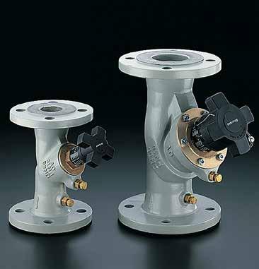
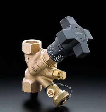
8 Job Name: Job Location: Submitted by: Spec Section: Engineer/Architect: Approval: Hydrocontrol R Bronze Manual Balancing Valve ½ - 2 H Specification Oventrop double regulating and commissioning valves Hydrocontrol R are installed in the pipework of central hot water heating and cooling systems and serve to achieve a hydronic balance between the various circuits of the system. Coil Kit Dimensions in Inches Dimension ½ ¾ 1 1¼ 1½ 2 L (F-NPT) L (sweat) H Installation Notes When installing the hydrocontrols, it is to be observed that the direction of flow conforms with the arrow on the valve body and that the valve is installed with a minimum of 3 D (3 x nominal pipe diameter) of straight pipe at the valve inlet and of 2 D (2 x nominal pipe diameter) of straight pipe at the valve outlet. L The balance is achieved by a presetting with memory position. The calculated flow rate or pressure loss for each individual pipe can be preset centrally and regulated precisely. The required values of presetting can be obtained from the flow charts. All intermediate values are infinitely adjustable. The selected presetting can be read off two scales. The Oventrop double regulating and commissioning valves have two threaded ports which are equipped with the pressure test points for measuring the differential pressure. Maximum working temperature: 300 F Maximum working pressure (F-NPT): 362 psi Maximum working pressure (sweat): 235 psi Using balancing valve for isolation: The hand wheel can be limited to any setting. This can be done by inserting a 3 mm allen key into the hole on the top of the handle and turning clockwise until it stops. Once this has been done, the valve can be closed down for isolation of the coil without losing the balanced setting. When the valve is reopened, the handle will be turned until it reaches the preset limit. Hydrocontrol R Manual Balancing Valve Recommended Size ends Flow range [GPM] Hydrocontrol valves can be installed in any orientation (e.g. vertical or horizontal). It is recomended to take caution if installing the valve with the test ports pointing down, as this could lead to clogging of the test ports. ½ ¾ ¼ ½ FNPT x FNPT Sweat x Sweat Size ½ ¾ 1 1¼ 1½ 2 PO Box 789 East Granby, CT Phone (860) Item Number (F-NPT) Item Number (sweat) HydroR_CoilKits-S

9 Hydrocontrol R Sweat or Thread ½ to 2 Valves Cv Values for Various Handwheel Settings Presetting or Handwheel Turns ½ ¾ 1 1¼ 1½ Hydrocontrol R Bronze Cv Values ½ to 2 Valves Accessories ½ - 2 Valves Flow measuring tolerance Hydrocontrol Valve Accessories Set of 2 pressure test points Item Extension piece for pressure test points 80mm Item Fill and drain ball valve 1 / 4 Item Insulation shell for Hydrocontrol R Size Item no. DN15 ½ DN20 ¾ DN DN32 1¼ DN40 1½ DN Measuring adapter for fill and drain ball valve Item Flow meter OV-DMC 2 Item PO Box 789 East Granby, CT Phone: (860) HydrocontrolRswt-S


10 Hydrocontrol F Cast Iron Double Regulating and Commissioning Valves Flanged ¾ - 16 (DN 20 - DN 400) Dimensions in Inches Size Item no. Weight L H max. d1 D K n x Ød DN20 ¾ lbs x 0.62 DN lbs x 0.62 DN32 1¼ lbs x 0.62 DN40 1½ lbs x 0.62 DN lbs x 0.75 DN65 2½ lbs x 0.75 DN lbs x 0.75 DN lbs x 0.75 DN lbs x 0.88 DN lbs x 0.88 DN lbs x 0.88 DN lbs x 1.0 DN lbs x 1.0 DN lbs x 1.12 DN lbs x 1.12 Installation Notes When installing the valves, it is to be observed that the direction of flow conforms with the arrow on the valve body and that the valve is installed with a minimum of 3 D (3 x nominal pipe diameter) of straight pipe at the valve inlet and of 2 D (2 x nominal pipe diameter) of straight pipe at the valve outlet. The double regulating and commissioning valves may be installed in either the supply or the return pipe. Product Specification Oventrop double regulating and commissioning valves Hydrocontrol F are installed in the pipework of central hot water heating and cooling systems and serve to achieve a hydronic balance between the various circuits of the system. The balance is achieved by a presetting with memory position. The calculated flow rate or pressure loss for each individual pipe can be preset centrally and regulated precisely. The required values of presetting can be obtained from the flow charts. All intermediate values are infinitely adjustable. The selected presetting can be read off two scales. The Oventrop double regulating and commissioning valves have two threaded ports which are equipped with the pressure test points for measuring the differential pressure. Specifications: Maximum working temperature: 300 F Maximum working pressure: 235 psi Temperature range: 15 F to 300 F Measuring Accuracy: +/- 5% Valve bodies manufactured from cast iron to ASME/ANSI B16.5 and flanged to 125 lb. standards. Valve body made of cast iron (ASTM A48(¾ -6 ), A536(8-16 )), hole circle of the flanged connection according to ANSI 150. PO Box 789 East Granby, CT Phone: (860) Bonnet, stem and disc made of bronze/dezincification resistant brass. Disc with PTFE seal. Double EPDM O-ring stem seal. 3-HydrocontrolF-S
11 Hydrocontrol F Cast Iron Valves Cv Values ¾ - 12 Accessories Hydrocontrol F Flanged ¾ to 12 valves Cv Values for Various Handwheel Settings Presetting or Handwheel Turns ¾ 1 1¼ 1½ 2 2½ Hydrocontrol Valve Accessories Set of 2 pressure test points Item Extension piece for pressure test points 80mm Item Fill and drain ball valve 1 / 4 Item Measuring adapter for fill and drain ball valve Item Flow meter OV-DMC 2 Item Insulation shell for Hydrocontrol F & G SIze Item no. DN20 ¾ DN DN32 1¼ DN40 1½ DN DN65 2½ DN DN DN DN PO Box 789 East Granby, CT Phone: (860) HydrocontrolF-S

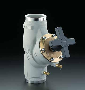
12 Hydrocontrol G Cast Iron Double Regulating and Commissioning Valves Grooved 2½ - 12 (DN 65 - DN 300) Dimensions in Inches Size Item no. Weight L H D d1 DN65 2½ lbs DN lbs DN lbs DN lbs DN lbs DN lbs DN lbs DN lbs Installation Notes When installing the valves, it is to be observed that the direction of flow conforms with the arrow on the valve body and that the valve is installed with a minimum of 3 D (3 x nominal pipe diameter) of straight pipe at the valve inlet and of 2 D (2 x nominal pipe diameter) of straight pipe at the valve outlet. The double regulating and commissioning valves may be installed in either the supply or the return pipe. Product Specification Oventrop double regulating and commissioning valves Hydrocontrol G are installed in the pipework of central hot water heating and cooling systems and serve to achieve a hydronic balance between the various circuits of the system. The balance is achieved by a presetting with memory position. The calculated flow rate or pressure loss for each individual pipe can be preset centrally and regulated precisely. The required values of presetting can be obtained from the flow charts. All intermediate values are infinitely adjustable. The selected presetting can be read off two scales. The Oventrop double regulating and commissioning valves have two threaded ports which are equipped with the pressure test points for measuring the differential pressure. Specifications: Maximum working temperature: 300 F Maximum working pressure: 362 psi Temperature range: 15 F to 300 F Measuring Accuracy: +/- 5% Groove connections for couplings. PO Box 789 East Granby, CT Phone: (860) Valve bodies manufactured from cast iron to ASME/ANSI B16.5 (ASTM A48(2½ -6 ), A536(8-12 )). Bonnet, stem and disc made of bronze/dezincification resistant brass. Disc with PTFE seal. Double EPDM O-ring stem seal. 3-HydrocontrolG-S

13 Hydrocontrol G Cast Iron Cv Values 2½ - 12 Valves Accessories Hydrocontrol G Grooved ¾ to 12 valves Cv Values for Various Handwheel Settings Presetting or Handwheel Turns 2½ Hydrocontrol Valve Accessories Set of 2 pressure test points Item Extension piece for pressure test points 80mm Item Fill and drain ball valve 1 / 4 Item Insulation shell for Hydrocontrol F & G SIze Item no. DN65 2½ DN DN DN DN Measuring adapter for fill and drain ball valve Item Flow meter OV-DMC 2 Item PO Box 789 East Granby, CT Phone: (860) HydrocontrolG-S
14 TYPICAL SPECIFICATIONS BALANCING VALVES ½ (DN15) 12 (DN300) 1.0 General Furnish and install Oventrop balancing valves, as shown on the drawings and/or schedules, to ensure the accurate balancing of all flows in the hydronic heating and cooling systems. Water balancing shall meet the specified flows with a maximum tolerance of +/- 5%. Upon completion, the balancing shall be documented in a report, which shall be submitted to the engineer for approval. 2.0 Balancing Valve Characteristics 2.1 All balancing valves shall be of the Y pattern globe style design. All balancing valves must offer a minimum of seven (7) full rotations of the handwheel for positioning accuracy of +/- 1%. 2.2 All balancing valves shall have documented measuring accuracy of +/- 5% within the normal setting range of the valve. 2.3 All balancing valves shall have integral self-sealing ports for measuring differential pressure and fluid temperature using standard pressure and temperature test probes. Test ports shall be located in line with the handwheel, on the same end of the valve and shall be removable to function as integral drain ports. 2.4 All balancing valves must offer 100% positive, leakproof shutoff against the same fluid temperature and pressure ratings as the body. Minimum body ratings are 232 psi (PN16) at 300 degrees F (150 C). 2.5 All balancing valves must include a hidden memory stop to ensure return to the balanced position after shutoff. An enclosed anti-tamper lock feature shall prevent handwheel repositioning after setting. 2.6 All balancing valves ½ (DN15) through 12 (DN300) shall have digital/vernier adjustment for precise readout. 2.7 All balancing valves shall be manufactured by the company complying with international quality standard ISO (Option) All balancing valves in sizes ½ (DN15) through 8 (DN200) shall be capable of being enclosed within factory contoured insulations with ASTM flame spread of 25 or less and a rating of E-84. Insulation R value shall be (Option) A valved hose bib fitting shall be available for installation on all ½ (DN15) through 12 (DN300) sizes. The hose bib fitting shall be capable of being placed on either side of the valve plug to accommodate draining and filling of horizontal or vertical coils. 3.0 Material Characteristics All balancing valves in sizes ½ (DN15) through 2 (DN50) shall have bronze bodies and either solder or NPT threaded connections to match the piping system. Valve bodies in sizes 2½ (DN65) through 12 (DN300) shall be manufactured from cast iron equivalent to ASME/ANSI B16.5 and shall be flanged to 125 lb. standards. All wetted brass parts shall be alloyed to resist dezincification. No dielectric fittings shall be required for installation. 4.0 Valve Sizing All balancing valves shall be sized to perform in a normal operation range between 25% and 100% of the full open position, at a minimum differential pressure between 1 to 3 ft. WG. 5.0 Manufacturer. 6.0 Warranty Valves shall be free from material and workmanship defects for a period of 5 years from date of installation or from 5½ years from date of shipment, whichever comes first. Oventrop reserves the right to make revisions to its products, their specifications, this bulletin, and related information without notice. PO Box Kripes Road East Granby, Connecticut Phone Fax
15 This page is intentionally left blank. 15
16 Hydrocontrol MTR Bronze Double Regulating and Commissioning Valves Thread 1/2 -LF - 2 (DN 15LF - DN 50) Job Name: Job Location: Submitted by: Spec Section: Engineer/Architect: Approval: Dimensions in Inches Size Item no. Cv D L H DN15LF ½" FNPT ½ DN15MF ½" FNPT ½ DN15 ½" FNPT ½ DN20 ¾" FNPT ¾ DN25 1" FNPT DN32 1¼" FNPT ¼ DN40 1½" FNPT ½ DN50 2" FNPT Size Item no. Minimum Flow [GPM] Maximum Flow [GPM] DN15LF ½" FNPT DN15MF ½" FNPT DN15 ½" FNPT DN20 ¾" FNPT DN25 1" FNPT DN32 1¼" FNPT DN40 1½" FNPT DN50 2" FNPT Product Specification Oventrop double regulating and commissioning valves Hydrocontrol MTR are installed in the pipework of central hot water heating and cooling systems and serve to achieve a hydronic balance between the various circuits of the system. The balance is achieved by a presetting with memory position. The calculated flow rate or pressure loss for each individual pipe can be preset centrally and regulated precisely. The required values of presetting can be obtained from the flow charts. All intermediate values are infinitely adjustable. The selected presetting can be read off two scales. The Oventrop double regulating and commissioning valves have two threaded ports which are equipped with the pressure test points for measuring the differential pressure across an integrated venturi. Specifications: Maximum working temperature: 300 F Maximum working pressure: 360 psi Bonnet, stem and disc made of bronze/dezincification resistant brass. Disc with PTFE seal. Double EPDM O-ring stem seal. PO Box 789 East Granby, CT Phone: (860) GPM = PSID Cv 3-HydrocontroMTR-S
17 Hydrocontrol MTR Bronze 1/2" to 2" Valves Accessories Pressure drop [PSI] measured at the valve for select flow rates [GPM] DN15LF ½ Flow rate - GPM PO Box 789 East Granby, CT Phone: (860) DN15MF ½ DN15 ½ DN20 ¾ DN25 1 DN32 1¼ DN40 1½ DN Hydrocontrol Valve Accessories Set of two pressure test points Item Extension piece for pressure test points 80mm Item Fill and drain ball valve 1/4" Item Measuring adapter for fill-and-drain ball valve Item Flow meter OV-DMC 2 Item Insulation Shell for Hydrocontrol MTR SIze Item no. DN15 1/2" DN20 3/4" DN25 1" DN32 1¼" DN40 1½" DN50 2" HydrocontrolMTR-S
18 Hydrocontrol MTR Bronze Double Regulating and Commissioning Valves Thread 1/2 -LF - 2 (DN 15LF - DN 50) Job Name: Job Location: Submitted by: Spec Section: Engineer/Architect: Approval: Dimensions in Inches Size Item no. Cv D L H DN15LF ½" SWT ½ DN15MF ½" SWT ½ DN15 ½" SWT ½ DN20 ¾" SWT ¾ DN25 1" SWT DN32 1¼" SWT ¼ DN40 1½" SWT ½ DN50 2" SWT Size Item no. Minimum Flow [GPM] Maximum Flow [GPM] DN15LF ½" SWT DN15MF ½" SWT DN15 ½" SWT DN20 ¾" SWT DN25 1" SWT DN32 1¼" SWT DN40 1½" SWT DN50 2" SWT Product Specification Oventrop double regulating and commissioning valves Hydrocontrol MTR are installed in the pipework of central hot water heating and cooling systems and serve to achieve a hydronic balance between the various circuits of the system. The balance is achieved by a presetting with memory position. The calculated flow rate or pressure loss for each individual pipe can be preset centrally and regulated precisely. The required values of presetting can be obtained from the flow charts. All intermediate values are infinitely adjustable. The selected presetting can be read off two scales. The Oventrop double regulating and commissioning valves have two threaded ports which are equipped with the pressure test points for measuring the differential pressure across an integrated venturi. Specifications: Maximum working temperature: 300 F Maximum working pressure: 235 psi Bonnet, stem and disc made of bronze/dezincification resistant brass. Disc with PTFE seal. Double EPDM O-ring stem seal. PO Box 789 East Granby, CT Phone: (860) GPM = PSID Cv 3-HydrocontroMTR-S
19 Hydrocontrol MTR Bronze 1/2" to 2" Valves Accessories Pressure drop [PSI] measured at the valve for select flow rates [GPM] DN15LF ½ Flow rate - GPM PO Box 789 East Granby, CT Phone: (860) DN15MF ½ DN15 ½ DN20 ¾ DN25 1 DN32 1¼ DN40 1½ DN50 2 Hydrocontrol Valve Accessories Set of two pressure test points Item Extension piece for pressure test points 80mm Item Fill and drain ball valve 1/4" Item Measuring adapter for fill-and-drain ball valve Item Flow meter OV-DMC 2 Item Insulation Shell for Hydrocontrol MTR SIze Item no. DN15 1/2" DN20 3/4" DN25 1" DN32 1¼" DN40 1½" DN50 2" HydrocontrolMTR-S
20 Job Name: Job Location: Submitted by: Spec Section: Engineer/Architect: Approval: Low lead CS Manual Balancing Valve ½ - 2 H1 H W L ½ - 1 H1 H Specification The Low lead CS balancing valve is a ball valve style valve made of a low lead brass body and a nickel plated brass ball. It is available in sizes from 1/2 to 2 with either FNPT or solder connections. The valve comes standard with two pressure test ports. 1¼ - 2 W L Maximum working temperature: 250 F Maximum working pressure: 400 psi Item: Coil Kit Dimensions in Inches Dimension ½ ¾ 1 1¼ 1½ 2 L - FNPT L - SWT H H W Cv /2 FNPT /4 FNPT FNPT /4 FNPT /2 FNPT FNPT /2 SWT /4 SWT SWT /4 SWT /2 SWT SWT Installation Notes When installing the balancing valve, it is to be observed that the direction of flow conforms with the arrow on the valve body and that the valve is installed with a minimum of 3 D (3 x nominal pipe diameter) of straight pipe at the valve inlet and of 1 D (1 x nominal pipe diameter) of straight pipe at the valve outlet. 1 20
21 Low lead CS Manual Balancing Valve ½ - 2 Recommended flow range Size Low lead CS Manual Balancing Valve Recommended Flow range [GPM] ½ ¾ ¼ ½ ends FNPT x FNPT Sweat x Sweat Cv table for various settings Percent open ½ ¾ 1 1¼ 1½

22 Series 810 Dynamic balancing valve Sizes ½ - 2 Size Body Item Number ½ FNPT A _ ½ SWT A _ ¾ FNPT A _ ¾ SWT A _ 1 A FNPT A _ 1 A SWT A _ 1 B FNPT B _ 1 B SWT B _ 1¼ FNPT C _ 1¼ SWT C _ 1½ C FNPT C _ 1½ C SWT C _ 1½ D FNPT D _ 1½ D SWT D _ 2 FNPT E _ 2 SWT E _ Body Example valve selection: 9.0 GPM flow rate for 1¼ SWT valve with 1 SWT tailpiece FLOW RATE Tailpiece Standard Available Flow Rates First Letter A B C D E Second Letter Flow Rate [GPM] A B C D E F G H I J K L M N O P Q 22 R 24 S 26 T 28 U 30 Item number CE Dynamic balancing valve tailpiece designations ½ Body Tailpieces ¾ Body Tailpieces 1 Body Tailpieces 1¼ Body Tailpieces 1½ Body Tailpieces 2 Body Tailpieces Item Item Item Item Item Item 11 ½ FNPT 11 ½ FNPT 13* ½ MNPT * 31 1 FNPT 41 1¼ FNPT 51 1½ FNPT 12 ½ SWT 12 ½ SWT 22* ¾ SWT * 32 1 SWT 42 1¼ SWT 52 1½ SWT 13 ½ MNPT 13 ½ MNPT 23* ¾ MNPT * 33 1 MNPT 43 1¼ MNPT 53 1½ MNPT 21 ¾ FNPT 31 1 FNPT 41 1¼ FNPT 51 1½ FNPT 61 2 FNPT 22 ¾ SWT 32 1 SWT 42 1¼ SWT 52 1½ SWT 62 2 SWT 23 ¾ MNPT 33 1 MNPT 43 1¼ MNPT 53 1½ MNPT 63 2 MNPT * For 1 A body ONLY. 22
23 Job Name: Job Location: Submitted by: Spec Section: Engineer/Architect: Approval: Dynamic balancing valve ½ - 2 H PT ports P Tailpiece Body C A All dimensions are in inches Body Size ½ ¾ 1 A 1 B 1¼ 1½ C 1½ D 2 A - FNPT A - SWT C H P Product Specification: Oventrop dynamic balancing valves are design to maintain a set maximum flow rate over a large differential pressure range. The flow control mechanism is a spring loaded cartridge insert. This prevents over flow conditions at the valve. Control Range: 2-32 PSID Accuracy: +/- 5% Maximum Working Pressure: 600 PSI Maximum Temperature: 250 F Start-Up Head Loss: 5 fthd T ½ Body Tailpieces ¾ Body Tailpieces 1 Body Tailpieces 1¼ Body Tailpieces 1½ Body Tailpieces 2 Body Tailpieces T T T T T T 0.83 ½ FNPT 0.83 ½ FNPT 1.5 ½ MNPT FNPT 1.0 1¼ FNPT ½ FNPT 0.83 ½ SWT 0.87 ½ SWT 0.98 ¾ SWT SWT ¼ SWT ½ SWT 1.5 ½ MNPT 1.5 ½ MNPT 1.56 ¾ MNPT MNPT 1.8 1¼ MNPT ½ MNPT 0.83 ¾ FNPT FNPT 1.0 1¼ FNPT ½ FNPT FNPT 0.98 ¾ SWT SWT ¼ SWT ½ SWT SWT 1.56 ¾ MNPT MNPT 1.8 1¼ MNPT 1.8 1½ MNPT MNPT 0.98 High Flow 1 FNPT High Flow 1 SWT High Flow 1 MNPT 23 East Granby, CT

24 Job Name: Job Location: Submitted by: Spec Section: Engineer/Architect: Approval: Dynamic balancing valve 2 ½ - 6 H P C A Specification The Series 810 is a wafer type Automatic Pressure Independent Flow Limiting Device with a full flange face. The Series 810 is designed to fit between two ANSI Class 125 flanges. The Series 810 is supplied with one or more stainless steel flow limiting cartridges that can be removed for cleaning, inspection, and, if necessary, cartridge exchange. The Series 810 has two pressure/ temperature ports. The Series 810 has a butterfly valve for positive shutoff. Maximum working temperature: 250 F Maximum working pressure: 600 WOG / CWP Valve Dimensions in Inches Valve Sizes and Dimensions Dimensions Valve Body Size 2 ½ A C H 9.0 P # of Flow Cartridges Maximum flow rate [GPM] at 2-32 PSID Maximum flow rate [GPM] at 5-60 PSID Weight [lbs] Item number East Granby, CT

25 Hydrocontrol Coil Hookup Kits Hydrocontrol RY - Hydrocontrol R manual balancing valve - Union fitting with air vent and PT port - Y-Ball strainer with PT, bypass, and drain ports Hydrocontrol RI - Hydrocontrol R manual balancing valve - Union fitting with air vent and PT port - Isolator ball valve with PT and drain ports Balancing Valve PT ports ATC by others Union Fitting PT port Air vent Balancing Valve PT ports Out In ATC by others Union Fitting Tailpiece Air vent Body Tailpiece Bypass Coil Tailpiece Optional Tailpieces PT port PT port Tailpiece Body Coil Body Y-Ball Strainer Blow down drain Body Isolator Ball Valve Blow down drain Hydrocontrol AY - Dynamic balancing valve - Union fitting with air vent and PT port - Y-Ball strainer with PT, bypass, and drain ports Hydrocontrol AI - Dynamic balancing valve - Union fitting with air vent and PT port - Isolator ball valve with PT and drain ports Dynamic Balancing Valve ATC by others Union Fitting Tailpiece Air vent Dynamic Balancing Valve ATC by others Union Fitting Tailpiece Air vent PT port Body PT port Body PT port Bypass Tailpiece Coil PT port Tailpiece Coil Body Y-Ball Strainer Blow down drain Body Isolator Ball Valve Blow down drain 25


26 Job Name: Job Location: Submitted by: Spec Section: Engineer/Architect: Approval: Series 801 Y-Ball Strainer with PT Port and Drain ½ - 2 Coil Kits H1 H2 T Dimensions L W ½ Tailpiece ¾ Tailpiece 1 Tailpiece 1¼ Tailpiece 1½ Tailpiece 2 Tailpiece T Coil Kit Dimensions in Inches L Strainer Kit Sizes and Dimensions Strainer Body Size ½ ¾ 1 1¼ 1½ 2 FNPT SWT FNPT MNPT SWT FNPT MNPT SWT FNPT MNPT SWT FNPT MNPT SWT FNPT MNPT SWT FNPT MNPT SWT H H H W Bypass port ½ ½ ½ ¾ ¾ 1¼ H 26 Specification Oventrop strainer coil kit is an assembly for the supply side of a fan coil unit or air handler. Each assembly consists of a y-strainer, a ball valve, a PT port, and a drain. A union connection at the strainer is male, female, or sweat. A sweat or female connection is available on the ball valve end. Oblique pattern strainer for vertical and horizontal installation. Bronze body, with wire basket made of stainless steel. Replaceable wire baskets. Wire basket: 20 mesh Ball valve made of brass, ball made of chrome plated brass, PTFE seats, EPDM O-ring seal. Fill and drain valve, with ball valve. Ball made of chrome plated brass, PTFE seats, O-ring seal. Maximum working temperature: 250 F Maximum working pressure: 600 PSI / CWP
27 Series 801 Y-Ball Strainer with PT Port and Drain Sizes ½ - 2 Size Item Number ½ _ ¾ _ _ 1¼ _ 1½ _ _ PT port Bypass Tailpiece Example valve selection: 1¼ SWT valve with ¾ MNPT tailpiece Item number Body Blow down drain Y-Ball Strainers body and tailpiece designations for FNPT body valves ½ Body Tailpieces ¾ Body Tailpieces 1 Body Tailpieces 1¼ Body Tailpieces 1½ Body Tailpieces 2 Body Tailpieces Item Item Item Item Item Item 1111 ½ FNPT 2111 ½ FNPT 3113 ½ MNPT 4113 ½ MNPT 5123 ¾ MNPT MNPT 1112 ½ SWT 2112 ½ SWT 3122 ¾ SWT 4123 ¾ MNPT MNPT ¼ MNPT 1113 ½ MNPT 2113 ½ MNPT 3123 ¾ MNPT MNPT ¼ MNPT ½ MNPT 2121 ¾ FNPT FNPT ¼ FNPT ½ FNPT FNPT 2122 ¾ SWT SWT ¼ SWT ½ SWT SWT 2123 ¾ MNPT MNPT ¼ MNPT ½ MNPT MNPT Y-Ball Strainers body and tailpiece designations for SWT body valves ½ Body Tailpieces ¾ Body Tailpieces 1 Body Tailpieces 1¼ Body Tailpieces 1½ Body Tailpieces 2 Body Tailpieces Item Item Item Item Item Item 1211 ½ FNPT 2211 ½ FNPT 3213 ½ MNPT 4213 ½ MNPT 5223 ¾ MNPT MNPT 1212 ½ SWT 2212 ½ SWT 3222 ¾ SWT 4223 ¾ MNPT MNPT ¼ MNPT 1213 ½ MNPT 2213 ½ MNPT 3223 ¾ MNPT MNPT ¼ MNPT ½ MNPT 2221 ¾ FNPT FNPT ¼ FNPT ½ FNPT FNPT 2222 ¾ SWT SWT ¼ SWT ½ SWT SWT 2223 ¾ MNPT MNPT ¼ MNPT ½ MNPT MNPT 27
28 Job Name: Submitted by: Spec Section: Series 802 Accessory Union with PT Port and Air vent Sizes ½ - 2 Job Location: Engineer/Architect: Approval: H1 Specification Oventrop union for the return side of a fan coil unit or air handler. The fixed connection of the union is female or sweat. The union connection is available on the control valve side. Union made of forged brass, O-ring seal for union The union has an airvent and a pressure test point Maximum working temperature: 250 F Maximum working pressure: 600 psi / CWP H2 L T Coil Kit Dimensions in Inches Union Kit Sizes and Dimensions Union Body Size Dimensions ½ ¾ 1 1¼ 1½ 2 H H T L ½ Union ¾ Union 1 Union 1¼ Union 1½ Union 2 Union FNPT SWT FNPT MNPT SWT FNPT MNPT SWT FNPT MNPT SWT FNPT MNPT SWT FNPT MNPT SWT FNPT MNPT SWT

29 Series 802 Accessory Union with PT Port and Air vent Sizes ½ - 2 Size Item Number ½ _ ¾ _ _ 1¼ _ 1½ _ _ Example valve selection: 1¼ SWT valve with ¾ MNPT tailpiece Item number Air vent PT port Body Tailpiece Isolator body and tailpiece designations for FNPT body valves ½ Body Tailpieces ¾ Body Tailpieces 1 Body Tailpieces 1¼ Body Tailpieces 1½ Body Tailpieces 2 Body Tailpieces Item Item Item Item Item Item 1111 ½ FNPT 2111 ½ FNPT 3113 ½ MNPT 4113 ½ MNPT 5123 ¾ MNPT MNPT 1112 ½ SWT 2112 ½ SWT 3122 ¾ SWT 4123 ¾ MNPT MNPT ¼ MNPT 1113 ½ MNPT 2113 ½ MNPT 3123 ¾ MNPT MNPT ¼ MNPT ½ MNPT 2121 ¾ FNPT FNPT ¼ FNPT ½ FNPT FNPT 2122 ¾ SWT SWT ¼ SWT ½ SWT SWT 2123 ¾ MNPT MNPT ¼ MNPT ½ MNPT MNPT Isolator body and tailpiece designations for SWT body valves ½ Body Tailpieces ¾ Body Tailpieces 1 Body Tailpieces 1¼ Body Tailpieces 1½ Body Tailpieces 2 Body Tailpieces Item Item Item Item Item Item 1211 ½ FNPT 2211 ½ FNPT 3213 ½ MNPT 4213 ½ MNPT 5223 ¾ MNPT MNPT 1212 ½ SWT 2212 ½ SWT 3222 ¾ SWT 4223 ¾ MNPT MNPT ¼ MNPT 1213 ½ MNPT 2213 ½ MNPT 3223 ¾ MNPT MNPT ¼ MNPT ½ MNPT 2221 ¾ FNPT FNPT ¼ FNPT ½ FNPT FNPT 2222 ¾ SWT SWT ¼ SWT ½ SWT SWT 2223 ¾ MNPT MNPT ¼ MNPT ½ MNPT MNPT 29
30 Job Name: Job Location: Submitted by: Spec Section: Engineer/Architect: Approval: Supply Side Coil Kit Isolator with PT Port and Drain ½ - 2 Coil Kits H1 H2 H Specification Oventrop strainer coil kit is an assembly for the supply side of a fan coil unit or air handler. Each assembly consists of a ball valve, a PT port, and a drain. A union connection at the isolator is male, female, or sweat. A sweat or female connection is available on the ball valve end. Ball valve made of brass, ball made of chrome plated brass, PTFE seats, EPDM O-ring seal. Fill and drain valve, with ball valve. Ball made of chrome plated brass, PTFE seats, O-ring seal. Maximum working temperature: 250 F Maximum working pressure: 600 PSI / CWP T L Coil Kit Dimensions in Inches Dimensions Isolator Kit Sizes and Dimensions Isolator Body Size ½ ¾ 1 1¼ 1½ 2 T L ½ Tailpiece ¾ Tailpiece 1 Tailpiece 1¼ Tailpiece 1½ Tailpiece 2 Tailpiece FNPT SWT FNPT MNPT SWT FNPT MNPT SWT FNPT MNPT SWT FNPT MNPT SWT FNPT MNPT SWT FNPT MNPT SWT H H H PO Box 789 East Granby, CT Phone (860) Isolator_CoilKits-S
31 Series 803 Isolator with PT Port and Drain Sizes ½ - 2 Size Item Number ½ _ ¾ _ _ 1¼ _ 1½ _ _ PT port Tailpiece Example valve selection: 1¼ SWT valve with ¾ MNPT tailpiece Item number Body Blow down drain Isolator body and tailpiece designations for FNPT body valves ½ Body Tailpieces ¾ Body Tailpieces 1 Body Tailpieces 1¼ Body Tailpieces 1½ Body Tailpieces 2 Body Tailpieces Item Item Item Item Item Item 1111 ½ FNPT 2111 ½ FNPT 3113 ½ MNPT 4113 ½ MNPT 5123 ¾ MNPT MNPT 1112 ½ SWT 2112 ½ SWT 3122 ¾ SWT 4123 ¾ MNPT MNPT ¼ MNPT 1113 ½ MNPT 2113 ½ MNPT 3123 ¾ MNPT MNPT ¼ MNPT ½ MNPT 2121 ¾ FNPT FNPT ¼ FNPT ½ FNPT FNPT 2122 ¾ SWT SWT ¼ SWT ½ SWT SWT 2123 ¾ MNPT MNPT ¼ MNPT ½ MNPT MNPT Isolator body and tailpiece designations for SWT body valves ½ Body Tailpieces ¾ Body Tailpieces 1 Body Tailpieces 1¼ Body Tailpieces 1½ Body Tailpieces 2 Body Tailpieces Item Item Item Item Item Item 1211 ½ FNPT 2211 ½ FNPT 3213 ½ MNPT 4213 ½ MNPT 5223 ¾ MNPT MNPT 1212 ½ SWT 2212 ½ SWT 3222 ¾ SWT 4223 ¾ MNPT MNPT ¼ MNPT 1213 ½ MNPT 2213 ½ MNPT 3223 ¾ MNPT MNPT ¼ MNPT ½ MNPT 2221 ¾ FNPT FNPT ¼ FNPT ½ FNPT FNPT 2222 ¾ SWT SWT ¼ SWT ½ SWT SWT 2223 ¾ MNPT MNPT ¼ MNPT ½ MNPT MNPT 31
32 Series 804 Union Adapter Sizes ½ - 2 Job Name: Job Location: Submitted by: Spec Section: Engineer/Architect: Approval: Specification Series 804 union adapter for connection from balancing valve to control valve. Maximum working temperature: 250 F Maximum working pressure: 600 psi / CWP H1 L T Coil Kit Dimensions in Inches Union Sizes and Dimensions Union Body Size Dimensions ½ ¾ 1 1¼ 1½ 2 H L MNPT T ½ Union ¾ Union 1 Union 1¼ Union 1½ Union 2 Union FNPT MNPT SWT FNPT MNPT SWT FNPT MNPT SWT FNPT MNPT SWT FNPT MNPT SWT FNPT MNPT SWT

33 Series 804 Union Adapter Sizes ½ - 2 Size Item Number ½ _ ¾ _ _ 1¼ _ 1½ _ _ Example valve selection: Body 1¼ SWT valve with ¾ MNPT tailpiece Item number Tailpiece Union Adapter body and tailpiece designations for MNPT body valves ½ Body Tailpieces ¾ Body Tailpieces 1 Body Tailpieces 1¼ Body Tailpieces 1½ Body Tailpieces 2 Body Tailpieces Item Item Item Item Item Item 1111 ½ FNPT 2111 ½ FNPT 3113 ½ MNPT 4113 ½ MNPT 5123 ¾ MNPT MNPT 1112 ½ SWT 2112 ½ SWT 3122 ¾ SWT 4123 ¾ MNPT MNPT ¼ MNPT 1113 ½ MNPT 2113 ½ MNPT 3123 ¾ MNPT MNPT ¼ MNPT ½ MNPT 2121 ¾ FNPT FNPT ¼ FNPT ½ FNPT FNPT 2122 ¾ SWT SWT ¼ SWT ½ SWT SWT 2123 ¾ MNPT MNPT ¼ MNPT ½ MNPT MNPT 33

34 Job Name: Job Location: Submitted by: Spec Section: Engineer/Architect: Approval: Flex hoses for ½ - 2 Coil Kits Size Item Number ½ C ¾ C C 1¼ C 1½ C C Specification Oventrop flex hoses are made of EPDM with a 304 single stainless steel braid. Working temperature range: 5 to 230 ºF Standard connection: Brass Fixed MNPT x Brass Swivel MNPT Example hose selection: ¾ Hose with 24 overall length Item number C Size Lengths [in.] Hose Type Minimum Bend Radius Maximum Working Pressure ½ 12, 18, 24, PSI ¾ 12, 18, 24, PSI 1 12, 18, 24, stainless PSI steel braided 1¼ 18, 24, 36 EPDM PSI 1½ 18, 24, PSI 2 24, PSI Fixed MNPT end MNPT end 34
35 Flex hoses for ½ - 2 Coil Kits All dimensions in inches F Length R min A min B D α max ½ ¾ ¼ ½
![Item Number Operating Voltage Pressure Independent Control Valves Control Signal Fail Position Stroke time [seconds] Characteristic Notes Item Flow rate](/docs-images/79/79244214/images/36-1.jpg "[GPM] Stroke Size Number Minimum Maximum [mm] Type 167 60 04 ½ 0.13 0.92 2.8 MNPTxFNPT 167 62 04 ½ 0.66 4.6 2.8 MNPTxFNPT 167 60 06 ¾ 0.66 4.6 2.8 MNPTxFNPT 167 61 06 ¾ 0.")

36 Item Number Operating Voltage Pressure Independent Control Valves Control Signal Fail Position Stroke time [seconds] Characteristic Notes Item Flow rate [GPM] Stroke Size Number Minimum Maximum [mm] Type ½ MNPTxFNPT ½ MNPTxFNPT ¾ MNPTxFNPT ¾ MNPTxFNPT MNPTxFNPT ¼ MNPTxFNPT ½ FNPTxFNPT FNPTxFNPT ½ Flanged Flanged Flanged Flanged Flanged 36
37 V 24V 24V 24V 24V 0-10V DC 0-10V DC Normally Closed 2 point, 3 point, 0-10V 2 point, 3 point, 0-10V 2 point, 3 point, 0-10V In place In place In place In place 60 s/mm 15 s/mm 15 s/mm 2 s/mm 2 s/mm Linear - Linear or equal percentage with Feedback Linear or equal percentage - Linear, equal percentage, or x2 with Feedback Linear, equal percentage, or x2 with Feedback Valve Size x x x ½ x x x ½ x x x ¾ x x ¾ x x 1 x x 1¼ x 1½ x 2 37 x 2½ x 3 x 4 x 5 x 6

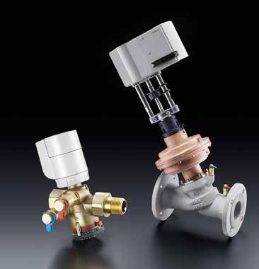
38 Cocon QTZ Pressure independent control valve Size: L1 L2 H1 H2 ½, ½ LF ¾ LF ¾ ¼ See back for dimensions with actuators Product specification Function: The Oventrop pressure independent control valve Cocon Q maintains a valve authority of 100% and the desired flow over a wide range of differential pressures. The Cocon Q is ideal for variable flow applications and makes selection and commissioning easy. Select the valve with the flow range that satisfies the desired flow rate, and set the design flow rate on site with a quick turn of the hand wheel. The valve is used for the hydronic balancing and temperature control of appliances or sections of the system in chilled ceiling, fan-coil, convector, central heating, and surface heating systems. Performance data: Maximum working temperature: 250 F (120 C) Minimum working temperature: 14 F (-10 C) Maximum working pressure: 232 psi (16 Bar) Maximum differential pressure: 60 psi (4 Bar) Minimum differential pressure: See table Flow accuracy: +/- 10% Positioning accuracy: 0.1 GPM Close-off pressure with /06: 232 psi PO Box 789 East Granby, CT Phone: (860) Item numbers: With test points Item number Size Flow range Male/female ports Male ports ½ LF GPM ½ GPM ¾ LF GPM ¾ GPM GPM ¼ GPM Accessories: Lead sealing locking wire:
 Medium floating time Maximum fluid temperature [F] Allowable installation position Actuator addition to H1 [in] 101 27 06")


39 % Piston Stroke % Piston Stroke % Piston Stroke Cocon QTZ Pressure independent control valve 24V actuators with M30x1.5 connection Item number Model Operating behavior (control signal) Medium floating time Maximum fluid temperature [F] Allowable installation position Actuator addition to H1 [in] Electromotive 0-10 V with feedback Electromotive On/Off (2-point), Floating (3-point), 0-10 V (proportional) ~ 15 s/ mm 203 Any, but not upside down 1.9 Proportional actuator characteristic lines / / Valve characteristic line Effective valve lift % 0 Drive 0 Drive 0 Drive Construction: The Cocon Q has a brass body and is alloyed to resist dezincification (DZR). No dielectric fittings are required for installation. The valve stem is stainless steel and the flexible components are made of EPDM and PTFE. The Cocon Q offers a hand wheel mounted opposite and inline with the actuator. The actuator and hand wheel are oriented 15 degrees from vertical to allow for easier operation. The valve has integral selfsealing ports for measuring differential pressure and fluid temperature using standard pressure and temperature test probes. Test ports are located perpendicular to the hand wheel, on the same side of the valve, and are replaceable with blind plugs if not needed. Test ports are spaced 1.0 inch apart and extend 1.5 inches from the valve body. The hand wheel is adjustable while the valve is in operation with the actuator installed. The Cocon Q includes a locking clip stop to ensure the balanced position while in operation and to prevent hand wheel repositioning after setting. Flow rate PO Box 789 East Granby, CT Phone: (860)
40 TYPICAL SPECIFICATIONS Pressure independent control valves ½ (DN15) 1¼ (DN32) 1.0 General Furnish and install Oventrop balancing valves, as shown on the drawings and/or schedules, to ensure the accurate balancing of all flows in the hydronic heating and cooling systems. Water balancing and control shall meet the specified flows. 2.0 Construction 2.1 All control valves shall be of the pressureindependent design. All control valves shall have a constant control valve authority of 100% over the full allowable pressure and flow range. All control valves must offer a hand wheel mounted opposite and inline with the actuator. The actuator and hand wheel shall be oriented 15 degrees from vertical to allow for easier operation. 2.2 All control valves shall have documented measuring accuracy of +/- 10% within the normal setting range of the valve. 2.3 All control valves shall have integral self-sealing ports for measuring differential pressure and fluid temperature using standard pressure and temperature test probes. Test ports shall be located perpendicular to the hand wheel, on the same side of the valve, and shall be replaceable with blind plugs if not needed. Test ports shall be spaced no more than 1.0 inch apart and extend no more than 1.5 inches from the valve body. 2.4 All control valves shall have maximum body ratings no less than 232 psi (PN16) at 250 degrees F (120 C). 2.5 All control valves must include a locking clip stop to ensure the balanced position while in operation and to prevent hand wheel repositioning after setting. 2.6 All control valves ½ (DN15) through 1¼ (DN32) shall have hand wheel adjustment for precise readout on the opposite side of the valve from the actuator. The hand wheel shall be adjustable while the valve is in operation with the actuator installed. The hand wheel shall be marked in gallons per minute and shall have a minimum positioning accuracy of 0.1 GPM. 2.7 All control valves shall be manufactured by the company complying with international quality standard ISO All control valves shall have a threaded connection of M30x1.5 for the actuator. All control valves shall have a stem travel of no less than 0.11 inches (2.8mm) over the full range of valve flow. All actuators shall be supplied by Oventrop. All actuators shall be capable of operating over the full flow and pressure range of the valve. 3.0 Material Characteristics All control valves in sizes ½ (DN15) through 1¼ (DN32) shall have brass bodies and NPT threaded connections to match the piping system. All wetted brass parts shall be alloyed to resist dezincification (DZR). No dielectric fittings shall be required for installation. The valve stem shall be stainless steel. The flexible components shall be made of EPDM and PTFE. 4.0 Valve Sizing All control valves shall be sized to perform in a normal operation range at a minimum differential pressure of 2.2 to 6 psi (0.15 to 0.4 Bar). All control valves shall have a maximum working differential pressure of no less than 60 psi (4 Bar). All control valves shall be selected based on their allowable flow range. 5.0 Manufacturer. 6.0 Warranty Valves shall be free from material and workmanship defects for a period of 5 years from date of installation or from 5½ years from date of shipment, whichever comes first. Oventrop reserves the right to make revisions to its products, their specifications, this bulletin, and related information without notice. PO Box Kripes Road East Granby, Connecticut Phone Fax

41 Cocon QTR Pressure independent control valve H2 Product specification Function: The Oventrop pressure independent control valve Cocon Q maintains a valve authority of 100% and the desired flow over a wide range of differential pressures. The Cocon Q is ideal for variable flow applications and makes selection and commissioning easy. Select the valve with the flow range that satisfies the desired flow rate, and set the design flow rate on site with a quick turn of the hand wheel. The valve is used for the hydronic balancing and temperature control of appliances or sections of the system in chilled ceiling, fan-coil, convector, central heating, and surface heating systems. Min. differential pressure [psi] Size D L t H H2 1½ 1½ 4.72 ¾ Minimum operating differential pressure ½ 6.6 GPM 15.4 GPM 24 GPM 33 GPM 2 11 GPM 22 GPM 33 GPM 44 GPM Nominal value settings [GPM] PO Box 789 East Granby, CT Phone: (860) Performance data: Maximum working temperature: 250 F (120 C) Minimum working temperature: -4 F (-20 C) Maximum working pressure: 232 psi (16 Bar) Maximum differential pressure: 60 psi (4 Bar) Minimum differential pressure: 2.9 to 4.35 psi (0.2 to 0.3 Bar) Flow accuracy: +/- 10% Positioning accuracy: 1 GPM Close-off pressure with : 232 psi Item numbers: With test points Size Flow range Item number 1½ GPM GPM Accessories: Lead sealing locking wire:

42 Cocon QTR Pressure independent control valve Valve characteristic line Construction: The Cocon Q has a bronze body and the brass components are alloyed to resist dezincification (DZR). No dielectric fittings are required for installation. The valve stem is stainless steel and the flexible components are made of EPDM and PTFE. The Cocon Q offers a hand wheel mounted inline with the actuator. The valve has integral self-sealing ports for measuring differential pressure and fluid temperature using standard pressure and temperature test probes. Test ports are located on the same end and on the same side of the valve. Test ports are spaced 1.0 inch apart and extend 1.5 inches from the valve body. The Cocon Q includes a locking clip stop to ensure the balanced position while in operation and to prevent hand wheel repositioning after setting. Effective valve lift % Flow rate PO Box 789 East Granby, CT Phone: (860)
43 TYPICAL SPECIFICATIONS Pressure independent control valves 1½ (DN40) 2 (DN50) 1.0 General Furnish and install Oventrop balancing valves, as shown on the drawings and/or schedules, to ensure the accurate balancing of all flows in the hydronic heating and cooling systems. Water balancing and control shall meet the specified flows. 2.0 Construction 2.1 All control valves shall be of the pressureindependent design. All control valves shall have a constant control valve authority of 100% over the full allowable pressure and flow range. 2.2 All control valves shall have documented measuring accuracy of +/- 10% within the normal setting range of the valve. 2.3 All control valves shall have integral self-sealing ports for measuring differential pressure and fluid temperature using standard pressure and temperature test probes. Test ports shall be located on the same end and on the same side of the valve. Test ports shall be spaced no more than 1.0 inch apart and extend no more than 1.5 inches from the valve body. 2.4 All control valves shall have maximum body ratings no less than 232 psi (PN16) at 250 degrees F (120 C). 2.5 All control valves must include a locking clip stop to ensure the balanced position while in operation and to prevent hand wheel repositioning after setting. 2.6 All control valves 1½ (DN40) through 2 (DN50) shall have hand wheel adjustment for precise readout. The hand wheel shall be marked in gallons per minute and shall have a minimum positioning accuracy of 1 GPM. 2.7 All control valves shall be manufactured by the company complying with international quality standard ISO All actuators shall be supplied by Oventrop. All actuators shall be capable of operating over the full flow and pressure range of the valve. 3.0 Material Characteristics All control valves in sizes 1½ (DN40) through 2 (DN50) shall have bronze bodies and NPT threaded connections to match the piping system. All wetted brass parts shall be alloyed to resist dezincification (DZR). No dielectric fittings shall be required for installation. The valve stem shall be stainless steel. The flexible components shall be made of EPDM and PTFE. 4.0 Valve Sizing All control valves shall be sized to perform in a normal operation range at a minimum differential pressure of 2.9 to 4.35 psi (0.2 to 0.3 Bar). All control valves shall have a maximum working differential pressure of no less than 60 psi (4 Bar). All control valves shall be selected based on their allowable flow range. 5.0 Manufacturer. 6.0 Warranty Valves shall be free from material and workmanship defects for a period of 5 years from date of installation or 5½ years from date of shipment, whichever comes first. Oventrop reserves the right to make revisions to its products, their specifications, this bulletin, and related information without notice. PO Box Kripes Road East Granby, Connecticut Phone Fax


44 Cocon QFC Pressure independent control valve H2 Product specification Function: The Oventrop pressure independent control valve Cocon Q maintains a valve authority of 100% and the desired flow over a wide range of differential pressures. The Cocon Q is ideal for variable flow applications and makes selection and commissioning easy. Select the valve with the flow range that satisfies the desired flow rate, and set the design flow rate on site with a quick turn of the hand wheel. Size L1 H H2 D K n x Ød 2½ x x x x x ½ 22 GPM 44 GPM 66 GPM 88 GPM 3 33 GPM 66 GPM 99 GPM 132 GPM 4 55 GPM 110 GPM 165 GPM 220 GPM GPM 211 GPM 304 GPM 396 GPM GPM 282 GPM 405 GPM 660 GPM Nominal value settings [GPM] PO Box 789 East Granby, CT Phone: (860) Min. differential pressure [psi] Minimum operating differential pressure 44 The valve is used for the hydronic balancing and temperature control of appliances or sections of the system in chilled ceiling, fan-coil, convector, central heating, and surface heating systems. Performance data: Maximum working temperature: 250 F (120 C) Minimum working temperature: 14 F (-10 C) Maximum working pressure: 232 psi (16 Bar) Maximum differential pressure: 60 psi (4 Bar) Minimum differential pressure: 2.9 to 4.35 psi (0.2 to 0.3 Bar) Flow accuracy: +/- 10% Positioning accuracy: 1 GPM Close-off pressure with : 232 psi Item numbers: With test points Size Flow range Item number 2½ GPM GPM GPM GPM GPM GPM Accessories: Lead sealing locking wire:
45 Cocon QFC Pressure independent control valve Valve characteristic line Construction: The Cocon Q has a cast iron body and the brass components are alloyed to resist dezincification (DZR). No dielectric fittings are required for installation. The valve stem is stainless steel and the flexible components are made of EPDM and PTFE. The Cocon Q offers a hand wheel mounted inline with the actuator. The valve has integral self-sealing ports for measuring differential pressure and fluid temperature using standard pressure and temperature test probes. Test ports are located on the same end and on the same side of the valve. Test ports are spaced 1.0 inch apart and extend 1.5 inches from the valve body. The Cocon Q includes a locking clip stop to ensure the balanced position while in operation and to prevent hand wheel repositioning after setting. Effective valve lift % Flow rate PO Box 789 East Granby, CT Phone: (860)
46 TYPICAL SPECIFICATIONS Pressure independent control valves 2½ (DN65) 8 (DN200) 1.0 General Furnish and install Oventrop balancing valves, as shown on the drawings and/or schedules, to ensure the accurate balancing of all flows in the hydronic heating and cooling systems. Water balancing and control shall meet the specified flows. 2.0 Construction 2.1 All control valves shall be of the pressureindependent design. All control valves shall have a constant control valve authority of 100% over the full allowable pressure and flow range. All control valves must offer a hand wheel mounted inline with the actuator. 2.2 All control valves shall have documented measuring accuracy of +/- 10% within the normal setting range of the valve. 2.3 All control valves shall have integral self-sealing ports for measuring differential pressure and fluid temperature using standard pressure and temperature test probes. Test ports shall be located on the same end and on the same side of the valve. Test ports shall be spaced no more than 1.0 inch apart and extend no more than 1.5 inches from the valve body. 2.4 All control valves shall have maximum body ratings no less than 232 psi (PN16) at 250 degrees F (120 C). 2.5 All control valves must include a locking clip stop to ensure the balanced position while in operation and to prevent hand wheel repositioning after setting. 2.6 All control valves 2½ (DN65) through 6 (DN150) shall have hand wheel adjustment for precise readout. The hand wheel shall be adjustable while the valve is in operation with the actuator installed. The hand wheel shall be marked in gallons per minute and shall have a minimum positioning accuracy of 1 GPM. 2.7 All control valves shall be manufactured by the company complying with international quality standard ISO All actuators shall be supplied by Oventrop. All actuators shall be capable of operating over the full flow and pressure range of the valve. 3.0 Material Characteristics All control valves in sizes 2½ (DN65) through 6 (DN150) shall have cast iron bodies and ANSI class 150 flanged connections to match the piping system. All wetted brass parts shall be alloyed to resist dezincification (DZR). No dielectric fittings shall be required for installation. The valve stem shall be stainless steel. The flexible components shall be made of EPDM and PTFE. 4.0 Valve Sizing All control valves shall be sized to perform in a normal operation range at a minimum differential pressure of 2.9 to 4.35 psi (0.2 to 0.3 Bar). All control valves shall have a maximum working differential pressure of no less than 60 psi (4 Bar). All control valves shall be selected based on their allowable flow range. 5.0 Manufacturer. 6.0 Warranty Valves shall be free from material and workmanship defects for a period of 5 years from date of installation or from 5½ years from date of shipment, whichever comes first. Oventrop reserves the right to make revisions to its products, their specifications, this bulletin, and related information without notice. PO Box Kripes Road East Granby, Connecticut Phone Fax
47 This page is intentionally left blank. 47
48 Job Name: Job Location: Submitted by: Spec Section: Engineer/Architect: Approval: Series Electromotive Actuators All dimensions are in inches Product specification: The Series valve actuator is an electromotive proportional actuator. The actuator is available with 0-10V control with positional feedback ( ) or with three point, two-point, or 0-10V actuation without feedback ( ). The Series actuators can be used on any Oventrop valve with an M30x1.5 actuator connection Can be used with: -Oventrop three-way mixing valves -Oventrop Cocon-Q automatic balancing and control valve -Manifold distributor : M30x1.5 thread Operating Voltage: 24V +/- 15% Power consumption: 0.8 W active 2.5 VA Stroke: 4 mm Operating speed: approx. 15 s/mm Spring strength: > 150 N Ambient temperature: max. 120F Air humidity: non-condensing cable: AWG22 Item: Item Number 0-10V, 2-point, and 3-point V with position feedback PO Box 789 East Granby, CT Phone:(860)
413-9173 www.oventrop-us.")
49 Series Electromotive Actuators 2-point control ON / OFF Normally Closed 2-point control ON / OFF Normally Open 3-point control Brown = Drive Closed Green = Drive Open PO Box 789 East Granby, CT Phone:(860)
50 Job Name: Job Location: Submitted by: Spec Section: Engineer/Architect: Approval: Electromotive Actuators for Cocon Q Valves Part No All dimensions are in inches Product specification: Oventrop electromotive actuator for steady control. The actuator can be used for two-point, three-point or proportional control (0-10 V), with squeeze connection. Type of characteristic line is adjustable. Synchronous motor with activation and switch off technology. Electronic recognition of the limit of travel and actuator switch off via time switch. Maintenance-free gear with magnetic coupling. The valve can be manually positioned by disengaging the gear. This is achieved by actuating the lateral sliding switch and by setting the actuator to the required position with the supplied key. Can be used with: 1½ - 2 Cocon Q valves PO Box 789 East Granby, CT Phone:(860) Operating current: 24V~/= Power consumption: 2.5-5W Drive: 0-10V Maximum piston stroke: 10 mm (0.4 in.) Operating power: 500 N (112.4 lbf) Floating time: 7.5/15s/mm (190.5/381 s/in.) Protection: IP 54 (NEMA 3) Maximum fluid temperature: 248 F Ambient temperature: 14 F F Storage temperature: 14 F F Connecting cable: 5 x 20 AWG
51 Electromotive Actuators for Cocon Q Valves Part No All dimensions are in inches 1 - Variant 1 for 3 point control wiring diagram 2 - Variant 2 for 2 point control wiring diagram 3 - Variant 3 for 0-10V control wiring diagram PO Box 789 East Granby, CT Phone:(860)
52 Electromotive Actuators for large Cocon Q Valves Job Name: Job Location: Submitted by: Spec Section: Engineer/Architect: Approval: All dimensions are in inches Product specification: Oventrop electromotive actuator for steady control. The actuator can be used for two-point, three-point or proportional control (0-10 V or 4-20 ma), with squeeze connection. Type of characteristic line is adjustable Can be used with: 2½ through 6 Cocon Q valves Operating current: 24 V ~/= Power consumption: 10 W Drive: 0 10 V or 4 20 ma Maximum piston stroke: 40 mm (1.57 inch) Operating power: 2500 N (562 lbf) Floating time: 2 / 4 / 6 s/mm (51 / 102 / 152 s/inch) Protection: IP 66 (NEMA 4X) Maximum fluid temperature: 248 F Ambient temperature: 14 F F Storage temperature: 14 F F Description Item Number 24V actuator V actuator with spring return PO Box 789 East Granby, CT Phone:(860)
53 Electromotive Actuators for Cocon Q Valves Part No All dimensions are in inches 1 - Wiring digram for two point control 2 - Wiring diagram for three point control 3 - Wiring diagram for proportionsl control Output PO Box 789 East Granby, CT Phone:(860)
54 Job Name: Job Location: Submitted by: Spec Section: Engineer/Architect: Approval: OV-Q4 Control and Balance valve Part No. B A C D D F E Product specification Oventrop multi-function valve Q4 -manual balancing with positive shut-off and memory stop -draining/bleeding and filling port -fixed orifice design for simple flow measurement -control valve insert with quick opening characteristic line The control insert is completely replaceable under operating conditions with the Demo-Bloc tool. The valve is compatible with all Oventrop M30x1.5 actuators and thermostats. The body is made of dezincification resistant brass for the 1/2 valve, or bronze for the 3/4 valve. The control insert valve disc made of EPDM or PTFE, seat made of brass, O-rings made of EPDM, and stem made of stainless steel. Simple fixed orifice balancing with one Cv reduces commissioning time. The balancing valve can be positively shut off and has an integrated memory stop, so no re-balancing is required. Filling, draining, and bleeding of the heating or cooling unit can be performed with the service tool, item no Performance data: Size: A B C D E F 1/ / / Available in sweat connections only. Actuator connection: M30x1.5 Working temperature range: 14 F to 250 F Maximum working pressure: 145 psi Maximum differential pressure: 14.5 psi Item numbers: With test points Size Cv Flow range Item number 1 / Up to 5.0 GPM / Up to 10.0 GPM PO Box 789 East Granby, CT Phone:(860) Page 1 of 2 54 Accessories: Service tool: Demo-Bloc tool:


55 OV-Q4 Control and Balance Valve Part No. Characteristic lines for the ½ and ¾ valves 100% 50% Flow rate ½ valve ¾ valve Pressure drop [PSI] 0% 0% 50% 100% Percent of Valve Opening Balancing flow chart for the fixed orifice ports ½ valve ¾ valve Fixed Orifice Flow Measurement: When measuring the differential pressure, the control insert must be completely opened because the valve seat acts as the measuring orifice. The fixed orifice design creates a simple and fast commissioning process. Commissioning: 1. Using the chart or table to the left select the pressure drop that corresponds to the desired flow rate 2. Remove the brass cap, and using a 5/32 allen key, close the balancing valve until the differential pressure across the ports reaches the desired number Flow rate [GPM] Fixed orifice pressure drop [PSI] for typical flow rates GPM ½ ¾ PO Box 789 East Granby, CT Phone:(860) Page 2 of 2 55 P-Drop Mixture = f x P-Drop chart
Innovation + Quality. Valves, controls + systems Balancing and Control Valves
 Innovation + Quality Valves, controls + systems Balancing and Control Valves Cocon Q Pressure independent control valve Product specification Size: L1 L2 H1 H2 ½, ½ LF 2.75 3.9 2.0 1.9 ¾ LF 2.9 4.2 2.0
Valves, controllers + systems Double regulating and commissioning valves Hydrocontrol F cast iron, PN 16
 Valves, controllers + systems Double regulating and commissioning valves Hydrocontrol F cast iron, PN The Oventrop Quality Management System is certified to DIN-EN-ISO 9001 Technical information Application:
Valves, controls + systems Cast iron double regulating/ commissioning valves PN 16 Hydrocontrol G
 The Oventrop Quality Management System is certified to DIN-EN-ISO 9001 Application: Oventrop double regulating and commissioning valves Hydrocontrol G are installed in the pipework of hot water central
Valves, controls + systems
 Innovation + Quality alves, controls + systems Cocon QTZ/QTR/QFC Product range MADE IN G E R M A N Y Cocon QTZ Pressure independent control valve Function, construction Flow rate [l/h] Legend: a b Diaphragm
Double regulating and commissionig valves Hydrocontrol F cast iron, PN 16 Hydrocontrol FR bronze, PN 16 Hydrocontrol FS nodular cast iron, PN 25
 Hydrocontrol FR bronze, PN 16 Hydrocontrol FS nodular cast iron, PN 25 The Oventrop Quality Management System is certified to DIN-EN-ISO 9001 Technical Information Application: Oventrop double regulating
Hydrocontrol VFC cast iron, PN 16 Hydrocontrol VFR bronze, PN 16 Hydrocontrol VFN nodular cast iron, PN 25 Double regulating and commissioning valves
 Hydrocontrol VFC cast iron, PN 16 Hydrocontrol VFR bronze, PN 16 Technical Information Application: Oventrop double regulating and commissioning valves Hydrocontrol VFC/VFR/VFN are installed in the pipework
PIC-V Valve... 1 Unimizer (1/2 to 3 )... 2 Unimizer (4 to 6 )... 3 Automizer... 4 MVP Valve... 5
... 2 Unimizer (4 to 6 )... 3 Automizer... 4 MVP Valve... 5") PERFORMANCE SPECIFICATIONS PIC-V Valve... 1 Unimizer (1/2 to 3 )... 2 Unimizer (4 to 6 )... 3 Automizer... 4 MVP Valve... 5 PIC-V Valve 1. PRESSURE INDEPENDENT ACTUATED BALL VALVES AND CARTRIDGE (PIC-V)
PERFORMANCE SPECIFICATIONS PIC-V Valve... 1 Unimizer (1/2 to 3 )... 2 Unimizer (4 to 6 )... 3 Automizer... 4 MVP Valve... 5 PIC-V Valve 1. PRESSURE INDEPENDENT ACTUATED BALL VALVES AND CARTRIDGE (PIC-V)
Hose Length Custom Length Supply Line Options Ball Valve w/ PT UBY Strainer w/ PT and BDV
 Model AC Circuit Sentry Automatic Balance Hose Kits - Submittal Hose Kit Size Flow Range *MFR Qty. 1/2".33-14 5 3/4".33-14 11 3/4" 5-50 11 1".33-14 20 1" 5-50 20 1-1/4" 5-50 30 **1-1/2" 5-50 44 **1-1/2"
GRINNELL MODEL CB800 CIRCUIT BALANCING VALVE INSTALLATION & SETTING HANDBOOK
 Technical Services 866-500-4768 +-40-78-8220 GRINNELL MODEL CB800 CIRCUIT BALANCING VALVE INSTALLATION & SETTING HANDBOOK AUGUST 20 IH-4500 Table of Contents Contents General Description.... 3 Dimensional
Automizer Combination Control Valves
 Combination Control Valves Recommended Applications Where actuated valves and balancing valves are used to control the flow For VAV boxes, fan coil units and terminal boxes Where space is tight Absolute
HVAC. Products. TRI A FLO Automatic Cartridges PAGE 2. TRI Y FLO Strainer PAGE 3. TRI U FLO Accessory Union PAGE 4. CB Series Butterfly/Venturi PAGE 5
 HVAC TRI A FLO Automatic Cartridges TRI Y FLO Strainer TRI U FLO Accessory Union Products Automatic balancing valves.5 thru 108.0 in Brass, Stainless, PVC, CPVC, Titanium, Ceramic, Monel, and more PAGE
DARTMOUTH COLLEGE DESIGN January 3, 2012 & CONSTRUCTION GUIDELINES
 SECTION 15100 VALVES PART 1 DESIGN DIRECTIVE 1.1 SUMMARY A. This Section includes general duty valves common to most mechanical piping systems, special duty valves are specified in individual piping system
Cocon QTZ Pressure independent control valve
 Technical information Application: The pressure independent control valve with automatic flow control is a valve combination consisting of a flow regulator and a regulating valve. The nominal value of
CALEFFI. FLOWCAL Automatic flow balancing valve with polymer cartridge. 121 series 01141/11 NA. Function
 FLOWCAL Automatic flow balancing valve with polymer cartridge 121 series REGISTERED BSI EN ISO 9001:2000 Cert. n FM 21654 UNI EN ISO 9001:2000 Cert. n 0003 CALEFFI 01141/11 NA Function The FlowCal automatic
Characterized Port -CP Three-Way Ball Valves
 Characterized Port Three Way Ball Valves Technical Instructions The Characterized Port (-CP) Series 3-way Ball Valves are coupled with our Type A actuators to provide three-way mixing or diverting flow
See Water Pressure Reducing Valves Catalog (PHBRWPRV) for more detailed information about the products in this section.
 for more detailed information about the products in this section.") See Catalog (PHBRWPRV) for more detailed information about the products in this section. Water pressure reducing valves PR (36LF) Series Residential and commercial applications The Apollo 36LF pressure
See Catalog (PHBRWPRV) for more detailed information about the products in this section. Water pressure reducing valves PR (36LF) Series Residential and commercial applications The Apollo 36LF pressure
See Water Pressure Reducing Valves Catalog (PHBRWPRV) for more detailed information about the products in this section.
 for more detailed information about the products in this section.") See Catalog (PHBRWPRV) for more detailed information about the products in this section. WATER PRESSURE REDUCING VALVES PR (36LF) SERIES RESIDENTIAL AND COMMERCIAL APPLICATIONS The Apollo 36LF pressure
See Catalog (PHBRWPRV) for more detailed information about the products in this section. WATER PRESSURE REDUCING VALVES PR (36LF) SERIES RESIDENTIAL AND COMMERCIAL APPLICATIONS The Apollo 36LF pressure
Flow Data for NIBCO Circuit Balancing Valves 1/2 to 2 (Figure Number 1710)
") NIBCO INC. WORLD HEADQUARTERS 1516 MIDDLEBURY ST. ELKHART, IN 46516-4740 USA PHONE: 574.295.3000 FAX: 574.295.3307 WEB: www.nibco.com INSTALLATION, OPERATION & MAINTENANCE INSTRUCTIONS Flow Data for NIBCO
NIBCO INC. WORLD HEADQUARTERS 1516 MIDDLEBURY ST. ELKHART, IN 46516-4740 USA PHONE: 574.295.3000 FAX: 574.295.3307 WEB: www.nibco.com INSTALLATION, OPERATION & MAINTENANCE INSTRUCTIONS Flow Data for NIBCO
Figure 1710 Flow Data
 AHEAD OF THE FLOW Figure 1710 Flow Data Circuit Balancing Valve Why balance your system? Whether a system is designed for heating or chilling it must be properly adjusted and balanced for optimum design
Installation Operation & Maintenance Instructions
 Installation Operation & Maintenance Instructions Contents Please read the installation operation and maintenance instruction prior to using any of our components. Failure to follow the instructions may
COMMERCIAL. Product PRofile
 Product PRofile 2 PRODUCT OVERVIEW INtroduction At Bray International, Inc., our business is helping our customers with their flow control requirements. Our modular product line of butterfly, ball and
PP1 Series Piping Packages for VG1000 Series Ball Valves
 PP Series Piping Packages for VG000 Series Ball s Product Bulletin PP2xxxxx- Series, PP8xxxxx- Series Code No. LIT-20974 Issued August, 204 PP Series Piping Packages are designed to provide an easier way
Balancing Valves. Venturi Commissioning Valve (FODRV) & (DRV) Cu x Cu Compression DN10-DN50. BOSS TM 901SC Venturi DRV DN
 & (DRV) Cu x Cu Compression DN10-DN50. BOSS TM 901SC Venturi DRV DN") Venturi Commissioning Valve (FODRV) & (DRV) Cu x Cu Compression DN-DN Balancing Valves BOSS TM 900SC Venturi FODRV DN1- BOSS TM 901SC Venturi DRV DN1- Specification The commissioning station and DRV incorporates
Venturi Commissioning Valve (FODRV) & (DRV) Cu x Cu Compression DN-DN Balancing Valves BOSS TM 900SC Venturi FODRV DN1- BOSS TM 901SC Venturi DRV DN1- Specification The commissioning station and DRV incorporates
Pressure Independent Control Valve AB QM, ½ thru 2 2½ thru 4 5 thru 10 Valve Size
 Features and Benefits Danfoss 2016.04 The AB QM temperature control valve provides pressure independent regulation of flow while also providing flow limiting system balance. The valve internally contains
New Fan Coil Piping Packages
 New Fan Coil Piping Packages SO BUILT TOUGH, TOUGH. WE BUILT GUARANTEE TO LAST. IT. www.superiorrex.com Piping Packages Table of Contents General Notes and Legend... 3 Piping Package Code Descriptions
PIPING PACKAGES For Chilled and Hot Water Fan Coil Units
 WWW.KRUEGER-HVAC.COM PIPING PACKAGES For Chilled and Hot Water Fan Coil Units PROVIDING YOU WITH AIR DISTRIBUTION AND EQUIPMENT SOLUTIONS TABLE OF CONTENTS General Notes... 4 Code Descriptions... 5 Guide
PIPING PACKAGES TABLE OF CONTENTS
 PIPING PACKAGES TABLE OF CONTENTS ITEM PAGE General Notes and Legend........................................................ 3 Piping Package Code Descriptions & Diagrams VAV Products and HL, HP, VF, and
FILTERS, STRAINERS AND VALVES PRODUCT GUIDE
 FILTERS, STRAINERS AND VALVES PRODUCT GUIDE TEE FILTERS INLINE FILTERS BRASS FILTERS SPIN ON FILTERS OFF-LINE FILTRATION Y STRAINERS BASKET STRAINERS DUPLEX STRAINERS STRAINING ELEMENTS FRP STRAINERS DUAL
Description. Ballorex Venturi. Versions. Benefits. Robinets manuels Balancing
 Ballorex Venturi Description The Ballorex Venturi is a range of manual balancing valves used in water-based heating and cooling systems to ensure an evenly distributed flow in zones, branches, risers and
STAF-SG. ANSI flanges. Balancing valves Size 3/4-16
 STAF-SG ANSI flanges Balancing valves Size 3/4-16 IMI TA / Balancing valves / STAF-SG ANSI flanges STAF-SG ANSI flanges A flanged, ductile iron balancing valve that delivers accurate hydronic performance
New Fan Coil Piping Package. Redefine your comfort zone.
 New Fan Coil Piping Package PIPING PACKAGES Table of Contents General Notes and Legend...3 Piping Package Code Descriptions & Diagrams THB, THH and TVB Fan Coils...4 TVS Fan Coil, 2-Way...5 TVS Fan Coil,
Features Globe Valve 2-Way & 3-Way Assembly Features:
 Rev: 10/22/13 Features Globe Valve 2-Way & 3-Way Assembly Features: DG Series Automated Applications for Building Automation, Temperature Controls, HVAC Two-Way and Three-Way Assemblies Chilled Water Hot
PRESSURE RELIEF / SURGE ANTICIPATOR CONTROL VALVE
 PROJECT NAME LOCATION PRESSURE RELIEF / SURGE ANTICIPATOR CONTROL VALVE INTRODUCTION This specification covers the design, manufacture, and testing of 2-1/2 in. (65 mm) through 18 in. (450 mm) Control
SECTION GENERAL-DUTY VALVES FOR HVAC PIPING. A. Contents of Division 23, HVAC and Division 01, General Requirements apply to this Section.
 SECTION 23 05 23 PART 1 - GENERAL 1.1 SUMMARY A. Work Included: 1. Gate Valves 2. Balancing Valves 3. Ball Valves 4. Butterfly Valves 5. Swing Check Valves 1.2 RELATED SECTIONS A. Contents of Division
T Series (NPT) 2-Way and 3-Way Terminal Unit Zone Valves 1/2 3/4" 1. Applications. Features. Terminal Unit Zone Valves (NPT)
 2-Way and 3-Way Terminal Unit Zone Valves 1/2 3/4 1. Applications. Features. Terminal Unit Zone Valves (NPT)") Terminal Unit Zone Valves (NPT) T Series (NPT) 2-Way and 3-Way Terminal Unit Zone Valves 1/2 3/4" 1 Neptronic 2-way and 3-way terminal unit zone valves are offered in a wide range of styles and connection
Terminal Unit Zone Valves (NPT) T Series (NPT) 2-Way and 3-Way Terminal Unit Zone Valves 1/2 3/4" 1 Neptronic 2-way and 3-way terminal unit zone valves are offered in a wide range of styles and connection
ALTITUDE CONTROL VALVES FOR ONE WAY FLOW
 PROJECT NAME LOCATION ALTITUDE CONTROL VALVES FOR ONE WAY FLOW INTRODUCTION This specification covers the design, manufacture, and testing of 2 in. (50 mm) through 36 in. (900 mm) Control Valves PART 1
Pressure Independent Control Series
 Pressure Independent Control Series Two-Way, Brass Valve Bodies, -Inch to 2-Inch, ANSI 250 to 1-1/4 Inch NC - to 1-1/4-Inch NO 1- to2-inch NO Description Features Application Product Numbers and Ordering
1.1 PURPOSE A. This section is intended to define the general installation and minimum product requirements for hydronic and steam valves.
 Date Description of Change Pages / Sections Modified ID 6/15/16 Entire document - mgl44 PART 1 - INTRODUCTION 1.1 PURPOSE A. This section is intended to define the general installation and minimum product
I-799/79V Coil Components
 WARNING Read and understand all instructions before attempting to install any Victaulic products. Depressurize and drain the piping system before attempting to install, remove, or adjust any Victaulic
Product Catalog. Precision Control DeltaPValves. guaranteed delta T 10-year warranty made in the USA
 Product Catalog Precision Control DeltaPValves guaranteed delta T www.flowcontrol.com 10-year warranty www.flowcontrol.com made in the USA P.O. Box 848 18715 141st Ave NE Woodinville, Washington 98072
Valve Selection. 1. Function and service considerations
 1. Function and service considerations Valve Selection Selection Valves serve the purpose of controlling the fluids in building services piping. Valves are produced in a variety of design types and materials.
CBV Series. Circuit Balancing Valves
 CBV Series Circuit Balancing Valves FILE NO: 36.10IN DATE: Dec. 15, 2010 SUPERSEDES: 36.10IN DATE: Nov. 05, 2009 CBV Series Circuit Balancing Valves - Introduction Circuit balancing valves (CBVs) combine
SECTION VALVES
 PART 1 GENERAL 1.1 RELATED DOCUMENTS A. Drawings and general provisions of the Contract, including General and Supplementary Conditions Specification Sections, apply to this Section. B. Related Sections:
Valves for building. Y-strainers... page 204 PVC valves Ball valves... page 204 Butterfly valve... page 204 Ball check valve...
 Valves for building Ball valves PN25/20... page 194 PN30/20... page 195 PN40/30 - Lead-free brass... page 196 Valve for gas... page 197 Stem extension valves... page 197 3 way valves... page 197 Mini valves...
SECTION GENERAL-DUTY VALVES FOR PLUMBING PIPING
 PART 1 - GENERAL 1.1 DESCRIPTION OF WORK A. Provide labor, materials, equipment, and services necessary to install valves required to complete the work indicated on drawings. B. ASME Compliance: 1. ASME
MODULATING FLOAT CONTROL VALVE
 PROJECT NAME LOCATION MODULATING FLOAT CONTROL VALVE INTRODUCTION This specification covers the design, manufacture, and testing of 2 in. (50 mm) through 36 in. (900 mm) Control Valves PART 1 - GENERAL
3.b "Hycocon" Control, regulating and isolating valves. 3.c "Hydrocontrol" Regulating and isolating valves
 0 0 2 4 6 0 6 6 0 Hydronic balancing in heating Content Page PN16 OV 6 4 2 4 20 GG25 4 20.a System summary Content.05 Functions, constructions etc..06 Combinations of the components/integration into systems.08.b
599 Series Zone Valve Bodies:
 599 Series Zone Bodies: Two-Way and Three-Way VE VV-1 Description Features The 599 Series two-way and three-way Zone s with a 1/10-inch (2.5 mm) stroke. Direct-coupled, universal bonnet Application Ordering
20 to 150 mm 2-Way Automatic Flow Balancing Control Ball Valves
 VFB30 Series Issue Date February 1, 2016 20 to 150 mm 2-Way Automatic Flow Balancing Control Ball Valves Low Torque Facilitates the use of smaller, less expensive directmount rotary-motion actuators Extends
Table of Contents. Automatic Section A B V. Coil Piping Packages A B P P. Water Source Heat Pump Hose Kits A B H K
 Table of Contents Automatic Section Automatic Balance Valves Installation Operation Maintenance Instructions / Warranty Technical Information How To Order Coil Piping Packages Package Types How To Order
See our expanding selection of products on Product Portfolio
 See our expanding selection of products on www.fnw.com Product Portfolio Table of Contents Low Lead Products- Page 3 Ball Valves, Check Valves, Strainers, Water Hammer Arrestors Ball Valves, Brass - Page
SECTION PIPING SPECIALTIES PART 1 GENERAL 1.1 SUMMARY
 SECTION 230533 - PIPING SPECIALTIES PART 1 GENERAL 1.1 SUMMARY A. Section Includes: 1. Pressure gages. 2. Pressure gage taps. 3. Thermometers. 4. Thermometer supports. 5. Test plugs. 6. Static pressure
PRESSURE RELIEF / SUSTAINING CONTROL VALVES
 PROJECT NAME LOCATION PRESSURE RELIEF / SUSTAINING CONTROL VALVES INTRODUCTION This specification covers the design, manufacture, and testing of 1 in. (25 mm) through 36 in. (900 mm) Control Valves PART
Valves for building. Y-strainers... page 272 PVC valves Ball valves... page 272 Butterfly valves... page 272 Ball check valves...
 Valves for building Ball valves PN25/20... page 262 PN30/20...pages 262 to 263 PN40/30 - Lead-free brass... page 264 Valve for gas... page 265 Stem extension valves... page 265 3 way valves... page 265
599 Series 6-Way Ball Valves
 Technical Instructions Document No. 155-803 599 Series 6-Way Ball Valves Description The 599 Series 6-way ball valves couple with the Siemens GDE161.1P OpenAir modulating actuator to provide single valve
Zone Valves and Parts (Honeywell)
") 28/11/14 B49 Zone Valves - Two Way Fan Coil Zone Valves and Parts (Honeywell) Two-way Fan Coil Valve, the VU53 high pressure zone valves are used to control the flow of hot or chilled water in commercial
28/11/14 B49 Zone Valves - Two Way Fan Coil Zone Valves and Parts (Honeywell) Two-way Fan Coil Valve, the VU53 high pressure zone valves are used to control the flow of hot or chilled water in commercial
SECTION GENERAL-DUTY VALVES FOR PLUMBING PIPING
 SECTION 22 05 23 PART 1 - GENERAL 1.1 SUMMARY A. Work Included: 1. Valves, General 2. Gate Valves 3. Balancing Valves 4. Ball Valves 5. Swing Check Valves 6. Backflow Prevention Assemblies 7. Pressure
Brown University Revised August 3, 2012 Facilities Design & Construction Standards SECTION HVAC&R VALVES
 SECTION 23 05 23 HVAC&R VALVES PART 1 - GENERAL 1.1 SUMMARY: A. Section includes valves for building services piping. 1.2 GENERAL VALVE APPLICATION REQUIREMENTS: A. Provide valve handle extensions that
15100 VALVES. E. Section Building Automation and Control System Guidelines
 15100 VALVES PART 1: GENERAL 1.01 RELATED SECTIONS A. Section 15050 Basic Material and Methods B. Section 15545 Chilled Water System C. Section 15550 Heat Generation D. Section 15790 Coils E. Section 15955
2-Way & 3-Way Non Spring Return Characterized Ball Valves
 VCB30 Series Revision Date June 6, 2014 2-Way & 3-Way Non Spring Return Characterized Ball Valves General The VCB30 Series electric rotary-motion actuatordriven characterized ball valves are designed specifically
Pressure Independent Control Series
 Pressure Independent Control Series Two-Way, Brass Valve Bodies, 1/2-Inch to 2-Inch, ANSI 250 1/2 to 1-1/4 Inch NC 1/2- to 1-1/4-Inch NO 1-1/2 to2-inch NO Description Features Application Product Numbers
HVAC Automatic Balance Valve Index
 HVC utomatic alance Index Weights Individual Weights Y-all Models Flow Rate (GPM) Connection Size Page 2519 0.50-5.00 1/4 to 3/4 V-SPEC-2519 2518 0.50-5.00 1/2 to 3/4 V-SPEC-2518 2517 0.50-9.00 1/2 to
SOLENOID CONTROL VALVE
 PROJECT NAME LOCATION SOLENOID CONTROL VALVE INTRODUCTION This specification covers the design, manufacture, and testing of 4 in. (100 mm) through 36 in. (900 mm) Control Valves PART 1 - GENERAL 1. Standard
PRESSURE REDUCING CONTROL VALVES
 PROJECT NAME LOCATION PRESSURE REDUCING CONTROL VALVES INTRODUCTION This specification covers the design, manufacture, and testing of 1 in. (25 mm) through 36 in. (900 mm) Control Valves PART 1 - GENERAL
FLOAT CONTROL VALVES
 PROJECT NAME LOCATION FLOAT CONTROL VALVES INTRODUCTION This specification covers the design, manufacture, and testing of 8 in. (200 mm) through 36 in. (900 mm) Control Valves PART 1 - GENERAL 1. Standard
KNX Series - SV (integral ball valve STrainer) HVAC Hook-up Kits
 HVAC Hook-up Kits") VALVES & AESSORIES KNX Series - (integral ball valve STrainer) HVA Hook-up Kits Gruvlok KNX Series Hook-up Kits integrate the components required to connect piping to hydronic heating system or chiller
VALVES & AESSORIES KNX Series - (integral ball valve STrainer) HVA Hook-up Kits Gruvlok KNX Series Hook-up Kits integrate the components required to connect piping to hydronic heating system or chiller
AutoFlow. Automatic Flow Control Valves
 AutoFlow Automatic Flow Control Valves IMI FLOW DESIGN / AutoFlow / F010 Automatic Balancing Brochure Benefits of Automatic Balancing System equipment, such as chillers and individual terminal units, is
TA-Mini-Fast-Fit. Prefab units Fabricated solutions for small terminal units
 TA-Mini-Fast-Fit Prefab units Fabricated solutions for small terminal units IMI TA / Control valves / TA-Mini-Fast-Fit TA-Mini-Fast-Fit Compact pressure independent solution for modulating or on/off control.
Cast-Iron Valves G101 DI BUTTERFLY VALVE LEVER... 2 G401 CI GLOBE VALVE CL G403 CI GLOBE VALVE PN G103 DI BUTTERFLY VALVE GEAR...
 Cast-Iron Valves PAGE G101 DI BUTTERFLY VALVE LEVER.... 2 PAGE G401 CI GLOBE VALVE CL125.... 9 G103 DI BUTTERFLY VALVE GEAR.... 3 G403 CI GLOBE VALVE PN16.... 10 G201 CI Y STRAINER CL125.... 4 G501 CI
pressure independent characterized control tm
 5 pressure independent characterized control tm valves (PICCV ) PICCV reacts to pressure variations, performing a continual balancing function to maintain system performance at varying loads. Wide range
Harmony Installation, Operation and Maintenance
 Harmony Installation, Operation and Maintenance IMI FLOW DESIGN / Installation - Maintenance / F402.0 Harmony IOM Harmony Technical Description Application: HVAC, Chilled and Hot Water Hydronic Systems
Powermite 599 Series MT Series Terminal Unit Two-way Valves
 Powermite 599 Series MT Series Terminal Unit Two-way Valves Document No. 155-196P25 VF 599-5 April 9, 29 Description The Powermite 599 Series ANSI Class 25 MT Series two-way valve bodies work with any
GBV-G Balancing Valves
 Ductile Iron ASTM A6, Grade 6-4-2 The Series GBV is a multi-turn, Y-style globe valve designed for accurate determination and control of fluid flow to circuits requiring precise balancing. Max. Working
COMBINATION PRESSURE REDUCING AND SOLENOID SHUTOFF CONTROL VALVES 2.01 COMBINATION RESSURE REDUCING AND SOLENOID SHUTOFF CONTROL VALVE
 PROJECT NAME LOCATION COMBINATION PRESSURE REDUCING AND SOLENOID SHUTOFF CONTROL VALVES INTRODUCTION This specification covers the design, manufacture, and testing of 1 in. (25 mm) through 36 in. (900
All prices are each. Taxes extra as applicable
 Oventrop Balancing Valves EFFECTIVE: PRICE SCHEDULE: CBV-208 January 208 Subject to change without notice. GENERAL NOTES MINIMUM INVOICE: $50.00 net PRICES: All prices are each. Taxes extra as applicable
CLASS A FIRE RATED HOSE ASSEMBLIES & KITS
 CLASS A FIRE RATED HOSE ASSEMBLIES & KITS PO Box 22700 ~ Rochester, NY 14692 Phone: (585) 427-7780 ~ Fax (585) 427-2429 www.chamberlinrubber.com TABLE OF CONTENTS 2 Page Number 4 Advantages of ChamFlex
Pressure Independent Control Valve Applications for Building Automation, Temperature Controls, and HVAC Two-Way Chilled Water Hot Water
 Rev: 08/19/2013 (ATiMX) Features Pressure Independent Control Valve Applications for Building Automation, Temperature Controls, and HVAC Two-Way Chilled Water Hot Water The Auto Touch Independent Max (ATiMX)
A. American National Standards Institute: 1. ANSI Z Relief Valves for Hot Water Supply Systems.
 SECTION 220523 - PLUMBING VALVES PART 1 - GENERAL 1.1 SUMMARY A. Section Includes: 1. Ball valves. 2. Butterfly valves. 3. Swing check valves. 4. Spring loaded check valves. 5. Water pressure reducing
flowit by Fig. FTBGW-20 Bronze Gate Valve, Non-Rising Stem BS 5154 PN20 Material Specifications Dimensions (mm)
") flowit flowit by Bronze Gate Valve, Non-Rising Stem BS 5154 PN20 Fig. FTBGW-20 Designed to BS 5154 Pressure Rating: PN20 Threaded Bonnet End connection: BS21 Taper Threaded (ISO 7) / BS EN10226-2 Shell
flowit flowit by Bronze Gate Valve, Non-Rising Stem BS 5154 PN20 Fig. FTBGW-20 Designed to BS 5154 Pressure Rating: PN20 Threaded Bonnet End connection: BS21 Taper Threaded (ISO 7) / BS EN10226-2 Shell
Spring Achieve System Balance Without All The Spin. PICCV. Complete Details Inside!
 Spring 2005 Achieve System Balance Without All The Spin. PICCV Complete Details Inside! Valve Selection Has Never Been Easier! Simply choose the smallest PICCV that can satisfy the flow rate of your system.
STAF-SG. ANSI flanges. Balancing valves DN
 STAF-SG ANSI flanges Balancing valves DN 20-400 IMI TA / Balancing valves / STAF-SG ANSI flanges STAF-SG ANSI flanges A flanged, ductile iron balancing valve that delivers accurate hydronic performance
Flowrite 599 Series Three-Way Valves 1/2 to 2-inch Bronze Body
 Flowrite 599 Series Three-Way Valves 1/2 to 2-inch Bronze Body Document No. 155-185P25 VF 599-4 Description The Flowrite VF 599 Series ANSI Class 250 three-way valves are designed to work with either a
IsoTherm FlowGuards Mini Ball Valves Gauges Aquastats Unions
 82 IsoTherm FlowGuards Mini Ball Valves Gauges Aquastats Unions 83 Adjustment knob (sets supply temperature) Mixing Valve 1 Male BSP Threads Mixing Point Supply Inlet from Boiler Temperature Gauge (indicates
See our expanding selection of products on Product Portfolio
 See our expanding selection of products on www.fnw.com Product Portfolio Table of Contents Low Lead Products- Page 3 Ball Valves, Check Valves, Strainers, Water Hammer Arrestors Ball Valves, Brass - Page
CNC DISTRIBUTION. ITEM NO Description Quantity
 Valves CNC DISTRIBUTION Brass Ball Valves ITEM NO IPS Ball Valve *600# PSI WOG 150 PSI WSP * Heavy Pattern Forged Brass Construction *Full Port For Maximum Flow *Teflon Seats * Teflon Stem Packing * AGA,
7 ZONE VALVES. Applications
 7 ZONE VALVES Designed to fit in compact areas where On/Off control is required. Actuator installation is a snap with an easy, one-handed removal or engagement. Actuator has a synchronous motor that winds
Technical Documentation Pressure Independent Characterized Control Valves (PICCV) Patented Effective December 2007
 Patented Effective December 2007") Technical Documentation Pressure Independent Characterized Control Valves (PICCV) Patented Effective December 2007 Belimo Project: 1100 Peachtree, Atlanta, Georgia Control Valve Product Range Electronic
Technical Documentation Pressure Independent Characterized Control Valves (PICCV) Patented Effective December 2007 Belimo Project: 1100 Peachtree, Atlanta, Georgia Control Valve Product Range Electronic
CLASS 400 FORGED BRASS BALL VALVE
 CLASS 400 FORGED BRASS BALL VALVE FIG. 214 Screwed body cap, PTFE seats, Blowout-proof stem. Screwed ends to BS 21. Nickel plated body. Chrome plated ball. UNI-FLO NYLON BALL VALVES FIG. 214NS/NB Features:
SECTION (15110) - GENERAL DUTY VALVES FOR PLUMBING PIPING
 - GENERAL DUTY VALVES FOR PLUMBING PIPING") SECTION 22 05 23 (15110) - GENERAL DUTY VALVES FOR PLUMBING PIPING PART 1 GENERAL 1.01 SUMMARY A. Section Includes: 1. Valves. B. Related Sections: 1.02 REFERENCES 1. Section 22 05 53 (15075) Identification
SECTION 22 05 23 (15110) - GENERAL DUTY VALVES FOR PLUMBING PIPING PART 1 GENERAL 1.01 SUMMARY A. Section Includes: 1. Valves. B. Related Sections: 1.02 REFERENCES 1. Section 22 05 53 (15075) Identification
Victaulic Standard Grooved and Advanced Grooved (AGS) Piping System for IPS Steel 2 (DN 50) through 60 (DN1500)
 Piping System for IPS Steel 2 (DN 50) through 60 (DN1500)") Victaulic Standard Grooved and Advanced Grooved (AGS) Piping System for IPS Steel 2 (DN 50) through 60 (DN1500) 1.01 General: A. Section Includes: 1. General 2. Materials: a. Pipe b. Victaulic Couplings
Victaulic Standard Grooved and Advanced Grooved (AGS) Piping System for IPS Steel 2 (DN 50) through 60 (DN1500) 1.01 General: A. Section Includes: 1. General 2. Materials: a. Pipe b. Victaulic Couplings
All prices are each. Taxes extra as applicable
 Oventrop Balancing Valves EFFECTIVE: PRICE SCHEDULE: CBV-206 February 206 Subject to change without notice. GENERAL NOTES MINIMUM INVOICE: $50.00 net PRICES: All prices are each. Taxes extra as applicable
Terminator PICV. Technical Manual
 Terminator PICV Technical Manual Table of Contents Introduction 1 Advantages and Ease of Use 1 Applications examples 2 Technical specifications Start Up Charts 6 Start Up Charts 7 Start Up Charts 8 Flow
VE VVG Series Electronic Two-way Valves Normally Closed
 VE VVG Series Electronic Two-way s Normally Closed Document No. 155-112P25 VE VVG-1 Description The VE VVG electronic two-way valves control the flow of water or glycol solutions. The electronic actuator
Guide Specification SECTION HYDRONIC PIPING SPECIALTIES PART 1 - GENERAL 1.1 SUMMARY
 SECTION 23 21 16 - HYDRONIC PIPING SPECIALTIES PART 1 - GENERAL 1.1 SUMMARY A. Section Includes: 1. Pressure gages. 2. Pressure gage taps. 3. Thermometers. 4. Thermometer supports. 5. Test plugs. 6. Air
CLASS A FIRE RATED HOSE ASSEMBLIES & KITS
 CLASS A FIRE RATED HOSE ASSEMBLIES & KITS PO Box 22700 ~ Rochester, NY 14692 Phone: (585) 427-7780 ~ Fax (585) 427-2429 www.chamberlinrubber.com TABLE OF CONTENTS 2 Page Number 4 Advantages of ChamFlex
A. Valves and specialties including necessary accessories indicated on drawings and specified in this section.
 SECTION 15081 - VALVES AND SPECIALTIES (HVAC) PART - 1 - GENERAL 1.01 RELATED DOCUMENTS A. Drawings and general provisions of the Contract, including General and Supplementary Conditions and Division 1
Fan Coils Valve packages general data: V-D1
 Fan Coils Valve packages general data: V-D1 Zehnder Rittling Console and High Capacity Fan Coils have standard valve packages available as a factory built assembly and field-installed option for the main
SECTION METERS AND GAUGES
 SECTION 22 05 19 PART 1 GENERAL 1.1 DESCRIPTION OF WORK: A. Extent of meters and gauges required by this section is indicated on drawings and/or specified in other Division-22 sections. B. Types of meters
Fan Coils Valve packages general data: V-B4E
 Fan Coils Valve packages general data: V-B4E Zehnder Rittling Console and High Capacity Fan Coils have standard valve packages available as a factory built assembly and field-installed option for the main
2006 Product Range Overview. Belimo Project: One Bellevue Center, Seattle, Washington
 2006 Product Range Overview Belimo Project: One Bellevue Center, Seattle, Washington Actuator Product Range Spring Return TF 18 in-lb [2 Nm] Approx. 4.5 sq. ft. LF 35 in-lb [4 Nm] Approx. 8 sq. ft. NF