CLASS A FIRE RATED HOSE ASSEMBLIES & KITS
|
|
|
- Ambrose Johnson
- 6 years ago
- Views:
Transcription


")

1 CLASS A FIRE RATED HOSE ASSEMBLIES & KITS PO Box ~ Rochester, NY Phone: (585) ~ Fax (585)
2 TABLE OF CONTENTS 2 Page Number 4 Advantages of ChamFlex Hose Assemblies and Kits Hose Assemblies 5-6 ChamFlex Single Hose Assembly 7 Push to Connect Hose Assemblies and Ball Valve 8 ChamFlex Quick Connect System 9 Stainless Steel Braided All Metal Hose Automatic Balance Hose Kits Model AC Circuit Sentry Hose Kits Model AM Flo-Setter Hose Kits Siemens PICV Hose Kits Manual Balance Hose Kits Model MC Circuit Setter Hose Kits Ball Valve Hose Kits Model MV (Venturi/Ball Valve Combination) Hose Kits Flanged Hose Kits 28 Model MVF (Circuit Setter) Manual Balance Hose Kits 29 Model MVB (Wafer Valve) Automatic Balance Hose Kits 30 Components Kit Index Strainers Model UBY Combination Ball Valve & Strainer Ball Valves CR 1000 Series PT Port Brass Ball Valve Model UBV Shut-Off Valve USA 9101 Series Forged Brass Ball Valve Unions Model UA - Union Accessory ATC Valves & Actuators 41 ATC Zone Valves and Actuators 42 ATC Ball Valves and Actuators 43 Bellimo 2.5 ActuatorPICV 44 Siemens PICV Actuator 45 6-Way Control Valve 46 Condensate Hose PO Box ~ Rochester, NY Phone: (585) ~ Fax (585)
3 TABLE OF CONTENTS 3 Page Number ChamFlex Installation Instructions ChamFlex Single Hose Assembly 49 All Metal Stainless Steel Braided Hose 50 Valve Installation, Operation & Service Instructions 51 How To Use Pressure Taps To Measure System Operating Conditions 52 Model AC Circuit Sentry 53 Model AM Flo-Setter Siemens PICV Model MC Circuit Setter 58 Ball Valve 59 MV Venturi/Ball Valve Combination 60 Y-Strainer Combination Valve 61 Abbreviations Index 62 Summary Hose Assemblies and Hose Kits PO Box ~ Rochester, NY Phone: (585) ~ Fax (585)

4 4 Advantages of ChamFlex Hose Assemblies ChamFlex Hose Assemblies are recognized by Underwriter Laboratories (UL) under UL 207. ChamFlex Hose Assemblies have also been tested to ASTM E84/ UL 723 and received a Class A Fire Ra ng. This is the highest fire ra ng that can be obtained under this tes ng methodology. In addi on, the Chamflex tube compound is cer fied by Underwriters Laboratories to flammability specifica on UL 94 V 0. ChamFlex now offers a Push To Connect fi ng that provides the quickest installa on in the industry. Designed primarily for the Chilled Beam market, other applica ons also apply. See page 7. ChamFlex Flare Fi ngs are designed to eliminate washers. The metal to metal seal reduces the chance of leakage. Coupled with our Flare Ball Valves and Flare Adapters, the ChamFlex Quick Connec on System is second to none. See page 8. The ChamFlex patented process of bonding our tube compound to the stainless steel braiding fuses the materials together crea ng a one piece hose. This one piece design greatly reduces the possibility of kinking and allows for a significantly smaller bend radius. ChamFlex Hose Assemblies are Custom Made at our facility to meet our customers specifica ons. Our turnaround me for custom orders is extremely fast. NPT fi ngs come with thread sealant already applied, saving installa on me. All ChamFlex Hose Assemblies comply with the Buy America Act.

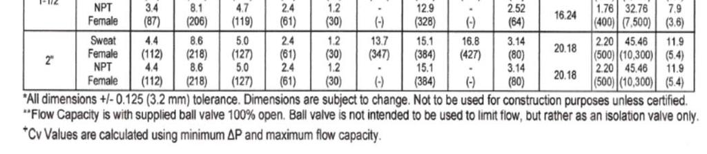
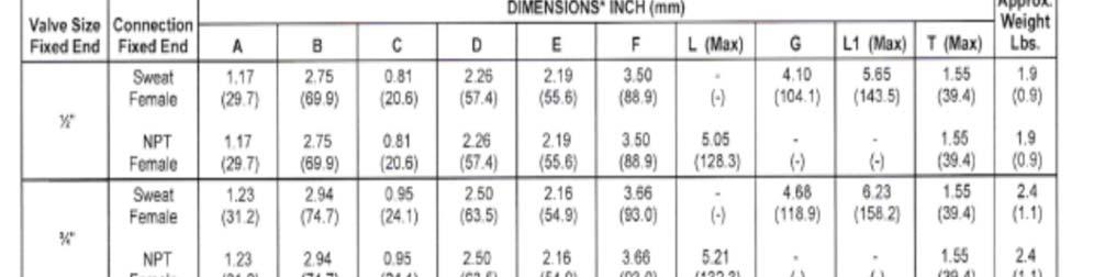
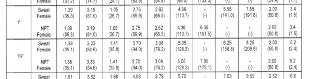
5 5 ChamFlex Single Hose Assembly provides you with superior fire retardant hose assemblies of unparalleled quality and integrity, designed specifically for hydronic hea ng and cooling systems. ChamFlex is a Class A fire rated hose assembly with fixed male pipe thread on one end and swivel with male pipe adapter on the other end. Our tube compound has been tested to, and awarded, a UL 94 V 0 fire ra ng, the highest standard in the industry. The patented process, which bonds the inner tube to a stainless steel wire outer braid minimizes the possibility of the hose assembly kinking during installa on. Assemblies for 1/2 and 3/4 hoses are available in a minimum length of six inches with increases of one inch. Minimum length for 1 and 1 1/4 hose is nine inches with one inch increments. In short ChamFlex provides you a hose with a long life of trouble free service. ChamFlex Hose Specifications: Braid: Tube Component: Fittings & Adapters: Temperature Range: Ratings: 302/304 Stainless Steel EPTF Santoprene Plated Steel -40 o F to 212 o F Class A Fire Rating ChamFlex 1/2 Hose ChamFlex 3/4 Hose ChamFlex 1 Hose ChamFlex 1 1/4 Hose Working Pressure 400 PSI 400 PSI 500 PSI 400 PSI Burst Pressure 1600 PSI 1600 PSI 2000 PSI 1600 PSI Minimum Bend Radius Hose O.D. (approx.)


6 ChamFlex Single Hose Assembly 6 ChamFlex hose: Fixed End x Swivel End w/ JIC Adapter ChamFlex hose: Swivel End x Swivel End w/ JIC Adapters Hose Assembly: Recognized by Underwriters Laboratories(UL) under UL 207. Tested to ASTM E84/UL 723 and received a Class A Fire Rating. This is the highest fire rating that can be obtained under this testing Methodology. Hose Sizes: 1/2 to 1-1/4 Hose Lengths: Standard: 12, 18, 24, 36 and 48 Custom: 1/2 & 3/4 - Minimum length: 6 with 1 increments. 1 & 1-1/4 - Minimum length: 9 with 1 increments. Inner Tube: EPTF - Santoprene with UL 94 V-0 Fire Rating Outer Braid: 302/304 Stainless Steel Fittings: Plated Steel Hose/Adapter Connection: All Metal JIC Flare Connection Fixed End Fitting: MNPT Swivel End Adapter Options: MNPT, FNPT(plated Steel), FSWT(brass) Suitable Media: Water and Glycol. Not rated for potable water ChamFlex Chemical Compatibility: For general compatibility inquiries, Chamberlin utilizes a chemical resistance guide for elastomers. This guide contains over 1000 listings and their general compatibility with our specific and unique tube component. Of course, compatibility varies with temperature and concentration, therefore the listings within this guide may be more general than the request. Actual compatibility can only be determined by the end user through testing under all extreme conditions and factors. The information below is offered only as a guide. Ethylene Glycol: A Rating to 70 F Propylene Glycol: A Rating to 70 F Methanol: A Rating to 70 F; +1% vol., 7 days, 70 F Ethanol: A Rating to 70 F WARNING: Flux and solder drips have been found to weaken the stainless steel braiding on Chamflex Hose Assemblies which could lead to deterioration of the inner tube component causing ballooning and eventual failure. Chamflex Hose Assemblies must be shielded with appropriate fire resistance materials or if possible, removed from service if soldering, welding, or brazing is to occur in areas above or adjacent to said assemblies. will not be responsible for failed hose assemblies and/or subsequent damage that occurred by failing to follow the provided Installation Instructions (and warnings) as well as the Safety Guide. NOTE: Be sure that the exterior of the hose does not come into contact with substances not compatible with 304 L stainless steel, including (but not limited to) any substances that contain chlorides. Chlorides have been found to cause stress corrosion cracking of the stainless steel braid and eventual failure. WARNING: To insure proper installation, this hose assembly must be installed according to instructions included with shipment. Instructions are also available online at
 Fitting: Size: 1/2 (5/8 OD) & 3/4 (7/8 OD) CTS Tube Connection Fitting: Brass Fitting Finish: Nickel plated Gripping Ring: Stainless Steel Specifications: Tube conforms")

7 7 ChamFlex Push To Connect (PTC) Hose Assemblies Spec. Data for Push to Connect (PTC) Fitting: Size: 1/2 (5/8 OD) & 3/4 (7/8 OD) CTS Tube Connection Fitting: Brass Fitting Finish: Nickel plated Gripping Ring: Stainless Steel Specifications: Tube conforms to ASSE 1061 IAPMO Listed Working Pressure: up to 200 psi Temperature Range: 0 F to 200 F NEW! Approved Tubing: ASTM B88 Tube Types K, L, M Drawn copper tube and annealed copper tube CPVC Water Tube per ASTM D M-99 Hose Size: 1/2 and 3/4 Hose Lengths: Standard: 12, 18, 24, 36 Custom: Minimum 6 with 1 increments Minimum Bend Radius: 2.5 Inner Tube: EPTF White Santoprene certified by Underwriters Laboratories (UL) under UL 94 V-0 Outer Braid: 302/304 Stainless Steel Hose Assembly: Recognized by Underwriters Laboratories (UL) under UL 207. Have also been tested to ASTM E84 /UL 723 and received a Class A Fire Rating. This is the highest fire rating that can be obtained under this testing methodology. Advantages of ChamFlex Push To Connect Hose Assemblies Minimal plumbing knowledge needed. 3 second connection. No tools needed for installation. (Just sandpaper to deburr pipe stub). Eliminates threaded adapter costs. No soldering on threaded adapters. No tightening of pipe thread unions. Easier installation in confined spaces. Installs easily on wet pipes, where soldering can be difficult PTC Fitting rotates on pipe to allow for easy installation of the other hose end and orientation of ball valves and other components. Replaces hard to match fittings just cut off the old fitting/deburr the cut pipe edge and push on the hose. Push To Connect Ball Valve Available in 1/2, 3/4 & 1 Working Pressue: 200 psi Temperature Range: 14 F 180 F


8 8 Advantages: ChamFlex Quick Connect System -Fewer Components. -Washer-less Design seating metal against metal -Reduces the number of brazed/soldered joints. -Fewer leak paths. -Great for applications with space constraints. -37 JIC flare connections seal with only finger tightening and about ¼ turn with wrenches. -37 JIC flare connections eliminate pipe thread connections which require 3 full revolutions of hard wrenching. -Less labor required for installation. 37 JIC Flare Ball Valve Available in 1/2 and 3/4 sizes. 37 JIC Brass Sweat Adapter Available in 1/2, 3/4, 1, & 1-1/4 sizes. Hose assemblies can be supplied with any combination of flare ball valve or brass sweat adapters.

9 9 Stainless Steel Braided All Metal Single Hose Assembly Hose Sizes: 1-1/2 to 2 Hose Lengths: Standard: 12, 18, 24, 36 Custom: Minimum length: 12 with 1 increments. Inner Tube: 321L/316L Stainless Steel Outer Braid: 304L Stainless Steel Fittings: Iron/Carbon Steel Fixed End Fittings: MNPT Union End Fittings: MNPT Working Pressure: 300 psi Burst Pressure: 1200 psi Minimum Bend Radius: 1-1/ Temperature Rating: -20 o F to 800 o F Suitable Media: Water and Glycol. Not rated for potable water WARNING: Flux and solder drips have been found to weaken the stainless steel braiding on Chamflex Hose Assemblies which could lead to deterioration of the inner tube component causing ballooning and eventual failure. Chamflex Hose Assemblies must be shielded with appropriate fire resistance materials or if possible, removed from service if soldering, welding, or brazing is to occur in areas above or adjacent to said assemblies. Chamberlin Rubber Company, Inc. will not be responsible for failed hose assemblies and/or subsequent damage that occurred by failing to follow the provided Installation Instructions (and warnings) as well as the Safety Guide. NOTE: Be sure that the exterior of the hose does not come into contact with substances not compatible with 304 L stainless steel, including (but not limited to) any substances that contain chlorides. Chlorides have been found to cause stress corrosion cracking of the stainless steel braid and eventual failure. WARNING: To insure proper installation, this hose assembly must be installed according to instructions included with shipment. Instructions are also available online at
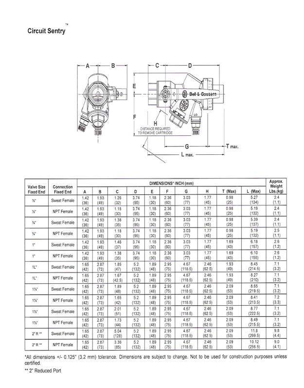
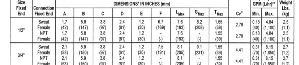
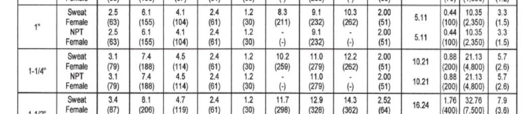
10 Model AC Circuit Sentry Automatic Balance Hose Kits 10 Return COIL Hose Kit #2 (or) Hose Kit #3 Supply Balance Type: Automatic Flow Limiting Valve with internal fixed flow cartridge Body Design: Brass Valve w/integrated isolation/shut-off, PT s, Union End on inlet side Body: Brass Ball: Chrome Plated Brass O-Rings: EPDM Max. Working Pressure: 400 psig Balance Cartridge A & B Body: Brass C Body: Stainless Steel Spring: Stainless Steel Diaphragm: EPDM Min. psid: Varies with size/cartridge Max. psid: 60
11 2.5 Model AC Circuit Sentry Automatic Balance Hose Kits 11 Return COIL Hose Kit #2 (or) Hose Kit #3 Supply Balance Type: Automatic Flow Limiting Valve with internal fixed flow cartridge Body Design: Brass Ball Valve + Model AC with PTs, union end on inlet side Body: Brass Ball: Chrome Plated Brass O-Rings: EPDM Max. Working Pressure: 400 psig Balance Cartridge: 304 Stainless Steel Spring: Stainless Steel Diaphragm: Reinforced EPDM Min. psid: Varies with size/cartridge Max. psid: 60 Cartridge Accuracy: +/- 5%
12 Model AC Circuit Sentry Automatic Balance Valve Flow Rates/Minimum PSID 12 "A" Body (1/2", 3/4", 1") Flow Rate Min. P "B" Body (1", 1-1/4", 1-1/2", 2") Flow Rate Min. P "C" Body (1-1/2", 2") Flow Rate Min. P


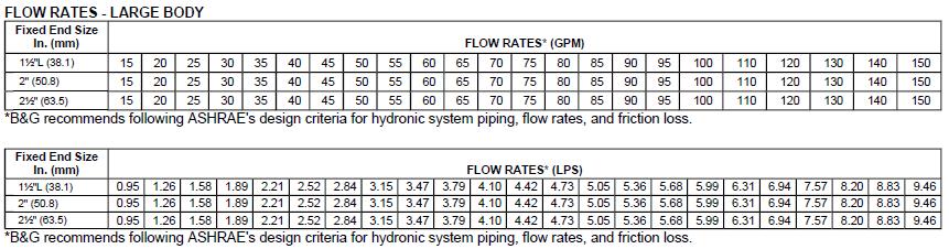
13 Model AC Circuit Sentry Automatic Balance Valve 13 Note: GPMs are rounded up to the next available GPM unless otherwise specified. Note: GPMs are rounded up to the next available GPM unless otherwise specified. Note: GPMs are rounded up to the next available GPM unless otherwise specified. Note: GPMs are rounded up to the next available GPM unless otherwise specified.
14 14
15 15
16 Model AM Flo-Setter Automatic Balance Hose Kits 16 Return COIL (or) Supply Balance Type: Automatic Flow Limiting Valve externally adjustable flow setting capability. Body Design: Brass Valve + Model AM w/pt s, External GPM dial Body: Brass Spring: Stainless Steel Diaphragm: HNBR O-Rings: EPDM Max. Working Pressure: 290 psig Min. psid: Varies with GPM setting Max. psid: 60
17 Model AM Flo-Setter Automatic Balance Hose Kits Flow Rates/Minimum PSID 17 1/2" Flow Rate Min. P Se ng Min Max. 1 1/4" Flow Rate Min. P Se ng Min Max. 3/4" Flow Rate Min. P Se ng Min Max. 1 1/2" Flow Rate Min. P Se ng Min Max. 1" Flow Rate Min. P Se ng Min Max. 2" Flow Rate Min. P Se ng Min Max.

18 18
19 Siemens PICV Automatic Balance Hose Kits 19 Return COIL (or) Supply Balance Type: PICV with adjustable max. flow setting & optional 3 Pt. floating or 0-10Vdc Actuator Body Design: Brass valve + PICV w/pt s, GPM dial. Body: Brass - ANSI 250 rating Spring: Stainless Steel Close Off: 1/2 & 3/4 Normally Open psi/ansi Class IV, 1/2 to 1-1/4 Normally Closed - 45 psi/ansi Class IV, 1-1/2 & Normally Closed - 50 psi/ansi Class III Flow Characteristic: 2-way, Linear Min. psid: varies with gpm setting Max. psid: 58 Actuators: Spring Return (Fail Safe): 24 volt 3 point floating or 24 volt 0-10Vdc Non-Spring Return (Fail-in-Place): 24 volt 3 point floating or 24 volt 0-10Vdc
20 Siemens PICV Automatic Balance Hose Kits Flow Rates/Minimum PSID 20 1/2" L Valve Action GPM Range Min P Max. P Norm. Closed Norm. Open /2 H Valve Action GPM Range Min P Max. P Norm. Closed Norm. Open /4 L Valve Action GPM Range Min P Max. P Norm. Closed Norm. Open ,5 58 3/4 H Valve Action GPM Range Min P Max. P Norm. Closed Valve Action GPM Range Min P Max. P Norm. Closed /4 Valve Action GPM Range Min P Max. P Norm. Closed /2 Valve Action GPM Range Min P Max. P Norm. Closed Valve Action GPM Range Min P Max. P Norm. Closed
21 Model MC Circuit Setter Manual Balance Hose Kits 21 Return COIL Hose Kit #4 (or) Hose Kit #5 Supply Balance Type: Body Design: Body: Ball: O-Rings: Max. Working Pressure: Required Pipe Diameters: Variable Cv Manual Balance with dial setting. Brass w/ dial control, PT s, Union End on inlet side. Brass Brass EPDM 300 psig (3) Upstream, (1) Downstream
22 22
23 Ball Valve Manual Balance Hose Kits 23 Return COIL Hose Kit #1 (or) Hose Kit #6 Supply Balance Type: Body Design: Body: Ball: Stem O-Rings: Stem Packing: Seat: Handle: Working Pressure: Manual Full Port Ball Valve w/pt & Memory Stop Brass Chrome Plated Brass Brass BUNA-N PTFE PTFE Zinc Plated Steel w/ Plastic Coating 600 psig
24 24
25 Model MV (Venturi) Manual Balance Hose Kits 25 Return COIL (or) Supply Balance Type: Body Design: Body: Ball: Stem: O-Rings: Seal: Handle: Working Pressure: Manual Venturi (fixed Cv) Venturi/Ball Valve combination with PTs, union end on inlet. Brass Chrome Plated Brass Explosion Proof EPDM Teflon Chrome Plated Steel 400 psig
 Manual")


26 26 Model MV (Venturi) Manual Balance Valve WARNING: To insure proper installation this product must be installed in conformance with applicable building codes. Use of proper torque wrench is required.
27 27


28 Model MVF (Circuit Setter) Manual Balance Hose Kit (Flanged) 28 Return COIL OR Supply Butterfly Valve Butterfly Valve, Strainer Balance Type: Venturi Type Manual Balance Circuit Setter Body Design: Flanged x Flanged Body: Carbon Steel 150# ANSI Flange Temp. Range: -4 F (-20 C) to 230 F (111 C) w/o Butterfly Valve, -4 F (-20 C) to 212 F (100 C) w/butterfly Valve Butterfly Valve: Body: Nodular Cast Steel 150# Flange Stem: Stainless Steel Disc: Aluminum/Bronze Liner: EPDM Spool Piece: Body: Cast Iron Gasket: Non-Asbestos Hose Specs. Design: Fixed Flange x Floating Flange Hose: 321 Stainless Steel Braid: 321 Stainless Steel Fixed Flange: Carbon Steel ANSI 150# Stub End: 304 Stainless Steel Working Pressure: 285 psig (2.5, 3 ), 260 psig (4 ), 210 psig (6 ) Strainer Specs. Design: Fixed flanged ends 150# with PT s and BDV Body: Cast Iron Screen: Stainless Steel 2-1/2-3 (10 Mesh), 4 and larger (5 Mesh) Working Pressure: 150 psig Butterfly ATC Specs. (Style 222) Body: Cast Iron, ASTM-A 126 Class B, 125#/150# ANSI Flanges Disc: 304 Stainless steel, ASTM-A 148 UNS C Grade A Stem: 416 Stainless steel, ASTM-A 582 UNS S41600 Molded-in Liner: EPDM (-40 F to 250 F) Inboard Bearings: Bronze Upper Bushings: Polyester Upper Stem Seal: NBR Actuators (G Series): Control: 2-1/2-4 : 2way and 3way Fail Safe (2Pos., Floating, 0-10Vdc, 0-420mA) 6 : 2way and 3way Non-Fail Safe (Floating, 0-10Vdc, 0-420mA) 8-10 : 2way and 3way Non-Fail Safe (2 Pos., Floating, 0-10Vdc, 0-420mA) Voltage: 2-1/2-6 : 24v 8-10 : Vac/Vdc NOTE: Flanged Hose Kits NOT Assembled. No Bolt or Gasket kits supplied.


29 Model MVB (Wafer Valve) Automatic Balance Hose Kit (Flanged) 29 Return OR 4 to 10 with Spool 2-1/2 to 3 w/o Spool COIL Butterfly Valve OR Supply Butterfly Valve, Strainer *No Strainer for 10 Balance Type: Wafer Valve with multiple fixed flow automatic balancing cartridges Body Design: Wafer Valve, mates to std. 150# ANSI Flanges Body: Ductile Iron Diaphragm: Reinforced EPDM Butterfly ATC Specs. Spring: Stainless Steel Body: Cast Iron, ASTM-A 126 Class B, 125#/150# ANSI Flanges O-Rings: EPDM Disc: 304 Stainless steel, ASTM-A 148 UNS C Grade A Max. Working Pressure: 150 psig Stem: 416 Stainless steel, ASTM-A 582 UNS S41600 Temp. Range: -4 F to 212 F Molded-in Liner: EPDM (-40 F to 250 F) Accuracy: +/- 5% Inboard Bearings: Bronze Butterfly Valve: Upper Bushings: Polyester Body: Nodular Cast Steel 150# Flange Upper Stem Seal: NBR Stem: Stainless Steel Actuators (G Series): Disc: Aluminum/Bronze Control: Liner: EPDM 2-1/2-4 : 2way and 3way Fail Safe (2Pos., Floating, 0-10Vdc, 0-420mA) Spool Piece: 6 : 2way and 3way Non-Fail Safe (Floating, 0-10Vdc, 0-420mA) Body: Cast Iron 8-10 : 2way and 3way Non-Fail Safe (2 Pos., Floating, 0-10Vdc, 0-420mA) Gasket: Non-Asbestos Voltage: Hose Specs. 2-1/2-6 : 24v Design: Fixed Flange x Floating Flange 8-10 : Vac/Vdc Hose: 321 Stainless Steel Braid: 321 Stainless Steel Fixed Flange: Carbon Steel ANSI 150# Stub End: 304 Stainless Steel Working Pressure: 285 psig (2.5, 3 ), 260 psig (4 ), 210 psig (6 ) Strainer Specs. Design: Fixed flanged ends 150# with PT s and BDV Body: Cast Iron Screen: Stainless Steel 2-1/2-3 (10 Mesh), 4 and larger (5 Mesh) Working Pressure: 150 psig NOTE: Flanged Hose Kits NOT Assembled. No Bolt or Gasket kits supplied.

30 30 Components Index also supplies additional valves and accessories that can be used as either substitutions or additions to the established hose kits. Strainers Ball Valves Unions ATC Zone Valves and Actuators ATC Ball Valves and Actuators 6-Way Control Valve (Ball Type Valve) - NEW
31 Model UBY Combination Ball Valve & Strainer (1/2-2 ) 31 Model UBY Combination Ball Valve & Strainer Body: Ball: Ball Seal: Stem: O-Rings: Strainer: Brass Full Port Chrome Plated PTFE Stainless Steel Explosion Proof EPDM 20 Mesh Stainless Steel Maximum Working Pressure: Maximum Operating Temp: 400 psig -4 o F to 250 o F Note: For a 2-1/2 kit a 2 UBY is supplied with a 2-1/2 NPT expanding coupler. WARNING: To insure proper installation this product must be installed in conformance with applicable building codes. Use of proper torque wrench is required.


32 32 UBY WARNING: To insure proper installation this product must be installed in conformance with applicable building codes. Use of proper torque wrench is required.
33 Ball Valve (1/2-2 ) 33 Ball Valve Manual Balance Valve Balance Type: Body Design: Body: Ball: Stem O-Rings: Stem Packing: Seat: Handle: Working Pressure: Manual Full Port Ball Valve w/pt Memory Stop Optional Brass Chrome Plated Brass Brass BUNA-N PTFE PTFE Zinc Plated Steel w/ Plastic Coating 600 psig WARNING: To insure proper installation this product must be installed in conformance with applicable building codes. Use of proper torque wrench is required.

34 CR 1000 Series PT Port Forged Brass Ball Valve 34
35 Model UBV Shut-Off Valve (1/2-2 ) 35 Model UBV Shut-Off Valve Body: C37000 Brass Ball: Chrome Plated Ball Seal: Teflon Stem: Explosion Proof O-Rings: EPDM Handle: Chrome Plated Steel w/ Plastic Cover Taps: Three Total 1/4 NPT - 1 Plugged - 1 Drain Valve - 1Pressure/Temperature Port Maximum Working Temperature: Temperature Range: 400 psig -4 o F to 250 o F WARNING: To insure proper installation this product must be installed in conformance with applicable building codes. Use of proper torque wrench is required.

36 36
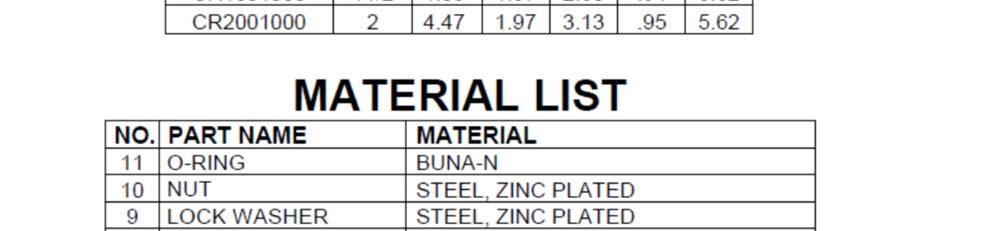
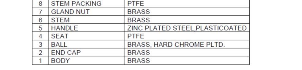
37 USA 9101 Series Forged Brass Ball Valve (1/2-2 ) 37 USA 9101 Series Forged Brass Ball Valve Body: End Cap: Ball: Seat: Handle: Stem: Gland Nut: Stem Packing: Lock Washer: Nut: O-Ring: Brass Brass Brass, Chrome Plated PTFE Zinc Plated Steel, Plasticoated Brass Brass PTFE Zinc Plated Steel Zinc Plated Steel Buna-N WARNING: To insure proper installation this product must be installed in conformance with applicable building codes. Use of proper torque wrench is required.


38 38 USA 9101 Series Forged Brass Ball Valve WARNING: To insure proper installation this product must be installed in conformance with applicable building codes. Use of proper torque wrench is required.
39 Model UA - Union Accessory (1/2-2 ) 39 Model UA - Union Accessory Body: Taps: O-Rings: C37000 Brass Two 1/4 NPT spaced 90 o apart EPDM Maximum Working Temperature: Temperature Range: 400 psig -4 o F to 250 o F Comes complete with Manual Air Vent and PT Port (as pictured) WARNING: To insure proper installation this product must be installed in conformance with applicable building codes. Use of proper torque wrench is required.
40 40
41 ATC Zone Valves 2-Way and 3-Way Zone Valves 41 AB A A AB Standard Features Line Sizes: 1/2-1 Body Style: Globe UL Listed for Plenum installations. All metal plug and seat. Direct coupled bonnet install actuator without tools. Standard 2.5 mm strike. Change from normally open to normally closed by simply changing actuators. Visual position indicator. Manual Override: 2 Position with auto lock, 3 Pt. Flt. & 0-10Vdc using hex wrench. B Valve Body Flow Characteristic: Linear Body: Brass Trim: Brass Stem: SS ASTM A582 type 303 O-Rings: EPDM Packing: EPDM O-rings Medium: Water, Glycol Solns. to 50% Medium Temp Range: 34 o F to 230 o F (1 o C to 110 o C) Max. Inlet Pressure: 125 psig Leakage Rate: ANSI Class III Close Off Ratings: ANSI/FCI 70-2, 2-way & 3-way valves 1/2-3/4 (44 psi), 1 (22 psi) 2 Position Actuators Voltage: 24 Vac +/- 20% Frequency: 24 Vac - 50/60 Hz Power Consumption: 9.8 VA Run Time: 10 seconds Nominal Stroke: 1/10-in. (2.5 mm) Nominal Force 24 lb. (105 N) Operating Temp: 41 o F to 122 o F (5 o F to 50 o C) Noise: <35 db Available CV s 2-Way: 1/2-1.0, 2.5, 4.0 3/ Way: 1/2-1.0, 2.5, 4.0 3/ Pt. Floating/ 0-10Vdc ACTUATORS (Non-Fail Safe) Voltage: 24 Vac +/- 20% Frequency: 24 Vac - 50/60 Hz Power Consumption: 3 Pt. Flt VA 0-10Vdc VA Run Time: 3 Pt. Flt sec., 0-10Vdc - 34 sec. Nominal Stroke: 1/10-in. (2.5 mm) Nominal Force: 24 lb. (105 N) Operating Temp: 41 o F to 122 o F (5 o F to 50 o C)
42 ATC Ball Valves 2-Way and 3-Way Ball Valves 42 Standard Features Line Sizes: 1-1/4-2 Body Style: Ball 1/4 turn rotary control valves designed to be coupled with an OpenAir actuator. Universal mounting plate accommodates different actuator sizes. Variety of ball sizes and flow coefficients. Actuator and plate can be rotated to facilitate installation and wiring. Standoffs and mounting plate provide thermal barrier between the actuator and valve. Plastic mounting plate, extension and handle do not condensate. Operating handle can be manually operate valve in event of power failure. Valve Body Flow Characteristic: Equal % Body: Brass Ball: Chrome Plated Brass Ball Seals: Glass-filled PTFE with EPDM O-rings Flow Optimizer: Glass-filled PTFE Stem: Brass, Double O-ring, Blow-out proof Stem Seals: Brass, Double O-ring, Blow-out proof Angle of Rotation: 0 to 90 degrees Medium: Water, Glycol Solns. to 50% Medium Temp Range: 35 o F to 250 o F (2 o C to 121 o C) Static Pressure/Temp: 360 psig/250 o F (600 WOG) Close Off Ratings: 200 psi for all 2-way, 200 psi for all 3-way Fail Safe Actuators Voltage: 24 Vac +/- 20% 24 Vdc +/- 15% Frequency: 50/60 Hz Power Consumption: 5 VA running, 4 VA holding Run Time: 90 seconds Spring Return: 15 sec. (typical) Running Torque: 62 lb. Enclosure: NEMA 1 3 Pt. Floating/ 0-10Vdc ACTUATORS (Non-Fail Safe) Voltage: 24 Vac +/- 20%, 15% Frequency: 50/60 Hz Power Consumption: 3.3 VA Run Time: 1-1/4 2-way & 3-way: 90 sec. 1-1/2-2 2-way & 3-way: 125 sec. Running Torque: 1-1/4 2-way & 3-way: 44 lb. 1-1/2-2 2-way & 3-way: 88 lb. Enclosure: NEMA 1
43 Belimo ATC Zone Valves 43 ATC Specs. - Body: Size? 2-1/2 Body: Forged brass, nickel plated Ball: Stainless Steel Stem: Stainless Steel Seats: PTFE Characterized Disc: Tefzel Packing: 2 EPDM O-rings, lubricated Body Pressure Rating: 400 psi Media Temp. Range: 0 o F to 250 o F Close Off Pressure: 100 psi Max. P: 50 psi for typical applications ATC Specs. - Actuator Power Supply 24 VAC +/- 20% 50/60 Hz Power Consumption: 5 W (running), 2.5 W (holding Control Type: 2 Position (on/off) Fail Safe: Spring Return (reversible CW/CCW mounting) Run Time: < 75 seconds (motor), o F to 122 o F, < o F Position Indicator: Visual indicator 0 o F to 95 o F (0 o F is full spring return position) Manual Override: 5mm hex crank (3/16 Allen) supplied Housing: Nema2, IP54, Enclosure Type 2
44 Siemens PICV Actuator 44 Actuators for: 1/2 to 1-1/4 Valve Bodies: Spring Return (Fail Safe): 24 volt 3 point floating or 24 volt 0-10Vdc Non-Spring Return (Fail-In-Place): 24 volt 3 point floating or 24 volt 0-10Vdc Features: Visual position indicator, manual override, direct mounting. Application: Heating or cooling applications, water/glycol solutions up to 50% in closed loops. Power: 24 Vac Operating Temperature: 41 o F to 122 o F 1-1/2 to 2 Valve Bodies: Non-Spring Return (Fail-In-Place): 24 volt 3 point floating or 24 volt 0-10Vdc Features: Visual position indicator, manual override, direct mounting. Application: Heating or cooling applications, water/glycol solutions up to 50% in closed loops. Power: 24 Vac Operating Temperature: 23 o F to 122 o F

:.3 to 4.")
45 6-Way Control Valve (Ball Valve Type) 45 The 6-Way Ball Valve in conjunction with modulating Actuator provides single valve and actuator changeover and control of hot and chilled water for heated/chilled beam applications or any 4-pipe system utilizing the same coil to heat and cool. Using the 6-Way Ball Valve in heated and chilled applications minimizes data points and decreases costs for the customer since only a single actuator is required. Valve Sizes: 1/2, 3/4, 1 Porting Connections: NPT Union, female connections Cv(s):.3 to 4.7 in various combinations for heated and chilled applications Cv Inserts: Stainless Steel Operating Pressure: 232 psi Close Off Pressure: 58 psi Differential Pressure: 29 psi Max. Leakage: 0%. Prevents hot and chilled water from mixing Temp. Range: 41 F to 194 F Valve Body: Hot-Pressed Brass CW 617N Ball Seals: low friction PTFE Medium: Water, water-glycol solns. Up to 50% Ball: Chrome Plated Brass Stem: Blowout proof. Stainless Steel Flow Characteristic: Linear Angle of Rotation: 0 to 90 Actuator Operating Voltage: 24 Vac Signal: 0 to 10 Vdc Failure Mode: Non-Spring return (Fail-in-place) Manual Override: Yes Power Consumption: 2 to 30 VA (Normal operation) Run Time: 90 seconds Agency Certification: UL meeting UL 873 cul: Certified to Canadian Standard C22.2 No Mounting Location: NEMA 1 (interior only)
46 Condensate Hose 46 Tube: Fittings: Clamps: 3/4 ID x 1/8 wall clear PVC White Nylon 3/4 NPT Stainless Steel Worm Gear Tube: Fittings: Clamps: 3/4 ID x 1/8 wall clear PVC White Nylon 3/4 NPT Stainless Steel Worm Gear Tube: Fittings: Clamps: Pan: Drain T : Outlet: 3/4 ID x 1/8 wall clear PVC White Nylon 3/4 NPT Stainless Steel Worm Gear 3/4 PVC Socket 3/4 Hose 3/4 MNPT
 fashion. Some expansion and contraction of the hose assembly can occur due to temperature variation, system pressures, and system cycling (see Figure #1).")
47 ChamFlex Fire Retardant Hose Assemblies Installation Instructions A) All applications should be checked to ensure that the proper hose assembly lengths are being installed: Hose assemblies should not be installed in a stretched (taut) fashion. Some expansion and contraction of the hose assembly can occur due to temperature variation, system pressures, and system cycling (see Figure #1). All hose assemblies should be routed properly to avoid contact with other surfaces that could possibly cause chafing (abrasion of the wire braided reinforcement). The use of elbows and adapters should be considered to relieve hose strain (see Figure #2). Do not use any plastic fittings or adapters. Hose assemblies should not be bent past the minimum bend radius requirements listed in the chart below. Hose assemblies showing evidence of kinking (being bent beyond the recommended bend radius) should not be installed (see Figure #3). 47 B) All hose assemblies should be installed in the following fashion so that no twisting occurs: Solid male pipe thread (NPT) ends should be installed first unless they are being connected to a swivel female (NPT). The entire hose assembly must rotate during the tightening of this connection in order to avoid hose tube damage. The flared adapter on the union (female swivel) end should be removed with the male pipe (NPT) end of the adapter connected to the appropriate port first. CAUTION: Thread sealant or thread tape should not be used on flared connections. Additional thread sealant or thread tape should not be applied to male pipe thread (NPT) ends where factory installed thread sealant is already present. The last step is to reconnect the flared swivel female coupling to the flared end of the adapter in a manner that ensures that the hose assembly is not twisted (see Figure #4). Visit to view safety guidelines for selecting hose. WARNING: Hoses are not rated for potable water WARNING: Flux and solder drips have been found to weaken the stainless steel braiding on Chamflex Hose Assemblies which could lead to deterioration of the inner tube component causing ballooning and eventual failure. Chamflex Hose Assemblies must be shielded with appropriate fire resistance materials or if possible, removed from service if soldering, welding, or brazing is to occur in areas above or adjacent to said assemblies. will not be responsible for failed hose assemblies and/or subsequent damage that occurred by failing to follow the provided Installation Instructions (and warnings) as well as the Safety Guide. NOTE: Be sure that the exterior of the hose does not come into contact with substances not compatible with 302/304 stainless steel, including (but not limited to) any substances that contain chlorides. Chlorides have been found to cause stress corrosion cracking of the stainless steel braid and eventual failure. CAUTION: When brass sweat adapters/valves are being used, make sure that the hose assembly is disconnected from the adapter prior to sweating it on. Excessive direct heat can damage the tube of the hose. The hose assembly should be reattached to the adapter after the sweating operation has been performed and adapter properly cooled. WARNING: To insure proper installation this hose assembly must be installed according to instructions.


48 48 To ensure the highest performance from your ChamFlex hose assemblies be sure they are installed properly. NO PIPE DOPE NO THREAD TAPE DO NOT PUT ANYTHING ON THE JIC FITTINGS DO NOT EXCEED BEND RADIUS ChamFlex hose assemblies have superior flexibility due to their unique construction but everything has its limits. Please refer to the installation instructions for the minimum bend radius of your hose assembly. PROTECT YOUR HOSE FROM FLUX & SOLDER ChamFlex hose assemblies will be damaged if flux & solder is allowed to drip onto them during installation. Be sure to protect your hose assemblies to prevent future problems. For more information visit our website:
49 Stainless Steel Braided All Metal Single Hose Assembly Installation Instructions A) All applications should be checked to ensure that the proper hose assembly lengths are being installed: 49 Hose assemblies should not be installed in a stretched (taut) fashion. Some expansion and contraction of the hose assembly can occur due to temperature variation, system pressures, and system cycling (see Figure #1). All hose assemblies should be routed properly to avoid contact with other surfaces that could possibly cause chafing (abrasion of the wire braided reinforcement). The use of elbows and adapters should be considered to relieve hose strain (see Figure #2). Do not use any plastic fittings or adapters. Hose assemblies should not be bent past the minimum bend radius requirements listed in the chart below. Hose assemblies showing evidence of kinking (being bent beyond the recommended bend radius) should not be installed (see Figure #3). Hose Size Working Pressure Minimum Burst (@ 72 o F) Temperature Range Minimum Bend Radius 1 1/2 300 PSI 1200 PSI -20 o F 800 o F PSI 1200 PSI -20 o F 800 o F PSI 1200 PSI -20 o F 800 o F 16 B) All hose assemblies should be installed in the following fashion so that no twisting occurs: Solid male pipe thread (NPT) ends should be installed first unless they are being connected to a swivel female (NPT). The entire hose assembly must rotate during the tightening of this connection in order to avoid hose tube damage. The male union end should be removed with the male pipe (NPT) end of the union connected to the appropriate port first. CAUTION: Thread sealant or thread tape should not be used on union connections. Additional thread sealant or thread tape should not be applied to male pipe thread (NPT) ends where factory installed thread sealant is already present. The last step is to reconnect the male union coupling to the female swivel hose end in a manner that ensures that the hose assembly is not twisted (see Figure #4). Visit to view safety guidelines for selecting hose. WARNING: Hoses are not rated or potable water WARNING: Flux and solder drips have been found to weaken the stainless steel braiding on Chamflex Hose Assemblies which could lead to deterioration of the inner tube component causing ballooning and eventual failure. Chamflex Hose Assemblies must be shielded with appropriate fire resistance materials or if possible, removed from service if soldering, welding, or brazing is to occur in areas above or adjacent to said assemblies. will not be responsible for failed hose assemblies and/or subsequent damage that occurred by failing to follow the provided Installation Instructions (and warnings) as well as the Safety Guide. NOTE: Be sure that the exterior of the hose does not come into contact with substances not compatible with 302/304 stainless steel, including (but not limited to) any substances that contain chlorides. Chlorides have been found to cause stress corrosion cracking of the stainless steel braid and eventual failure. CAUTION: When brass sweat adapters/valves are being used, make sure that the hose assembly is disconnected from the adapter prior to sweating it on. Excessive direct heat can damage the tube of the hose. The hose assembly should be reattached to the adapter after the sweating operation has been performed and adapter properly cooled. WARNING: To insure proper installation this hose assembly must be installed according to instructions.
50 Installation Instructions For PTC Hose Assemblies A) All applications should be checked to ensure that the proper hose assembly lengths are being installed: Hose assemblies should not be installed in a stretched (taut) fashion. Some expansion and contraction of the hose assembly can occur due to temperature variation, system pressures, and system cycling (see Figure #1). All hose assemblies should be routed properly to avoid contact with other surfaces that could possibly cause chafing (abrasion of the wire braided reinforcement). The use of elbows and adapters should be considered to relieve hose strain (see Figure #2). Do not use any plastic fittings or adapters. Hose assemblies should not be bent past the minimum bend radius requirements listed in the chart below. Hose assemblies showing evidence of kinking (being bent beyond the recommended bend radius) should not be installed (see Figure #3). B) All hose assemblies should be installed in the following fashion so that no twisting occurs: Solid male pipe thread (NPT) ends should be installed first unless they are being connected to a swivel female (NPT). The entire hose assembly must rotate during the tightening of this connection in order to avoid hose tube damage. The flared adapter on the union (female swivel) end should be removed with the male pipe (NPT) end of the adapter connected to the appropriate port first. 50 CAUTION: Thread sealant or thread tape should not be used on flared connections. Additional thread sealant or thread tape should not be applied to male pipe thread (NPT) ends where factory installed thread sealant is already present. The last step is to reconnect the flared swivel female coupling to the flared end of the adapter in a manner that ensures that the hose assembly is not twisted (see Figure #4). Specifications: Push-To-Connect Fitting Assembly Procedure 1. Using the appropriate tool, squarely cut the tubing 2. Remove burrs from the tube end 3. Mark insertion depth on tubing (for 1/2, insertion depth is 0.90 ; for 3/4, insertion depth is 1.20 ) 4. Insert tube into fitting and ensure insertion depth mark reaches the fitting button Tube end conforms to ASSE 1061 IAPMO Listed Working Pressure: up to 200 PSI Temperature Range: 0 0 F to F Approved Tubing: -ASTM B88 tube types K, L, M Drawn copper tube and annealed copper tube -CPVC water tube per ASTM D2846/2846M-99 -PEX water tube that meets the requirements of ASTM F876, F877 when using a tube support 5. Tubing removal can be accomplished with C shaped removal Visit to view safety guidelines for selecting hose. WARNING: Hoses are not rated for potable water WARNING: Flux and solder drips have been found to weaken the stainless steel braiding on Chamflex Hose Assemblies which could lead to deterioration of the inner tube component causing ballooning and eventual failure. Chamflex Hose Assemblies must be shielded with appropriate fire resistance materials or if possible, removed from service if soldering, welding, or brazing is to occur in areas above or adjacent to said assemblies. will not be responsible for failed hose assemblies and/or subsequent damage that occurred by failing to follow the provided Installation Instructions (and warnings) as well as the Safety Guide. NOTE: Be sure that the exterior of the hose does not come into contact with substances not compatible with 302/304 stainless steel, including (but not limited to) any substances that contain chlorides. Chlorides have been found to cause stress corrosion cracking of the stainless steel braid and eventual failure. Caution: When brass sweat adapters/ball valve are being used, make sure that the hose assembly is disconnected from the adapter prior to sweating it on. Excessive direct heat can damage the tube of the hose. The hose assembly should be reattached to the adapter after the sweating operation has been performed and adapter properly cooled. WARNING: To insure proper installation this hose assembly must be installed according to instructions.

51 51 GENERAL SAFETY NOTES: VALVE INSTALLATION, OPERATION AND SERVICE INSTRUCTIONS INSTALLER: PLEASE LEAVE THIS MANUAL FOR THE OWNER S USE WARNING: It is possible, depending on the age or condition of the product, for some liquid to escape when operating blow-down ball valves. Safety goggles should be worn while servicing the product. In this case, arrangements should be made to replace leaking valves. Failure to follow these instructions could result in serious personal injury. WARNING: Check for proper sealing when using as an isolation valve. If the seat is not sealing properly, liquid will continue to flow from the drain valves. In this case, arrangements should be made to replace leaking valves. Failure to follow these instructions could result in serious personal injury or death and property damage.
52 52 HOW TO USE PRESSURE TAPS TO MEAUSRE SYSTEM OPERATING CONDITIONS 1. Using Bell & Gossett s Model RP-250B readout probes, attach a Bell & Gossett differential pressure readout kit to the readout valves on the Accessory valve. WARNING: Hot water leakage can occur from readout valve during probe insertion and during hookup of readout kit. Follow the instruction manuals supplied with the readout probes and readout kit for safe use. Failure to follow this instruction could result in serious personal injury and/or property damage. 2. Read the differential pressure across the coil. This can be compared to system pump head to determine system flow blockage. 3. Differential pressure can also be taken at Circuit Setter, AFLV and Y-strainer. GENERAL INFORMATION: For Installing Sweat Connections: 1. Clean tube ends and valve connections thoroughly per good piping practices with a fine grade emery cloth or fine grit sandpaper. 2. For soldering, use 95-5 (Tin-Antimony) solder and a good grade of flux. 3. Use a torch with a sharp point flame. 4. When sweating the joints, first adjusting the valve in the full open position, then wrap the vale with a cool wet rag and then direct the flame with care to avoid subjecting the valve to excessive heat. Allow the valve to cool before torching or operating. 5. Check the soldering connection for leaks. WARNING: Use of improper procedures to sweat valve model with union connection into system can damage valve. Before installing sweat union connection to valve, remove the union nut and O-ring from the valve body, then union tailpiece with nut must be sweated (soldered) into place. Make sure the O-ring is reinstalled. Failure to follow this instruction could result in property damage and/or moderate personal injury. CAUTION: Heat associated with the use of silver solder may damage valve components and void the product warranty. Do Not use silver solder. Failure to follow these instructions could result in property damage and/or moderate personal injury. CAUTION: Excessive use of solder or flux may result in damage to the shutoff valve seat and ball. Do not use excessive solder or flux. Failure to follow these instructions can result in moderate personal injury and/or property damage. For Installing NPT Connections: Apply pipe compound conservatively to male connecting fittings only. After installation check all joints for leakage and retighten where necessary. CAUTION: The use of Teflon impregnated pipe compound and Teflon tape on pipe threads provides lubricity. Care should be taken to prevent over-tightening which may damage the valve body. Failure to follow these instructions can result in moderate personal injury and/or property damage. CAUTION: Do not use pipe dope where thread sealant is pre-applied when connecting valves to ChamFlex/All Metal SS Braided Hose Assemblies.
53 53 Model AC Circuit Sentry Automatic Flow Limiting Valve Description: The Automatic Flow-Limiting Valves (AFLV) are designed to automatically control the flow in piping systems to selected Preset limit. As pressure differential increases, a cartridge inside the valve body reduces the flow area to accurately maintain the Preselected flow rate. Installation Instructions: 1. The valves must be installed on the return side of the coil with union ended on the upstream side and other end on the downstream side. 2. Install the unit so that the flow arrow on the body housing points in the direction of flow. Operating Instructions: Operation of the Automatic Flow-Limiting Valves is fully automatic and does not require any adjustment. It automatically maintains the selected flow over the designed differential pressure range. CAUTION: Hot uninsulated surfaces can cause burns to the skin. Do not touch hot surfaces. Failure to follow these instructions could result in moderate personal injury. Before the system start up, remove cartridge from the valve. Flush the hydronic system and then reassemble cartridge into the valve and make sure cap is tightened properly. Start the system and check for the AFLV leak. How to use Automatic Flow-Limiting Valve Pressure Taps to Determine Proper Function of Valve: 1. Using Bell & Gosset Model RP-250B readout probes, attach a Bell & Gosset differential pressure readout kit to the readout valves on the Automatic Flow-Limiting Valve. 2. Read the differential pressure across the Automatic Flow-Limiting Valve. This can be compared to system pump head to determine valve function and system flow blockage. CAUTION: Hot water leakage can occur from read-out valve during probe insertion and during hookup of readout kit. Follow the instruction manual supplied with readout probe and kit for safe use. Failure to follow this instruction could result in serious personal injury and/ or property damage. Service Instructions: Should the Automatic Flow-Limiting Valve require cleaning or changing the orifice, follow the following instructions. WARNING: System fluid under pressure and/or at high temperature can be very hazardous. Before servicing reduce system pressure to zero or isolate the pressure reducing from the system. Leave drain valve open. Allow system to cool below 100 o F (38 o C). Failure to follow these instructions could result in serious personal injury or death and property damage. 1. Loosen and remove the cap from the valve body. 2. Pull the cartridge assembly from the valve body for cleaning or replacing with the new flow cartridge. Check the cartridge by pushing the orifice washer into the cartridge housing for several times to make sure spring is functional. 3. To change orifice washer (for a different flow valve). Remove the clip ring from inside the cartridge housing with a screwdriver. Pull the orifice washer out and replace with the new orifice size as required. 4. Reinstall retaining clip (or replace clip ring, if damaged) in the cartridge-housing groove. Slide cartridge into the body. Reassemble the cap with the O-ring to body with appropriate torque. WARNING: Corrosion or leakage is indication that the Automatic Flow-Limiting Valve must be replaced. Failure to follow these instructions could result in serious personal injury or death and property damage. WARNING: To ensure proper installation this product must be installed in conformance with applicable building codes. Use of proper torque wrench is required. PH: (585) Fax: (585) PO Box ~ Rochester, NY 14692
54 54 Model AM Flo-Setter Balance and Commissioning Valve Description: Bell & Gossett Model AM Flo-Setter Balance & Commissioning Valves are precision engineered valves used in heating and cooling systems for the distribution of flow in various sections of the system. The dynamic balancing and commissioning valve ensures easy and reliable balancing of the system, regardless of any fluctuations in the differential pressure of the system. The Bell & Gossett Circuit Sentry Flo-Setter limits the maximum flow in the system and can be sued in both variable and constant flow systems. The clear scale on the lockable handle ensures that flow setting is simple and user friendly while the integral P/T ports allow verification of pressure. Installation Instructions: Circuit Sentry Flo-Setter Balance & Commissioning valves are uni-directional valves and can be installed in most altitudes; however, they should be installed in a position to facilitate the ease of balancing the system. Be sure to install the Circuit Sentry Flo-Setter with the arrow pointing in the direction of flow. Circuit Balance valves with NPT Connections: Apply pipe compound conservatively to male connecting fittings only. Check connection for leaks. CAUTION: The use of Teflon impregnated pipe compound and Teflon tape on threads provides lubricity. Care should be taken to prevent over tightening of the valves which may damage the Circuit Sentry Flo-Setter. CAUTION: Do not use pipe dope where thread sealant is pre-applied when connecting valves to ChamFlex/All Metal SS Braided Hose Assemblies. Operation Instructions: How to use Bell & Gossett Circuit Sentry Flo-Setter Balance & Commissioning Valves for Pre-Set Flow Balancing: The Circuit Sentry Flo-Setter Balance & Commissioning Valve is easily set, and the pre-setting is read on the scale. The flow rate of the valve can be determined from the flow rate graphs for the valve dimension in question. See the flow rate graphs of the valve in the FLOW CURVE BOOK (G10092) or Submittal (A or A-611) for further information about the adjustment setting. Select the appropriate size Circuit Sentry Flo-Setter Balance & Commissioning Valve (normally line size) for the required GPM. Please note: The scale is for the adjustment of flow. If you want to close the branch line, use an isolation ball valve in conjunction with the Circuit Sentry Flo-Setter. The handle can be locked after adjustment. Remove the B&G logo cap and tighten with 5mm hexagonal key. How to use Bell & Gossett Circuit Sentry Flo-Setter to Proportional Balance System: The system is easily balanced by adjusting the pump according to the required differential pressure across the critical valve. When the differential pressure is available the system will automatically be balanced. How to use Bell & Gossett Circuit Sentry Flo-Setter Balance & Commissioning valves as Flow Meters: The flow through the valve can be identified by measuring the differential pressure p across the valve. If the measured differential pressure is above the mini- mum p, the flow is the one stated on the graph for the valve. If the measured differential pressure is below the minimum p, the flow can be found by using the formula below. Q = Cv x P Q Flow Rate GPM Service Instruction: Periodically inspect the Circuit Sentry Flo-Setter for signs of leakage or corrosion. Insulation: C v Flow Coefficient GPM/PSI P Differential Pressure PSI Bell & Gossett recommends that insulation be attached to the Circuit Sentry Flo-Setter after the system has been balanced. Note: Tape or other acceptable means should be sued to secure the insulation to the Circuit Sentry Flo-Setter Balance & Commissioning Valve. WARNING: To ensure proper installation this product must be installed in conformance with applicable building codes. Use of proper torque wrench is required. PH: (585) Fax: (585) PO Box ~ Rochester, NY 14692
55 55 Siemens PICV Automated Balance Valve Description: Siemens Pressure Independent Control Valves integrate three functions into a single device: control valve, adjustable flow limiter, and automatic pressure regulator. The 1/2 Normally Open valves have a 2.5 mm stroke, and a threated valve bonnet for use with SSD Electronic Valve Actuators. The 3/4 Normally Open and 1/2 to 1-1/4 Normally Closed valves have a 5mm stroke, and a threaded valve bonnet for use with SSD Electronic Valve Actuators. The 1-1/2 and 2 Normally Closed valves have a 6.5 mm stroke, and a threaded valve bonnet for use with SQD Electronic Valve Actuators. Feature: * Control valve with integrated pressure regulator and adjustable flow limiter P/T Ports Installation: * ANSI Class 250 valve body * 200 psi close-off with ANSI Class IV leakage (1/2 and 3/4 Normally Open) * 45 psi close-off with ANSI Class IV leakage (1/2 to 1-1/4 Normally Closed) * 50 psi close-off with ANSI Class III leakage (1-1/2 to 2 Normally Closed) * Linear Flow Characteristic * Stainless Steel Stem For 1/2 and 3/4 Normally Open Valves: The low-pressure P/T port (blue indicator ring) should be located on the downstream side of the valve. The high pressure P/T port (red indicator ring) will be located on the upstream or inlet side of the valve. For 1-1/2 and 2 Normally Closed Valves: The low-pressure P/T port (blue indicator ring) should be located closest to the end connection. The high-pressure P/T port (red indicator ring) will be located closest to the valve system. Presetting Adjustment: Prior to mounting the actuator, remove the black control knob cover from the valve to verify the valve is set to ordered flow setting. To change the valve flow setting see steps 2, 3 and 4 below. (Flow setting scales are in gallons per minute (gpm) on all valves); NOTE: When tightening the knurled nut, some force is required to reach the required physical stop; approximately an additional 1/2 to 3/4 extra turn after initial finger tight resistance is felt. WARNING: To ensure proper installation this product must be installed in conformance with applicable building codes. Use of proper torque wrench is required. PH: (585) Fax: (585) PO Box ~ Rochester, NY 14692
56 56 Siemens PICV (cont.) Mounting and Installation: Install the valve so the flow follows the direction of the arrow indicated on the valve body. For best performance, install the valve assembly with the actuator above the valve body. The valve and actuator can be installed in any position between vertical and horizontal. See Figure 1. Do not install the valve assembly with the actuator below horizontal or upside down. NOTE: Allow sufficient space for servicing the valve and actuator. Commissioning Notes: CAUTION: The Pressure Independent Control Valves must be open when flushing or pressure testing the system. Strong pressure impacts can damage closed Pressure Independent Control Valves. CAUTION: Differential pressure across the valve greater than 58 psi will result in damage to the pressure regulator. CAUTION: Hot uninsulated surfaces can cause burns to the skin. Do not touch hot surfaces. Failure to follow these instructions could result in moderate personal injury. WARNING: To ensure proper installation this product must be installed in conformance with applicable building codes. Use of proper torque wrench is required. PH: (585) Fax: (585) PO Box ~ Rochester, NY 14692
57 57 Model MC Circuit Setter Description: Circuit Setter Balance Valves are precision engineered valves which function as precise system balancing valves and highly accurate variable orifice flow meter. Installation Instructions: 1. The valve should be installed on the return side of the coil with the union end on the upstream side and other end on the downstream side (except on the bypass line). How to use Bell & Gossett Circuit Setter Balance Valves for Pre-Set Flow Balancing: All Circuit Setter Balance Valves within a common zone, circuit or system, with a common pump, are brought into balance with each other by establishing a common BALANCE GOVERNING HEAD LOSS as noted. CAUTION: Hot uninsulated surfaces can cause burns to the skin. Do not touch hot surfaces. Failure to follow these instructions could result in moderate personal injury. 1. Identify a zone within a given circuit or circuit within a given system with the highest head loss. 2. Establish the value of the head loss in feet of water. 3. Establish the corresponding required GPM. 4. Select the appropriate size Circuit Setter Balance Valve (normally line size) for the required GPM. 5. Using Side #1 of the V91483 Circuit Setter Balance Valve Calculator, set the degree of closure hairline in the red section of the Calculator of the 0 o setting for the appropriate size Circuit Setter and read the head loss opposite the require CPM. The setting for this Circuit Setter will remain 0 o. 6. Add the head loss in Step 5 to the head loss in Step 2 to establish the Balancing Governing Head Loss for the zone or circuit. 7. Subtract the required head loss for each zone circuit from the Balance Governing Head Loss in Step 6 to establish the head loss difference for each zone or circuit which is to be brought into balance with Step The head loss difference in Step 7 and the required GPM in Step 3 are lined up in the white section of Side #1 of the Calculator and the degree of closure for the specific Circuit Setter Balance Valve is shown under the degree of closure hairline in the red section of the Calculator for the appropriate size Circuit Setter. 9. Adjust the Circuit Setter by turning the red knob by hand on sizes 1/2 through 1, or by placing a wrench on the wrench flats provided on sizes 1 1/4 through 2 1/2 to the set position determined by the preceding procedure. WARNING: It is possible, depending on the age or condition of the stem seal, for some liquid to escape during Circuit Setter adjustment. Do not have eyes or face on a level with the sides of the Circuit Setter. Failure to follow this warning could result in serious personal injury. NOTES: Head loss in Steps 6 and 2 are a fixed head requirement the zone, circuit or system pump, as required, must overcome. Refer to the G95872 prewired tag packaged with the Circuit Setter Balance Valve and fill in the appropriate information. Attach the tag to the Circuit Setter for future reference. How to use Bell & Gossett Circuit Setters to Proportional Balance a System: 1. Open fully all Circuit Setters on a single pump system. 2. If more than one branch circuit is used, start the balance procedure by reading all of the flows to the units in a branch. Each unit (coil) should have its own Circuit Setter for flow balancing. Using Bell & Gossett RP-250B readout probes, sequentially attach a Bell & Gossett differential pressure readout kit to the readout valves on each Circuit Setter Balance Valve. WARNING: Hot water leakage can occur from readout valve during probe insertion and during hookup of readout kit. Follow the instruction manual supplied with the readout probes and readout kit for safe use. Failure to follow this instruction could result in serious personal injury and/or property damage. 3. Using Side-2 of the Bell & Gossett Circuit Setter Balance Valve Calculator, with the top hairline set on zero for the size Circuit Setter being read, read the flow corresponding to the pressure drop read with the read out kit. 4. Calculate the ratio of the actual flow to the design flow for each unit in the branch. This is the proportional flow rate. (Actual flow divide by design flow.) 5. Select the Circuit Setter with the lowest proportional flow rater. This Circuit Setter is left in the full open position. Every other Circuit Setter in the branch is then reset to the same proportional flow rate. WARNING: To ensure proper installation this product must be installed in conformance with applicable building codes. Use of proper torque wrench is required. PH: (585) Fax: (585) PO Box ~ Rochester, NY 14692
58 58 Manual Circuit Setter Cont. 6. If there are additional branches, repeat the steps in 3, 4 and 5 above for each branch. 7. After all branches have been proportionally balanced, measure the full open flows on the Circuit Setters installed on the risers. Calculate the proportional ration of each riser Circuit Setter and select the one with the lowest proportional ratio. This Circuit Setter is left fully open and the other riser Circuit Setters are adjusted to this same ratio as described in (5). 8. Adjust pump flow so that circuits are receiving their design flow. This can be accomplished by adjusting a Circuit Setter Balance Valve installed on the pump discharge or by changing the pump impeller size. IMPORTANT: Of a high degree of throttling of flow at pump discharge is required Bell & Gossett recommends that the pump impeller be sized to produce design flow. This will reduce electrical energy consumption. How to use Bell & Gossett Circuit Setter Balance Valves as Flow Meters: 1. Energize the zone, circuit and/or system pump(s) as applicable. 2. Using Bell & Gossett Model PR-250B Readout Probes, sequentially attach a Bell &Gossett differential pressure readout kit to the read out valves on each Circuit Setter Balance Valves. WARNING: Hot water leakage can occur from readout valve during probe insertion and during hookup of readout kit. Follow the instruction manual a supplied with readout probes and readout kit for safe use. Failure to follow this instruction could result in serious personal injury and/or property damage. 3. Read the differential pressure across the orifice of the Circuit Setter Balance Valve. 4. Using Side #2 of the Circuit Setter Balance Valve Calculator, set the hairline over the degree of closure as indicated by the part of the red plastic knob or indicator plate parallel to the degree of closure noted on the calibration plate, and read actual GPM flowing through the Circuit Setter opposite the gauge reading head loss noted in the white section of Side #2. NOTE: If the system contains a liquid with a specific gravity and/or viscosity higher or lower than that of water, apply the appropriate correction factor noted in these instructions to obtain the actual GPM for the system liquid. How to Bell & Gossett Circuit Setter Balance Valves as an Isolation Valve: 1. Move the adjustment knob or stem until the position indicator aligns with the closed position on the calibration plate. 2. Close the isolation valve on the other side of the equipment to be serviced. 3. Open the drain valve to drain the system between the Circuit Setter and the second isolation valve. WARNING: Check for proper sealing when using as an isolation valve. If the sea is not sealing properly, liquid will continue to flow from the drain valves. In this case, Circuit Setter must be isolated from the system and replaced. Failure to follow these instructions could result in serious personal injury or death and proper damage. How to use the Memory Stop feature: 1. Make the final degree of closure setting. 2. Loosen the memory stop locking screw in the slot on the top of the red knob. 3. Slide the memory stop screw in the slot (counter-clockwise for 1/2-1 sizes and clockwise for 1 1/4-2 1/2 sizes) until the screw stops. 4. Tighten the memory stop screw. Servicing Instructions: Periodically inspect the Circuit Setter for signs of leakage or corrosion. WARNING: Corrosion of leakage is indication that the Circuit Setter must be replaced. Failure to follow these instructions could result in serious personal injury or death and property damage. WARNING: To ensure proper installation this product must be installed in conformance with applicable building codes. Use of proper torque wrench is required. PH: (585) Fax: (585) PO Box ~ Rochester, NY 14692
59 59 Ball Valve Installation Instructions: 1. Ensure the pipeline is free of dirt of debris. Flush system if necessary. Foreign matter can damage valve or degrade performance. 2. Thoroughly clean pipe threads and apply thread dope to the male thread only. PTFE thread sealant is recommended for most applications. (Installer is responsible for selecting a sealant compatible with fluid). CAUTION: The use of Teflon impregnated pipe compound and Teflon tape on pipe threads provides lubricity. Care should be taken to prevent over-tightening which may damage the valve body. Failure to follow these instructions can result in moderate personal injury and/or property damage. Do not use pipe dope where thread sealant is pre-applied when connecting valves to ChamFlex/All Metal SS Braided Hose Assemblies. 3. Apply torque to the valve at wrenching flats nearest the end being assembled. Do not apply torque through the full length of the valve body as this may compromise the integrity of the body to end piece seal. Care should taken not to over tighten as this as this can cause distortion of the valve body and effect valve performance. Pipe wrenches should not be used on the valve as they can crush the body distorting the NPT thread. 4. A tight leak free joint can be obtained on valves 2 and under by rotating the valve 2 to 3 turns relative to the pipe, larger valves should be turned 1 1/2 to 2 turns. (Basic Dimensions, American National Standards Taper Pipe Threads, NPT ANSI B ) 5. After installation operate the valve through several full open to close cycles. Check tightness of stem packing. 6. For valves with NPT side taps assembly is the same as end connections. Tighten the mating part 2 to 3 turns past hand tight while holding the valve securely. The valve should be secured at the wrenching flats only. Applying a radical load on the main part of the body can distort it. Operation Instructions: The valve is opened by turning counterclockwise one quarter turn and close by turning clockwise. Valve state is indicated by the lever. A closed valve s lever is at 90 o to the valve axis. When the valve is open the lever lies along axis. CAUTION: Hot uninsulated surfaces can cause burns to the skin. Do not touch hot surfaces. Failure to follow these instructions could result in moderate personal injury. WARNING: To ensure proper installation this product must be installed in conformance with applicable building codes. Use of proper torque wrench is required. PH: (585) Fax: (585) PO Box ~ Rochester, NY 14692
60 60 Model MV Venturi/Ball Valve Combination Description: The Bell & Gossett Model MV is a combination calibrated balance, commissioning and positive shutoff valve for use in HVAC systems. An efficient brass venturi design provides accurate flow balancing with minimal system pressure loss. Valves are furnished with two readout valves (pressure and temperature ports), standard port ball valve with memory stop, and hanging ID tag for commissioning. A variety of end connections are available on both the fixed and union ends. Venturi/Ball valve provides highly accurate flow measurement capabilities. WARNING: Damage to the Venturi/Ball valve or failure of solder sealing joints may occur if these operational limits are exceeded. This can result in water leakage. Failure to follow this instruction can cause serious personal injury and/or property damage. Installation Instructions: For Installing Sweat Connections: 1. Clean tube ends and valve connections thoroughly per good piping practices with a fine grade emery cloth or fine grit sandpaper. 2. For soldering, use 95-5 (Tin-Antimony) solder and a good grade of flux. 3. Use a torch with a sharp pointed flame. 4. When sweating the joints, first adjusting the valve in the full open position, then wrap the valve with a cool wet rag and then direct the flame with care to avoid subjecting the valve to excessive heat. Allow the valve to cool before touching or operating. 5. Check the soldered connection for leaks. WARNING: Use of improper procedures to sweat valve model with union connection into system can damage valve. Before installing sweat union connection to valve, remove the union nut and O-ring from the valve body, then union tailpiece with union nut must be sweated (soldered) into place. Failure to follow this instruction could result in property damage and/or moderate personal injury. CAUTION: Heat Associated with the use of silver solder may damage a Venturi/Ball valve and void the product warranty. Do not use silver solder. Failure to follow these instructions could result in property damage and/or moderate personal injury. For installing NPT Connections: Apply pipe compound conservatively to male connecting fittings only. CAUTION: The use of Teflon impregnated pipe compound and Teflon tape on pipe threads provides lubricity. Care should be taken to prevent overtightening which may cause damage to the valve body. Failure to follow these instructions can result in moderate personal injury and/or property damage. CAUTION: Do not use pipe dope where thread sealant is pre-applied when connecting valves to ChamFlex/All Metal SS Braided Hose Assemblies. After installation check all joints for leakage and retighten where necessary. Operation Instructions 1. Energize the zone, circuit and/or system pump(s) as applicable. 2. Using Bell & Gossett Model RP-250B Readout Probes, sequentially attach a Bell & Gossett differential pressure readout kit to the readout valves on each Venturi/Ball valve. 3. Read the differential pressure across the orifice of the Venturi/Ball valve 4. Using the differential pressure data sheet #EP-600 of the Venturi/Ball to read the actual GPM. Example: The Venturi/Ball valve model 3/4 L. If the differential pressure across the orifice read at 46 W.C. the flow rate is 4 GPM. WARNING: Hot water leakage can occur from readout valves during probe insertion and during hookup of readout kit. Follow the instruction manual supplied with readout probes and read out kits for safe use. Failure to follow these instructions could result in serious personal injury or death and property damage. How To Use The Memory Stop Feature: 1. Make the final degree of closure setting. 2. Loosen the handle nut and rotate memory stop until against the body locking. 3. Tighten the handle nut. Service Instructions: Periodically inspect the Venturi/Ball valve for signs of leakage or corrosion. WARNING: Corrosion or leakage is indication, that the Venturi/Ball must be replaced. Failure to follow these instructions could result in serious personal injury or death and property damage. CAUTION: Hot uninsulated surfaces can cause burns to the skin. Do not touch hot surfaces. Failure to follow these instructions could result in moderate personal injury. WARNING: To ensure proper installation this product must be installed in conformance with applicable building codes. Use of proper torque wrench is required. PH: (585) Fax: (585) PO Box ~ Rochester, NY 14692
61 61 Y-Strainer Combination Valve Description: Y-strainer valves are of brass construction with an integrated ball valve, strainer, blow-down valve and union with tailpiece. Installation Instructions: 1. The valves must be installed on the supply side of the coil with filed end on the upstream side and other end on the downstream side. 2. When installing the Y-strainer valves space around the units must be provided to move the valve handle to the shutoff position and to move the strainer from the strainer body for cleaning. 3. The Y-strainer must be installed with the strainer chamber down to prevent air binding and also to allow accumulated dirt to be blown down from the strainer. Operation Instructions: Y-strainer can be used to isolate hydronic equipment for repairs and/or drain the system. To close the Y-strainer ball valve move the handle a quarter of a turn until the handle is perpendicular to the valve and piping. If Y-strainer pressure drop becomes excessive, accumulated dirt should be blown down through the blow-down line (if installed) to a drain. If a blowdown line is not installed see the service instructions for removing and cleaning the strainer. The Y-strainer have construction with an integrated ball valve will function as a service valve. Service Instructions: If excessive pressure drop is measured across the Y-strainer the internal strainer has collected dirt/debris and needs to be cleaned. Install blow-down line (hose), then open blow-down valve. If blowing down the strainer has not solved the pressure drop problem, the Y-strainer must be disassembled and strainer cleaned. WARNING: Failure to use proper hose connection to the blow-down valve may result in serious personal injury and property damage. To clean the strainer, isolated the Y-strainer by shutting off the ball valve on upstream and downstream of the Y-strainer. Allow the system to cool down to 100 o F (38 o C) or less. WARNING: Hot fluid and/or fluids under pressure are a safety hazard. Do not service the strainer while it is hot or under pressure. Failure to follow these instructions could result in serious personal injury or death and property damage. Using the appropriate size wrench remove the brass cap on the Y portion of the strainer. Grab and remove the strainer. Clean the strainer in water to remove collected debris. Reinstall the strainer and the strainer cap. Pressurize the system and check for strainer cap leaks. If noted, slightly tighten nut until leakage stops. Periodically inspect the Y-strainer for signs of corrosion or leakage. If corrosion or leakage is noted the Y-strainer must be replaced. WARNING: Corrosion or leakage is indication that the Y-strainer Combination Valve must be replaced. Failure to follow these instructions could result in serious personal injury or death and property damage. CAUTION: Hot uninsulated surfaces can cause burns to the skin. Do not touch hot surfaces. Failure to follow these instructions could result in moderate personal injury. WARNING: To ensure proper installation this product must be installed in conformance with applicable building codes. Use of proper torque wrench is required. PH: (585) Fax: (585) PO Box ~ Rochester, NY 14692
62 Abbreviations Index 62 Acronym P AFLV ANSI ASTM ATC BDV Cv EPTF FNPT FSWT GPM HNBR JIC KPA MAV MFR MNPT NC NO PICV PSI PSID PT PTFE UBY PTC Definition Differential Pressure Automatic Flow Limiting Valve American National Standards Institute American Society for Testing Materials Automatic Temperature Control Blow Down Valve Flow Co-efficient Ethylene Propylene Thermoplastic Rubber Female National Pipe Thread Female Sweat Gallons Per Minute Hydrogenated Nitrile Joint Industrial Committee Kilo Pascal Manual Air Vent Maximum Flow Recommendation Male National Pipe Thread Normally Closed Normally Open Pressure Independent Control Valve Pounds per Square Inch Pounds per Square Inch Gauge Pressure Taps Polytetraflouroethylene Union Ball Valve with Y Strainer Push To Connect

")
63 63 ChamFlex Single Hose Assemblies: ChamFlex Hose Assemblies & Kits Class A Fire Rated stainless steel braided hose assemblies and kits. Our tube component is tested to and awarded a UL 94 V-0 fire rating. ChamFlex hose: Fixed End x Swivel End w/ JIC Adapter ChamFlex Hose Kits: ChamFlex hose: Swivel End x Swivel End w/ JIC Adapters Return Valve Options: Model MC Circuit Setter Manual Balance Hose Kits Model AC Circuit Sentry Automatic Balance Hose Kits Ball Valve Manual Balance Hose Kits Model AM Flo-Setter Automatic Balance Hose Kits Siemens PICV Automatic Balance Hose Kits Model MV (Venturi) Manual Balance Hose Kits Supply Valve Options: (or) ChamFlex assemblies are custom-made in our warehouse to meet customer specifications. Minimum length for 1/2 and 3/4 hose is 6 with 1 increments. Minimum length for 1 and 1-1/4 hose is 9 with 1 increments. Call Scott Harding at (585) or Tim La Bar at (585) for more information PO Box Rochester, NY 14692
Hose Length Custom Length Supply Line Options Ball Valve w/ PT UBY Strainer w/ PT and BDV
 Model AC Circuit Sentry Automatic Balance Hose Kits - Submittal Hose Kit Size Flow Range *MFR Qty. 1/2".33-14 5 3/4".33-14 11 3/4" 5-50 11 1".33-14 20 1" 5-50 20 1-1/4" 5-50 30 **1-1/2" 5-50 44 **1-1/2"
CLASS A FIRE RATED HOSE ASSEMBLIES & KITS
 CLASS A FIRE RATED HOSE ASSEMBLIES & KITS PO Box 22700 ~ Rochester, NY 14692 Phone: (585) 427-7780 ~ Fax (585) 427-2429 www.chamberlinrubber.com TABLE OF CONTENTS 2 Page Number 4 Advantages of ChamFlex
Innovation + Quality. Valves, controls + systems Balancing and Control Valves
 Innovation + Quality Valves, controls + systems Balancing and Control Valves Balancing and Control Valves Catalog Hydrocontrol Static Balancing Valves Recomended flow rate chart 4 Hydrocontrol VTR Static
New Fan Coil Piping Packages
 New Fan Coil Piping Packages SO BUILT TOUGH, TOUGH. WE BUILT GUARANTEE TO LAST. IT. www.superiorrex.com Piping Packages Table of Contents General Notes and Legend... 3 Piping Package Code Descriptions
Table of Contents. Automatic Section A B V. Coil Piping Packages A B P P. Water Source Heat Pump Hose Kits A B H K
 Table of Contents Automatic Section Automatic Balance Valves Installation Operation Maintenance Instructions / Warranty Technical Information How To Order Coil Piping Packages Package Types How To Order
PIPING PACKAGES For Chilled and Hot Water Fan Coil Units
 WWW.KRUEGER-HVAC.COM PIPING PACKAGES For Chilled and Hot Water Fan Coil Units PROVIDING YOU WITH AIR DISTRIBUTION AND EQUIPMENT SOLUTIONS TABLE OF CONTENTS General Notes... 4 Code Descriptions... 5 Guide
PIPING PACKAGES TABLE OF CONTENTS
 PIPING PACKAGES TABLE OF CONTENTS ITEM PAGE General Notes and Legend........................................................ 3 Piping Package Code Descriptions & Diagrams VAV Products and HL, HP, VF, and
Innovation + Quality. Valves, controls + systems Balancing and Control Valves
 Innovation + Quality Valves, controls + systems Balancing and Control Valves Cocon Q Pressure independent control valve Product specification Size: L1 L2 H1 H2 ½, ½ LF 2.75 3.9 2.0 1.9 ¾ LF 2.9 4.2 2.0
New Fan Coil Piping Package. Redefine your comfort zone.
 New Fan Coil Piping Package PIPING PACKAGES Table of Contents General Notes and Legend...3 Piping Package Code Descriptions & Diagrams THB, THH and TVB Fan Coils...4 TVS Fan Coil, 2-Way...5 TVS Fan Coil,
DARTMOUTH COLLEGE DESIGN January 3, 2012 & CONSTRUCTION GUIDELINES
 SECTION 15100 VALVES PART 1 DESIGN DIRECTIVE 1.1 SUMMARY A. This Section includes general duty valves common to most mechanical piping systems, special duty valves are specified in individual piping system
Automizer Combination Control Valves
 Combination Control Valves Recommended Applications Where actuated valves and balancing valves are used to control the flow For VAV boxes, fan coil units and terminal boxes Where space is tight Absolute
Installation Operation & Maintenance Instructions
 Installation Operation & Maintenance Instructions Contents Please read the installation operation and maintenance instruction prior to using any of our components. Failure to follow the instructions may
Features Globe Valve 2-Way & 3-Way Assembly Features:
 Rev: 10/22/13 Features Globe Valve 2-Way & 3-Way Assembly Features: DG Series Automated Applications for Building Automation, Temperature Controls, HVAC Two-Way and Three-Way Assemblies Chilled Water Hot
PIC-V Valve... 1 Unimizer (1/2 to 3 )... 2 Unimizer (4 to 6 )... 3 Automizer... 4 MVP Valve... 5
... 2 Unimizer (4 to 6 )... 3 Automizer... 4 MVP Valve... 5") PERFORMANCE SPECIFICATIONS PIC-V Valve... 1 Unimizer (1/2 to 3 )... 2 Unimizer (4 to 6 )... 3 Automizer... 4 MVP Valve... 5 PIC-V Valve 1. PRESSURE INDEPENDENT ACTUATED BALL VALVES AND CARTRIDGE (PIC-V)
PERFORMANCE SPECIFICATIONS PIC-V Valve... 1 Unimizer (1/2 to 3 )... 2 Unimizer (4 to 6 )... 3 Automizer... 4 MVP Valve... 5 PIC-V Valve 1. PRESSURE INDEPENDENT ACTUATED BALL VALVES AND CARTRIDGE (PIC-V)
PP1 Series Piping Packages for VG1000 Series Ball Valves
 PP Series Piping Packages for VG000 Series Ball s Product Bulletin PP2xxxxx- Series, PP8xxxxx- Series Code No. LIT-20974 Issued August, 204 PP Series Piping Packages are designed to provide an easier way
HVAC. Products. TRI A FLO Automatic Cartridges PAGE 2. TRI Y FLO Strainer PAGE 3. TRI U FLO Accessory Union PAGE 4. CB Series Butterfly/Venturi PAGE 5
 HVAC TRI A FLO Automatic Cartridges TRI Y FLO Strainer TRI U FLO Accessory Union Products Automatic balancing valves.5 thru 108.0 in Brass, Stainless, PVC, CPVC, Titanium, Ceramic, Monel, and more PAGE
I-799/79V Coil Components
 WARNING Read and understand all instructions before attempting to install any Victaulic products. Depressurize and drain the piping system before attempting to install, remove, or adjust any Victaulic
Characterized Port -CP Three-Way Ball Valves
 Characterized Port Three Way Ball Valves Technical Instructions The Characterized Port (-CP) Series 3-way Ball Valves are coupled with our Type A actuators to provide three-way mixing or diverting flow
SECTION VALVES PART 1 -GENERAL
 SECTION 1571 0 VALVES PART 3- EXECUTION General Shut-off Valves Balancing Valves Drain Valves RELATED WORK Section 15430- Plumbing Specialties Section 15450- Plumbing Equipment PART 1 -GENERAL SCOPE This
Zone Valves and Parts (Honeywell)
") 28/11/14 B49 Zone Valves - Two Way Fan Coil Zone Valves and Parts (Honeywell) Two-way Fan Coil Valve, the VU53 high pressure zone valves are used to control the flow of hot or chilled water in commercial
28/11/14 B49 Zone Valves - Two Way Fan Coil Zone Valves and Parts (Honeywell) Two-way Fan Coil Valve, the VU53 high pressure zone valves are used to control the flow of hot or chilled water in commercial
Simple Set COMMERCIAL. Pressure Independent Control Valves 2 Way 1/2-2 02/16/18 COMMERCIAL
 The Bray Simple Set is a threaded pressure independent control (PIC) valve designed for a wide variety of hot water and chilled water control applications. The SS Series combines high rangeability control
pressure independent characterized control tm
 5 pressure independent characterized control tm valves (PICCV ) PICCV reacts to pressure variations, performing a continual balancing function to maintain system performance at varying loads. Wide range
Brown University Revised August 3, 2012 Facilities Design & Construction Standards SECTION HVAC&R VALVES
 SECTION 23 05 23 HVAC&R VALVES PART 1 - GENERAL 1.1 SUMMARY: A. Section includes valves for building services piping. 1.2 GENERAL VALVE APPLICATION REQUIREMENTS: A. Provide valve handle extensions that
VA, VF, and VS Series Direct Mounted Globe Valve Assemblies. Application. Features
 TAC 1354 Clifford Avenue P.O. Box 2940 Loves Park, Illinois 61132-2940 www.invensysibs.com Two-Way and Three-Way Globe Valve Assemblies with 220 lbf Linear (979 N) Spring Return DuraDrive Actuators Submittal
15100 VALVES. E. Section Building Automation and Control System Guidelines
 15100 VALVES PART 1: GENERAL 1.01 RELATED SECTIONS A. Section 15050 Basic Material and Methods B. Section 15545 Chilled Water System C. Section 15550 Heat Generation D. Section 15790 Coils E. Section 15955
COMBINATION PRESSURE REDUCING AND SOLENOID SHUTOFF CONTROL VALVES 2.01 COMBINATION RESSURE REDUCING AND SOLENOID SHUTOFF CONTROL VALVE
 PROJECT NAME LOCATION COMBINATION PRESSURE REDUCING AND SOLENOID SHUTOFF CONTROL VALVES INTRODUCTION This specification covers the design, manufacture, and testing of 1 in. (25 mm) through 36 in. (900
SECTION VALVES
 PART 1 GENERAL 1.1 RELATED DOCUMENTS A. Drawings and general provisions of the Contract, including General and Supplementary Conditions Specification Sections, apply to this Section. B. Related Sections:
IMPORTANT NOTE! Please take the time to read this instruction sheet. Disregarding these guidelines may adversely affect your piping components
 IMPORTANT NOTE! Please take the time to read this instruction sheet. Disregarding these guidelines may adversely affect your piping components GENERAL INFORMATION... Error! Bookmark not defined. O-RING
Technical Documentation Pressure Independent Characterized Control Valves (PICCV) Patented Effective December 2007
 Patented Effective December 2007") Technical Documentation Pressure Independent Characterized Control Valves (PICCV) Patented Effective December 2007 Belimo Project: 1100 Peachtree, Atlanta, Georgia Control Valve Product Range Electronic
Technical Documentation Pressure Independent Characterized Control Valves (PICCV) Patented Effective December 2007 Belimo Project: 1100 Peachtree, Atlanta, Georgia Control Valve Product Range Electronic
P2050S-030, 1/2, Electronic Pressure Independent Valve Stainless Steel Ball and Stem, Female NPT Ends
 P2050S-030, 1/2, Electronic Pressure Independent Valve Stainless Steel Ball and Stem, Female NPT Ends Application Water-side control of heating and cooling systems for AHUs and water coils. Equal Percentage/
599 Series 6-Way Ball Valves
 Technical Instructions Document No. 155-803 599 Series 6-Way Ball Valves Description The 599 Series 6-way ball valves couple with the Siemens GDE161.1P OpenAir modulating actuator to provide single valve
Valve Selection. 1. Function and service considerations
 1. Function and service considerations Valve Selection Selection Valves serve the purpose of controlling the fluids in building services piping. Valves are produced in a variety of design types and materials.
Installation, Operation and Maintenance Manual
 Installation, Operation and Maintenance Manual Technical Manual EH 1.2 General Information about valve sizing: Valves with a Full Port have an internal seat diameter that is the same as the nominal pipe
PRESSURE REDUCING CONTROL VALVE
 PRESSURE REDUCING CONTROL VALVE 06/08 Schematics Throttles to reduce high upstream pressure to constant lower downstream pressure Reducing setpoint is adjustable 2 (AOS) X P/L Standard Components 1 Main
SECTION METERS AND GAGES FOR HVAC PIPING
 PART 1 GENERAL 1.1 RELATED DOCUMENTS A. Drawings and general provisions of the Contract, including General and Supplementary Conditions Specification Sections, apply to this Section. 1.2 SUMMARY A. This
SECTION GENERAL-DUTY VALVES FOR PLUMBING PIPING
 SECTION 22 05 23 PART 1 - GENERAL 1.1 SUMMARY A. Work Included: 1. Valves, General 2. Gate Valves 3. Balancing Valves 4. Ball Valves 5. Swing Check Valves 6. Backflow Prevention Assemblies 7. Pressure
A. This Section includes general duty valves common to several HVAC piping systems.
 SECTION 23 05 23 - PART 1 - GENERAL 1.1 RELATED DOCUMENTS A. Drawings and general provisions of the Contract, including General and Supplementary Conditions and Division 01 Specification Sections, apply
SECTION Pressure & Temperature Control
 16 Pressure & Temperature Control ARMSTRONG PRODUCT CATALOGUE 70 Pressure Reducing s Pressure Reducing s Armstrong pressure reducing valves (PRVs) and temperature regulators help you manage steam, air
See our expanding selection of products on Product Portfolio
 See our expanding selection of products on www.fnw.com Product Portfolio Table of Contents Low Lead Products- Page 3 Ball Valves, Check Valves, Strainers, Water Hammer Arrestors Ball Valves, Brass - Page
A. American National Standards Institute: 1. ANSI Z Relief Valves for Hot Water Supply Systems.
 SECTION 220523 - PLUMBING VALVES PART 1 - GENERAL 1.1 SUMMARY A. Section Includes: 1. Ball valves. 2. Butterfly valves. 3. Swing check valves. 4. Spring loaded check valves. 5. Water pressure reducing
P1000 Series Pressure Independent Valves
 Code No. LIT-1900445 Issued January 29, 2014 P1000 Series Pressure Independent Valves Description P1000 Series Pressure Independent Valves are designed to regulate the flow of hot or chilled water and
SOLENOID CONTROL VALVE
 PROJECT NAME LOCATION SOLENOID CONTROL VALVE INTRODUCTION This specification covers the design, manufacture, and testing of 4 in. (100 mm) through 36 in. (900 mm) Control Valves PART 1 - GENERAL 1. Standard
SECTION PIPING SPECIALTIES PART 1 GENERAL 1.1 SUMMARY
 SECTION 230533 - PIPING SPECIALTIES PART 1 GENERAL 1.1 SUMMARY A. Section Includes: 1. Pressure gages. 2. Pressure gage taps. 3. Thermometers. 4. Thermometer supports. 5. Test plugs. 6. Static pressure
Mustang Series PRESSURE REDUCING CONTROL VALVE. M115 (Globe) M1115 (Angle) Schematic. Standard Components. Options & Accessories.
 M1115 (Angle) Schematic. Standard Components. Options & Accessories.") PRESSURE REDUCING CONTROL VALVE 02/09 Schematic Throttles to reduce high upstream pressure to constant lower downstream pressure Reducing setpoint is adjustable 2 (AOS) P/L Standard Components 1 Main Valve
PRESSURE REDUCING CONTROL VALVE 02/09 Schematic Throttles to reduce high upstream pressure to constant lower downstream pressure Reducing setpoint is adjustable 2 (AOS) P/L Standard Components 1 Main Valve
Electronic Ball Valve Guide Specifications
 Electronic Ball Valve Guide Specifications Control Valve Assemblies Ball Valve Bodies All ball valves used for modulating or floating (tri-state) control must be furnished with a stainless steel ball &
LEAD FREE * LFF115 (Globe) LFF1115 (Angle)
 LFF1115 (Angle)") ES-ACV-SB-LFF115_LFF1115 LEAD FREE * Pressure Reducing Control Valve Schematics Throttles to reduce high upstream pressure to constant lower downstream pressure Reducing setpoint is adjustable 2 (AOS)
ES-ACV-SB-LFF115_LFF1115 LEAD FREE * Pressure Reducing Control Valve Schematics Throttles to reduce high upstream pressure to constant lower downstream pressure Reducing setpoint is adjustable 2 (AOS)
COMMERCIAL. Product PRofile
 Product PRofile 2 PRODUCT OVERVIEW INtroduction At Bray International, Inc., our business is helping our customers with their flow control requirements. Our modular product line of butterfly, ball and
NETSIAN TECHNOLOGY VALVE SCHEDULE
 NETSIAN TECHNOLOGY VALVE SCHEDULE JOB NAME: St. Joe's Hospital - Sonntag Academic Pavilion Date: 10-19-11 1911 CALC. Cv FLOW @ VALVE CAPACITY 14 1.4 ACTUAL PRESS. VALVE SIZE GPM or PSI PRESS VALVE DROP
Table of Contents. SeaTechInc.com
 Table of Contents 1-2 Technical Information 3 Tubing for 35 Series 4-5 10 Series Fittings 6-11 35 Series Fittings and Valves 12 35 Series Quick Connect Manifold, Configuration Styles 13 35 Series Quick
Pressure Independent Control Series
 Pressure Independent Control Series Two-Way, Brass Valve Bodies, -Inch to 2-Inch, ANSI 250 to 1-1/4 Inch NC - to 1-1/4-Inch NO 1- to2-inch NO Description Features Application Product Numbers and Ordering
UNIVERSITY SERVICES ANNEX James Madison University Harrisonburg, Virginia State Project Code: Architect s Project Number:
 SECTION 230523 GENERAL DUTY VALVES FOR HVAC PIPING PART 1 - GENERAL 1.1 RELATED DOCUMENTS A. Provisions of the Contract and of the Contract Documents apply to this Section. 1.2 DEFINITIONS A. The following
High Pressure 2-way 2 1/2-6 Globe Valves
 Overview Datasheet High Pressure 2-way 2 1/2-6 Globe Valves Designed to work with either an electronic actuator with a 3/4-inch (20 mm) or 1-1/2-inch (40 mm) stroke, the two-way globe valves are available
Pressure Independent Control Valve Applications for Building Automation, Temperature Controls, and HVAC Two-Way Chilled Water Hot Water
 Rev: 08/19/2013 (ATiMX) Features Pressure Independent Control Valve Applications for Building Automation, Temperature Controls, and HVAC Two-Way Chilled Water Hot Water The Auto Touch Independent Max (ATiMX)
See Water Pressure Reducing Valves Catalog (PHBRWPRV) for more detailed information about the products in this section.
 for more detailed information about the products in this section.") See Catalog (PHBRWPRV) for more detailed information about the products in this section. Water pressure reducing valves PR (36LF) Series Residential and commercial applications The Apollo 36LF pressure
See Catalog (PHBRWPRV) for more detailed information about the products in this section. Water pressure reducing valves PR (36LF) Series Residential and commercial applications The Apollo 36LF pressure
PRESSURE REDUCING VALVE
 Schematic Throttles to reduce high upstream pressure to constant lower downstream pressure Low Flow By-Pass controls at low flows 4 PRESSURE REDUCING VALVE with LOW-FLOW BY-PASS FEATURE Main Line valve
PRESSURE REDUCING VALVE
 Schematic Throttles to reduce high upstream pressure to constant lower downstream pressure Low Flow By-Pass controls at low flows 4 PRESSURE REDUCING VALVE with LOW-FLOW BY-PASS FEATURE Main Line valve
See Water Pressure Reducing Valves Catalog (PHBRWPRV) for more detailed information about the products in this section.
 for more detailed information about the products in this section.") See Catalog (PHBRWPRV) for more detailed information about the products in this section. WATER PRESSURE REDUCING VALVES PR (36LF) SERIES RESIDENTIAL AND COMMERCIAL APPLICATIONS The Apollo 36LF pressure
See Catalog (PHBRWPRV) for more detailed information about the products in this section. WATER PRESSURE REDUCING VALVES PR (36LF) SERIES RESIDENTIAL AND COMMERCIAL APPLICATIONS The Apollo 36LF pressure
M-8100EP. Installation Guide ENGINEERED PLASTIC MANIFOLD SERIES. Introduction. A. Assemble Manifold Components
 Introduction The Pro Manifolds with Integrated adaptor are designed for use in Hydronic radiant panel heating and cooling applications. They are available in various sizes, configurations, and options
GBV-G Balancing Valves
 Ductile Iron ASTM A6, Grade 6-4-2 The Series GBV is a multi-turn, Y-style globe valve designed for accurate determination and control of fluid flow to circuits requiring precise balancing. Max. Working
2006 Product Range Overview. Belimo Project: One Bellevue Center, Seattle, Washington
 2006 Product Range Overview Belimo Project: One Bellevue Center, Seattle, Washington Actuator Product Range Spring Return TF 18 in-lb [2 Nm] Approx. 4.5 sq. ft. LF 35 in-lb [4 Nm] Approx. 8 sq. ft. NF
Size: 1/4 to 3. Material: 316 Stainless Steel, Carbon Steel,
 Size: 1/4 to 4 Material: 316 Stainless Steel, Carbon Steel, Alloy 20, Hastelloy C, Monel, Brass, SW, BW, BSPT, 150#, 300#, 600#, Flanged Pressure: Vacuum to 3000 PSI* -50 to 600 F* ASME B16.34 Design Bottom
3-way 1/2-2 Globe Valves
 Datasheet Overview Designed to work with either an electronic actuator with a 3/4-inch (20 mm) stroke, the three-way globe valves are available in ANSI Class 250 for normally closed or normally open action.
MS Application. Features. Proportional Valve Actuator General Instructions
 Proportional Valve Actuator Application The Proportional Valve Actuator is a non-spring return actuator used with proportional to 10 Vdc or 4 to 0 ma controllers and standard 1/" to 1-1/4" two-way and
Jones Stephens Corp. PlumBest LTConnections SECTION D - FITTINGS & VALVES. Brass Compression Fittings
 SECTION - FITTINGS & VALVES Brass Compression Fittings... 131-132 Chrome Plated Compression Fittings... 133 45 Flare Tube Fittings... 134-135 Space Heater & Gas Range Fittings... 136 Yellow Brass Pipe
A. Provide all HVAC specialties required to complete the installation of all HVAC systems. B. Manufacturers: Refer to individual product item.
 DIVISION 23 HEATING, VENTILATING, AND AIR CONDITIONING (HVAC) SECTION 23 05 02 PART 1 GENERAL 1.01 DESCRIPTION A. Provide all HVAC specialties required to complete the installation of all HVAC systems.
Pressure Independent Control Series
 Pressure Independent Control Series Two-Way, Brass Valve Bodies, 1/2-Inch to 2-Inch, ANSI 250 1/2 to 1-1/4 Inch NC 1/2- to 1-1/4-Inch NO 1-1/2 to2-inch NO Description Features Application Product Numbers
PRESSURE REDUCING VALVE
 Schematic Throttles to reduce high upstream pressure to constant lower downstream pressure Closes quickly when downstream pressure exceeds reduced pressure setpoint 3 PRESSURE REDUCING VALVE with SURGE
DWS 41. Installation Data 44 Performance Specs DWS & DW-PRV Series
 IRRIGATION Title Description Details Page Intro 3 2000 Series 4 Model 2000 Solenoid 1 3 12 Model 2000 Solenoid 4 8 15 Model 2030 Low Power Solenoid 1 3 17 Model 2030 Low Power Solenoid 4 8 19 Model 2160
Pressure Independent Control Series 2-Way Valves and Electronic Valve Actuators
 Pressure Independent Control Series 2-Way Valves and Electronic Valve Actuators Description The 1/2- to 1-1/4-inch Pressure Independent Control Valves have a 2.5, 5, or 5.5 mm stroke, and work with the
Terminator PICV. Technical Manual
 Terminator PICV Technical Manual Table of Contents Introduction 1 Advantages and Ease of Use 1 Applications examples 2 Technical specifications Start Up Charts 6 Start Up Charts 7 Start Up Charts 8 Flow
LEAD FREE * LFM115 (Globe) LFM1115 (Angle)
 LFM1115 (Angle)") ES-ACV-SB-LFM115_LFM1115 LEAD FREE * Pressure Reducing Control Valve Schematic Throttles to reduce high upstream pressure to constant lower downstream pressure Reducing setpoint is adjustable 2 (AOS) P/L
ES-ACV-SB-LFM115_LFM1115 LEAD FREE * Pressure Reducing Control Valve Schematic Throttles to reduce high upstream pressure to constant lower downstream pressure Reducing setpoint is adjustable 2 (AOS) P/L
PRESSURE INDEPENDENT CONTROL VALVES (epiv & PICCV )
") 7 PRESSURE INDEPENDENT CONTROL VALVES (epiv & PICCV ) Pressure independent valves compensate for pressure variations, performing a continual balancing function to maintain system performance at varying
7 PRESSURE INDEPENDENT CONTROL VALVES (epiv & PICCV ) Pressure independent valves compensate for pressure variations, performing a continual balancing function to maintain system performance at varying
Product Catalog. Precision Control DeltaPValves. guaranteed delta T 10-year warranty made in the USA
 Product Catalog Precision Control DeltaPValves guaranteed delta T www.flowcontrol.com 10-year warranty www.flowcontrol.com made in the USA P.O. Box 848 18715 141st Ave NE Woodinville, Washington 98072
Selection Guide. Vx-2x13-5xx-9-xx Series Vx-2x13-8xx-9-xx Series VB-2x xx Series. Schneider Electric Ball Valve Assemblies
 Vx-2x3-5xx-9-xx Series Vx-2x3-8xx-9-xx Series VB-2x3-500-9-xx Series Selection Guide Schneider Electric Ball Valve Assemblies The Schneider Electric VA, VF, and VS-2x3-xxx-9-xx series Ball Valve Assemblies
ATi Max Series. Pressure Independent Control Valves 2 Way 2-1/2-6
 The Auto Touch Independent Max (ATiMX) valve brings pressure independent control technology to valves up to 6 and flow rates up to 468 GPM. It is a state-of-the-art control valve combining a high quality/
SECTION GENERAL-DUTY VALVES FOR HVAC. A. Section includes valves for building services piping.
 SECTION 23 05 23 GENERAL-DUTY VALVES FOR HVAC PART 1 - GENERAL 1.1 SUMMARY A. Section includes valves for building services piping. 1.2 REFERENCES A. AGA Z21.22 (American Gas Association) - Relief Valves
Accessories/Kits Ball Valve Bracket Kit (includes bracket, mounting screws, shaft and handle)
") 599 Series Technical Instructions Document No. 155-703P25 VF 599-9 2-Way Ball s Description The 599 Series 2-way Ball s are coupled with OpenAir actuators to provide equal percentage flow control. The
599 Series Technical Instructions Document No. 155-703P25 VF 599-9 2-Way Ball s Description The 599 Series 2-way Ball s are coupled with OpenAir actuators to provide equal percentage flow control. The
BRASS BALL VALVES. CSA, UL, cul CGA 9.1 and FM Approved. Female NPT, Male NPT and Flare ends in various configurations from 3/8 to 1.0.
 195 Series Ball Valves BRASS BALL VALVES CSA, UL, cul CGA 9.1 and FM Approved. Female NPT, Male NPT and Flare ends in various configurations from 3/8 to 1.0. Hot forged brass body Blow-out nickel plated
PYTHON 1500 SERIES CONTROL VALVES. Pneumatic and Electric Actuated
 PYTHON 1500 SERIES CONTROL VALVES Pneumatic and Electric Actuated Table of Contents Features and Benefits... 3 Specifications, Weights, and Dimensions... 4-5 Trim Options and CV Values... 6 Pneumatic Actuators...
Henderson Engineers, Inc. SECTION GENERAL DUTY VALVES FOR PLUMBING PIPING PART 1 - GENERAL REQUIREMENTS
 SECTION 220523 - GENERAL DUTY VALVES FOR PLUMBING PIPING PART 1 - GENERAL REQUIREMENTS 1.1 SUMMARY A. This Section includes general duty valves common to most plumbing piping systems. 1. Special purpose
FILTERS, STRAINERS AND VALVES PRODUCT GUIDE
 FILTERS, STRAINERS AND VALVES PRODUCT GUIDE TEE FILTERS INLINE FILTERS BRASS FILTERS SPIN ON FILTERS OFF-LINE FILTRATION Y STRAINERS BASKET STRAINERS DUPLEX STRAINERS STRAINING ELEMENTS FRP STRAINERS DUAL
PRESSURE RELIEF / SURGE ANTICIPATOR CONTROL VALVE
 PROJECT NAME LOCATION PRESSURE RELIEF / SURGE ANTICIPATOR CONTROL VALVE INTRODUCTION This specification covers the design, manufacture, and testing of 2-1/2 in. (65 mm) through 18 in. (450 mm) Control
INSTRUCTIONS FOR INSTALLATION, START-UP, AND OPERATION
 30/8.5.1 INSTRUCTIONS FOR INSTALLATION, START-UP, AND OPERATION VKP PILOT OPERATED PRESSURE REDUCING VALVE 12501 Telecom Drive, Tampa, Florida 33637 1. Introduction The Class VKP pilot-controlled steam
VA-640GSX024P. Overview. Applications. Features & Benefits. Datasheet. Large Globe Valve Actuators
 VA-640GSX024P Datasheet Large Globe Actuators Overview The VA-640GSX024P Electronic valve actuators receive a 0 to 10 VDC or 4 to 20 ma control signal to proportionally control the valve. Applications
1.1 PURPOSE A. This section is intended to define the general installation and minimum product requirements for hydronic and steam valves.
 Date Description of Change Pages / Sections Modified ID 6/15/16 Entire document - mgl44 PART 1 - INTRODUCTION 1.1 PURPOSE A. This section is intended to define the general installation and minimum product
599 Series 2-Way Ball Valves
 599 Series 2-Way Ball s Technical Instructions Document No. 155-703P25 VF 599-9 Description The 599 Series 2-way Ball s are coupled with OpenAir actuators to provide equal percentage flow control. The
MILLCENTRIC FULL/100% POR T ECCENTRIC PLUG VALVE
 ISO 9001 CERTIFIED MILLCENTRIC FULL/100% POR T ECCENTRIC PLUG VALVE Suggested Specifications The Milliken criteria of quality, reliability, safety and value are embodied in the Millcentric Eccentric valve,
Introduction. Ball Valves. Valves D
 Introduction Ball D-163 Ball can control hot or chilled water up to 50% glycol solution in convectors, fan coil units, unit conditioners, radiation, reheat coils. High performance features include: Close-offs
Spring Achieve System Balance Without All The Spin. PICCV. Complete Details Inside!
 Spring 2005 Achieve System Balance Without All The Spin. PICCV Complete Details Inside! Valve Selection Has Never Been Easier! Simply choose the smallest PICCV that can satisfy the flow rate of your system.
SECTION (15110) - GENERAL DUTY VALVES FOR PLUMBING PIPING
 - GENERAL DUTY VALVES FOR PLUMBING PIPING") SECTION 22 05 23 (15110) - GENERAL DUTY VALVES FOR PLUMBING PIPING PART 1 GENERAL 1.01 SUMMARY A. Section Includes: 1. Valves. B. Related Sections: 1.02 REFERENCES 1. Section 22 05 53 (15075) Identification
SECTION 22 05 23 (15110) - GENERAL DUTY VALVES FOR PLUMBING PIPING PART 1 GENERAL 1.01 SUMMARY A. Section Includes: 1. Valves. B. Related Sections: 1.02 REFERENCES 1. Section 22 05 53 (15075) Identification
RESILIENT SEATED BUTTERFLY VALVES. Howell Valve & Automation. Toll Free: Howellvalve.com
 RESILIENT SEATED BUTTERFLY VALVES Howell Valve & Automation Toll Free: 1-888-469-3557 Howellvalve.com TABLE OF CONTENTS Description Page Index 2 Resilient Standard Features 3 ST Boot Series with BUNA-N
VALVES. A. Section HVAC Basic Materials and Methods. E. Section Building Automation and Control System Guidelines
 230523 VALVES PART 1: GENERAL 1.01 RELATED SECTIONS A. Section 230500 HVAC Basic Materials and Methods B. Section 230510 Chilled Water System C. Section 230520 Heat Generation D. Section 238216 Coils E.
NORTHWESTERN UNIVERSITY PROJECT NAME JOB # ISSUED: 03/29/2017
 SECTION 23 2123 - PUMPS PART 1 - GENERAL 1.1 RELATED DOCUMENTS A. Drawings and general provisions of the Contract, including General and Supplementary Conditions and Division 01 Specification Sections,
SECTION GENERAL-DUTY VALVES FOR PLUMBING PIPING
 SECTION 220523 - GENERAL-DUTY VALVES FOR PLUMBING PIPING PART 1 - GENERAL 1.1 RELATED DOCUMENTS A. Drawings and general provisions of the Contract, including General and Supplementary Conditions and Division
PRESSURE REDUCING CONTROL VALVES
 PROJECT NAME LOCATION PRESSURE REDUCING CONTROL VALVES INTRODUCTION This specification covers the design, manufacture, and testing of 1 in. (25 mm) through 36 in. (900 mm) Control Valves PART 1 - GENERAL
See our expanding selection of products on Product Portfolio
 See our expanding selection of products on www.fnw.com Product Portfolio Table of Contents Low Lead Products- Page 3 Ball Valves, Check Valves, Strainers, Water Hammer Arrestors Ball Valves, Brass - Page
ALTITUDE CONTROL VALVES FOR ONE WAY FLOW
 PROJECT NAME LOCATION ALTITUDE CONTROL VALVES FOR ONE WAY FLOW INTRODUCTION This specification covers the design, manufacture, and testing of 2 in. (50 mm) through 36 in. (900 mm) Control Valves PART 1
DO NOT INSULATE BELOW THIS LINE. * For sizes 1/2" to 1 1/2" add 2 1/2" to 'C' dimension.
 428 Jones Boulevard Limerick Airport Business Center Pottstown, PA 19464 Phone: (610)495-5131 ax: (610)495-5134 www.watsonmcdaniel.com PAGE 28 INSTRUCTION PART NO. 2315400 C.R.3500 REV. 10 SIZE C B CENTER
Distributed By: M&M Control Service, Inc
 Control Valves DESIGN & OPERATION Description A control valve is a device capable of modulating flow at varying degrees between minimal flow and full capacity in response to a signal from an external control
The Siemens 599 Series Ball Valve Portfolio simplifies installations and maximizes control usa.siemens.com/hvac
 Two-,Three-, and Six-Way Ball Valves The Siemens 599 Series Ball Valve Portfolio simplifies installations and maximizes control usa.siemens.com/hvac Ready for the Challenge With higher close-offs, a wider