BANKABLE VALVES Technical Catalogue August 2017
|
|
|
- Dana Lambert
- 5 years ago
- Views:
Transcription


1 NKLE VLVES echnical Catalogue ugust 7 web edition
2 he company Dana revini Fluid ower, part of the Dana group, was established in in Reggio Emilia where it has its head office. Dana revini Fluid ower manufactures hydraulic components and application packages: a very large range suited to several operational requirements and applications thanks to a strict interaction between mechanical, hydraulic and electronic components. Dana revini Fluid ower is among the top manufacturers in Italy and a major player in Europe and in the world. International presence Dana revini Fluid ower operates internationally with 5 branches all over the world placed in major industrialized countries: Italy, France, Germany, English, Romania, Holland, Finland, China, India, Singapore and the United States. he network is constantly expanding by opening new branches in just a few years. he branches are guided by managers that have an excellent knowledge of their own country. he advantages this brings are evident: Reduced delivery times thanks to the branches warehouses; Easy customization of products and systems basing on the customer s needs, thanks to the competence and professional skills of the branches own technical and servicing departments; Quick servicing; ready sales staff at hand and closer to the customers, which ensures high flexibility plus experience. he production facilities are located throughout Reggio Emilia, Ozzano Emilia (O), Noceto (R), Novellara (RE), Yancheng (province of Jiangsu, China) which was inaugurated in 9 and became operative since. Competitive Strategy Innovation combined with the focus on customers is the strength of the Dana revini Fluid ower brand, born from the forty-year-long experiences of ron, Hydr-pp, SM Hydraulik, Oleodinamica Reggiana, VS revini and revini Hydraulics. Dana revini Fluid ower proposes itself as a local hub, as it happened to E Electronics in 8 and O Oiltechnology in 9, in order to create a new Made in Italy global player in the world of hydraulics, increasingly more integrated with electronics. he purpose is still the development of a very large range of products forming together integrated packages able to meet various application needs. Our ten-year-long partnership relations with hundreds of customers all over the world are the best synthesis of Dana revini Fluid ower s operational philosophy. Sharing of know-how and several experiences have made Dana revini Fluid ower a more global company, more incisive in international markets and closer to its customers. roduct lines he product lines are numerous and well-structured aimed to cover every needs: a strong basis on which to develop the engineering of application packages and complete systems. he offer is improving in the direction of a solution supplier often developed in co-design with the customer, both for the mobile and industrial sector. Hydr-pp roduct Line: Hydraulic power packs and mini hydraulic packs (whether standard or customised), cartridge valves and solenoid valves, gear boxes and transmission components. S..M. Hydraulik roduct Line: xial piston pumps and motors for medium and high pressure, orbital motors. ron roduct Line: Directional, flow, on-off and proportional pressure control valves. Modular and cartridge valves, subplates and blocks. revini Hydraulics roduct Line: roportional directional valves, joysticks and electronic modules. E Electronics roduct Line: Sensors, load cells, boards and electronic controls via CN, display units, planarity indicators. VS revini roduct Line: Mono-block and modular mobile valves. O Oiltechnology roduct Line: Gear pumps and motors, flow dividers.
3 ankable valves able of contents ECHNICL INFORMION... CDC / CD / CX / CXQ - ON/OFF ND ROORIONL VLVES...4 Composition form...6 Inlet module units...8 Working sections... Intermediate element...45 Outlet module units...5 CXDH / CDH / CFS - RE ND OS COMENSED VLVES...54 Composition form...56 Inlet module units...57 Working sections...6 Outlet module units...76 MODULR ELEMENS Valves and modular elements...77 CCESSORIES Interface for proportional directional valves HV4...8 Mounting kit...84 Fixing feet...84 Calibrated diaphragms...86 Connectors...87 Coils HOW O ORDER...9 ELECROMGNEIC COMIILIY revini Fluid ower S.p.. ll rights reserved. Hydr-pp, SM Hydraulik, ron, revini Hydraulics, E Electronics, VS revini, O Oiltechnology, logos are trademarks or are registered trademarks of revini Fluid ower S.p.. or other companies of the revini Group in Italy and other countries. he technical features supplied in this catalogue are non binding and no legal action can be taken against such material. revini Fluid ower will not be held responsible for information and specifications which may lead to error or incorrect interpretations. Given the continuous technical research aimed at improved technical features of our products, revini Fluid ower reserves the right to make change that are considered appropriate without any prior notice. his catalogue cannot be reproduced (in while or in part) without the prior written consent of revini Fluid ower. his catalogue supersedes all previous ones. Use of the products in this catalogue must comply with the operating limits given in the technical specifications. he type of application and operating conditions must be assessed as normal or in malfunction in order to avoid endangering the safety of people and/or items. General terms and conditions of sale: see website he products shown on this catalog are parts of line. IE/NK-INDEX//5
4 ECHNICL INFORMION INRODUCION Read this instructions carefully before installation. ll operations must be carried out by qualified personnel following the instructions. he user must periodically inspect, based on the conditions of use and the substances used, the presence of corrosion, dirt, the state of wear and correct function of the valves. lways observe first the operating conditions given in datasheet of the valve. OIL VISCOSIY CCORDING O EMERURE E mm²/s HYDRULIC FLUID 5 Observe the recommendations given in the data sheet of the valve. Use only mineral oil (HL, HL) according to DIN 554. Use of other different fluids may damage the good operation of the valve ISO VG ISO VG 68 ISO VG 46 ISO VG VISCOSIY Observe the recommendations given in the data sheet of the valve.he oil viscosity must be in the range of mm²/s to 5 mm²/s. Recommended oil viscosity 46 mm /s ( mm /s for Cartridge valves) able : ISO viscosity grades ISO VG verage Kinematic-viscosity Viscosity kinematic limits grade viscosity 4 C 4 C min. max. ISO VG 9.. ISO VG ISO VG ISO VG C F ISO VG ISO VG ISO VG 9. Values used in the chart Oil viscosity according to temperature CONVERSION LE SSU / E / mm²/s SSU E mm²/s CONMINION Oil contamination is the main cause of faults and malfunction in hydraulic systems. brasive particles in the fluid erode or block moving parts, leading to system malfunction. he valves we are offering do not require filtering characteristics any higher than those needed for usual hydraulic components such as pumps, motors, etc. However, accurate filtering does guarantee reliability and a long life to all the system s hydraulic parts. Reliable performance and long working life for all oil-pressure parts is assured by maintaining the level of fluid contamination within the limits specified in the data sheet of the valve. Hydraulic fluid must also be cleaned properly before filling the hydraulic circuit, especially when commissioning a new system, as this is when the oil contamination generally peaks due to its flushing effect on the components, and the running-in of the pump. Maximum contamination level is required on datasheet of the valve according to ISO 446:999. In the following table there is the correspondence between ISO 446:999 and old standard NS 68 for information purpose: he standard ISO 446:999 defines the contamination level with three numbers that relate with the number of particles of average dimension equal or greater than 4 μm, 6 μm e 4 μm, in ml of fliuid. In following table there is a reference to reccomended contamination level and correspondence with old NS 68 standard. IE/NK-INRO//5
5 ECHNICL INFORMION able : Reccomanded contamination level. Oil filtration recommendations ype of system Cleanliness class recommended ype of valve NS 68 ISO 446 : 999 ( ) Systems or components operating at HIGH RESSURE > 5 bar (6 psi) HIGH DUY CYCLE LICIONS Systems or components with LOW dirt tolerance Systems or components operating at MEDIUM / HIGH RESSURE Systems and components with moderate dirt tolerance Systems or components operating at LOW RESSURE < bar (5 psi) LOW DUY CYCLE LICIONS Systems and components with GOOD dirt tolerance bsolute filtration micron rating ( ) 8 / 6 / / 7 / 4 9 / 8 / 5 - Contamination class NS 68: it is determined by counting the total particles of different size ranges contained in ml of fluid. bsolute filtration: it is a characteristic of each filter, it refers the size (in micron) of the largest sperical particle wich may pass through the filter. WORKING EMERURES mbient temperature range: -5 C to +6 C Fluid temperature range (NR seals): -5 C to +75 C hermal shocks can affect the performance and the expected life of the product, hence it is necessary to protect the product from these conditions. SE O-rings made in crylonitrile utadiene (NR) are normally fitted on the valves. he backup rings that protect the O-rings are also made in NR, or sometimes FE. oth the O-rings and the backup rings are suitable for the working temperatures mentioned above. In the case of fluid temperatures > 75 C, FKM seals must be used (identified with V variant). ELECRICL OWER SULY Solenoid valves coils are designed to operate safely in the voltage range of ±% of nominal voltage at max. 6 C ambient temperature. he combination of permanent overvoltage and very hot temperatures can stress the solenoid. herefore always a good heat dissipation and voltage level has to be assured. Faulty coils may only be replaced by new, interchangeable, tested compo- nents in original-equipment quality. efore removing a coil, voltage must be disconnected. When replacing the coil, be aware to insert O-Rings in order to avoid the entrance of water. INSLLION he mounting surface must feature surface quality specified in data sheet of the valve: for example for Cetop valves generally is required Ra.6μm and flatness. mm over mm length. Normally in cartridge valve for sealing diameters of the cavities, is required roughness Ra.6μm. he surfaces and openings in the assembly plate must be free from impurity or dirt. Make sure the O-Rings fit correctly in their seats. Fixing screws must comply with the dimensions and the strength class specified in the data sheet and must be tightened at the specified tightening torque. Complete the electrical wiring. For circuit examples and pin assignments, see the relevant datasheet. USE ND MINENNCE Observe the functional limits indicated in the technical catalogue On a periodic basis and based on the conditions of use, check for cleanliness, state of wear or fractures and correct performance of the valve. If the O-rings are damaged, replace them with those supplied by the manufacturer. o assure the best working conditions at all time, check the oil and replace it periodically (after the first working hours and then after every working hours or at least once every year). ttention: all installation and maintenance intervention must be performed by qualified staff. RNSOR ND SORGE he valve must be handled with care to avoid damage caused by impact, which could compromise its efficiency. In the case of storage, keep the valves in a dry place and protect against dust and corrosive substances. When storing for periods of more than 6 months, fill the valve with preserving oils and seal it. WRRNY ND SULY CONDIIONS For the general warranty and supply conditions, please consult the specific sales contract or the General terms and conditions of sale document IO Downloaded from the website: CONVERSION CHR ype SI units lternative units Conversion factor Force Newton (N) [kgm/s²] Kilogram force (kgf) kgf 9.87 N pound force (lbf) [lbf/s²] lgf N millimeter (mm) [ m] inch (in) in 5.4 mm Length meter (km) [ m] yard (yd) [ft] m.96 yd kilometer (km) [ m] mile (mile) [76 yd] mile.69 km orque Newton meter (Nm) pound force.feet (lbf.ft) lbf.ft.56 Nm ower kilowatt (kw) [ Nm/s] horsepower (hp) kw.4 hp metric horsepower (CV) kw.6 CV bar Ma bar ressure Megaascal (Ma) [ N/mm²] psi (lbf/ln²) Ma 45 psi ton/f/ln² ton/f/ln² 5.45 Ma Flow rate liter/min (l/min) UK gal/min UK gal/min l/min US gal/min US gal/min.785 l/min emperature Degrees Celsius ( C) Farenheit ( F) F.8 C+ IE/NK-INRO//5
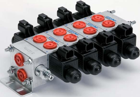
6 69 ON/OFF ND ROORIONL VLVES Introduction ankable ON/OFF directional control valves; ankable ROORIONL directional control valves; ankable ROORIONL COMENSED flow regulators; ON/OFF valves available in two sizes, with reduced overall dimensions or for high flow rates; vailable for parallel or series circuits; vailable with housing with threaded ports or interfaces for modular valves; vailable for Load Sensing circuits; ssemblable with FEH and FUH family inlet and outlet modules; ssemblable with CXDH and/or CDH family valves; ssemblable with revini HV valves (intermediate element required). Overall dimensions with CDC valves 46 Ch./Hex. 7 FE 9 9 FU D C No. elements C mm FE / FE Inlet module D mm C mm FE D mm IE/NK-ONOFF//5 4
7 69 46 Ch./Hex. ON/OFF ND ROORIONL VLVES Overall dimensions with CD valves FE FU D C No. elements C mm FE / FE Inlet module D mm C mm FE D mm IE/NK-ONOFF//5 5
8 Composition form CDC, CD, CX valves can be assembled with bankable valves CXDH - CDH - CFS (page 54) and with the proportional directional valves HV4 (catalogue roportional directional valves HV4 HV77 cod. 5) using the interface HSIF (page 8). How to order o order the assembly, specify the codes in progressive order (inlet, valves, outlet, mounting kit, feet). See example page 9. For any further special version not shown in this catalogue, please contact our echnical Department. IE/NK-ONOFF//5 6
9 Composition form Ref. ype Description age FE FE Inlet module units no pressure relief valve 8 Inlet module units with line no pressure relief valve 9 FE Inlet module units with pressure relief valve (up to l/min) FEQ Inlet module units with line, compensator and pressure relief valve 4 FE FE Inlet module units with pressure relief valve Inlet module units with line with pressure relief valve 4 5 FES Inlet module units with side ports and pressure relief valve 5 6 FEX Inlet module units with pressure relief valve for proportional pressure compensated flow regulator XQ 7 7 XQ ressure compensated flow regulator see catalogue Valves and Electronics code. 5 8 FE Inlet module units with pressure relief valve and electrical venting valve 9 9 FES Inlet module units with side ports, pressure relief valve and electrical venting valve CDC Directional control bankable valve with 9 coils CDC / CDCM (variants) CDM Directional control bankable valve with pressure relief valve and 9 coils 8 CDC / CDCM (variants) CD Directional control bankable valve with D5 coils CD (variants) 8 CX Solenoid operating proportional control bankable valves 9 4 CXQ Open loop proportional pressure compensated bankable flow regulators 4 5 FI Intermediate element 45 6 FIL Intermediate element with line 46 7 FIR Intermediate element with pressure reducing valve 47 8 CDCR Directional control valve connection - for Intermediate element FI 48 9 FI Intermediate element for valve CDCR 5 CD CDC CX ody G-H-M for modular valves FU Outlet module units 5 FU Outlet module units with side ports 5 FUS Outlet module units with overcenter and top port 5 4 V85 Intermediate element with flow regulator on and lines 77 5 CMF Modular elements with ports CM Modular pilot operated check bankable valves 79 7 CMM Modular max. pressure bankable valves 8 8 HSIF Interface for proportional directional valves HV4 8 9 Mounting kit 84 Fixing feet 85 Connectors 87 Coils 88 IE/NK-ONOFF//5 7
10 FE INLE MODULE UNIS NO RESSURE RELIEF VLVE Module units FE no pressure relief valve. hreaded ports ( and ), G/8 or 9/6-8UNF Maximum flow 4 l/min. luminum body. FEURES HYDRULIC SYMOL Max. operating pressure 5 bar Max. Flow 4 l/min Hydraulic fl uid DIN 554 Mineral oils Fluid viscosity 5 mm²/s Fluid temperature -5 C 75 C mbient temperature -5 C 6 C Max. contamination level (fi lter ß5 75) ISO 446:999: class /9/6 NS 68: class Weight. kg ORDERING CODE OVERLL DIMENSIONS FE Inlet module unit no pressure relief valve Size 5 7 ort sizes: G/8" 9/6-8UNF No variant V Viton Serial No n. 4 fori x OR - 9Sh 6.5 IE/FE// 8
11 FE INLE MODULE UNIS WIH LINE NO RESSURE RELIEF VLVE Module units FE with line, no pressure relief valve. hreaded ports ( and ) sizes G/8 and size G/4. Maximum flow 4 l/min. luminum body. FEURES HYDRULIC SYMOL Max. operating pressure 5 bar Max. Flow 4 l/min Hydraulic fl uid DIN 554 Mineral oils Fluid viscosity 5 mm²/s Fluid temperature -5 C 75 C mbient temperature -5 C 6 C Max. contamination level (fi lter ß5 75) ISO 446:999: class /9/6 NS 68: class Weight. kg ORDERING CODE OVERLL DIMENSIONS FE Inlet module unit no pressure relief valve with line 5 7 Size orts: G/8 (, ports) G/4 ( port) No variant V Viton Serial No N 4 Ø FE G /4" OR 7/- 9Sh OR 8/-8 9Sh IE/FE// 9
 sizes G/8 or 9/6-8UNF. Maximum flow l/min. luminum body. FEURES HYDRULIC SYMOL Max. operating pressure 5 bar Max.")
12 FE INLE MODULE UNIS WIH RESSURE RELIEF VLVE (U O L/MIN) Module units FE with CM-MC/MS adjustable pressure relief valve Manual adjustment with a grub screw. Fhreaded ports ( and ) sizes G/8 or 9/6-8UNF. Maximum flow l/min. luminum body. FEURES HYDRULIC SYMOL Max. operating pressure 5 bar Max. Flow l/min Hydraulic fl uid DIN 554 Mineral oils Fluid viscosity 5 mm /s Fluid temperature -5 C 75 C mbient temperature -5 C 6 C Max. contamination level (fi lter ß5 75) ISO 446:999: class /9/6 NS 68: class Weight.4 kg ressure relief valve (CM-MC/MS Setting range (): Spring Spring Spring Spring 4 max 5 bar max 9 bar max 9 bar max 9 bar () he minimum permissible setting pressure depending on the spring: see curves. ORDERING CODE RESSURE-FLOW RE MIN.SEING RESSURE FE C Inlet module unit (up to l/min) with pressure relief valve Size ort sizes: G/8" 9/6-8UNF djustment: C Grub screw Setting ranges 5 bar (white spring) 5 9 bar (green spring) 75 9 bar (yellow spring) bar (red spring) No variant V Viton Serial No. (bar) Q (l/min) 5 bar bar bar bar Fluid used: mineral based oil with viscosity 46 mm²/s at 4 C OVERLL DIMENSIONS 8.5 (bar) Q (l/min) CH max CH CH () Setting referred to the maximum pressure reached from the relief valve. Do not exceed the maximum working pressure 5 bar n. 4 fori 59 x OR - 9Sh 6.5 IE/FE//5
13 FEQ INLE MODULE UNIS WIH LINE, COMENSOR ND RESSURE RELIEF VLVE Module units FEQ with pressure compensator for fi xed displacement pumps and CM-MC/MS adjustable pressure relief valve on line Manual adjustment with a grub screw. Screw with orifice for bleeding. hreaded ports -, G/8 and, G/4. Maximum flow 4 l/min. luminum body. FEURES HYDRULIC SYMOL GRY GRX Max. operating pressure 5 bar Max. Flow 4 l/min Hydraulic fl uid DIN 554 Mineral oils Fluid viscosity 5 mm /s Fluid temperature -5 C 75 C mbient temperature -5 C 6 C Max. contamination level (fi lter ß5 75) ISO 446:999: class /9/6 NS 68: class Weight kg Ø.6 Ls Grano cieco lug ressure relief valve (CM-MC/MS Setting range (): Spring Spring Spring Spring 4 max 5 bar max 9 bar max 9 bar max 9 bar () he minimum permissible setting pressure depending on the spring: see curves. ORDERING CODE RESSURE COMENSOR FEQ C Inlet module unit (up to 4 l/min) with compensator and pressure relief valve Size orts: G/8 (, ports) - G/4 ( port) 9/6-8UNF (, ports) - 7/6 -UNF ( port) djustment: C Grub screw Setting ranges 5 bar (white spring) 5 9 bar (green spring) 75 9 bar (yellow spring) bar (red spring) No variant V Viton Serial No. (bar) Q (l/min) Fluid used: mineral based oil with viscosity 46 mm²/s at 4 C. o obtain a correct compensation the inlet fl ow must be 8% greater the sum of the regulated fl ow. () Setting referred to the maximum pressure reached from the relief valve. Do not exceed the maximum working pressure 5 bar. IE/FEQ//6
14 FEQ OVERLL DIMENSIONS 59 G /8" G /8" , OR 7/- 9Sh OR 8/-8 9Sh 59 N 4 Ø 6.5 IE/FEQ//5
15 FE INLE MODULE UNIS WIH RESSURE RELIEF VLVE Module units FE with CM adjustable pressure relief valve. Manual adjustment with a grub screw or plastic knob. hreaded ports - sizes G/8 or 9/6-8UNF. Maximum flow 4 l/min. luminum body. FEURES HYDRULIC SYMOL Max. operating pressure 5 bar Max. Flow 4 l/min Hydraulic fl uid DIN 554 Mineral oils Fluid viscosity 5 mm /s Fluid temperature -5 C 75 C mbient temperature -5 C 6 C Max. contamination level (fi lter ß5 75) ISO 446:999: class /9/6 NS 68: class Weight.6 kg ressure relief valve (CM...) Setting range (): Spring max 5 bar Spring max 5 bar Spring max bar () he minimum permissible setting pressure depending on the spring: see curves. ORDERING CODE RESSURE-FLOW RE MIN.SEING RESSURE FE Inlet module unit (up to 4 l/min) with pressure relief valve Size ort sizes: G/8 9/6-8UNF djustment: M lastic knob C Grub screw Setting ranges max. 5 bar (white spring) max. 5 bar (yellow spring) max. bar (green spring) No variant V Viton (bar) Q (l/min) Q (l/min) max 5 - bar - max 5 bar - max bar Fluid used: mineral based oil with viscosity 46 mm²/s at 4 C. OVERLL DIMENSIONS (bar) max Serial No. () Setting referred to the maximum pressure reached from the relief valve. Do not exceed the maximum working pressure 5 bar C Grub screw M lastic knob C CH n. 4 fori Ø 6.5 x OR - 9Sh 5.5 max 4 M IE/FE//
 with pressure relief valve and line FE..J6. Max. operating pressure 5 bar Max.")
16 FE INLE MODULE UNIS WIH LINE WIH RESSURE RELIEF VLVE Module units FE with line and CM adjustable pressure relief valve. Manual adjustment with a grub screw or plastic knob. hreaded ports -, G/8 and, G/4. Maximum flow 4 l/min. luminum body. FEURES HYDRULIC SYMOL ORDERING CODE FE FE.. Inlet module unit (up to 4 l/min) with pressure relief valve and line FE..J6. Max. operating pressure 5 bar Max. Flow 4 l/min Hydraulic fl uid DIN 554 Mineral oils Fluid viscosity 5 mm /s Fluid temperature -5 C 75 C mbient temperature -5 C 6 C Max. contamination level (fi lter ß5 75) ISO 446:999: class /9/6 NS 68: class Weight.6 kg ressure relief valve (CM...) Setting range (): Spring Spring Spring max 5 bar max 5 bar max bar () he minimum permissible setting pressure depending on the spring: see curves. Size orts: G/8 (, ports) G/4 ( port) djustment: M lastic knob C Grub screw OVERLL DIMENSIONS max Setting ranges max. 5 bar (white spring) max. 5 bar (yellow spring) max. bar (green spring) C No variant J6 With bleed V Viton N 4 Ø 6.5 Serial No. () Setting referred to the maximum pressure reached from the relief valve. Do not exceed the maximum working pressure 5 bar. 4 8 FE M RESSURE-FLOW RE MIN.SEING RESSURE 6.5 max x OR 7/- 9Sh (bar) (bar) OR 8/-8 9Sh Q (l/min) Q (l/min) max 5 bar - max 5 bar - max bar Fluid used: mineral based oil with viscosity 46 mm²/s at 4 C. C Grub screw M lastic knob IE/FE//5 4
 - G/ (). Maximum flow 4 l/min. luminum body. FEURES HYDRULIC SYMOL M Max. operating pressure 5 bar Max.")
17 FES INLE MODULE UNIS WIH SIDE ORS ND RESSURE RELIEF VLVE Inlet module units FES with side ports and CM adjustable pressure relief valve. Manual adjustment with a grub screw or plastic knob. hreaded ports -, G/8 or G/8 () - G/ (). Maximum flow 4 l/min. luminum body. FEURES HYDRULIC SYMOL M Max. operating pressure 5 bar Max. Flow 4 l/min Hydraulic fl uid DIN 554 Mineral oils Fluid viscosity 5 mm /s Fluid temperature -5 C 75 C mbient temperature -5 C 6 C Max. contamination level (fi lter ß5 75) ISO 446:999: class /9/6 NS 68: class Weight.6 kg ressure relief valve (CM...) Setting range (): Spring Spring Spring max 5 bar max 5 bar max bar () he minimum permissible setting pressure depending on the spring: see curves. ORDERING CODE RESSURE-FLOW RE MIN.SEING RESSURE FES Inlet module unit with side ports and pressure relief valve (up to 4 l/min) Size orts: G/8 ports, 5 G/8 port - G/ port djustment: M lastic knob C Grub screw Setting ranges max. 5 bar (white spring) max. 5 bar (yellow spring) max. bar (green spring) (bar) Q (l/min) Q (l/min) max 5 bar - max 5 bar - max bar Fluid used: mineral based oil with viscosity 46 mm²/s at 4 C. (bar) No variant V Viton Serial No. () Setting referred to the maximum pressure reached from the relief valve. Do not exceed the maximum working pressure 5 bar. IE/FES//5 5
18 FES OVERLL DIMENSIONS C 54 max x O-RING - 9Sh 6.5 max M G /8" G /4" C Grub screw M lastic knob IE/FES//5 6
19 FEX INLE MODULE UNIS WIH RESSURE RELIEF VLVE FOR ROORIONL RESSURE COMENSED FLOW REGULOR XQ Module units FEX for proportional pressure compensated fl ow regulator XQ. With CM adjustable pressure relief valve. Manual adjustment with a grub screw or plastic knob. hreaded ports - sizes G/8. Maximum flow 4 l/min. luminum body. FEURES HYDRULIC SYMOL XQ FEX Max. operating pressure 5 bar Max. Flow 4 l/min Hydraulic fl uid DIN 554 Mineral oils Fluid viscosity 5 mm /s Fluid temperature -5 C 75 C mbient temperature -5 C 6 C Max. contamination level (fi lter ß5 75) ISO 446:999: class 9/7/4 NS 68: class 8 Weight.6 kg ressure relief valve (CM...) Setting range (): Spring Spring Spring max 5 bar max 5 bar max bar () he minimum permissible setting pressure depending on the spring: see curves. ORDERING CODE RESSURE-FLOW RE MIN.SEING RESSURE FEX Inlet module unit (up to 4 l/min)for proportional pressure compensated fl ow regulator Size orts: G/8 ports, djustment: M lastic knob C Grub screw Setting ranges max. 5 bar (white spring) max. 5 bar (yellow spring) max. bar (green spring) No variant V Viton Serial No. (bar) Q (l/min) Q (l/min) max 5 bar - max 5 bar - max bar Fluid used: mineral based oil with viscosity 46 mm²/s at 4 C. (bar) () Setting referred to the maximum pressure reached from the relief valve. Do not exceed the maximum working pressure 5 bar. IE/FEX//5 7
20 FEX OVERLL DIMENSIONS 59 4 C XQ o order, see catalogue Valves and Electronics code. 5 x O-RING - 9Sh max M 6.5 max ISO 44 CEO/NG6,5,5 9 C Grub screw M lastic knob N 4 M5 4,5 IE/FEX//5 8
21 FE INLE MODULE UNIS WIH RESSURE RELIEF VLVE ND ELECRICL VENING VLVE Module units FE with CM adjustable pressure relief valve and electrical venting valve CR48N normally open supplied with emergency control. Manual adjustment with a grub screw or plastic knob. hreaded ports - sizes G/8 or 9/6-8UNF. ressure gauge M, G/4 Maximum flow 4 l/min. luminum body. Connector to be ordered separately, see page 87. HYDRULIC SYMOL ORDERING CODE FE Inlet module unit with pressure relief valve Electric venting valve Size ort sizes: G/8 9/6-8UNF djustment: M lastic knob C Grub screw Setting ranges max. 5 bar (white spring) max. 5 bar (yellow spring) max. bar (green spring) Voltage for the electric venting valve (ab. ) S No variants SV Viton Y ush button emergency (see page ) S Rotary emergency (see page ) J M Junior connection (see page 88) CX Deutsch connection with bidirectional diode (see page 88) Serial No. () Setting referred to the maximum pressure reached from the relief valve. Do not exceed the maximum working pressure 5 bar. M FEURES Max. operating pressure 5 bar Max. Flow 4 l/min Hydraulic fl uid DIN 554 Mineral oils Fluid viscosity 5 mm /s Fluid temperature -5 C 75 C mbient temperature -5 C 6 C Max. contamination level (fi lter ß5 75) ISO 446:999: class /9/6 NS 68: class Weight. kg ressure relief valve (CM...) Setting range (): Spring Spring Spring max 5 bar max 5 bar max bar Electrical venting valve (CR4..N..) Max. excitation frequency Hz Duty cycle % ED ype of protection (in relation to the connector usad) I65 () he minimum permissible setting pressure depending on the spring: see curves. ab. - Voltage - Coil 8W/W () L VDC M 4 VDC N 48 VDC.6 VDC Z () VDC RC X () 5 VDC RC W (4) Without coil () Connector to be ordered separately, see page 87; Coils technical data, see page 88; () With rectifier: 5 VC/5Hz - VC/6Hz () With rectifier: VC/5Hz - 4 VC/6Hz (4) erformance are guaranteed only using valves completed with F coil IE/FE// 9
22 FE DIGRMS - RESSURE RELIEF VLVE RESSURE-FLOW RE MIN.SEING RESSURE (bar) Q (l/min) (bar) Q (l/min) max 5 bar max 5 bar max bar Fluid used: mineral based oil with viscosity 46 mm²/s at 4 C. DIGRMS - ELECRICL VENING VLVE RESSURE DROS LIMIS OF USE (bar) 8 (bar) Q (l/min) 5 4 Q (l/min) Fluid used: mineral based oil with viscosity 46 mm²/s at 4 C. OVERLL DIMENSIONS SNDRD EMERGENCY C Grub screw M lastic knob VRINS S Emergency rotary Y Emergency with push button J M Junior CX Deutsch with diode 9 Ø,5 Corsa (Stroke) 8 max Ø Ø 9, IE/FE//
23 FES INLE MODULE UNIS WIH SIDE ORS, RESSURE RELIEF VLVE ND ELECRICL VENING VLVE Inlet module units FES with side ports, CM adjustable pressure relief valve and electrical venting valve CR48N normally open supplied with emergency control. Manual adjustment with a grub screw or plastic knob. hreaded ports - sizes G/8 ressure gauge M, G/4 Maximum flow 4 l/min. luminum body. Connector to be ordered separately, see page 87. HYDRULIC SYMOL ORDERING CODE FE S Inlet module unit with pressure relief valve Electric venting valve and side ports Size ort sizes: G/8 djustment: M lastic knob C Grub screw Setting ranges max. 5 bar (white spring) max. 5 bar (yellow spring) max. bar (green spring) Voltage for the electric venting valve (ab. ) S No variants SV Viton Y ush button emergency (see page ) S Rotary emergency (see page ) J M Junior connection (see page 88) CX Deutsch connection with bidirectional diode (see page 88) Serial No. () Setting referred to the maximum pressure reached from the relief valve. Do not exceed the maximum working pressure 5 bar. M FEURES Max. operating pressure 5 bar Max. Flow 4 l/min Hydraulic fl uid DIN 554 Mineral oils Fluid viscosity 5 mm /s Fluid temperature -5 C 75 C mbient temperature -5 C 6 C Max. contamination level (fi lter ß5 75) ISO 446:999: class /9/6 NS 68: class Weight. kg ressure relief valve (CM...) Setting range (): Spring Spring Spring max 5 bar max 5 bar max bar Electrical venting valve (CR4..N..) Max. excitation frequency Hz Duty cycle % ED ype of protection (in relation to the connector usad) I65 () he minimum permissible setting pressure depending on the spring: see curves. ab. - Voltage - Coil 8W/W () L VDC M 4 VDC N 48 VDC.6 VDC Z () VDC RC X () 5 VDC RC W (4) Without coil () Connector to be ordered separately, see page 87; Coils technical data, see page 88; () With rectifier: 5 VC/5Hz - VC/6Hz () With rectifier: VC/5Hz - 4 VC/6Hz (4) erformance are guaranteed only using valves completed with F coil IE/FES//6
24 FES DIGRMS - RESSURE RELIEF VLVE RESSURE-FLOW RE MIN.SEING RESSURE (bar) Q (l/min) (bar) Q (l/min) max 5 bar max 5 bar max bar Fluid used: mineral based oil with viscosity 46 mm²/s at 4 C. DIGRMS - ELECRICL VENING VLVE RESSURE DROS LIMIS OF USE (bar) 8 (bar) Q (l/min) 5 4 Q (l/min) Fluid used: mineral based oil with viscosity 46 mm²/s at 4 C. OVERLL DIMENSIONS SNDRD EMERGENCY C Grub screw M lastic knob VRINS S Emergency rotary Y Emergency with push button J M Junior CX Deutsch with diode 9 Ø,5 Corsa (Stroke) 8 max Ø Ø 9, IE/FES//6
25 CDC DIRECIONL CONROL NKLE VLVE WIH 9 COI Directional control bankable valve CDC with single or double solenoid. Centring achieved by means of calibrated length springs which immediately reposition the spool in the neutral position when the electrical signal is shut off. Different springs used for each spool to improve the valve performance. Emergency control. ody for parallel or series connections hreaded ports sizes G/8 or 9/6-8UNF (SE 6), with or without line. Coils protection I65 ower supply DC or C (with rectifier). Standard connectors DIN 465 ISO 44, M Junior, flying leads and Deutsch Maximum flow until l/min. Cast iron zinc plated body. Connector to be ordered separately, see page 87. ORDERING CODE FEURES CDC E Directional control bankable valve (with 9 coil) Size ody type (tab. ) Electrical operator Spool (tab.) Mounting (tab.) Max. pressure ports /// 5 bar Max. Flow l/min Max excitation frequency Hz Duty cycle % ED Hydraulic fluid DIN 554 Mineral oils Fluid viscosity 5 mm /s Fluid temperature -5 C 75 C mbient temperature -5 C 6 C Max. contamination level (filter ß5 75) ISO 446:999: class /9/6 NS 68: class Weight with one DC solenoid Weight with two DC solenoids.5 kg.5 kg Voltage (tab.4) Variants (tab.5) Serial No. Calibrated diaphragms on line, see page 86. IE/CDC//
26 CDC ORDERING CODE ab. - ody type Code ody orts G/8 parallel orts 9/6-8UNF parallel D () orts G/8 series E () orts 9/6-8UNF series ttachment style G arallel presetting for modular valves ttachment style H () Series presetting for modular valves L orts G/8 parallel - vers. ttachment style, parallel- vers. M resetting for modular valves Special connection -- S (see outlet module unit FUS pag.5) orts G/8 parallel - - closed U (not require the outlet module units) ab. - Standard spools wo solenoids,spring centred C Mounting Code Covering ransient position () - One solenoid, side E Mounting Code Covering ransient position () ab. - Mounting Code Symbol C E F G () H () ab.4 - Coils 9 voltage (7) Code Voltage Max. winding temperature (mbient temperature 5 C) Rated power W C (Ohm) ±7% L Vdc C 7 5. M 4 Vdc C 7. N () 48 Vdc C Z (4) Vdc C 7 9 () Vdc C X (5) 5 Vdc C W (6) Without coils ab.5 - Variants (7-8) Code Variant S No variant SV Viton LF () Emergency control lever (see page ) LR Emergency control lever 8 rotated (see page ) ES Emergency button (see page ) (9) Rotary emergency button (see page ) R5 (9) Rotary emergency b. 8 (see page ) First elem. for series connec. J () M Junior connection (see page 89) FL () Coil with flying leads 5 mm (see page 89) LD () Coil with flying leads mm and integrated diode (see page 89) CX () Deutsch connecection with bidirectional diode (see page 89) One solenoid, side F Mounting Code Covering ransient position () () For series connection configuration, a special individual bankable valve CDCE4 ( or G parallel body type only, with spool 4 type, variant) must always be used as first element. For other individual bankable valve must use body D E or H connector series type with spool 4 only. () Specials with price increasing () Special voltage (4) Require connector with rectifier: 5 VC/5Hz - VC/6Hz (5) Require connector with rectifier: VC/5Hz - 4 VC/6Hz (6) erformance are guaranteed only using valves completed with F coil (7) Connector to be ordered separately, see page 87; Coils technical data, see page 89; Voltage codes are not stamped on the plate, their are readable on the coils (8) Other variants available on request (9) ightening torque max. 6 9 Nm (CH n. ) () vailable in V or 4V DC voltage only () For the body type G - H - M order LR variant (Emergency control lever8 rotated) IE/CDC// 4
27 O O O O O O O O O O O O O O CDC HYDRULIC SYMO CDC... CDC... CDC D... CDC E... CDC G... CDC H... CDC L... CDC M... CDC S... CDC U... HYDRULIC SYMO ND INSRUCION OF CONNECION RLLEL CONNECION SERIES CONNECION Special element CDCE4 VM Special closing plug For series connection configuration, a special individual valve bank section (CDCE4) must always be used as first element (see ordering code page ). IE/CDC// 5
28 CDC RESSURE DROS - DIRECIONL CONROL NKLE VLVE (bar) Q (l/min) Spool Connections type / passing (p) (s) (p) (s) 5-6 (E) (F) Curve No. he diagram at the side shows the pressure drop curves for spools during normal usage. he fluid used is a mineral oil with a viscosity of 46 mm²/s at 4 C ; the tests have been carried out at a fluid temperature of 4 C. (p) arallel connections (s) Series connections (E) Mounting E (F) Mounting F LIMIS OF USE (MOUNING C-E-F) (bar) Q (l/min) 4 Spool type Curve No (4) (4) 5 and 6 spools used as or way, follow the curve No. 4 he tests have been carried out with solenoids at operating temperature and a voltage % less than rated voltage with a fluid temperature of 5 C. he fluid used was a mineral oil with a viscosity of 46 mm²/s at 4 degrees C. he values in the diagram refer to tests carried out with the oil flow in two directions simultaneously (e.g. from to and at the same time to ). In the cases where valves 4/ and 4/ are used with the flow in one direction only, the limits of use could have variations which may even be negative (See curve No 4 and Spool No 6 used as or ways). he tests were carried out with a counter-pressure of bar at port. NOE: he limits of use are valid for the C, E, F mounting. IE/CDC// 6
29 CDC OVERLL DIMENSIONS arallel body Only for versions O-Ring -8 9Sh x O-Ring - 9Sh 59 ody "S" connection , Single solenoid versions N x O-Ring - 9Sh N 4 Ø Manual emergency 9 Fittings, max. tightening torque 6 Nm arallel body resetting for modular valves IE/CDC// 7
30 O O O CDCM DIRECIONL CONROL NKLE VLVE WIH RESSURE RELIEF VLVE ND 9 COI Connector to be ordered separately, see page 87. ORDERING CODE Directional control bankable valve CDCM with single or double solenoid and one or two pressure relief valves with adjustable setting on and/or. Centring achieved by means of calibrated length springs which immediately reposition the spool in the neutral position when the electrical signal is shut off. Different springs used for each spool to improve the valve performance. Emergency control. ody for parallel or series connections hreaded ports sizes G/8 Coils protection I65 ower supply DC or C (with rectifier). Standard connectors DIN 465 ISO 44, M Junior, flying leads and Deutsch Maximum flow until l/min. Cast iron zinc plated body. CDCM Directional control bankable valve with relief valve (9 coil) E Size ody type (tab. ) Electrical operator Spool (tab.) Mounting (tab.) Voltage (tab.4) ressure relief valve setting on (tab. 5) ressure relief valve setting on (tab. 5, omitted if equal to ) FEURES Max. pressure ports /// 5 bar Max. fl ow l/min Max. fl ow - ressure relief valve see diagrams page Max excitation frequency Hz Duty cycle % ED Hydraulic fl uid DIN 554 Mineral oils Fluid viscosity 5 mm /s Fluid temperature -5 C 75 C mbient temperature -5 C 6 C Max. contamination level (fi lter ß5 75) ISO 446:999: class /9/6 NS 68: class Weight with one DC solenoid Weight with two DC solenoids.4 kg.65 kg Variants (tab.6) Serial No. Calibrated diaphragms on line, see page 86. HYDRULIC SYMO CDCM O.. CDCM.. CDCM N.. IE/CDCM//5 8
31 CDCM ORDERING CODE ab. - ody type Code ody O orts G/8 parallel with relief valve on orts G/8 parallel with relief valve on N orts G/8 parallel with relief valve on and ab. - Standard spools wo solenoids,spring centred C Mounting Code Covering ransient position ab.4 - Coils 9 voltage (6) Code Voltage Max. winding temperature (mbient temperature 5 C) Rated power W C (Ohm) ±7% L Vdc C 7 5. M 4 Vdc C 7. N () 48 Vdc C Z () Vdc C 7 9 () Vdc C X (4) 5 Vdc C W (5) Without coils () - One solenoid, side E Mounting ab.5 - ressure relief valve settings (7) Code Setting bar bar 5 bar Code Covering ransient position () One solenoid, side F Mounting ab.6 - Variants (6-8) Code Variant S No variant LF Emergency control lever (see page ) ES Emergency button (see page ) (9) Rotary emergency button (see page ) R5 (9) Rotary emergency b. 8 (see page ) J () M Junior connection (see page 89) FL () Coil with flying leads 5 mm (see page 89) LD () Coil with flying leads mm and integrated diode (see page 89) CX () Deutsch connecection with bidirectional diode (see page 89) Code Covering ransient position () ab. - Mounting Code C E F G () H () Symbol () Specials with price increasing () Special voltage () Require connector with rectifier: 5 VC/5Hz - VC/6Hz (4) Require connector with rectifier: VC/5Hz - 4 VC/6Hz (5) erformance are guaranteed only using valves completed with F coil (6) Connector to be ordered separately, see page 87; Coils technical data, see page 89; Voltage codes are not stamped on the plate, their are readable on the coils (7) Other settings available on request (8) Other variants available on request (9) ightening torque max. 6 9 Nm (CH n. ) () vailable in V or 4V DC voltage only IE/CDCM//5 9
32 CDCM HYDRULIC SYMO ND INSRUCION OF CONNECION RLLEL CONNECION DIGRMS - RESSURE RELIEF VLVES (bar) MX RESSURE SEING Q (l/min) (bar) MIN.SEING RESSURE Q (l/min) barbar bar 5 bar Fluid used: mineral based oil with viscosity 46 mm²/s at 4 C. RESSURE DROS - DIRECIONL CONROL NKLE VLVE (bar) Q (l/min) Spool Connections type / passing 8 (p) (p) (E) (F) Curve No. he diagram at the side shows the pressure drop curves for spools during normal usage. he fluid used is a mineral oil with a viscosity of 46 mm²/s at 4 C ; the tests have been carried out at a fluid temperature of 4 C. (p) arallel connections (s) Series connections (E) Mounting E (F) Mounting F LIMIS OF USE (MOUNING C-E-F) (bar) Q (l/min) 4 Spool type Curve No (4) he tests have been carried out with solenoids at operating temperature and a voltage % less than rated voltage with a fluid temperature of 5 C. he fluid used was a mineral oil with a viscosity of 46 mm²/s at 4 degrees C. he values in the diagram refer to tests carried out with the oil flow in two directions simultaneously (e.g. from to and at the same time to ). In the cases where valves 4/ and 4/ are used with the flow in one direction only, the limits of use could have variations which may even be negative (See curve No 4 and Spool No 6 used as or ways). he tests were carried out with a counter-pressure of bar at port. NOE: he limits of use are valid for the C, E, F mounting. (4) 5 and 6 spools used as or way, follow the curve No. 4 IE/CDCM//5
33 CDCM OVERLL DIMENSIONS x O-Ring - 9Sh Manual emergency N 4 Ø 6,5 6 Single solenoid versions 9,5 Fittings, max. tightening torque 6 Nm ,5 69,5 54,5 78,5 IE/CDCM//5
34 CDC / CDCM (variants) LF ND LR VRINS - EMERGENCY CONROL LEVER hanks to his flexibility, the component is designed to be inserted between the valve body and the spool, providing total interchangeability between the different types of solenoid body valves manufactured by revini Fluid ower. he control can be used as an emergency device in the event of power cuts. 6,5 77,5 LF variant HYDRULIC SYMOL Max operating pressure dynamic port static Max operating pressure port for series connection confi guration Mounting type Spools type CDC Weight with single solenoid CDCM Weight with double solenoid CDC CDCM 6 bar bar 6 bar C - F - H kg.6 kg.46 kg.6 kg 9 LR variant OHER VRINS ES Manual emergency Rotary emergency R5 Rotary emergency 8 J M Junior CX Deutsch with diode FL Flying leads LD Flying leads/diode Emergency and 5, tightening torque max. 6 9 Nm (CH n. ) IE/CDC-CDCM-VR//6

35 CD DIRECIONL CONROL NKLE VLVE WIH D5 COI Directional control bankable valve CD with single or double solenoid. Centring achieved by means of calibrated length springs which immediately reposition the spool in the neutral position when the electrical signal is shut off. Different springs used for each spool to improve the valve performance. Emergency control. ody for parallel or series connections hreaded ports sizes G/8 or 9/6-8UNF (SE 6), with or without line. Coils protection I66 ower supply DC or C (with rectifier). Standard connectors DIN 465 ISO 44, M Junior, flying leads and Deutsch Maximum flow until 4 l/min. Cast iron zinc plated body. Connector to be ordered separately, see page 87. ORDERING CODE FEURES CD E Directional control bankable valve (with D5 coil) Size ody type (tab. ) Electrical operator Spool (tab.) Mounting (tab.) Max. pressure ports /// bar Max. pressure port 5 bar Max. Flow 4 l/min Max excitation frequency Hz Duty cycle % ED Hydraulic fl uid DIN 554 Mineral oils Fluid viscosity 5 mm /s Fluid temperature -5 C 75 C mbient temperature -5 C 6 C Max. contamination level (fi lter ß5 75) ISO 446:999: class /9/6 NS 68: class Weight with one DC solenoid Weight with two DC solenoids.89 kg.778 kg Voltage (tab.4) Variants (tab.5) Serial No. Calibrated diaphragms on line, see page 86. IE/CD//
36 CD ORDERING CODE ab. - ody type Code ody orts G/8 parallel orts 9/6-8UNF parallel D () orts G/8 series E () orts 9/6-8UNF series ttachment style G arallel presetting for modular valves ttachment style H () Series presetting for modular valves L orts G/8 parallel - vers. ttachment style, parallel- vers. M resetting for modular valves Special connection -- S (see outlet module unit FUS pag.5) orts G/8 parallel - - closed U (not require the outlet module units) ab. - Standard spools wo solenoids,spring centred C Mounting Code Covering ransient position () - One solenoid, side E Mounting Code Covering ransient position () One solenoid, side F Mounting Code Covering ransient position () ab. - Mounting Code Symbol C E F G () H () ab.4 - Coils D5 voltage (7) Code Voltage Max. winding temperature (mbient temperature 5 C) Rated power W C (Ohm) ±% L Vdc C 4.8 M 4 Vdc C 8.8 V () 8 Vdc C 5.6 N () 48 Vdc C 75. Z (4) Vdc C 4 () Vdc C 87 X (5) 5 Vdc C 75 W (6) Without coils ab.5 - Variants (7-8) Code Variant S No variant SV Viton LF () Emergency control lever (see page 8) LR Emergency control lever8 rotated (see page 8) ES Emergency button (see page 8) (9) Rotary emergency button (see page 8) R5 (9) Rotary emergency b. 8 (see page 8) First elem. for series connec. J () M Junior connection (see page 9) D () M Junior and integr diode (see page 9) SL () Coil with flying leads 75 mm (see page 9) CZ () Deutsch D4- connection (see page 9) R6 () Deutsch D4- connection ecoat surface treatment (see page 9) RS () Hirschmann coil ecoat surface treatment (see page 9) () For series connection configuration, a special individual bankable valve CDE4 ( or G parallel body type only, with spool 4 type, variant) must always be used as first element. For other individual bankable valve must use body D E or H connector series type with spool 4 only () Specials with price increasing () Special voltage (4) Require connector with rectifier: 5 VC/5Hz - VC/6Hz (5) Require connector with rectifier: VC/5Hz - 4 VC/6Hz (6) erformance are guaranteed only using valves completed with F coil (7) Connector to be ordered separately, see page 87; Coils technical data, see page 9-9; Voltage codes are not stamped on the plate, their are readable on the coils (8) Other variants available on request (9) ightening torque max. 6 9 Nm (CH n. ) () vailable in V or 4V DC voltage only. () vailable in V, 4V, 8V or V DC voltage only () For the body type G - H - M order LR variant (Emergency control lever8 rotated) IE/CD// 4
37 O O O O O O O O O O O O O O CD HYDRULIC SYMO CD... CD... CD D... CDC E... CD G... CD H... CD L... CD M... CDC S... CDC U... HYDRULIC SYMO ND INSRUCION OF CONNECION RLLEL CONNECION SERIES CONNECION Special element CDE4 VM Special closing plug For series connection configuration, a special individual valve bank section (CDE4) must always be used as first element (see ordering code page ). IE/CD// 5
38 CD RESSURE DROS - DIRECIONL CONROL NKLE VLVE (bar) Q (l/min) Spool Connections type / passing (p) (s) (p) (s) (E) (F) Curve No. he diagram at the side shows the pressure drop curves for spools during normal usage. he fluid used is a mineral oil with a viscosity of 46 mm²/s at 4 C ; the tests have been carried out at a fluid temperature of 4 C. (p) arallel connections (s) Series connections (E) Mounting E (F) Mounting F LIMIS OF USE (MOUNING C-E-F) 5 (bar) Q (l/min) Spool type Curve No () 6 spools used as or way, follow the curve No. he tests have been carried out with solenoids at operating temperature and a voltage % less than rated voltage with a fluid temperature of 5 C. he fluid used was a mineral oil with a viscosity of 46 mm²/s at 4 degrees C. he values in the diagram refer to tests carried out with the oil flow in two directions simultaneously (e.g. from to and at the same time to ). In the cases where valves 4/ and 4/ are used with the flow in one direction only, the limits of use could have variations which may even be negative (See curve No and Spool No 6 used as or ways). he tests were carried out with a counter-pressure of bar at port. NOE: he limits of use are valid for the C, E, F mounting. IE/CD// 6
39 CD OVERLL DIMENSIONS arallel body Only for versions O-Ring -8 9Sh 59 x O-Ring - 9Sh ody "S" connection x O-Ring - 9Sh N 4 Ø6, N 4 Ø Single solenoid versions Ø45 Manual emergency 9.5 Fittings, max. tightening torque 6 Nm arallel body resetting for modular valves IE/CD// 7

40 CD (variants) LF ND LR VRINS - EMERGENCY CONROL LEVER max 66 max 6.5 Ø Ø hanks to his flexibility, the component is designed to be inserted between the valve body and the spool, providing total interchangeability between the different types of solenoid body valves manufactured by revini Fluid ower. he control can be used as an emergency device in the event of power cuts. 6,5,5 8,5 LF variant HYDRULIC SYMOL Max operating pressure dynamic port static Max operating pressure port for series connection confi guration Mounting type Spools type Weight with single solenoid Weight with double solenoid 6 bar bar 6 bar C - F - H kg.74 kg 9 LR variant OHER VRINS ES Manual emergency Rotary emergency R5 Rotary emergency 8 J M Junior D M Junior + Diode CZ Deutsch D4- R6 Deutsch D4- ecoat treatment SL Flying leads RS ecoat treatment , Emergency and 5, tightening torque max. 6 9 Nm (CH n. ) IE/CD-VR//6 8
41 CX SOLENOID OERING ROORIONL CONROL NKLE VLVES roportional control bankable valves CX with single or double solenoid. Emergency control. ody for parallel connections hreaded ports sizes G/8 or 9/6-8UNF (SE 6), with or without line. Coils protection I66 Standard connectors DIN 465 ISO 44, M Junior, flying leads and Deutsch Regulated flow rate / / 5 / l/min Cast iron zinc plated body. FEURES Connector to be ordered separately, see page 87. ORDERING CODE CX N roportional control bankable valve Size Single solenoid C Double solenoid ody type: orts G/8 parallel orts 9/6-8UNF parallel G resetting for modular valves (parallel) L orts G/8 parallel ( version) ype of spool Symmetrical fl ow path control (see symbols table) Nominal fl ow with Dp 5 bar from to, l/min l/min 5 l/min 4 l/min Max. current at solenoid (): E.5 - Special coil (9 VDC) F.76 ( VDC) G.88 (4 VDC) Variants (-): S No variant SV Viton ES Emergency button () Rotary emergency () R5 Rotary emergency 8 () J Coil with M Junior connection () CZ Coil with Deutsch connection D4- () Serial No. () Coils technical data, see page 9. Voltage codes are not stamped on the plate, their are readable on the coils () Connector to be ordered separately, see page 87; () Emergency (see page 4) Max. operating pressure ports // bar Max. operating pressure ports (ressure dynamic allowed for millions of cycles) 5 bar Nominal fl ow with Dp 5 bar from to, / / 5 / l/min Relative duty cycle Continuous % ED ype of protection (Hirschmann coil) I 66 Fluid viscosity 5 mm²/s Fluid temperature - C 75 C mbient temperature - C 6 C Max. contamination level (fi lter ß 75) ISO 446:999: class 9/7/4 NS 68: class 8 Weight with single solenoid (CX..) Weight with double solenoid (CXC..).89 kg.778 kg 4Vdc Current supply WM (pulse width modulation) Max. current solenoid Solenoid coil resistance at 5 C (77 F).5 Ohm 4. Ohm 6. Ohm WM or superimposed dither frequency 5 Hz Operating specifications are valid for fluid with 46 mm²/s viscosity at 4 C, using the specified revini Fluid ower electronic control units. ccessories REMSR.. REMDR.. CES... MV JMEIM7 JMIUM78 HYDRULIC SYMO O Card type control for single and double solenoid Electronic amplifi er plug version for signle solenoid Electronic module for integrate control of proportional valves and ON/OFF Joystick with standard handle Joystick erson present handle O CX... CX C... CX CL... O IE/CX//6 9
42 CX 5 5 Q (l/min) 5 (bar) I (%) Q (l/min) max 66.5 Ø Ø HYDRULIC SYMO ND INSRUCION OF CONNECION RLLEL CONNECION DIGRMS INU SIGNL CX.N4... OWER LIMIS RNSMIED CX.N4... he fluid used is a mineral based oil with a viscosity of 46 mm²/s at 4 C. he tests have been carried out at with a fluid of a 4 C. VRINS ES Manual emergency Rotary emergency R5 Rotary emergency 8 max Emergency and 5, tightening torque max. 6 9 Nm (CH n. ) IE/CX//6 4
43 CX OVERLL DIMENSIONS arallel body Only for versions O-Ring -8 9Sh x O-Ring - 9Sh N 4 Ø Single solenoid versions 55 x O-Ring - 9Sh N 4 Ø6, Ø45 Manual emergency 9.5 Fittings, max. tightening torque 6 Nm arallel body resetting for modular valves IE/CX//6 4
. Flow regulation is independent both from load OU port and pump fl ow variations.")
44 CXQ OEN LOO ROORIONL RESSURE COMENSED NKLE FLOW REGULORS Open loop proportional flow regulator way compensated with priority function. Regulate the fl ow in proportion to an applied electrical current (REM, MV or CES power amplifi er). Flow regulation is independent both from load OU port and pump fl ow variations. Load compensation is achieved by a spool compensator, which holds the pressure drop constant across the proportional spool. Emergency control. Coils protection I66 Standard connectors DIN 465 ISO 44, M Junior, and Deutsch Regulated flow rate 5 / l/min Cast iron zinc plated body. Connector to be ordered separately, see page 87. ORDERING CODE CXQ C D Open loop way proportional compensated flow regulator for module units and bankable valves Size way compensation way (external excedence Line/ priority function) way (internal excedence to ) Nominal fl ow rates H 5 l/min I 5 l/min With decompression Max. current at solenoid (): E.5 - Special coil (9 VDC) F.76 ( VDC) G.88 (4 VDC) Variants (-): S No variant L7 emergency lever () Rotary emergency () R5 Rotary emergency 8 () J Coil with M Junior connection () CZ Coil with Deutsch connection D4- () Serial No. FEURES Max. operating pressure ports in / out / E 5 bar Max. operating pressure ports (ressure dynamic allowed for millions of cycles) 5 bar Regulated fl ow rate 5 / 5 l/min Decompression drain fl ow max.7 l/min Relative duty cycle Continuous % ED ype of protection (Hirschmann coil) I 66 Flow rate gain See diagram Input signal fl ow Fluid viscosity 5 mm²/s Fluid temperature - C 75 C mbient temperature - C 6 C Max. contamination level (fi lter ß 75) ISO 446:999: class 9/7/4 NS 68: class 8 Weight version CXQC.. Weight version CXQC...5 kg.75 kg 4Vdc Current supply WM (pulse width modulation) Max. current solenoid Solenoid coil resistance at 5 C (77 F).5 Ohm 4. Ohm 6. Ohm WM or superimposed dither frequency 5 Hz Operating specifications are valid for fluid with 46 mm²/s viscosity at 4 C, using the specified revini Fluid ower electronic control units. ccessories REMSR.. CES... MV JMEIM7 JMIUM78 HYDRULIC SYMO Card type control for single solenoid Electronic amplifi er plug version for signle solenoid Electronic module for integrate control of proportional valves and ON/OFF Joystick with standard handle Joystick erson present handle E CXQC.. CXQC.. IN OU IN OU () Coils Dati tecnici technical bobine, data, vedi see pag. page 9.. Le Voltage tensioni codes non are sono not stampigliate stamped on sulle the plate, targhette, their are ma indicate readable sulla on the bobina coils () Connettori Connector to da be ordinare ordered separatamente, separately, see vedi page pag. 87; 87; () Emergenze, Emergency (see vedi page pag. 44) lind IE/CXQ//6 4
45 CXQ DIGRMS INU SIGNL FLOW FLOW RE CK RESSURE ON RIORIY LINE FLOW RE CK RESSURE ON SECONDRY LINE Q (l/min) 5 Q (l/min) 6 Q (l/min) I (%) (bar) (bar) UM FLOW IN CXQC... UM FLOW IN CXQC... (bar) 5 (bar) 5 CXQCI... CXQCH Q (l/min) Q (l/min) he fluid used is a mineral based oil with a viscosity of 46 mm²/s at 4 C. he tests have been carried out at with a fluid of a 4 C. OVERLL DIMENSIONS CXQC... O-Ring -8 9Sh x O-Ring - 9Sh 59 N 4 Ø Ø IE/CXQ//6 4
46 CXQ OVERLL DIMENSIONS CXQC x O-Ring - 9Sh N 4 Ø max max 6 Ø Ø G /8" Ø VRINS L7 Emergency lever 8.5 Rotary emergency R5 Rotary emergency 8 7, Emergency and 5, tightening torque max. 6 9 Nm (CH n. ) IE/CXQ//6 44
47 FI INERMEDIE ELEMEN Intermediate element FI with through and lines. Suggested in assemblies with more than 8 elements in order to give better support and stability. Maximum flow 4 l/min. luminum body. FEURES HYDRULIC SYMOL Max. operating pressure 5 bar Max. Flow 4 l/min Hydraulic fl uid DIN 554 Mineral oils Fluid viscosity 5 mm²/s Fluid temperature -5 C 75 C mbient temperature -5 C 6 C Max. contamination level (fi lter ß5 75) ISO 446:999: class /9/6 NS 68: class Weight.4 kg ORDERING CODE OVERLL DIMENSIONS FI Intermediate element Size Standard connection 7 No variant V Viton Serial No. N 4 M6 N 4 M6 49 x O-RING - 9Sh IE/FI//5 45

48 FIL INERMEDIE ELEMEN WIH LINE Intermediate element FIL with through - and lines. Suggested in assemblies with more than 8 elements in order to give better support and stability. Maximum flow 4 l/min. Cast iron zinc plated body. FEURES HYDRULIC SYMOL Max. operating pressure 5 bar Max. Flow 4 l/min Hydraulic fl uid DIN 554 Mineral oils Fluid viscosity 5 mm²/s Fluid temperature -5 C 75 C mbient temperature -5 C 6 C Max. contamination level (fi lter ß5 75) ISO 446:999: class /9/6 NS 68: class Weight.4 kg ORDERING CODE OVERLL DIMENSIONS FI Intermediate element Size 7 L line ,5 No variant V Viton Serial No. O-RING - 9Sh N 4 M6 N 4 M6 49 x O-RING - 9Sh IE/FIL//5 46
49 FIR INERMEDIE ELEMEN WIH RESSURE REDUCING VLVE Intermediate element FIR provide a pilot-operated pressure reducing valve CVR est coupling Feed a secondary branch of a circuit at a lower pressure, guaranteeing minimum variation of the set pressure with fl ow alterations. Manual adjustment with a grub screw or plastic knob. Maximum flow 4 l/min. luminum body. FEURES HYDRULIC SYMOL M Max. operating pressure 5 bar Max. Flow 4 l/min Hydraulic fl uid DIN 554 Mineral oils Fluid viscosity 5 mm /s Fluid temperature -5 C 75 C mbient temperature -5 C 6 C Max. contamination level (fi lter ß5 75) ISO 446:999: class /9/6 NS 68: class Weight.7 kg ORDERING CODE ressure reducing valve (CVR...) Setting range (): Spring max 6 bar Spring max bar Spring max 5 bar () he minimum permissible setting pressure depending on the spring: see curves. FI Intermediate element OVERLL DIMENSIONS Size C R ressure reducing valve 49 djustment: M lastic knob C Grub screw 6,5 max 9 9 Setting ranges max. 6 bar (white spring) max. bar (yellow spring) max. 5 bar (green spring) 55 4 O-RING - 9Sh x O-RING - 9Sh 8 9,5 No variant V Viton Serial No. C Grub screw M lastic knob V 7 max hreaded test coupling M6x N 4 Ø 6,5 RESSURE-FLOW OF RELIEVING MIN.SEING RESSURE RESSURE-FLOW RE (bar) Q (l/min) (bar) Q (l/min) (bar) Q (l/min) max 6 bar max bar max 5 bar Fluid used: mineral based oil with viscosity 46 mm²/s at 4 C. IE/FIR//5 47
50 CDCR DIRECIONL CONROL VLVE CONNECION - FOR INERMEDIE ELEMEN FI Directional control valve CDCR module with body type R can be assembled with intermediate module FI, to defi ne an hydraulic scheme that can select the functions ahead or behind this module. s shown in the example scheme, when the coil on side a is energised the fl ow is delivered to the sections behind this module CDCR, instead when the coil on side b is energised the fl ow is delivered to the sections ahead. Emergency control. Coils protection I65 ower supply DC or C (with rectifier). Standard connectors DIN 465 ISO 44, M Junior, flying leads and Deutsch Maximum flow until l/min. Cast iron zinc plated body. FEURES Connector to be ordered separately, see page 87. HYDRULIC SYMOL Max. pressure ports /// 5 bar Max. Flow l/min Max excitation frequency Hz Duty cycle % ED Hydraulic fl uid DIN 554 Mineral oils Fluid viscosity 5 mm /s Fluid temperature -5 C 75 C mbient temperature -5 C 6 C Max. contamination level (fi lter ß5 75) ISO 446:999: class /9/6 NS 68: class Weight.5 kg RESSURE DROS ORDERING CODE CDC Directional control valve (with 9 coil) Size R ody type E Electrical operator Spool (tab.) C Mounting (tab.) Voltage (tab.) Variants (tab.) Serial No. (bar) (bar) LIMIS OF USE Q (l/min) Q (l/min) 4 Curve Connections 4 4 / passanti Fluid used: mineral based oil with viscosity 46 mm²/s at 4 C. he tests have been carried out with solenoids at operating temperature and a voltage % less than rated voltage with a fluid temperature of 5 C. he fl uid used was a mineral oil with a viscosity of 46 mm²/s at 4 degrees C. he values in the diagram refer to tests carried out with the oil flow in two directions simultaneously (e.g. from to and at the same time to ). In the cases where valves 4/ and 4/ are used with the flow in one direction only, the limits of use could have variations which may even be negative. he tests were carried out with a counter-pressure of bar at port. IE/CDCR//6 48
51 CDCR ORDERING CODE ab. - Standard spools ab. - Variants (5-6) wo solenoids,spring centred C Mounting Code Variant Code Covering ransient position S No variant SV Viton - LF Emergency control lever (see page ) LR Emergency control lever 8 rotated (see page ) ab. - Coils 9 voltage (5) ES Emergency button (see page ) Max. winding temperature Rated power C Code Voltage (mbient temperature 5 C) W (Ohm) ±7% (7) Rotary emergency button (see page ) L Vdc C 7 5. R5 (7) Rotary emergency b. 8 (see page ) M 4 Vdc C 7. First elem. for series connec. N () 48 Vdc C J (8) M Junior connection (see page 89) Z () Vdc C 7 9 () Vdc C FL (8) Coil with flying leads 5 mm (see page 89) X (4) 5 Vdc C LD (8) Coil with flying leads mm and integrated diode (see page 89) W (4) Without coils CX (8) Deutsch connecection with bidirectional diode (see page 89) EXMLE WIH VLVE CDCR ND INERMEDIE ELEMEN FI () Special voltage () With rectifier: 5 VC/5Hz - VC/6Hz () With rectifier: VC/5Hz - 4 VC/6Hz (4) erformance are guaranteed only using valves completed with F coil (5) Connector to be ordered separately, see page 87; Coils technical data, see page 89; Voltage codes are not stamped on the plate, their are readable on the coils (6) Other variants available on request (7) ightening torque max. 6 9 Nm (CH n. ) (8) vailable in V or 4V DC voltage only CDCR FI OVERLL DIMENSIONS x O-Ring - 9Sh N Manual emergency IE/CDCR//6 49
52 FI INERMEDIE ELEMEN FOR VLVE CDCR Intermediate element FI for valve CDCR to connect to lines Maximum flow 4 l/min. luminum body. FEURES HYDRULIC SYMOL Max. operating pressure 5 bar Max. Flow 4 l/min Hydraulic fl uid DIN 554 Mineral oils Fluid viscosity 5 mm²/s Fluid temperature -5 C 75 C mbient temperature -5 C 6 C Max. contamination level (fi lter ß5 75) ISO 446:999: class /9/6 NS 68: class Weight.4 kg ORDERING CODE OVERLL DIMENSIONS FI Intermediate element Size For valve CDCR 7 59 No variant V Viton 4 6 Serial No.,5 49 x O-RING - 9Sh 5 IE/FI//5 5

53 FU OULE MODULE UNIS Outlet module units FU. hreaded ports () sizes G/8 or 9/6-8UNF. Outlet modules without ports only for parallel connections Maximum fl ow 4 l/min. luminum body. FEURES Max. operating pressure 5 bar Max. Flow 4 l/min Hydraulic fl uid DIN 554 Mineral oils Fluid viscosity 5 mm /s Fluid temperature -5 C 75 C mbient temperature -5 C 6 C Max. contamination level (fi lter ß5 75) ISO 446:999: class /9/6 NS 68: class Weight. kg HYDRULIC SYMO OVERLL DIMENSIONS 7 FU FU 5 FU ORDERING CODE FU Otulet module unit Size ort size: For outlet module without ports is not required (only for parallel style) G/8 9/6-8UNF No variant Serial No n. 4 fori Ø 6.5 FU n. 4 fori Ø 6.5 n. M6 IE/FU// 5
54 FU OULE MODULE UNIS WIH SIDE ORS Outlet module units FU with side ports. hreaded ports () sizes G/4 Maximum fl ow 4 l/min. luminum body. FEURES HYDRULIC SYMO M Max. operating pressure 5 bar Max. Flow 4 l/min Hydraulic fl uid DIN 554 Mineral oils Fluid viscosity 5 mm /s Fluid temperature -5 C 75 C mbient temperature -5 C 6 C Max. contamination level (fi lter ß5 75) ISO 446:999: class /9/6 NS 68: class Weight.4 kg ORDERING CODE OVERLL DIMENSIONS FU Otulet module unit Size ort size: G/4 No variant G /4" Serial No. G /4" 45 84, IE/FU//5 5
55 O FUS OULE MODULE UNIS WIH OVERCENER ND O OR Outlet module FUS includes an overcenter valve to control the movement of a cylinder end connected to port. hreaded ports () sizes G/8 Maximum fl ow 4 l/min. luminum body. FEURES HYDRULIC SYMO Max. operating pressure 5 bar Max. Flow 4 l/min Hydraulic fl uid DIN 554 Mineral oils Fluid viscosity 5 mm /s Fluid temperature -5 C 75 C mbient temperature -5 C 6 C Max. contamination level (fi lter ß5 75) ISO 446:999: class /9/6 NS 68: class Weight.7 kg Outlet module for directional control valve CDC and CD body S (see pages and ). CDS... CDCS.. FUS OVERLL DIMENSIONS ORDERING CODE 59 FUS Outlet module units with overcenter and top port Size 4 55 ort size: G/8 49 No variant Serial No. 5 RESSURE DROS G /8" 8 5 (bar) Q (l/min) IE/FUS//5 5
56 RE ND OS COMENSED VLVES pressure compensated valve maintains a constant fl ow rate across the main spool regardless of the load induced pressure, therefore the movement speed of actuator is not affected by load. Local compensator on every section allows simultaneous movement of multiple functions. Compensated valves can be of two types: pre-compensated or postcompensated. RE-COMENSED VLVE CXDH-CDH If the total amount of fl ow required by single function exceed the available pump fl ow (fl ow saturation) then the function with lower load will have priority, and function with higher load will stop Compact and simple solution roportional control with valves CXDH or ON/OFF control with valves CDH vailable pressure rielief a-b valves on every working section Valve body with the same interface of other bankable valves F (for example ON/OFF valves type CD-CDC) atented CXDH. proportional CDH. on/off OS-COMENSED VLVE (FLOW SHRING) CFS If fl ow saturation occurs then the function will proportionally reduce the flow (Flow Sharing) and will continue the movement his solution permits high efficiency and energy saving Valve body with the same interface of other bankable valves F (for example ON/OFF valves type CD-CDC) CFSC... IE/NK-COM//5 54
57 RE ND OS COMENSED VLVES 9 CXDH proportional valves with FEHQ inlet module for Fixed Displacement pump x M6-6H x M6-6H fixing holes mounting without fixing feet tighten the screws to a torque of Nm No elements mm mm C mm D mm (5) fixing feet available on request G 7 C D CXDH Flow Sharing valves with FEHQ inlet module x M6 9 x M fixing holes mounting without fixing feet tighten the screws to a torque of Nm No elements mm mm C mm , , fixing feet available on request 49,5 G X C IE/NK-COM//5 55
58 Composition form CXDH -CDH - CFS valves can be assembled with all bankable valves CDC, CD, CX (see page 4) and with the proportional directional valves HV4 (catalogue roportional directional valves HV4 HV77 cod. 5) using the interface HSIF (page 8). Ref. ype Descriprion age FEHQ OEN CENER inlet module for fixed displacement pumps 57 FEH CLOSED CENER inlet module for variable displacement load sensing pumps 59 FEH5Q OEN CENER inlet module with compensator for fixed displacement pumps 6 4 CXDH ROORIONL pre compensated valves 6 CXDH / CDH (variants) 7 5 CDH ON/OFF pre compensated valves 67 CXDH / CDH (variants) 7 6 CXDH ody G-M for modular valves 6 7 CFS ost compensated FLOW SHRING valve High efficiency energy saving 7 CFS (variants) 75 8 CFS ody G for modular valves 7 9 FUH Outlet module units 76 CMF Modular elements with ports - 78 CMM Modular max. pressure bankable valves 8 HSIF Interface for proportional directional valves HV4 8 Mounting kit 84 4 Fixing feet 85 5 Connectors 87 6 Coils 88 o obtain the best performances, we suggest to assemble the working sections with higher flow rate near the inlet module, leaving the ones with lower flow at the end of the assembled valve. How to order o order the assembly, specify the codes in progressive order (inlet, valves, outlet, mounting kit, feet). See example page 9. For any further special version not shown in this catalogue, please contact our echnical Department. IE/NK-COM//5 56
59 FEHQ OEN CENER INLE MODULE FOR FIXED DISLCEMEN UMS Open center inlet module units FEHQ for fi xed displacement pumps with pressure relief valve CM-MC/MS and electrical venting valve CR4. Includes a pressure compensated load sensing signal bleed to minimize system losses even at high operating pressures. Signal bleed can be closed in case it not required. Manual adjustment with a grub screw. hreaded ports - sizes G/ Maximum flow 4 l/min. Cast iron zinc plated body. HYDRULIC SYMOL G Connector to be ordered separately, see page 87. ORDERING CODE X FEH Q C Inlet module units with pressure relief valve Electrical venting valve ressure compensator element Size orts G/ djustment: C Grub screw Setting ranges: 5 9 bar 75 9 bar >5 bar Voltage venting valve (): L Vdc M 4 Vdc N 48 Vdc Without electrical venting valve (plugged) Variants (-): S No variants SV Viton Y ush button emergency () S Rotary emergency () J M Junior connection W (see page 88) CX Deutsch connect. bidirectional diode (see page 88) Serial No. FEURES X predisposition for bleed plug Max. operating pressure bar Setting ranges for pressure relief valve Spring : 5 9 bar Spring : 75 9 bar Spring : >5 bar Max. fl ow 8 l/min (see charateristic curves) Fluid viscosity 5 mm²/s Max bleed fl ow.5 l/min Fluid temperature -5 C 75 C mbient temperature -5 C 6 C Max. contamination level (fi lter ß5 75) ISO 446:999: class /9/6 NS 68: class Weight.9 kg Max. excitation frequency Hz Duty cycle % ED ype of protection (in relation to the connection used) I65 o obtain a correct compensation the inlet flow must be 8% greater the sum of the regulated flows leed flow rate is subtracted to the energized valve working at the higher pressure. o avoid this behavior plug the bleed (see X on hydraulic scheme) CHRCERISIC CURVE Inlet module ressure Drops () Coils technical data, see page 88) Voltage codes are not stamped on the plate, their are readable on the coils () Connector to be ordered separately, see page 87; Other variants available on request. () Emergency (see page 58 IE/FEHQ//6 57
60 FEHQ OVERLL DIMENSIONS holes for optional fixing feets predisposition to plug load sensing bleed standard emergency VRINS S Emergency rotary Y Emergency with push button J M Junior CX Deutsch with diode 9 Ø,5 Corsa (Stroke) 8 max Ø Ø 9, IE/FEHQ// 58
61 FEH CLOSED CENER INLE MODULE FOR VRILE DISLCEMEN LOD SENSING UMS Closed center inlet module units FEH for variable displacement Load Sensing pumps with pressure relief valve CM and a pressure compensated load sensing signal bleed to minimize system losses even at high operating pressures. Signal bleed can be closed in case it is not required. Manual adjustment with a grub screw. hreaded ports - sizes G/ or 7/8 4UNF; ports, G/4 or 7/6 UNF Maximum flow 8 l/min. Cast iron zinc plated body. HYDRULIC SYMOL ORDERING CODE FEH Inlet module units with pressure relief valve X With signal Size orts: G/ (, ports) G/4 ( port) 4 7/8-4UNF (, ports) 7/6 - UNF ( port) djustment: M lastic knob C Grub screw Setting ranges: max 5 bar max 4 bar max 5 bar Variants: No variants V Viton Serial No. FEURES Max. operating pressure bar Setting ranges for pressure relief valve Spring : max 5 bar Spring : max 4 bar Spring : max 5 bar Max. Flow 8 l/min (see charateristic curves) Max bleed fl ow rate.5 l/min Fluid viscosity 5 mm²/s Fluid temperature C mbient temperature -5 C 6 C Max. contamination level (fi lter ß5 75) Weight X ap for bleed plug ISO 446:999: class /9/6 NS 68: class.9 kg leed flow rate is subtracted to the energized valve working at the higher pressure. o avoid this behavior close tap (see X on hydraulic scheme) RESSURE RELIEF VLVE CURVES [bar] ressure Flow Q [l/min] [bar] Minimun setting pressure Q [l/min] IE/FEH// 59
62 FEH OVERLL DIMENSIONS N M Ø.8 G/" 67 G/" N 4 M Ø C djustment with grub screw M djustment with plastic knob holes for optional fixing feets x O-RING - 9Sh x O-RING -8 9Sh G/4" IE/FEH// 6
63 FEH5Q OEN CENER INLE MODULE WIH COMENSOR FOR FIXED DISLCEMEN UMS Open center inlet module units FEH5Q with adjustable compensator regulator for fi xed displacement pumps with pressure relief valve CM-MC/MS and electrical venting valve CR4. Includes a pressure compensated load sensing signal bleed to minimize system losses even at high operating pressures. Signal bleed can be closed in case it not required. Manual adjustment with a grub screw. hreaded ports G/ ; G/4 Maximum flow l/min. Cast iron zinc plated body. HYDRULIC SYMOL G Connector to be ordered separately, see page 87. X ORDERING CODE X predisposition for bleed plug FEH5 Q C Inlet module units with pressure relief valve and pressure compensator Electrical venting valve ressure compensator element Size ort G/ - ort G/4 djustment: C Grub screw Setting ranges: 5 9 bar 75 9 bar >5 bar Voltage venting valve (): L Vdc M 4 Vdc N 48 Vdc Without electrical venting valve (plugged) Variants (-): S No variants SV Viton Y ush button emergency () S Rotary emergency () J M Junior connection W (see page 88) CX Deutsch connect. bidirectional diode (see page 88) Serial No. (bar) FEURES Max. operating pressure bar Setting ranges for pressure relief valve Spring : 5 9 bar Spring : 75 9 bar Spring : >5 bar Setting compensator regulator 9 bar Max. fl ow l/min (see charateristic curves) Fluid viscosity 5 mm²/s Max bleed fl ow.5 l/min Fluid temperature -5 C 75 C mbient temperature -5 C 6 C Max. contamination level (fi lter ß5 75) ISO 446:999: class /9/6 NS 68: class Weight. kg Max. excitation frequency Hz Duty cycle % ED ype of protection (in relation to the connection used) I65 o obtain a correct compensation the inlet flow must be 8% greater the sum of the regulated flows leed flow rate is subtracted to the energized valve working at the higher pressure. o avoid this behavior plug the bleed (see X on hydraulic scheme) CHRCERISIC CURVE ressure drops with compensator setting at and 9 bar () Coils technical data, see page 88) Voltage codes are not stamped on the plate, their are readable on the coils () Connector to be ordered separately, see page 87; Other variants available on request. () Emergency (see page Q (l/min) IE/FEH5Q//5 6
64 FEH5Q OVERLL DIMENSIONS G/" 4 x M6 6 G/4" 7 4,5 8 95, x M redisposition to plug load sensing bleed 74 max ,5 Compensator setting Screw Hex. 5 Nut Hex. Standard emergency x ORing - 9Sh x ORing -8 9Sh Relief valve setting Screw Hex. Nut Hex. G/8" plugged G/4" plugged VRINS S Emergency rotary Y Emergency with push button J M Junior CX Deutsch with diode 9 Ø,5 Corsa (Stroke) 8 max Ø Ø 9, IE/FEH5Q//5 6
65 CXDH ROORIONL RE COMENSED VLVES Connector to be ordered separately, see page 87. ORDERING CODE atented Stackable proportional directional valves CXDH with signal locally compensated Used for controlling fl uid direction and fl ow rate as a function of the supply current to the proportional control solenoid. Flow regulation load indipendent. Load compensantionis achieved by a way pressure compensator wich holds, the pressure drop constants across the proportional spool. Emergency control. hreaded ports or interface for modular valves Regulated flow rate until 5 l/min. Standard connectors DIN 465 ISO 44, M Junior and Deutsch Cast iron zinc plated body. CXDH roportional compensated bankable valve Size Mounting (see table ) ody type: orts G/8 parallel G Interface for modular valves orts SE 9/6-8UNF L orts G/8 parallel with valves M Interface for modular valves with valves ype of spool () FEURES Max. operating pressure bar Max. operating pressure ports (ressure dynamic allowed for millions of cycles) 5 bar Regulated fl ow rate ( / ports) up to 5 l/min Relative duty cycle Continuous % ED ype of protection (Hirschmann coil) I 65 Fluid viscosity 5 mm²/s Fluid temperature - C 75 C mbient temperature - C 6 C Max. contamination level (fi lter ß 75) ISO 446:999: class 9/7/4 NS 68: class 8 Weight with single solenoid Weight with double solenoid.8 kg.77 kg N Symmetrical fl ow path control Flow rating Differential pressure p 8 p 8 bar 4 p 4 bar p 8bar p 4bar D 8 l/min 6 l/min 6 l/min l/min l/min 8 l/min 4 5 l/min 8 l/min Max. current at solenoid (): E.5 (9 Vdc) - Special coil F.76 ( Vdc) G.88 (4 Vdc) Variants (): S No variant LF/LV Emergency control lever (see page 7) For body type G and M order LR variant (emergency lever 8 rotated) SV Viton ES Emergency button (4) Rotary emergency (4) R5 Rotary emergency 8 (4) J M Junior coil (see page 9) CZ Deutsch D4- coil (see page 9) Serial No. Calibrated diaphragms on line, see page 86. () vailable spool and ports are not sealed: fluid can escape from line (see hydraulic scheme). () Coils technical data, see page 9 Voltage codes are not stamped on the plate, their are readable on the coils () Connector to be ordered separately, see page 87; Other variants available on request. (4) Emergency see page7 4Vdc Current supply WM (pulse width modulation) Max. current solenoid Solenoid coil resistance at 5 C (77 F).5 Ohm 4. Ohm 6. Ohm WM or superimposed dither frequency 5 Hz Response time % % ms ms 4 ms ms 85 ms ms Frequency response -db (input signal 5% ±5% Vmax) Hz Hz Hz Operating specifications are valid for fluid with 46 mm²/s viscosity at 4 C, using the specified revini Fluid ower electronic control units. (input voltage 4V). ccessories REM.S.R... REM.D.R... Card type control for single and double solenoid CE.S... Electronic amplifi er plug version for signle solenoid MV Electronic module for integrate control of proportional valves and ON/OFF JMEIM7 Joystick with standard handle JMIUM78 Joystick erson present handle Modular valves CM (page 79) and CMM (page 8) ab. - Mounting Code C a a Symbol O O O b b IE/CXDH// 6
66 CXDH HYDRULIC SYMO CXDH.. CXDHG.. CXDHC.. CXDHCG.. CXDHM.. CXDHL.. CXDHCM.. CXDHCL.. hanks to the design of the modular body (type G), an anti-shock modular valve can works same with CXDH valve energized or de-energized (see hydraulic symbol) CHRCERISIC CURVES I-Q curves - (Curves acquired with REM card, opening stroke) Compensation curves (curves acquired with FEH.Q inlet module) Differential ressure p 8 bar Differential ressure p 4 bar Differential ressure p 8 bar Differential ressure p 4 bar Q [l/min] D Q [l/min] D Q (l/min) D Q (l/min) D I[%] I [%] p (bar) p (bar) he fluid used is a mineral based oil with a viscosity of 46 mm²/s at 4 C. he tests have been carried out at with a fluid of a 4 C. IE/CXDH// 64
67 CXDH OVERLL DIMENSIONS ody type orts G/8 arallel O-RING 8/-8 9Sh O-RING 7/- N55 9Sh O-RING 8/-8 9Sh 4 x O-RING 7/- N55 9Sh FORI Ø HOLES x Ø FORI Ø HOLES Coils can be rotated by G/8" ().5 Fittings, max. tightening torque 6 Nm ody type G Interface for modular valves 4 x M5 O-RING 7/- N55 9Sh IE/CXDH// 65
68 CXDH OVERLL DIMENSIONS ody type L orts G/8 parallel with valves 4 O-RING 8/-8 9 SH x O-RING 7/- N55 9SH FORI Ø HOLES G/8".5 ody type M Interface for modular valves with valves O-RING 8/-8 9 SH 4 x O-RING 7/- N55 9SH FORI Ø HOLES xø x M 5 O-RING 7/- N55 9SH IE/CXDH// 66

69 CDH ON/OFF RE COMENSED VLVES ON/OFF Compensated Valves CDH with single or double solenoid, signal locally compensated. Used for controlling fluid direction and fl ow rate. Flow rate controlled by the valve predefi ned by a holed calibrated washer screwed into the port and/or. Flow regulation load independent. Load compensantion is achieved by a way pressure compensator wich holds, the pressure drop constants across the proportional spool. hreaded ports G/8 Emergency control. Standard connectors DIN 465 ISO 44, M Junior and Deutsch Cast iron zinc plated body. Connector to be ordered separately, see page 87. ORDERING CODE HYDRULIC SYMOL CDH On/Off compensated bankable valve Size ody type: orts G/8 parallel Ø Ø E Electrical operator Spool (see table ) Mounting (see table ) Holed washer on port (see table ) Holed washer on port (see table ) Omit if equal to screw on port Differential pressure p 8 p 8 bar 4 p 4 bar Voltage (see table 4) Variants (see table 5) Serial No. Calibrated diaphragms on line, see page 86. FEURES Max. operating pressure ports // bar Max. operating pressure ports (ressure dynamic allowed for millions of cycles) 5 bar Max fl ow See table Max excitation frequency Hz Duty cycle % ED ype of protection (Hirschmann coil) I 65 Fluid viscosity 5 mm²/s Fluid temperature -5 C 75 C mbient temperature -5 C 6 C Max. contamination level (fi lter ß5 75) ISO 446:999: class /9/6 NS 68: class Weight with single solenoid Weight with double solenoid.8 kg.77 kg General fl ow tolerance ±% Operating specifications are valid for fluid with 46 mm²/s viscosity at 4 C, using the specified revini Fluid ower electronic control units. IE/CDH//4 67
70 CDH ORDERING CODE ab. - Spool wo solenoids, spring centred C Mounting Code a O b Covering ransient position a b + () a b a b 4 () a b () One solenoid, side E Mounting Code a O Covering ransient position a + () ab. - Holed washer on port / Code Flow (l/min) p 8 bar p 4 bar without holed washer Other flow rates available on request Interchangeable holed washer into fittings ports a a 4 () a 5 a () One solenoid, side F Mounting Code O b Covering ransient position b b b 4 () b 5 b () () ab.4 - Coils D5 voltage (7) Code Voltage Max. winding temperature Rated power C (mbient temperature 5 C) W (Ohm) ±% L Vdc C 4.8 M 4 Vdc C 8.8 V () 8 Vdc C 5.6 N () 48 Vdc C 75. Z (4) Vdc C 4 () Vdc C 87 X (5) 5 Vdc C 75 W (6) Without coils ab.5 - Variants (7-8) Code Variant S No variant SV Viton LF Emergency control lever (see page 7) LR Emergency control lever8 rotated (vedi pagina 7) ES Emergency button (vedi pagina 7) (9) Rotary emergency button (vedi pagina 7) R5 (9) Rotary emergency b. 8 (vedi pagina 7) J () M Junior connection (vedi pagina 9) D () M Junior and integr diode (vedi pagina 9) SL () Coil with flying leads 75 mm (vedi pagina 9) CZ () Coil with Deutsch D4- (vedi pagina 9) ab. - Mounting Code C E F G () H () a O b a O O b Symbol O b a O () Specials with price increasing () On spool and 4 and ports are not sealed: fluid can escape from line (see hydraulic scheme). () Special voltage (4) With rectifier: 5 VC/5Hz - VC/6Hz (5) With rectifier: VC/5Hz - 4 VC/6Hz (6) erformance are guaranteed only using valves completed with F coil (7) Connector to be ordered separately, see page 87; Coils technical data, see page 9-9; (8) Other variants available on request. ll the variants are considered without connectors. (9) ightening torque max. 6 9 Nm (CH n. ) () vailable in V or 4V DC voltage only. IE/CDH//4 68
71 CDH OVERLL DIMENSIONS O-RING 8/-8 9Sh O-RING 7/- N55 9Sh G /8" Fittings, max. tightening torque 6 Nm IE/CDH//4 69

72 CXDH / CDH (variants) LF, LR ND LV VRINS - EMERGENCY CONROL LEVER HYDRULIC SYMOL Var. LF/LR lever on the side : Var. LV lever on the side : Spool available on request hanks to his flexibility, the component is designed to be inserted between the valve body and the spool, providing total interchangeability between the different types of solenoid body valves manufactured by revini Fluid ower (). he control can be used as an emergency device in the event of power cuts. Max operating pressure port Mounting type Var. LF/LR Mounting type Var. LV Spools type Weight with single solenoid Weight with double solenoid dynamic static 6 bar bar C - - F - H C kg.7 kg Max flow of proportional valves can be reduced compared to versions without emergency control lever when electrical operated. Max flow of proportional valves lever operated is increased compared to the max flow given when valves are electrical operated LF Variant (CXDH / CDH) 77 LF Variant ody L (CXDH) LR Variant (CXDH / CDH) LR Variant M ody (CXDH) LV Variant (CXDH / CDH) IE/CXDH-CDH-VR//6 7
73 CXDH / CDH (variants) USE OF HSIF INERFCE WIH MODULR VLVES CXDH/CDH, WIH EMERGENCY LEVER Distributor HV4 right (DX, standard) - Order modular valves CXDH/CDH variant LV, with emergency lever on the side Distributor HV4 left (SX) - Order modular valves CXDH/CDH variants LF / LR, with emergency lever on side - In this case it is not possible to mount the modular valve CXDH/CDH variant LF / LR as the first element after HSIF interface. OHER VRINS ES Manual emergency Rotary emergency R5 Rotary emergency 8 max 66 max 6.5 Ø Ø J M Junior D M Junior + Diode CZ Deutsch D4- SL Flying leads Emergency and 5, tightening torque max. 6 9 Nm (CH n. ) IE/CXDH-CDH-VR// 7
 included Cast")
 ody type: orts G/8 parallel orts G/ parallel Q orts SE8 /4-6UNF parallel G Interface for modular valves Spool type ()")
74 CFS OS COMENSED FLOW SHRING VLVE HIGH EFFICIENCY ENERGY SVING High efficiency energy saving valve FLOW SHRING High efficiency energy saving valve Compact dimensions Venting valves can be adopted to de-pilot pressure compensators on port and/or Valve s body with the same interface of all F bankable valves range, so can be assembled with all existings valves, precompensated (CXDH) included Cast iron zinc plated body. Connector to be ordered separately, see page 87. ORDERING CODE FEURES CFS N FLOW SHRING valve Size Mounting (see table ) ody type: orts G/8 parallel orts G/ parallel Q orts SE8 /4-6UNF parallel G Interface for modular valves Spool type () Symmetrical flow path control Nominal flow rating p 4 bar from to, 8 l/min 6 l/min 5 l/min 4 4 l/min 5 (5) 55 l/min Max. current at solenoid (): E.5 (9 Vdc) - Special coil F.76 ( Vdc) G.88 (4 Vdc) Variants (): S No variant LF/LV Emergency control lever (4) For body type G order LR variant (emergency lever 8 rotated) SV Viton ES Emergency button (4) Rotary emergency (4) R5 Rotary emergency 8 (4) J M Junior coil (see page 9) CZ Deutsch D4- coil (see page 9) Serial No. Max. operating pressure bar Max. operating pressure ports (ressure dynamic allowed for millions of cycles) 5 bar Regulated flow rate ( / ports) (6) up to 55 l/min ( p 4 bar) up a 6 l/min ( p 8 bar) Relative duty cycle Continuous % ED ype of protection (Hirschmann coil) I 65 Fluid viscosity 5 mm²/s Fluid temperature - C 75 C mbient temperature - C 6 C Max. contamination level (filter ß 75) ISO 446:999: class 9/7/4 NS 68: class 8 Weight with single solenoid Weight with double solenoid.7 kg 4. kg 4Vdc Current supply WM (pulse width modulation) Max. current solenoid Solenoid coil resistance at 5 C (77 F).5 Ohm 4. Ohm 6. Ohm WM or superimposed dither frequency 5 Hz Response time % % ms ms 4 ms ms 85 ms ms Frequency response -db (input signal 5% ±5% Vmax) Hz Hz Hz Operating specifications are valid for fluid with 46 mm²/s viscosity at 4 C, using the specified revini Fluid ower electronic control units. (input voltage 4V). ccessories REM.S.R... REM.D.R... Card type control for single and double solenoid CE.S... Electronic amplifier plug version for signle solenoid MV Electronic module for integrate control of proportional valves and ON/OFF JMEIM7 Joystick with standard handle JMIUM78 Joystick erson present handle Modular valves CM (page 79) and CMM (page 8) Calibrated diaphragms on line, see page 86. () vailable spool and ports are not sealed. () Coils technical data, see page 9 Voltage codes are not stamped on the plate, their are readable on the coils () Connector to be ordered separately, see page 87; Other variants available on request. (4) Emergency see page75 (5) Only for emergency lever (6) With FH5Q you can set a p variable (from and ); with FEHQ the p is fixed at bar ab. - Mounting Code C a O b a O O b Symbol IE/CFS//7 7
75 CFS HYDRULIC SYMO Spool mounting C-- CFSC... CFS... CFS... Spool mounting C-- CFSC... CFS... CFS... CHRCERISIC CURVES Q-I curves with p 4bar Compensation curves Q (l/min) 4 4 Q (l/min) 4 4 Flow 8 l/min Curves 6 l/min 5 l/min 4 4 l/min 5 55 l/min I(%) p (bar) IE/CFS//7 7
76 CFS OVERLL DIMENSIONS ody orts G/8 parallel orts G/ parallel Q orts SE8 /4-6UNF parallel G/8 L,5 G/ L8, Q SE8 /4-6UNF L8, ody type G Interface for modular valves,8, 69,5 5 9 x Ø 4,5 6 8 Fittings, max. tightening torque 6 Nm 4x M5 x Ø 5,5 IE/CFS//7 74
77 CFS (variants) LF, LR ND LV VRINS - EMERGENCY CONROL LEVER HYDRULIC SYMOL Var. LF/LR lever on the side : Var. LV lever on the side : hanks to his flexibility, the component is designed to be inserted between the valve body and the spool, providing total interchangeability between the different types of solenoid body valves manufactured by revini Fluid ower (). he control can be used as an emergency device in the event of power cuts. Max operating pressure port dynamic 6 bar static bar Mounting type Var. LF/LR Mounting type Var. LV C - C - Spools type - Max flow of proportional valves can be reduced compared to versions without emergency control lever when electrical operated. Max flow of proportional valves lever operated is increased compared to the max flow given when valves are electrical operated. LF Variant 8 LV Variant ,6 6, 6 6,5,5 89,5 8,5 LR Variant OHER VRINS ES Manual emergency Rotary emergency R5 Rotary emergency 8 J M Junior D M Junior + Diode CZ Deutsch D4- max 66 max Ø Ø Emergency and 5, tightening torque max. 6 9 Nm (CH n. ) IE/CFS-VR//5 75
78 FUH OULE MODULE UNIS Outlet module units FUH hreaded ports () sizes G/4 Only for parallel connections Maximum flow 8 l/min. Cast iron zinc plated body. HYDRULIC SYMOL ORDERING CODE FEURES FUH 5 Outlet module unit Size ort size: 5 G/4 No variants Serial No. Max. operating pressure bar Max. Flow 8 l/min Hydraulic fl uids Mineral oils DIN 554 Fluid viscosity 5 mm²/s Fluid temperature C mbient temperature -5 C 6 C Max. contamination level (fi lter ß5 75) Weight ISO 446:999: class /9/6 NS 68: class. kg OVERLL DIMENSIONS 4 x Ø x M6-6H G/4" x M6-6H 49 7 IE/FUH// 76
79 V85 INERMEDIE ELEMEN WIH FLOW REGULOR ON ND LINES Intermediate element V85 with fl ow regulator on and lines Intermediate mounting to combine with valves CMF/CM/CMM One way non-compensated throttle valves adjustable by means of a grub screw on and lines. Maximum flow l/min. Cast iron zinc plated body. FEURES HYDRULIC SYMOL Max. operating pressure 5 bar Flow rate regulation on 6 screw turns Max. Flow l/min Hydraulic fl uid DIN 554 Mineral oils Fluid viscosity 5 mm /s Fluid temperature -5 C 75 C mbient temperature -5 C 6 C Max. contamination level (fi lter ß5 75) ISO 446:999: class /9/6 NS 68: class Weight. kg ORDERING CODE OVERLL DIMENSIONS V85 Element with fl ow regulator on and lines 5 7 FLOW REGULION n of turns unscrewing ~ (bar) Q (l/min) n. 4 Ø 5 7,6 45 IE/V85//5 77
80 CMF MODULR ELEMENS WIH ORS - Modular elements CMF with ports -. Convert modular interface into threaded ports. Maximum flow 4 l/min. hreaded ports sizes G/8 Cast iron zinc plated body. FEURES HYDRULIC SYMOL Max. operating pressure 5 bar Max. Flow 4 l/min Hydraulic fl uid DIN 554 Mineral oils Fluid viscosity 5 mm²/s Fluid temperature -5 C 75 C mbient temperature -5 C 6 C Max. contamination level (fi lter ß5 75) ISO 446:999: class /9/6 NS 68: class Weight.54 kg ccessories Elements Code screws (x 4) ype UNI CMF Q67469 M5x5 ightening torque 5 Nm CMF + V85 Q67477 M5x8 ORDERING CODE OVERLL DIMENSIONS CM Intermediate element Size 7 F x O-RING - 9Sh G/8" 45 6 With ports - No variant V Viton Serial No.,5 7 IE/CMF//5 78
. hreaded ports G/8 or 9/6-8UNF. Cast iron zinc plated body.")
81 CM MODULR ILO OERED CHECK NKLE VLVES CM type modular check bankable valves allow one way free fl ow by raising a conical shutter, while in the opposite direction the fl uid can return by means of a small piston piloted by the pressure in the other line. vailable on single or lines, and on double and lines (see hydraulic symbols). hreaded ports G/8 or 9/6-8UNF. Cast iron zinc plated body. ORDERING CODE FEURES CM Modular bankable valve Size iloted check valve ort sizes: G/8 9/6-8UNF Control on lines / / Max. operating pressure 5 bar Minimum opening pressure spring bar Minimum opening pressure spring 5 5 bar iloting ratio :4 Max. fl ow 4 l/min Hydraulic fl uids Mineral oils DIN 554 Fluid viscosity 5 mm²/s Fluid temperature - C 75 C mbient temperature - C 6 C Max. contamination level (fi lter ß5 75) ISO 446:999: class /9/6 NS 68: class Weight.5 kg Minimum opening pressure bar 5 5 bar ccessories Elements Code screws (x 4) ype UNI No variant V Viton Serial No. ightening torque 5 Nm CM Q6747 M5x5 CM + V85 Q6745 M5x95 HYDRULIC SYMO CM CM CM IE/CM// 79
BANKABLE VALVES Technical Catalogue January 2018
 NKLE VLVES echnical Catalogue January 08 web edition ankable valves able of contents ECHNICL INFORMION... SIZE 6...5 ON/OFF ND ROORIONL VLVES (CDC / CD / CX / CXQ)...6 Composition form...8 Inlet module
BANKABLE VALVES (PROPORTIONAL and ON/OFF versions) Technical Catalogue
 Technical Catalogue") NKLE VLVES (ROORIONL and ON/OFF versions) echnical Catalogue pril 4 he company revini Fluid ower was established in in Reggio Emilia where it has its head office. revini Fluid ower manufactures hydraulic
NKLE VLVES (ROORIONL and ON/OFF versions) echnical Catalogue pril 4 he company revini Fluid ower was established in in Reggio Emilia where it has its head office. revini Fluid ower manufactures hydraulic
CX3 SOLENOID OPERATING PROPORTIONAL CONTROL BANKABLE VALVES FEATURES ORDERING CODE HYDRAULIC SYMBOLS
 CX3 SOLENOID OERING ROORIONL CONROL NKLE VLVES CX3 series valves are used for controlling fluid direction and flow rate as a function of the supply current to the proportional control solenoid. he individual
CXDH3 / CDH3 - Features
 CXDH / CDH - Features CXDH - roportional compensated bankable valves CDH - ON/OFF compensated bankable valves ankable proportional directional valves with signal locally compensated. CXDH/CDH series valves
HPV310 PROPORTIONAL DIRECTIONAL VALVES. Technical Catalogue
 HV0 ROORIONL DIRECIONL VLVES echnical Catalogue May 0 he company revini Fluid ower, part of the revini group, was established in 00 in Reggio Emilia where it has its head office. revini Fluid ower manufactures
CARTRIDGE VALVES / IN-LINE VALVES
 CRRIDGE VLVES / IN-LINE VLVES echnical Catalogue January 8 web edition Cartridge valves / In-line valves Section index i Index and technical information... i ressure relief valves... Sequence, pressure
HPV310 PROPORTIONAL DIRECTIONAL VALVES. Technical Catalogue
 HV0 ROORIONL DIRECIONL VLVES echnical Catalogue December 0 he company revini Fluid ower was established in 00 in Reggio Emilia where it has its head office. revini Fluid ower manufactures hydraulic components
HPV310 PROPORTIONAL DIRECTIONAL VALVES
 HV0 ROORIONL DIRECIONL VLVES echnical Catalogue January 08 web edition HV 0 General Optimised performances and integration of the greatest number of functions are the objectives planned and achieved through
4/2 Directional valve elements with or without secondary relief valves, with or without LS connections, and with 2/2 solenoid cartridge valve
 4/2 Directional valve elements with or without secondary relief valves, with or without LS connections, and with 2/2 solenoid cartridge valve RE 183-54/7.12 Replaces: 1.9 1/8 8_58 (EDZ-VEI) Size 4 Series
4/3-4/2 Directional valve elements with or without secondary relief valves, and with or without LS connections
 4/3-4/2 Directional valve elements with or without secondary relief valves, and with or without LS connections RE 18301-12/07.12 1/10 D8_5 (EDD-XZ) Size 8 Series 00 Maximum pressure (pump side) 310 [4500
MDT. Monoblock directional control valves MDT - Directional control valve
 Monoblock directional control valves - Directional control valve efore use, carefully read the GENERL INSRUCIONS FOR USE OF DIRECIONL CONROL VLVES echnical data Nominal flow 35 l/min 9. US gpm Nominal
4/3 and 4/2 on-off directional valve elements D8_5 with or (EDD-XZ) without secondary relief valves and with or without LS connections D8_5 (EDD-XZ)
 without secondary relief valves and with or without LS connections D8_5 (EDD-XZ)") 4/3 and 4/2 on-off directional valve elements D8_5 with or (EDD-XZ) without secondary relief valves and with or without LS connections D8_5 (EDD-XZ) RE 18301-12 Edition: 02.2016 Replaces: 07.12 07.2012
4/3 and 4/2 on-off directional valve elements D8_5 with or (EDD-XZ) without secondary relief valves and with or without LS connections D8_5 (EDD-XZ) RE 18301-12 Edition: 02.2016 Replaces: 07.12 07.2012
Introduction. Pressure drops
 Directional control valves CETOP 5/NG0 Introduction The ARON directional control valves NG0 designed for subplate mounting with an interface in accordance with UNI ISO 440-05 - 04-0 - 94 standard (ex CETOP
Monobloc and Sectional Directional Control Valves
 Monobloc and Sectional Directional Control Valves motion and progress 1/220 10 Sectional directional control valves HDS20 Contents 10.1 General specifications 177 10.2 Dimensional data 178 10.3 erformances
DIRECTIONAL CONTROL VALVES CETOP 3/NG6
 CETOP 3/NG06 STANDARD SPOOLS CH. I PAGE 0 AD.3.E... CH. I PAGE AD.3.E...J* CH. I PAGE 2 AD3.XS... CH. I PAGE 3 AD3.XD... CH. I PAGE 4 AD.3.V... CH. I PAGE 5 AD.3.L... CH. I PAGE 6 OTHER OPERATOR CH. I
Monobloc and Sectional Directional Control Valves
 Monobloc and Sectional Directional Control Valves 200--991210-N-03/09.2015 03 / 10.04 1/220 11 Sectional directional control valves HDS30 Contents 11.1 General specifications 197 11.2 Dimensional data
p max (see table of performances) Q max (see table of performances) MD1K MD1KD bar
 Q max (see table of performances) MD1K MD1KD bar") 41 510/107 ED EXLOSION-ROOF VERSION SOLENOID OERED DIRECIONL CONROL VLVES in compliance with EX 94/9/CE SERIES 21 MD1K-MD1KD ISO 4401-03 (CEO 03) E44K-E44KD CEO 05 E074K-E074KD ISO 4401-07 (CEO 07) E54K-
41 510/107 ED EXLOSION-ROOF VERSION SOLENOID OERED DIRECIONL CONROL VLVES in compliance with EX 94/9/CE SERIES 21 MD1K-MD1KD ISO 4401-03 (CEO 03) E44K-E44KD CEO 05 E074K-E074KD ISO 4401-07 (CEO 07) E54K-
Proportional Directional Valve System
 roportional Directional Valve System in Sectional Design Reference: 31--9589-ENG-2 Issue: 8.215 1/2 Contents age 1 General... 3 1.1 Description... 3 1.2 pplication examples... 3 2 Technical data... 3 3
TESTO ITC KORINNA 28mm Allargato LOAD SENSING MONOBLOCK DIRECTIONAL CONTROL VALVE
 ESO IC KORINN 28mm llargato LOD SENSING MONOLOCK DIRECIONL CONROL VLVE Features Simple, compact and heavy duty designed 2 sections monoblock valve, for hydraulic systems with load sensing variable displacement
B8_58 (EDBZ-VEI) RE Edition: Replaces:
 RE Edition: Replaces:") 4/3 Directional valve elements 8_58 with or without EDZ-VEI) secondary relief valves, with or without LS connections, and with 2/2 solenoid cartridge valve 8_58 EDZ-VEI) RE 183-54 Edition: 2.216 Replaces:
4/3 Directional valve elements 8_58 with or without EDZ-VEI) secondary relief valves, with or without LS connections, and with 2/2 solenoid cartridge valve 8_58 EDZ-VEI) RE 183-54 Edition: 2.216 Replaces:
Monobloc and Sectional Directional Control Valves
 Monobloc and Sectional Directional Control Valves motion and progress 200 991210 03 / 10.04 1/220 HDS11 8 Sectional directional control valves HDS11 8 Standard valves................................................................
Monobloc and Sectional Directional Control Valves
 Monobloc and Sectional irectional Control Valves 200 - - 991210 - - 03/09.2015 1/220 8 Sectional directional control valves HS11 8 valves... p.101 Contents 8.1 General specification 101 8.2 imensional
DFE10. solenoid control monoblock valve. Ordering codes. Description example : Diverter valve DFE10/3 A 18 ES - W VDC - SAE - <CVN>
 DFE1 Ordering codes Description example : Diverter valve DFE1/3 18 ES - W 22-12VDC - SE - 1. 4. 5. 3. 5. 2. Valve is supplied painted as standard, with one coat of rimer black antirust paint II 5.
4/3-4/2 Directional valve elements with or without secondary relief valves, and with or without LS connections
 4/3-4/2 Directional valve elements with or without secondary relief valves, and with or without LS connections RE 183-52/7.12 Replaces: 1.9 1/8 8_8 (EDZ) Size 4 Series Maximum operating pressure 31 bar
Solenoid directional valves type DPHI, DPHE, DPHER two stage, ISO 4401 size 10, 16, 25 and 32
 www.atos.com able E0854/E Solenoid al valves DHI, DHE, DHER two stage, ISO 440 size 0, 6, 5 and 3 DHI, DHE and DHER are spool, two or three position, two stage al solenoid valves. hey are operated by a
ADB.3... DIRECTIONAL CONTROL
 SOLENOID VALVES Global solution and hydraulic components DIRECTIONAL CONTROL ADB... DIRECTIONAL CONTROL SOLENOID VALVES CETOP ADB..E...BR.2 (PLASTIC COIL VARIANT) 2100 Reggio Emilia (Italy) 1, Via Natta
DIRECT CURRENT MOTORS
 DIRECT CURRENT MOTORS Technical Catalogue November 2 web edition Index DC motors Description Type Page Introducion 2 V DC -.35 kw - D. 2521 V DC -. kw - D. 252 6 V DC - kw - D. 252 V DC - kw - D. 253
4/3-4/2 Directional valve elements B8_0A with or without (EDB-A) secondary relief valves, with or without LS connections B8_0A (EDB-A)
 secondary relief valves, with or without LS connections B8_0A (EDB-A)") 4/3-4/2 Directional valve elements B8_A with or without (EDB-A) secondary relief valves, with or without LS connections B8_A (EDB-A) RE 183-56 Edition: 11.218 Replaces: 7.12 Size 4 Series Maximum operating
4/3-4/2 Directional valve elements B8_A with or without (EDB-A) secondary relief valves, with or without LS connections B8_A (EDB-A) RE 183-56 Edition: 11.218 Replaces: 7.12 Size 4 Series Maximum operating
Monoblock Directional Control Valve HDM11S/3PQ
 Monoblock Directional Control Valve djustable priority flow to the first section (for agricultural applications) Reference: 200--991229-EN-00 Issue: 09.2015 1/24 Contents age 1 General information... 3
Proportional pressure reducing valve of 3-way design
 Courtesy of CM/Flodyne/Hydradyne Motion Control Hydraulic neumatic Electrical Mechanical (800) 426-5480 www.cmafh.com Electric Drives and Controls Hydraulics Linear Motion and ssembly echnologies neumatics
TECHNICAL CATALOGUE ARON 2005
 AP AS BP H H DA DP TEHNIAL ATALOGUE ARON 2005 ABBREVIATIONS HIGH PRESSURE ONNETION PHASE LAG (DEGREES) LOW PRESSURE ONNETION STROKE (MM) AROSS FLATS INTERNAL AROSS FLATS AMPLITUDE DEAY (DB) DIFFERENTIAL
VALVES POWER TRANSMISSION T E C H N I C A L C A T A L O G
 VLVES POWER TRNSMISSION T E C H N I C L C T L O G Power transmission POCLIN HYDRULICS Methodology : This document is intended for manufacturers of machines that incorporate Poclain Hydraulics products.
Proportional Flow-Control Cartridges, Size 5
 Proportional Flow-Control Cartridges, Size Q max = l/min, p max = bar, Q N = l/min at p bar Leak free, load compensated, two stage Description Series MVRPLSA two-stage proportional flow-control cartridges
COMPACT CATALOGUE SECTIONAL DIRECTIONAL CONTROL VALVES
 COMAC CAALOGUE SECIONAL DIRECIONAL CONROL VALVES SDS5 Features Simple, compact and heavy duty designed sectional valve from to sections for open and closed centre hydraulic systems. H Fitted with a main
4/3-way high response directional control valve pilot operated with electrical feedback and integrated electronics (OBE)
") 4/3-way high response directional control valve pilot operated with electrical feedback and integrated electronics (OE) ype 4WRDE Nominal size to 35 Component series 5X Maximum operating pressure 3 bar
4/3-way high response directional control valve pilot operated with electrical feedback and integrated electronics (OE) ype 4WRDE Nominal size to 35 Component series 5X Maximum operating pressure 3 bar
COMPACT CATALOG MONOBLOCK DIRECTIONAL CONTROL VALVES
 COMAC CAALOG MONOBLOCK DIRECIONAL CONROL VALVES SD4 Features Simple, compact designed, this valves is only one section for open center and closed center hydraulic systems. H Fittedwithamainpressurereliefvalve.
Directional Control Valves Series D81V. General Description. Operation. Features. Specifications
 echnical Information General Description W directional control valves are 5-chamber, pilot operated, solenoid controlled valves. hey are available in 2 or 3-position styles. hese valves are manifold or
Flow sharing control block in mono block / sandwich plate design M6-22
 Flow sharing control block in mono block / sandwich plate design M6-22 RE 64322 Edition: 01.2015 Replaces: 05.2012 Size 22 Series 3X Maximum operating pressure on pump side 350 bar on consumer side 420
Flow sharing control block in mono block / sandwich plate design M6-15
 Flow sharing control block in mono block / sandwich plate design M6-15 RE 64321 Edition: 01.2015 Replaces: 05.2012 Size 15 Series 3X Maximum operating pressure on pump side 350 bar on consumer side 420
油力油壓工業股份有限公司 YOULI HYDRAULIC INDUSTRIAL CO.,LTD. ISO 9001:2008 QA100189
 ISO 9001:2008 Q100189 油力油壓工業股份有限公司 YOULI HYDRULIC INDUSRIL CO.,LD. V-4 Contents roportional Valve ump side module.5 End plate.6 asic module.7 general dimensions.8 ump side module options.10 System with
250 bar P max. Technical Features. Functional Description
 Hydraulic ini ower ack S 5 Example: plastic tank version Q max 17 l/min p max 25 bar max 3 kw echnical Features C and DC electro-hydraulic unit, easy-to-assemble, compact odularity offers many combinations
Proportional flow control valve with integrated pressure compensator Type KUDSR
 roportional flow control valve with integrated pressure compensator ype KUDSR RE 1872 Edition: 12.217 Replaces: 1.216 Size 3 Component series B Maximum operating pressure 35 bar Maximum supply flow 12
RPEK1-03/B. Functional Description HA /2011. RPEK1-03 Modular Valve Assembly. D n 03 p max 250 bar (3626 PSI) Q max 60 l/min (15.
 Q max 60 l/min (15.") REK-03 Modular Valve ssembly REK-03/ /0 D n 03 p max 50 bar (366 SI) Q max 60 l/min (5.8 GM) Compact modular valve system assembly Easy to build complex circuits he possibility of subsequent rebuilding
REK-03 Modular Valve ssembly REK-03/ /0 D n 03 p max 50 bar (366 SI) Q max 60 l/min (5.8 GM) Compact modular valve system assembly Easy to build complex circuits he possibility of subsequent rebuilding
ISO cartridge valves type LIDD and LIQV Flow control, ISO 7368 sizes 16 63
 Table H004/E ISO cartridge valves type LIDD and LIQV Flow control, ISO 78 sizes LIDD LIQV/K LIDD and LIQV are flow control valves not compensated, in ISO cartridge design, made by a functional cover and
Directional Control Valves. General Description. Operation. Features
 echnical Information General Description W directional control valves are 5-chamber, pilot operated, solenoid controlled valves, hey are available in 2 or 3-position styles. hese valves are manifold or
3/2 and 4/2 directional seat valves with solenoid actuation
 1/16 3/ and 4/ directional seat valves with solenoid actuation RE 047-XH-B/01.10 Replaces: 09.07 ype E-.SE 6...XH ype W-.SE 6...XH Size 6 Component series 6X Maximum operating pressure 40 bar Maximum flow
Differential Lock Valve
 Differential Lock Valve Series M..DVV (for 4 motors) robust and reliable energy-optimised over the whole flow range simple control compact design offers space-saving installation reliable, uniform motion
4/3-4/2 Directional valve elements LF1_1 (LC1F-Z)
") 4/3-4/2 Directional valve elements LF1_1 LC1F-Z) RE 18305-01 Edition: 02.2016 Replaces: 07.12 07.2012 Size 6 Series 00 Maximum operating pressure 310 bar 4500 psi) Maximum flow 35 l/min 9.25 gpm) Ports
4/3-4/2 Directional valve elements LF1_1 LC1F-Z) RE 18305-01 Edition: 02.2016 Replaces: 07.12 07.2012 Size 6 Series 00 Maximum operating pressure 310 bar 4500 psi) Maximum flow 35 l/min 9.25 gpm) Ports
Differential Lock Valve
 Differential Lock Valve Series M..DVD (for 3 motors) robust and reliable energy-optimised over the whole flow range simple control compact design offers space-saving installation reliable, uniform motion
Stand alone 4/3, 4/2 solenoid operated directional valve
 Stand alone 4/3, 4/2 solenoid operated directional valve (LF ) FAN DRIVE (LF ) RE 1835-4 Edition: 2.216 Replaces: 7.12 7.212 LF1 Size 6 LF2 Size 1 Series LF1 Maximum operating pressure 31 (45 ) LF2 Maximum
IFP DG08 SOLENOID CONTROLLED PILOT OPERATED DIRECTIONAL VALVE SIZE NG22/CETOP08
 IF DG8 SOLENOID CONROLLED ILO OERED DIRECIONL VLVE SIZE NG/CEO8 Certifiction CE Certified -119115 1 ISO 91: FEurES : Highest performnce in NG Optimized spool design to reduce flow force roven qulity through
Differential Lock Valve
 Differential Lock Valve Series M..DVV (for 4 motors) robust and reliable energy-optimised over the whole flow range simple control compact design offers space-saving installation reliable, uniform motion
Stand alone 4/3, 4/2 direct acting directional valve LF2_1 (LC2F-DZ)
") Stand alone 4/3, 4/2 direct acting directional valve LF2_1 (LC2F-DZ) RE 18305-03 Edition: 02.2016 Replaces: 07.12 07.2012 Size 10 Series 00 Maximum operating pressure 250 bar (3600 psi) Maximum flow 90
Stand alone 4/3, 4/2 direct acting directional valve LF2_1 (LC2F-DZ) RE 18305-03 Edition: 02.2016 Replaces: 07.12 07.2012 Size 10 Series 00 Maximum operating pressure 250 bar (3600 psi) Maximum flow 90
COMPACT CATALOGUE SECTIONAL DIRECTIONAL CONTROL VALVES
 COMAC CAALOGUE SECIONAL DIRECIONAL CONROL VALVES Features Simple, compact and heavy duty designed sectional valve from to sections for open and closed centre hydraulic systems. H Fitted with a main pressure
Pressure relief valve, pilot-operated. Type DB and DBW. Features. Contents. RE Edition: Replaces:
 ressure relief valve, pilot-operated ype D and DW RE 580 Edition: 017-0 Replaces: 016-1 Size 10 Component series 5 Maximum operating pressure 50 bar Maximum flow 650 l/min H6088+H6089 Features For subplate
Rexroth Hydraulics. Servo directional valve of 4-way design Type 4WS.2EM RE /03.99
 RE 29 564/03.99 Replaces: 29 563 Servo directional valve of 4-way design ype 4WS.2EM Nominal size 6 Series 2X Maximum operating pressures 210 / 315 bar Maximum flow 40 L/min H//D 5994/98 ype 4WS2EM 6-2X/.E...K17EV
Monoblock directional control valves DL - Directional control valve
 Monoblock directional control valves DL - Directional control valve DL Before use, carefully read the GENERAL INSRUCIONS FOR USE OF DIRECIONAL CONROL VALVES 398SMD008I00-06-2-208 DL echnical data Nominal
DIRECTIONAL CONTROL VALVES CETOP 5/NG10
 INTRODUCTION The ARON directional control valves NG0 designed for subplate mounting with an interface in accordance with UNI ISO 440-05 - 04-0 - 94 standard (ex CTOP R 35 H 4.2-4-05), and can be used in
Proportional pressure reducing valve of 3-way design Types 3DREP and 3DREPE
 RE 29 184/12.02 Replaces: 12.98 roportional pressure reducing valve of 3-way design ypes 3DRE and 3DREE Nominal size 6 Series 2X Maximum operating pressure 100 bar Maximum flow 15 L/min H//D 5735/97 ype
Proportional pressure reducing valve, in 3-way version
 roportional pressure reducing valve, in 3-way version RE 29184/06.11 Replaces: 12.02 1/12 ype 3DRE and 3DREE Size 6 Component series 2X Maximum operating pressure Maximum flow 100 bar 15 l/min able of
Differential Lock Valve
 Differential Lock Valve Series M..DV (for 2 motors) robust and reliable energy-optimised over the whole flow range simple control compact design offers space-saving installation reliable, uniform motion
DFE. solenoid control monoblock valve. Content. Working conditions Hydraulic circuit DFE052. Dimensional data Ordering codes...
 DFE Content Working conditions... 54 Hydraulic circuit... 55 DFE52 DFE1 DFE2 Dimensional data... 6 Ordering codes... 64 Positioner kits... 67 Solenoid parts... 68 Dimensional data... 69 Ordering codes...
LUDV control block of sandwich plate design
 LUDV control block of sandwich plate design RE 64125/02.11 Replaces: 01.10 1/22 ype SX 14, SX 14 S Nominal size 14 Series 2X Maximum pressure, pump side 250 bar Maximum pressure, actuator side 300 bar
Monobloc and Sectional Directional Control Valves
 Monobloc and Sectional irectional Control Valves motion and progress 200--991210-N-03/09.2015 - - - - 03/09.2015 1/220 8 Sectional directional control valves HS11 8 Standard valves... p.101 Contents 8.1
Directional Control Valves. Features. Application. Operation
 Introduction pplication hydraulic directional control valves are high performance, solenoid controlled, pilot operated, 2-stage, 4-way valves. hey are available in 2 or 3-position styles and are manifold
Pump Safety Block Model DBA... / DBAW, Series 1X
 ump Safety lock odel D... / DW, Series X Sizes to 6 SI ( bar) 7 G (65 L/min) R 5 88/.95 Replaces:.9 ermits low pressure start-up and by-pass of pump Direct mounting to SE pressure port of pump Light biasing
2/2 CARTRIDGE VALVES LOGIC ELEMENTS
 2/2 LOGIC ELEMENTS AND COVERS KEL.16/2... CH. V PAGE 3 NG16 / NG2 KEL SEATS CH. V PAGE 4 KEC.16/2... CH. V PAGE KEC HYDRAULIC MOUNTING DIAGR. CH. V PAGE 6 KEC.16/2... WITH CMP CH. V PAGE 10 C.*.P.16/2...
TPV Variable Displacement Closed Loop System Axial Piston Pump THE PRODUCTION LINE OF HANSA-TMP HT 16 / M / 852 / 0815 / E
 HYDRAULIC COMPONENTS HYDROSTATIC TRANSMISSIONS GEARBOXES - ACCESSORIES Certified Company ISO 9001-14001 ISO 9001 Via M. L. King, 6-41122 MODENA (ITALY) Tel: +39 059 415 711 Fax: +39 059 415 729 / 059 415
Pilot operated pressure relief valve
 0/06 ilot operated pressure relief valve.6 ype ZD/ ZD 6V..L4X Size 6 up to 5bar up to 60 L/min Contents Function and configuration 0 Symbols 0 Specification 0 echnical data 0 Characteristic curves 0 Unit
4-way directional servo-valve
 4-way directional servo-valve RE 29564/09.10 Replaces: 01.07 1/12 Type 4WS.2E Size 6 Component series 2X Maximum operating pressure 315 bar Maximum flow 48 l/min HD5994 Table of contents Contents age Features
Proportional pressure reducing valve, 3-way variant, pilot operated
 roportional pressure reducing valve, 3-way variant, pilot operated RE 29286/1.1 Replaces: 2.8 1/14 ypes 3DRE(M) and 3DRE(M)E Sizes 1 and 16 Component series 7X Maximum pressure setting 315 bar (size 1)
BS3... SINGLE STATION SUBPLATE
 3... SINGLE STATION SUBPLATE 301... (blanking) CETOP 3 SUBPLATES 301... / 30*... CAP. VII 310/11... / 312/13... 314/15... / 316/1... CAP. VII 8 320/21... / VMP10... 3W... CAP. VII 9 325/2... / 330/32...
VALVES AND ELECTRONICS
 VALVES AND ELECTRONICS Technical Catalogue October 208 web edition VALVES AND ELECTRONICS TECHNICAL CATALOGUE 208 CAP. I CAP. II CAP. III CAP. IV DIRECTIONAL CONTROL PRESSURE CONTROL FLOW CONTROL MODULAR
SD2E-A4. Functional Description. 4/2 Way Solenoid Operated Directional Control Valves Spool Type HA /2014. Replaces HA /2013
 / Way Solenoid Operated Directional Control Valves Spool Type SDE- /-6 UNF p max 50 bar (5076 PSI) Q max 0 L/min (7.9 GPM) 07/0 Replaces 0/0 Hardened precision working parts High flow capacity High transmitted
Direct Operated Proportional DC Valves
 echnical Information Direct Operated roportional DC Valves Series D1F and D3F General Series D1F and D3F directional control valves of nominal sizes NG6 (CEO 3) and NG10 (CEO 5) respectively, provide variable
BW0511FP. ByWire Elements BW0511FP Flow Sharing Element Interface IBW0511
 ywire Elements Flow Sharing Element Interface IW05 efore use, carefully read the GENERL INSTRUCTIONS FOR USE OF DIRECTIONL CONTROL VLVES Technical data Nominal flow Nominal pressure 35 l/min - P=8 bar
APV Load Sensing Valve
 www.k-fluidpower.com V Load Sensing Valve V0: V6: V 22: V 32: Max. flow: port 60 l/min 260 l/min 660 l/min 2000 l/min port / 80 l/min 50 l/min 380 l/min 800 l/min Max. pressure: port // 350 bar 420 bar
Directional Control Valves. General Description. Operation. Features
 echnical Information Series D61VW General Series D61VW directional control valves are 5-chamber, pilot operated, solenoid controlled valves, hey are available in 2 or 3-position styles. hese valves are
SD3E-B2. Functional Description. 2/2 Way Solenoid Operated Directional Control Valves Poppet Type HA /2012. Replaces HA /2010
 / Way Solenoid Operated Directional Control Valves Poppet Type SD3E-B 7/8-4 UNF p max 40 bar (609 PSI) Q max 75 L/min (9.8 GPM) H 4063 7/0 Replaces H 4063 0/00 / way cartridge valves solenoid operated
4/3 4/2 Directional valve elements with or without secondary relief valves, and with or without LS connections
 RA 183-52/1.11 1/1 4/3 4/2 Directional valve elements with or without secondary relief valves, and with or without LS connections B8_8 (EDBZ) Summary Description Page General specifications 1 Ordering
3/3 servo directional control valve with mechanical position feedback
 Courtesy of CMA/Flodyne/Hydradyne Motion Control Hydraulic neumatic Electrical Mechanical () 426-4 www.cmafh.com 3/3 servo directional control valve with mechanical position feedback Type 4WS2EM...XN...-114
Fixed Displacement Motor A2FM
 rueninghaus Hydromatik Series 6, for use in open and closed circuits xial tapered piston - bent axis design Sizes 5...1000 Nom. Pressure up to 400 bar Peak Pressure up to 4 bar RE 91001/01.97 RE 91001/01.97
Directional control valves NG6...NG32 D03...D10 6
 Directional control valves NG6...NG32 D03...D10 6 DIRECIONL CONROL VLVES 1 Index DO3 (NG6) age 2 to 22 D05 (NG10) age 23 to 42 D07 (NG16) age 43 to 54 D08 (NG25) 3000 SI age 55 to 65 D08 (NG25) 4600 SI
CONTROL VALVES
 - 1 CONROL VALVES Introduction to the company HISORY Over fi fty years experience in fl uid power. Supplier to international manufactures of agricultural, construction, mining, mechanical handling, machine-tool
DXPE*J /117 ED. DIRECtIONAL CONtROL VALVE PILOt OPERAtED, WItH OBE AND FEEDBACK. Q max (see performance table) SERIES 31
 SERIES 31") 85 320/117 ED DXPE*J DIRECtIONL CONtROL VLVE PILOt OPERtED, WItH OE ND FEEDCK SUPLtE MOUNtINg DXPE5J CEtOP P05 DXPE5RJ ISO 4401-05 DXPE7J ISO 4401-07 DXPE8J ISO 4401-08 p max (see performance table) Q
85 320/117 ED DXPE*J DIRECtIONL CONtROL VLVE PILOt OPERtED, WItH OE ND FEEDCK SUPLtE MOUNtINg DXPE5J CEtOP P05 DXPE5RJ ISO 4401-05 DXPE7J ISO 4401-07 DXPE8J ISO 4401-08 p max (see performance table) Q
6 to14/2 ways/positions bankable flow diverters flangeable
 6 to14/2 ways/positions bankable flow diverters flangeable RE 18302-10/07.12 Replaces: 12.09 1/8 L745... (VS281F-VS285F-VS286F-VS287F-VS289F) Size 10 Series 00 Maximum operating pressure 310 bar [4500
IFP DG07 SOLENOID CONTROLLED PILOT OPERATED DIRECTIONAL VALVE SIZE NG-16 / CETOP-07
 ILO OERED DIRECIONL VLVE SIZE NG-1 / CEO-7 Certifiction CE Certified -119115 1 ISO 91: FEURES : Highest performnce in NG 1 Optimized spool design to reduce flow force roven qulity through 1 million endurnce
Umschaltventile Magnet
 Umschaltventile Magnet DFE 52/2 und DFE52/3 estellnr. Typ 25-1-1 DFE52/318ES-W1-12VDC 25-1-11 DFE52/318ES-W1-24VDC -1465 DFE52/318ES-Y1-12VDC -147 DFE52/318ES-Y1-24VDC Weitere Umschaltventil Varianten
Priority valve Type LPS
 RE 27 548/10.98 riority valve Type LS Nominal sizes 40 to 160 Series 1X Nominal pressure 250 bar Maximum flow 160 L/min. H/AD/5977/98 riority valve type LS... Contents Description age Features 1 Ordering
Functional Description
 4/2 Way Solenoid Operated Directional Control Valves Spool SD2E-A4 Type 3/4-16 UNF p max 350 bar (5076 PSI) Q max 30 L/min (7.9 GPM) 01/2005 4/2 Way cartridge valves solenoid operated spool directed Manual
6-way Changeover valves 6VA VG VM VR VS way Changeover valves 8VR... 20
 Changeover valve Coding Changeover system valve Changeover valves are used in front and telescopic loaders, forklift trucks, etc. to provide additional functions on the machinery. An example may be a
Directional Control Valves. General Description. Operation. Features
 echnical Information Series D101VW General Series D101VW directional control valves are 5-chamber, pilot operated, solenoid controlled valves. hey are available in 2 or 3-position styles. hese valves are
Safety cartridge valves with poppet position monitoring
 Table EY/E Safety cartridge valves with poppet position monitoring ISO standard, onoff, poppet type, conforming to Machine Directive //EC certified by LIFI*/NC 1 RNE OF VLVE S MODELS LID*/FV Inductive
TPV Variable Displacement Closed Loop System Axial Piston Pump HY-TRANS THE PRODUCTION LINE OF HANSA-TMP HT 16 / M / 501 / 1009 / E
 HYDRAULIC COMPONENTS HYDROSTATIC TRANSMISSIONS GEARBOXES - ACCESSORIES HY-TRANS THE PRODUCTION LINE OF HANSA-TMP Via M. L. King, 6-41122 MODENA (ITALY) Tel: +39 059 415 711 Fax: +39 059 415 729 / 059 415
MW HYDRAULIC POWER UNIT
 MW HYDRAULIC POWER UNIT Technical Catalogue January 2018 web edition 2018 Dana Brevini S.p.A. All rights reserved. Hydr-App, SAM Hydraulik, Aron, Brevini Hydraulics, BPE Electronics, VPS Brevini, OT Oiltechnology,
Open center control block in mono block design MO-16, 22, 32
 Open center control block in mono block design MO-,, 3 RE 35 Edition: 0.0 Replaces: 0.003 Sizes,, 3 Series X Maximum working pressure on the pump side 350 bar on the consumer side 0 bar Maximum flow MO-:
Monobloc and Sectional Directional Control Valves
 Monobloc and Sectional Directional Control Valves motion and progress 1/220 6 Monobloc directional control valves Contents 6.1 General specifications 66 6.2 Dimensional data 67 6.3 Performances curves
3/2 and 4/2 directional poppet valve with solenoid actuation
 Courtesy of CM/Flodyne/Hydradyne Motion Control Hydraulic neumatic Electrical Mechanical (800) 426-5480 www.cmafh.com 3/2 and 4/2 directional poppet valve with solenoid actuation ype M-.SED Size 10 Component
Accumulator shut-off block. Type 0532VAW. Contents. Features. RE Edition: Replaces: 07.10
 ccumulator shut-off block ype 0532VW RE 5012 Edition: 2016-06 Replaces: 07.10 Nominal diameter DN20, DN32 Component series 1 Maximum operating pressure 330 bar [400 psi] H7559 Features Ready for connection
USA Headquarters. Dynex/Rivett Inc. 770 Capitol Drive Pewaukee, WI U.S.A. Tel: FAX:
 SECIFICIONS D0H attern Directional Control Valves lso refer to "Directional Valve Features, Selection and Operating Recommendations" (dynexdcvoperating.pdf) CONC INFORMION US Headquarters 770 Capitol Drive