VALVES POWER TRANSMISSION T E C H N I C A L C A T A L O G
|
|
|
- Britton Small
- 5 years ago
- Views:
Transcription

1 VLVES POWER TRNSMISSION T E C H N I C L C T L O G
2 Power transmission POCLIN HYDRULICS Methodology : This document is intended for manufacturers of machines that incorporate Poclain Hydraulics products. It describes the technical characteristics of Poclain Hydraulics products and specifies installation conditions that will ensure optimum operation. This document includes important comments concerning safety. They are indicated in the following way: Safety comment. This document also includes essential operating instructions for the product and general information. These are indicated in the following way: Essential instructions. General information. Information on the model number.information on the model code. Weight of component without oil. Volume of oil. Units. Tightening torque. Screws. Information intended for Poclain-Hydraulics personnel. The views in this document are created using metric standards. The dimensional data is given in mm and in inches (inches are between brackets and italic) 2 13/03/2018

3 POCLIN HYDRULICS Power transmission CONTENT NTI-SLIPPING VLVES 5 EXCHNGE VLVES 15 FREEWHEELING VLVES 35 FLOW DIVIDERS 45 Flow dividers Freewheeling valves Exchange valves nti-slipping valves PRESSURE REDUCING VLVE 67 Pressure reducing valve DIRECTIONL CONTROL VLVES 73 Directional control valves 13/03/2018 3
4 Power transmission POCLIN HYDRULICS 4 13/03/2018


5 CONTENT POCLIN HYDRULICS Power transmission - nti slipping valves NTI-SLIPPING VLVES nti-slipping/smartdrive valve VM H15 7 nti-slipping/smartdrive valve VM H15 nti-slipping/twinlock valve VDP H10 11 nti-slipping/twinlock valve VDP H10 13/03/18 5
6 nti slipping valves - Power transmission POCLIN HYDRULICS 6 13/03/18
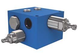
7 POCLIN HYDRULICS Power transmission - nti slipping valves NTI-SLIPPING/SMRTDRIVE VLVE VM H15 nti-slipping Electronically managed Programmable Operation The anti-slipping valve is an electronically managed traction control, which operates to restrict flow only when slippage is detected, by using normally wheel speed sensors and open proportional valves. Entirely programmable, the system easily accommodates varying motor displacements and vehicle steering geometry to offer optimal performance. Features Hydraulic symbol E1 E2 F P G Pr Pr M1 M2 nti-slipping/smartdrive valve VM H15 Hydraulic Max. pressure bar [PSI] 450 [6 526] Nominal flow range L/min [GPM] up to 240 [63.4] Max restricted flow L/min [GPM] 50 [3.44] Type of hydraulic connections Mass piped version flanged version Surface treatment ISO 6162 (ride SE) / ISO (Metric) / ISO (UNF SE) kg [lb] 7,2 [15.9] 11,9 [26.2] Phosphated Fluid temperature C [ F] -20 to +70 [- 4 to +158] Fluid viscosity mm 2 /s [ssu] 15 to 380 [69.5 to 1 760] Fluid contamination ISO /16/13 Electrical Solenoid supply voltage V direct Solenoid current M Type of control m PWM 100 Hz recommended Pressure drop [bar] [PSI] nti-slipping/twinlock valve VDP H Q [L/min] [GPM] The valves must be supplied in G with a pressure between bar [ PSI]. Maximum flow, from P to or, for a fully open valve, is 120 L/min [31.7 GPM] per wheel with a pressure diference (P) of 5 bar [72 PSI]. (96 cst mineral oil at 25 C [77 F]. 13/03/2018 7
8 nti slipping valves - Power transmission POCLIN HYDRULICS Dimension for piped version V M - H [1.10] 20 [0.79] 16 [0.63] 55 [2.17] 81 [3.19] 39 [1.54] +0,2 50-0, [ ] 256 [10.08] Serial number 16 [0.63] 100 [3.94] 92 [3.62] 124 [4.88] 132 [5.19] 16 [0.63] 64 [2.52] 89,5 [3.52] 118 [4.65] 2xM10x2 Installation Mounting position: Indifferent Class (*) N.m [lb.ft] 2xM [36] (*) s per standard DIN 912 Motor and valve drain piping must be connected directly to the tank. Hydraulic connections Option 1 Option Max. pressure Port Function Connections Standards Connections Standards bar [PSI] N.M. P HP function DN 25 PN400 ISO 6162 DN 25 PN400 ISO [6 526] 90 - HP function M27x2 ISO /16-11 UNF-2 ISO [6 526] 200 F Drain M14x1,5 ISO /16-18 UNF-2 ISO [14.5] 45 G LP supply M14x1,5 ISO /16-18 UNF-2 ISO <P<30 45 M1-M2 Pressure measurement M14x1,5 ISO M14x1,5 ISO <P< /03/2018
9 POCLIN HYDRULICS Power transmission - nti slipping valves Dimension for flanged version V M - H E1,E2 16 [0.62] E1 E2 4xM12 M1 G P F 9 [0.35] 33 [1.29] 44 [1.73] 20,5 [0.80] 4 [0.16] 37 [1.46] 37 [1.46] +0, ,3 [4.96 ] [5.91] 16 [0.62] 4 [0.16] M12 z=4 Ø6 [0.24 dia.] 66 [2.59] 62 [2.44] YYY nti-slipping/smartdrive valve VM H15 55 [2.17] 81,5 [3.21] 97,5 [3.84] 96,5 [3.79] 256 [10.07] Installation Remove the protection plate. Make sure that Q-rings are correctly positioned. Install the valve on the mounting face with the help from the lug. Mounting position: Indifferent Hydraulic connections Option 4 Option Max. pressure Port Function Connections Standards Connections Standards bar [PSI] N.M. P HP function flanged Ø25 [dia. 0.98] 450 [6 526] - HP function flanged Ø16 [dia. 0.63] 450 [6 526] F Drain M14x1,5 ISO /16-18 UNF-2 ISO [14.5] 45 G LP supply M14x1,5 ISO /16-18 UNF-2 ISO <P<30 45 M1-M2 Pressure measurement 150 min. [5.90 min.] 24±0,2 [0.94±0.01] Z 126±0,2 [4.96±0.01] 4x M12 Ø25 max. [max dia.] 63±0,2 [2.48±0.01] Class (*) N.m [lb.ft] 4xM [63.5] 73 min. [2.87 min.] 44±0,2 [1.73±0.01] Motor and valve drain piping must be connected directly to the tank. C C P 9±0,2 [0.35±0.01] Ø16 max. [max dia.] Lug Ø6±0.2[0.24±0.01] Height 4 [0.16] Ø16 max. [max dia.] 11 [0.43] M14x1,5 ISO M14x1,5 ISO <P< ±0,2 [1.45±0.01] 37±0,2 [1.45±0.01] Ra 1,5 Ra 12,5 (*) s per standard DIN 912 0,03 [0.01] 0,1 [0.04] X Z C-C min. 18 [min. 0.70] X nti-slipping/twinlock valve VDP H10 13/03/2018 9
10 nti slipping valves - Power transmission POCLIN HYDRULICS Model code V M - H Type Valve Multifunctional nti-slipping V M Operating pressure High pressure bar [6 961 PSI] Input / Flow up to 240 L/min [63.4 GPM] 15 H Options 0 Without Fluorinated elastomer seals 1 compatible with C and D fluids Zinc-chromated C Primer paint D Special paint or no paint Name plate specific to the P customer F Customized * * Further description on interface drawing Controled flow 20 L/min [5.3 GPM] L/min [13.0 GPM] 050 High pressure setting Without Setting: value by 3-figure number Connectors 0 Without 3 Deutsch DT04-2P 5 MP Junior Timer (6,3 x 0,8) Technology With low pressure protection 1 With low/high pressure protection 2 Fixation type lock (to pipping) 1 Flange PH * 6 * Flange for mounting Hydraulic connections 0 Without ISO 6162 (ride SE) 1 & ISO (Metric) * 4 ISO (Metric) ** ISO (UNF SE) * Only for piped version **Only for flanged version Control type 1 12V DC 2 24 V DC 10 13/03/2018

![Hydraulic symbol 2 positions 3 positions nti-slipping/smartdrive valve VM H15 Features 2 positions 3 positions Max. pressure bar [PSI] 450 [6 526] Nominal flow range L/min [GPM] 26 to 50 [6.8 to 13.](/docs-images/82/85731598/images/11-2.jpg "2] Max. restricted flow bar [PSI] 50 [725] Type of hydraulic connection ISO 1179-1 Mass kg [lbs] 2,65 [5.84] 3,33 [12.")
11 POCLIN HYDRULICS Power transmission - nti slipping valves NTI-SLIPPING/TWINLOCK VLVE VDP H10 nti-slipping utomatic transfer of torque to the wheels Maximize wheel ground adhesion Operation VDP anti-slipping valve provides flow division while automatically transferring torque to the wheels with the greatest ground adhesion. Hydraulic symbol 2 positions 3 positions nti-slipping/smartdrive valve VM H15 Features 2 positions 3 positions Max. pressure bar [PSI] 450 [6 526] Nominal flow range L/min [GPM] 26 to 50 [6.8 to 13.2] Max. restricted flow bar [PSI] 50 [725] Type of hydraulic connection ISO Mass kg [lbs] 2,65 [5.84] 3,33 [12.8] Surface treatment Zn plating 12/C (EN ) Fluid temperature C [ F] -20 to +70 [-4 to +158] Fluid viscosity mm2/s [SSU] 15 to 380 [69.5 to 1 760] Type of hydraulic connections ISO (SPP) nti-slipping/twinlock valve VDP H10 13/03/


 V D P - H 1 0-3 - -")
12 nti slipping valves - Power transmission POCLIN HYDRULICS Dimensions for 2 positions V D P - H Dimensions for 3 positions command type short V D P - H Dimensions for 3 positions command type long (according to model code) V D P - H /03/2018
13 POCLIN HYDRULICS Power transmission - nti slipping valves Installation Mounting position: Indifferent 1 Class (*) N.m [lb.ft] 2xM [18] (*) s per standard DIN 912 Hydraulic connections Port Function Connections Max. pressure bar [PSI] Nm [lb.ft] ±10 % (as per standard DIN 912) P-- HP function M18x1,5 450 [6 526] 70 [52] X Pilot 50 [752] M14x1,5 L Drain 3 [45] 45 [33] Mechanical control The operation of the cam on the roller must be limited ±30 to limit the parasite forces. eginning of opening N [lbf] End of opening N [lbf] Max. stroke mm [in] 2 positions 25 [5.62] 55 [12.36] 10 [0.39] 3 positions 49 [11.02] 170 [38.22] 16 [0.6] nti-slipping/smartdrive valve VM H15 Hydraulic control eginning of opening bar [PSI] End of opening bar [PSI] 2 positions 5 [72.5] 11 [160] 3 positions 4 [58] 15 [218] Max. pressure bar [PSI] 50 [725] 2 positions 3 positions mm² in² mm² in² mm in bar PSI mm in bar PSI nti-slipping/twinlock valve VDP H10 13/03/
14 nti slipping valves - Power transmission POCLIN HYDRULICS Model code V D P - H Type Valve Directional Progressive Operating pressure High pressure 450 bar [6 526 PSI] Debit / Flow 26 to 50 L/min [7.0 to 13.0 GPM] V D P H 10 Number of ways 3 ways 3 Number of positions 2 positions 2 3 positions 3 Progressiveness Without 0 Type 1 * 1 Type 2 * 2 Type 3 ** 3 * vailable only with 3 positions ** vailable only with 2 positions G Fixation type 1 lock (to piping) 0 Reserved Use 0 Standard 1 With function road Command type 0 Without 1 Short 2 Long Connector 0 Without Hydraulic connections 3 ISO (SPP) Control type Mechanical-roller Technology Monobloc M Options 0 Without Fluorinated elastomer seals compatible 1 with C and D fluids Phosphate treated Zinc-chromated C Primer paint D Special paint or no paint P Name plate specific to the customer F Customized * * Further description on interface drawing 14 13/03/2018


15 CONTENT POCLIN HYDRULICS Power transmission - Exchange valves EXCHNGE VLVES Exchange valve VE10 17 Exchange valve VE10 Exchange valve VE30 21 Exchange valve VE30 High performance Exchange valve VE60 25 High performance Exchange valve VE60 Exchange and High pressure relief valve VES60 31 Exchange and High pressure relief valve VES60 13/03/18 15
16 Exchange valves - Power transmission POCLIN HYDRULICS 16 13/03/18
17 POCLIN HYDRULICS Power transmission - Exchange valves EXCHNGE VLVE VE10 Compact Heavy duty Exchange valve VE10 Operation Exchange valves are for use in bleeding hot oil from the low pressure side of a hydrostatic transmission circuit. The hot oil can be cooled, filtered or used as a source of oil for flushing other pump and motor case. Features Hydraulic symbol Max. pressure bar [PSI] 450 [6 526] Exchange relief valve setting bar [PSI] 14; 16; 18; 20 [203; 232; 261; 290] Selector spool switching pressure bar [PSI] 8,5 [123] Exchange flow (11 bar [160 PSI] P) L/min [GPM] max.15 [3.96] ( P T or T) Exchange direction Forward and/or reverse Type of hydraulic connections ISO (SPP) / ISO (Metric) / ISO (UNF SE) Mass kg [lbs] 1,1 [2.43] Operation Example: relief valve set at 20 bar [290 PSI] P [bar] Exchange valve VE30 High performance Exchange valve VE60 Pressure drop Q [L/min] Exchange and High pressure relief valve VES60 13/03/18 17
18 Exchange valves - Power transmission POCLIN HYDRULICS Dimensions T Hydraulic connections Port Function ISO (Metric) Type N Connections ISO (SPP) Type N ISO (UNF SE) Max. pressure bar [PSI] HP/LP connection 450 [6 526] HP/LP connection M18 x 1.5 G 3/8 SPP 9/16-18 UNF-SE T Tank connection 5 [72.5] 18 13/03/18
19 POCLIN HYDRULICS Power transmission - Exchange valves Model code Type Valve Exchange Nominal flow 10 L/min [2.64 GPM] 10 Exchange direction Unidirectional ( T) idirectional V E V E C Exchange opening pressure 14 bar [203 PSI] bar [232 PSI] bar [261 PSI] bar [290 PSI] 20 Relief valve Not adjustable 0 Restrictor diameter 00 Without restrictor 10 1,0 mm [0.039 in] 12 1,2 mm [0.047 in] 14 1,4 mm [0.055 in] 16 1,6 mm [0.063 in] 18 1,8 mm [0.071 in] Options 0 Without Zinc-chromated D Special paint or no paint Name plate specific to the P customer F Customized * * Further description on interface drawing Hydraulic connections 3 ISO (SPP) 4 ISO (Metric) ISO (UNF SE) ssembly version 1 Piped block Mechanic setting range Without Pressure gauge port 0 Without Exchange valve VE10 Exchange valve VE30 High performance Exchange valve VE60 Exchange and High pressure relief valve VES60 13/03/18 19
20 Exchange valves - Power transmission POCLIN HYDRULICS 20 13/03/18
21 POCLIN HYDRULICS Power transmission - Exchange valves EXCHNGE VLVE VE30 Compact djustable Heavy duty Piped valve Flanged valve Exchange valve VE10 Features Hydraulic symbol Exchange valves are for use in bleeding hot oil from the low pressure side of a hydrostatic transmission circuit. The hot oil can be cooled, filtered or used as a source of oil for flushing other pump and motor case. Features Max. pressure bar [PSI] 500 [7 252] Exchange relief valve setting bar [PSI] 10 to 30 [145 to 435] Selector spool switching pressure bar [PSI] 8 [116] Exchange flow (10 bar [145 PSI] P) L/min [GPM] 30 [7.93] ( P T or T) Exchange direction Forward and/or reverse Type of hydraulic connections ISO (SPP) / ISO (Metric) / ISO (UNF SE) Mass kg [lbs] 1,5 [3.31] Pressure drop Example: relief valve set at 20 bar [290 PSI] Pressure drop P [bar] Q [L/min] P [bar] P-Q Performance curves djustable area Q [L/min], to T - 30 bar [435 PSI], to T - 10 bar [145 PSI] Exchange valve VE30 High performance Exchange valve VE60 Exchange and High pressure relief valve VES60 13/03/
![Exchange valves - Power transmission POCLIN HYDRULICS Dimensions for piped valve Metric connections V E 3 0 - - - 1 - UNF connections 40 [1.57] 16 [0.63] 54 [2.12] 16 [0.](/docs-images/82/85731598/images/22-0.jpg "63] S=4 S=13; Md=24+2 Nm 145,5 max. [max. 5.73] 122,5 [4.82] 2x Ø5,6 [2 x dia.0.22] T 60 [2.36] 5 [0.20] 5 [0.20] 22 [0.87] 56 [2.20] 77 [3.03] M 70 [2.75] 18 [0.71] 11,5 [0.45] 35 [1.")
22 Exchange valves - Power transmission POCLIN HYDRULICS Dimensions for piped valve Metric connections V E UNF connections 40 [1.57] 16 [0.63] 54 [2.12] 16 [0.63] S=4 S=13; Md=24+2 Nm 145,5 max. [max. 5.73] 122,5 [4.82] 2x Ø5,6 [2 x dia.0.22] T 60 [2.36] 5 [0.20] 5 [0.20] 22 [0.87] 56 [2.20] 77 [3.03] M 70 [2.75] 18 [0.71] 11,5 [0.45] 35 [1.38] 22 13/03/2018
23 POCLIN HYDRULICS Power transmission - Exchange valves Hydraulic connections Port Function HP/LP connection ISO (Metric) Type N Connection ISO (SPP) Type N ISO (UNF SE) Max. pressure bar [PSI] HP/LP connection 500 [7 252] pressure measurement M18 x 1.5 G3/8 SPP 3/4-16 UNF-SE M or service connection T Tank connection 5 [72.5] Exchange valve VE10 Dimensions for flanged valve V E ,5 max. [max. 5.69] 121,5 [4.78] 4x Ø6,6 [4 x dia.0.26] 56±0,2 [2.20±0.008] 70 [2.75] 93 [3.66] s=13; Md=24+2 Nm 7 [0.27] 62±0,2 [2.44±0.008] 7 [0.27] 76 [2.99] 11,5 [0.45] s=4 35 [1.38] 37±0,1 [1.45±0.004] 9,7±0,1 [0.38±0.004] 14±0,01 [0.55±0.0004] 28±0,1 [1.10±0.004] 42±0,1 [1.65±0.004] T Exchange valve VE30 High performance Exchange valve VE60 Hydraulic connections Port Function Connection HP/LP connection Ø 7 mm HP/LP connection [dia in] T Tank connection Ø 9 mm [dia in] Max. pressure bar [PSI] 500 [7 252] 5 [72.5] Exchange and High pressure relief valve VES60 13/03/
24 Exchange valves - Power transmission POCLIN HYDRULICS Model code V E Type Valve Exchange V E Max. flow 30 L/min [7.93 GPM] 30 Exchange direction Unidirectional ( T) Unidirectional ( T) idirectional C Exchange opening pressure 10 bar [145 PSI] bar [174 PSI] bar [203 PSI] bar [232 PSI] bar [261 PSI] bar [290 PSI] bar [319 PSI] bar [348 PSI] bar [377 PSI] bar [406 PSI] bar [435 PSI] 30 M port 0 Without M With * Hydraulic connections 3 ISO (SPP) 4 ISO (Metric) ISO (UNF SE) ssembly version 1 Piped valve 6 Flanged valve (,, T) Specific options 0 Without Zinc-chromated D Special paint or no paint Name plate specific to the P customer F Customized * * Further description on interface drawing * Only for piped valve Type of exchange Relief valve not adjustable 0 djustable relief valve Mechanic setting range Low range: 10 to 20 bar [145 to 290 PSI] High range: 20 to 30 bar [290 to 435 PSI] Restrictor diameter Without /03/2018
25 POCLIN HYDRULICS Power transmission - Exchange valves HIGH PERFORMNCE EXCHNGE VLVE VE60 Compact djustable Heavy duty Flanged version Piped version Exchange valve VE10 Operation Hydraulic symbol Exchange valves are for use in bleeding hot oil from the low pressure side of a hydrostatic transmission circuit. The hot oil can be cooled, filtered or used as a source of oil for flushing other pump and motor case. Features Flanged version Piped version Max. pressure bar [PSI] 500 [7 252] Exchange relief valve setting bar [PSI] 12 to 30 [174 to 435] Selector spool switching pressure bar [PSI] 8 [116] Exchange flow (10 bar [145 PSI] P) L/min [GPM] 60 [15.9] Exchange direction Forward and/or reverse Type of hydraulic connections ISO (SPP) / ISO (Metric) / ISO (UNF SE) Mass kg [lbs] 2,4 [5.29] 3,2 [7.05] Pressure drop Example: relief valve set at 20 bar [290 PSI] Pressure drop P-Q Performance curves P [bar] djustable area Q [L/min] Q [L/min] P [bar], to T - 30 bar [435 PSI], to T - 12 bar [173 PSI] Exchange valve VE30 High performance Exchange valve VE60 Exchange and High pressure relief valve VES60 13/03/18 25
26 Exchange valves - Power transmission POCLIN HYDRULICS Dimensions for piped version V E ,5 [2.62] 61,5 [2.42] 57 [2.24] 25,5 [1.00] S=4 S=13, Ma=24+2 Nm 91,5 [3.60] 67,5 [2.66] 23,5 [0.93] 7 [0.28] 25,5 [1.00] 124 [4.88] M 55 [2.17] 86±0,2 [3.39] 98 [3.86] M 34,5 [1.00] M 75,5 [2.97] M 27,5 [1.08] 114 [4.49] 27 [1.06] 172 [6.77] 25,5 [1.00] 15,5 [0.61] - 2x Ø13,5 [0.53 dia.] 2x Ø8,5 [0.33 dia.] 66,5 [2.62] Hydraulic connections Port Function ISO Type N Connection ISO Type N ISO Max. pressure bar [PSI] HP/LP connection 500 [7 251] HP/LP connection M22x1.5 G1/2 SPP 7/8-14 UNF-SE T Tank connection 5 [72.5] M Pressure measurement () M14x1.5 G1/4 SPP 9/16-18 UNF-SE 500 [7 251] M Pressure measurement () M Pressure measurement or service connection M22x1.5 G1/2 SPP 7/8-14 UNF-SE 500 [7 251] 26 13/03/18
27 POCLIN HYDRULICS Power transmission - Exchange valves Dimensions for flanged version 124 [4.88] 73,4 [2.89] 24 [0.94] 9 [0.35] 32,7 [1.29] 15 [0.59] V E [1.34] M M 4x Ø8,5 [dia. 0.33] 175 [6.89] 114 [4.49] 27 max. [1.06] S=4 S=13, Ma=24+2 Nm 26,5 [1.04] 50,5 [1.99] 54 [2.13] Exchange valve VE10 Exchange valve VE30 85,5 [3.37] 4x Ø13,5 [dia. 0.53] 72,8 [2.87] 53 [2.09] 33,2 [1.31] T 2,3 ± 0,1 [0.09 ± 0.004] 65 ± 0,2 [2.56 ± 0.008] Mating surface quality c 0,01 Rmax 4 High performance Exchange valve VE60 Hydraulic connections Port 24,2 [0.95] 48,4 ± 0,2 [1.91 ± 0.008] Function ISO Type N Connection ISO Type N ISO Max. pressure bar [PSI] HP/LP connection Ø14 mm [dia in] Ø14 mm [dia in] Ø14 mm [dia in] 500 [7 251] HP/LP connection T Tank connection Ø10 mm [dia in] Ø10 mm [dia in] Ø10 mm [dia in] 5 [72.5] M Pressure measurement () M14x1.5 G1/4 SPP 9/16-18 UNF [7 251] M Pressure measurement () Exchange and High pressure relief valve VES60 13/03/18 27
28 Exchange valves - Power transmission POCLIN HYDRULICS Dimensions with T port piped - optional V E T - S=13, Ma=24+2 Nm S=4 4x Ø8,5 [0.34] THRU Ø13,5 23 7,8 [0.31] M 106 [4.17] 68 [2.68] 38 [1.49] M 12,7 [0.49] 52,3 [2.06] 20,5 [0.81] 65±0,2 [2.57±0.008] 9 [0.35] 106 [4.17] 80 [3.15] 178 [7.01] 43,5 [1.71] 25 [0.98] 25 [0.98] 45 [1.77] 2,3±0,1 [0.09±0.004] 22,2 [0.87] 48,4±0,2 [1.91±0.008] 25 [0.98] T Hydraulic connections Port Function ISO (Metric) Type N HP/LP connection Ø14 mm HP/LP connection [dia in] Connection ISO (SPP) Type N Ø14 mm [dia in] ISO (UNF SE) Ø14 mm [dia in] Max. pressure bar [PSI] 500 [7 251] T Tank connection M22x1.5 G1/2 SPP 7/8-14 UNF-2 5 [72.5] M Pressure measurement () M14x1.5 G1/4 SPP 9/16-18 UNF [7 251] M Pressure measurement () 28 13/03/18
29 POCLIN HYDRULICS Power transmission - Exchange valves Model code Type Valve Exchange V E V E Exchange valve VE10 Max. flow 60 L/min [15.85 GPM] 60 Exchange direction Unidirectional ( T) Unidirectional ( T) idirectional C Exchange opening pressure 12 bar [174 PSI] bar [203 PSI] bar [232 PSI] bar [261 PSI] bar [290 PSI] bar [319 PSI] bar [348 PSI] bar [377 PSI] bar [406 PSI] bar [435 PSI] 30 Type of exchange Relief valve not adjustable 0 djustable relief valve Restrictor diameter Without 0 M port 0 Plugged/Without * M Open ** * M port plugged only with piped version ** Only available with piped valve ssembly version 2 Piped block - casted body 7 Flanged block (,, T) - casted body T Flanged valve with T port piped Mechanic setting range Low range: 12 to 18 bar [174 to 261 PSI] High range: 18 to 30 bar [261 to 435 PSI] Options 0 Without 1 With by-pass (-, -) D Special paint or no paint Zinc-chromated Name plate specific to the P customer F Customized * * Further description on interface drawing Hydraulic connections 3 ISO (SPP) 4 ISO (Metric) ISO (UNF SE) Exchange valve VE30 High performance Exchange valve VE60 Exchange and High pressure relief valve VES60 13/03/18 29
30 Exchange valves - Power transmission POCLIN HYDRULICS 30 13/03/18

31 POCLIN HYDRULICS Power transmission - Exchange valves EXCHNGE ND HIGH PRESSURE RELIEF VLVE VES60 Compact djustable Heavy duty Integrated High pressure relief valve Exchange valve VE10 Operation Exchange valves are for use in bleeding hot oil from the low pressure side of a hydrostatic transmission circuit. The hot oil can be cooled, filtered or used as a source of oil for flushing other pump and motor case. Hydraulic symbol T M Features Max. pressure bar [PSI] 450 [6 526] Exchange relief valve setting bar [PSI] 12 to 30 [174 to 435] Selector spool switching pressure bar [PSI] 8 [116] Exchange flow (10 bar [145 PSI] P) L/min [GPM] 60 [15.9] Exchange direction Forward and/or reverse Type of hydraulic connections ISO (SPP) / ISO (Metric) / ISO (UNF SE) Mass kg [lbs] 7,3 [16.09] Pressure drop Example: relief valve set at 20 bar [290 PSI] Pressure drop P-Q Performance curves P [bar] djustable area Q [L/min] Q [L/min] P [bar] M, to T - 30 bar [435 PSI], to T - 12 bar [173 PSI] M Exchange valve VE30 High performance Exchange valve VE60 Exchange and High pressure relief valve VES60 13/03/18 31
32 Exchange valves - Power transmission POCLIN HYDRULICS Dimensions for VES60 flanged version 80 [3.15] 39,5 [1.56] 52,5 [2.07] S=13, Ma=24+2 Nm S=4 115 [4.53] max. 187 [max. 7.36] 43,5 [1.71] 27,5±0,2 [1.08±0.008] 25 [0.98] 106 [4.17] 124 [4.88] max. 226 [8.89] T 73,4 [2.89] M M M T 43 [1.69] 66,5 [2.62] 60 [2.36] 82,5 [3.25] 76±0,2 [2.99±0.008] 66±0,2 [2.59±0.008] 59,5 [2.36] 32,7 [1.29] 62 [2.44] 5 [0.19] 17 [0.67] 20 [0.79] 0 0 V E S ,5 [0.18] +0,3 52, [2.08 ] 33±0,2 [1.29±0.008] +0,3 13, [0.52 ] 4x Ø8,5 [dia. 0.33] 80,5±0,2 [3.17±0.008] 32 13/03/18
33 POCLIN HYDRULICS Power transmission - Exchange valves Dimensions for VES60 piped version V E S [3.15] 57 [2.24] 28 [1.10] 21 [0.83] 4 [0.16] T S=4 S=13, Ma=24+2 Nm Exchange valve VE10 30 [1.18] 55 [2.17] 57 [2.24] 226 [8.90] 124 [4.89] 106 [4.17] 73,3 [2.89] 32,6 [1.28] 45 [1.77] M M 2x Ø8,5 [dia. 0.33] 90±0,2 [3.54±0.008] 76 [2.99] M 21 [0.83] 53 [2.09] 53 [2.09] Exchange valve VE30 8 [0.31] 30 [1.18] 57 [2.24] 70 [2.76] 80 [3.15] 115 [4.53] 30 [1.18] 43,5 [1.71] max. 25 [max. 1.06] High performance Exchange valve VE60 Hydraulic connections Port Function ISO (SPP) Connection ISO (Metric) ISO (UNF SE) Max. pressure bar [PSI] HP/LP connection G3/4 M27x2 1 1/16-12 UNF [6 526] HP/LP connection T Tank connection G1/2 M22x1.5 7/8-14 UNF-2 5 [72.5] M Pressure measurement () G1/4 M14x1.5 9/16-18 UNF [6 526] M Pressure measurement () M Pressure measurement of service connection max. 188 [max. 7.40] G1/2 M22x1.5 7/8-14 UNF [6 526] Exchange and High pressure relief valve VES60 13/03/18 33
34 Exchange valves - Power transmission POCLIN HYDRULICS Model code V E S Type Valve Exchange Safety V E S Max. flow 60 L/min [15.85 GPM] 60 Options 0 Without D Special paint or no paint Primer paint Exchange direction Unidirectional ( T) Unidirectional ( T) idirectional C Exchange opening pressure 12 bar [174 PSI] bar [203 PSI] bar [232 PSI] bar [261 PSI] bar [290 PSI] bar [319 PSI] bar [348 PSI] bar [377 PSI] bar [406 PSI] bar [435 PSI] 30 Spring range: Low range = bar Spring range: High range = bar M port 0 Without M With * * M thread size =,, T) Hydraulic connections 3 ISO (SPP) 4 ISO (Metric) ISO (UNF SE) ssembly version 1 Piped block 6 Flanged block Exchange relief setting Not adjustable 0 djustable High pressure relief valve type -; - (djustable) 3 High pressure relief valve setting on bar [2 320 PSI] bar [3 045 PSI] bar [3 625 PSI] bar [4 351 PSI] bar [5 076 PSI] bar [6 091 PSI] High pressure relief valve setting on 160 bar [2 320 PSI] bar [3 045 PSI] bar [3 625 PSI] bar [4 351 PSI] bar [5 076 PSI] bar [6 091 PSI] /03/18
35 CONTENT POCLIN HYDRULICS Power transmission - Freewheeling valves FREEWHEELING VLVES Freewheeling valve VDF H15 37 Freewheeling valve VDF H15 Freewheeling valve VDF H25 41 Freewheeling valve VDF H25 13/03/18 35
36 Freewheeling valves - Power transmission POCLIN HYDRULICS 36 13/03/18

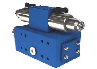
37 POCLIN HYDRULICS Power transmission - Freewheeling valve FREEWHEELING VLVE VDF H15 Free-wheeling Heavy duty Reliable Operation The free-wheeling valve allows to disengage the hydraulic motor by allowing the pistons to return in cylinder-blocks and the motor to turn in freewheeling mode. It prevents contacts of camring and pistons at high speed. Features Hydraulic symbol F G PR PV G2 R V Freewheeling valve VDF H15 Hydraulic Max. pressure bar [PSI] 450 [6 526] Nominal flow range L/min [GPM] 50 to 95 [13.20 to 25] Min. control pressure bar [PSI] 10 [145] Type of hydraulic connections ISO (SPP) / ISO (Metric) / ISO (UNF SE) Mass without pilot valve with pilot valve: 2 positions with pilot valve: 3 positions kg [lb] 11,8 [26.01] 18,3 [40.34] 19,1 [42.10] Surface treatment Zn plating Fe/Zn8/Cn/T2 (DIN 50979) Fluid temperature C [ F] -20 to +90 [-4 to -200] Fluid viscosity mm 2 /s [ssu] 15 to 380 [69.5 to 1 760] Fluid contamination ISO /16/13 Electrical Solenoid supply voltage V direct 12/24V V alternative 110V Solenoid duty cycle Continuous Max. ambient temperature C [ F] 50 [122] Pressure drop Measured at 20 C [68 F] [bar] 5 4,5 4 3,5 3 2,5 2 1,5 1 0,5 0 [PSI] Freewheeling valve VDF H Q [L/min] [GPM] 13/03/18 37
38 Freewheeling valve - Power transmission POCLIN HYDRULICS Dimensions without pilot valve V D F - H x M10 64 [2.52] 32 [1.26] 47 [1.85] min. 17 [0.67] min. 24 [0.94] 16 [0.63] 157 [6.18] 4 [0.16] 189 [7.44] 143,5 [5.65] 39 [1.54] 106 [4.17] 47 [1.85] 18 [0.71] 26 [1.02] 45,5 [1.79] PV 94,5 [3.72] [0.94] F G PR 94 [3.70] 43,1 [1.69] 94 [3.70] 96±0,2 [3.78±0.01] R V 46,5 [1.83] 5±0,2 [0.19 ±0.01] 10 [0.39] 30±0,2 [1.18 ±0.01] 24 [0.94] 70,5 [2.77] 70,5 [2.77] C - 4x M12 95,5 [3.76] 37,3 [1.47] 27 [1.06] 16,7 [0.66] 3,2 [0.12] 5x Ø11 C-C 4x M6 min. 18 [0.71] min. 23 [0.91] min. 12 [0.47] min. 15 [0.59] 46±0,2 [1.81±0.01] 32,5 [1.28] 21,4 [0.84] 7,4 [0.29] 6,3 [0.24] C 50,8 [1.99] 54±0,2 [2.12 ±0.01] G F PR PV G2 R V 38 13/03/18
39 POCLIN HYDRULICS Power transmission - Freewheeling valve Dimensions with pilot valve (two positions) V D F - H [0.16] 54 [2.13] 8 [0.31] 268 [10.55] 70 [2.76] 38 [1.49] 118,5 [4.67] 70,5 [2.78] 94 [3.70] 24 [0.94] 45,5 [1.79] 02 G PV F 94,5 [3.72] 106 [4.17] 143,5 [5.65] 189 [7.44] PR 23 [0.91] 47 [1.85] 73 [2.99] 39 [1.54] 135 [5.31] 205,5 [8.09] 178 [7.00] 94 [5.31] 47 [1.85] 94 [3.70] 37 [1.46] Thread depth: 4x M12 min. 18 [min. 0.71] F G R 96 [3.78] V 46,5 [1.83] 30 [1.18] 22 [0.87] Freewheeling valve VDF H15 PR PV G2 R V Dimensions with pilot valve (three positions) V D F - H ,2 [2.65] 347 [13.67] 70 [2.76] 38 [1.49] 96±0,2 [3.78±0.01] 76 [2.99] 24 [0.94] 45,5 [3.72] 02 G PV F 94,5 [3.72] 106 [4.17] 143,5 [5.65] 189 [7.44] 228 [8.98] PR 23 [0.91] 47 [1.85] 39 [1.54] 73 [2.87] 135,5 [5.33] 190 [7.48] 177 [6.97] 94 [3.70] 47 [1.85] 94 [3.70] 98 [3.86] 37 [1.46] 4x M12 17/23 F G R V 118,5 [4.67] 30 [1.18] 22 [1.18] 46,5 [1.83] 70,5 [2.78] Freewheeling valve VDF H25 278,8 [10.98] PR PV G2 R V 13/03/18 39
40 Freewheeling valve - Power transmission POCLIN HYDRULICS Hydraulic connections Port PV-PR Function Input forward - Input reverse forward ISO (SPP) Connections ISO (Metric) ISO (UNF SE) Max. pressure bar [PSI] G27 (G3/4) M27x2 1 1/16-12 UNF [6 526] Min. pressure bar [PSI] V-R Output forward - Output reverse forward G27 (G3/4) M27x2 1 1/16-12 UNF [6 526] F Drain G27 (G3/4) M27x2 1 1/16-12 UNF-2 50 [725] G Pilot G27 (G3/4) M27x2 1 1/16-12 UNF-2 50 [725] 10 [145] G2 Pilot G13 (G1/4) M14x1,5 9/16-18 UNF-2 50 [725] Installation Model code Mounting position: Indifferent Class (*) N.m [lb.ft] 4xM [36] (*) s per standard DIN 912 C D E F G 1 2 V D F H Type Valve Direction Free-Wheel V D F Operating pressure High pressure bar [6 526 PSI] Flow 50 to 95 L/min [13 to 25 GPM] 15 y-pass pump Without 0 With 1 H Pilot valve Without 0 With 1 Options 0 Without (spool type 14) 2 Spool type 2 9 Spool type 9 Zinc-chromated D Special paint or no paint F Customized * * Further description on interface drawing Drain/Pilot connections 0 Without 3 ISO (SPP) 4 ISO (Metric) ISO (UNF SE) Pump/Motor connections 0 Without 3 ISO (SPP) 4 ISO (Metric) ISO (UNF SE) Working ports When C1=0 0 4 channels 4 3 channels 3 Number of positions When C1=0 0 2 positions 2 3 positions 3 Voltage Without 0 12 V 1 24 V V 3 Connector type 0 Without (connector w/o plug) * 1 Naked wires 2 Packard 3 Deutsch DT04-2P 4 Hirschmann DIN MP Junior Timer (6,3 x 0,8) * Plug to be ordered separately Current type 0 Without D DC C 40 13/03/18

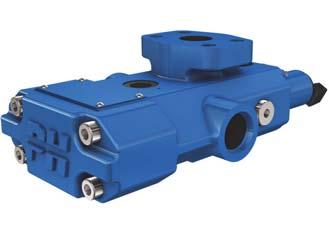
41 POCLIN HYDRULICS Power transmission - Freewheeling valve FREEWHEELING VLVE VDF H25 Free-wheeling Heavy duty Reliable Operation The free-wheeling valve allows to disengage the hydraulic motor by allowing the pistons to return in cylinder-blocks and the motor to turn in freewheeling mode. It prevents contacts of camring and pistons at high speed. Hydraulic symbol F G PR PV G2 R V Freewheeling valve VDF H15 Features Hydraulic Max. pressure bar [PSI] 450 [6 526] Nominal flow range L/min [GPM] 170 to 300 [44.90 to 79.25] Min. control pressure bar [PSI] 10 [145] Type of hydraulic connections ISO (SPP); ISO (Metric) / ISO (UNF SE) / ISO 6162 (ride SE) Mass without pilot valve with pilot valve: 2 positions with pilot valve: 3 positions kg [lb] 32 [70.55] 38,5 [84.88] 39,3 [86.64] Surface treatment Zn plating Fe/Zn8/Cn/T2 (DIN 50979) Fluid temperature C [ F] -20 to +90 [-4 to -200] Fluid viscosity mm 2 /s [ssu] 15 to 380 [69.5 to 1 760] Fluid contamination ISO /16/13 Electrical Solenoid supply voltage V direct 12/24V V alternative 110V Solenoid duty cycle Continuous Max. ambient temperature C [ F] 70 [158] Pressure drop Measured at 20 C [68 F] [bar] 2,5 2 [PSI] Freewheeling valve VDF H25 1, , Q [L/min] [GPM] 13/03/18 41
42 Freewheeling valve - Power transmission POCLIN HYDRULICS Dimensions without pilot valve V D F - H [1.97] 30 [1.18] G 100 [3.94] R V 53 [2.09] 113 [4.45] 173 [6.81] 55 [2.17] Ø55 [dia. 2.17] 90 [3.54] 140 [5.51] 100 [3.94] 90 [3.54] 70 [2.76] 50 [1.97] 45 [1.77] min. 19 [0.75] max. 24 [0.94] - 4Ø x M10 50 [1.98] 228 [8.97] 25 [0.98] 328 [12.91] 82 [3.23] 60 [2.36] 50 [1.97] PR PV F 41,5 [1.63] 184,5 [7.26] 22 [0.87] G F PR PV G2 R V 42 13/03/18
43 100 [3.94] 50 [1.96] 50 [1.96] 83 [3.27] 25 [0.98] POCLIN HYDRULICS Power transmission - Freewheeling valve Dimensions with pilot valve (two positions) V D F - H ,2 [11.31] 111,5 [4.39] 70 [2.75] 37 [1.46] 107,7 [4.24] 15 [0.59] 30 [1.18] V 120 [4.72] 328 [12.91] F R G2 113 [4.44] 53 [2.08] 193,4 [7.61] 90 [3.54] 140 [5.51] 25 [0.98] PR 41,5 [1.63] G 143 [5.62] PV Freewheeling valve VDF H15 F G PR PV G2 R V Dimensions with pilot valve (three positions) V D F - H [0.59] 30 [1.18] V 347 [13.66] 111,5 [4.39] F R G2 120 [4.72] 53 [2.08] 113 [4.44] 328 [12.91] 45,2 [1.78] 50 [1.96] 193,4 [7.61] 70 [2.75] 37 [1.46] 90 [3.54] 140 [5.51] 83 [3.27] 100 [3.94] 25 [0.98] 25 [0.98] 50 [1.96] PR 41,5 [1.63] 107,7 [4.24] PV G 143 [5.62] Freewheeling valve VDF H25 F G PR PV G2 R V 13/03/18 43
44 Freewheeling valve - Power transmission POCLIN HYDRULICS Hydraulic connections Port PV-PR Function Input forward - Input reverse forward ISO (SPP) ISO 6162 (ride SE) Connections ISO (Metric) ISO (UNF SE) Max. pressure bar [PSI] DN 25 PN400 DN 25 PN400 DN 25 PN400 DN 25 PN [6 526] Min. pressure bar [PSI] V-R Output forward- Output reverse forward DN 25 PN400 DN 25 PN400 DN 25 PN400 DN 25 PN [6 526] F Drain G13 (G3/4) M22x1,5 9/16-18 UNF-2 50 [725] G Pilot G27 (G3/4) M22x1,5 1 1/16-12 UNF-2 50 [725] 10 [145] G2 Pilot G27 (G1/4) M22x1,5 1 1/16-12 UNF-2 50 [725] Installation Model code Mounting position: Indifferent Class (*) N.m [lb.ft] 4xM [36] (*) s per standard DIN 912 C D E F G V D F - H Type Valve Direction Free-Wheel V D F Operating pressure High pressure bar [6 961 PSI] Flow 170 to 300 L/min [44.9 to GPM] 25 y-pass pump Without 0 With 1 H Pilot valve Without 0 With 1 Options 0 Without (spool type 14) 2 Spool type 2 9 Spool type 9 Zinc-chromated D Special paint or no paint F Customized * * Further description on interface drawing Drain/Pilot connection 0 Without 1 ISO 6162 (ride SE) 3 ISO (SPP) 4 ISO (Metric) ISO (UNF SE) Pump/Motor connections 0 Without 3 ISO (SPP) 4 ISO (Metric) ISO (UNF SE) Working ports When C1=0 0 4 channels 4 3 channels 3 Number of positions When C1=0 0 2 positions 2 3 positions 3 Voltage Without 0 12 V 1 24 V V 3 Connector type 0 Without (connector w/o plug) * 1 Naked wires 2 Packard 3 Deutsch DT04-2P 4 Hirschmann DIN MP Junior Timer (6,3 x 0,8) * Plug to be ordered separately Current type 0 Without D DC C 44 13/03/18


45 CONTENT POCLIN HYDRULICS Power transmission - Flow dividers FLOW DIVIDERS 2 way Flow divider FD-M way Flow divider FD-M2 3/4 way Flow dividers FD-M3/FD-M4 52 3/4 way Flow dividers FD-M3/ FD-M4 2 way Heavy duty Flow divider FD-H2 59 Pressure reducing valve PR way Heavy duty Flow divider FD-H2 13/03/18 45
46 Flow dividers - Power transmission POCLIN HYDRULICS 46 13/03/18

47 POCLIN HYDRULICS Power transmission - Flow dividers 2 WY FLOW DIVIDER FD-M2 Modular Compact Energy efficient Operation FD-M2 is a two-way medium-duty flow divider that assures parallel operation of wheels of the same axle or between different axles by dividing or combining the flow. It can operate in open or closed loop circuits. FD-M2 is equipped with normally opened by-pass that can be controlled electric or hydraulic. If you have to add a flushing valve in a closed loop circuit equipped with a flow divider, you have to install the flushing valve between the pump and the flow divider. Hydraulic symbol T 2 way Flow divider FD-M2 G P Features Hydraulic Max. pressure bar [PSI] 420 [6 092] Max. flow L/min [GPM] 150 [39.6] Dividing/combining accuracy from +/- 5% to +/- 10% according to flow range Type of hydraulic connections ISO (SPP) / ISO (UNF SE) Weight kg [lbs] 7,9 [17.4] Surface treatment Zn plating Fe//Zn8//Cn//T2 (DIN 50979) Fluid temperature C [ F] -20 to +90 [-4 to +200] Fluid viscosity mm²/s [SSU] 15 to 380 [69.5 to 1 760] Fluid contamination ISO 4401:1999 max 20/18/14 Electrical Solenoid supply voltage V DC 12, 24; ±10% Solenoid power consumption W 17,2 (12V DC), 16,6 (24V DC) Solenoid duty cycle 100% ED Max. ambient temperature C [ F] 70 [158] 3/4 way Flow dividers FD-M3/ FD-M4 Pressure drop Measured at 50 C [122 F] and viscosity of 32 mm 2 /s [148 SSU]. y-pass mode [bar] Q [L/min] [GPM] Installation [PSI] Divider mode [bar] [PSI] % of max input flow 2 way Heavy duty Flow divider FD-H2 Mounting position: Indifferent Class (*) N.m [lb.ft] 2xM [36] (*) s per standard DIN /03/18 47
48 25 [0.98] Flow dividers - Power transmission POCLIN HYDRULICS Dimensions with electric by-pass control F D M E [4.25] P T 43 [1.69] (*) 45 [1.77] 62,5 [2.46] (*) 63,5 [2.49] 75 [2.95] 8,5 [0.33] 120 [4.72] 29 [1.14] (*) 26 [1.02] 8 [0.31] 2xØ 10,5 [0.41] 60 [2.36] 125 [4.92] 141,5 [5.57] 91 [3.58] 120 [4.72] (*) 122 [4.80] G 25 [0.98] (*) 22 [0.86] 57 [2.24] (*) 58 [2.28] 35 [1.38] 62,5 [2.46] * (UNF) ports connection Hydraulic schemes Electric by-pass with charge check valves Electric by-pass control with charge and relief valves T T G P G P 48 13/03/18
49 POCLIN HYDRULICS Power transmission - Flow dividers Dimensions with hydraulic by-pass control F D M H [0.98] 62,5 [2.46] 108 [4.25] P T PIL 19,5 [0.77] 48 [1.89] 75 [2.95] 2 way Flow divider FD-M2 125 [4.92] 8,5 [0.33] 29 [1.14] 60 [2.36] 141,5 [5.57] 91 [3.58] 62,5 [2.46] 35 [1.38] 2x Ø 10,5 [0.41] 8 [0.31] 25 [0.98] (*)22 [0.86] 112 [4.41] 57 [2.24] (*)58 [2.28] 3/4 way Flow dividers FD-M3/ FD-M4 G (*) UNF ports connection Hydraulic schemes Hydraulic by-pass with charge check valves Hydraulic by-pass control with charge and relief valves 2 way Heavy duty Flow divider FD-H2 PIL P T G PIL P T G 13/03/18 49
50 Flow dividers - Power transmission POCLIN HYDRULICS Hydraulic connections Port Function ISO (SPP) Connection ISO (UNF SE) Max. pressure bar [PSI] Min. pressure bar [PSI] P Main flow inlet-outlet 3/4 1 1/16-12 UNF [6 092] Divided flow outlet - combined flow inllet 1/2 7/8-14 UNF [6 092] G Charge flow inlet 3/8 3/4-16 UNF-2 50 [725] 8 [116] PIL Pilot flow inlet (hydraulic by-pass only) 1/4 9/16-18 UNF-2 50 [725] 8 [116] T Drain 1/4 9/16-18 UNF-2 5 [73] Model code F D M y-pass flow Without by-pass 0 to 150 L/min [39,6 GPM] 1 Division ratio (flow split %) D Max. flow always goes through port. Flow range in division mode L/min [ GPM] L/min [ GPM] L/min [ GPM] L/min [ GPM] 15 Options Without 0 y-pass (normally closed) 1 Zinc-chromated Special paint or no paint D Name plate specific to the customer P Customized * F * Further description on interface drawing Electric connector 0 Without 3 Deutsch DT04-2P 4 Hirschmann DIN MP Junior Timer (6,3 x 0,8) Optimal work is located between 40% and 60% of max. dedicated flow. y-pass control Electric control Hydraulic control Without E H Voltage Without solenoid 1 12 V DC 2 24 V DC Hydraulic connections ISO (UNF SE) 3 ISO (SPP) uxilliaries Without 0 Transfer restrictor diameter Without 00 0,6 mm [0.024 in] 06 0,8 mm [0.032 in] 08 1,0 mm [0.039 in] 10 Contact us for other diameters. Charge check valves Without With High pressure relief valve setting * 00 Without bar [4 351 PSI] bar [5 076 PSI] bar [5 511 PSI] bar [5 801 PSI] * P between () and G at 10 L/min [2.64 GPM] 50 13/03/18
51 POCLIN HYDRULICS Power transmission - Flow dividers 2 way Heavy duty Flow divider FD-H2 3/4 way Flow dividers FD-M3/ FD-M4 2 way Flow divider FD-M2 13/03/18 51

52 Flow dividers - Power transmission POCLIN HYDRULICS 3/4 WY FLOW DIVIDERS FD-M3/FD-M4 Modular Compact Energy efficient Operation FD-M4 (FD-M3) is a four (three) way medium-duty flow divider that assures parallel operation of wheels of the same axle or between different axles by dividing or combining the flow. It can operate in open or closed loop circuits. FD-M4 (FD-M3) is equipped with normally opened bypass that can be controlled electric or hydraulic. Hydraulic symbol C D VS1 T P G Features Hydraulic FD-M3 FD-M4 Max. pressure bar [PSI] 350 [5 076] 420 [6 092] Max. pressure (with high pressure relief valve) bar [PSI] 350 [5 076] Max. flow L/min [GPM] 150 [39.6] Dividing/combining accuracy from +/- 5% to +/- 10% according to flow range Type of hydraulic connections ISO (SPP) ISO (SPP) ISO (UNF SE) Weight kg [lbs] 13 [28.6] 15 [33.6] Surface treatment Zn plating Fe//Zn8//Cn//T2 (DIN 50979) Fluid temperature C [ F] -20 to +90 [-4 to +200] Fluid viscosity mm²/s [SSU] 15 to 380 [69.5 to 1 760] Fluid contamination ISO 4401:1999 max 20/18/14 Electrical FD-M3 FD-M4 Solenoid supply voltage V DC 12, 24; ±10% Solenoid power consumption W 17,2 (12V DC), 16,6 (24V DC) Solenoid duty cycle 100% ED Max. ambient temperature C [ F] 70 [158] Pressure drop Measured at 50 C [122 F] and viscosity of 32 mm 2 /s [148 SSU]. y-pass mode FD-M3 y-pass mode FD-M4 [bar] [PSI] [bar] [PSI] Q [L/min] Q [L/min] [GPM] [GPM] 52 13/03/18
53 POCLIN HYDRULICS Power transmission - Flow dividers Dimensions F D M [1.10] 46 +0,2-0, [ ] 90 +0,3-0, [ ] 110 [4.33] 4x M10x16 2 way Flow divider FD-M2 185 [7.28] 120 [4.75] 87 [3.43] 60 [2.36] 33,5 [1.32] 62,5 [2.46] 46 [1.81] 28 [1.10] 52 [2.05] G VS2 VS1 T 60 [2.36] 87 [3.43] 164 [6.46] 3/4 way Flow dividers FD-M3/ FD-M4 17 [0.67] P F 55 [2.17] C 90 [3.54] 96 [3.78] 77 [3.03] 84 [3.31] Hydraulic scheme - Electric by-pass control with charge check valve VS1 C 2 way Heavy duty Flow divider FD-H2 T P G 13/03/18 53
54 Flow dividers - Power transmission POCLIN HYDRULICS Dimensions with pressure relief valve F D M [1.81] [1.10] 10 [0.39] 90 [3.55] 110 [4.33] 200 [7.87] 208 [8.19] 10 [0.39] 165 [6.49] 120 [4.72] 60 [2.36] ,5 [2.46] VS2 VS1 62,5 [2.46] [3.54] 96 [3.78] 60 [2.36] 166 [6.53] 33,5 [1.32] 33,5 [1.31] G P 87 [3.43] 60 [3.36] F 17,5 [0.69] T 46 [1.81] 28 [1.10] 52 [2.05] 77 [3.31] 84 [3.31] Hydraulic scheme - Hydraulic by-pass control with charge check and relief valves Ø0.7 Ø0.7 Designed for max. pressure 350 ar [5 076 PSI]. Ø0.8 VS1 VS2 T F P G 54 13/03/18
55 POCLIN HYDRULICS Power transmission - Flow dividers Dimensions without pressure relief valve F D M H x M8x12 10 [0.39] 90 +0,3-0, [ ] 52 +0,3-0,3 80 [3.15] 2 way Flow divider FD-M [ ] 182,3 [7.18] 210 [8.27] VS2 D 57,5 [2.26] 28,5 [1.12] 78 [7.18] 38,5 [1.52] 66,3 [2.61] VS1 93 [3.66] P G T F 28,5 [1.12] 103 [4.06] C 52 [2.05] 91,5 [3.60] 57,5 [2.26] 3/4 way Flow dividers FD-M3/ FD-M4 17 [0.67] 17 [0.67] 50 [1.97] 83 [3.27] 17 [0.67] Hydraulic scheme - Electric by-pass control without charge check valve VS1 VS2 C D 2 way Heavy duty Flow divider FD-H2 T F P G 13/03/18 55
56 Flow dividers - Power transmission POCLIN HYDRULICS Hydraulic connections FD-M3 and FD-M4 with pressure relief valve Connection Max. pressure Min. pressure Port Function ISO (SPP) bar [PSI] bar [PSI] P Main flow inlet-outlet 1/2 350 [5 076] Divided flow outlet - combined flow inlet 3/8 350 [5 076] G Charge flow inlet 3/8 50 [725] 8 [116] T Drain 3/8 5 [73] FD-M4 Connection ISO ISO Max. pressure Min. pressure Port Function (SPP) (UNF SE) bar [PSI] bar [PSI] P Main flow inlet-outlet 3/4 1 1/16-12 UNF [6 092] Divided flow outlet - combined flow inlet 3/8 3/4-16 UNF [6 092] G Charge flow inlet 3/8 3/4-16 UNF-2 50 [725] 8 [116] T Drain 3/8 3/4-16 UNF-2 5 [73] Installation Type Class (*) N.m [lb.ft] FD-M3 4xM [36] FD-M4 (1) 4xM [36] FD-M4 4xM [27] (*) s per standard DIN 912 (1) with High pressure relief valve 56 13/03/18
57 POCLIN HYDRULICS Power transmission - Flow dividers Model code Number of outlets 4 outlets 4 3 outlets 3 y-pass flow Without by-pass 0 to 150 L/min [39.6 GPM] 1 F D M Division ratio (flow split %) * *Division ratio available only for FD-M3 Max. flow always goes through port. Flow range in division mode * L/min [ GPM] ** L/min [ GPM] ** L/min [ GPM] L/min [ GPM] L/min [ GPM] 12 * Input Q = code x10 (FD-M4 max=120l/min [31,7 GPM]; FD-M3 max=90 L/min [23.8 GPM]) ** Flow range only available for FD-M3 Optimal work is located between 40% and 60% of max. dedicated flow. y-pass control Electric control Without E uxilliaries Without 0 With solenoid (pilot valve) 1 Transfer restrictor diameter Without 00 Ø 0,8 mm [ in] Ø 0,7 mm [ in] i-i Electric connector 0 Without 3 Deutsch DT04-2P 4 Hirschmann DIN MP Junior Timer (6,3 x 0,8) Voltage Without solenoid 1 12 V DC 2 24 V DC Hydraulic connections ISO (UNF SE) * 3 ISO (SPP) * Hydraulic connections only available for FD-M4 without pressure relief valve Charge check valves Without With High pressure relief valve setting * 00 Without bar [4 351 PSI] bar [5 076 PSI] * P between () and G at 10 L/min [2.6 GPM] Options Without options 0 y-pass (normally closed) 1 Zinc chromated Special paint or no paint D Name plate specific to the customer P Customized * F * Further description on interface drawing 2 way Flow divider FD-M2 3/4 way Flow dividers FD-M3/ FD-M4 2 way Heavy duty Flow divider FD-H2 Contact us for other diameters. 13/03/18 57
58 Flow dividers - Power transmission POCLIN HYDRULICS 58 13/03/18


59 POCLIN HYDRULICS Power transmission - Flow dividers 2 WY HEVY DUTY FLOW DIVIDER FD-H2 Modular Compact Energy efficient FD-H2 with auxiliaries Operation FD-H2 is a two way heavy-duty flow divider that assures parallel operation of wheels of the same axle and/or between different axles by dividing or combining flow. It can be operated in open or closed loop circuits. FD-H2 is equipped with normally opened by-pass that can be controlled electrically or hydraulically. FD-H2 without auxiliaries Hydraulic symbol ØD mm 2 way Flow divider FD-M2 If you have to add a flushing valve in a closed loop circuit equipped with a flow divider, you have to install the flushing valve between the pump and the flow divider. VS M M MP T P G Pil Features Hydraulic FD-H2-1 FD-H2-2 Max. pressure bar [PSI] 500 [7 252] Max. flow in bypass mode L/min [GPM] 200 [52.8] 300 [79.3] Max. flow in dividing/combining mode L/min [GPM] 150 [39.6] 200 [52.8] +/- 5% at 100% nominal flow Dividing/combining accuracy +/- 7% at 50% nominal flow +/- 12% at 20% nominal flow Type of hydraulic connections ISO (UNF SE) / ISO (SPP) Weight (based on codification) kg [lbs] from 14,5 [31.9] to 19,2 [42.39] Fluid temperature C [ F] -20 to +90 [-4 to +200] Fluid viscosity mm²/s [SSU] 9 to 500 [41.7 to 2 316] Fluid contamination ISO 4401:1999 max 20/18/14 Electrical FD-H2-1 FD-H2-2 Solenoid supply voltage V DC 12, 24; ±10% Solenoid power consumption W 17,2 (12V DC); 16,6 (24V DC) Solenoid duty cycle 100% ED Max. ambient temperature C [ F] 70 [158] 3/4 way Flow dividers FD-M3/ FD-M4 Pressure drop Measured at 50 C [122 F] and viscosity of 32 mm 2 /s [148 SSU]. y-pass mode FD-H2 (up to 200L/min [52.8 GPM]) [bar] [PSI] Q [L/min] y-pass mode FD-H2 (up to 300l/min [79.3 GPM]) [bar] [PSI] Q [L/min] 2 way Heavy duty Flow divider FD-H [GPM] [GPM] 13/03/18 59
60 Flow dividers - Power transmission POCLIN HYDRULICS Hydraulic schematic Electric by-pass Without auxiliaries and with charge check valves Without auxiliaries and with charge check valves and pressure relief valves ØD mm ØD mm M M VS VS M MP M MP T P G Pil T P G Pil With auxiliaries and charge check valves With auxiliaries and with charge check valves and pressure relief valves F3 F2 F3 F2 VS3 VS2 ØD mm VS3 VS2 ØD mm M M VS1 VS VS1 VS M MP M MP F1 T P G Pil F1 T P G Pil Hydraulic by-pass Without auxiliaries and with charge check valves Without auxiliaries and with charge check valves and pressure relief valves ØD mm ØD mm M M VS VS M MP M MP T P G Pil T P G Pil F3 With auxiliaries and charge check valves F2 With auxiliaries and with charge check valves and pressure relief valves F3 F2 VS3 VS2 ØD mm VS3 VS2 ØD mm M M VS1 VS VS1 VS M MP M MP F1 T P G Pil F1 T P G Pil 60 13/03/18
61 45 [1.77] 55 [2.17] 45 [1.77] 55 [2.17] POCLIN HYDRULICS Power transmission - Flow dividers FD-H2 Hydraulic ypass overall dimension without auxiliaries and with charge check valve F D - H 2 H [5.63] 80 [3.15] 19 [0.75] 17 [0.67] G 73 [2.87] 45 [1.77] 34 [1.34] 23 [0.91] Pil P 62 [2.44] 110 [4.33] 62 [2.44] MP M M VS 14 [0.55] 14 [0.55] 113 [4.45] 231,5 [9.11] 113 [4.45] 47 [1.85] +1, ,3-1 [ ] 130 [4.33] 45 [1.77] 80 [3.15] 30 [1.18] 70 [2.76] 5x M10 Ø 0,04 2 way Flow divider FD-M2 T FD-H2 Hydraulic ypass overall dimension with auxiliaries and charge check valve 19 [0.75] 17 [0.67] G F D - H 2 H [2.87] 45 [1.77] 34 [1.34] 23 [0.91] Pil 110 [4.33] 62 [2.44] 14 [0.55] +1,5 133, [ ] 130 [5.12] 45 [1.77] 30 [1.18] 12 min. [0.47] - 70 [2.76] 5x M10 Ø 0,04 3/4 way Flow dividers FD-M3/ FD-M4 214 [8.43] 80 [3.15] 143 [5.63] 51,5 [2.03] P T F1 62 [2.44] MP M M VS2 VS3 VS VS1 14 [0.55] 113 [4.45] 2 [0.08] 230 [9.06] 214 [8.43] 176,5 [6.95] 113 [4.45] 47 [1.85] F2 F3 51,5 [2.03] 131,2 [5.17] 80 [3.15] 12 min. [0.47] 45 [1.77] 55 [2.17] 45 [1.77] 55 [2.17] 2 way Heavy duty Flow divider FD-H2-13/03/18 61
62 25 ±5 Flow dividers - Power transmission POCLIN HYDRULICS Change on dimensions based on option With charge check and pressure relief valve F D - H ,6 [5.06] MP M M VS VS2 VS1 VS3 Electric by-pass F D - H 2 E 135,7 [5.34] Pil metalic plug MP G Pil M M P VS T VS2 VS1 VS3 F /03/18
63 POCLIN HYDRULICS Power transmission - Flow dividers Change on dimensions based on option Connector angular orientation 25 ±5 VS3 Deutsch connectors Hirschmann (DIN ) 25 ±5 VS2 VS M 90 ±5 VS3 VS2 90 ±5 VS M M 2 way Flow divider FD-M2 90 ±5 VS1 90 ±5 VS1 25 ±5 90 ±5 Pump flanged version 80 [3.15] 80 [3.15] F D - H ,8 [8.33] 85 [3.35] 60 [2.36] 80 [3.15] G P Pil - MP M M 6 7 3/4 way Flow dividers FD-M3/ FD-M4 P VS 12 min. [0.47] - T 136,7 [5.38] 160 [6.29] 2 way Heavy duty Flow divider FD-H2 13/03/18 63
64 Flow dividers - Power transmission POCLIN HYDRULICS Hydraulic connections FD-H2-1: up to 200 L/min [52.8 GPM] in y-pass Connections Max. pressure Min. pressure ISO ISO (SPP) Port Function (UNF SE) bar [PSI] bar [PSI] P Main flow inlet-outlet G3/4 1 1/16-12 UNF [7 252] Divided flow outlet - combined flow inlet G1/2 7/8-14 UNF [7 252] G Charge flow inlet G3/8 3/4-16 UNF-2 50 [725] 12 [174] T Drain G3/8 3/4-16 UNF-2 5 [72] PIL Pilot flow inlet (Hydraulic by-pass only) G1/4 9/16-18 UNF-2 50 [725] 12 [174] M Pressure measurement () G1/4 9/16-18 UNF [7 252] M Pressure measurement () G1/4 9/16-18 UNF [7 252] MP Pressure measurement (P) G1/4 9/16-18 UNF [7 252] FD-H2-2: up to 300 L/min [79.3 GPM] in y-pass Connections Max. pressure Min. pressure ISO ISO (SPP) Port Function (UNF SE) bar [PSI] bar [PSI] P Main flow inlet-outlet DN25 ISO DN25 ISO [7 252] Divided flow outlet - combined flow inlet DN19 ISO DN19 ISO [7 252] G Charge flow inlet G3/8 3/4-16 UNF-2 50 [725] 12 [174] T Drain G3/8 3/4-16 UNF-2 5 [72] PIL Pilot flow inlet (Hydraulic by-pass only) G1/4 9/16-18 UNF-2 50 [725] 12 [174] M Pressure measurement () G1/4 9/16-18 UNF [7 252] M Pressure measurement () G1/4 9/16-18 UNF [7 252] MP Pressure measurement (P) G1/4 9/16-18 UNF [7 252] Installation Mounting position: Indifferent Class (*) N.m [lb.ft] 5xM [36] (*) s per standard DIN /03/18
65 POCLIN HYDRULICS Power transmission - Flow dividers Model code Type Flow Divider/ Combiner F D Duty Heavy duty F D H Number of outlets 2 outlets 2 Division ratio (flow split %) (max. 150 L/min [39.6 GPM]) (max. 125 L/min [31.7 GPM]) C (max 175 L/min [46.2 GPM]) * D * Limited to 150 L/min [39.6 GPM] when by-pass flow is up to 200 L/min [52.8 GPM] H y-pass flow Up to 200 L/min [52.8 GPM] 1 Up to 300 L/min [79.5 GPM] 2 Maximum input in dividing mode 50 L/min [13.2 GPM] L/min [26.4 GPM] L/min [33.0 GPM] * L/min [39.6 GPM] L/min [46.2 GPM] ** L/min [52.8 GPM] *** 20 * Only when division ratio is ** Only when division ratio is *** When ypass flow is up to 300l Lmin [79.3 GPM] Options Without options 0 y-pass (normally closed) 1 Special paint or no paint D Name plate specific to the customer P Customized * F * Further description on interface drawing Electric connector 0 Without 1 Naked wires 2 Packard 3 Deutsch DT04-2P 4 Hirschmann DIN MP Junior Timer (6,3 x 0,8) Voltage Without solenoid 1 12 V DC 2 24 V DC Hydraulic connections ISO (UNF SE) 3 ISO (SPP) 6 Pump flanged version ISO (SPP) * 7 Pump flanged version ISO (UNF SE) * * Only available for ypass up to 300 L/min [79.3 GPM] 2 way Flow divider FD-M2 3/4 way Flow dividers FD-M3/ FD-M4 y-pass control Electric control Hydraulic control E H uxilliaries Without 0 1 solednoid valve 1 2 solenoid valves 2 3 solenoid valves 3 Transfer restrictor diameter Without 00 Ø 0,6 mm [0.024 in] 06 Ø 0,8 mm [0.031 in] 08 Ø 1,0 mm [0.039 in] 10 Ø 1,2 mm [0.047 in] 12 Ø 1,5 mm [0.059 in] 15 Ø 2,0 mm [0.078 in] 20 Charge check valve Without * With * Not available with High pressure relief valve High pressure relief valve 00 Without bar [5 511 PSI] bar [5 801 PSI] bar [6 091 PSI] 2 way Heavy duty Flow divider FD-H2 13/03/18 65
66 Flow dividers - Power transmission POCLIN HYDRULICS 66 13/03/18
67 CONTENT POCLIN HYDRULICS Power transmission - Pressure reducing valve PRESSURE REDUCING VLVE Pressure reducing valve PR way flow divider FD-M2 51 3/4 way flow dividers FD-M3/FD-M4 56 Pressure reducing valve PR3 2 way heavy duty flow divider FD-H2 63 Directional control valve VD 2V 2H20/H25 77 Directional control valves VD 3V 2H 20/ /03/18 67
68 Pressure reducing valve - Power transmission POCLIN HYDRULICS 68 13/03/18
69 POCLIN HYDRULICS Power transmission - Pressure reducing valve PRESSURE REDUCING VLVE PR3 Compact djust pressure inside the system Fix or variable pressure setting Fix settings Variable settings Operation The PR3 is used to reduce the pressure in the motor line or in auxiliary functions. Hydraulic symbol F T P F T P F T P Fix settings Variable settings With check valve Features Hydraulic PR3-...-S PR3-...-V Max. operation pressure bar [PSI] 250 [3 625] Max. flow L/min [GPM] 30 [7.93] Type of setting Fix Variable Setting pressure range bar [PSI] 10 to 120 [145 to 1 740] Type of hydraulic connections ISO (SPP) / ISO (Metric) / ISO 6149 (Metric) / ISO (UNF SE) Mass kg [lbs] 0,7 [1.54] Hydraulic connections Port Function ISO (SPP) Connections ISO (UNF SE) ISO (Metric) Max. pressure bar [PSI] P Input G 1/4 9/16-18 UNF M14x [3 625] F Output G 1/4 9/16-18 UNF M14x1.5 T Tank G1/4 9/16-18 UNF M14x1.5 1 [14.50] Min. pressure bar [PSI] Pressure reducing valve PR3 13/03/18 69
70 Pressure reducing valve - Power transmission POCLIN HYDRULICS Dimensions 98,7 [3.89] 62,5 [2.46] 50 [1.97] 6 [0.24] 76,5 [3.01] 51,4 [2.02] 24,7 [0.97] 40 [1.57] 18,5 [0.73] 18,5 [0.73] 13,5 [0.53] 13,5 [0.53] 2x M6 Fix pressure setting Variable pressure setting P R S V - Ø 34 [1.34 dia.] S=4 Ø 34 [1.34 dia.] 7 [0.28] S=13 Mt=24±2 Nm 12,5 [0.49] max. 33,5 [max. 1.32] 70 13/03/18
71 POCLIN HYDRULICS Power transmission - Pressure reducing valve Optional fix plate P R F 5 [0.19] 70 [2.76] 60 [2.36] 40 [1.57] 27 ± 0,2 [1.06 ± 0.008] Mt=10 ± 1 Nm 2x Ø6,5 [0.26 dia.] 57 ± 0,2 [2.24 ± 0.008] 6,5 [0.26] Pressure reducing valve PR3 13/03/18 71
72 Pressure reducing valve - Power transmission POCLIN HYDRULICS Model code P R Type Pressure P Reducer R 30 L/min [7.93 GPM] 3 Pressure control Hydraulic 002 Pressure settings Without bar [145 PSI] bar [290 PSI] bar [435 PSI] bar [580 PSI] bar [725 PSI] 00H 60 bar [870 PSI] bar [1 160 PSI] bar [1 450 PSI] bar [1 740 PSI] 008 Pressure curve shape Linear 1 Options Without 0 Specific setting or flow 1 Customized component 3 Optional fix plate F Name plate specific to the customer P Special paint D Hydraulic connections 0 Without 3 ISO (SPP) 4 ISO (Metric) 8 ISO 6149 (Metric) ISO (UNF SE) Voltage 0 Without Check valve on flow P to F Without 00 With 0 Electric connection 0 Without Mechanical controls Fix pressure setting Variable pressure setting S V Pressure controller 0 Without 72 13/03/18


73 CONTENT POCLIN HYDRULICS Power transmission - Directional control valves DIRECTIONL CONTROL VLVES Directional control valve VD 2V 2H20/H25 75 Directional control valve VD 2V 2H20/H25 Directional control valves VD 3V 2H20/25 77 Directional control valve VD 3V 2H20/H25 13/03/18 73
74 Directional control valves - Power transmission POCLIN HYDRULICS 74 13/03/18
 003943367T (VD 2V 2H25) Compatibility ll types of circuit Directional control valve")
75 POCLIN HYDRULICS Power transmission - Directional control valves DIRECTIONL CONTROL VLVE VD 2V 2H20/H25 Function: Two position flow directional control valve, opens or closes a circuit. Valve VD 2V 2H20 Valve VD 2V 2H25 Commercial Description VD 2V 2H20 VD 2V 2H25 Part number U (VD 2V 2H20) T (VD 2V 2H25) Compatibility ll types of circuit Directional control valve VD 2V 2H20/H25 Hydraulic symbol Caracteristics Mass 8 kg [18 lb] Commercial description Pressure bar [PSI] Flow L/min [GPM] VD 2V 2H20 92 to 170 [25 to 45] 450 [6 526] VD 2V 2H to 300 [45 to 80] Pressure drop (1 2 or 1 3) VD 2V 2H20 VD 2V 2H25 P bar P PSI Directional control valve VD 3V 2H20/H25 L/min GPM 13/03/18 75
 1 M10 4 8.")
![8 50 [37] Hydraulic connections: Port Function 1-2-3 HP circuit Connection Max. pressure N.m [lb.](/docs-images/82/85731598/images/76-1.jpg "ft] ± 10 % (as per standard DIN 912) H20 H25 bar [PSI] H20 H25 DN 19 (NF E 48 055) SE 6000 PSI 3/4'' (ISO DP 6162) DN 25 (NF E 48 055) SE 6000 PSI 1'' (ISO DP 6162) Z Pilot 5 [75.")
76 Directional control valves - Power transmission POCLIN HYDRULICS VD 2V 2H 20 Dimensions VD 2V 2H 25 Dimensions The plug can positionned in 3 Installation Valve mounting position: Chassis mounting: Indifferent Ref. Quantity Class N.m [lb.ft] ± 10 % (as per standard DIN 912) 1 M [37] Hydraulic connections: Port Function HP circuit Connection Max. pressure N.m [lb.ft] ± 10 % (as per standard DIN 912) H20 H25 bar [PSI] H20 H25 DN 19 (NF E ) SE 6000 PSI 3/4'' (ISO DP 6162) DN 25 (NF E ) SE 6000 PSI 1'' (ISO DP 6162) Z Pilot 5 [75.2] + F M16 x 1.5 F Drain 3 [45] 450 [6 526] 55 [41] 60 [44] 60 [44] The pressure in F port must be added to the pressure in Z port (control) /03/18
77 POCLIN HYDRULICS Power transmission - Directional control valves DIRECTIONL CONTROL VLVES VD 3V 2H20/25 Function: Two position flow directional control valve, allowing to dired a circuit. Valve VD 3V 2H 20 Valve VD 3V 2H 25 Directional control valve VD 2V 2H20/H25 VD 3V 2H20 Commercial Description VD 3V 2H25 Part number R (VD 3V 2H20) S (VD 3V 2H25) Compatibility ll types of circuit Hydraulic symbol Caracteristics Mass Commercial Description Pressure drop Pressure bar [PSI] 8 kg [18 lb] Flow L/min [GPM] 92 to 170 [25 to 45] VD 3V 2H [6 526] VD 3V 2H to 300 [45 to 80] VD 3V 2H20 VD 3V 2H25 P bar P PSI Directional control valve VD 3V 2H20/H25 L/min GPM 13/03/18 77
78 Directional control valves - Power transmission POCLIN HYDRULICS VD 3V 2H 20 Dimensions VD 3V 2H 25 Dimensions Installation Valve mounting position : Chassis mounting : Indifferent Ref. Quantity Class N.m [lb.ft] ± 10 % (as per standard DIN 912) 1 M [37] Hydraulic connections: Port Function HP circuit Connection Max. pressure N.m [lb.ft] ± 10 % (as per standard DIN 912) H20 H25 bar [PSI] H20 H25 DN 19 (NF E ) SE 6000 PSI 3/4'' (ISO DP 6162) DN 25 (NF E ) SE 6000 PSI 1'' (ISO DP 6162) Z Pilot 5 [75.2] + F M16 x 1.5 F Drain 3 [45] 450 [6 526] 55 [41] 60 [44] 60 [44] The pressure in F port must be added to the pressure in Z port (control) /03/18
79 POCLIN HYDRULICS Power transmission - Directional control valves Directional control valve VD 3V 2H20/H25 Directional control valve VD 2V 2H20/H25 13/03/18 79

80 Poclain Hydraulics reserves the right to make any modifications it deems necessary to the products described in this document without prior notification.the information contained in this document must be confirmed by Poclain Hydraulics before any order is submitted. Illustrations are not binding. The Poclain Hydraulics brand is the property of Poclain Hydraulics S.. 13/03/ Z
HYDRAULIC COMPONENTS HYDROSTATIC TRANSMISSIONS
 HYDRAULIC COMPONENTS HYDROSTATIC TRANSMISSIONS T E C H N I C A L C A T A L O G Hydraulic components POCLAIN HYDRAULICS Methodology : This document is intended for manufacturers of machines that incorporate
MI250 HYDRAULIC MOTORS T E C H N I C A L C A T A L O G
 MI250 HYDRAULIC MOTORS T E C H N I C A L C A T A L O G Hydraulic motors MI250 OCLAIN HYDRAULICS CHARACTERISTICS Theoretical torque Max.power Max.speed ressure max. at 100 bar at 1000 SI cm³/tr [cu.in/rev.]
MG02 - MGE02 STEERABLE WHEEL MOTORS T E C H N I C A L C A T A L O G
 MG02 - MGE02 STEERABLE WHEEL MOTORS T E C H N I C A L C A T A L O G Steerable wheel motors MG02 - MGE02 POCLAIN HYDRAULICS Methodology : This document is intended for manufacturers of machines that incorporate
Proportional Directional Valve System
 roportional Directional Valve System in Sectional Design Reference: 31--9589-ENG-2 Issue: 8.215 1/2 Contents age 1 General... 3 1.1 Description... 3 1.2 pplication examples... 3 2 Technical data... 3 3
CDM CREEPDRIVE MOTOR
 CDM 222-050 CREEPDRIVE MOTOR T E C H N I C A L C A T A L O G FOREWORD Product description The vehicle equipped with CDM 222-050 motor features two independent transmission types : hydrostatic and, mechanical.
BW0511FP. ByWire Elements BW0511FP Flow Sharing Element Interface IBW0511
 ywire Elements Flow Sharing Element Interface IW05 efore use, carefully read the GENERL INSTRUCTIONS FOR USE OF DIRECTIONL CONTROL VLVES Technical data Nominal flow Nominal pressure 35 l/min - P=8 bar
MK09 COMPACT MOTORS T E C H N I C A L C A T A L O G
 MK09 COMPACT MOTORS T E C H N I C A L C A T A L O G Motor Inertia 0.3 kg.m² Theoretical torque Max.power Max. speed Max. pressure at 100 bar at 1000 PSI cm³/tr [cu.in/rev.] Nm [lb.ft] kw [HP] tr/min[rpm]
MK23 MKE23 COMPACT MOTORS T E C H N I C A L C A T A L O G
 MK23 MKE23 COMPACT MOTORS T E C H N I C A L C A T A L O G Compact motors MK23 MKE23 POCLAIN HYDRAULICS Methodology : This document is intended for manufacturers of machines that incorporate Poclain Hydraulics
Directional valve elements L808103P (ED4-PT1) of Tank unloaded excess flow. RE Edition: Replaces:
 of Tank unloaded excess flow. RE Edition: Replaces:") Directional valve elements L80810P with proportional (ED4-PT1) control of Tank unloaded excess flow L80810P (ED4-PT1) RE 1801-1 Edition: 09.2016 Replaces: 07.12 01.2016 Size 6 Series 00 Maximum operating
Directional valve elements L80810P with proportional (ED4-PT1) control of Tank unloaded excess flow L80810P (ED4-PT1) RE 1801-1 Edition: 09.2016 Replaces: 07.12 01.2016 Size 6 Series 00 Maximum operating
Group 1 Gear Pumps Technical Information General Information
 General Information OVERVIEW The Sauer-Danfoss Group is a range of peak performance fixed-displacement gear pumps. Constructed of a high-strength extruded aluminum body with aluminum cover and flange,
4/3-4/2 Directional valve elements with or without secondary relief valves, and with or without LS connections
 4/3-4/2 Directional valve elements with or without secondary relief valves, and with or without LS connections RE 183-52/7.12 Replaces: 1.9 1/8 8_8 (EDZ) Size 4 Series Maximum operating pressure 31 bar
PILOT OPERATED PRESSURE CONTROLS - FLANGED TYPE VR5 Series
 PILOT OPERTED PRESSURE CONTROLS FLNGED TPE VR5 Series Veljan Flanged type, Valves Series VR5V ( Relief ), VR5U (Unloader) and VR5S (Sequence ) are pilot controls. These range of valves are suitable for
MW50 HYDRAULIC MOTORS
 MW50 HYDRAULIC MOTORS T E C H N I C A L C A T A L O G CHARACTERISTICS Motor inertia 1 kg.m² H D S M W 5 0 1 2 3 4 1 2 3 4 1 2 3 3 4 1 2 3 4 5 cm³/tr [cu.in/rev.] Theoretical torque at 100 bar at 1000 SI
unrestricted; preferably with coil at bottom (auto. air bleed) 12 or 24 Volt DC from an electronic controller Deutsch plug - IP67
 12 or 24 Volt DC from an electronic controller Deutsch plug - IP67") 3 Technical data General characteristics Design Flow direction Seals De-energized position Mounting attitude Description, value, unit line mounting P A controlled P R surplus flow discharge (models shown
3 Technical data General characteristics Design Flow direction Seals De-energized position Mounting attitude Description, value, unit line mounting P A controlled P R surplus flow discharge (models shown
MSE03 HYDRAULIC MOTORS T E C H N I C A L C A T A L O G
 MSE03 HYDRAULIC MOTORS T E C H N I C A L C A T A L O G Modular hydraulic motors MSE03 POCLAIN HYDRAULICS CHARACTERISTICS Motor inertia Noise emissions = 0.01 kg.m² = 60 dba Theoretical torque Max.power
DFE10. solenoid control monoblock valve. Ordering codes. Description example : Diverter valve DFE10/3 A 18 ES - W VDC - SAE - <CVN>
 DFE1 Ordering codes Description example : Diverter valve DFE1/3 18 ES - W 22-12VDC - SE - 1. 4. 5. 3. 5. 2. Valve is supplied painted as standard, with one coat of rimer black antirust paint II 5.
RV1P /118 ED VARIABLE DISPLACEMENT VANE PUMPS SERIES 10 OPERATING PRINCIPLE TECHNICAL SPECIFICATIONS HYDRAULIC SYMBOL
 14 201/118 ED RV1P VARIABLE DISPLACEMENT VANE PUMPS OPERATING PRINCIPLE TECHNICAL SPECIFICATIONS (measured with mineral oil with viscosity of 46 cst at 40 C) RV1P are variable displacement vane pumps with
Proportional Flow-Control Cartridges, Size 5
 Proportional Flow-Control Cartridges, Size Q max = l/min, p max = bar, Q N = l/min at p bar Leak free, load compensated, two stage Description Series MVRPLSA two-stage proportional flow-control cartridges
6 to14/2 ways/positions bankable flow diverters flangeable
 6 to14/2 ways/positions bankable flow diverters flangeable RE 18302-10/07.12 Replaces: 12.09 1/8 L745... (VS281F-VS285F-VS286F-VS287F-VS289F) Size 10 Series 00 Maximum operating pressure 310 bar [4500
6/2 ways/positions flow diverters L (VS151-VS152-VS155)
") 6/2 ways/positions flow diverters L721... (VS151-VS152-VS155) RE 1832-5 Edition: 2.216 Replaces: 5.214 Size 6 Series 1 Maximum operating pressure 31 bar (45 psi) Maximum flow 6 l/min (15.85 gpm) Ports
6/2 ways/positions flow diverters L721... (VS151-VS152-VS155) RE 1832-5 Edition: 2.216 Replaces: 5.214 Size 6 Series 1 Maximum operating pressure 31 bar (45 psi) Maximum flow 6 l/min (15.85 gpm) Ports
PM25 VARIABLE DISPLACEMENT PUMP CLOSED LOOP CIRCUIT T E C H N I C A L C A T A L O G
 PM25 VRILE DISPLCEMENT PUMP CLOSED LOOP CIRCUIT T E C H N I C L C T L O G PM25 - Variable displacement pump POCLIN HYDRULICS OVERVIEW PM25 is a variable displacement, axial piston pump, with swashplate
Pilot Operated Pressure Relief Valve Series R5V (Denison)
") Characteristics Pilot operated pressure relief valves series R5V have a similar design to the subplate mounted R4V series. The SAE flanges allow to mount the valves directly on the outlet flanges of pumps
Characteristics Pilot operated pressure relief valves series R5V have a similar design to the subplate mounted R4V series. The SAE flanges allow to mount the valves directly on the outlet flanges of pumps
3-Way heavy duty flow control, with pressure compensated, solenoid and load sensing controlled priority flow
 3-Way heavy duty flow control, with pressure compensated, solenoid and load sensing controlled priority flow A-VRFC3C-VEI-VS-LS 0M.43.21.80 - Y - Z RE 18309-63 Edition: 03.2018 Replaces: 03.2016 Technical
VALVES RANGE FOR OPEN LOOPS T E C H N I C A L C A T A L O G
 VALVES RANGE FOR OPEN LOOPS T E C H N I C A L C A T A L O G Valves range for open loop 2 18/07/2017 Valves range for open loop CONTENT CHECK VALVES 5 Direct operated valves 7 Pilot operated valves 11 Counterbalance
AXIAL PISTON PUMPS SHPV SECTIONAL VIEW
 AXIAL PISTON PUMPS SHPV SECTIONAL VIEW 2 SYSTEM CIRCUIT PUMP AND MOTOR CIRCUIT working loop (high pressure) working loop (low pressure) control fluid suction line case drain fluid Above figure shows schematically
PM25 VARIABLE DISPLACEMENT PUMP CLOSED LOOP CIRCUIT T E C H N I C A L C A T A L O G
 PM25 VRILE DISPLCEMENT PUMP CLOSED LOOP CIRCUIT T E C H N I C L C T L O G PM25 - Variable displacement pump POCLIN HYDRULICS OVERVIEW PM25 is a variable displacement, axial piston pump, with swashplate
Check Valves. VC Series - Cartridge Mounting 500 Bar. Innovative Fluid Power. Bulletin 86624
 VC Series - Cartridge Mounting 500 ar Innovative Fluid Power ulletin 86624 Issue 1.0 02.2010 VCC 500 ar General Information Check Valve with Standard Top Cap Section View with Standard Poppet Maximum Working
Post-Compensated Proportional Valve CV2000LS
 www.nimco-controls.com Post-Compensated Proportional Valve CV2000LS Smart Solutions... for the Future Contents Page 5 Page 6 Page 7 Page 8 Page 9 Page 10 Page 11 Page 12 Page 13 Page 14 Page 15 Page 16
4/3-4/2 Directional valve elements B8_0A with or without (EDB-A) secondary relief valves, with or without LS connections B8_0A (EDB-A)
 secondary relief valves, with or without LS connections B8_0A (EDB-A)") 4/3-4/2 Directional valve elements B8_A with or without (EDB-A) secondary relief valves, with or without LS connections B8_A (EDB-A) RE 183-56 Edition: 11.218 Replaces: 7.12 Size 4 Series Maximum operating
4/3-4/2 Directional valve elements B8_A with or without (EDB-A) secondary relief valves, with or without LS connections B8_A (EDB-A) RE 183-56 Edition: 11.218 Replaces: 7.12 Size 4 Series Maximum operating
VER*SP CONTINENTAL HYDRAULICS PROPORTIONAL PILOT RELIEF VALVES VER*SP - PROPORTIONAL PILOT RELIEF VALVES
 CONTINENTAL HYDRAULICS VER*SP PROPORTIONAL PILOT RELIEF VALVES 5505 WEST 123RD STREET SAVAGE, MN 55378-1299 / PH: 952.895.6400 / WWW.CONTINENTALHYDRAULICS.COM DURABLE VER*SP PROPORTIONAL PILOT RELIEF VALVES
AXIAL PISTON MOTORS SHMF
 SECTIONAL VIEW Purge relief valve High pressure relief valves (adjustable) Cylinder block assembly Shaft seal Output shaft Valve block Shuttle valve Swashplate 2 SYSTEM CIRCUIT PUMP AND MOTOR CIRCUIT working
Variable Plug-in Motor A6VE
 Variable Plug-in Motor 6VE RE 91616/01.12 1/52 Data sheet Series 71 Sizes 60 to 170 Nominal pressure 450 bar Maximum pressure 500 bar Open and closed circuits Contents Ordering code for standard program
Proportional Pressure Reducing Valve, Size 16 Series DRPSB 5B...
 Proportional Pressure Reducing Valve, Size 16 Series DRPSB B... l/min, bar External pilot drain to port 3 Surface protection: Cartridge is chromited, Cr VI free Very stable operation Coil can be changed
SR1A-A2. Functional Description HA /2012. Directly Operated Pressure Relief Valves. Replaces HA /2010. Screw-in cartridge design
 Directly Operated Pressure Relief Valves SRA-A2 HA 5063 7/202 3/4-6 UNF p max 350 bar (5080 PSI) Q max 30 L/min (7.9 GPM) Replaces HA 5063 8/200 Screw-in cartridge design 4 pressure ranges Pressure setting
MKD04 COMPACT MOTORS
 MKD04 COMPACT MOTORS T E C H N I C A L C A T A L O G Compact motors MKD04 POCLAIN HYDRAULICS Methodology : This document is intended for manufacturers of machines that incorporate Poclain Hydraulics products.
Stand alone 4/3, 4/2 direct acting directional valve LF2_1 (LC2F-DZ)
") Stand alone 4/3, 4/2 direct acting directional valve LF2_1 (LC2F-DZ) RE 18305-03 Edition: 02.2016 Replaces: 07.12 07.2012 Size 10 Series 00 Maximum operating pressure 250 bar (3600 psi) Maximum flow 90
Stand alone 4/3, 4/2 direct acting directional valve LF2_1 (LC2F-DZ) RE 18305-03 Edition: 02.2016 Replaces: 07.12 07.2012 Size 10 Series 00 Maximum operating pressure 250 bar (3600 psi) Maximum flow 90
Differential Lock Valve
 Differential Lock Valve Series M..DVD (for 3 motors) robust and reliable energy-optimised over the whole flow range simple control compact design offers space-saving installation reliable, uniform motion
MS02 - MSE02 HYDRAULIC MOTORS
 MS02 - MSE02 HYRAULIC MOTORS T E C H N I C A L C A T A L O G Hydraulic motors MS02 - MSE02 new generation OCLAIN HYRAULICS CHARACTERISTICS Motor inertia Noise emissions = 0.01 kg.m² = 60 dba Theoretical
Stand alone 4/3, 4/2 solenoid operated directional valve
 Stand alone 4/3, 4/2 solenoid operated directional valve (LF ) FAN DRIVE (LF ) RE 1835-4 Edition: 2.216 Replaces: 7.12 7.212 LF1 Size 6 LF2 Size 1 Series LF1 Maximum operating pressure 31 (45 ) LF2 Maximum
MS25 HYDRAULIC MOTORS T E C H N I C A L C A T A L O G
 MS25 HYRAULIC MOTORS T E C H N I C A L C A T A L O G Modular hydraulic motors MS25 OCLAIN HYRAULICS CHARACTERISTICS Motor inertia 0.4 kg.m² Theoretical torque Max.power Max. speed Max. pressure Cams with
MK18 MKE18 COMPACT MOTORS
 MK18 MKE18 COMPACT MOTORS T E C H N I C A L C A T A L O G Compact motors MK18 MKE18 POCLAIN HYRAULICS Methodology : This document is intended for manufacturers of machines that incorporate Poclain Hydraulics
6/2 ways/positions flow diverters
 6/2 ways/positions flow diverters RE 18302-07/07.12 Replaces: 12.09 1/8 L753... (VS311-VS312-VS315) Size 10 Series 00 Maximum operating pressure 310 bar [4500 psi] Maximum flow 140 l/min [36,98 gpm] Ports
3-Way heavy duty flow control, with pressure compensated and solenoid controlled priority flow
 3-Way heavy duty flow control, with pressure compensated and solenoid controlled priority flow A-VRFC3C-VEI-VS 0M.43.20.80 - Y - Z RE 18309-3 Edition: 03.2018 Replaces: 03.2016 Technical data Description
6 to14/2 ways/positions bankable flow diverters flangeable
 Electric Drives and Controls Hydraulics Linear Motion and Assembly Technologies Pneumatics Service 6 to14/2 ways/positions bankable flow diverters flangeable RE 18302-10/12.09 1/8 L745... (VS281F-VS285F-VS286F-VS287F-VS289F)
Flow Control Valve. 1 Description. 2 Symbols. Series SRCA General. 1.2 Application examples way flow control way flow control
 Flow Control Valve Series SRC.. plug-in coil for easy coil change flow rates are unaffected by changes in temperature or load compact design reduced p ZnNi coating (>70h DIN EN ISO 97 NSS) Description.
MS02-MSE02 HYDRAULIC MOTORS T E C H N I C A L C A T A L O G
 MS02-MSE02 HYRAULIC MOTORS T E C H N I C A L C A T A L O G OCLAIN HYRAULICS INTROUCTION Given their optimized and modular design capable of delivering high performance, motors from the MS Classic range
Contents. Directional Control Valve 3 Series CV 452. Page 3-4. General Information. Page 5. Technical data. Page 6. Performance Curves.
 Contents Page 3-4 Page 5 Page 6 Page 7 Page 8 Page 9 Page 10 Page 11 Page 12 Page 13 Page 14 General Information Technical data Performance Curves Dimensions - Basics Valve Dimensions - LS Valve Secondary
3/2 ways/positions flow diverters L (VS91-VS92-VS95)
") 3/2 ways/positions flow diverters L706... (VS91-VS92-VS95) RE 18302-03 Edition: 04.2016 Replaces: 02.2016 Size 12 Series 00 Maximum operating pressure 310 bar (4500 psi) Maximum flow 140 l/min (36.98 gpm)
3/2 ways/positions flow diverters L706... (VS91-VS92-VS95) RE 18302-03 Edition: 04.2016 Replaces: 02.2016 Size 12 Series 00 Maximum operating pressure 310 bar (4500 psi) Maximum flow 140 l/min (36.98 gpm)
Series 2 Variable Displacement Piston Pump
 Series 2 Variable Displacement Piston Pump ACL 64-105cm 3 /r (3.9-6.4in 3 /r) 2 eaton Series 2 Variable Displacement Piston Pump E-PUPI-MC004-E1 January 2010 Series 2 Variable Displacement Piston Pump
VS6M - SOLENOID OPERATED DIRECTIONAL VALVES
 CONTINENTAL HYDRAULICS VS6M SOLENOID OPERATED DIRECTIONAL VALVES 5505 WEST 123RD STREET SAVAGE, MN 55378-1299 / PH: 952.895.6400 / WWW.CONTINENTALHYDRAULICS.COM VS6M SOLENOID OPERATED DIRECTIONAL VALVES
Axial Piston Variable Motor A6VM
 xial Piston Variable Motor 6VM R- 91610/01.12 1/80 Data sheet Series 71 Sizes 60 to 280 Nominal pressure 6500 psi (450 bar) Maximum pressure 7250 psi (500 bar) Open and closed circuits Contents Ordering
DXPE*J /117 ED. DIRECtIONAL CONtROL VALVE PILOt OPERAtED, WItH OBE AND FEEDBACK. Q max (see performance table) SERIES 31
 SERIES 31") 85 320/117 ED DXPE*J DIRECtIONL CONtROL VLVE PILOt OPERtED, WItH OE ND FEEDCK SUPLtE MOUNtINg DXPE5J CEtOP P05 DXPE5RJ ISO 4401-05 DXPE7J ISO 4401-07 DXPE8J ISO 4401-08 p max (see performance table) Q
85 320/117 ED DXPE*J DIRECtIONL CONtROL VLVE PILOt OPERtED, WItH OE ND FEEDCK SUPLtE MOUNtINg DXPE5J CEtOP P05 DXPE5RJ ISO 4401-05 DXPE7J ISO 4401-07 DXPE8J ISO 4401-08 p max (see performance table) Q
DFE. solenoid control monoblock valve. Content. Working conditions Hydraulic circuit DFE052. Dimensional data Ordering codes...
 DFE Content Working conditions... 54 Hydraulic circuit... 55 DFE52 DFE1 DFE2 Dimensional data... 6 Ordering codes... 64 Positioner kits... 67 Solenoid parts... 68 Dimensional data... 69 Ordering codes...
Publ. 3-EN 2950-A. DENISON HYDRAULICS Pressure Relief Valve R6V
 Publ. 3-EN 2950-A DENISON HYDRAULICS Pressure Relief Valve R6V FEATURES, SYMBOL FEATURES High Performance: R6V valves are designed for a maximum pressure of 350 bar and a flow capacity up to 650 l/min.
Variable displacement axial piston pump type V30D
 Variable displacement axial piston pump type V30D for open circuit Pressure p max Displacement V max = 420 bar (6000 psi) = 260 cm 3 /rev (16.16 cu in/rev) 1.2 1. General description The axial piston variable
AXIAL PISTON PUMPS VARIABLE DISPLACEMENT
 FEATURES The Series is a family of variable displacement axial piston pumps for use in closed circuits. The displacement is continuously variable by means of a tilting swash plate and the oil flow direction
PM10 VARIABLE DISPLACEMENT PUMP CLOSED LOOP CIRCUIT T E C H N I C A L C A T A L O G
 PM10 VRIBLE DISPLCEMENT PUMP CLOSED LOOP CIRCUIT T E C H N I C L C T L O G PM10 - Variable displacement pump POCLIN HYDRULICS OVERVIEW PM10 is a variable displacement, axial piston pump, with swashplate
6 to14/2 ways/positions bankable flow diverters flangeable
 Electric Drives and Controls Hydraulics Linear Motion and Assembly Technologies Pneumatics Service 6 to14/2 ways/positions bankable flow diverters flangeable RE 18302-09/12.09 1/10 L732... (VS241F-VS245F-VS246F-VS247F)
Flow sharing control block in sandwich plate design M7-25
 Flow sharing control block in sandwich plate design M7-25 RE 64297 Edition: 07.2016 Replaces: 06.2012 Size 25 Series 3X Maximum working pressure on the pump side 380 bar on the consumer side 420 bar Maximum
Radial piston motors for industrial applications MCR-D
 Radial piston motors for industrial applications MCR-D MCR-E RE 15196 Edition: 02.2017 Replaces: 12.2013 MCR-D Frame size MCR3, MCR5, MCR10 Displacement 160 cc to 1340 cc Differential pressure up to 450
Cartridge Valves Technical Information Directional Valves DCV 03
 OVERVIEW DCV 03 directional control valves consist of: housing (1), control spool (5), with two centering springs (4), and cylindrical operating solenoids (2, 3). The three-position directional valves
Proportional Valves. Proportional solenoid valves for pressure and flow control
 Proportional Valves Proportional solenoid valves for pressure and flow control EATON Vickers Screw-In Cartridge Valves V-VLOV-MC-E4 September, 7 - Electro- Proportional Valves Section Contents Typical
THE PRODUCTION LINE OF PONAR WADOWICE
 PONAR Wadowice S.A. ul. Wojska Polskiego 29 34-100 Wadowice Tel.: +48 33 488 21 00 Fax: +48 33 488 21 03 E-mail: ponar@ponar-wadowice.pl Web: www.ponar-wadowice.pl THE PRODUCTION LINE OF PONAR WADOWICE
M7X / M7V Series. Swash Plate Type Axial Piston Motor. Precision Machinery Company
 Precision Machinery Company Swash Plate Type xial Piston Motor M7X / M7V Series QULITY HYDRULICS LTD WHINBNK PRK WHINBNK ROD YCLIFFE INDUSTRIL PRK NEWTON YCLIFFE CO. DURHM DL5 6Y TEL. 01325 317755 FX.
VSNG10 - SOLENOID OPERATED DIRECTIONAL VALVES
 CONTINENTAL HYDRAULICS VSNG10 SOLENOID OPERATED DIRECTIONAL VALVES 5505 WEST 123RD STREET SAVAGE, MN 55378-1299 / PH: 952.895.6400 / WWW.CONTINENTALHYDRAULICS.COM VSNG10 SOLENOID OPERATED DIRECTIONAL VALVES
VED*M PROPORTIONAL PILOT OPERATED DIRECTIONAL CONTROL VALVES
 CONTINENTAL HYDRAULICS VED*M PROPORTIONAL PILOT OPERATED DIRECTIONAL CONTROL VALVES 5505 WEST 123RD STREET SAVAGE, MN 55378-1299 / PH: 952.895.6400 / WWW.CONTINENTALHYDRAULICS.COM TOUGH VED*M PROPORTIONAL
6/2 WAY DIRECTIONAL VALVE KV (NG 6)
") 6/2 WAY DIRECTIONAL VALVE KV (NG 6) NG 6 Up to 350 bar [5 076 PSI] Up to 50 L/min [13.2 GPM] Plug-in connector for solenoids to ISO 4400. Threaded connections to ISO 9974 (Metric), ISO 1179 (BSPP/Gas),
6/2 WAY DIRECTIONAL VALVE KV (NG 6) NG 6 Up to 350 bar [5 076 PSI] Up to 50 L/min [13.2 GPM] Plug-in connector for solenoids to ISO 4400. Threaded connections to ISO 9974 (Metric), ISO 1179 (BSPP/Gas),
3-Way heavy duty flow control, with pressure compensated and solenoid controlled priority flow
 3-Way heavy duty flow control, with pressure compensated and solenoid controlled priority flow A-VRFC3C-VEI-VS 0M.43.20.80 - Y - Z RE 18309-3 Edition: 03.2016 Replaces: 06.2010 Technical data Description
Catalog HY /NA. Catalog HY /NA. Parker Hannifin Corporation Hydraulic Pump Division Marysville, Ohio USA
 Catalog HY28-6/NA PV, PVT Series Piston Pumps Variable Volume Catalog HY28-6/NA 1 Catalog HY28-6/NA Notes Series PV 2 Catalog HY28-6/NA Introduction Series PV Quick Reference Data Chart Pump Delivery Approx.
VER03MP CONTINENTAL HYDRAULICS PROPORTIONAL PRESSURE RELIEF VALVES PILOT OPERATED VER03MP - PROPORTIONAL PRESSURE RELIEF VAVLES PILOT OPERATED
 CONTINENTAL HYDRAULICS VER03MP PROPORTIONAL PRESSURE RELIEF VALVES PILOT OPERATED VER03MP - PROPORTIONAL PRESSURE RELIEF VAVLES PILOT OPERATED 5505 WEST 123RD STREET SAVAGE, MN 55378-1299 / PH: 952.895.6400
HYDRAULIC VARIABLE PUMPS
 HYDRAULIC VARIABLE S EFFICIENT VARIABLE DELIVERY Checkball pump delivery is controlled by variable inlet ports in each piston pumping chamber. In these hydraulic variable models, output is regulated by
6/2 ways/positions flow diverters
 Electric Drives and Controls Hydraulics Linear Motion and Assembly Technologies Pneumatics Service 6/2 ways/positions flow diverters RE 1832-5/12.9 1/8 L721... (VS151-VS152-VS155) Size 6 Series 1 Maximum
HYDRAULIC MOTORS EPMT
 HYDRAULIC APPLICATION Conveyors; Metal working machines; Machines for agriculture; Road building machines; Mining machinery; Food industries; Special vehicles; Plastic and rubber machinery etc. CONTENTS
MK05 COMPACT MOTORS T E C H N I C A L C A T A L O G
 MK05 COMPACT MOTORS T E C H N I C A L C A T A L O G Compact motors MK05 POCLAIN HYRAULICS Methodology : This document is intended for manufacturers of machines that incorporate Poclain Hydraulics products.
P2060 P2075 P2105 P2145 P3105 P3145
 Technical Information Technical Features P2 Series Compact design Low noise level Service friendly Reliable Long-lasting Flexible Easy to install High self-priming speed Technical Data P3 Series P2 Series
MZ05 - MZE05 HYDRAULIC MOTORS
 MZ05 - MZE05 HYDRAULIC MOTORS T E C H N I C A L C A T A L O G Hydraulic motors MZ05 - MZE05 OCLAIN HYDRAULICS OVERVIEW A Motor inertia Noise emissions = 0.01 kg.m² = 60 dba A - A A T B A Check valve L
4/3-4/2 Directional valve elements LF1_1 (LC1F-Z)
") 4/3-4/2 Directional valve elements LF1_1 LC1F-Z) RE 18305-01 Edition: 02.2016 Replaces: 07.12 07.2012 Size 6 Series 00 Maximum operating pressure 310 bar 4500 psi) Maximum flow 35 l/min 9.25 gpm) Ports
4/3-4/2 Directional valve elements LF1_1 LC1F-Z) RE 18305-01 Edition: 02.2016 Replaces: 07.12 07.2012 Size 6 Series 00 Maximum operating pressure 310 bar 4500 psi) Maximum flow 35 l/min 9.25 gpm) Ports
Displacements cm 3 /r [in 3 /r] Design code [21.0] 400 [24.4] 434 [26.5] 480 [29.3] 677 [41.3] HP30 Motor
![Displacements cm 3 /r [in 3 /r] Design code [21.0] 400 [24.4] 434 [26.5] 480 [29.3] 677 [41.3] HP30 Motor](/thumbs/78/77251657.jpg "Displacements cm 3 /r [in 3 /r] Design code [21.0] 400 [24.4] 434 [26.5] 480 [29.3] 677 [41.3] HP30 Motor") HP30 Motor Design code -003 Displacements cm 3 /r [in 3 /r] 344 [21.0] 400 [24.4] 434 [26.5] 480 [29.3] 677 [41.3] Engineered for performance For the past 55 years, Char-Lynn has been recognized as the
HP30 Motor Design code -003 Displacements cm 3 /r [in 3 /r] 344 [21.0] 400 [24.4] 434 [26.5] 480 [29.3] 677 [41.3] Engineered for performance For the past 55 years, Char-Lynn has been recognized as the
PM50 VARIABLE DISPLACEMENT PUMP CLOSED LOOP CIRCUIT T E C H N I C A L C A T A L O G
 PM50 VARIABLE DISPLACEMENT PUMP CLOSED LOOP CIRCUIT T E C H N I C A L C A T A L O G PM50 - Variable displacement pump POCLAIN HYDRAULICS OVERVIEW PM50 is a variable displacement, axial piston pump, with
4/3 and 4/2 on-off directional valve elements D8_5 with or (EDD-XZ) without secondary relief valves and with or without LS connections D8_5 (EDD-XZ)
 without secondary relief valves and with or without LS connections D8_5 (EDD-XZ)") 4/3 and 4/2 on-off directional valve elements D8_5 with or (EDD-XZ) without secondary relief valves and with or without LS connections D8_5 (EDD-XZ) RE 18301-12 Edition: 02.2016 Replaces: 07.12 07.2012
4/3 and 4/2 on-off directional valve elements D8_5 with or (EDD-XZ) without secondary relief valves and with or without LS connections D8_5 (EDD-XZ) RE 18301-12 Edition: 02.2016 Replaces: 07.12 07.2012
AXIAL PISTON PUMPS SHPV SECTIONAL VIEW
 AXIAL PISTON PUMPS SHPV SECTIONAL VIEW 2 AXIAL PISTON PUMPS SHPV SYSTEM CIRCUIT PUMP AND MOTOR CIRCUIT working loop (high pressure) working loop (low pressure) control fluid suction line case drain fluid
LUDV control block of sandwich plate design
 LUDV control block of sandwich plate design RE 64125/02.11 Replaces: 01.10 1/22 ype SX 14, SX 14 S Nominal size 14 Series 2X Maximum pressure, pump side 250 bar Maximum pressure, actuator side 300 bar
Flow sharing control block in mono block / sandwich plate design M6-22
 Flow sharing control block in mono block / sandwich plate design M6-22 RE 64322 Edition: 01.2015 Replaces: 05.2012 Size 22 Series 3X Maximum operating pressure on pump side 350 bar on consumer side 420
AP212HP Cast Iron Gear Pumps
 Cast Iron Gear Pumps Standard and Low Noise series Reference: 200-P-991236-EN-01 Issue: 09.2016 1/56 Contents Page 1 General information... 5 1.1 External gear pumps components... 6 1.2 Technical data...
p max (see table of performances) Q max (see table of performances) bar Maximum flow rate from port P to A - B - T l/min
 Q max (see table of performances) bar Maximum flow rate from port P to A - B - T l/min") 41 400/117 ED E*P4 PILOT OPERATED DISTRIBUTOR SOLENOID OR HYDRAULIC (C*P4) CONTROLLED E4P4 CETOP P05 E4R4 ISO 4401-05 E5 ISO 4401-08 p max (see table of performances) Q max (see table of performances)
41 400/117 ED E*P4 PILOT OPERATED DISTRIBUTOR SOLENOID OR HYDRAULIC (C*P4) CONTROLLED E4P4 CETOP P05 E4R4 ISO 4401-05 E5 ISO 4401-08 p max (see table of performances) Q max (see table of performances)
Axial Piston Variable Motor A6VM (US-Version)
") xial Piston Variable Motor 6VM (US-Version) R- 91610/04.13 1/74 Replaces: 06.12 Data sheet Series 71 Sizes 60 to 215 Nominal pressure 6500 psi (450 bar) Maximum pressure 7250 psi (500 bar) Open and closed
xial Piston Variable Motor 6VM (US-Version) R- 91610/04.13 1/74 Replaces: 06.12 Data sheet Series 71 Sizes 60 to 215 Nominal pressure 6500 psi (450 bar) Maximum pressure 7250 psi (500 bar) Open and closed
MZE03 HYDRAULIC MOTORS
 MZE03 HYRULIC MOTORS T E C H N I C L C T L O G Hydraulic motors MZE03 OCLIN HYRULICS OVERVIEW Motor inertia Noise emissions = 0.0 kg.m² = 60 db - T B Check valve L B T ressure relief valve with dynamic
4/3 and 4/2 Proportional directional valve elements L8581 with flow (EDC-P1) sharing control (LUDV concept) PATENT PENDING
 sharing control (LUDV concept) PATENT PENDING") 4/3 and 4/2 Proportional directional valve elements L881 with flow (EDC-P1) sharing control (LUDV concept) PATENT PENDING L881 (EDC-P1) RE 1831-1 Edition: 6.218 Replaces: 7.12.217 Size 6 Series Maximum
4/3 and 4/2 Proportional directional valve elements L881 with flow (EDC-P1) sharing control (LUDV concept) PATENT PENDING L881 (EDC-P1) RE 1831-1 Edition: 6.218 Replaces: 7.12.217 Size 6 Series Maximum
PM45 VARIABLE DISPLACEMENT PUMP CLOSED LOOP CIRCUIT T E C H N I C A L C A T A L O G
 PM45 VRILE DISPLCEMENT PUMP CLOSED LOOP CIRCUIT T E C H N I C L C T L O G PM45 - Variable displacement pump POCLIN HYDRULICS OVERVIEW PM45 is a variable displacement, axial piston pump, with swashplate
DSE3B /118 ED DIRECTIONAL VALVE WITH PROPORTIONAL CONTROL SERIES 10 SUBPLATE MOUNTING ISO p max 350 bar Q max 40 l/min
 83 215/118 ED DSE3B DIRECTIONAL VALVE WITH PROPORTIONAL CONTROL SUBPLATE MOUNTING ISO 4401-03 p max 350 bar Q max 40 l/min MOUNTING INTERFACE OPERATING PRINCIPLE ISO 4401-03-02-0-05 (CETOP 4.2-4-03-350)
6/2 ways/positions flow diverters
 Electric Drives and Controls Hydraulics Linear Motion and Assembly Technologies Pneumatics Service 6/2 ways/positions flow diverters RE 18302-07/12.09 1/8 L753... (VS311-VS312-VS315) Size 10 Series 00
Axial Piston Variable Pump AA4VG
 Electric Drives and Controls Hydraulics Linear Motion and Assembly Technologies Pneumatics Service Axial Piston Variable Pump AA4VG RA 92003-A/06.09 1/64 Replaces: 03.09 Data sheet Series 32 Size 28...
6/2 ways/positions flow diverters L (VS120-VS125-VS129)
") 6/2 ways/positions flow diverters L710... VS120-VS125-VS129) RE 18302-04 Edition: 05.2014 Replaces: 07.12 Size 4 Series 00 Maximum operating pressure 310 bar 4500 psi) Maximum flow 25 l/min 6.6 gpm) Ports
6/2 ways/positions flow diverters L710... VS120-VS125-VS129) RE 18302-04 Edition: 05.2014 Replaces: 07.12 Size 4 Series 00 Maximum operating pressure 310 bar 4500 psi) Maximum flow 25 l/min 6.6 gpm) Ports
TPV Variable Displacement Closed Loop System Axial Piston Pump THE PRODUCTION LINE OF HANSA-TMP HT 16 / M / 852 / 0815 / E
 HYDRAULIC COMPONENTS HYDROSTATIC TRANSMISSIONS GEARBOXES - ACCESSORIES Certified Company ISO 9001-14001 ISO 9001 Via M. L. King, 6-41122 MODENA (ITALY) Tel: +39 059 415 711 Fax: +39 059 415 729 / 059 415
Radial piston motor for integrated drives MCR-H
 Radial piston motor for integrated drives MCR-H RE 15199 Edition: 03.2017 Replaces: 12.2013 Frame size MCR3, MCR5, MCR10, MCR15, MCR20 Displacement 160 cc to 3000 cc Differential pressure up to 450 bar
Differential Lock Valve
 Differential Lock Valve Series M..DVV (for 4 motors) robust and reliable energy-optimised over the whole flow range simple control compact design offers space-saving installation reliable, uniform motion
4/3 and 4/2 Proportional directional valve elements L8580 with flow (EDC-P) sharing control (LUDV concept) PATENT PENDING
 sharing control (LUDV concept) PATENT PENDING") / and / Proportional directional valve elements L88 with flow (EDC-P) sharing control (LUDV concept) PATENT PENDING L88 (EDC-P) RE 181-9 Edition:.16 Replaces: 7.1 7.1 Size 6 Series Maximum operating pressure
/ and / Proportional directional valve elements L88 with flow (EDC-P) sharing control (LUDV concept) PATENT PENDING L88 (EDC-P) RE 181-9 Edition:.16 Replaces: 7.1 7.1 Size 6 Series Maximum operating pressure
Axial Piston Variable Motor A6VM
 Electric Drives and Controls Hydraulics Linear Motion and ssembly Technologies Pneumatics Service xial Piston Variable Motor 6VM RE 91610/07.09 1/80 Replaces: 03.09 Data sheet Series 71 Sizes N60 to 280
TPV Variable Displacement Closed Loop System Axial Piston Pump THE PRODUCTION LINE OF HANSA-TMP HT 16 / M / 855 / 0817 / E
 HYDRULIC COMPONENTS HYDROSTTIC TRNSMISSIONS GERBOXES - CCESSORIES Certified Company ISO 9001-14001 ISO 9001 Via M. L. King, 6-41122 MODEN (ITLY) Tel: +39 059 415 711 Fax: +39 059 415 729 / 059 415 730
Solutions. We Manufacture. H y d r a u l i c s. Eaton Medium Duty Piston Pump. h y d r a u l i c s
 H y d r a u l i c s ydraulics Eaton Medium Duty Piston Pump h y d r a u l i c s Model 70122, 70422, 70423, and 70523 or -Flow Compensated Piston Pumps We Manufacture April 1997 Solutions S o l u t i o