DRIVE ONE ONE DRIVE FOR ONE WORLD
|
|
|
- Alfred McKenzie
- 6 years ago
- Views:
Transcription


1 FALK ONE ONE FOR ONE WORLD English etric


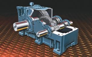
2 BE #1 WITH ONE The Falk name has earned a reputation for more than 100 years of delivering the highest value gear drive solutions in the power transmission industry. Carrying on with this tradition is the Drive One product family of gear drives. Its robust yet elegant design incorporates the features and benefits of past designs and leads the industry with innovation derived from our experience with heavy industry s most demanding applications. Anywhere you are the World, Drive One should be your first choice in geared power transmission equipment. Number One in Features Rugged design - ductile iron housings Precision - ground carburized gearing. Proven seal designs Internal oil distribution system. Easy oil level checking Number One in Benefits Stands up to the toughest environments Long life and quiet operation inimizes leaks Long bearing life and cooling running drives Extends oil/drive life Know-How & Customer Service People: 24/7 support Field service Problem solving support Information: Detailed selection guides Service/parts literature Complete online reference material Worldwide Exceptional worldwide availability and rebuild service centers reduce downtime and spare parts requirements 3 Year Heavy Duty Warranty Distributor+ Added Value Project coordination Installation assistance Field support Spares planning Customer in-plant knowledge 2

3 Conveyor Solutions Alignment-Free: Eliminates alignment at motor coupling and at driven equipment. Rugged motor flange accommodates standard TDand IEC flanged motors with fluid or standard couplings. Swing Base: ost flexible design, handles widest assortment of motor / coupling combinations. Bucket Elevator: Inching drive package designed for low maintenance, long life, & safety. Shaft ounted: Large sump capacity eliminates the need for cooling devices on most applications. Standard TA Taper Bushing provides great flexibility to suit inch or metric driven shafts. TA Taper bushings are the easiest on and easiest off solution in the industry. aterial Handling Alignment Free aterial Handling Swing Base aterial Handling Bucket Elevator Shaft-ounted with V-Belt Package Pump & Paper Solutions Single Reduction: A compact drive designed for low ratios, high power, and high speeds. Pre- Engineered cooling packages ensure cool running. Low Ratio / High Thermal: The optional low ratio / high thermal drives provide oversize sumps to offer "No- Cooling" alternatives. Pump & Paper Single reduction Pump & Paper Low Ratio/ High Thermal 3
4 The Complete Solution otorized: Standard brackets, motor adapters, and motor mounts accept NEA and IEC motor frames. High Ratio: Compound drives using Ultramite primary drives enable unlimited ratio availability. High Torque: Planetary final stage provides a compact, cost-effective alternative to hydraulic and conventional drives. ixer: Parallel and Right Angle Vertical drives offer drywell assembly and positive lubrication of upper bearings. otorized otor Bracket otorized otor Adaptor High-Ratio Parallel High-Ratio Right Angle High Torque Planetary Output ixer Parallel Vertical ixer Right Angle Vertical Quick-Change Replacement Drives... Replace All Types and Brands with Drive One! Right-Angle New Falk Replacement Drive Optional Guard Custom Transition Base Benefits: Improve performance & operating life Cost savings - up to 65% over obsolete equipment Better unit & parts availability Easy drop-in replacement 3-year heavy duty warranty The alternative to: Expensive obsolete drives Hard-to-get imported components Problem applications Parallel Vertical Concentric Shaft- ounted New Falk Replacement Drive New Falk Replacement Drive Falk otor Bracket, Optional Coupling & Guard New Falk Replacement Drive Optional Guard New Falk Replacement Drive Custom Transition Base Custom Transition Base Falk Interchange Hub Falk otor Bracket, Optional Coupling & Guard Custom Transition Base Falk TA Taper Bushing 4
5 Selection Guide , July 2007 Table of Contents Basic Information...5 Conditions Affecting Selection....6 echanical Service Factors How to Select...9 Thermal Factors & Procedures Selection Examples Accessory & Option Information Nomenclature...16 How to Order...17 Parallel Shaft Type DHB, DHF, DHP, DHJ, DHC, DHT, DVA, DVC, DV Gear Drives Assemblies & Rotations & 119 Power & Torque Ratings & 120 Basic Thermal Ratings & 120 LS Shaft Overhung Loads & Thrust Capacities Exact Ratios & 120 WR Dimensions & Right Angle Shaft Type DBB, DBF, DBJ, DBC, DBP, DBT, DXA, DXC, DX, DZC, DZT Gear Drives Assemblies & Rotations & 124 Power & Torque Ratings & 125 Basic Thermal Ratings & 125 Exact Ratios & WR & 125 Dimensions & Accessories Conversion Factors Factory Warranty We re so confident in the performance and reliability of our latest generation of Falk gear drives that we re backing this comprehensive offering with the best standard warranty in the business. Our full, 3-year Heavy-Duty Warranty provides shaft-to-shaft protection on all Falk components including bearings and seals (warranty extends for 3 years from date of shipment). It s an industry first... and one more powerful reason why Rexnord is your ultimate bottom-line value. Basic Information Safety Notes Falk Gear Drives The Falk and Rexnord name on the gear drive is the purchaser s assurance that the drive was engineered, rated and manufactured to sound design practices. The power supplied to the geared drive must be equal to or less than the power for which the drive was selected using the appropriate mechanical service factor for the application. The customer must assume the responsibility of isolating the gear drive from any vibratory or transient load induced by the driven equipment. Install and operate Rexnord products in conformance with applicable local and national safety codes and per Rexnord installation manuals which are shipped with gear drives and are also available upon request. Suitable guards for rotating members may be purchased from the Factory as optional accessories. Contact your local Rexnord district office for complete details. Copyright 2001, 2007, Rexnord Industries, LLC. All Rights Reserved. Litho in U.S.A. ONE, RENEW, REXNORD, and STLFLEX, are registered trademarks. Falk is a trademark of Rexnord. The contents of this selection guide are subject to change without notice or obligation. Information contained herein should be confirmed before placing orders. People Conveying Equipment Selection of Rexnord gear drives for applications whose primary purpose is the transportation of people is not approved. This includes such applications as freight or passenger elevators, escalators, man lift platforms and ski tows and ski lifts. If the primary purpose of the application is material conveyance and occasionally people are transported, the Rexnord warranty may remain in effect provided the design load conditions are not exceeded and certification to the appropriate safety codes and load conditions has been obtained by the system designer or end user from the appropriate enforcement authorities. Gear Drive echanical Power Ratings Gear drive mechanical power ratings stated in this selection guide allow 100% overload for starting loads and momentary overloads associated with normal electric motor driven standard applications operating 10 hours per day under uniform conditions, applications where the recommended mechanical service factor per Page 7 or 8 of this selection guide is 1,00, and where the actual mechanical service factor of the gear drive versus full motor rated power is equal to or greater than 1,00. For other standard applications not meeting conditions stated in the previous paragraph, determine the appropriate mechanical service factor from Page 7 or 8, then calculate an equivalent power by multiplying the actual power transmitted by the previously determined mechanical service factor. For these applications, the mechanical power rating of the gear drive selected must equal or exceed the equivalent power that has been calculated. For non-standard applications, those where excessive overloads, reversing service, mechanical brakes, or oversize prime movers are present, refer to Page 6, Conditions Affecting Selection, for special instructions. Gear Drive Basic Thermal Ratings Gear drive basic thermal ratings stated in this selection guide are based on the following assumed conditions: Ambient temperature is 25 C (77 F). Altitude is between sea level and 750 meters. Ambient air velocity is between 0,5 m/s and 1,4 m/s typical of a large indoor room. Duty cycle is continuous. Orientation is floor mounted with shafts in same horizontal plane. Thermal Factors & Procedures, Page 10, permit the calculation of an application adjusted thermal rating for the gear drive when local thermal conditions are different than those stated above. It is not necessary to apply the mechanical service factor to the basic thermal rating when determining the thermal adequacy of a gear drive. Interpolation of Gear Drive echanical Power Ratings and Torque Ratings When the high speed shaft rpm for an actual application falls between two tabulated high speed shaft rpm s found in the selection tables, interpolate to determine gear drive rating. Stored and Inactive Drives Each gear drive is spin-tested with a rust preventive oil that will protect parts against rust for a period of 4 months in an outdoor shelter or 12 months in a dry building after shipment from the Factory. Periodically inspect stored or inactive drives and spray internal parts with rust inhibitor every six months or more often, if necessary. Drain oil before adding rust inhibitor. Indoor dry storage is recommended. Drives ordered for extended storage can be treated at the Factory with a special preservative and sealed to rust-proof parts for periods longer than those cited above, if specified on the order. Refer to Service anual for preparation of stored and inactive gear drives. Rexnord Industries, L.L.C., 2001, ( ) 5
6 Conditions Affecting Selection Non Standard Selection Procedures Some applications require special procedures, or are refer to Factory. Excessive Overloads The maximum momentary or starting load applied to the gear drive must not exceed 200% of the rated load capacity of the gear drive (100% overload). Rated load capacity of the gear drive is defined as the power rating published in this selection guide with a mechanical service factor of 1,00. If the actual maximum momentary or starting load exceeds the conditions stated above, calculate an equivalent input power associated with the excessive overload by dividing the maximum overload by two. The gear drive selected must have a rated load capacity equal to or greater than the equivalent input power. Frequency of Starts Starting frequency is an important consideration when selecting a gear drive. Applications involving 2 to 3 equally spaced starts per hour must utilize a minimum 1,5 service factor for unloaded starts, and a minimum 1,75 service factor for fully loaded starts. For applications involving more than 3 starts per hour, refer to Factory the application specifics such as starting frequency and maximum starting torque. AC motors also have similar limitations. The addition of a fluid coupling as a soft start device would increase the number of allowable starts. Reversing Service Applications involving either more than 20 reversals per 10 hour period, or less than 20 reversals per 10 hour period with peak torques greater than 200% of normal load must be referred to Factory. Brake Equipped Applications When a gear drive is equipped with a working brake that is used to decelerate the motion of the system and the brake is located between the prime mover and the gear drive, select the gear drive based on the brake rating or the highest equivalent input power, whichever is greater. If the brake is used for holding only and is applied after the motion of the system has come to rest, the brake rating must be less than 200% of the rated load capacity of the gear drive selected for the application. If the brake rating is greater than 200% of the rated load capacity, refer the application to the Factory. Also refer to the Factory all applications in which the brake is located at the output shaft of the gear drive. Oversize Prime overs Recommended echanical Service Factors do not cover applications that require oversize prime movers for high energy or peak loads. Refer such applications to Falk for selection of suitable gear drives. Speed Variation or ulti-speed Applications The gear drives offered in this selection guide are designed to operate with splash lubrication on any single speed application and any ratio shown in the selection guide unless otherwise noted. It is essential that all orders indicate the operating speed requirements and ratio so that the proper internal oil distribution accessories can be supplied for the specific speed. Falk gear drives use different oil levels for various gear drive sizes, speeds and ratios. Consequently, to operate an existing gear drive at different speeds from those shown on the nameplate, full application and nameplate information must be referred to the Factory for review of the lubrication system. All variable or multi-speed applications will be referred to the Engineering Department to specify lubrication components for adequate lubrication at the slowest speed, without excessive temperature or churning at the highest speed. It is essential that all orders indicate minimum and maximum speeds, as well as the speed duration cycles. A separate motor-driven oil pump (at an extra charge) may be required. When selecting gear drives for multi-speed or variable speed applications, determine the speed at which the greatest torque is developed and select the gear drive on this basis. If the speed is not listed in the selection table, interpolate to determine the gear drive rating. Application Adjusted Thermal Rating, Page 10, The Application Adjusted Thermal Rating is the actual power that a gear drive will transmit continually for 3 hours or more without overheating. Although it is not necessary to apply the mechanical service factor when determining thermal adequacy of a gear drive, the Application Adjusted Thermal Rating considers thermal factors associated with the application that will affect the ability of the gear drive to dissipate thermal energy. These thermal factors include ambient temperature, altitude above sea level, ambient air velocity, inlet water temperature (when cooling tubes are offered), gear drive orientation and duty cycle. Thermal factors on Page 10 are used to adjust the Basic Thermal Rating when determining the Application Adjusted Thermal Rating. A check of the application adjusted thermal rating versus the actual power transmitted is necessary for the following applications: Continuous duty application where the gear drive runs continuously without shutdown for 3 hours or more per day. Intermittent duty applications where the gear drive operates for 3 hours or more per day, and run time intervals exceed the duration of the immediately following shutdown intervals. If any run time interval equals or exceeds 3 hours, the application is considered continuous duty. The duty cycle factor permits an upward adjustment of the basic thermal rating associated with intermittent duty applications above, and takes into account simply the % operating time per hour of the gear drive, regardless of duration relationship between run time intervals and down time intervals, and provided no specific run time interval exceeds one hour in duration. Other short interval intermittent duty applications, not meeting criteria stated above, may generate only modest thermal energy to be dissipated by the gear drive. Refer full application details to the Factory for selection of the minimum cooling method that is adequate. Effects of Solar Energy If a drive operates in the sun at ambient temperatures over 38ºC (100ºF), then special measures must be taken to protect the drive from solar energy. This protection can consist of a canopy over the gear drive or reflective paint on the gear drive. If neither is possible, a heat exchanger or other cooling device may be required. Overhung Loads and Thrust Loads Overhung loads and thrust loads must be taken into account when selecting a gear drive. If either an overhung load or thrust load is imposed on the gear drive, or if both an overhung load and thrust load are applied simultaneously, refer application details to the Factory for correct gear drive selection. Product odifications The Factory can supply special product modifications to suit your application needs. Contact your local Representative for housing modifications, special ratios, special shafts, special mounting orientations, accessory modifications and other special application requirements. Seal Housing Grease All gear drives will be shipped with Falk LTG grease in the seal housing cavities. Where this grease could contaminate products produced by customer processes, such as in the food and drug industries, clearly indicate on your purchase order that, Gear drive seal housing cavities must not contain grease. Oil Pump Equipped Application When a gear drive is equipped with an external motor driven oil pump, and the ambient temperature falls below 10 C (50 F), or the oil viscosity is in excess of 8000 SSU, an oil heater may be required to maintain a satisfactory flow rate at startup to prevent bearing failure. Consult the Factory. 6 ( ) Rexnord Industries, L.L.C., 2001, 2007.
7 Table 1 Table 2 or 3 3 to 10 Hour Service Factor echanical Service Factor conversions 3 to 10 Hours per Day ulti-cyl. Engine Over 10 Hours per Day ulti-cyl. Engine Intermittent Up to 3 Hours per Day otor ulti-cyl. Engine 1,00 1,25 1,50 1,00 1,00 1,25 1,50 1,75 1,00 1,25 1,50 1,75 2,00 1,25 1,50 1,75 2,00 2,25 1,50 1,75 2,00 2,25 2,50 1,75 2,00 For applications operating one half hour or less per day and applications driven by single cylinder engines, refer to the Factory. These service factors are based on the assumption that the system is free from serious critical and torsional vibrations and that maximum momentary or starting loads do not exceed 200% of the normal load. Occasional and intermittent service or engine driven applications For multi-cylinder engine driven applications and all applications operating intermittently up to 3 hours per day, refer to Table 2 or 3 for the Service Factor of the same application operating 3 to 10 hours per day. Next, in the first column of Table 1, find this same Service Factor in bold face type. Then, to the right, under the desired hours service and prime mover, locate the converted Service Factor. For example, from Table 3, the Service Factor is 1,25 for a uniformly loaded belt conveyor. From Table 1, for the same application the following are the Service Factors for various conditions. 1. Engine driven 3 to 10 hours per day; use 1,50 Service Factor. 2. Engine driven up to 3 hours intermittently; use 1,25 Service Factor. 3. otor driven up to 3 hours intermittently; use 1,00 Service Factor. OUNTING POSITION Standard mounting positions for types DH & DB are with the input and output shafts horizontal and for DV & DX with the output shafts vertical. Allowable mounting angles for standard oil levels are; Bridge Slope DH & DB 0 Up & 4 Down 1.5 Consult the Factory for other angles. Drawing Symbols Thy following symbols are used throughout the dimensioned drawings. =OILDIPSTICK =BREATHER =OILFILL =OILDRAIN echanical Service Factors Table 2 listed by industry for electric motor, steam turbine or hydraulic motor drives... recommendations are INIU and normal conditions are assumed. Service Industry 3to 10 Over 10 Hour Hour BOTTLING AND BREWING Bottling achinery... 1,00 1,25 Brew Kettles, Continuous Duty 1,25 1,25 Can Filling machines... 1,00 1,25 Cookers Continuous Duty 1,25 1,25 ash Tubs Continuous Duty 1,25 1,25 Scale Hoppers Frequent Starts 1,25 1,50 CLAY WORKING INDUSTRY Brick Press... 1,75 2,00 Briquette achines.... 1,75 2,00 Clay Working achinery.. 1,25 1,50 Pug ills... 1,25 1,50 DISTILLING.... See Brewing DREDGES Cable Reels, Conveyors... 1,25 1,50 Cutter Head, Jig Drives & Pumps 2,00 2,00 aneuvering Winches... 1,75 2,00 Screen Drives... 1,75 2,00 Stackers, Utility Winches... 1,25 1,50 FOOD INDUSTRY Beet Slicers... 1,25 1,50 Bottling, Can Filling achine 1,00 1,25 Cereal Cookers... 1,00 1,25 Dough ixers, eat Grinders 1,25 1,50 LUBER INDUSTRY Barkers Spindle Feed... 1,25 1,50 Barkers ain Drive... 1,75 1,75 Carriage Drive... Refer to Factory Conveyors Burner... 1,25 1,50 ain or Heavy Duty... 1,50 1,50 ain Log... 1,75 2,00 Re-Saw erry-go-round.. 1,25 1,50 Slab.... 1,75 2,00 Transfer... 1,25 1,50 Chains Floor... 1,50 1,50 Chains Green... 1,50 1,75 Cut-Off Saws Chain & Drag 1,50 1,75 Debarking Drums... 1,75 2,00 Feeds Edger.... 1,25 1,50 Feeds Gang.... 1,75 1,75 Feeds Trimmer.... 1,25 1,50 Log Deck... 1,75 1,75 Log Hauls Incline, Well Type 1,75 1,75 Log Turning Devices... 1,75 1,75 Planer Feed... 1,25 1,50 Planer Tilting Hoists... 1,50 1,50 Rolls Live Off Bearing Roll Cases... 1,75 1,75 Sorting Table, Tipple Hoist. 1,25 1,50 Transfers Chain & Craneway 1,50 1,75 Tray Drives.... 1,25 1,50 Veneer Lathe Drives.... Refer to Factory OIL INDUSTRY Chillers... 1,25 1,50 Oil Well Pumping... Refer to Factory Paraffin Filter Press... 1,25 1,50 Rotary Kilns... 1,25 1,50 PAPER ILLS Agitator (ixer) ,50 Agitator for Pure Liquids ,25 Barking Drums, Barkers ech.... 2,00 Beater ,50 Breaker Stack ,25 Calender ,25 Chipper ,00 Chip Feeder ,50 Coating Rolls ,25 Conveyors Chip, Bark, Chemical ,25 Log (incl. Slab) ,00 Couch Rolls ,25 Cutter ,00 Cylinder molds ,25 Dryers Paper ach. & Conveyor Type... 1,25 Embosser ,25 Extruder ,50 Industry Service 3to Over Hour Hour Fourdrinier Rolls Lumpbreaker, Wire Turning Dandy & Return Rolls ,25 Jordan ,50 Kiln Drive ,50 t. Hope & Paper Rolls ,25 Platter ,50 Presses (Felt & Suction) ,25 Pulper (Continuous) ,00 Repulper (Heavy Shock) ,00 Reel (Surface Type) ,25 Screens Chip & Rotary ,50 Vibrating ,00 Size Press ,25 Super Calenders ,25 Thickener & Washer AC otor ,50 DC otor ,25 Vacuum Pumps ,50 Wind & Unwind Stand ,25 Winders (Surface Type) ,25 Yankee Dryers ,25 PLASTIC INDUSTRY Batch Drop ill, 2 smooth rolls 1,25 1,25 Calenders... 1,50 1,50 Compounding ills... 1,25 1,25 Continuous Feed, Holding & Blend ill.... 1,25 1,25 Extruders... 1,50 1,50 Variable Speed Drive... 1,50 1,50 Fixed Speed Drive... 1,75 1,75 Intensive Internal ixers Batch ixers... 1,75 1,75 Continuous ixers... 1,50 1,50 RUBBER INDUSTRY Batch Drop ill, 2 smooth rolls 1,50 1,50 Calenders... 1,50 1,50 Cracker, 2 corrugated rolls. 2,00 2,00 Cracker Warmer 2 roll, 1 corrugated roll.... 1,75 1,75 Extruders Continuous Screw Operation 1,75 1,75 Intermittent Screw Operation 1,75 1,75 Holding, Feed & Blend ill 2 Roll... 1,25 1,25 Intensive Internal ixers Batch ixers... 1,75 1,75 Continuous ixers... 1,50 1,50 ixing ill 2 smooth rolls (if corrugated rolls are used, use Cracker Warmer service factors)... 1,50 1,50 Refiner 2 roll... 1,50 1,50 SEWAGE DISPOSAL Bar Screens... 1,25 1,25 Chemical Feeders... 1,25 1,25 Collectors... 1,25 1,25 Dewatering Screens... 1,50 1,50 Scum Breakers... 1, Slow or Rapid ixers... 1,50 1,50 Thickeners... 1,50 1,50 Vacuum Filters... 1,50 1,50 SUGAR INDUSTRY Cane Knives, Crushers ,75 ills (low speed end) ,75 TEXTILE INDUSTRY Batchers, Calenders... 1,25 1,50 Card achines... 1,25 1,50 Dry Cans, Dryers... 1,25 1,50 Dyeing achinery... 1,25 1,50 Knitting achinery... Refer to Falk Looms, angles, Nappers, Pads... 1,25 1,50 Range Drives.... Refer to Factory Slashers, Soapers, Spinners, Tenter Frames, Washers, Winders... 1,25 1,50 WINDLASS.... Refer to Factory Service Factors for paper mill applications are applied to the nameplate rating of the electric drive motor at the motor rated base speed and are consistent with those shown in TAPPI standards. Anti-friction bearings only. A service factor of 1,00 may be applied at base speed of a super calender operating over a speed range of part constant power and part constant torque where the constant power speed range is greater than 1,5 to 1. A service factor of 1,25 is applicable to super calenders operating at constant torque over the entire Rexnord Industries, L.L.C., 2001, ( ) 7
8 Table 3 echanical Service Factors listed by application for electric motor, steam turbine or hydraulic motor drives... recommendations are INIU and normal conditions are assumed Application Service 3to 10 Hour Over 10 Hour AGITATORS Pure Liquids Liquids & Solids Liquids-Variable Density APRON CONVEYORS Uniformly Loaded or Fed Heavy Duty APRON FDERS ASSEBLY CONVEYORS Uniformly Loaded or Fed Heavy Duty BALL ILLS...See ills. Rotary BARGE HAUL PULLERS BARKING Drums (Coupling Connected) echanical BAR SCRNS (Sewage) BATCHERS (Textile) BELT CONVEYORS Uniformly Loaded or Fed Heavy Duty BELT FDERS BENDING ROLLS (achine) BLOWERS Centrifugal Lobe Vane BOTTLING ACHINERY BREWING... See Table 2 BRICK PRESS (Clay Working) BRIQUETTE ACHINES (Clay Working) BUCKET Conveyors Uniform Conveyors Heavy Duty Elevators Continuous Elevators Uniform Elevators Heavy Duty CALENDERS Rubber and Plastic... See Table 2 Textile CANE KNIVES CAN FILLING ACHINES CARD ACHINES (Textile) CAR DUPERS CAR PULLERS CNT KILNS...See ills. Rotary CENTRIFUGAL Blowers, Compressors, Discharge Elevators, Fans or Pumps CHAIN CONVEYORS Uniformly Loaded or Fed Heavy Duty CHEICAL FDERS (Sewage) CLARIFIERS CLASSIFIERS CLAY WORKING... See Table 2 COLLECTORS (Sewage) COPRESSORS Centrifugal Lobe Reciprocating. ulti-cylinder Single-Cylinder CONCRETE IXERS Continuous Intermittent Application Service 3to 10 Hour Over 10 Hour CONVEYORS Uniformly loaded or Fed: Apron or Bucket Assembly, Belt, Chain, Flight, Oven, Screw CONVEYORS Heavy Duty. Not Uniformly Fed Apron, Assembly, Belt, Bucket, Chain, Flight, Oven, Screw CONVEYORS Severe Duty Live Roll... Refer to Factory Reciprocating Shaker COOKERS (Brewing & Distilling), (food) COOLING TOWER FANS Refer to Factory CRANES Dry Dock Cranes, ain Hoist, Bridge and Trolley Travel.. Refer to Factory CRUSHERS Ore or Stone Sugar DEWATERING SCRNS (Sewage) DISC FDERS DISTILLING.... See Table 2 DOUBLE ACTING PUPS 2 or more Cylinders Single Cylinder...Ṙefer to Factory DOUGH IXER (Food) DRAW BENCH (etal ills) Carriage & ain Drive DREDGES... See Table 2 DRY DOCK CRANES... Refer to Factory DRYERS & COOLERS (ills. Rotary) DYEING ACHINERY (Textile) ELEVATORS Bucket-Uniform Lood Bucket-Heavy Duty Bucket-Continuous Centrifugal Discharge Escalators... Not Approved Freight... Not Approved Gravity Discharge an Lifts, Passenger... Not Approved EXTRUDERS (Plastic & Rubber)... See Table 2 FANS Centrifugal Cooling Towers.... Refer to Factory Forced Draft Induced Draft Large (ine. etc.) Large lndustrial Light (Small Diameter) FDERS Apron. Belt Disc Reciprocating Screw FLIGHT CONVEYORS Uniform Heavy FOOD INDUSTRY... See Table 2 GENERATORS (Not Welding) GRAVITY DISCHARGE ELEVATORS HAER ILLS HOISTS Heavy Duty edium Duty Skip Hoist Application Service 3to 10 Hour Over 10 Hour INDUCED DRAFT FANS KILNS...See ills. Rotary LAUNDRY WASHERS LAUNDRY TUBLERS LINE SHAFTS Driving Processing Equipment Other Line Shafts, Light LIVE ROLL CONVEYORS Refer to Factory LOBE BLOWERS OR COPRESSORS LOG HAULS (Lumber) Incline-well Type LOOS (Textile) LUBER INDUSTRY... See Table 2 ACHINE TOOLS Auxiliary Drives Bending Rolls ain Drives Notching Press (Belted)... Refer to Factory Plate Planers Punch Press (Geared) Tapping machines ANGLE (Textile) ASH TUBS (Brewing & Distilling) EAT GRINDERS (Food) ETAL ILLS Draw Bench Carriages & ain Drives Pinch, Dryer & Scrubber Rolls, Reversing...Ṙefer to Factory Slitters Table Conveyors. Non-Reversing Group Drives Non-Reversing Individual Drives Reversing... Refer to Factory Wire Drawing & Flattening achines Wire Winding achines ILLS. ROTARY Ball and Rod ills with Spur Ring Gear with Helical Ring Gear Direct Connected Cement Kilns, Dryers & Coolers Pebble, Plain & Wedge Bar ills Tumbling Barrels IXER (Also see Agitators) Concrete, Cont. & lnt Constant Density Variable Density NAPPERS (Textile) OIL INDUSTRY... See Table 2 ORE CRUSHERS OVEN CONVEYORS Uniform Heavy Duty PAPER ILLS... See Table 2 PASSENGER ELEVATORS.. Not Approved PEBBLE ILLS PLATE PLANERS PRINTING PRESSES.... Refer to Factory PROPORTIONING PUPS PUG ILLS (Clay) PULLERS (Barge Haul) Application Service 3to 10 Hour Over 10 Hour PUPS Centrifugal Proportioning Reciprocating Single Act., 3 or more Cyl Double Act., 2 or more Cyl Single Act., 1 or 2 Cyl.. Refer to Factory Double Acting, 1 Cyl... Refer to Factory Rotary: Gear, Lobe, Vane PUNCH PRESSES (Gear Driven) RECIPROCATING Conveyors & Feeders RECIPROCATING COPRESSORS ulti-cylinder Single Cylinder ROD ILLS... See ills. Rotary ROTARY Pumps Screens (Sand or Gravel) RUBBER & PLASTICS INDUSTRIES... See Table 2 SAND ULLERS SCRNS Air Washing Rotary Sand or Gravel Traveling Water Intake SCREW CONVEYORS Uniform Heavy Duty or Feeder SCU BREAKERS (Sewage) SEWAGE DISPOSAL.... See Table 2 SHAKER CONVEYORS SHTERS (Rubber) SINGLE ACTING PUP I or 2 Cylinders... Refer to Factory 3 or more Cylinders SKI TOWS & LIFTS... Not Approved SKIP HOIST SLAB PUSHERS SLITTERS (etal) SLUDGE COLLECTORS (Sewage) SOAPERS (Textile) SPINNERS (Textile) STRING GEARS... Refer to Factory STOKERS STONE CRUSHERS SUGAR INDUSTRY.... See Table 2 TABLE CONVEYORS (Non-Reversing) Group Drives Individual Drives Reversing... Refer to Factory TENTER FRAES (Textile) TEXTILE INDUSTRY... See Table 2 THICKENERS (Sewage) TUBLING BARRELS VACUU FILTERS (Sewage) VANE BLOWERS WINCHES (Dredges) WINDERS (Textile) WINDLASS...Ṛefer to Factory WIRE Drawing achines Winding achines Selection of Falk products for applications whose primary purpose is the transportation of people is not approved. This includes such applications as freight or passenger elevators, escalators, man lifts, work lift platforms and ski tows and ski lifts. If the primary purpose of the application is material conveyance and occasionally people are transported, the Factory warranty may remain in effect provided the design load conditions are not exceeded and certification to the appropriate safety codes and load conditions has been obtained by the system designer or end user from the appropriate enforcement authorities. Contact the Factory for proper selection of a mixer drive. 8 ( ) Rexnord Industries, L.L.C., 2001, 2007.
9 How to Select Before making a selection, refer to Basic Information and Conditions Affecting Selection on Pages 5 and 6. Information Required The following basic information is required to select a Drive One gear drive for your application. Prime over Data Type electric or hydraulic motor or engine Power rating in kw or hp Speed constant or variable Dimensions if Falk will furnish motor mounting accessory or coupling Driven achine Data Type conveyor, kiln, etc. Power demand in kw, or hp, or equivalent torque. Speed and direction of rotation Service Hours per day; reversals per minute if reversing; minutes per hour (duty cycle) if not continuous Gear Drive Data Type parallel shaft or right angle Horizontal or vertical output shaft Ambient temperature at drive location Altitude above sea level Ambient air velocity at drive location ounting position if inclined or non-standard orientation Shaft Connections Shaft diameters and key sizes Overhung loads provide full description of sheave, sprocket, or pinion Thrust load and direction Power Selection ethod The power selection method is based on the power rating of the prime mover. 1. Determine the mechanical service factor. Electric motor driven applications, see Tables 2& 3, Pages7& 8. Engine driven or intermittent applications, see Table 1, Page Calculate equivalent power by multiplying the rated power of the prime mover by the mechanical service factor determined in Step Determine gear drive nominal ratio. Divide the high speed shaft rpm by the low speed shaft rpm to determine your ideal ratio. Choose a nominal ratio that most closely approximates your ideal ratio. Nominal ratios are found in the power ratings tables, see Step Using the equivalent power determined in Step 2, and the gear drive nominal ratio that most closely approximates the ideal ratio determined in Step 3, select the gear drive size using the Power Ratings Tables. Power Ratings Tables: Parallel shaft gear drives, see Pages 22 thru 33 & 114. Right angle shaft drives, see Pages 78 thru 85 & 119. Locate the proper page within the power ratings tables based on nominal ratio and high speed shaft rpm. Once on the proper page, go to the portion of the table associated with your high speed shaft rpm, and using the appropriate nominal ratio, trace to the right through the columns. Determine the column of the first power rating that equals or exceeds the equivalent power determined in Step 2. The size of the gear drive selected is at the top of the column. Once a gear drive size has been selected, an exact ratio can be determined from the exact ratio tables. 5. Check thermal rating using procedures outlined on Page 10. The application adjusted thermal rating of the cooling method selected must equal or exceed the actual power transmitted. 6. When overhung loads or thrust loads are present, check to assure they are within the capacity of the gear drive selected. Overhung load (radial load) is imposed by sheaves, sprockets, and open pinions that are mounted directly on the shaft extensions of the gear drive. Gear drive shaft extensions that are flexible coupling connected need not be checked for overhung load, flexible couplings do not impose significant overhung load. Refer H.S. Shaft overhung load applications to the Factory. Thrust load (axial load) applied to the gear drive is unusual. In these applications, the magnitude of the thrust load, and the direction of thrust load, is supplied by the system designer. Thrust loads must be within the capacity of the gear drive. Refer thrust load applications to the Factory. Complex shaft loadings involving simultaneous application of overhung load, thrust load, or bending moment (as in mixers and agitators) should be referred directly to the Factory. Torque Selection ethod For convenience, low speed shaft torque ratings of gear drives are provided, and a purely mechanical selection of a gear drive can be made using torque values. Simply follow the steps outlined in the power selection method, substituting torque values for power values. In order to check thermal adequacy, and check shaft ratings, it will be necessary to convert the torque to power using the appropriate formula below: Torque (Nm) x Output Speed (rpm) Input Power (kw) = 9550 Example Selections An example using the Power Selection ethod and an example using the Torque Selection ethod is found on Page 11. Rexnord Industries, L.L.C., 2001, ( ) 9
10 Thermal Factors & Procedures Checking Thermal Rating Checking the thermal rating is extremely important. If the gear drive s capacity to dissipate thermal energy is insufficient, it will overheat, and severe damage may occur. Gear drive basic thermal ratings are defined on Page 5. A discussion of application adjusted thermal rating, and when it is applicable, is found on Page 6. Thermal Rating Factors Thermal horsepower ratings published herein are based on a 25 C(77 F) ambient temperature at sea level. For other conditions, the thermal horsepower rating must be multiplied by the factors shown in Tables 1&2. Application Adjusted Thermal Rating Once a mechanically adequate gear drive selection has been made per Steps 1-4 on Page 9, determine the application adjusted thermal rating of the gear drive. The application adjusted thermal rating of the gear drive selected must equal or exceed the actual power transmitted. In most cases, the nameplate power rating of the motor is assumed to equal the actual power transmitted. It is not necessary to apply the mechanical service factor when determining thermal adequacy of a gear drive. Use the following formula to determine application adjusted thermal rating: P TA =P T xb 1 xb 2 xb 3 xb 4 xb 5 where: P TA = Application Adjusted Thermal Rating P T = Basic Thermal Rating B 1 = Ambient Temperature Factor (Table 1) B 2 = Altitude Factor (Table 2) B 3 = Ambient Air Velocity Factor (Table 3) B 4 = Duty Cycle Factor (Table 4) B 5 = Orientation Factor (Table 5) Basic Thermal Ratings for parallel shaft gear drives are found on Pages Basic Thermal Ratings for right angle shaft gear drives are found on Pages For the gear drive you have selected mechanically, choose an auxiliary cooling method whose application adjusted thermal rating equals or exceeds the actual power transmitted. If no listed cooling method is adequate, contact the Factory for selection of an optional heat exchanger, or consider a larger gear drive with greater thermal capacity. TABLE 1 Ambient Temperature Factor B 1 (For all cooling methods) Ambient Temperature Factor with no Auxiliary Cooling or with Fan 10 C 1,17 15 C 1,12 20 C 1,06 25 C 1,00 30 C 0,94 35 C 0,88 40 C 0,81 45 C 0,74 50 C 0,66 Factors for other ambient temperatures can be interpolated. TABLE 2 Altitude Factor B 2 (For air cooled methods, no cooling tubes) Altitude Above Sea Level eters Factor 0 1, , , , , , , ,68 TABLE 3 Ambient Air Velocity Factor B 3 (For no auxiliary cooling) Sustained Ambient Air Velocity m/s Installed Environment Factor for no Auxiliary Cooling < 0,5 Confined Space 0,75 0,5 to 1,4 Large Indoor Room 1,00 1,4 to 3,7 Large Indoor Room 1,40 > 3,7 Outdoors 1,90 The sustained ambient air velocity must be a continuous flow of air directly onto the gear drive. If the air flow cannot be relied upon to be continuous, an ambient air velocity factor of 1.00 must be used. TABLE 4 Duty Cycle Factor B 4 % Operating Time Per Hour Factor With or Without Auxiliary Cooling 100% 1,00 80% 1,05 60% 1,15 40% 1,35 20% 1,80 The duty cycle factor must be based on the percentage of each hour that the drive is operating. For example: a gear drive operating for 48 minutes of every hour of the day has an 80% duty cycle, but a drive operating for 4 hours and resting for 4 hours has a 100% duty cycle. Where the % Operating Time Per Hour falls between values tabulated above, use the next higher % Operating Time. TABLE 5 Orientation Factor B 5 - Horizontal Output Drives Only Input Speed rpm HS Shaft at Same Height as LS Shaft HS Shaft over LS Shaft LS Shaft over HS Shaft 1st Int Shaft over HS Shaft DH2 DH3 DB3 DH2 DH3 DZ3 DH2 DH3 DZ3 DH ,00 0,57 0, ,00 0,66 0, ,00 0,74 0, ,00 0,79 0, ,00 0,82 0, ,00 0,83 0, ,00 0,90 0,87 10 ( ) Rexnord Industries, L.L.C., 2001, 2007.
11 Power Selection Example A draw bench operates 10 hours per day. The gear drive required for the application is driven at the high speed shaft by a 75 kw electric motor at RP. A low speed shaft speed of 36 RP at the gear drive has been requested. Ambient temperature at the draw bench never exceeds 25 C. The draw bench is located in a small indoor room, with air flow less than 0,5 meters per second. Altitude above sea level is 150 meters. The high speed and low speed shafts of the selected gear drive will be connected to the driving and driven equipment by flexible couplings. Select a parallel shaft gear drive for this application as follows: 1. The mechanical service factor is 1,25 for a draw bench drive operating 10 hours per day, from Page 8, Table 3 (etal ills). 2. The equivalent power in kw = 1,25 x 75 = 93,75 kw. 3. The ideal ratio is = 27,78. The closest nominal ratio is 28,0:1 from the Double Reduction Power Ratings Table on Page Using the Double Reduction Power Ratings Table on Page 26, and in the section associated with a high speed shaft rpm of 1 000, and in the row associated with a nominal ratio of 28,0:1, trace right through the columns to the first power rating that equals or exceeds the equivalent power of 93,75 kw calculated in Step 2. The selection is a size 1170 (shown at the top of the column) that has a power rating of 121 kw. Actual mechanical service factor is = 1,61. Exact ratio is 27,86:1, found on Page 47 (exact ratio table) 5. Check thermal rating. The application adjusted thermal rating of the cooling method selected must equal or exceed the actual power transmitted (75 kw). Basic thermal rating for the size 1170DH2, nominal ratio 28,0:1, high speed shaft at RP, no auxiliary cooling, equals 171,0 kw, per Page 36. Thermal factors from Page 10 for no auxiliary cooling are as follows: B1 = Ambient Temperature Factor from Thermal Table 1 = 1,00 B2 = Altitude factor from Thermal Table 2 = 1,00 B3 = Ambient Air Velocity Factor from Thermal Table 3 = 0,75 B4 = Duty Cycle Factor from Thermal Table 4 = 1,00 B5 = Orientation factor from Thermal Table 5 = 1,00 Application Adjusted Thermal rating with no auxiliary cooling = 171,0 x 1,00 x 1,00 x 0,75 x 1,00 x 1,00 = 128,3 kw Application Adjusted Thermal rating does equal or exceed the 75 kw transmitted, no auxiliary cooling is required. 6. It is not necessary to check overhung load or thrust capacity of the gear drive for this example. Gear drive shaft extensions are connected by flexible couplings, which do not impose significant overhung load. No thrust load is present. Torque Selection Example A dredge utility winch requires Nm of torque at its output shaft, which operates at 16 RP. The winch is in service 10 hours per day and is driven by a coupling-connected 40 kw, rpm electric motor. The ambient temperature never exceeds 25º C. The approximate air velocity is 3,0 meters per second, and the dredge operates in the North Sea (sea level). The winch never operates more than 30 minutes in a given hour. The space available is best suited for a right angle gear drive. Select a gear drive for this application. 1. The Service Factor is 1,25 for a dredge utility winch operating 10 hours per day, from Page 7, Table 2 under Dredges. 2. The equivalent torque is 1,25 x = Nm 3. The ideal ratio is = 62,5. The nearest standard nominal ratio is 63,0 from the Right Angle Triple Reduction Table on Page Using the Triple Reduction Table on Page 82, in the RP high speed shaft section and at the 63,0:1 ratio and 16,0 rpm, trace right to 37,8 (x 1 000, the first torque exceeding the equivalent torque of Nm) and read the drive size 1170 at the top of the column. 5. The basic thermal capacity with no auxiliary cooling for an 1170DB3, 63,0:1, at RP from the table on Page 87 is 80 kw. The ambient temperature factor (B1) from Table 1, Page 10, is 1,00. The altitude factor (B2) from Table 2, Page 10 is 1,00. The ambient air velocity factor (B3) is 1,4 from Table 3, Page 10. The Duty Cycle is 50% (30 min / hour), so the duty cycle factor (B4) is 1,15 from Table 4, Page 10. The Orientation factor (B5) is 1,00, from Table 5, Page The application adjusted thermal capacity is 80 x 1,00 x 1,00 x 1,40 x 1,15 x 1,00 = 128,8 kw, which exceeds the power rating of the motor (40 kw). Therefore, no additional cooling is required. 7. It is not necessary to check overhung load or thrust capacity of the gear drive for this example. Gear drive shaft extensions are connected by flexible couplings, which do not impose significant overhung load. No thrust load is present. Rexnord Industries, L.L.C., 2001, ( ) 11
12 Accessory & Option Information Shaft Driven Cooling Fans See Pages Shaft driven cooling fans provide a simple and inexpensive way to utilize the full mechanical rating of gear drives by lowering the operating temperatures, thus increasing thermal power capacity. Cooling fans have been successfully used on electric motors and other related machinery for many years. They eliminate the need for water or electrically powered cooling, pumps, and external piping. The sound level at standard motor rpm is about the same as that from fans on totally enclosed, fan cooled driving motors. Less than 0.25% of cataloged power rating is required to drive the fans. Shaft driven fans are available for use with DH parallel shaft drives, DB & DZ right-angle drives and also DX vertical drives. Dimensions, arrangements, and clearances for shaft driven fans are shown in this selection guide. For applications requiring fan cooling and two usable H.S. shaft extensions (with inching drives, emergency drives, etc), consult the Factory. motor ratings, and thermostatic control wiring diagrams are also available from the Factory. Backstops See Pages 140 & 141 Backstops prevent reverse rotation or backrun without backlash for conveyors, elevator head shafts, and similar applications. The Drive One backstop is a sprag type design. The backstop shares the drive sump oil. Electric Cooling Fans See Pages Electric fans are unaffected by shaft rotation and speed, and includes a thermostatic control to turn the fan off when it is not required. The electric fan can be mounted on either end of a parallel shaft drive, and on the L.S. end of a right angle drive. This permits full use of available shaft extensions. Electric fans are available with the following standard motor packages: 60 Hz, 3-Phase, 220/380 VAC 60 Hz, 3-Phase, 265/460 VAC 50 Hz, 3-Phase, 220/380 VAC Other motor packages may be available at an extra charge. Consult the Factory for price and availability. Dimensions, arrangements, and clearances for electric fans are shown in this selection guide. Additional information, including 6000 GAX 6000 Factory Fill The gearing in Falk Drives factory filled with GAX 6000 is warranted for a period of 10 years from date of shipment against tooth failure or surface distress. GAX 6000 allows for extended change intervals and prevents the need for seasonal lubricant changes. Fulfills all Falk lubrication requirements Reduces energy consumption Decreases operating temperatures Provides superior viscosity stability Affords exceptional wear protection Extends gearing fatigue life Eliminates seasonal lube changes Reduces low-temp starting torque Reduces fluid maintenance and disposal costs Improved tolerance of water contamination 12 ( ) Rexnord Industries, L.L.C., 2001, 2007.
13 Accessory & Option Information otor Brackets See Pages 147 & 148 otor brackets may be used for Types DH and DB. These motor brackets provide an economical soft mounting for standard NEA T-frame and IEC B3 induction motors. It is expected that the weight, location, and starting torque of the motor will cause cantilevered motor brackets to deflect or twist to varying degrees. They are engineered to be within acceptable deflection limits as determined by the Factory. However, because the motor bracket is a soft motor support, deflection and vibration magnitudes of the bracket may exceed levels normally considered acceptable for rigidly, hard mounted machinery. Flange otor Adapters See Pages 145 & 146 Flanged motor adapters are available for Types DH and DB drives. This adapter allows a flange-mounted motor to be directly mounted to the high speed side of the drive. otor ounts See Pages 156 & 157 otor mounts are selectively pre-designed for Types DH and DB drives. otor mounts provide a convenient drive support for the motor when the drive is belt driven. For detailed information on motor mounts, contact the Factory. Bedplates A bedplate is recommended to insure proper alignment of a base mounted drive with the motor. Falk can provide fabricated steel bedplates for all popular sizes of standard Types DH and DB drives. These bedplates accommodate standard NEA and IEC motors within the power range of the drive and many of the larger non-nea motors. Special bedplates can be designed and manufactured for unique motor and special accessory combinations. Supports for tachometers, brakes, timing devices, foot-mounted fluid couplings, or other accessories can be added. Contact the Factory for further details on this accessory. Swing Base See Pages Swing bases have been pre-engineered for over 500 combinations of Drive One, NEA and IEC motors and Falk couplings. Finite element analysis has been performed to assure trouble-free operation. Designed specifically for use with the DBT right angle shaft mounted drive, the swing base provides an economical and readily available alternative to bedplates. Rexnord Industries, L.L.C., 2001, ( ) 13
Size 1120, Bore Ø0.75" Size 1320, Bore Ø1.25" Size 1420, Bore Ø1.375" 3/4HP. Size 1320, Bore Ø1.25" Size 1320, Bore Ø1.25" Size 1633, Bore Ø2.
 Product Range Hollow Shaft Type Selections shaded in blue offer an increased service factor. Please refer to the gearmotor selection tables for specific unit service factor details. Nominal Ratio (:1)
Falk Ultramite UC Helical Concentric Gear Drives
 Gear Catalog Download the most up-to-date versions at www.rexnord.com Falk Ultramite UC Helical Concentric Gear s (Inch) Falk Ultramite UC Helical Concentric Gear To learn more about the Falk Ultramite
Speed Reducers and Gearmotors
 and Gearmotors Table of Contents 1. General Information 2. How to Select...2.2 Configure a Model Number (Nomenclature)...2.4 AGMA Load Classifications...2.6...2.8 Single Reduction,,, Y3, Y5,...2.8 Single
Falk Type YB & GHB Horizontal Right Angle Gear Drives
 Falk Series YB & GHB Gear Drives Proven Performance for Thermal Capacity Applications (English Inch) Falk Type YB & GHB Horizontal Right Angle Gear Drives Since 1897, Falk gear drives have benefitted from
Catalog April Metric Motorized Torque-Arm II Technical catalog
 Catalog April 2015 Metric Motorized Torque-Arm II Technical catalog With expertise, and a comprehensive portfolio of products and life-cycle services, we help value-minded industrial customers improve
Falk Series Y & YF Gear Drives. Proven Performance for High Thermal Capacity Applications (English Inch)
") Falk Series Y & YF Gear Drives Proven Performance for High Thermal Capacity Applications (English Inch) Falk Series Y&YFParallel Gear Drives Since 1897, Falk gear drives have benefitted from specialized
Falk Series Y & YF Gear Drives Proven Performance for High Thermal Capacity Applications (English Inch) Falk Series Y&YFParallel Gear Drives Since 1897, Falk gear drives have benefitted from specialized
Series C Helical Worm
 Series C Helical Worm Technical p to - 45 Kw / 10,000 Nm Geared otors CC-2.01GB0914 PRODCTS IN THE RANGE Series A Worm Gear units and geared motors in single & double reduction types Series BD Screwjack
Catalog. MagnaGear XTR gear reducers Gearing
 Catalog MagnaGear XTR gear reducers Gearing We provide motors, generators and mechanical power transmission products, services and expertise to improve customers' processes and optimize the total cost
Maxum XTR Concentric reducers catalog
 MECHANICAL POWER TRANSMISSION Maxum XTR Concentric reducers catalog Maxum XTR Concentric reducers catalog To receive a copy of the Dodge Maxum XTR Catalog, Dodge Bearing Engineering Catalog, Dodge Gearing
CYCLO 6000 Gearmotors. How to Select. How to. Select. Cyclo 6000 Series. How to Select 2.1
 2 How to Select How to Select Cyclo 6000 Series How to Select 2.1 How to Select a Gearmotor Step 1: Step 2: Collect data about your application Before starting you need to know the: (e.g. Conveyor, Mixer,
Series P Planetary. Technical Up to - 90kW / 65000Nm. Planetary CP-2.00GB0 1
 VARIMAX AG, Antriebstechnik, Normannenstrasse 14, Postfach 762, CH-3018 Bern Tel. +41 (0)31 990 00 70 e-mail info@varimax.ch Fax +41 (0)31 990 00 71 web www.varimax.ch Series P Planetary Technical Up to
FALK ULTRAMITE Delivers Local Availability, NEMA/IEC Compatibility Plus Drop-in Replacement
 Falk Ultramite UB Right-Angle Gear Drive Delivering The Right Punch for Productivity (English-Inch) FALK ULTRAMITE Delivers Local Availability, NEMA/IEC Compatibility Plus Drop-in Replacement It s a winning
Cyclo Speed Reducers CATALOG
 Cyclo 6000 CATALOG 03.601.50.005 Cyclo 6000 Superior design, powerful performance The Cyclo 6000 is also available as an inline Gearmotor To request a catalog, or for more information on any of our high
Gear Coupling. Applications
 Gear Coupling Applications Power Transformation Print & Paper Industries Gear Boxes Textile Industries Conveyors Pumps Compressors Process, Chemical & Pharmaceutical Industries Nylon Gear Couplings Nylon
Series F Shaft Mounted Helical
 Series F Shaft ounted Helical Technical Up to - 110 kw / 16,500 Nm Geared otors CF-2.01GB1 ATEX Compliance Assured Total compliance with the ATEX Directive safeguarding the use of industrial equipment
FALK ULTRAMITE Delivers Local Availability, NEMA/IEC Compatibility Plus Drop-in Replacement
 Falk Ultramite UJ Shaft-Mounted Offset Helical Gear Drive Delivering The Right Punch for Productivity (English-Inch) FALK ULTRAMITE Delivers Local Availability, NEMA/IEC Compatibility Plus Drop-in Replacement
CONTENTS MAXUM Concentric Reducers
 CONTENTS s Features/Benefits.............................................. G3-2 Specifications................................................. G3-4 How to Order.................................................
Hyponic. Hypoid Right Angle Gearmotor and Reducer CATALOG
 Hypoid Right Angle Gearmotor and Reducer CATALOG 12.001.50.005 Hypoid Right Angle Patented, High-Performance Gearmotors and Reducers Featuring All-Steel Hypoid Gearing U. S. PAT. NO. 5,203,231; U.S. PAT.
Power Transmission Products. Maurey Couplings. Hi-Flex Tire Couplings Hi-Q Jaw Couplings Finished Bore Sleeve Couplings Rigid Bushed Sleeve Couplings
 Power Transmission Products Maurey Couplings Hi-Flex Tire Couplings Hi-Q Jaw Couplings Finished Bore Sleeve Couplings Rigid Bushed Sleeve Couplings Hi-Q Flexible Couplings R to enable full power transmission
SPECIFICATION HOW TO ORDER QUANTIS QUANTIS
 The DODGE speed reducer is suitable for c-face, separate, or integral gearmotor construction in either foot or output flange mountings, and available in single, double or triple ratios. The DODGE RHB and
Universal Joints. In This Section: D Type HD Type D Type Stainless NB (Needle Bearing) Type LOJ Type DD and DDX Type Universal Joint Boots
 Type LOJ Type DD and DDX Type Universal Joint Boots") JW Universal Joints In This Section: D Type HD Type D Type Stainless NB (Needle Bearing) Type LOJ Type DD and DDX Type Universal Joint Boots www.lovejoy-inc.com 329-1 JW Universal Joints Safety Warning
JW Universal Joints In This Section: D Type HD Type D Type Stainless NB (Needle Bearing) Type LOJ Type DD and DDX Type Universal Joint Boots www.lovejoy-inc.com 329-1 JW Universal Joints Safety Warning
The Strong Silent Type
 The Strong Silent Type Shaft Mount Speed Reducers SMR-15 Vortex Shaft Mount Reducers Engineering Guide VORTEX www.vortexreducer.com 2 Shaft Mount Speed Reducers What do you want to do? Understand an Engineering
Speed Reducers. Speed Reducers. Speed Reducers. How to. Select. Cyclo HBB. Speed Reducers 2.1
 2 How to Select 2.1 How to select a Reducer Step 1: Step 2: Step 3: Collect data about your application Before starting you need to know the: Application (e.g. Conveyor, Mixer, etc.) Hours of Operation
V ariodrive units are available with standard NEMA motor flange as well as optional IEC motor flanges to fit your needs.
 Features and Benefits Ribbed aluminum housing* provides expanded surface area and greater heat dissipation than traditional cast iron housings. This allows for higher thermal capacity and reduced internal
LMI Product Catalog. Premium Shaft Mount Gear Reducers Built For The Long Haul
 LMI Product Catalog Premium Shaft Mount Gear Reducers Built For The Long Haul Featuring Shaft Mount Models DIR1 through DIR10, Accessories, and Rebuild Kits The Better Alternative! January 2004 LMI Shaft
Specialty Couplings. Overview. Deltaflex Coupling Design Lovejoy offers maximum misalignment capacity with the Deltaflex coupling! SP-3.
 Overview Deltaflex Coupling Design Lovejoy offers maximum misalignment capacity with the Deltaflex coupling! The Deltaflex coupling is the real solution to installation, misalignment, and performance problems.
Speed Reducers and Gearmotors featuring Keyless Taper-Grip Bushing
 Cyclo BBB BEVEL BUDDYBOX Speed Reducers and Gearmotors featuring Keyless Taper-Grip Bushing CATALOG 13.601.50.006 Cyclo BBB Bevel Buddybox Rugged Spiral Bevel Output Modular Cyclo Input Compact Size Ring
General Description 2. Unit Designations 3. Explanation and use of Ratings and Service Factors 4. Load Classification by Applications 5
 CONTENTS General Description 2 nit Designations 3 Explanation and use of Ratings and Service Factors 4 Load Classification by Applications 5 Selection Procedure 6-7 Options 8-9 otor Adaptors 10-12 Lubrication
Flange Flexible Couplings.
 Flange Flexible Couplings Coupling Selection Coupling Selection How to Select Standard Selection The Standard Selection may be used for engine driven, motor, or turbine applications. The following information
RXC. traction drives. When an ordinary drive falls short... Featuring an all metal power train and optional advanced electronic control capabilities
 RXC traction drives Featuring an all metal power train and optional advanced electronic control capabilities When an ordinary drive falls short... Ring Cone Adjustable Speed Traction Drives Control Ring
Cyclo BBBBEVEL BUDDYBOX
 Cyclo BBBBEVEL BUDDYBOX Speed Reducers and Gearmotors featuring Keyless Taper-Grip Bushing CATALOG 13.601.50.003 Cyclo BBB BEVEL BUDDYBOX Speed Reducers and Gearmotors featuring Keyless Taper-Grip Bushing
Thomas Flexible Disc Couplings (Inch)
") Disc Catalog Download the most up-to-date version at www.rexnord.com/documentation Thomas Flexible Disc s (Inch) Table Of Contents DESCRIPTION PAGE Application Guide................................................................................................................
Disc Catalog Download the most up-to-date version at www.rexnord.com/documentation Thomas Flexible Disc s (Inch) Table Of Contents DESCRIPTION PAGE Application Guide................................................................................................................
FALK DRIVE ONE ONE DRIVE FOR ONE WORLD (English Inch)
") FALK DRIVE ONE ONE DRIVE FOR ONE WORLD (English Inch) ONE RELIABLE DRIVE For more than 100 years, the Falk name has earned a reputation for delivering the highest value gear drive solutions in the power
FALK DRIVE ONE ONE DRIVE FOR ONE WORLD (English Inch) ONE RELIABLE DRIVE For more than 100 years, the Falk name has earned a reputation for delivering the highest value gear drive solutions in the power
FLEXIBLE JAW COUPLINGS
 To order this part, call Lifco Hydraulics USA Toll Free at -800-92-849 Jaw Type Couplings USA Standard The Jaw Type Couplings from Vescor are offered in the industry s largest variety of stock bore/keyway
Hyponic. Hypoid Right Angle Gearmotor and Reducer CATALOG
 Hypoid Right Angle Gearmotor and Reducer CATALOG 12.001.50.007 Hypoid Right Angle Patented, High-Performance Gearmotors and Reducers Featuring All-Steel Hypoid Gearing U. S. PAT. NO. 5,203,231; U.S. PAT.
XL Right Angle and Parallel Reducers and Gearmotors
 CONTENTS XL Right Angle and Parallel Reducers and Gearmotors Contents Updated 11-7-2016 Features / Benefits XL Right Angle Reducers and Gearmotors...XL-2 XL Parallel Reducers and Gearmotors...XL-3 Specification
Thomas Flexible Disc Couplings (Metric)
") Disc Catalog Download the most up-to-date version at www.rexnord.com/documentation Thomas Flexible Disc s (Metric) Table Of Contents DESCRIPTION PAGE Application Guide................................................................................................................
Disc Catalog Download the most up-to-date version at www.rexnord.com/documentation Thomas Flexible Disc s (Metric) Table Of Contents DESCRIPTION PAGE Application Guide................................................................................................................
MASTER ENGINEERING/ TECHNICAL. XL Reducers And Gearmotors INSTALLATION
 INSTALLATION Proper installation of MASTER speed reducers will ensure reliable service and maximum life. Key items to minimize possible failures include: Gear Case Mounting To insure uniform pressure mount
Selection Procedure, Example... PT13-16 Basic Horsepower Ratings... PT13-20
 CONTENTS Sprockets for Roller Chain V-Drives Features/Benefits.......................................... PT13-2 Specification: TAPER-LOCK, A, B #35 Pitch...............................................
Thomas Flexible Disc Couplings (Metric)
") Disc Catalog Download most up-to-date versions at www.rexnord.com Thomas Flexible Disc s (Metric) Table Of Contents DESCRIPTION PAGE Application Guide................................................................................................................
Disc Catalog Download most up-to-date versions at www.rexnord.com Thomas Flexible Disc s (Metric) Table Of Contents DESCRIPTION PAGE Application Guide................................................................................................................
Advantages of Delroyd Worm Gearing
 Advantages of Delroyd Worm Gearing Compactness and High Ratio Reduction Single reduction worm gearing offers high ratio reduction with few moving parts in a close-coupled compact drive. The right angle
Jaw Type. Overview. Jaw Type Couplings USA Standard Elastomer-in-Compression
 -1 Overview Jaw Type Couplings USA Standard Elastomer-in-Compression The Jaw Type couplings from Lovejoy are offered in the industry s largest variety of stock bore/keyway combinations. These couplings
SURE-FLEX ELASTOMERIC COUPLINGS
 SECTION F1 SURE-FLEX ELASTOMERIC COUPLINGS Need No Lubrication, No Maintenance Quick, Easy Installation Clean, Quiet Performance TB WOOD S INCORPORATED Chambersburg, Pennsylvania 17201 T.B. WOOD S CANADA
CONTENTS Sprockets for Roller Chain
 CONTENTS Sprockets for Roller Chain Features/enefits.................................................... PT14-2 Specification: TAPER-LOCK, A, #35 Pitch......................................................
Jaw Type JW JW-1. Polígono Indutrial O Rebullón s/n Mos - España -
 -1 Overview Couplings USA Standard Elastomer-in-Compression The couplings from Lovejoy are offered in the industry s largest variety of stock bore/keyway combinations. These couplings require no lubrication
INDEX SECTION : M GRID COUPLING SECTION : N GEAR COUPLING SECTION :OJAWCOUPLING
 INDEX PAGE # SECTION : M GRID COUPLING GRID COUPLING Selection Procedure M 1 Coupling Selection based on Equivalent hp Ratings M 2-3 Service Factor M 4 Grid Coupling Type T-10 M 5 Grid Coupling Type T-20
INDEX 1.0 GENERAL INFORMATION 3.0 ELECTRIC MOTORS 2.0 SHAFT MOUNTED GEARMOTORS 2.11 GEARMOTOR RATING CHARTS SPEED REDUCERS RATING CHARTS...
 INDEX 1.0 GENERAL INFORMATION 2.11 GEARMOTOR RATING CHARTS 25 2.12 SPEED REDUCERS RATING CHARTS... 64 2.13 MOTOR AVAILABILITY... 84 2.14 MASS MOMENT OF INERTIA... 88 1.1 SYMBOLS AND UNITS... 2 1.2 TORQUE...
Viking Helical Gear Reducers
 Page 610.1 Issue J Gear Ratio Range: (varies by reducer size) 1.87:1 to 7.95:1 Output Speeds (with 1750 rpm input) Reducer Horsepower Range: 950 to 220 rpm 1.4 HP (.1 kw) to 49.8 HP (37.2 kw) THREE SIZES
Viking s helical gear reducers are available in three basic sizes, each size offering several gear ratios.
 PARTS & ACCESSORIES: SIZES A, B & C Section 610 Page 610.1 Issue L Gear Ratio Range: (varies by reducer size) 1.87:1 to 7.95:1 Output Speeds (with 1750 rpm input) 950 to 220 rpm Reducer Horsepower Range:
Stop Dodging the Issue
 Falk Quadrive Mounted rive Easiest Off, Easiest On, Guaranteed (English-Metric) Stop odging the Issue With the new Falk 5000 Series Quadrive, you don t have to turn a blind eye to drive removal issues.
HELICAL AND BEVEL-HELICAL UNITS
 I V-I IS S I W I QS I IS ISI V-I IS ISI II SII, KY SYS IIY I SVI SSIII IY SI S I SIS I SIS I SIS I SIS /V V-I SIS /V V-I SIS /V V-I SIS SIS /V SIS SIS SIS SIS SIS SIS V SIS SIS V SIS SIS V SIS S S I SIIS
Falk Steelflex Grid Couplings (Metric)
") Grid Coupling Catalog Download the most up-to-date versions at www.rexnord.com Falk Steelflex Grid Couplings (Metric) Table Of Contents DESCRIPTION PAGE Falk Steelflex Grid Coupling Application Guide...3
Grid Coupling Catalog Download the most up-to-date versions at www.rexnord.com Falk Steelflex Grid Couplings (Metric) Table Of Contents DESCRIPTION PAGE Falk Steelflex Grid Coupling Application Guide...3
SURE-FLEX ELASTOMERIC COUPLINGS
 SECTION F1 SURE-FLEX ELASTOMERIC COUPLINGS Need No Lubrication, No Maintenance Quick, Easy Installation Clean, Quiet Performance TB WOOD S INCORPORATED Chambersburg, Pennsylvania 17201 T.B. WOOD S CANADA
Description. General characteristics 2. Product Code 3-5. Selection of gear-unit 6-7. Service factors 8-9
 www.wegcestari.com Index Description Page General characteristics 2 Product Code 3-5 Selection of gear-unit 6-7 Service factors 8-9 Radial forces / Permissible Radial orce -12 Output- torque 13 echanical
Load in Pounds X Feet Per Minute 33, X HP RPM. Torque X RPM RPM. Output HP Input HP
 Formulas (Linear) HORSEPOWER = Load in Pounds X Feet Per Minute 33,000 (In. - lbs.) TORQUE = 63025 X HP RPM OVERHUNG LOAD = Output Torque X Overhung Load Factor Radius (of Sprocket, Pinion, Sheave or Pulley)
Jaw. In This Section:
 Jaw In This Section: L Type LC Type Al Type - Aluminum SS Type - Stainless RRS and RRSC Types - Spacer C and H Type - Medium / Heavy Duty RRC Type - Spacer www.lovejoy-inc.com 13-1 Jaw Safety Warning When
Mechanical. Flexible Couplings. Lowest Cost TOTAL Solution
 Mechanical FC Flexible Couplings Lowest Cost TOTAL Solution SECTION F1 SURE-FLEX ELASTOMERIC COUPLINGS Need No Lubrication, No Maintenance Quick, Easy Installation Clean, Quiet Performance TB WOOD S INCORPORATED
Sure-Flex Plus couplings are selected as component parts. 1. Determine SLEEVE material and type. Refer to pages 4 & 5
 Sure-Flex Plus 4-Way flexing action absorbs all types of shock, vibration and misalignment Torsional Sure-Flex Plus coupling sleeves have an exceptional ability to absorb torsional shock and dampen torsional
A SERIES ELASTOMER COUPLINGS
 A Retaining ring with locking feature B Wrap-around elastomeric insert C Hubs (blank or bored) D Anti-corrosion treatment A B C C D Spacer Arrangement Shown Product Description A Series elastomer couplings
HELIMAX. Parallel/Orthogonal Gear Units with Ground Helical Gear. Bipartite housing. Monobloc housing. 1 Stage
 HELIAX Parallel/Orthogonal Gear Units with Ground Helical Gear Bipartite housing onobloc housing 1 Stage www.wegcestari.com Index Description Page General characteristics 2 Product designation 3-5 Selection
Series F Shaft Mounted Helical
 Series F Shaft ounted elical Technical p to - 150 P / 146,000 lb.in Geared otors CF- S 11 PRODCTS IN TE RANGE Serving an entire spectrum of mechanical drive applications from food, energy, mining and metal;
QUADRA-FLEX 4-Way Flexing
 QUADRA-FLEX 4-Way Flexing Quadra-flex FLEXIBLE COUPLINGS Stocked Nationwide In Sizes 3 Through 16 Styles J, S, B, and SC Spacers C-4 QUADRA-FLEX 4-Way Flexing Martin QUADRA-FLEX Couplings, Non Lubricated,
Gearmotor Section... Page B-2-B-98
 GEARMOTORS Size -9 Range Gearmotor Section... Page B--B-98 Reducer Section... Page B-100-B-1 For Ratings < 7,600 In. Lbs. - See Catalog 3000-0 or www.emerson-ept.com B-1 FEATURES and BENEFITS GEARMOTORS
Section 9: Gearboxes: Series F
 GEARBOXES Section 9: Gearboxes: Series F The new Fenner Series F geared motor range is primarily designed as a compact shaft mounted unit incorporating an integral torque reaction bracket. ew range now
L-Jaw Elastomeric Couplings
 L-Jaw Elastomeric Couplings F3 100% interchangeable with industry standard 3 Insert materials available 3 Hub materials available Large selection of sizes P-1686-TBW 4/16... TB Wood s 888-829-6637 F3-1
Section 9: Gearboxes: Series K
 GEARBOXES Section : 9 Section 9: Gearboxes: Series K The Fenner Series K incorporates all the core design features in a highly efficient yet flexible bevel helical drive. Drives up to 90 Highly efficient
4 Fenner Torque Drive Plus 3
 Fenner Torque Drive Plus 3 offers; State of the art power ratings. Compact drive package - reduced weight. Quiet operation. Accuracy of positioning. Anti-static as standard. Runs on standard HTD pulleys.
SYNCHRONOUS BELT DRIVES
 Experience The PTH-98 SYNCHRONOUS BELT DRIVES EMERSON POWER TRANSMISSION MORE HORSEPOWER PER DOLLAR... For Positive Performance, Choose... BROWNING Panther Synchronous Drive Systems. Todays Choice For:
Catalogue. Industrial Gear Units of the M1... Series. Edition 05/ / EN
 Gearmotors \ Industrial Gear Units \ Drive Electronics \ Drive Automation \ Services Industrial Gear Units of the M1... Series Edition 05/2008 16652819 / EN Catalogue SEW-EURODRIVE Driving the world Contents
Disclosure to Promote the Right To Information
 इ टरन ट म नक Disclosure to Promote the Right To Information Whereas the Parliament of India has set out to provide a practical regime of right to information for citizens to secure access to information
4 Project Planning for Drives
 Additional documentation Project Planning for Drives.1 Additional documentation In addition to the information in this catalog, SEWEURODRIVE offers extensive documentation covering the entire topic of
POWER TRANSMISSION FLEXIBLE COUPLINGS HADEFLEX X / TX / F HADEFLEX
 POWER TRANIION FLEXIBLE COUPLIN X / TX / F 2 FLEXIBLE COUPLIN The flexible Hadeflex couplings are claw couplings with a flexible element to provide a torsionally flexible connection for shafts. The flexible
U-DISC 6-BOLT UNITIZED SPACER DISC COUPLING
 U-DISC 6-BOLT UNITIZED SPACER DISC COUPLING THE U-DISC 6-BOLT UNITIZED SPACER DISC COUPLING Same Day Shipping Stocked in Two Convenient Locations Simple 3-Piece Spacer Disc Coupling Factory Pre-Assembled
S-Flex. Overview. Elastomer in Shear Type Couplings
 -1 Elastomer in Shear Type Couplings Protection from misalignment, shock, and vibration: Overview The simple design of the S Flex coupling ensures ease of assembly and reliable performance. No special
POWER TRANSMISSION RIGID COUPLINGS
 POWER TRANIION RIID COUPLIN C C-ECO C 2 EAR COUPLIN C / C-ECO RIID COUPLIN C ear couplings C are flexible shaft connections suitable for a positive torque transmission. They ensure to compensate radial,
POWER TRANSMISSION FLEXIBLE COUPLINGS FLEX FLEX
 POWER TRANIION IBLE COUPLIN 2 IBLE COUPLIN IBLE COUPLIN The Flex coupling combines all the advantages which can be expected of an ideal flexible coupling. It is a torsional flexible coupling which offers
Jaw. In This Section:
 Jaw In This Section: L Type LC Type Al Type - Aluminum SS Type - Stainless RRS and RRSC Types - Spacer C and H Type - Medium / Heavy Duty RRC Type - Spacer www.lovejoy-inc.com 13-1 Jaw Safety Warning When
A L T R A I N D U S T R I A L M O T I O N Flexible Couplings
 A L T R A I N D U S T R I A L M O T I O N Flexible Couplings SECTION F1 SURE-FLEX ELASTOMERIC COUPLINGS Need No Lubrication, No Maintenance Quick, Easy Installation Clean, Quiet Performance TB WOOD S
SYNCHRONOUS BELT DRIVES SYNCHRONOUS BELT DRIVES
 Section SYNCHRONOUS BELT DRIVES This state of the art, integrated r a ng e o f s y n c h ro n o u s b e l t drive components is capable of meeting almost any applicational requirement. Comprehensive range
QUADRA-FLEX. Quadra-Flex FLEXIBLE COUPLINGS. Stocked Nationwide In Sizes 3 Through 16. Styles J, S, B, and SC Spacers C-4
 QUADRA-FLEX 4-Way Flexing Quadra-Flex FLEXIBLE Stocked Nationwide In Sizes Through 6 Styles J, S, B, and SC Spacers C-4 QUADRA-FLEX 4-Way Flexing Martin QUADRA-FLEX Couplings, Non Lubricated, Maintenance
PRODUCT MANUAL B-FLEX COUPLING
 RATHI TRANSPOWER PVT. LTD. PUNE - INDIA PRODUCT MANUAL B-FLEX COUPLING R-PM-B-01/02-01/14 Page 1 INDEX CONTENTS PAGE Features of B-FLEX Coupling 3 At a glance 3 Components of B-FLEX Coupling 3 How B-FLEX
(d) Bore Size Check from Dimensions table (page 112) that chosen flanges can accommodate required bores.
 Bore Size Check from Dimensions table (page 112) that chosen flanges can accommodate required bores.") Fenaflex Couplings The Fenaflex coupling is a highly flexible, torsionally elastic coupling offering versatility to designers and engineers with a choice of flange combinations to suit most applications.
Fenaflex Couplings The Fenaflex coupling is a highly flexible, torsionally elastic coupling offering versatility to designers and engineers with a choice of flange combinations to suit most applications.
Shaft Mounted Speed Reducer. Technical Catalogue
 Shaft Mounted Speed Reducer Technical Catalogue Where others fit, We perform Contents The Challenge SMSR stands tall amongst the crowd. Packed full of attention to detail, the Challenge SMSR delivers performance
Series F Shaft Mounted Geared Motor- Version 3
 Series F Shaft ounted Geared otor- Version 3 Technical p to - 45kW/ 8000 Nm Geared otor CF3.01-GBD-0 18 PRODCTS IN TE RANGE Series A Worm Gear units and geared motors in single & double reduction types
Section 4: Synchronous Belt Drives
 SYNCHRONOUS BELT DRIVES SECTION : 4 Section 4: Synchronous Drives Offering high power transmission combined with accurate positioning in a compact drive envelope, Fenner synchronous drives continue to
SYNCHRONOUS BELT DRIVES
 Back to Contents TORQUE DRIVE PLUS 2 DRIVES NEW GENERATION TDP 2 BELTS LOW NOISE, MINIMUM BACKLASH, HIGH POWER DRIVE BELTS BELT RANGE DRIVE DESIGN PAGE 164 This state of the art, integrated range of synchronous
Helical and Bevel Gearboxes
 Kumera Power-Plaza is the online market place for Kumera mechanical transmission products and associated spare parts. Power-plaza.com speeds up the process of requesting for quotations. www.power-plaza.com
Agitator Gearboxes. Agitator Gearboxes
 Kumera Power-Plaza is the online market place for Kumera mechanical transmission products and associated spare parts. Power-plaza.com speeds up the process of requesting for quotations. www.power-plaza.com
Shaft Mounted Speed Reducer Selection
 GEARBOX SELECTION PROCEDURE (a) Service Factor From Table 1 select the service factor applicable to the drive. (b) Design Power Multiply the absorbed power (or motor power if absorbed power not known)
PARAMAX Series Reducer & Drive Units. PARAMAX 9000 Series. Reducer & Drive Units CW21
 PARAMAX 0 Series PARAMAX 0 Series Reducer & Drive Units CW2 Reducer & Drive Units No. G2002E7.0 No. G2002E7 INDEX A Features Available Combination Drive Units and Reducers Basic Motor Introduction of Application
Gearbox standard series Your industrial Gearboxes. Standard Industrial NH/NHK
 www.gamesagearbox.com Standard Industrial 1 Contents Gear Design and Construction 3 Service Factors 5 Example of Selection 7 Spur Gearboxes NH I 8 NH II, NHS II, NHZ I2 NH III, NHS III, NHZ II7 NH IV,
QT Power Chain Sprockets & Belts
 QT Power Chain Sprockets & Belts C2 Requires little retensioning Abrasion resistant Less drive maintenance P-1686-TBW 3/18... TB Wood s 888-829-6637 C2-1 QT Power Chain Sprocket 8M Dimensions SPROCKET
The American Standard
 Team Up with rowning and get a year warranty on Shaft Mounts and elt Drives. Team rowning will keep you in play, not sidelined by poor performance. The American Standard 4 SMTP rowning TorqTaper Plus Shaft
Lowest Initial Cost. Reduced Downtime. Simplified Maintenance
 Falk Alignment-Free Drives Lowest Initial Cost, Simplified Installation (English-Metric) Lowest Initial Cost Falk Alignment Free Drives Lowest Initial Cost, Reduced Downtime, Simplified Maintenance The
Contents. Flexible Couplings
 Flexible Couplings Catalog Nº: AE / A002 Contents General Characteristics Selection Service Factors Conventional Flexible Coupling Special Versions Assembly Instructions Nomenclature used to Order Couplings
M.H INDUSTRIAL EQUIPMENTS
 M.H INDUSTRIAL EQUIPMENTS Tyre Flexible Cushion Coupling Highly flexible & resilient Absorbs Large Misalignment Low Torsional Stiffness Dampens shock & Vibration Flexible element easily replaceable insitu
Series C Helical Worm
 Series C elical Worm Technical p to - 60 P / 89,000 lb.in Geared otors CC- S03 8 PRODCTS IN TE RANGE Serving an entire spectrum of mechanical drive applications from food, energy, mining and metal; to
Unique Tyre Type Flexible Cushion Couplings
 Unique Tyre Type lexible Cushion Couplings Highly flexible & resilient Absorbs arge isalignment ow Torsional Stiffness Dampens shock & Vibration lexible element easily replaceable insitu Ideally suitable
Highly Efficient, Grease Lubricated, Compact Design. Hypoid gearing delivers efficiencies up to 85% and smooth, quiet operation
 Highly Efficient, Grease Lubricated, Compact Design Grease lubricated design is maintenance free, requires no oil changes and is up to 85% efficient across all ratios Hypoid gearing delivers efficiencies
Grid. In This Section: FOR MORE INFORMATION CALL CLARK VISIT OUR WEB SITE AT
 JW In This Section: Horizontal Cover Style Vertical Cover Style Full Spacer Style Half Spacer Style www.lovejoy-inc.com 213-1 JW Safety Warning When using Lovejoy products, you must follow these instructions