General Description 2. Unit Designations 3. Explanation and use of Ratings and Service Factors 4. Load Classification by Applications 5
|
|
|
- Dylan Byrd
- 5 years ago
- Views:
Transcription
1
2
3 CONTENTS General Description 2 nit Designations 3 Explanation and use of Ratings and Service Factors 4 Load Classification by Applications 5 Selection Procedure 6-7 Options 8-9 otor Adaptors Lubrication 13 ounting Positions 14 nit Handings 15 OTORISED otor Details 19 Additional otor Features 20 Additional Gearbox Features 21 Selection Tables - Geared otors Dimension Sheets - Geared otors Dimensions Options 70 otorised Backstop odule 71 REDCER Overhung & Axial Loads on Shafts 74 Ratings - Input Power / Torque Dimension Sheets - Speed Reducers Dimension Sheet - nits fitted with Feet Thermal Power Ratings / Dimensions of nit with Fan Reducer Backstop odule 93 OTPT OPTIONS Dimensions of shaft Options 94 Dimension Sheet - Torque Bracket 95 Dimensions of B5 (D) Flange units 96 Dimensions of B14 (C) Flange units 97 Dimension Sheet - Assembly / Disassembly Shipping Specification 101 Product Safety Data 102 1
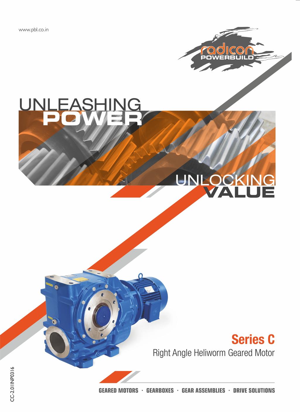
4 Series C right angle helical worm geared motors and reducers provide a highly efficient and compact solution to meet most requirements up to 45 kw with maximum output torque capacity of 10,000Nm. Following a long line of power transmission products, this product adds to the growing family of new drives which has taken advantage of our many years of accumulated design expertise, together with the use of high quality materials and components. The end result is a series of speed reducing and geared motors offering high load carrying capacity, increased efficiency, quiet running and reliability. The Range Includes Eight sizes of units with a ratio coverage of 8:1 to 250:1 in double reduction and 16000:1 in combined units. Version W - Standard nit (C03 - C06 Only) Version B - Standard nit with Base ounted Feet Version E - Standard nit with End ounted Feet Version R - Standard nit with Top ounted Feet Version F/H - Standard nit with Flange Version G - Standard nit with Flange Reduced Diameter (size C03 only) Version T/Q - Standard nit with Torque Arm Version - Standard nit Torque Arm Heavy Duty (C10 only) nit Types: nit type - otorised with IEC Standard otor nit type G - nit to Allow Fitting of Customers IEC otor nit type R - Reducer nit nit type S - Reducer nit with Fan Kit nit type W - Reducer nit with Backstop CCW Rotation nit type X - Reducer nit with Backstop CW Rotation nit type Y - Reducer nit with Fan and Backstop CW Rotation nit type Z - Reducer nit with Fan and Backstop CCW Rotation Design Features Include Patented standard motor connection (IEC or NEA). Ability to fit double oil seals input and output as required. All units are dimensionally interchangeable with other major manufacturers. Brake geared motors are available as standard. s 03, 04, 05 and 06 are lubricated for life. otorised units can be fitted with a backstop module and reducer units can be fitted with a backstop and fan. nits are manufactured and assembled from a family of modular kits for distributor friendliness minimising inventory and maximising availability. GENERAL DESCRIPTION Two stage reduction unit with base mounted feet and hollow output shaft * C B R H Four stage motorised unit with end mounted feet and hollow output shaft * C E H - 1 A. 1 8 A - - Four stage reduction unit with hollow output shaft * C W R H Two stage motorised unit with output flange and single extension output shaft Four stage reduction unit with base mounted feet and hollow output shaft As improvements in design are being made continually this specification is not to be regarded as binding in detail and * drawings and capacities are subject to alteration without C B R H notice. Certified drawings will be sent on request. Two stage reduction unit with output flange and single extension output shaft * C F R C * Typical unit designations 2
5 * Example 1 - Series C Range C 2, 3 - of nit C Through No of Reductions Revision Version 1 For s 03 to 10 6,7,8 - Nominal Overall Ration eg Gear codes otor codes C B C - 1 D. 1 8 A - - No of otor Features 18 - No motor 50 Hz 60 Hz S Additional Gearbox Features Double Oil Seal, otorised Backstop Etc eg - F Additional otor Features eg - A For Types Without otor Enter 4 Pole (Std) 1500 rpm 1800 rpm A 4 Pole (High)1500 rpm 1800 rpm K 6 Pole (Std) 1000 rpm 1200 rpm C 6 Pole (High)1000 rpm 1200 rpm 2 Pole 3000 rpm 3600 rpm E 8 Pole 750 rpm 900 rpm G Dual Speed or Special otor - B L D N F H 9 - nit Version W B E - Standard nit (C03 - C06 Only) - Standard nit with Base ounted Feet - Standard nit with End ounted Feet R - Standard nit with Top ounted Feet Std nit with Flange F on Left H on Right G - Std nit with Flange Reduced Dia (C03 Only) Std nit withtorque Arm T on Left Q on Right - Std nit withtorque Arm - Heavy Duty (C10 Only) 15, 16, 17 - Geared otor Powers otor Power Required ounting Position 13, 14 - eg 2 B 12 - eg 7 5 For Reducer or Non-Standard. otor Types Enter otor Adaptor For nit Types Column 10 Entries, N, H, E, G or A For All Other Types Enter Type of nit - otorized with IEC standard motor G - nit to allow fitting of IEC motor (customer own motor) R - Reducer unit S - Reducer unit with fan kit W - Reducer unit with backstop CCW rotation X - Reducer unit with backstop CW rotation Y - Reducer unit with fan and backstop CW rotation Z - Reducer unit with fan and backstop CCW rotation 11 - Shaft Standard Single Extension C on Left E on Right Standard Double Extension D Standard Hollow Shaft H nit with Hollow Shaft with Reduced Bore Dia Z Heavy Duty Single Extension ( C06) J Heavy Duty Double Extension ( C06) K * This page may be photocopied allowing the Customer to enter their order 3
6 Gear unit selection is made by comparing actual loads with catalogue ratings. Catalogue ratings are based on a standard set of loading conditions, whereas actual load conditions vary according to type of application. Service Factors are therefore used to calculate an equivalent load to compare with catalogue ratings. i.e. Equivalent Load = Actual Load x Service Factor echanical ratings and service factor Fm EXPLANATION & SE OF RATINGS & SERVICE FACTORS echanical ratings measure capacity in terms of life and/or strength, assuming 10 hr/day continuous running under uniform load conditions. Catalogue ratings allow 100% overload at starting, braking or momentarily during operation up to 10 hours per day. The unit selected must therefore have a catalogue rating at least equal to half maximum overload. echanical Service Factor Fm (Table 1) is used to modify the actual load according to daily operating time, and type of loading. Load characteristics for a wide range of applications are detailed in Table 3 opposite, which are used in deciding the appropriate Service Factor Fm from Table 1. If overloads can be calculated, or accurately assessed, actual loads should be used instead of Fm. For units subjected to frequent stop/starts overloads in excess of 10 times/day multiply factor Fm x Factor Fs (table 2). Table 1. echanical Service Factor (Fm) Prime over Electric otor, Steam Turbine, or Hydraulic otor ulti-cylinder internal combusion engine single cylinder internal combustion engine Duration of service hrs Per day niform mass acceleration factor < 0.2 Load classification- driiven machine oderate mass acceleration factor < 0.3 Heavy acceleration factor< 10 < > < > < > ass acceleration factor = all external moments of inertia * moment of inertia of driving motor * calculated with reference to the motor speed Table 2. Number of Starts Factor (Fs) Starts/ stops per hour < > 200 Factor FS Note: (1) Intermediate values are obtained by linear interpolation Thermal Rating (For In-line Reducers) The Thermal Rating is the gearboxes ability to dissipate heat. If exceeded, may cause the lubricant to break down resulting in premature gear failure. A thermal check should be made in accordance with the Thermal Rating Proceedure 4
7 LOAD CLASSIFICATION BY APPLICATION Load Classifications - =niform Load =oderate Shock Load H =Heavy Shock Load =Consult our Engineers Agitators Pure liquids Liquids and solids Liquids variable density Blowers Centrifugal Lobe Vane Brewing & distilling Bottling machinery Brew Kettles Cookers ash tubs Scale hopper Can filling machinery Crane knife Car dumper Car puller Clarifier Classifier Clay wokring machinery Brick press Briquette machine Clay working machinery Plug mill Compressors Centrifugal Lobe Reciprocating ulti cylinder Single cylinder Conveyors- Light duty uniform load Apron Assembly Belt Bucket Chain Flight Oven Screw Conveyors - Heavy duty uniform load Apron Assembly Belt Bucket Chain Flight Live roll Oven Reciprocating Screw Shaker Cranes Crusher Ore Stone Sugar Dredger Cable reals Conveyors Cutter head drive Pumps Screen drive Stackers Winches H H H H H H H H Elevators Bucket - niform load Bucket - Heavy load Bucket - Continuous Centrifugal discharge Escalators Freight Gravity discharge Passenger lifts Fans Centrifugal Cooling towers Induced draft Forced draft Fan - Large diameter induced draft Fan - Light, small diameter Feeders Apron Belt Disc Reciprocating Screw Food industry Cereal cooker Dough mixer eat grinder eat slicer Generators - not welding Hammer mills Hoists Heavy duty edium duty Skip hoist Laundry Tumbler Washer Line shafts Heavy duty Light duty Lumber industry Barkers Burner conveyor Chain/ Drag saw Chain transfer Chain way transfer De- barking drum Edger feed Gang feed Green chain Live roll Log deck Log haul Log turning Log converyor Of bearing roll Planer feed chaines Planer hoist Re-saw conveyor Roll cases Slab conveyor Sorting table - triple hoist Triple hoist - Drive /conveyor Transfer converor Transfer roll Tray drive Trimmer feed Waster conveyor Small waste conveyor (belt) Small waste conveyor (chain) H H H H H H H H H H H H H H H achine Tools Bending roll Punch press Notching press Plate planer Other machine tools ain drive Aux drive etal mills Carriage/main drive Draw bench Dryer Flattening machinery Pinch drive Reversing slitters Scrubber rolls Table conveyors Group drives Individual drives Table conveyors- reversing Wire draw Wire roll ills Cement kiln Dryer, Cooler Kiln (other) Rod plain Rod wedge bar Rotary/ Ball Tumbling barrel ixers Concrete Cons density Variable density Oil industry Chiller s Oil well pump Filter press Rotary kiln Paper industry Agitator (mixer) Barker (hydraulic) Barker (mechanical) Barking drum Beater & Pulper Bleacher Calednders Calenders- super Converting machine Conveyors Couch Cutters - plates Cylinders Dryers Felt stretcher Felt whipper Jordans Log haul achine real Presses Stock chest Suction roll Washers & thickeners Winders Printing presses Pullers Barge haul HH H H H H H H H H H H H H H H H H H H Pumps Centrifugal proportioning Proportioning Reciprocating Single acting 3+ cylinders Double acting 2+ cylinders Single acting 1 & 2 cylinders Double acting 1 cylinder Rotary- gear type Rotary- lobe type/ vane Sand muller Sewage treatment Bar screen Chemical feeder Collector Dewatering screw ixers Scum breaker Thickness Vacuum filters Screens Air washing Rotary, stone or gravel Traveling water intake Slab pushers Slewing Steering gear Stokers Sugar industry Can knife Crusher ills Textile industry Batchers Calenders Cards Dry cans Dryers Dyeing machinery Knitting machinery Looms angles Nappers Pads Range drive Slashers Soapers Spinners Tenter frame Washers Winders Windlass H 5
8 SELECTION PROCEDRE FOR OTORISED NITS EXAPLE APPLICATION DETAILS Absorbed power of driven machine = 0.7 kw speed of gearbox or Input speed of machine = 68 rev/min Application = niformly loaded belt conveyor Duration of service (hours per day) = 24hrs ounting position = 1 Ambient temperature = 20ºC Running time (%) = 100% Note! If you select a Series C Reducer for use without TEFC motor, A thermal check must be made. 1 DETERINE ECHANICAL SERVICE FACTOR (Fm) Refer to Load Classification by Application, table 3, page 6 Application = niformly loaded belt conveyor Conveyors-uniformly loaded or fed apron assembly = niform load belt bucket chain Refer to mechanical service factor (Fm) Duration of service (hours per day) = 24hrs Prime mover Electric motor, steam turbine or hydraulic motor Duration of servicers per day Load classification niform nder < to Över > Therefore mechanical service factor (Fm) = 1.25 If the unit is subject to frequent start/stops Fm must be multiplied by factor Fs oderate 2 DETERINE REQIRED OTPT TORQE AT GEARBOX OTPTSHAFT Absorbed = Absorbed power x 9550 output torque Gearbox output speed 0.7 x 9550 = 98 Nm 68 3 SELECT GEARED OTOR Refer to selection table one motor size larger than absorbed power. Absorbed power = 0.7 kw, therefore refer to 0.75 kw selection table. Always select from 4 POLE selection table in the first instance as this offers a more economical solution. Required output speed of gearbox = 68 rev/min 0.75 kw N2 R/IN i 2 Nm Fm N NIT DESIGNATION Kg 4 POLE Spedd Ratio Torque Service Factor Overhung Load Column Entry 1 Through - 20 Spaces to be filled when entering order Weight of Base ount nit otor Frame C A A Go to point 4 6
9 4 CHECK OTPT TORQE torque (2) of selected unit must be equal or more than required output torque at gearbox outputshaft. Required output torque at gearbox outputshaft = 98 Nm kw 4 POLE N2 R/IN SPEED i Ratio 2 Nm Torque Fm Service Factor N Overhung Load Column Entry 1 Through 20 Spaces to be filled when entering order SELECTION PROCEDRE FOR OTORISED NITS NIT DESIGNATION C A A Kg Weight of Base ount nit otor Frame However the output torque is only 84 against the requirement of 98 Nm, hence a unit fitted with a 1.1 kw motor is required 1.1 kw N2 R/IN 4 POLE SPEED i Ratio 2 Nm Torque Fm Service Factor N Overhung Load Column Entry 1 Through C A S Selected unit s output torque (2) = 123 Nm, therefore the torque from a 1.1 kw motor is acceptable. NIT DESIGNATION Spaces to be filled when entering order Kg Weight of Base ount nit otor Frame 5 CHECK SERVICE FACTOR Service factor (Fm) of selected unit must be equal or more than required service factor. Required service factor of gearbox = kw N2 R/IN 4 POLE SPEED i Ratio 2 Nm Torque Fm Service Factor N Overhung Load Column Entry NIT DESIGNATION 1 Through 20 Spaces to be filled when entering order C A S C A S C C C Kg Weight of Base ount nit otor Frame The service factor (Fm) is only 0.82, therefore this unit is not acceptable.and a larger C0421 unit must be selected with a service factor (Fm) of CHECK OVERHNG LOADS If sprocket, gear, etc is mounted on the outputshaft then refer to Overhung Loads Procedure, and compare with allowable overhung load (N) of selected unit Allowable overhung load (N) must be equal or more than calculated overhung load (P) 1.1 kw N2 R/IN 4 POLE Speed i Ratio 2 Nm Torque Fm Service Factor N Overhung Load Column Entry NIT DESIGNATION 1 Through 20 Spaces to be filled when entering order C A S Kg Weight of Base ount nit otor Frame NOTE: If any of the following conditions occur then consult our Application Engineers:- a) Inertia of the Driven achine (Referred to motor speed) >10 b) Ambient temperature is above 40ºC Inertia of Gear nit plus the otor 7
10 OTPT OPTIONS OTPTSHAFT OPTIONS, COLN 11 ENTRY L11 L12 t Column 11 Entry Standard Single Extension C on Left E on Right Standard Double Extension D w L u Od Std Heavy Duty Single Extension ( C06) Std Heavy Duty Double Extension ( C06) J K Type of Shaft Column 11 Entry Dimensions in mm ød L L11 L12 t u w C03 etric - Standard C, E, D / x 1.0 x 16 C04 etric - Standard C, E,D / x 1.5 x 22 C05 etric - Standard C, E, D / x 1.5 x 22 C06 etric - Standard C, E, D / x 1.75 x 22 etric - Heavy Duty J, K / x 2.0 x 36 C07 etric - Standard C, E, D / x 2.0 x 36 C08 etric - Standard C, E, D / x 2.5 x 42 C09 etric - Standard C, E, D / x 2.5 x 42 C10 etric - Standard C, E, D / x 3.0 x 50 8
11 OTPTBORE OPTIONS OTPT BORE OPTIONS, COLN 11 ENTRY Column 11 Entry etric Hollow Shaft H m1 m2 v3 etric Hollow Shaft with reduced bore diameter Z OD Om3 T m m Type of Bore Column 11 Entry Dimensions in mm ød m m1 m2 øm3 T v3 C03 Standard H / x 1.0 x 40 C04 C05 C06 C07 C08 C09 C10 Standard H / x 1.5 x 50 Reduced Dia Z / x 1.5 x 50 Standard H / x 1.75 x 55 Reduced Dia Z / x 1.5 x 45 Standard H / x 2.0 x 70 Reduced Dia Z / x 2.0 x 70 Standard H / x 2.5 x 80 Reduced Dia Z / x 2.0, x 70 Standard H / x 2.5 x 80 Reduced Dia Z / x 2.5 x 80 Standard H / x 3.0 x 110 Reduced Dia Z / x 2.5, x100 Standard H / x 3.0 x 110 Reduced Dia Z / x 2.5 x 100 9
12 Double Reduction nits OTOR ADAPTERS IEC Integral otor - Column 19 Entry - I C0321 C0421 C0521 C0621 C0721 C0821 Power kw kw kw kw kw kw kw kw kw kw kw Standard otor IEC Flanges B14 - Column 12 Entry C0321 C0421 C0521 C0621 C0721 otor H H H H - H B K B K B K - G - G 90 D R D R D R Z J - J 100 E S E S E S B L B L 112 E S E S E S B L B L D N Standard otor IEC Flanges B5 - Column 12 Entry C0321 C0421 C0521 C0621 C0721 C0821 C0921 C1021 otor F F F F - F - V G G G G - G - D A J A J A J W F - F - D - E C Q C Q C Q Y H - H - E - F A K A K A F - G - E A K A K A F - G - E N P C B G - H - F E P C H A J A G B K B H C L C J D D K
13 Triple Reduction nits OTOR ADAPTERS IEC Integral otor - Column 19 Entry - I C0331 C0431 C0531 C0631 C0731 Power kw kw kw kw kw kw kw kw kw kw kw Standard otor IEC Flanges B14 - Column 12 Entry C0331 C0431 C0531 C0631 C0731 otor H H H H H H - H B K B K B K B K - G 90 D R D R D R D R Z J 100 E S E S E S E S B L B L Standard otor IEC Flanges B5 - Column 12 Entry C0331 C0431 C0531 C0631 C0731 otor F F F F F F - F - V 71 G G G G G G - G - D 80 A J A J A J A J W F 90 C Q C Q C Q C Q Y H A K A K N P 11
14 Quadruple Reduction nits OTOR ADAPTERS IEC Integral otor - Column 19 Entry - I C0341 C0441 C0541 C0641 C0741 C0841 C0941 C1041 Power All Ratios All Ratios All Ratios All Ratios All Ratios 0.25 kw kw kw kw kw kw kw kw kw kw kw Standard otor IEC Flanges B14 - Column 12 Entry C0341 C0441 C0541 C0641 C0741 C0841 C0941 C1041 otor All Ratios All Ratios All Ratios All Ratios All Ratios 71 H H H H H K K K K K - G - G - G 90 R R R R R Z J Z J - J 100 S S S S S B L B L B L B L B L B L D N Standard otor IEC Flanges B5 - Column 12 Entry C0341 C0441 C0541 C0641 C0741 C0841 C0941 C1041 otor All Ratios All Ratios All Ratios All Ratios All Ratios 63 F F F F F - V - V G G G G G - D - D J J J J J W F W F - F 90 Q Q Q Q Q Y H Y H - H A K A K A K A K A K K K N P N P C E
15 LBRICATION Lubricant and Quantity nit sizes C03, 04, 05 and 06 are factory filled with a grade 7G lubricant. nit sizes C07, 08, 09 and 10 will be despatched without oil. The oil grade is stamped on the name plate and the oil level should be established by filling until the oil escapes via the level plug, The grade and level are determined from the operating speed of the gear unit and the ambient temperature range, which if not given when ordering will be assumed to be 1450 rev / min input and ambient temperature range 20 to 50ºC. Oil grades and oil level should always be checked before installation, Consult the Installation and aintenance instructions provided with the gear unit. To determine the oil grade refer to table 1, and then refer to the Installation and aintenance istructions to select an approved lubricant To determine the oil capacity refer to appropriate table 2 or 3. Oil capacities are only approximate and units should be filled until oil escapes from the level plug holes. Do not overfill as excess will cause overheating and leakage. Always fill with correct lubricant as marked on the nameplate. Never mix lubricant grades. See Installation and aintenance instructions for for lists of approved lubricants within the grades ºC - 20ºC 0ºC - 35ºC 20ºC - 50ºC G 6G 8G 0> G 6G 7G > G 6G 6G G 6G 8G > G 6G 7G G 6G 8G < G 7G 9G > G 6G 8G G 7G 9G * For other ambient temperatures please refer to our Application Engineers. 1 If not stated with the order these are the operating conditions that will be assumed Table 1 Series C oil grades Gear unit details Type Ratio Input Speed (Rev/min) Note: Catalogue ratings are based on Polyglycol Synthetic lubricant se with mineral or alternative lubricants may require a derate, please contact our Application Engineers. Table 2 lubricant quantity (Litres) (double reduction and final stage quadruple reduction) ounting position Doubles Quadruples Level Level Double, Triple & Final stage Quadruple Reduction C0321 C0331 C0421 C0431 C0521 C0531 C0621 C0631 C0721 C0731 C0821 C0921 C * * Level 1 * Level 2 * Level 1 * Level 2 * * se Level 1 for output speeds lower than 100 rpm * se Level 2 for output speeds of 100 rpm and higher. Table 3 lubricant quantity (Litres) (primary stage quadruple reduction) Ambient temperature range Primary stage quadruple reduction C0341 C0441 C0541 C0641 C0741 C0841 C0941 C1041 Secondary unit (Lubricant quantity see table 2) C0321 C0421 C0521 C0621 C0721 C0821 C0921 C1021 Primary unit Primary Quantitty 1 to (unit lubricant) 5 & nit filled with Grade 7G lubricant suitable for all ambient temperatures between 20ºC to 50ºC and are lubricated for life 13
16 ONTING POSITIONS 6 * Colum 13 Entry 1 2 * ounting Position 6 is not recommended for geared motors - Consult Application Engineering 5 Gear nits for use in mounting positions 5 and 6 3 Base ounted nits should only be selected with overall ratios greater or equal to those shown in table below 4 Input speed (RP) >1800 C03-C08 All All All C09 18:1 18:1 25:1 C10 18:1 40:1 63:1 Consult application engineering 6 * Flange ounted nits 4 ounting Positions- Shown as otorised - Applies also for Reducers 270 o Column 14 entry Terminal box position COLN 14 ENTRY A 0º All motors B 90º C 180º D 270º 0o 180 o 90 o 14 Reducer or no motor fitted
17 NIT HANDINGS Column 9 entry Entry Left Right Std nit with Flange Std unit with foutput flange F H Std nit with Torque Bracket Std unit with Torque bracket T Q Column 11 entry 11 Entry Left etric Right Left Inch Right Single output shaft Shaft C E N B Double output shaft Shaft D P Hollow Shaft Hollow shaft H A 15
18 NOTES 16
19 OTORISED 17
20 18 NOTE
21 OTOR DETAILS B14 'C' face k0* g1* m g6 Ø m Ø n Ø d Ø k0 * g Ø g1 e m Øs g6 m n d g øg6 øm øn ød e ko øg g1 m øs e Øs 45 deg 4x deg 4x6 90S deg 4x8 90L deg 4x8 100L deg 4x deg 4x8 k0 g1 g6 Ø m Ø Ø n Ø Ø Ø d Ø Ø Ø B5 'D' face k0* g Ø m g1* g6 Ø m Ø n Ø d Ø e * g Ø m Ø s e Ø s øg6 øm øn ød e ko øg g1 m øs deg 4x deg 4x deg 4x12 90S deg 4x12 90L deg 4x12 100L deg 4x deg 4x15 132S deg 4x deg 4x deg 4x19 160L deg 4x deg 4x19 180L deg 4x19 200L deg 4x19 225S deg 8x deg 8x deg 8x24 280S deg 8x deg 8x24 315S deg 8x deg 8x24 315L deg 8x24 * Diamension for own brand standard motors. These may vary if alternative motor is fitted. 19
22 ADDITIONAL OTOR FEATRES RADICON POWERBILD motor features - Column 19 Entry Brake oter (with RL) (Consult PBL Design for Detail) (Consult PBL Design for Detail) (Other than above) 20
23 ADDITIONAL GEARBOX FEATRES Additional Gearbox Features- Column 20 Entry Colum 20 entry Double Oil Seals on Shaft CW Rotation * otorised Backstop CCW Rotation Special - A D E H I L Please refer to our Application Engineers for details of the following additional gearbox features - Prime paint only - Wash down - BISSC compatible - Special oil (food compatible, bio-degradable, different viscosities etc) * IEC B5 frame sizes
24 SELECTION TABLE GEARED OTORS 0.12 kw 4 POLE N2 RP Speed i Ratio 2 Nm Torque Fm N nit Designation kg Service Factor Overhung Load Column Entry 1-20 Spaces to be filled when entering order Weight of Base ount unit C A otor C A C A C A C A NOTE: Other output speeds are available using 2 & 8 pole motors. Please contact our Application Engineers C A C A
25 SELECTION TABLE GEARED OTORS 0.12 kw 4 POLE N2 RP Speed i Ratio 2 Nm Torque Fm N nit Designation kg Service Factor Overhung Load Column Entry 1-20 Spaces to be filled when entering order Weight of Base ount unit C C A C C C C A otor C C A C C C C C C C C C C A C C C C C C C C C C 0.12 kw 6 POLE NOTE: Other output speeds are available using 2 & 8 pole motors. Please contact our Application Engineers C C A C C C C C C C C C C C C
26 SELECTION TABLE GEARED OTORS 012.kW 6 POLE N2 RP Speed i Ratio 2 Nm Torque Fm N nit Designation kg Service Factor Overhung Load Column Entry 1-20 Spaces to be filled when entering order Weight of Base ount unit C C otor C C C C C C C C C C C C C C C C C C C NOTE: Other output speeds are available using 2 & 8 pole motors. Please contact our Application Engineers C C C C C C C C C C C C C 24
27 SELECTION TABLE GEARED OTORS 012.kW 6 POLE 0.18 kw 4 POLE N2 RP Speed i Ratio 2 Nm Torque Fm N nit Designation kg Service Factor Overhung Load Column Entry 1-20 Spaces to be filled when entering order Weight of Base ount unit C C C C C C C C C C C C C C C C A otor C A C A NOTE: Other output speeds are available using 2 & 8 pole motors. Please contact our Application Engineers C A C A
28 SELECTION TABLE GEARED OTORS 0.18 kw 4 POLE N2 RP Speed i Ratio 2 Nm Torque Fm N nit Designation kg Service Factor Overhung Load Column Entry 1-20 Spaces to be filled when entering order Weight of Base ount unit C A otor C A C A C A C C A C C C C C C A C C C C C C C C C C C C NOTE: C C A C C C C C C C C C Other output speeds are available using 2 & 8 pole motors. Please contact our Application Engineers 26
29 SELECTION TABLE GEARED OTORS 0.18 kw 6 POLE N2 RP Speed i Ratio 2 Nm Torque Fm N nit Designation kg Service Factor Overhung Load Column Entry 1-20 Spaces to be filled when entering order Weight of Base ount unit C C otor C C C C C C C C NOTE: Other output speeds are available using 2 & 8 pole motors. Please contact our Application Engineers C C C C C C
30 SELECTION TABLE GEARED OTORS 0.18 kw 6 POLE N2 RP Speed i Ratio 2 Nm Torque Fm N nit Designation kg Service Factor Overhung Load Column Entry 1-20 Spaces to be filled when entering order Weight of Base ount unit C C C C otor C C C C C C C C C C C C C C C C 0.25 kw 4 POLE NOTE: Other output speeds are available using 2 & 8 pole motors. Please contact our Application Engineers C C C C C C C C C C C C C C C A C A
31 SELECTION TABLE GEARED OTORS 0.25 kw 4 POLE N2 RP Speed i Ratio 2 Nm Torque Fm N nit Designation kg Service Factor Overhung Load Column Entry 1-20 Spaces to be filled when entering order Weight of Base ount unit C A otor C A C A C A C A C A NOTE: Other output speeds are available using 2 & 8 pole motors. Please contact our Application Engineers C A C C A C C C A C C C C 29
Series C Helical Worm
 Series C Helical Worm Technical p to - 45 Kw / 10,000 Nm Geared otors CC-2.01GB0914 PRODCTS IN THE RANGE Series A Worm Gear units and geared motors in single & double reduction types Series BD Screwjack
Series F Shaft Mounted Helical
 Series F Shaft ounted Helical Technical Up to - 110 kw / 16,500 Nm Geared otors CF-2.01GB1 ATEX Compliance Assured Total compliance with the ATEX Directive safeguarding the use of industrial equipment
Series P Planetary. Technical Up to - 90kW / 65000Nm. Planetary CP-2.00GB0 1
 VARIMAX AG, Antriebstechnik, Normannenstrasse 14, Postfach 762, CH-3018 Bern Tel. +41 (0)31 990 00 70 e-mail info@varimax.ch Fax +41 (0)31 990 00 71 web www.varimax.ch Series P Planetary Technical Up to
Series C Helical Worm
 Series C elical Worm Technical p to - 60 P / 89,000 lb.in Geared otors CC- S03 8 PRODCTS IN TE RANGE Serving an entire spectrum of mechanical drive applications from food, energy, mining and metal; to
Size 1120, Bore Ø0.75" Size 1320, Bore Ø1.25" Size 1420, Bore Ø1.375" 3/4HP. Size 1320, Bore Ø1.25" Size 1320, Bore Ø1.25" Size 1633, Bore Ø2.
 Product Range Hollow Shaft Type Selections shaded in blue offer an increased service factor. Please refer to the gearmotor selection tables for specific unit service factor details. Nominal Ratio (:1)
Series F Shaft Mounted Geared Motor- Version 3
 Series F Shaft ounted Geared otor- Version 3 Technical p to - 45kW/ 8000 Nm Geared otor CF3.01-GBD-0 18 PRODCTS IN TE RANGE Series A Worm Gear units and geared motors in single & double reduction types
Speed Reducers and Gearmotors
 and Gearmotors Table of Contents 1. General Information 2. How to Select...2.2 Configure a Model Number (Nomenclature)...2.4 AGMA Load Classifications...2.6...2.8 Single Reduction,,, Y3, Y5,...2.8 Single
Series F Shaft Mounted Helical
 Series F Shaft ounted elical Technical p to - 150 P / 146,000 lb.in Geared otors CF- S 11 PRODCTS IN TE RANGE Serving an entire spectrum of mechanical drive applications from food, energy, mining and metal;
Cyclo Speed Reducers CATALOG
 Cyclo 6000 CATALOG 03.601.50.005 Cyclo 6000 Superior design, powerful performance The Cyclo 6000 is also available as an inline Gearmotor To request a catalog, or for more information on any of our high
CYCLO 6000 Gearmotors. How to Select. How to. Select. Cyclo 6000 Series. How to Select 2.1
 2 How to Select How to Select Cyclo 6000 Series How to Select 2.1 How to Select a Gearmotor Step 1: Step 2: Collect data about your application Before starting you need to know the: (e.g. Conveyor, Mixer,
Gear Coupling. Applications
 Gear Coupling Applications Power Transformation Print & Paper Industries Gear Boxes Textile Industries Conveyors Pumps Compressors Process, Chemical & Pharmaceutical Industries Nylon Gear Couplings Nylon
Catalog April Metric Motorized Torque-Arm II Technical catalog
 Catalog April 2015 Metric Motorized Torque-Arm II Technical catalog With expertise, and a comprehensive portfolio of products and life-cycle services, we help value-minded industrial customers improve
Power Transmission Products. Maurey Couplings. Hi-Flex Tire Couplings Hi-Q Jaw Couplings Finished Bore Sleeve Couplings Rigid Bushed Sleeve Couplings
 Power Transmission Products Maurey Couplings Hi-Flex Tire Couplings Hi-Q Jaw Couplings Finished Bore Sleeve Couplings Rigid Bushed Sleeve Couplings Hi-Q Flexible Couplings R to enable full power transmission
Hyponic. Hypoid Right Angle Gearmotor and Reducer CATALOG
 Hypoid Right Angle Gearmotor and Reducer CATALOG 12.001.50.005 Hypoid Right Angle Patented, High-Performance Gearmotors and Reducers Featuring All-Steel Hypoid Gearing U. S. PAT. NO. 5,203,231; U.S. PAT.
Section 9: Gearboxes: Series K
 GEARBOXES Section : 9 Section 9: Gearboxes: Series K The Fenner Series K incorporates all the core design features in a highly efficient yet flexible bevel helical drive. Drives up to 90 Highly efficient
Speed Reducers. Speed Reducers. Speed Reducers. How to. Select. Cyclo HBB. Speed Reducers 2.1
 2 How to Select 2.1 How to select a Reducer Step 1: Step 2: Step 3: Collect data about your application Before starting you need to know the: Application (e.g. Conveyor, Mixer, etc.) Hours of Operation
CONTENTS MAXUM Concentric Reducers
 CONTENTS s Features/Benefits.............................................. G3-2 Specifications................................................. G3-4 How to Order.................................................
Falk Ultramite UC Helical Concentric Gear Drives
 Gear Catalog Download the most up-to-date versions at www.rexnord.com Falk Ultramite UC Helical Concentric Gear s (Inch) Falk Ultramite UC Helical Concentric Gear To learn more about the Falk Ultramite
Section 9: Gearboxes: Series F
 GEARBOXES Section 9: Gearboxes: Series F The new Fenner Series F geared motor range is primarily designed as a compact shaft mounted unit incorporating an integral torque reaction bracket. ew range now
Flange Flexible Couplings.
 Flange Flexible Couplings Coupling Selection Coupling Selection How to Select Standard Selection The Standard Selection may be used for engine driven, motor, or turbine applications. The following information
Universal Joints. In This Section: D Type HD Type D Type Stainless NB (Needle Bearing) Type LOJ Type DD and DDX Type Universal Joint Boots
 Type LOJ Type DD and DDX Type Universal Joint Boots") JW Universal Joints In This Section: D Type HD Type D Type Stainless NB (Needle Bearing) Type LOJ Type DD and DDX Type Universal Joint Boots www.lovejoy-inc.com 329-1 JW Universal Joints Safety Warning
JW Universal Joints In This Section: D Type HD Type D Type Stainless NB (Needle Bearing) Type LOJ Type DD and DDX Type Universal Joint Boots www.lovejoy-inc.com 329-1 JW Universal Joints Safety Warning
RXC. traction drives. When an ordinary drive falls short... Featuring an all metal power train and optional advanced electronic control capabilities
 RXC traction drives Featuring an all metal power train and optional advanced electronic control capabilities When an ordinary drive falls short... Ring Cone Adjustable Speed Traction Drives Control Ring
Maxum XTR Concentric reducers catalog
 MECHANICAL POWER TRANSMISSION Maxum XTR Concentric reducers catalog Maxum XTR Concentric reducers catalog To receive a copy of the Dodge Maxum XTR Catalog, Dodge Bearing Engineering Catalog, Dodge Gearing
SPECIFICATION HOW TO ORDER QUANTIS QUANTIS
 The DODGE speed reducer is suitable for c-face, separate, or integral gearmotor construction in either foot or output flange mountings, and available in single, double or triple ratios. The DODGE RHB and
Catalog. MagnaGear XTR gear reducers Gearing
 Catalog MagnaGear XTR gear reducers Gearing We provide motors, generators and mechanical power transmission products, services and expertise to improve customers' processes and optimize the total cost
HELICAL AND BEVEL-HELICAL UNITS
 I V-I IS S I W I QS I IS ISI V-I IS ISI II SII, KY SYS IIY I SVI SSIII IY SI S I SIS I SIS I SIS I SIS /V V-I SIS /V V-I SIS /V V-I SIS SIS /V SIS SIS SIS SIS SIS SIS V SIS SIS V SIS SIS V SIS S S I SIIS
Specialty Couplings. Overview. Deltaflex Coupling Design Lovejoy offers maximum misalignment capacity with the Deltaflex coupling! SP-3.
 Overview Deltaflex Coupling Design Lovejoy offers maximum misalignment capacity with the Deltaflex coupling! The Deltaflex coupling is the real solution to installation, misalignment, and performance problems.
Speed Reducers and Gearmotors featuring Keyless Taper-Grip Bushing
 Cyclo BBB BEVEL BUDDYBOX Speed Reducers and Gearmotors featuring Keyless Taper-Grip Bushing CATALOG 13.601.50.006 Cyclo BBB Bevel Buddybox Rugged Spiral Bevel Output Modular Cyclo Input Compact Size Ring
Falk Type YB & GHB Horizontal Right Angle Gear Drives
 Falk Series YB & GHB Gear Drives Proven Performance for Thermal Capacity Applications (English Inch) Falk Type YB & GHB Horizontal Right Angle Gear Drives Since 1897, Falk gear drives have benefitted from
Falk Series Y & YF Gear Drives. Proven Performance for High Thermal Capacity Applications (English Inch)
") Falk Series Y & YF Gear Drives Proven Performance for High Thermal Capacity Applications (English Inch) Falk Series Y&YFParallel Gear Drives Since 1897, Falk gear drives have benefitted from specialized
Falk Series Y & YF Gear Drives Proven Performance for High Thermal Capacity Applications (English Inch) Falk Series Y&YFParallel Gear Drives Since 1897, Falk gear drives have benefitted from specialized
SERIES B INDUSTRIAL DUTY GEARMOTORS & REDUCERS
 Series B 0207 INDSTRIAL DTY GEAROTORS & REDCERS The Series B right angle gearmotors and reducers provide a highly flexible and compact solution to meet the low to medium power range. With power capabilities
Cyclo BBBBEVEL BUDDYBOX
 Cyclo BBBBEVEL BUDDYBOX Speed Reducers and Gearmotors featuring Keyless Taper-Grip Bushing CATALOG 13.601.50.003 Cyclo BBB BEVEL BUDDYBOX Speed Reducers and Gearmotors featuring Keyless Taper-Grip Bushing
SERIES B POWER TRANSMISSION SOLUTIONS
 SERIES B POWER TRANSISSION SOLTIONS PRODCTS IN TE RANGE Serving an entire spectrum of mechanical drive applications from food, energy, mining and metal; to automotive, aerospace and marine propulsion,
Section 9: Gearboxes: Series W
 GEARBOXES Section : 9 Section 9: Gearboxes: Series W A modular designed aluminium worm box available in a vast range of sizes and ratios for cost effective solutions. 9 s with ratings from 0.09 to 7.5kW
Hyponic. Hypoid Right Angle Gearmotor and Reducer CATALOG
 Hypoid Right Angle Gearmotor and Reducer CATALOG 12.001.50.007 Hypoid Right Angle Patented, High-Performance Gearmotors and Reducers Featuring All-Steel Hypoid Gearing U. S. PAT. NO. 5,203,231; U.S. PAT.
FLEXIBLE JAW COUPLINGS
 To order this part, call Lifco Hydraulics USA Toll Free at -800-92-849 Jaw Type Couplings USA Standard The Jaw Type Couplings from Vescor are offered in the industry s largest variety of stock bore/keyway
MASTER ENGINEERING/ TECHNICAL. XL Reducers And Gearmotors INSTALLATION
 INSTALLATION Proper installation of MASTER speed reducers will ensure reliable service and maximum life. Key items to minimize possible failures include: Gear Case Mounting To insure uniform pressure mount
LMI Product Catalog. Premium Shaft Mount Gear Reducers Built For The Long Haul
 LMI Product Catalog Premium Shaft Mount Gear Reducers Built For The Long Haul Featuring Shaft Mount Models DIR1 through DIR10, Accessories, and Rebuild Kits The Better Alternative! January 2004 LMI Shaft
SERIES B POWER TRANSMISSION SOLUTIONS
 POWER TRANSISSION SOLTIONS PRODCTS IN TE RANGE Serving an entire spectrum of mechanical drive applications from food, energy, mining and metal; to automotive, aerospace and marine propulsion, we are here
Thomas Flexible Disc Couplings (Inch)
") Disc Catalog Download the most up-to-date version at www.rexnord.com/documentation Thomas Flexible Disc s (Inch) Table Of Contents DESCRIPTION PAGE Application Guide................................................................................................................
Disc Catalog Download the most up-to-date version at www.rexnord.com/documentation Thomas Flexible Disc s (Inch) Table Of Contents DESCRIPTION PAGE Application Guide................................................................................................................
FALK ULTRAMITE Delivers Local Availability, NEMA/IEC Compatibility Plus Drop-in Replacement
 Falk Ultramite UB Right-Angle Gear Drive Delivering The Right Punch for Productivity (English-Inch) FALK ULTRAMITE Delivers Local Availability, NEMA/IEC Compatibility Plus Drop-in Replacement It s a winning
Series X Flexible Couplings
 Series X Flexible Couplings Flexible Couplings CX-3.00GB0713 PRODCTS IN T RANG Serving an entire spectrum of mechanical rive applications from foo, energy, mining an metal; to automotive, aerospace an
Section 9: Gearboxes: Series C
 GERBOXES Section 9: Gearboxes: Series C Modern design techniques enable the Fenner Series C Helical Worm gear unit to out perform any other gearbox in terms of lowest cost /. Drives up to 45kW Energy efficient
ER Worm Gears. Worm Gears CER-2.01GB0415
 ER Worm Gears Worm Gears CER-2.01GB0415 PRODCTS IN TE RANGE Serving an entire spectrum of mechanical drive applications from food, energy, mining and metal; to automotive, aerospace and marine propulsion,
FALK ULTRAMITE Delivers Local Availability, NEMA/IEC Compatibility Plus Drop-in Replacement
 Falk Ultramite UJ Shaft-Mounted Offset Helical Gear Drive Delivering The Right Punch for Productivity (English-Inch) FALK ULTRAMITE Delivers Local Availability, NEMA/IEC Compatibility Plus Drop-in Replacement
Thomas Flexible Disc Couplings (Metric)
") Disc Catalog Download the most up-to-date version at www.rexnord.com/documentation Thomas Flexible Disc s (Metric) Table Of Contents DESCRIPTION PAGE Application Guide................................................................................................................
Disc Catalog Download the most up-to-date version at www.rexnord.com/documentation Thomas Flexible Disc s (Metric) Table Of Contents DESCRIPTION PAGE Application Guide................................................................................................................
Viking Helical Gear Reducers
 Page 610.1 Issue J Gear Ratio Range: (varies by reducer size) 1.87:1 to 7.95:1 Output Speeds (with 1750 rpm input) Reducer Horsepower Range: 950 to 220 rpm 1.4 HP (.1 kw) to 49.8 HP (37.2 kw) THREE SIZES
XL Right Angle and Parallel Reducers and Gearmotors
 CONTENTS XL Right Angle and Parallel Reducers and Gearmotors Contents Updated 11-7-2016 Features / Benefits XL Right Angle Reducers and Gearmotors...XL-2 XL Parallel Reducers and Gearmotors...XL-3 Specification
Disclosure to Promote the Right To Information
 इ टरन ट म नक Disclosure to Promote the Right To Information Whereas the Parliament of India has set out to provide a practical regime of right to information for citizens to secure access to information
V ariodrive units are available with standard NEMA motor flange as well as optional IEC motor flanges to fit your needs.
 Features and Benefits Ribbed aluminum housing* provides expanded surface area and greater heat dissipation than traditional cast iron housings. This allows for higher thermal capacity and reduced internal
The Strong Silent Type
 The Strong Silent Type Shaft Mount Speed Reducers SMR-15 Vortex Shaft Mount Reducers Engineering Guide VORTEX www.vortexreducer.com 2 Shaft Mount Speed Reducers What do you want to do? Understand an Engineering
Thomas Flexible Disc Couplings (Metric)
") Disc Catalog Download most up-to-date versions at www.rexnord.com Thomas Flexible Disc s (Metric) Table Of Contents DESCRIPTION PAGE Application Guide................................................................................................................
Disc Catalog Download most up-to-date versions at www.rexnord.com Thomas Flexible Disc s (Metric) Table Of Contents DESCRIPTION PAGE Application Guide................................................................................................................
Gearmotor Section... Page B-2-B-98
 GEARMOTORS Size -9 Range Gearmotor Section... Page B--B-98 Reducer Section... Page B-100-B-1 For Ratings < 7,600 In. Lbs. - See Catalog 3000-0 or www.emerson-ept.com B-1 FEATURES and BENEFITS GEARMOTORS
SURE-FLEX ELASTOMERIC COUPLINGS
 SECTION F1 SURE-FLEX ELASTOMERIC COUPLINGS Need No Lubrication, No Maintenance Quick, Easy Installation Clean, Quiet Performance TB WOOD S INCORPORATED Chambersburg, Pennsylvania 17201 T.B. WOOD S CANADA
HELIMAX. Parallel/Orthogonal Gear Units with Ground Helical Gear. Bipartite housing. Monobloc housing. 1 Stage
 HELIAX Parallel/Orthogonal Gear Units with Ground Helical Gear Bipartite housing onobloc housing 1 Stage www.wegcestari.com Index Description Page General characteristics 2 Product designation 3-5 Selection
Series G Industrial Reducers
 Series G Industrial Reducers Technical p to -,860kW / 65,000 Nm Industrial Reducers CG-2.00GB3 PRODCTS IN TE RANGE Serving an entire spectrum of mechanical drive applications from food, energy, mining
Viking s helical gear reducers are available in three basic sizes, each size offering several gear ratios.
 PARTS & ACCESSORIES: SIZES A, B & C Section 610 Page 610.1 Issue L Gear Ratio Range: (varies by reducer size) 1.87:1 to 7.95:1 Output Speeds (with 1750 rpm input) 950 to 220 rpm Reducer Horsepower Range:
Jaw Type JW JW-1. Polígono Indutrial O Rebullón s/n Mos - España -
 -1 Overview Couplings USA Standard Elastomer-in-Compression The couplings from Lovejoy are offered in the industry s largest variety of stock bore/keyway combinations. These couplings require no lubrication
Jaw Type. Overview. Jaw Type Couplings USA Standard Elastomer-in-Compression
 -1 Overview Jaw Type Couplings USA Standard Elastomer-in-Compression The Jaw Type couplings from Lovejoy are offered in the industry s largest variety of stock bore/keyway combinations. These couplings
SURE-FLEX ELASTOMERIC COUPLINGS
 SECTION F1 SURE-FLEX ELASTOMERIC COUPLINGS Need No Lubrication, No Maintenance Quick, Easy Installation Clean, Quiet Performance TB WOOD S INCORPORATED Chambersburg, Pennsylvania 17201 T.B. WOOD S CANADA
INDEX SECTION : M GRID COUPLING SECTION : N GEAR COUPLING SECTION :OJAWCOUPLING
 INDEX PAGE # SECTION : M GRID COUPLING GRID COUPLING Selection Procedure M 1 Coupling Selection based on Equivalent hp Ratings M 2-3 Service Factor M 4 Grid Coupling Type T-10 M 5 Grid Coupling Type T-20
Series X Flexible Couplings
 Series X Flexible Couplings Flexible Couplings CX-3.00GB0613 PRODCTS IN T RANG Serving an entire spectrum of mechanical drive applications from food, energy, mining and metal; to automotive, aerospace
Mechanical. Flexible Couplings. Lowest Cost TOTAL Solution
 Mechanical FC Flexible Couplings Lowest Cost TOTAL Solution SECTION F1 SURE-FLEX ELASTOMERIC COUPLINGS Need No Lubrication, No Maintenance Quick, Easy Installation Clean, Quiet Performance TB WOOD S INCORPORATED
Advantages of Delroyd Worm Gearing
 Advantages of Delroyd Worm Gearing Compactness and High Ratio Reduction Single reduction worm gearing offers high ratio reduction with few moving parts in a close-coupled compact drive. The right angle
Jaw. In This Section:
 Jaw In This Section: L Type LC Type Al Type - Aluminum SS Type - Stainless RRS and RRSC Types - Spacer C and H Type - Medium / Heavy Duty RRC Type - Spacer www.lovejoy-inc.com 13-1 Jaw Safety Warning When
Sure-Flex Plus couplings are selected as component parts. 1. Determine SLEEVE material and type. Refer to pages 4 & 5
 Sure-Flex Plus 4-Way flexing action absorbs all types of shock, vibration and misalignment Torsional Sure-Flex Plus coupling sleeves have an exceptional ability to absorb torsional shock and dampen torsional
Description. General characteristics 2. Product Code 3-5. Selection of gear-unit 6-7. Service factors 8-9
 www.wegcestari.com Index Description Page General characteristics 2 Product Code 3-5 Selection of gear-unit 6-7 Service factors 8-9 Radial forces / Permissible Radial orce -12 Output- torque 13 echanical
A SERIES ELASTOMER COUPLINGS
 A Retaining ring with locking feature B Wrap-around elastomeric insert C Hubs (blank or bored) D Anti-corrosion treatment A B C C D Spacer Arrangement Shown Product Description A Series elastomer couplings
Series A Junior Worm Gear
 www.radicon.com Series A Junior Worm Gear Technical p to - 12kW / 950 Nm CAJ1.00GBD0111 PRODCTS IN TE RANGE Serving an entire spectrum of mechanical drive applications from food, energy, mining and metal;
Gearbox standard series Your industrial Gearboxes. Standard Industrial NH/NHK
 www.gamesagearbox.com Standard Industrial 1 Contents Gear Design and Construction 3 Service Factors 5 Example of Selection 7 Spur Gearboxes NH I 8 NH II, NHS II, NHZ I2 NH III, NHS III, NHZ II7 NH IV,
SERIES G PRODUCTS IN THE RANGE
 0205 PRODCTS IN TE RANGE Serving an entire spectrum of mechanical drive applications from food, energy, mining and metal; to automotive, aerospace and marine propulsion, We are here to make a positive
L-Jaw Elastomeric Couplings
 L-Jaw Elastomeric Couplings F3 100% interchangeable with industry standard 3 Insert materials available 3 Hub materials available Large selection of sizes P-1686-TBW 4/16... TB Wood s 888-829-6637 F3-1
Shaft Mounted Speed Reducer Selection
 GEARBOX SELECTION PROCEDURE (a) Service Factor From Table 1 select the service factor applicable to the drive. (b) Design Power Multiply the absorbed power (or motor power if absorbed power not known)
QUADRA-FLEX 4-Way Flexing
 QUADRA-FLEX 4-Way Flexing Quadra-flex FLEXIBLE COUPLINGS Stocked Nationwide In Sizes 3 Through 16 Styles J, S, B, and SC Spacers C-4 QUADRA-FLEX 4-Way Flexing Martin QUADRA-FLEX Couplings, Non Lubricated,
H E L I C A L G E A R U N I T S
 ELICAL GEAR NITS Index Description SPECS. 001 ARKETING DATA Date Sheet Page No. Ref. Number 1. Index 001 1 2. Design features 003 2 SELECTION Procedures & Examples 1. orizontal nits S004 3 2. Vertical
Series B 2 23 TM
 23293.0209 T PRODCTS IN TE RANGE Serving an entire spectrum of mechanical drive applications from food, energy, mining and metal; to automotive, aerospace and marine propulsion, we are here to make a positive
A L T R A I N D U S T R I A L M O T I O N Flexible Couplings
 A L T R A I N D U S T R I A L M O T I O N Flexible Couplings SECTION F1 SURE-FLEX ELASTOMERIC COUPLINGS Need No Lubrication, No Maintenance Quick, Easy Installation Clean, Quiet Performance TB WOOD S
Shaft Mounted Speed Reducer. Technical Catalogue
 Shaft Mounted Speed Reducer Technical Catalogue Where others fit, We perform Contents The Challenge SMSR stands tall amongst the crowd. Packed full of attention to detail, the Challenge SMSR delivers performance
INDEX 1.0 GENERAL INFORMATION 3.0 ELECTRIC MOTORS 2.0 SHAFT MOUNTED GEARMOTORS 2.11 GEARMOTOR RATING CHARTS SPEED REDUCERS RATING CHARTS...
 INDEX 1.0 GENERAL INFORMATION 2.11 GEARMOTOR RATING CHARTS 25 2.12 SPEED REDUCERS RATING CHARTS... 64 2.13 MOTOR AVAILABILITY... 84 2.14 MASS MOMENT OF INERTIA... 88 1.1 SYMBOLS AND UNITS... 2 1.2 TORQUE...
Viking In-Line Helical Gear Reducers
 Page 615.1 Gear Ratio Range: (varies by reducer size) Output Speeds (with 1750 rpm input) Reducer Horsepower Range: From 2.63:1 to 38.0:1 (Varies by reducer size) 46 665 rpm.5 HP (.37 kw) to 350 HP (261
Falk Steelflex Grid Couplings (Metric)
") Grid Coupling Catalog Download the most up-to-date versions at www.rexnord.com Falk Steelflex Grid Couplings (Metric) Table Of Contents DESCRIPTION PAGE Falk Steelflex Grid Coupling Application Guide...3
Grid Coupling Catalog Download the most up-to-date versions at www.rexnord.com Falk Steelflex Grid Couplings (Metric) Table Of Contents DESCRIPTION PAGE Falk Steelflex Grid Coupling Application Guide...3
Series G Industrial Gearbox
 www.radicon.com Series G Industrial Gearbox Technical p to -,860kW / 65,000 Nm Gear otors CG-.02GBD0 PRODCTS IN TE RANGE Serving an entire spectrum of mechanical drive applications from food, energy, mining
DRIVE ONE ONE DRIVE FOR ONE WORLD
 FALK ONE ONE FOR ONE WORLD English etric BE #1 WITH ONE The Falk name has earned a reputation for more than 100 years of delivering the highest value gear drive solutions in the power transmission industry.
Jaw. In This Section:
 Jaw In This Section: L Type LC Type Al Type - Aluminum SS Type - Stainless RRS and RRSC Types - Spacer C and H Type - Medium / Heavy Duty RRC Type - Spacer www.lovejoy-inc.com 13-1 Jaw Safety Warning When
PRODUCT MANUAL B-FLEX COUPLING
 RATHI TRANSPOWER PVT. LTD. PUNE - INDIA PRODUCT MANUAL B-FLEX COUPLING R-PM-B-01/02-01/14 Page 1 INDEX CONTENTS PAGE Features of B-FLEX Coupling 3 At a glance 3 Components of B-FLEX Coupling 3 How B-FLEX
POWER TRANSMISSION FLEXIBLE COUPLINGS FLEX FLEX
 POWER TRANIION IBLE COUPLIN 2 IBLE COUPLIN IBLE COUPLIN The Flex coupling combines all the advantages which can be expected of an ideal flexible coupling. It is a torsional flexible coupling which offers
Selection Procedure, Example... PT13-16 Basic Horsepower Ratings... PT13-20
 CONTENTS Sprockets for Roller Chain V-Drives Features/Benefits.......................................... PT13-2 Specification: TAPER-LOCK, A, B #35 Pitch...............................................
S-Flex. Overview. Elastomer in Shear Type Couplings
 -1 Elastomer in Shear Type Couplings Protection from misalignment, shock, and vibration: Overview The simple design of the S Flex coupling ensures ease of assembly and reliable performance. No special
Load in Pounds X Feet Per Minute 33, X HP RPM. Torque X RPM RPM. Output HP Input HP
 Formulas (Linear) HORSEPOWER = Load in Pounds X Feet Per Minute 33,000 (In. - lbs.) TORQUE = 63025 X HP RPM OVERHUNG LOAD = Output Torque X Overhung Load Factor Radius (of Sprocket, Pinion, Sheave or Pulley)
Series L Helical/Bevel Gear Reducers
 www.davidbrown.com Series L elical/bevel Gear Reducers Technical 20kW to 5000kW Industrial Gear nits SERIES L elical Bevel CONTENTS PAGE BACKGROND... 1 GENERAL DESCRIPTION... 2 ORDERING... 3 NIT RATINGS-ECANICAL...
POWER TRANSMISSION FLEXIBLE COUPLINGS HADEFLEX X / TX / F HADEFLEX
 POWER TRANIION FLEXIBLE COUPLIN X / TX / F 2 FLEXIBLE COUPLIN The flexible Hadeflex couplings are claw couplings with a flexible element to provide a torsionally flexible connection for shafts. The flexible
Section 9: Gearboxes: CYCLO
 GEARBOXES Section 9: Gearboxes: CYCLO A whole new concept in gear design using a patented epicyclic gear profile to offer trouble free, high ratio solutions to a wide range of industries. 21 sizes with
POWER TRANSMISSION RIGID COUPLINGS
 POWER TRANIION RIID COUPLIN C C-ECO C 2 EAR COUPLIN C / C-ECO RIID COUPLIN C ear couplings C are flexible shaft connections suitable for a positive torque transmission. They ensure to compensate radial,
Tyreflex Couplings.
 Tyreflex Couplings trength through ervice Renold Gears has been manufacturing high quality, high specification gear units for over 100 years and has always been at the leading edge of gear technology with
Series A Mid Range Worm Gear
 www.radicon.com Series A id Range Worm Gear Technical p to - 100kW / 8500 Nm CA1.00GBD0111 SERIES A PRODCTS IN TE RANGE Serving an entire spectrum of mechanical drive applications from food, energy, mining
TW Series Heavy Duty Worm Gear Units
 TW eries eavy Duty Worm Gear Units uperior Gear Technology TW eries - Product Features Wide range of gear unit type single and double reduction options for complete design flexibility. Unique olroyd tooth
Contents. Flexible Couplings
 Flexible Couplings Catalog Nº: AE / A002 Contents General Characteristics Selection Service Factors Conventional Flexible Coupling Special Versions Assembly Instructions Nomenclature used to Order Couplings
CONTENTS Sprockets for Roller Chain
 CONTENTS Sprockets for Roller Chain Features/enefits.................................................... PT14-2 Specification: TAPER-LOCK, A, #35 Pitch......................................................
QUADRA-FLEX. Quadra-Flex FLEXIBLE COUPLINGS. Stocked Nationwide In Sizes 3 Through 16. Styles J, S, B, and SC Spacers C-4
 QUADRA-FLEX 4-Way Flexing Quadra-Flex FLEXIBLE Stocked Nationwide In Sizes Through 6 Styles J, S, B, and SC Spacers C-4 QUADRA-FLEX 4-Way Flexing Martin QUADRA-FLEX Couplings, Non Lubricated, Maintenance
Shaft Mounted Speed Reducers
 s Metric Range Features The Challenge SMSR stands tall amongst the crowd. Packed full of attention to detail, the Challenge SMSR delivers performance in the harshest of applications. Shaft mounted drives