HELIMAX. Parallel/Orthogonal Gear Units with Ground Helical Gear. Bipartite housing. Monobloc housing. 1 Stage
|
|
|
- Thomasine O’Connor’
- 5 years ago
- Views:
Transcription
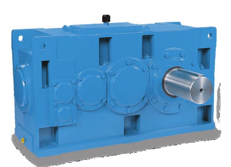

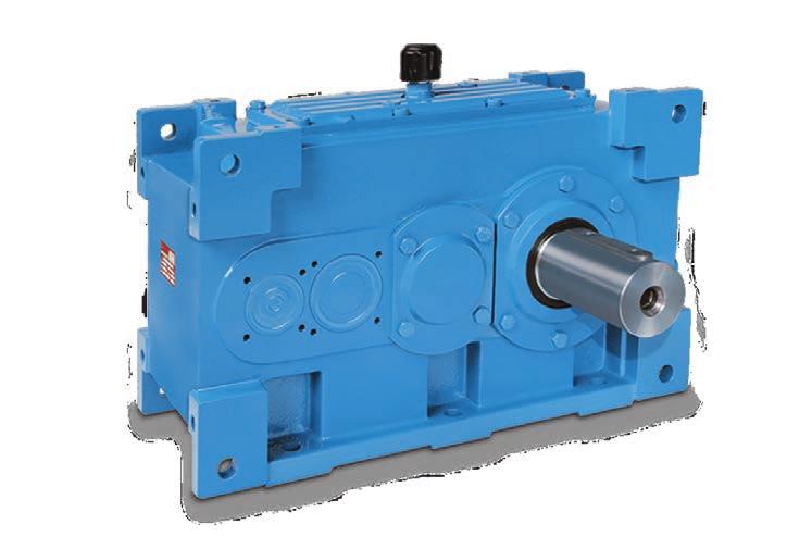

1 HELIAX Parallel/Orthogonal Gear Units with Ground Helical Gear Bipartite housing onobloc housing 1 Stage
2 Index Description Page General characteristics 2 Product designation 3-5 Selection guide lines 6-7 Service factors 8-9 Overhung loads / Permissible overhung loads -12 Torque ratings 13 Power ratings Gear ratios 17 Thermal Rating / Gear-unit weights 18 Dimensions ounting suggestions for driven machine s 64 Application Instructions - shrink disc 65 Backstop - complementary dimensions 66 Lubrication 67 Cooling 68 Technical information
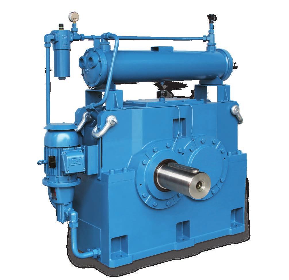
3 General Characteristics HELIAX gear-units have ground helical gears and parallel or orthogonal construction, available in gears ratios and Nm capacity. 1 Gear unit Housing Helimax gear units housing are in ductile iron. or size 65 housing is in welded steel plate. s 16 to 65 have a plit housing construction, allowing easy access to all components and facilitating maintenance. An inspection cover located on top of the gear unit housing allows quick examination of the gear unit parts without disassembling it from the driven machine. Output s The s are made of alloy steel and thermally treated. All seats and output bores are machined to the clearences indicated in this catalogue. Gears Gears are manufactured in high-quality alloy-steel and, after hobbing, subjected to carburizing and quenching treatments. Tooth flanks are ground by the generation process. Bearings Self-aligning spherical roller bearings or tapered roller bearings specifically for the loads indicated. Lubrication Bearings and gears are usually lubricated by immersion or when necessary by oil pump pressure. The bottom of the housing serves as the oil reservoir. Cooling In most cases, the heat radiated by the outer surface is sufficient to maintain the system in a suitable thermal regime. When necessary, a colling coil or external heat-exchanger may be employed for additional cooling. Supply Information Gear units are supplied without lubricating oil. The interior of the box is coated with oil-resistant paint. Shaft ends are protected against corrosion. The gear-units are supplied painted with synthetic enamel, either WEG-CESTARI standard or to client specification. Optional items (on request) - an - Top base for electric motor - Welded steel-plate housing - Labyrinth Seals (Taconite) When high levels of dust are present in the environment the use of labyrinth (Taconite) seals may be necessary in gear units; in this case, the dimensions of the housing center to the tip of the input and to the output (see pages 19-63) may be longer (please consult WEG-CESTARI). 2
 R orced lubrication and cooling (please consult) S Colling oil")
 Shaft orientation IEC otor frame 0 No motor L 1 D 1L E 90S N 90L P L G H 112 J 132S K 132 2, B using the foot bores of the housing to")
 or Gear-units with shrink disc, see page 64.")
4 Product Code E P odel Number of Stages 2 3 Gear Ratio Double Triple 19 9, ,0 20, , ,2 25, ,5 29, , , , , , , ,0 34, , , ,0 38,0 ounting Position 0 No colling system L Colling Systems orced lubrication (please consult) R orced lubrication and cooling (please consult) S Colling oil Backstop 0 Without backstop 1 With backstop 3 backstop ready 4 Customer provided 0 Solid input (S.I.S.) 4 S.I.S. + Electric motor SRID (without motor) 5 S.I.S. + Electric motor SRID (Electric motor supplied by WEG-CESTARI) 6 S.I.S. + Electric motor SRID (Electric motor supplied by costumer) Shaft orientation IEC otor frame 0 No motor L 1 D 1L E 90S N 90L P L G H 112 J 132S K 132 2, B using the foot bores of the housing to attach the gear-unit Output: Keyed hollow , B using the side bores of the housing to attach the gear-unit Output: Solid Output: Hollow with Shrink disc Torque arm mounting The need for lubrication systems and/or cooling should be evaluated for vertical working positions (please consult WEG-CESTARI) or Gear-units with shrink disc, see page 64. When using electric motors in the vertical position and the motor downwards the use of protective cover for electric motors is recommended. 3

 2 IEC adapter (electricmotor supplied by WEG-CESTARI) 3 IEC adapter (electric motor supplied by customer) 4 S.I.S. + Electric motor SKID (without motor) 5 S.")


5 Product Code E P odel Number of Stages Gear Ratio Double Triple Triple 16 6, , ,0 17 7, , ,0 25, ,0 29, , , , , , , , , ,0 34, , , , , , No colling system L ounting Position Colling Systems orced lubrication (please consult) R orced lubrication and cooling (please consult) S Colling oil Backstop 0 Without backstop 1 With backstop 3 backstop ready 4 Customer provided Input Type 0 Solid input 1 IEC adapter (with motor) 2 IEC adapter (electricmotor supplied by WEG-CESTARI) 3 IEC adapter (electric motor supplied by customer) 4 S.I.S. + Electric motor SKID (without motor) 5 S.I.S. + Electric motor SKID (Electric motor supplied by WEG-CESTARI) 6 S.I.S. + Electric motor SKID (Electric motor supplied by costumer) IEC otor frame 0 no motor H 112 R 200L J 132S S 225S D K 132 T 225 E 90S L 1 U 2 90L 1L V 0 G N W 315 P L X 355 Q 200 Set up Parallel s Parallel s Torque arm mounting parallel input s Orthogonal s Orthogonal s Torque arm mounting orthogonal Input: Parallel Output: Solid Input: Parallel Output: Hollow Input: Parallel Output: Shrink disc Input: Orthogonal Output: Solid Input: Orthogonal Output: Hollow Input: Orthogonal Output: Shrink disc The need for lubrication systems and/or cooling should be evaluated for vertical working positions (please consult WEG-CESTARI) or Gear-units with shrink disc, see page 64. When using electric motors in the vertical position and the motor downwards the use of protective hat for electric motors is recommended. 4
6 Product Code E P odel Number of Stages Gear Ratio Double Triple Quadruple 16 6, , ,0 17 7, , ,0 25, ,0 29, , , , , , , , , ,0 34, , , , , , Backstop 0 Without 1 With 3 Prepared for 4 Client s own Input Type 0 Solid input 1 IEC adapter (with motor) 2 IEC adapter (electricmotor supplied by WEG-CESTARI) 3 IEC adapter (electric motor supplied by customer) 4 S.I.S. + Electric motor SKID (without motor) 5 S.I.S. + Electric motor SKID (Electric motor supplied by WEG-CESTARI) 6 S.I.S. + Electric motor SKID (Electric motor supplied by costumer) 2 Colling Systems 0 No colling system L orced lubrication (please consult) R orced lubrication and cooling (please consult) S Colling oil ounting Position IEC otor frame J 132S R 200L K 132 S 225S L 1 T no motor 1L U 2 N V 0 P L W 315 Q 200 X 355 Layout Parallel s Orthogonal s Input: Parallel Output: Hollow Parallel s Orthogonal s Input: Parallel Output: Solid Input: Orthogonal Output: Solid Torque arm mounting parallel s Torque arm mounting orthogonal s The need for lubrication systems and/or cooling should be evaluated for vertical working positions (please consult WEG-CESTARI) When using electric motors in the vertical position and the motor downwards the use of protective hat for electric motors is recommended Input: Orthogonal Output: Hollow 25 Positions Q and S for gear-unit size 65 on request. Gear-units with shrink disc (please consult WEG-CESTARI). 5
7 Selection Guide Lines 3 1) Required information To choose the most appropriate HELIAX gear unit, power to be transmitted, revolutions per minute of the gear-unit input and output s, the type of machine being operated and the operating cycle of the machine should be known. Service actor HELIAX gear-units are calculated for a service factor of 1; i.e. shock-free operation and operating time of up to hours/day at a room temperature of 30 C. The service factor (S), quantifies the influence of external conditions on the operation of the gear unit and depends on the type of operations carried out by the machine being driven. Table 2 (p. 8) indicates different types of load: U (uniform), (moderate shock load) and (heavy shock load) for most common applications. The type of load, the type of engine and the number of hours/day of operation determine the corresponding S in Table 3 (p. 9). 3) Determining the nominal power Nominal or rated power (Pn) is determined by multiplying the effective power absorbed by the machine (Pa) by the Service actor (S). 4) Checking thermal output capacity Permissible thermal output of the gear unit must be checked according to the following formulas: When: Pn = Pa.S PT = PTG.fa.fb.fc.ft (I); use of a complementary cooling system is not necessary; where: PT: permissible thermal capacity PTG: thermal capacity (p. 18) fa: ambient temperature factor, Table 1 (p. 7) fb: duration of operation factor, Table 1 (p. 7) fc: environment factor, Table 1 (p. 7) ft: maximum oil temperature, Table 1 (p. 7). If the previous conditions (I) are not met, check the thermal capacity of the gear-unit with a calling coil: where: PTK: Thermal capacity with calling coil (p. 18). If neither of the previous conditions are met (I and II) a heat exchanger must be used with the gear-unit (in this case, please consult WEG-CESTARI). IPORTANT: a) When the use of a heat exchanger is required, lubrication should be forced. b) When pressure lubrication and a cooling system are necessary, cooling should be by heat exchanger. 5) Selection of gear-unit The gear ratio (i) is obtained by dividing the input rotation (n1) by the output rotation (n. The reduction ratio (i) and the nominal power (Pn) determine the correct gear-unit in the tables on pages 14, 15 and 16. The power of the gear-unit listed in the catalogue must be equal to or greater than the nominal power required as obtained by the formula expressed in item 3, and the thermal power should be checked as in item 4. or rotations (n1) above 0 rpm and below 300 rpm, please consult WEG-CESTARI. or rotations ranging from 300 rpm to 900 rpm, the mechanical power is determined by the following formula: Where: P = Rated power at n rpm P (900) = power at 900 rpm. n = desired rotation (rpm) PT = PTK.fa.fb.fc.ft (II); P = P(900). n 900 6
8 Gear-unit Selection 6) Gear unit selection example A conveyor belt needs to be driven by a gear unit driven by an electric motor. The application has the following characteristics: Gear unit output speed: 26 rpm Electric motor speed: 0 rpm Operating conditions: 12 hours/day 30ºC Absorbed power: kw a) In table 2, page 8 it is found a moderate load classification for a conveyor belt with intermitent load. b) According to table 3, page 9, a moderate load application driven by electric motor for 12 hour/day shall have a service factor of 1.5 c) The nominal power (Pn) will be: Pn = Pt x S = x 1. Pn = 90 kw d) The required gear ratio will be: i = n1 (rpm) = 0 = 69,2 n2 (rpm) 26 e) On page 15 of this catalogue, gear unit size is indicated. Nominal Gear Ratio: i = 71 (3 stages) - exact ratio, refer to page 17, which can transmit 95 kw at 0 rpm. f) Checking thermal output ratings: Condition (I): Pa < PT Where PT = PTG.fa.fb.fc.ft Pa = kw PTG = 5 kw (p.18) (E 3 stages without colling coil) fa = 0.93 (room temperature 30 degrees) fb = 1.00 (continuous service) fc = 1.00 (environment: large enclosed area, air flow >1.4 m / s) ft = 1.00 (oil temperature maximum 95 degrees) < 5 x 0.93 x1.00 x 1.00 x 1.00 < 98 kw: OK Therefore, this application does not require additional cooling. 3 Table 1 actors for Thermal Output Ratings Room temperature in C fa Room-temperature actor actor fa 1,15 1,07 1,00 0,93 0,83 0,75 0,67 fb Operating-time actor % Operating time / hour 1,00 (continuous) 0, 0, 0,40 0,20 actor fb 1,00 1,05 1,15 1,35 1, fc - Environmental actor Types of environment actor fc Open area, air flow > 3.7m / s 1,40 Large enclosed area, air flow > 1.4 m / s 1,00 Restricted enclosed area, air flow > 0.5 m / s 0,75 ft Oil-temperature factor aximum desired oil temperature in C actor ft 85 0, ,00 (requires synthetic oil) see page 67 for recommendations. 1,13 7
9 Service actors (S) Table 2 Load classification 4 Load application Agitators Pure liquids Liquids of consistent density Liquids of varying density Bottling and canning U Cement Jaw crushers Rotor ills Ball and roller mills Ceramics Pug mills Extruders and mixers Clay crushers Brick and tile presses Classifiers Rotary Compressors Centrifugal Rotary piston Piston (single cylinder) Piston (two cylinders) irregularity coefficient <1: U U Conveyors Bucket, belt, chain, belt, screw: - Uniform loads U - Heavy and intermittent loads Cooling towers Cranes Cab, bridge drives Winch drive Crushers Ore and minerals Distilleries Cookers - continuous service Brew kettles, mash tubs continuous service ixers Dredges Winches, conveyors and pumps Rotary heads and screens Conveyer Elevators Skip hoist - uniform load Skip hoist - heavy load reight Bucket - normal load Bucket - heavy load Passenger ans Centrifugal ining or cooling towers eeders Screw Belt Load class U U U U U U U Load application Generators Alternators requency converters Hoists and Cranes oderate lifting Heavy lifting Rotary Translational ood Industry Cereal cookers Dough mixers, meat grinders, choppers Light centrifuges Heavy centrifuges Laundries Rotary dryers Washing machines Rack drive Lifts Rack jack Extraction machinery Lifting platforms - normal use Lifting platforms - heavy use Lifting platforms - inclined loads achine tools ain drive - Heavy loads ain drive - Uniform Loads Auxiliary drive Thread formers etallurgical Industries Circular saw Shears Bending machines Wire Drawers Straightening rollers Tape reels and sheet winders Laminators Tube welding machines ixers ixers Rubber Paper pulp luids with solids Clean fluids Oil industries Paraffin filter presses Pipe-line pumps Refining machines Rotary drill installations Load class U U U U Paper Agitators, mixers, bleachers, beaters, pulpers, calenders, presses Supercalenders Hydraulic and mechanical peelers Debarking drums elt stretchers Dryers Load application Pumps Centrifugal - low viscosity liquid Centrifugal - high viscosity liquid ulti-cylindrical dual-action Reciprocating positive displacement Rotary gear Submerged piston Pressure Rotary dryers and coolers ood products, pulp Rotary urnaces Rotary mills Ball and roller Hammer U U U Rubber and Plastic Calenders Laboratory equipment Extruders Laminators Plate machine Tubing machines and strainers Cylindrical mills 2 on line Cylindrical mills 3 on line Refiners Grinders and mixers Sieves Horizontal screens Air filtration Rotary for stones and sand Sanitation Aerators eeders, pumps, decanters ixing system filters and strainers Clarifiers U U Sugar industries ills Cane knives Crystallizers Textile industries Calenders, cards, spinners, twisters, Rovers and dyeing machines Timber Industries Planer feeder Saws, debarking drums, log transporters achines for wood working in general Transmissions Light transmissions Transmissions for machine tool drives Winders etal Paper Textiles U Uniform loads oderate shock loads Heavy shock loads Load class U U U Recommended minimum service factor of 2.00 or cooling towers a special gear-unit should be considered 8

10 Service actors (S) Table 3 Service factor S Load class of driven machine Uniform oderate shock load Heavy shock load Powered by Operation time U electric motor, steam turbine or Hydraulic motor ulti-cylinder combustion engine Single cylinder combustion engine intermittently up to 3 h / day 0, 1,00 1, up to h / day 1,00 1,25 1,75 over h / day 1,25 1, 2,00 intermittently up to 3 h / day 1,00 1,25 1,75 up to h / day 1,25 1, 2,00 over h / day 1, 1,75 2,25 intermittently up to 3 h / day 1,25 1, 2,00 up to h / day 1, 1,75 2,25 over h / day 1,75 2,00 2, 4 Overhung loads When power transmission is via elastic coupling, the gear-unit is not exposed to radial and/or axial loads; however if transmission is through elements mounted on the of the gear-unit (external gears, sprockets or pulleys), radial and/or axial loads will be present. On page the admissible overhung loads on the input and output s of the gear-unit may be obtained. Axial loads of up to 30% of the allowable overhung loads can be absorbed simultaneously with the radial loads. The values of the radial loads in the tables refer to the load applied to the center of the length L of the. When the distance of application (x) is different from L/2, there should be a recalculation according to the formulas and tables below: Determining the permissable overhung loads at a point x: (x) D r L/2 a) 1 (x) based on the operating of the bearing: 1(x) = k. r [N] m + x L x b) 2 (x) based on maximum flexion of the : 2(x) = 0.n [N] p + x where: x = distance from the shoulder to the force center [mm] r = radial force acting on the central point of the length from the tip of the L / 2 [N] To determine (x), 1(x) and 2(x) are calculated and the lowest value is chosen to represent (x). 9
11 Overhung Loads Table 4 Values for recalculation of the overhung load - input 5 2 stages 3 stages 4 stages k m n p d L k m n p d L k m n p d L Table 5 Values for recalculation of the overhung load - output k m n p d L
12 Overhung Loads inimum permissible diameter for the transmission element mounted on the As well as the overhung load obtained, the smallest allowable diameter for the transmission element (external gear, sprocket or pulleys) may be calculated using the following formula: Values for factor Kr lat belt with tensioner 2, lat belt without tensioner 5,00 V-belt without tensioner 1,75 Roller chain or silent chain 1,40 Gears 1,15 5 Dmin = c. Kr r Where: Dmin = inimum permissible diameter (mm) c = Torque to be transmitted (Nm) r = Permissable radial load on the gear-unit (N) Kr = Additional factor The bore of the element mounted on the input or output of the gear-unit must be machined to H7 cleareance. The elements mounted on the s must be aligned carefully even if elastic coupling is used. Do not tap the parts into place during assembly as this damages bearings and gear teeth. Suggested arrangement for gear-unit, depending on direction of rotation When direct coupling is not used to connect the gear-unit and machinery, the direction indication in the figures should be observed to avoid traction rupture at the base of the gear-unit. 11
13 R Permissable Overhung Load [N] Input Number of stages i total rpm input ,3 to 8 9,0 to 11,2 12,5 to to 25 to 45 to 4 90 to Output rpm output Up to to to to to to Loads for gear units with service factor 1.00; for other service factors refer to Cestari. 12
14 2 Nominal Output Torque 2 Estages Values in Nm i total , , , , , , , , , , Estages Values in Nm i total , , , , , , , , , , , , , Estages Values in Nm i total
15 P1 - Power Ratings in kw - 2 Stages i total Input rpm Output rpm Values in Nm , , , , , , , , , , , ,3 94, , , ,7 84, , , ,0 76, , , ,3 88, ,0 66,0 92, , ,2 99, ,6 79, ,9 59,6, kw = 1.36 CV = 1.34 HP 1 kw = 1.36 CV = 1.34 HP kw = 1,36 cv Pressure lubrication necessary 14
16 P1 - Power Ratings in kw - 3 Stages i total Input rpm Output rpm Values in Nm ,0 94, ,2 78, ,4 62,8 96, ,5 47,1 72,1 82, ,4 91, , ,7 76, ,0 61,3 86, ,2 46,0 65,2 81, ,6 83, ,7 69,4 95, ,7 55,5 76, , ,8 41,6 57,2 82, ,8 72, ,0,7 85, ,2 48,5 68,6 94, , ,4 36,4 51,4 71, ,8 65,5 91, , ,0 54,6 76, , ,2 43,7,8 87, , ,4 32,8 45,6 65,5 88, ,9 58,1 82, , ,1 48,4 68,7 96, , ,3 38,8 54,9 76, ,0 9, ,5 29,1 41,2 57,7 77, ,4 52,7 72, , ,1 43,9,2 86, , ,9 35,1 48,2 69,2 93, ,0 8, ,7 26,3 36,1 51,9,0 98, ,1 46,0 65,0 90, , ,6 38,4 54,2 75, ,0 9, ,1 30,7 43,3,0 83, ,0 7,0 16,5 23,0 32,5 45,0 62,9 88, , ,1 42,4 57,8, , ,1 35,3 48,2 67,1 92, ,0 8, ,0,2 38,6 53,6 74, ,0 6,0 9,0 15,0 21,2,9 40,2 55,5 78, , ,2 37,6 52,5 72,4 99, ,0 9, ,8 31,4 43,8,3 82, ,0 7, ,5 25,1 35,0 48,2 66,3 97, ,0 6,0 8,0 13,1 18,8 26,3 36,2 49,7 72, , ,0 33,5 45,5 65,4 89, ,0 8, ,1 27,9 37,9 54,5 74, ,0 7,0 15,3 22,3 30,3 43,6 59,7 84, ,0 5,0 7,0 11,5 16,7 22,7 32,7 44,8 63,5 90, ,0 9, ,8 29,8 40,9 56,7 77, ,0 7, ,3 24,8 34,1 47,3 64,8 95, ,0 6,0 9,0 13,9 19,9 27,3 37,8 51,8 76, ,0 4,0 6,0,4 14,9 20,4,4 38,9 57,2, ,0 8, ,3 26,7 36,0,5,2 99, ,0 7,0 9,0 15,3 22,2 30,0 42,0 58,5 82, ,0 5,0 8,0 12,2 17,8 24,0 33,6 46,8 66,3 94, ,0 4,0 6,0 9,16 13,3 18,0 25,2 35,1 49,8, kw = 1.36 CV = 1.34 HP Pressure lubrication necessary 7 15
17 P1 - Power Ratings in kw - 4 Stages i total Input rpm Output rpm Values in kw ,6 23,4 33,0 46,0 63,0 89, ,8 19,5 27,5 38,3 52,5 74, ,1 15,6 22,0 30,7 42,0 59,6 84, ,31 11,7 16,5 23,0 31,5 44,7 63,3 91, ,0 21,2,9 40,2 56,9, ,5 17,7 24,1 33,5 47,5 67,3 92, ,0 14,1 19,3 26,8 38,0 53,8 74, ,0 7,52,6 14,5 20,1,5 40,4 55,8, ,1 18,4 26,4 36,7,0, ,9 15,4 22,0 30,6 41,6 59,0 83, ,72 12,3 17,6 24,5 33,3 47,2 66, ,0 6,54 9,21 13,2 18,4 25,0 35,4,2 72,5 97, ,9 16,8 23,4 32,5 44,9 63,7 90, ,92 14,0 19,5 27,1 37,5 53,1 75, ,6 7,94 11,2 15,6 21,7 30,0 42,5,2 86, ,2 5,95 8,39 11,7 16,3 22,5 31,9 45,1 65,2 88, ,1 14,7 20,6,8 39,8 56,5, ,44 12,3 17,1 24,0 33,2 47,1 66,7 96, ,6 6,75 9,83 13,7 19,2 26,6 37,7 53,3 76, ,4 5,06 7,37,3 14,4 19,9,2 40,0 57,6 78, ,16 13,3 18,0 25,2 36,0 51,0, ,4 7,64 11,1 15,0 21,0 30,0 42,5 58,7 84, ,5 6,11 8,89 12,0 16,8 24,0 34,0 47,0 67,6 91, ,6 4,58 6,67 8,99 12,6 18,0 25,5 35,2,7 68,6 98, ,97 11,6 16,4 23,0 31,6 44,8 63,4 91, ,3 6,64 9,67 13,7 19,2 26,3 37,3 52,9 76, ,7 5,31 7,73,9 15,4 21,1 29,9 42,3,9 81, ,0 3,98 5, 8,21 11,5 15,8 22,4 31,7 45,6 61,0 87, ,0 7,25,6 14,5 20,4,4 40,3 57,1 82, ,5 6,05 8, 12,1 17,0 23,7 33,6 47,6 68,4 92, ,0 4,84 7,04 9,69 13,6 18,9 26,9 38,0 54,7 73, ,5 3,63 5, 7,27,2 14,2 20,1,5 41,1 55,5 79, ,0 6,55 9,53 13,2 18,5 25,3 35,8,3 72,5 97, ,7 5,45 7,94 11,0 15,4 21,1 29,9 42,0,4 81, ,4 4,36 6,35 8,81 12,4 16,9 23,9 33,6 48,3 64,8 92, ,0 3,27 4,76 6,61 9,27 12,6 17,9 25,2 36,2 48,6 69, ,2 5,79 8,43 11,5 16,1 23,0 32,5 45,1 64,9 87, ,0 4,82 7,02 9,59 13,5 19,1 27,1 37,6 54,1 73, ,8 3,86 5,62 7,67,8 15,3 21,7 30,1 43,3 58,5 83, ,6 2,89 4,21 5,75 8,07 11,5 16,3 22,6 32,5 43,9 62, ,4 5,19 7,56,1 14,2 19,9,2 40,6 58,5 78, ,3 4,33 6,30 8,41 11,8 16,6 23,5 33,9 48,7 65,3 93, ,3 3,46 5,04 6,73 9,44 13,2 18,8 27,1 39,0 52,3 74, ,2 2, 3,78 5,05 7,08 9,94 14,1 20,3 29,2 39,2 56, ,7 4,58 6,67 9,14 12,8 17,9 25,3 35,2,7 69,7 99, ,8 3,82 5,56 7,62,7 14,9 21,1 29,4 42,3 58,1 83, ,8 3,05 4,45 6, 8,55 11,9 16,9 23,5 33,8 46,5 66, ,9 2,29 3,33 4,57 6,41 8,94 12,7 17,6 25,4 34,9, ,1 4,07 5,93 8,05 11,3 15,7 22,3 31,8 45,8 61,4 88, ,2 3,39 4,94 6,71 9,41 13,1 18,6 26,5 38,2 51,2 73, ,4 2,72 3,95 5,37 7,53,5 14,9 21,2 30,5 40,9 58, ,5 2,04 2,96 4,03 5,65 7,86 11,1 15,9 22,9 30,7 44, kw = 1.36 CV = 1.34 HP Pressure lubrication necessary 16
18 Exact Gear Ratios Parallel Shafts i total Number of stages ,3 6,2 6,149 6,477 6,3 6,277 6,149 6,6 6,6 6,351 6,293 6,257 6,392 6,420 6,381 7,1 6,922 6,922 7,173 6,883 7,218 6,922 7,174 7,174 7,258 7,183 7,071 7,138 7,087 7,146 8,0 7,857 7,857 8,143 7,867 8,143 7,857 8,036 8,044 7,958 8,241 7,857 8,024 8,143 8,033 9,0 8,5 9,214 8,730 8,730 8,730 9,161 8,8 9,214 8,793 8,839 8,839 8,957 9,047 8,839 8,893 9,120 8,531 2,0 9,718,538 9,6,067 9,6,179 9,730,6 9,821 9,925,040 9,857 9,927 9,821,114,022 9,665 11,2,694 11,451,913 11,262 11,000 11,496 11,6 11,451 11,131 11,092 11,092 11,256 11,179 11,196 11,085,919,992 12,5 12,277 12,893 12,017 12,522 12,277 12,440 12,292 12,723 12,440 12,522 12,277 12,469 12,237 12,199 12,390 12,769 12,349 14,0 13,996 14,4 13,881 13,866 13,634 14,2 13,767 14,114 13,881 13,866 14,241 14,2 13,985 14,0 14,204 13,984 13,978 16,0 15,452 16,6 15,434 15,976 15,714 15,7 15,471 16,014 15,714 16,238 15,945 16,046 16,225 16,176 16,471 15,4 15,969 18,0 17,548 18,186 17,548 17,959 17,398 18,186 17,569 18,186 17,8 17,959 17,679 18,186 17,831 17,679 17,831 17,914 17,140 20,0 19,861 20,721 19,747 19,8 20,000 20,255 19,568 20,175 19,612 19,412 19,664 19,833 20,414 20,446 20,242 19,464 20,073 22,4 21,924 22,902 21,825 22,524 22,5 22,417 22,212 22,902 22,262 22,185 22,185 22,513 22,866 22,926 22,698 21,341 23,031 25,0 24,954 26,337 25,099 24,669 24,895 25,546 24,6 25,446 25,045 24,958 25,4 25,193 25,153 25,192 24,941 24,021 25,2,0 27,6,929 26,995,451,471,401,459,290 27,827 27,439,023,141,242,613,3 26,435 27,742 31,5 32,588 32,907 31,753 31,429 31,633 32,041 30,955 32,041 31,379 31,429 31,339 32,041 32,561 32,3 32,561 31,934 31, ,5 35,973 36,371 35,095 35,918 35,666 35,462 35,138 36,371 35,619 35,918 35,357 36,371 36,473 36,199 36,511 35,014 35,912 40,0 40,944 41,827 40,3 39,339 39,374 40,413 39,042 40,413 40,071 40,408 40,009 40,1 40,120 39,777 40,120 39,411 39,421 45,0 45,417 45,943 43,407 45,371 45,030 44,929 45,020 44,929 44,524 44,425 44,662 45,464 45,047 45,179 45,568 43,371 43,257,0,136,920,2 48,889 48,932,516,364,920,6,8 49,721 51,526,347 49,916,347 49,5 48,713 56,0 54,398 57,588 57,030 56,122 55,094 55,627 56,001 56,830 54,418 56,122 55,246 57,588 56,837 55,246 55,722 54,863 53,324 63,0 62,392 64,185 61,878 63,9 61,9 64,256 62,008 63,115 62,333 62,857 61,6 64,256 62,933 64,085 64,638 62,0,941 71,0 72,038 72,743,190,639 69,592 71,444 71,447 72,743 69,143,639 69,536 72,743 73,2 71,754 72,373,3,1,0 77,989 81,836 79,939,218 77,711 81,230,315,537 79,549,218 78,964 82,442 81,514 79,554,,017 77,0 90,0 87,593 87,669 88,403 88,137 89,716 88,599 89,343 87,4 90,171 88,7 88,487 88,6 87,263 88, ,778 97,864 1,032,7 99,294 98,057 1,417 99,442 3,052,693 99,832,693 99,055 99, , ,543 1,654 1, , , ,685 1, , ,2 112, ,681 1,848 9, ,9 123, , , ,2 124, , , ,4 124, ,3 125, , , , , , , , , , ,1 144, , , , , , , , ,459 1, , ,121 1, , , , ,7 1,4 1, , ,1 178, , ,9 178, , , , , ,406, , , , , , , , , , , , , , , ,0 200, , ,6 217, , , , ,9 224,6 221, 232, , , , , , , , ,842 2, , ,327 2,6 246, , , ,5 254, , , , ,274 9,3 6,122 4,563 1, , ,053 8,547 5, ,786 3,515 2, , ,871 3, ,3 315, , , , , , , , ,9 320, , ,9 349, , , , , ,2 349, , , , , , ,200 or exact gear ratios for orthogonas units, please consult WEG-CESTARI 17
19 Thermal Ratings Thermal ratings, PT, kw Thermal ratings with cooling coil, PTK, kw 2 stages 3 stages 4 stages 2 stages 3 stages 4 stages or sizes, 54, 58, and 65 cooling by heat exchanger is recommended; a cooling coil should only be used on consultation with WEG-CESTARI. 9 Weight of gear-units kgf
20 Gear-units with Parallel Shafts 2 and 3 Stages Dimensions 2 Stages 3 Stages oot mounting 305, ø17 (8) Holes , ø17 (8) Holes ø17 1 (6) Holes ø (6) Holes Torque arm 237 6,35 305, , ,35 305, , k k Protection cap Input 2 stages Input 3 stages Single solid Keyed hollow Hollow with shrink disc H7 59, H7 55-m H solid output 1) Keys according to DIN Sheet 1 (see Table - page ) According to DIN 332/1 (see Table 11 - page ) Keyed hollow output Hollow output with shrink disc 19
21 Dimensions 12 2 Stages Gear-units with Parallel Shafts 3 Stages 2 and 3 Stages 343, ø20 (8) Holes , ø20 (8) Holes oot mounting ø20 (6) Holes ø (6) Holes ,35 343, , ,35 343, ,5 Torque arm k k Protection cap Input 2 stages Input 3 stages Single solid Keyed hollow Hollow with shrink disc H7 69, H m H solid output 1) Keys according to DIN Sheet 1 (see Table - page ) According to DIN 332/1 (see Table 11 - page ) Keyed hollow output Hollow output with shrink disc 20
 Holes")
 Holes 2 5 2 1 5 327 1 Torque arm 271 6,35")


 According to DIN 332/1 (see Table")
22 Gear-units with Parallel Shafts 2 and 3 Stages Dimensions 14 2 Stages 3 Stages oot mounting 385, ø (8) Holes ,5 ø20 (8) Holes ø (6) Holes ø (6) Holes Torque arm 271 6,35 385, , ,35 385, , k6 8 -k Protection cap Input 2 stages Input 3 stages Single solid Keyed hollow Hollow with shrink disc H7 79, , H7 75-m H Solid output Keyed hollow output Hollow output with shrink disc 1) Keys according to DIN Sheet 1 (see Table - page ) According to DIN 332/1 (see Table 11 - page ) 21
23 Dimensions 16 Gear-units with Parallel Shafts 2 Stages ø24 (6) Holes oot mounting Housing mounting Torque arm k Protection cap Input Single solid Keyed hollow Hollow with shrink disc 87,5 72-H H7 79, m H Solid output 1) Keys according to DIN Sheet 1 (see Table - page ) According to DIN 332/1 (see Table 11 - page ) Keyed hollow output Hollow output with shrink disc 22
24 Gear-units with Parallel and Orthogonal Shafts 3 Stages Dimensions 16 Parallel Orthogonal oot mounting ø24 (6) Holes ø24 (6) Holes Housing mounting Torque arm k6 32-k Protection cap Parallel Input Orthogonal Input Single solid Keyed hollow Hollow with shrink disc 87,5 72-H H7 79, m H Solid output 1) Keys according to DIN Sheet 1 (see Table - page ) According to DIN 332/1 (see Table 11 - page ) Keyed hollow output Hollow output with shrink disc 23
 Holes 24 330 2 230 290 330 405 24 oot mounting Housing mounting Torque arm 27 31 8 8 24-k6 8 -k6")
25 Dimensions 16 Parallel Gear-units with Parallel and Orthogonal Shafts Orthogonal 4 Stages ø24 (6) Holes ø24 (6) Holes oot mounting Housing mounting Torque arm k6 8 -k Protection cap Parallel Input 1 90 Orthogonal Input Single solid 79,9 Keyed hollow Hollow with shrink disc ,5 72-H H7 85-m H Solid output 1) Keys according to DIN Sheet 1 (see Table - page ) According to DIN 332/1 (see Table 11 - page ) Keyed hollow output Hollow output with shrink disc 24
 Holes 2 3 Housing mounting 445 3 300 75 7 316 159 640 65 24 2 335 7 316 194")

 Keyed hollow output Hollow output with shrink")
26 2 Stages Gear-units with Parallel Shafts Dimensions oot mounting ø24 (6) Holes 2 3 Housing mounting Torque arm k Protection cap Input Single solid Keyed hollow Hollow with shrink disc 95 -H H7 95, m H Solid output 1) Keys according to DIN Sheet 1 (see Table - page ) According to DIN 332/1 (see Table 11 - page ) Keyed hollow output Hollow output with shrink disc 25
 Holes 65 24 300 3 2 3 3 445 2 24 oot mounting Housing mounting Torque")
 Keys according to DIN 6885 - Sheet 1 (see Table - page ) According to DIN 332/1 (see Table 11 - page ) Keyed hollow output Hollow output with shrink")
27 Dimensions 18 Parallel Gear-units with Parallel and Orthogonal Shafts Orthogonal 4 Stages ø24 (6) Holes ø24 (6) Holes oot mounting Housing mounting Torque arm k6 38-k Protection cap Parallel Input Orthogonal Input Single solid Keyed hollow Hollow with shrink disc 95 -H H7 95, m H Solid output 1) Keys according to DIN Sheet 1 (see Table - page ) According to DIN 332/1 (see Table 11 - page ) Keyed hollow output Hollow output with shrink disc 26
28 Gear-units with Parallel and Orthogonal Shafts 4 Stages Dimensions 18 Parallel Orthogonal oot mounting ø24 (6) Holes ø24 (6) Holes 2 3 Housing mounting Torque arm k6 8 -k Protection cap Parallel Input Orthogonal Input Single solid Keyed hollow Hollow with shrink disc 95 -H H7 95, m H Solid output 1) Keys according to DIN Sheet 1 (see Table - page ) According to DIN 332/1 (see Table 11 - page ) Keyed hollow output Hollow output with shrink disc 27
29 Dimensions 20 Gear-units with Parallel Shafts 2 Stages ø (6) Holes oot mounting Housing mounting Torque arm 51, k Protection cap Input Single solid Keyed hollow Hollow with shrink disc 7,5 90-H H7 6, m6 -H Solid output 1) Keys according to DIN Sheet 1 (see Table - page ) According to DIN 332/1 (see Table 11 - page ) Keyed hollow output Hollow output with shrink disc
30 Gear-units with Parallel and Orthogonal Shafts 3 Stages Dimensions 20 Parallel Orthogonal oot mounting ø (6) Holes ø (6) Holes Housing mounting Torque arm k6 38-k Protection cap Parallel Input Orthogonal Input Single solid Keyed hollow Hollow with shrink disc 7,5 90-H H7 6, m6 -H Solid output 1) Keys according to DIN Sheet 1 (see Table - page ) According to DIN 332/1 (see Table 11 - page ) Keyed hollow output Hollow output with shrink disc 29
31 Dimensions 20 Parallel Gear-units with Parallel and Orthogonal Shafts Orthogonal 4 Stages ø (6) Holes ø (6) Holes oot mounting Housing mounting Torque arm k6 32-k Protection cap Parallel Input Orthogonal Input Single solid Keyed hollow Hollow with shrink disc 7,5 90-H H7 6, m6 -H Solid output 1) Keys according to DIN Sheet 1 (see Table - page ) According to DIN 332/1 (see Table 11 - page ) Keyed hollow output Hollow output with shrink disc 30
32 2 Stages Gear-units with Parallel Shafts Dimensions oot mounting ø (6) Holes Housing mounting Torque arm m Protection cap Input Single solid Keyed hollow Hollow with shrink disc 120 -H7 5 2-H7 116, m H Solid output 1) Keys according to DIN Sheet 1 (see Table - page ) According to DIN 332/1 (see Table 11 - page ) Keyed hollow output Hollow output with shrink disc 31
33 Dimensions 23 Parallel Gear-units with Parallel and Orthogonal Shafts Orthogonal 3 Stages ø (6) Holes ø (6) Holes oot mounting Housing mounting Torque arm 41 51, k k Protection cap Parallel Input Orthogonal Input Single solid Keyed hollow Hollow with shrink disc 120 -H7 5 2-H7 116, m H Solid output 1) Keys according to DIN Sheet 1 (see Table - page ) According to DIN 332/1 (see Table 11 - page ) Keyed hollow output Hollow output with shrink disc 32
34 Gear-units with Parallel and Orthogonal Shafts 4 Stages Dimensions 23 Parallel Orthogonal oot mounting ø (6) Holes ø (6) Holes Housing mounting Torque arm k6 32-k Protection cap Parallel Input Orthogonal Input Single solid Keyed hollow Hollow with shrink disc 120 -H7 5 2-H7 116, m H Solid output 1) Keys according to DIN Sheet 1 (see Table - page ) According to DIN 332/1 (see Table 11 - page ) Keyed hollow output Hollow output with shrink disc 33
35 Dimensions 25 Gear-units with Parallel Shafts 2 Stages ø35 (6) Holes oot mounting Housing mounting Torque arm m Protection cap Input Single solid Keyed hollow Hollow with shrink disc H H7 127, m H Solid output 1) Keys according to DIN Sheet 1 (see Table - page ) According to DIN 332/1 (see Table 11 - page ) Keyed hollow output Hollow output with shrink disc 34
36 Gear-units with Parallel and Orthogonal Shafts 3 Stages Dimensions 25 Parallel Orthogonal oot mounting ø35 (6) Holes ø (6) Holes Housing mounting Torque arm , k k Protection cap Parallel Input Orthogonal Input Single solid Keyed hollow Hollow with shrink disc H H7 127, m H Solid output 1) Keys according to DIN Sheet 1 (see Table - page ) According to DIN 332/1 (see Table 11 - page ) Keyed hollow output Hollow output with shrink disc 35
37 Dimensions 25 Parallel Gear-units with Parallel and Orthogonal Shafts Orthogonal 4 Stages ø35 (6) Holes ø35 (6) Holes oot mounting Housing mounting Torque arm Tipos de saída k6 38-k Protection cap Parallel Input Orthogonal Input Single solid Keyed hollow Hollow with shrink disc H H7 127, m H Solid output 1) Keys according to DIN Sheet 1 (see Table - page ) According to DIN 332/1 (see Table 11 - page ) Eixo de saída vazado chavetado Hollow output with shrink disc 36
38 2 Stages Gear-units with Parallel Shafts Dimensions oot mounting ø35 (6) Holes Housing mounting Torque arm , m Protection cap Input Single solid Keyed hollow Hollow with shrink disc H H7 137, m H Solid output 1) Keys according to DIN Sheet 1 (see Table - page ) According to DIN 332/1 (see Table 11 - page ) Keyed hollow output Hollow output with shrink disc 37
 Holes 3 330 4 4 4 1 13 85 0 1 13 7 120 2 300 115 35 4 5 120 5 655 2 200 4 42 36 35 oot mounting Housing mounting Torque arm 51,5")
39 Dimensions Parallel Gear-units with Parallel and Orthogonal Shafts Orthogonal 3 Stages ø35 (6) Holes ø (6) Holes oot mounting Housing mounting Torque arm 51, k m Protection cap Parallel Input Orthogonal Input Single solid Keyed hollow Hollow with shrink disc ,4 130-H H m H Solid output Keyed hollow output Hollow output with shrink disc 1) Keys according to DIN Sheet 1 (see Table - page ) According to DIN 332/1 (see Table 11 - page ) 38
40 Gear-units with Parallel and Orthogonal Shafts 4 Stages Dimensions Parallel Orthogonal oot mounting ø35 (6) Holes ø35 (6) Holes Housing mounting Torque arm k6 38-k Protection cap Parallel Input Orthogonal Input Single solid Keyed hollow Hollow with shrink disc , H H m H Solid output Keyed hollow output Hollow output with shrink disc 1) Keys according to DIN Sheet 1 (see Table - page ) According to DIN 332/1 (see Table 11 - page ) 39
41 Dimensions 32 Gear-units with Parallel Shafts 2 Stages ø42 (6) Holes oot mounting ixação tampa a tampa Torque arm m Protection cap Input Single solid Keyed hollow Hollow with shrink disc H H7 158, m H Solid output Keyed hollow output Hollow output with shrink disc 1) Keys according to DIN Sheet 1 (see Table - page ) According to DIN 332/1 (see Table 11 - page ) 40
42 Gear-units with Parallel and Orthogonal Shafts 3 Stages Dimensions 32 Parallel Orthogonal oot mounting ø42 (6) Holes ø (6) Holes Housing mounting Torque arm m m Protection cap Parallel Input Orthogonal Input Single solid Keyed hollow Hollow with shrink disc H H7 158, m H Solid output Keyed hollow output Hollow output with shrink disc 1) Keys according to DIN Sheet 1 (see Table - page ) According to DIN 332/1 (see Table 11 - page ) 41
43 Dimensions 32 Parallel Gear-units with Parallel and Orthogonal Shafts Orthogonal 4 Stages ø42 (6) Holes ø42 (6) Holes oot mounting Housing mounting Torque arm 51,5 51, k k Protection cap Parallel Input Orthogonal Input Single solid Keyed hollow Hollow with shrink disc H H7 158, m H Solid output 1) Keys according to DIN Sheet 1 (see Table - page ) According to DIN 332/1 (see Table 11 - page ) Keyed hollow output Hollow output with shrink disc 42
44 2 Stages Gear-units with Parallel Shafts Dimensions Dimensões oot mounting ø42 (6) Holes 4 5 Housing mounting Torque arm m Protection cap Input Single solid Keyed hollow Hollow with shrink disc H H7 179, m H Solid output 1) Keys according to DIN Sheet 1 (see Table - page ) According to DIN 332/1 (see Table 11 - page ) Keyed hollow output Hollow output with shrink disc 43
45 Dimensions 36 Parallel Gear-units with Parallel and Orthogonal Shafts Orthogonal 3 Stages ø42 (6) Holes ø (6) Holes oot mounting Housing mounting Torque arm , m6 20 -m Protection cap Parallel Input Orthogonal Input Eixo solid iimples Keyed hollow Hollow with shrink disc H H7 179, m H Solid output Keyed hollow output Hollow output with shrink disc 1) Keys according to DIN Sheet 1 (see Table - page ) According to DIN 332/1 (see Table 11 - page ) 44
46 Gear-units with Parallel and Orthogonal Shafts 4 Stages Dimensions 36 Parallel Orthogonal oot mounting ø42 (6) Holes ø42 (6) Holes 4 5 Housing mounting Torque arm ,5 51, k k Protection cap Parallel Input Orthogonal Input Single solid Keyed hollow Hollow with shrink disc H H7 179, m6 1-H Solid output Keyed hollow output Hollow output with shrink disc 1) Keys according to DIN Sheet 1 (see Table - page ) According to DIN 332/1 (see Table 11 - page ) 45
47 Dimensions 40 Gear-units with Parallel Shafts 2 Stages ø48 (6) Holes oot mounting Housing mounting Torque arm m Protection cap Input Single solid Keyed hollow Hollow with shrink disc , H H7 2 2-m6 200-H Solid output Keyed hollow output Hollow output with shrink disc 1) Keys according to DIN Sheet 1 (see Table - page ) According to DIN 332/1 (see Table 11 - page ) 46
48 Gear-units with Parallel and Orthogonal Shafts 3 Stages Dimensions 40 Parallel Orthogonal oot mounting ø48 (6) Holes ø (6) Holes Housing mounting Torque arm , m6 74, m Protection cap Parallel Input Orthogonal Input Single solid Keyed hollow Hollow with shrink disc , H H7 2 2-m6 200-H Solid output Keyed hollow output Hollow output with shrink disc 1) Keys according to DIN Sheet 1 (see Table - page ) According to DIN 332/1 (see Table 11 - page ) 47
49 Dimensions 40 Parallel Gear-units with Parallel and Orthogonal Shafts Orthogonal 4 Stages ø48 (6) Holes ø48 (6) Holes oot mounting Housing mounting Torque arm m m Protection cap Parallel Input Orthogonal Input Single solid Keyed hollow Hollow with shrink disc H H7 2, m6 200-H Solid output Keyed hollow output Hollow output with shrink disc 1) Keys according to DIN Sheet 1 (see Table - page ) According to DIN 332/1 (see Table 11 - page ) 48
50 2 Stages Gear-units with Parallel Shafts Dimensions oot mounting ø48 (6) Holes 5 6 Housing mounting Torque arm m Protection cap Input Single solid Keyed hollow Hollow with shrink disc ,9-H ,2-H7 231, m6 220-H , Solid output Keyed hollow output Hollow output with shrink disc 1) Keys according to DIN Sheet 1 (see Table - page ) According to DIN 332/1 (see Table 11 - page ) 49
51 Dimensions 46 Parallel Gear-units with Parallel and Orthogonal Shafts Orthogonal 3 Stages ø48 (6) Holes ø (6) Holes oot mounting Housing mounting Torque arm m6 22 -m Protection cap Parallel Input Orthogonal Input Single solid Keyed hollow Hollow with shrink disc ,9-H ,2-H7 231, m6 Solid output 220-H7 7 Keyed hollow output 203, Hollow output with shrink disc 1) Keys according to DIN Sheet 1 (see Table - page ) According to DIN 332/1 (see Table 11 - page )
52 Gear-units with Parallel and Orthogonal Shafts 4 Stages Dimensions 46 Parallel Orthogonal oot mounting ø48 (6) Holes ø48 (6) Holes 5 6 Housing mounting Torque arm m m Protection cap Parallel Input Orthogonal Input Single solid Keyed hollow Hollow with shrink disc ,9-H ,2-H , m6 220H , Solid output Keyed hollow output Hollow output with shrink disc 1) Keys according to DIN Sheet 1 (see Table - page ) According to DIN 332/1 (see Table 11 - page ) 51
53 Dimensions Gear-units with Parallel Shafts 2 Stages ø48 (6) Holes oot mounting Housing mounting Torque arm m6 Input Single solid Keyed hollow ,4 2-m H Solid output 1) Keys according to DIN Sheet 1 (see Table - page ) According to DIN 332/1 (see Table 11 - page ) Keyed hollow output or sizes to 65, please consult Cestari. 52
54 Gear-units with Parallel and Orthogonal Shafts 3 Stages Dimensions Parallel Orthogonal oot mounting ø48 (6) Holes ø48 6 (6) Holes ixação tampa a tampa Torque arm m m6 Parallel Input Orthogonal Input Single solid Keyed hollow ,4 2-m H Solid output Keyed hollow output 1) Keys according to DIN Sheet 1 (see Table - page ) According to DIN 332/1 (see Table 11 - page ) or sizes to 65, please consult Cestari. 53
55 Dimensions Parallel Gear-units with Parallel and Orthogonal Shafts Orthogonal 4 Stages ø48 (6) Holes ø48 (6) Holes oot mounting Housing mounting Torque arm 74, , m6 20 -m Parallel Input Orthogonal Input Single solid Keyed hollow , m H Solid output 1) Keys according to DIN Sheet 1 (see Table - page ) According to DIN 332/1 (see Table 11 - page ) Keyed hollow output or sizes to 65, please consult Cestari. 54
56 2 Stages Gear-units with Parallel Shafts Dimensions oot mounting ø48 (6) Holes 6 7 Housing mounting Torque arm m6 Input Single solid Keyed hollow ,4 290-m H7 8 Solid output 1) Keys according to DIN Sheet 1 (see Table - page ) According to DIN 332/1 (see Table 11 - page ) Keyed hollow output or sizes to 65, please consult Cestari. 55
57 Dimensions 54 Parallel Gear-units with Parallel and Orthogonal Shafts Orthogonal 3 Stages ø48 (6) Holes ø48 6 (6) Holes oot mounting Housing mounting Torque arm m m6 Parallel Input Orthogonal Input Single solid Keyed hollow , m H7 8 Solid output 1) Keys according to DIN Sheet 1 (see Table - page ) According to DIN 332/1 (see Table 11 - page ) Keyed hollow output or sizes to 65, please consult Cestari. 56
58 Gear-units with Parallel and Orthogonal Shafts 4 Stages Dimensions 54 Parallel Orthogonal oot mounting ø48 (6) Holes ø (6) Holes 6 7 Housing mounting Torque arm , , m m Parallel Input Orthogonal Input Single solid Keyed hollow ,4 290-m H7 8 Solid output 1) Keys according to DIN Sheet 1 (see Table - page ) According to DIN 332/1 (see Table 11 - page ) Keyed hollow output or sizes to 65, please consult Cestari. 57

 According to DIN 332/1 (see Table 11 - page ) or sizes to 65, please consult Cestari.")
59 Dimensions 58 Gear-units with Parallel Shafts 2 Stages ø54 (6) Holes oot mounting Housing mounting Torque arm m6 Input Single solid Keyed hollow m H ,4 Solid output Keyed hollow output 1) Keys according to DIN Sheet 1 (see Table - page ) According to DIN 332/1 (see Table 11 - page ) or sizes to 65, please consult Cestari. 58

60 Gear-units with Parallel and Orthogonal Shafts 3 Stages Dimensions 58 Parallel Orthogonal oot mounting ø54 (6) Holes ø (6) Holes 8 22 Housing mounting Torque arm m m6 Parallel Input Orthogonal Input Single solid Keyed hollow ,4 3-m6 320-H7 9 Solid output 1) Keys according to DIN Sheet 1 (see Table - page ) According to DIN 332/1 (see Table 11 - page ) Keyed hollow output or sizes to 65, please consult Cestari. 59
 Holes 9 5 220 54 1200 202 6 1300 1200 720 8 820 65 oot mounting")
 Keys according to DIN 6885 - Sheet 1 (see Table - page ) According to DIN 332/1 (see Table 11 - page ) Keyed hollow output or sizes to 65, please consult")
61 Dimensions 58 Parallel Gear-units with Parallel and Orthogonal Shafts Orthogonal 4 Stages ø54 (6) Holes ø54 (6) Holes oot mounting Housing mounting Torque arm 79, , m m Parallel Input Orthogonal Input Single solid Keyed hollow ,4 3-m6 320-H7 9 Solid output 1) Keys according to DIN Sheet 1 (see Table - page ) According to DIN 332/1 (see Table 11 - page ) Keyed hollow output or sizes to 65, please consult Cestari.

 According to DIN 332/1 (see Table 11 - page ) or sizes to 65, please")
62 2 Stages Gear-units with Parallel Shafts Dimensions oot mounting ø56 (6) Holes 0 9 Housing mounting , Torque arm m6 Input Single solid Keyed hollow ,4 3-m6 3-H7 30 Solid output Keyed hollow output 1) Keys according to DIN Sheet 1 (see Table - page ) According to DIN 332/1 (see Table 11 - page ) or sizes to 65, please consult Cestari. 61
 Holes 125 5 0 7 7 7 940 20 195 2300 20 595 56 11 1340 9 19,05 oot mounting Housing mounting 20 14 695 695 1444 1340 1444 1340 Torque arm 111 200 111 200 995 1990 995 30 24 24")
63 Dimensions 65 Parallel Gear-units with Parallel and Orthogonal Shafts Orthogonal 3 Stages ø56 (8) Holes , ø56 (8) Holes ,05 oot mounting Housing mounting Torque arm m6 5-n6 Parallel Input Orthogonal Input Single solid Keyed hollow ,4 3-m6 3-H7 30 Solid output 1) Keys according to DIN Sheet 1 (see Table - page ) According to DIN 332/1 (see Table 11 - page ) Keyed hollow output or sizes to 65, please consult Cestari. 62

64 Gear-units with Parallel and Orthogonal Shafts 4 Stages Dimensions 65 Parallel Orthogonal oot mounting ø56 (6) Holes ø56 (8) Holes Housing mounting , , Torque arm m m Parallel Input Orthogonal Input Single solid Keyed hollow ,4 3-m6 3-H7 30 Solid output 1) Keys according to DIN Sheet 1 (see Table - page ) According to DIN 332/1 (see Table 11 - page ) Keyed hollow output or sizes to 65, please consult Cestari. 63

65 Assembly Suggestions for Output Shaft Keyed hollow A Bolt A Bolt B B Shaft assembly suggestion up to Ø 130 Shaft assembly suggestion > Ø A B Bolt or sizes to 65, please consult WEG-CESTARI. Recommended clearance for the machine, h6 or assembly on gear-units with hollow- and shrink disc R P LE3 LE LE2 2 threads ZAxZB DA DS3 DE3 c11 DS1 DE1 DP DS3 LD5 LD DS2 LD4 DS1 11 A Radius Radius Radius Table 6 Dimensions in mm of reccommended for equipment Gear unit Top of Shaft Aux. Bolt (DIN93) ax. DS1 DS3 DE1 min. DE3 radius LE2 LE3 LE DA P A Thread ZA Depth ZB Thread Length Tax. torque Nm E x2, E x2, E x2, E ,4 2 8x1, x2, E ,4 2 8x1, x2, E x1, x E x1, x3, 17.0 E x1, x E x1, x E x1, x3, E x1, x3, E x1, x3, E46 222,2 215, x1, x3,5.000 See the table below for clearance Diameter DS3 / DS1 (mm) 18 a a 51 a 81 a 0 clearance H7/ j6 H7 / h6 H7 / g6 H7 / g6 64
66 Application Instructions for Shrink Disc When selecting a gearbox with shrink disc system please note that the shrink disc must have a service factor (SDS) of at least 2. regarding the input torque to the gearbox, regardless of the gearbox own service factor. The 2. service factor for the shrink disc is necessary to ensure that the gearbox output won t rotate over the driven machine during operation. Due to its starting current peak, electric motors may provide a much larger input torque on the gear unit at the start of the equipment operation, which might generate a transitory torque above the gearbox rated torque, exceeding the limit of the shrink disc and causing the gearbox output to rotate over the driven machine. Next follows the guidelines for succeccful selection of Helimax gear units with shrink disc system. If the standard disc for a particular gear unit size won t suffice to reach the service factor requiremente, a larger disc may be provided as specified on Table7. Examples: Example (1) Load Class: Heavy Operating time: 24 hours / day Required Gear unit Service actor: 2.00 Electric motor: 55 kw / 6 poles / hz Gear ratio: 1 Gear-unit input rotation: n1 = 11 rpm Gear-unit output rotation: n2 = 11/1 = 7.19 rpm Torque at gear-unit output: mot = / 7.19 = Nm An E464 gear unit which has a 1,0,000 Nm nominal output torque, shall have a GEAR UNIT SERVICE ACTOR (S) of 2,32 which meets the mechanical requirementes. Its standard shrink disc torque rates,000 Nm, which has a SHRINK DISC SERVICE ACTOR (SDS) of,000/73,053 = 3,29, suitable for the application (greater than 2.). Example ( Load Class: oderate Operating time: 24 hours / day Required Gear unit Service actor: 1. Electric motor: 15 kw / 4 poles / hz Gear ratio: Gear-unit input rotation: n1 = 17 rpm Gear-unit output rotation: n2 = 17/ = 17. rpm Torque at gear-unit output: mot = / 17. = 8200 Nm An E204 gear unit, which has a 15,0 Nm nominal output torque, shall have a S of 1.89 which meets the mechanical requirements. Its standard shrink disc torque rates 15,0 Nm though, which results in a SDS of 13,0/8,200 = That SDS is not suitable for the application,since it is below 2.. The solution to this problem is either to select a gear unit size 25 with a standard shrink disc that provides a SDS of 3.05 or a gear unit size E23 with a special shrink disc that provides a SDS of 2.45 (considered acceptable). or sizes to 65, please consult Cestari. Table 7 Shrink disc application Standard: Standard disc diameter Special: aximum diameter Torque Nm Shaft Disc Shaft Torque Disc Diameter Torque SDS GUS Diameter Disco SDS GUS E x ,39 1, 40 2,00 1,25 E x ,88 1, ,25 1,11 E x ,00 1, E x ,85 2, ,96 2, E18 1x ,82 3, ,00 2, E x ,84 2, ,97 2,58 E x ,79 3, ,93 2,69 E x ,77 3, ,87 2,88 E x ,05 2, ,17 2,14 E x ,27 1, ,37 1,83 E x ,41 1, ,65 1,52 E x ,54 1, , 1,47 E x4 215, ,41 1, ,44 1,74 or sizes to 65, please consult Cestari. GUS - Gear unit service factor 12 65
67 Backstop Information 2 Stages 3 and 4 Stages A A D D Dados do contra recuo 13 No. of stages odel Rated torque (Nm) ax. torque (Nm) N min. (rpm) N max. (rpm) A D , X DX X SX X -40 SX X -40 SX (de 20 to ) 3 (de 31,5 to ) (de 20 to ) 3 (de 31,5 to ) (de 20 to ) 3 (de 31,5 até ) (de 20 to ) 3 (de 31,5 to ) X 120- SX X 140- SX X 140- SX X 1-63 SX or parallel and orthogonal gear-unit sizes,12,14,, 54, 58 and 65, please consult WEG-CESTARI 66
68 Lubrication Proper lubrication assures the performance and life of the gear-unit. HELIAX gear-units are lubricated by oil splash and equipped with a oil-level display. The correct oil level is at the center of the display while the gear-unit is not running and is in the working position. Lubrication should be pressuried using a pump for cases marked with () in the power ratings tables (pages 14, 15 and 16) and also for gear-units in the vertical working position. Important a) When the use of a heat exchanger is required, lubrication should be pressuried. b) When pressure lubrication and a cooling system are required, cooling should be via a heat exchanger. Oil Type The lubricant should be good-quality extreme-pressure mineral oil; reaction neutral, non-corrosive to gears and with good antifoaming properties. Oil viscosity depends on the type of gear-unit, angular velocity and ambient temperature. or HELIAX gear-units operating at input rotations between 0 rpm and 0 rpm at an ambient temperature between C and 40 C, oil with viscosity ISO VG 320 is recommended. The table below shows some recommended types of oils and their respective manufacturers: Recommended lubricants: ineral ANUACTURER LUBRICANT VISCOSITY AND TYPE CLASSIICATION VISCOSITY REPSOL / YP Transmision EP 320 OBILOIL obilgear 632 PETROBRÁS Lubrax Industrial EG 320 PS ISO cst à 40 C CASTROL Optigear B 320 VG SHELL Omala 320 TEXACO eropa 320 KLUBER Kluberoil GE1 320 N Recommended lubricants: Synthetic ANUACTURER LUBRICANT VISCOSITY AND TYPE CLASSIICATION VISCOSITY KLUBER Klubersynth EG4 320 OBIL obil SHC 632 PROBRAS Lubrax Syntesys Gear ISO VG320 cst à 40 C Lubricant approximate volume (for reductions from 6.3 to 355 ) liters Operating temperature Operating temperature is the temperature inside the gear-unit after approximately 1 hour working at full load. The normal operating temperature for HELIAX gear-units is between 18 C and 90 C (oil temperature). The external housing temperature is approximately 15 C lower than the operating temperature. 14 Oil Change Oil changes should be performed every 20 hours, although during the first 0 hours oil quality should be monitored and the oil changed if it is contaminated or contains particles. During the oil changes, the oil must be removed while it is still hot in order to facilitate drainage and cleaning. Oil should be replaced using the same type and viscosity as that previously used. Oils of different types or manufacturers should not be mixed. In case of unfavorable environmental conditions (high humidity, aggressive environment, dust) and high temperatures or wide variations in temperature, shorter oil change intervals are recommended. Synthetic oil change intervals are longer and depend on operating temperature: or operating temperatures < C change the oil every 15,000 hours; from C to 85 C every,000 hours; from 85 C to 95 C every 00 hours. 67
69 Cooling System When a cooling system is necessary, it may be of two types: 1 - Drawer-type cooling coil, fixed internally at the bottom of the housing, with entry and exit points of the water positioned on the side of the housing as in the figure below (used for gear-units in the horizontal position). 2 - Heat exchanger of the water-oil type, equipped with pump, filter and pressure gauge. Deposits on the inner walls of the tubes, caused by minerals salts in the water, can be dissolved using Alcalá at a proportion of % in relation to the water volume of the system. The product should be allowed to circulate for 12 hours and then replaced with clean water. As a preventative measure, chemicals additives to the water may be used. These products are manufactured by Kenisur Chemical Ind. Similar products from other manufacturers may also be used. Cooling coil cooling system Pontos Entry and de exit entrada points e saída of de água water na in the serpentina cooling coil Vazão Águ A B C E S(NPT) Water flow Liters/min ,5 72 1/ ,5 1/ / / / / / / / / / / /4 40 or sizes to 65, please consult WEG-CESTARI Heat exchanger cooling system Pressure Pressostato switch 15 Air iltro filter de ar Oil Retorno return de óleo Level Visor sight-glass de nível Drain Dreno aximum water temperature at inlet of the heat exchanger or coil: 30 C. or dimensional drawings, please consult WEG-CESTARI 68
70 Technical Information Table 8 Units, quantities and symbols Physical quantities Symbol SI unit Unit abbreviation Time t Secund s Space s eter m Linear velocity v eter per second m/s Linear acceleration a eter per second squared m/s 2 ass m Kilogramme kg orce Newton N Work t Joule J Energy E Joule J Power Pot Watt W Impulse I Newton second N. s Linear momentum Q Kilogramme meter per second kg. m/s Pressure P Newton per square meter OR Pascal N/m 2 or Pa Density d Kilogramme per cubic meter kg/m 3 Table 9 Conversions ultiply by to obtain Atmosphere (atm) Pa Bar.000 Pa Cavalo vapor (CV) 0,7355 KW Dyne (dyn) 0,00001 N oot (ft) 12 in oot (ft) 0,3048 m Gallon (U.S. liquid) (gal) 3, dm 3 Gallon (U.K. liquid) (Imp. Gal) 4,5487 dm 3 Horsepower (HP) 0,7457 KW Inch (in) 0,0254 m Kilogram force (Kgf) 9,665 N Kilopond (Kp) 9,665 N Kilopound (Kip) 4448,222 N Cubic meter (m3) 0 liters (l) liters (l) ile 19,343 m Knot 0, m/s Ounce (avoirdupois) (oz),4131 g Ounce (troy) (oz tr) 31,348 g Poise (p) 0,1 N, s/m 2 Pound (avoirdupois) (lb) 0,4536 kg Pound (avoirdupois) (lb) 16 once (avdp) Pound-force per square inch (psi) 0,0306 kgf/cm 2 Pound-force per square inch (psi) 6894,757 Pa RP 0.47 radians / s 0,47 radians / s Stoke (St) 0,0001 m 2 / s etric tonne (t) kg Torr 133,322 Pa Yard (yd) 3 ft Yard (yd) 0,9144 m 16 69
71 Technical information Table lat keys - DIN Sheet 1 Detail A Recommended tolerances High pressure Keyway in the hub Low pressure High pressure Keyway in the Low pressure Height lat key Width P9 JS9 P9 N9 h11 h9 Shaft Diameter Width b Height h Depth of keyway Tolerance Hub keyway corners r2 Key corners Shaft t1 Hub t2 for t1 and t2 inimun aximum inimun aximum > 8 a 3 3 1,8 1,4 + 0,1 0,08 0,16 0,16 0,25 > a ,5 1,8 + 0,1 0,08 0,16 0,16 0,25 > 12 a ,3 + 0,1 0,16 0,25 0,25 0,40 > 17 a ,5 2,8 + 0,1 0,16 0,25 0,25 0,40 > 22 a ,3 + 0,2 0,16 0,25 0,25 0,40 > 30 a ,3 + 0,2 0,25 0,40 0,40 0, > 38 a ,3 + 0,2 0,25 0,40 0,40 0, > 44 a ,5 3,8 + 0,2 0,25 0,40 0,40 0, > a ,3 + 0,2 0,25 0,40 0,40 0, > 58 a ,4 + 0,2 0,25 0,40 0,40 0, > 65 a ,5 4,9 + 0,2 0,40 0, 0, 0, > 75 a ,4 + 0,2 0,40 0, 0, 0, > 85 a ,4 + 0,2 0,40 0, 0, 0, > 95 a ,4 + 0,2 0,40 0, 0, 0, > 1 a ,4 + 0,2 0,40 0, 0, 0, > 130 a ,4 + 0,3 0, 1,00 1,00 1,20 > 1 a ,4 + 0,3 0, 1,00 1,00 1,20 > 1 a ,4 + 0,3 0, 1,00 1,00 1,20 > 200 a ,4 + 0,3 0, 1,00 1,00 1,20 > 230 a ,4 + 0,3 1,20 1, 1, 2,00 > 2 a ,4 + 0,3 1,20 1, 1, 2,00 > 290 a ,4 + 0,3 1,20 1, 1, 2,00 > 330 a ,4 + 0,3 2,00 2, 2, 3,00 > 3 a ,4 + 0,3 2,00 2, 2, 3,00 > 440 a ,5 + 0,3 2,00 2, 2, 3,00 Table 11 º center bures with metric screw - DIN 332/1 - Sheet 2 - orm B 16 ød6 ød2 t2 t1 t3 t4 t5 ød3 ød4 ød5 º 120º 6.3 Shafts d Diameters Depth d1 d2 d3 d4 d5 t1 t2 t3 t4 t5 > 7 a 3 2,5 3,2 5,3 5, ,6 1,8 0,2 > a ,3 4,3 6,7 7,4 14 3,2 2,1 0,3 > 13 a ,2 5,3 8,1 8,8 12, ,4 0,3 > 16 a ,4 9,6, ,8 0,4 > 21 a ,8 8,4 12,2 13, ,3 0,4 > 24 a 30 8,5,5 14,9 16, ,5 3,8 0,6 > 30 a 38 12, ,1 19,8 37,5 9,5 4,4 0,7 > 38 a , ,2 1,0 > a ,5 21,4 31, ,4 1,3 > 85 a , ,6 >130 a ,9 >225 a , ,3 >320 a ,7
72 Technical Information Bures - Clearences in μm (0,001 mm) Perfuration Dimensions (mm) >3 to 6 >6 to > to 18 >18 to 30 >30 to > to > to 120 >120 to > to 2 >2 to 315 Tolerance fields 7 8 G6 G7 H6 H7 H8 H9 J6 J7 JS6 JS7 JS8 JS9 K6 K7 6 7 N6 N7 N8 N9 P6 P7 P8 P ,5 +7, ,5-7, , ,5 +21, , ,5-21, ,5 +,5 +16, ,5 -,5-16, ,5 +19, ,5-19, , , , , , , , , , , , , , , , , Shafts - Clearences in μm (0,001 mm) Perfuration Dimensions (mm) >3 to 6 Tolerance fields f6 f7 g5 g6 h5 h6 h7 h8 h9 j5 j6 j7 js5 js6 js7 k5 k6 k7 m5 m6 m7 n5 n6 n7 p5 p6 p , , >6 to > to 18 >18 to 30 >30 to > to > to 120 >120 to > to 2 >2 to ,5 +7, ,5-7, , , ,5 +6,5 +, ,5-6,5 -, , , , , ,5 +9, ,5-9, , , , , , , , , , ,
73 NOTES
 3244-20 service@wegcestari.com SAC 55 (16) 3244-18 sac@wegcestari.com www.wegcestari.com Distributor - Dealer CONIAX - 06/2016-2000")
74 ACTORY: Rod. onte Alto/Vista Alegre, km 3 onte Alto SP Brasil SALES 55 (16) vendas@wegcestari.com SERVICE 55 (16) service@wegcestari.com SAC 55 (16) sac@wegcestari.com Distributor - Dealer CONIAX - 06/
Description. General characteristics 2. Product Code 3-5. Selection of gear-unit 6-7. Service factors 8-9
 www.wegcestari.com Index Description Page General characteristics 2 Product Code 3-5 Selection of gear-unit 6-7 Service factors 8-9 Radial forces / Permissible Radial orce -12 Output- torque 13 echanical
Series P Planetary. Technical Up to - 90kW / 65000Nm. Planetary CP-2.00GB0 1
 VARIMAX AG, Antriebstechnik, Normannenstrasse 14, Postfach 762, CH-3018 Bern Tel. +41 (0)31 990 00 70 e-mail info@varimax.ch Fax +41 (0)31 990 00 71 web www.varimax.ch Series P Planetary Technical Up to
Size 1120, Bore Ø0.75" Size 1320, Bore Ø1.25" Size 1420, Bore Ø1.375" 3/4HP. Size 1320, Bore Ø1.25" Size 1320, Bore Ø1.25" Size 1633, Bore Ø2.
 Product Range Hollow Shaft Type Selections shaded in blue offer an increased service factor. Please refer to the gearmotor selection tables for specific unit service factor details. Nominal Ratio (:1)
Series F Shaft Mounted Helical
 Series F Shaft ounted Helical Technical Up to - 110 kw / 16,500 Nm Geared otors CF-2.01GB1 ATEX Compliance Assured Total compliance with the ATEX Directive safeguarding the use of industrial equipment
Speed Reducers and Gearmotors
 and Gearmotors Table of Contents 1. General Information 2. How to Select...2.2 Configure a Model Number (Nomenclature)...2.4 AGMA Load Classifications...2.6...2.8 Single Reduction,,, Y3, Y5,...2.8 Single
Series C Helical Worm
 Series C Helical Worm Technical p to - 45 Kw / 10,000 Nm Geared otors CC-2.01GB0914 PRODCTS IN THE RANGE Series A Worm Gear units and geared motors in single & double reduction types Series BD Screwjack
Power Transmission Products. Maurey Couplings. Hi-Flex Tire Couplings Hi-Q Jaw Couplings Finished Bore Sleeve Couplings Rigid Bushed Sleeve Couplings
 Power Transmission Products Maurey Couplings Hi-Flex Tire Couplings Hi-Q Jaw Couplings Finished Bore Sleeve Couplings Rigid Bushed Sleeve Couplings Hi-Q Flexible Couplings R to enable full power transmission
Gear Coupling. Applications
 Gear Coupling Applications Power Transformation Print & Paper Industries Gear Boxes Textile Industries Conveyors Pumps Compressors Process, Chemical & Pharmaceutical Industries Nylon Gear Couplings Nylon
Catalog April Metric Motorized Torque-Arm II Technical catalog
 Catalog April 2015 Metric Motorized Torque-Arm II Technical catalog With expertise, and a comprehensive portfolio of products and life-cycle services, we help value-minded industrial customers improve
Gearbox standard series Your industrial Gearboxes. Standard Industrial NH/NHK
 www.gamesagearbox.com Standard Industrial 1 Contents Gear Design and Construction 3 Service Factors 5 Example of Selection 7 Spur Gearboxes NH I 8 NH II, NHS II, NHZ I2 NH III, NHS III, NHZ II7 NH IV,
POWER TRANSMISSION FLEXIBLE COUPLINGS FLEX FLEX
 POWER TRANIION IBLE COUPLIN 2 IBLE COUPLIN IBLE COUPLIN The Flex coupling combines all the advantages which can be expected of an ideal flexible coupling. It is a torsional flexible coupling which offers
POWER TRANSMISSION FLEXIBLE COUPLINGS HADEFLEX X / TX / F HADEFLEX
 POWER TRANIION FLEXIBLE COUPLIN X / TX / F 2 FLEXIBLE COUPLIN The flexible Hadeflex couplings are claw couplings with a flexible element to provide a torsionally flexible connection for shafts. The flexible
SHAFT MOUNTED HELICAL GEAR REDUCER
 Shaft Mounted Helical Gear Assembly INTRODUCTION The VIGNESSH Shaft Mounted Helical Gear Units are the result of experience in design and production, taking advantage of the most recent relevent research
Shaft Mounted Speed Reducer. Technical Catalogue
 Shaft Mounted Speed Reducer Technical Catalogue Where others fit, We perform Contents The Challenge SMSR stands tall amongst the crowd. Packed full of attention to detail, the Challenge SMSR delivers performance
Section 9: Gearboxes: Series K
 GEARBOXES Section : 9 Section 9: Gearboxes: Series K The Fenner Series K incorporates all the core design features in a highly efficient yet flexible bevel helical drive. Drives up to 90 Highly efficient
HELICAL AND BEVEL-HELICAL UNITS
 I V-I IS S I W I QS I IS ISI V-I IS ISI II SII, KY SYS IIY I SVI SSIII IY SI S I SIS I SIS I SIS I SIS /V V-I SIS /V V-I SIS /V V-I SIS SIS /V SIS SIS SIS SIS SIS SIS V SIS SIS V SIS SIS V SIS S S I SIIS
4 Project Planning for Drives
 Additional documentation Project Planning for Drives.1 Additional documentation In addition to the information in this catalog, SEWEURODRIVE offers extensive documentation covering the entire topic of
Shaft Mounted Speed Reducers
 s Metric Range Features The Challenge SMSR stands tall amongst the crowd. Packed full of attention to detail, the Challenge SMSR delivers performance in the harshest of applications. Shaft mounted drives
POWER TRANSMISSION RIGID COUPLINGS
 POWER TRANIION RIID COUPLIN C C-ECO C 2 EAR COUPLIN C / C-ECO RIID COUPLIN C ear couplings C are flexible shaft connections suitable for a positive torque transmission. They ensure to compensate radial,
Shaft Mounted Speed Reducer Selection
 GEARBOX SELECTION PROCEDURE (a) Service Factor From Table 1 select the service factor applicable to the drive. (b) Design Power Multiply the absorbed power (or motor power if absorbed power not known)
(d) Bore Size Check from Dimensions table (page 112) that chosen flanges can accommodate required bores.
 Bore Size Check from Dimensions table (page 112) that chosen flanges can accommodate required bores.") Fenaflex Couplings The Fenaflex coupling is a highly flexible, torsionally elastic coupling offering versatility to designers and engineers with a choice of flange combinations to suit most applications.
Fenaflex Couplings The Fenaflex coupling is a highly flexible, torsionally elastic coupling offering versatility to designers and engineers with a choice of flange combinations to suit most applications.
4 Fenner Torque Drive Plus 3
 Fenner Torque Drive Plus 3 offers; State of the art power ratings. Compact drive package - reduced weight. Quiet operation. Accuracy of positioning. Anti-static as standard. Runs on standard HTD pulleys.
CYCLO 6000 Gearmotors. How to Select. How to. Select. Cyclo 6000 Series. How to Select 2.1
 2 How to Select How to Select Cyclo 6000 Series How to Select 2.1 How to Select a Gearmotor Step 1: Step 2: Collect data about your application Before starting you need to know the: (e.g. Conveyor, Mixer,
Cyclo Speed Reducers CATALOG
 Cyclo 6000 CATALOG 03.601.50.005 Cyclo 6000 Superior design, powerful performance The Cyclo 6000 is also available as an inline Gearmotor To request a catalog, or for more information on any of our high
CONTENTS Sprockets for Roller Chain
 CONTENTS Sprockets for Roller Chain Features/enefits.................................................... PT14-2 Specification: TAPER-LOCK, A, #35 Pitch......................................................
Section 9: Gearboxes: Series F
 GEARBOXES Section 9: Gearboxes: Series F The new Fenner Series F geared motor range is primarily designed as a compact shaft mounted unit incorporating an integral torque reaction bracket. ew range now
GEARED TO EXCEL SMSR GEAR BOX PLUMMER BLOCK HELICAL GEAR PUMP V BELT PULLEY
 www.nisukaindustries.com GEARED TO EXCEL SMSR GEAR BOX PLUMMER BLOCK HELICAL GEAR PUMP V BELT PULLEY COMPANY PROFILE The Industries Private Limited was established in 994 for manufacturing High Quality
Selection Procedure, Example... PT13-16 Basic Horsepower Ratings... PT13-20
 CONTENTS Sprockets for Roller Chain V-Drives Features/Benefits.......................................... PT13-2 Specification: TAPER-LOCK, A, B #35 Pitch...............................................
LMI Product Catalog. Premium Shaft Mount Gear Reducers Built For The Long Haul
 LMI Product Catalog Premium Shaft Mount Gear Reducers Built For The Long Haul Featuring Shaft Mount Models DIR1 through DIR10, Accessories, and Rebuild Kits The Better Alternative! January 2004 LMI Shaft
Specialty Couplings. Overview. Deltaflex Coupling Design Lovejoy offers maximum misalignment capacity with the Deltaflex coupling! SP-3.
 Overview Deltaflex Coupling Design Lovejoy offers maximum misalignment capacity with the Deltaflex coupling! The Deltaflex coupling is the real solution to installation, misalignment, and performance problems.
SERIES NEW PARALLEL HELICAL AND BEVEL HELICAL GEARBOXES PARALLEL HELICAL AND BEVEL HELICAL GEARBOXES
 SERIES NEW PARALLEL HELICAL AND BEVEL HELICAL GEARBOXES PARALLEL HELICAL AND BEVEL HELICAL GEARBOXES 1 2 SERIES 1 2 pag. pag. 5 Introduction Features 3 pag. pag. Versions Range and designation 5 pag. 9
General Description 2. Unit Designations 3. Explanation and use of Ratings and Service Factors 4. Load Classification by Applications 5
 CONTENTS General Description 2 nit Designations 3 Explanation and use of Ratings and Service Factors 4 Load Classification by Applications 5 Selection Procedure 6-7 Options 8-9 otor Adaptors 10-12 Lubrication
Helical and Bevel Gearboxes
 Kumera Power-Plaza is the online market place for Kumera mechanical transmission products and associated spare parts. Power-plaza.com speeds up the process of requesting for quotations. www.power-plaza.com
Section 9: Gearboxes: Series W
 GEARBOXES Section : 9 Section 9: Gearboxes: Series W A modular designed aluminium worm box available in a vast range of sizes and ratios for cost effective solutions. 9 s with ratings from 0.09 to 7.5kW
Catalog. MagnaGear XTR gear reducers Gearing
 Catalog MagnaGear XTR gear reducers Gearing We provide motors, generators and mechanical power transmission products, services and expertise to improve customers' processes and optimize the total cost
Hyponic. Hypoid Right Angle Gearmotor and Reducer CATALOG
 Hypoid Right Angle Gearmotor and Reducer CATALOG 12.001.50.005 Hypoid Right Angle Patented, High-Performance Gearmotors and Reducers Featuring All-Steel Hypoid Gearing U. S. PAT. NO. 5,203,231; U.S. PAT.
chain sprocket SIMPLEX DUPLEX TRIPLEX
 chain sprocket SIMPLEX DUPLEX TRIPLEX CHAIN SPROCKET DRIVE The Transmission of mechanical power without slippage and with a high degree of maintained efficiency is a basic function of the Roller Chain
Universal Joints. In This Section: D Type HD Type D Type Stainless NB (Needle Bearing) Type LOJ Type DD and DDX Type Universal Joint Boots
 Type LOJ Type DD and DDX Type Universal Joint Boots") JW Universal Joints In This Section: D Type HD Type D Type Stainless NB (Needle Bearing) Type LOJ Type DD and DDX Type Universal Joint Boots www.lovejoy-inc.com 329-1 JW Universal Joints Safety Warning
JW Universal Joints In This Section: D Type HD Type D Type Stainless NB (Needle Bearing) Type LOJ Type DD and DDX Type Universal Joint Boots www.lovejoy-inc.com 329-1 JW Universal Joints Safety Warning
PRODUCT MANUAL B-FLEX COUPLING
 RATHI TRANSPOWER PVT. LTD. PUNE - INDIA PRODUCT MANUAL B-FLEX COUPLING R-PM-B-01/02-01/14 Page 1 INDEX CONTENTS PAGE Features of B-FLEX Coupling 3 At a glance 3 Components of B-FLEX Coupling 3 How B-FLEX
Maxum XTR Concentric reducers catalog
 MECHANICAL POWER TRANSMISSION Maxum XTR Concentric reducers catalog Maxum XTR Concentric reducers catalog To receive a copy of the Dodge Maxum XTR Catalog, Dodge Bearing Engineering Catalog, Dodge Gearing
Agitator Gearboxes. Agitator Gearboxes
 Kumera Power-Plaza is the online market place for Kumera mechanical transmission products and associated spare parts. Power-plaza.com speeds up the process of requesting for quotations. www.power-plaza.com
Viking In-Line Helical Gear Reducers
 Page 615.1 Gear Ratio Range: (varies by reducer size) Output Speeds (with 1750 rpm input) Reducer Horsepower Range: From 2.63:1 to 38.0:1 (Varies by reducer size) 46 665 rpm.5 HP (.37 kw) to 350 HP (261
Viking Helical Gear Reducers
 Page 610.1 Issue J Gear Ratio Range: (varies by reducer size) 1.87:1 to 7.95:1 Output Speeds (with 1750 rpm input) Reducer Horsepower Range: 950 to 220 rpm 1.4 HP (.1 kw) to 49.8 HP (37.2 kw) THREE SIZES
L-Jaw Elastomeric Couplings
 L-Jaw Elastomeric Couplings F3 100% interchangeable with industry standard 3 Insert materials available 3 Hub materials available Large selection of sizes P-1686-TBW 4/16... TB Wood s 888-829-6637 F3-1
FLEXING COUPLING Type N-EUPEX
 www.motor-pump-ventilation.com FLEXING COUPLING Type N-EUPEX Manual 1 Flexing Coupling The fail safe N-EUPEX coupling Pin coupling wich upon failure of flexible elements makes emergency torque transmission
Flexible grid coupling
 lexible grid coupling Winflex couplings: the best cost-effective and reliable solution, years of use to achieve and to prove this fully optimised coupling! Normal load The hub Thanks to the very special
Flange Flexible Couplings.
 Flange Flexible Couplings Coupling Selection Coupling Selection How to Select Standard Selection The Standard Selection may be used for engine driven, motor, or turbine applications. The following information
Right-angle output drive systems ORTHOBLOC 3000 / LS, LSES. Selection guide en / f
 Right-angle output drive systems ORTHOBLOC 3000 / LS, LSES Selection guide 4275 en - 2014.02 / f Contents General, Construction... 3 Mounting - Operating positions...4 to 9 General information - Ranges...
METALDRIVE Disc Couplings
 ETADRIVE Disc Couplings ETADRIVE ETADRIVE disc couplings ETADRIVE couplings are fully made of steel and are used in all applications where high reliability, precision, and no maintenance are required.
CONTENTS MAXUM Concentric Reducers
 CONTENTS s Features/Benefits.............................................. G3-2 Specifications................................................. G3-4 How to Order.................................................
SYNCHRONOUS BELT DRIVES SYNCHRONOUS BELT DRIVES
 Section SYNCHRONOUS BELT DRIVES This state of the art, integrated r a ng e o f s y n c h ro n o u s b e l t drive components is capable of meeting almost any applicational requirement. Comprehensive range
SYNCHRONOUS BELT DRIVES
 Back to Contents TORQUE DRIVE PLUS 2 DRIVES NEW GENERATION TDP 2 BELTS LOW NOISE, MINIMUM BACKLASH, HIGH POWER DRIVE BELTS BELT RANGE DRIVE DESIGN PAGE 164 This state of the art, integrated range of synchronous
Viking s helical gear reducers are available in three basic sizes, each size offering several gear ratios.
 PARTS & ACCESSORIES: SIZES A, B & C Section 610 Page 610.1 Issue L Gear Ratio Range: (varies by reducer size) 1.87:1 to 7.95:1 Output Speeds (with 1750 rpm input) 950 to 220 rpm Reducer Horsepower Range:
Section 9: Gearboxes: Series C
 GERBOXES Section 9: Gearboxes: Series C Modern design techniques enable the Fenner Series C Helical Worm gear unit to out perform any other gearbox in terms of lowest cost /. Drives up to 45kW Energy efficient
SPECIFICATION HOW TO ORDER QUANTIS QUANTIS
 The DODGE speed reducer is suitable for c-face, separate, or integral gearmotor construction in either foot or output flange mountings, and available in single, double or triple ratios. The DODGE RHB and
Unique Tyre Type Flexible Cushion Couplings
 Unique Tyre Type lexible Cushion Couplings Highly flexible & resilient Absorbs arge isalignment ow Torsional Stiffness Dampens shock & Vibration lexible element easily replaceable insitu Ideally suitable
Shaft Couplings Flange-Couplings Rigid Shaft Couplings Flexible Couplings
 Shaft Couplings Flange-Couplings Rigid Shaft Couplings Flexible Couplings 44 Edition 2013/2014 RINGSPANN Registered Trademark of RINGSPANN GmbH, Bad Homburg 2 Table of Contents Flange-Couplings Page Flange-Couplings
Technical Features. H i g h L o a d i n g A b i l i t y. Tr a n s m i s s i o n M e t h o d. E f f i c i e n c y. Te c h n i c a l B e n e f i t s
 HM HS HV HW HRM SH Technical Features H i g h L o a d i n g A b i l i t y Every of module consists an internal ar meshing with 3 planetary ars, mounted on the planet carrier: these also enga with the sun
TRADITIONAL SHAFT HUB CONNECTIONS
 TABLE OF CONTENTS MAV locking devices.... Pg. 2 Traditional shaft hub connections...pg. 3 Advantages of MAV locking devices...pg. 4 The wedge principle..... Pg. 5 Installation removal...pg. 6 Characteristics....
METALDRIVE Disc Couplings METALDRIVE
 ETADRIVE Disc Couplings ETADRIVE Contents ETADRIVE Disc Couplings age Features 83 ETADRIVE disc coupling executions 84 Technical characteristics 85 GD type S 86 GD type DC 87 GD type SA1 - SA2 88 GD type
METALDRIVE Disc couplings
 ETADRIVE Disc couplings ETADRIVE couplings are fully made of steel and are used in all applications where high reliability, precision and no maintenance are required. Features All steel made Superior disc
Section 4: Synchronous Belt Drives
 SYNCHRONOUS BELT DRIVES SECTION : 4 Section 4: Synchronous Drives Offering high power transmission combined with accurate positioning in a compact drive envelope, Fenner synchronous drives continue to
RXC. traction drives. When an ordinary drive falls short... Featuring an all metal power train and optional advanced electronic control capabilities
 RXC traction drives Featuring an all metal power train and optional advanced electronic control capabilities When an ordinary drive falls short... Ring Cone Adjustable Speed Traction Drives Control Ring
Quatro+ Series. Proven planetary gearing for challenging applications
 Cement Chemicals Defence Fibre, paper & tissue Food & beverage Marine & port operations Metals Mining & minerals Oil & gas Panelboard Power generation Rail Rubber Sugar Water & wastewater Quatro+ Series
Falk Ultramite UC Helical Concentric Gear Drives
 Gear Catalog Download the most up-to-date versions at www.rexnord.com Falk Ultramite UC Helical Concentric Gear s (Inch) Falk Ultramite UC Helical Concentric Gear To learn more about the Falk Ultramite
DESCH Flex. Flexible Couplings DF 12 - GB
 DECH Flex Flexible Couplings DF 12 - B Flexible DECH Flex-couplings DECH Flex shaft couplings The DECH Flex coupling combines all the advantages which can be expected of an ideal flexible coupling. Additionally
Belt drives. Table (5.1) types of Belts Belt type Sketch Joint Size range Centre distance yes Flat. Yes D = 8. to 4
 types of Belts Belt type Sketch Joint Size range Centre distance yes Flat. Yes D = 8. to 4") 5. Introduction Belts are used to transmit motion between shafts that are located at a considerable distance from each other. They are not used for exact fixed speed ratio because slipping may occur during
5. Introduction Belts are used to transmit motion between shafts that are located at a considerable distance from each other. They are not used for exact fixed speed ratio because slipping may occur during
Falk Series Y & YF Gear Drives. Proven Performance for High Thermal Capacity Applications (English Inch)
") Falk Series Y & YF Gear Drives Proven Performance for High Thermal Capacity Applications (English Inch) Falk Series Y&YFParallel Gear Drives Since 1897, Falk gear drives have benefitted from specialized
Falk Series Y & YF Gear Drives Proven Performance for High Thermal Capacity Applications (English Inch) Falk Series Y&YFParallel Gear Drives Since 1897, Falk gear drives have benefitted from specialized
Section 9: Gearboxes: CYCLO
 GEARBOXES Section 9: Gearboxes: CYCLO A whole new concept in gear design using a patented epicyclic gear profile to offer trouble free, high ratio solutions to a wide range of industries. 21 sizes with
M.H INDUSTRIAL EQUIPMENTS
 M.H INDUSTRIAL EQUIPMENTS Tyre Flexible Cushion Coupling Highly flexible & resilient Absorbs Large Misalignment Low Torsional Stiffness Dampens shock & Vibration Flexible element easily replaceable insitu
Speed Reducers. Speed Reducers. Speed Reducers. How to. Select. Cyclo HBB. Speed Reducers 2.1
 2 How to Select 2.1 How to select a Reducer Step 1: Step 2: Step 3: Collect data about your application Before starting you need to know the: Application (e.g. Conveyor, Mixer, etc.) Hours of Operation
Jaw Type JW JW-1. Polígono Indutrial O Rebullón s/n Mos - España -
 -1 Overview Couplings USA Standard Elastomer-in-Compression The couplings from Lovejoy are offered in the industry s largest variety of stock bore/keyway combinations. These couplings require no lubrication
Jaw Type. Overview. Jaw Type Couplings USA Standard Elastomer-in-Compression
 -1 Overview Jaw Type Couplings USA Standard Elastomer-in-Compression The Jaw Type couplings from Lovejoy are offered in the industry s largest variety of stock bore/keyway combinations. These couplings
U-DISC 6-BOLT UNITIZED SPACER DISC COUPLING
 U-DISC 6-BOLT UNITIZED SPACER DISC COUPLING THE U-DISC 6-BOLT UNITIZED SPACER DISC COUPLING Same Day Shipping Stocked in Two Convenient Locations Simple 3-Piece Spacer Disc Coupling Factory Pre-Assembled
Flexible Couplings 44
 Flexible Couplings 44 RINGSPANN Registered Trademark of RINGSPANN GmbH, Bad Homburg MTY (81) 83 54 10 18 Why RINGSPANN Flexible Couplings? No connection of shafts without clutches It is a well-known fact
Speed Reducers and Gearmotors featuring Keyless Taper-Grip Bushing
 Cyclo BBB BEVEL BUDDYBOX Speed Reducers and Gearmotors featuring Keyless Taper-Grip Bushing CATALOG 13.601.50.006 Cyclo BBB Bevel Buddybox Rugged Spiral Bevel Output Modular Cyclo Input Compact Size Ring
FLEXIBLE JAW COUPLINGS
 To order this part, call Lifco Hydraulics USA Toll Free at -800-92-849 Jaw Type Couplings USA Standard The Jaw Type Couplings from Vescor are offered in the industry s largest variety of stock bore/keyway
Advantages of Delroyd Worm Gearing
 Advantages of Delroyd Worm Gearing Compactness and High Ratio Reduction Single reduction worm gearing offers high ratio reduction with few moving parts in a close-coupled compact drive. The right angle
FEATURES / BENEFITS... 2 SPECIFICATION / HOW TO ORDER... 4 NOMENCLATURE... 11
 CONTENTS QUANTIS RHB FEATURES / BENEFITS.................................... 2 SPECIFICATION / HOW TO ORDER........................... 4 NOMENCLATURE......................................... 11 GEARMOTORS
Series J Shaft Mounted Gearbox
 Series J Shaft Mounted Gearbox Technical Up to - 600kW / 57,000 Nm Industrial Gearbox CJ-2.00GBA1211 PRODUCTS IN THE RANGE Serving an entire spectrum of mechanical drive applications from food, energy,
Falk Type YB & GHB Horizontal Right Angle Gear Drives
 Falk Series YB & GHB Gear Drives Proven Performance for Thermal Capacity Applications (English Inch) Falk Type YB & GHB Horizontal Right Angle Gear Drives Since 1897, Falk gear drives have benefitted from
Ribbed Belts FRICTION BELT DRIVES FRICTION BELT DRIVES. Drive Design & Maintenance Manual
 BELT DIMENSIONS & PHYSICAL PROPERTIES Belt Section PJ PK PL PM Rib pitch E (mm) 2.4.56 4.70 9.40 Belt thickness H (mm).50 5.00 7.00 12.00 Mass/unit length/rib (g/m/rib) 8.20 19.50 2.00 110.00 Maximum belt*
index Megadyne PV-belts 2 Belt features and structure 3 Belt cross sections and dimensions 4 Pulleys 5 Standard belt range 6 Symbols, units, terms 8
 pv-belts index Megadyne PV-belts 2 Belt features and structure 3 Belt cross sections and dimensions 4 Pulleys 5 Standard belt range 6 Symbols, units, terms 8 Drive calculation procedure 9 Table 8: performance
DESCH GC. Gear Coupling GC 14 - GB
 DECH C ear Coupling C 14 - B DECH ear Couplings C ear Couplings C DECH gear couplings C are flexible shaft connections suitable for a positive torque transmission. They ensure to compensate radial, axial
Shaft Couplings Tru-Line Flange-Couplings Rigid Shaft Couplings Flexible Couplings
 Shaft Couplings Tru-Line Flange-Couplings Rigid Shaft Couplings Flexible Couplings Edition 2015/2016 RINGSPANN Registered Trademark of RINGSPANN GmbH, Bad Homburg Table of Contents Tru-Line Flange-Couplings
Shaft Couplings. Edition 2015/2016. Tru-Line Flange-Couplings Rigid Shaft Couplings Flexible Couplings
 Shaft Couplings Tru-Line Flange-Couplings Rigid Shaft Couplings Flexible Couplings Edition 2015/2016 RINGSPANN Registered Trademark of RINGSPANN GmbH, Bad Homburg 2 Table of Contents Tru-Line Flange-Couplings
Hyponic. Hypoid Right Angle Gearmotor and Reducer CATALOG
 Hypoid Right Angle Gearmotor and Reducer CATALOG 12.001.50.007 Hypoid Right Angle Patented, High-Performance Gearmotors and Reducers Featuring All-Steel Hypoid Gearing U. S. PAT. NO. 5,203,231; U.S. PAT.
Specifications. Trantorque GT CALL FAX
 GT Specifications The following pages contain engineering data and product specifications for GT. For CAD drawings of GT, please click on the part number to download the drawing. All drawings are in AutoCAD
Jaw. In This Section:
 Jaw In This Section: L Type LC Type Al Type - Aluminum SS Type - Stainless RRS and RRSC Types - Spacer C and H Type - Medium / Heavy Duty RRC Type - Spacer www.lovejoy-inc.com 13-1 Jaw Safety Warning When
A L T R A I N D U S T R I A L M O T I O N. Flexible Couplings
 A L T R A I N D U S T R I A L M O T I O N Flexible Couplings DURA-FLEX METRIC COUPLINGS Patent No. 5,611,732 FEATURES Metric Hardware Designed from the ground up using finite element analysis to maximize
BT-Series Shaft Mounted Gear Units
 BT-Series Shaft Mounted Gear Units The POWERGEAR BT-Series Round Shaft Mounted Gear Unit is a versatile gearbox developed on special demand from our customers worldwide. The speed reducer is compact in
Cyclo BBBBEVEL BUDDYBOX
 Cyclo BBBBEVEL BUDDYBOX Speed Reducers and Gearmotors featuring Keyless Taper-Grip Bushing CATALOG 13.601.50.003 Cyclo BBB BEVEL BUDDYBOX Speed Reducers and Gearmotors featuring Keyless Taper-Grip Bushing
XL Right Angle and Parallel Reducers and Gearmotors
 CONTENTS XL Right Angle and Parallel Reducers and Gearmotors Contents Updated 11-7-2016 Features / Benefits XL Right Angle Reducers and Gearmotors...XL-2 XL Parallel Reducers and Gearmotors...XL-3 Specification
PRODUCT MANUAL TYRE-FLEX COUPLING (T,TO & RST)
") RATHI TRANSPOWER PVT. LTD. PUNE - INDIA PRODUCT MANUAL TYRE-FLEX COUPLING (T,TO & RST) R-PM-T-1/3-1/14 Page 1 INDEX CONTENTS PAGE Standard Features 3 At a Glance 3 TYRE-FLEX Family 3 Elastomer Information
RATHI TRANSPOWER PVT. LTD. PUNE - INDIA PRODUCT MANUAL TYRE-FLEX COUPLING (T,TO & RST) R-PM-T-1/3-1/14 Page 1 INDEX CONTENTS PAGE Standard Features 3 At a Glance 3 TYRE-FLEX Family 3 Elastomer Information
PVBELTSHANDBOOK2 22/6/07 10:14 Página 3 M D
 M D M D 4 INDEX TABLE OF CONTENTS MEGADYNE PV BELTS MEGADYNE PV BELTS 6 BELT FEATURES 7 PV BELT STRUCTURE 7 BELT CROSS SECTIONS AND DIMENSIONS 8 STANDARD BELT & PULLEY RANGE 10 SYMBOLS, UNITS, TERMS 13
Installation Tensioning Procedure
 Contents PARTICULARS Introduction PIX X treme HTD Belts Construction Features Designation Pitch range Length range Pulley Dimensions Length tolerances Width tolerances PIX X treme Classical Belts Construction
Sure-Flex Plus couplings are selected as component parts. 1. Determine SLEEVE material and type. Refer to pages 4 & 5
 Sure-Flex Plus 4-Way flexing action absorbs all types of shock, vibration and misalignment Torsional Sure-Flex Plus coupling sleeves have an exceptional ability to absorb torsional shock and dampen torsional
QT Power Chain Sprockets & Belts
 QT Power Chain Sprockets & Belts C2 Requires little retensioning Abrasion resistant Less drive maintenance P-1686-TBW 3/18... TB Wood s 888-829-6637 C2-1 QT Power Chain Sprocket 8M Dimensions SPROCKET
Catalogue. Industrial Gear Units of the M1... Series. Edition 05/ / EN
 Gearmotors \ Industrial Gear Units \ Drive Electronics \ Drive Automation \ Services Industrial Gear Units of the M1... Series Edition 05/2008 16652819 / EN Catalogue SEW-EURODRIVE Driving the world Contents
Clutch Couplings FW/FWW. Overrunning Ball Bearing Supported, Sprag Clutch Couplings. FW Series. FWW Series. Typical Applications
 s Overrunning Ball Bearing Supported, Sprag s Series For in-line shaft applications Outer race overrunning intermediate speed Inner race overrunning high speed clutch couplings are comprised of an FSO