Thomas Flexible Disc Couplings (Metric)
|
|
|
- Theodora Hart
- 5 years ago
- Views:
Transcription


1 Disc Catalog Download the most up-to-date version at Thomas Flexible Disc s (Metric)
2 Table Of Contents DESCRIPTION PAGE Application Guide Flexible Overview...4 Quick Selection Procedure...5 Service Factors...6 Ordering Instructions...7 CLOSE COUPLED COUPLINGS Series 54RDG Series 54RD...9 DBZ, DBZ-A, DBZ-B...10 SPACER COUPLINGS Series XTSR , 13 Series XTSR , 15 Tollok TLK AMR...18 CMR , 20 BMR...21 Series , 23 FLOATING SHAFT COUPLINGS SN-GA Floating Shaft Types...25 SN, SF, SV...26, 27 SN Adjustable...27 SINGLE FLEXING DISC COUPLINGS ST...28 SN Single...29 HIGH PERFORMANCE COUPLINGS THP...30 Series MINIATURE COUPLINGS CC, CA...32 CB, CBC...33 CE...34 ADDITIONAL COUPLINGS AND TECHNICAL DATA Backstop...35 Series Series , 38 Bore Specifications, Taper-Lock and Q.D. Bushings...39 Customized Flexible Disc s...40, 41 2 (Catalog #2000M)
3 Rexnord Thomas Application Guide Type Typical Applications Type Typical Applications Series 54RDG Close-coupled applications. Suitable as replacement for gear and grid couplings. SN SF Turbines, pumps, compressors, test stands, generators, speed increasers, fans (cooling tower, mine ventilating, forced and induced draft), paper mill drives, line shafts, printing machines, pumps. Available as a standard in corrosionresistant materials. Mixers, compressors, agitators, blowers and fans, centrifugal pumps, conveyors. DBZ, DBZ-A, DBZ-B Vertical drives such as sewage pumps, printing machines, marine pumps. Available as a standard in corrosion-resistant materials. Series XTSR52 Pumps and compressors (centrifugal, rotary, lobe and axial), speed increasers, fans, dynamometers. SV Pumps and compressors with popular shaft separation standards, blowers, fans, speed increasers. Adjustable Length SN Same applications as SN but where axial and/or angular adjustment is desired. Series XTSR71 AMR Reciprocating pumps and compressors, fan drives, blowers, heavy-duty industrial drives, crushers, extruders, hoists, dredges, generators, chippers, calenders, mill drives, conveyors. ST Accommodates angular misalignment only. Three-bearing applications where radial load is supported by the coupling, such as singlebearing generators, V-belt sheaves, etc. CMR Engine drivers, reciprocating pumps and compressors, heavy-duty industrial drives where flywheel mounting is required. SN Single Accommodates angular misalignment only. May be used with intermediate solid shaft for applications similar to BMR, but with high speed capacity. Available in corrosion-resistant materials. BMR Blowers, fans, crushers, marine drives, dredge pumps, hoists, heavy-duty industrial drives, reciprocating pumps and compressors, paper mill drives, conveyors THP Turbines, pumps, compressors, speed increasers, test stands. Engine drivers, reciprocating pumps and compressors, heavy-duty industrial drives where flywheel mounting is required. Turbines, pumps, compressors, test stands, generators, speed increasers. Series 44 Series 63 SN-GA Pulp and paper machines, line shafts, pelletizers, crushers and mill drives. Replacing long span gear couplings, bolting to existing rigid hubs. Miniature s Tachometers, encoders, switches, ball screws, test stands, pumps, compressors, centrifuges, theodolites, sonar, radar, scales, carburetors. NOTE: Dimensions subject to change. Certified dimensions of ordered material furnished on request. (Catalog #2000M) 3
4 Rexnord Thomas Flexible s Flexible Overview A flexible coupling is a device used to connect the ends of two shafts, transmit torque, and at the same time, accommodate slight misalignments which develop in service. The primary functions of all flexible couplings are: 1. To transmit power from one shaft to another, efficiently and effectively. 2. To accommodate slight shaft misalignments which develop in service. The secondary functions of flexible couplings are: 1. Protect connected equipment: a. Absorb shock, vibration and pulsations. b. Decrease cross load on bearings. c. Accept load reversals. d. Minimize backlash. 2. Minimize installation and maintenance difficulties. Shafts become misaligned during operation because of settling foundations, the effects of heat, vibration, etc. These misalignments take place in the form of angular misalignment, parallel misalignment or axial movement of the shafts; therefore, to get full service life from any flexible coupling, it is necessary to: a. Assure proper shaft alignment during initial installation. b. Occasionally check for and correct shaft misalignments during operation. Misalignment Overview Misaligned shafts not properly coupled are subject to severe stresses that damage bearings and seals. Any or all of the misalignments shown in the above diagrams are present in all connected drives; therefore, it is imperative that flexible couplings be used to avoid costly damage to your equipment. Initial alignment of machinery is one of the most critical factors affecting coupling performance and reliability. Each particular style of coupling has its own misalignment capabilities. The installation and alignment instructions outline the initial alignment requirements. These initial values are approximately one-third of the total coupling misalignment capacity. This means that the coupling has ample reserve to compensate for operational misalignments which develop as a result of bearing wear, foundation settling, thermal growth, pipe strain, etc. However, the closer the initial alignment, the more reserve margin a coupling has to compensate for misalignments during the life of the machine. A coupling that operates with large amounts of misalignment will have a limited life, while a coupling operating within capacity will have infinite life. The customer and coupling manufacturer must mutually select the correct size and type coupling for the application. Good service life will then become a reality if proper installation and alignment procedures are followed. The following pages show basic coupling arrangements and load classifications based on years of experience in coupling applications in all phases of power transmission. Any unusual operating or misalignment conditions should be referred to Rexnord to assure proper selection of size and type of coupling. Maximum RPM and Balance Recommendations Rexnord has developed recommendations for coupling balancing based on AGMA 9000-D11 and the inherent balance level of the various couplings shown in this catalog. These are shown on the data sheets as follows: RPM Not Balanced This is the maximum operating speed where the coupling will operate under normal conditions, and not create unacceptable vibration due to coupling unbalance. This is based on many years of operating experience on a wide variety of drive systems. RPM Balanced This is the maximum operating speed where the coupling, after balancing, will still be compatible with the typical drive system. Consult Rexnord for speed requirements in excess of this value; special designs or manufacturing procedures may be required. Certain coupling types are not suitable for dynamic balancing, and should not be used if balancing is required. These types are AMR, CMR, BMR and ST. Series 63 and THP couplings are always furnished dynamically balanced in accordance with the requirements of the application. CAUTION: All rotating power transmission products are potentially dangerous and must be properly guarded. Never operate coupling without an OSHA-approved guard. 4 (Catalog #2000M) NOTE: Dimensions subject to change. Certified dimensions of ordered material furnished on request.
5 Rexnord Thomas Selection Quick Selection Procedure The following procedure can be used to select disc couplings for most applications. For applications involving other than normal loading in design, special considerations must be given to coupling selection. Rexnord application engineers are readily available for selection, advice and assistance. 1. Select coupling type. Refer to page 3 and select the type of coupling to suit your application. If an application requires a special purpose coupling, refer application details to the local Rexnord Representative. 2. Calculate operating torque of application. a. Use the following formula to calculate operating torque of application: i. = Driver Kilowatts x 9, Determine service factor. Operating Speed a. Find application in table on page 6; use the service factor value assigned to that application. b. Note: if application not listed, see Load Classification Table on page 6. c. Note: The service factor table considers the driven equipment only and assumes a normal electric or turbine driver. For prime movers of the reciprocating type (engines, etc) use the engine drive service factor adder on page 6 to the selected service factor. 4. Multiply operating torque by the selected service factor to determine minimum required torque rating of coupling. 5. Find coupling in the coupling type section of catalog that meets the minimum required torque rating. 6. Verify that the selected coupling will accommodate the shaft sizes or flywheel if engine mount, of driving and driven equipment. Shaft diameters should be equal or less than published maximum bore of selected coupling. a. If coupling will not accommodate shaft sizes, select the next largest size that will accommodate shaft sizes. 7. Verify coupling selected can accommodate operating speed of application. 8. Check limiting data. a. Other data in coupling type section of catalog can be used to verify that selected coupling will work in application. Additional data can help verify application envelope of space, weight and considerations. IMPORTANT NOTE: The coupling selection criteria is intended for the determination of the coupling and style only. It is also recommended that the system be analyzed for torsional and lateral stability using the specific mass elastic data available from Rexnord. The analysis is the responsibility of the user since the coupling is only a single component in the system. Rexnord Thomas Nomenclature Use the following nomenclature guide to identify and order Thomas Disc s. Distance Between Shaft Ends Type/Series Modifications ( C Length) Hub Bore 2506 XTSR71 B x 2.50 XTSR71 XTSR52 DBZ AMR CMR SR54RDG SN THP SR63 SR71 SR71-8 SR52 Current Adapter Series Current Non-adapter Series Close Coupled Series Heavy Duty Fixed Spacer Series Heavy Duty Flywheel Mount Spacer Series Close Coupled Series Long Span Spacer Series High Performance High Performance Adapter Series 6-bolt Adapter Series 8-bolt Non-adapter Spacer Series B = Balanced ES = Engineered Special L = Long Hub W = Large Hub w/ adapter C = Special Coating (defined on drawings) D = Special Disc Pack Material (defined on drawings) R = Retrofit assembly (XTSR71 with special adapters to bolt up to John Crane or Thomas adapter hubs) 9.00" N/A 130 mm 110 mm x Taper 1.00 x 2.00 Taper x 3.00 etc. NOTE: Dimensions subject to change. Certified dimensions of ordered material furnished on request. (Catalog #2000M) 5
6 Rexnord Thomas Selection Typical Service Factors Motor And Turbine Driven Equipment* Application Service Factor Application Service Factor Application AGITATORS Pure Liquids Variable Density ALTERNATOR BLOWERS Centrifugal Lobe Vane BRIQUETTER MACHINES CAN FILLING MACHINES CANE KNIVES CAR DUMPERS CAR PULLERS CLAY WORKING MACHINERY COMPRESSORS Centrifugal Lobe, Vane, Screw Reciprocating - Multi-Cylinder...Consult Rexnord Axial CONVEYORS - uniformly loaded or fed CONVEYORS - heavy duty - not uniformly fed CRANES AND HOISTS CRUSHERS DREDGES Cable Reels Conveyors Cutter Head Drives Jig Drives Maneuvering Winches Pumps Screen Drives Stackers Utility Winches ELEVATORS Bucket Centrifugal Discharge Escalators Freight Gravity Discharge EXTRUDERS Plastic Metal FANS Centrifugal Forced Draft (Hostile Environment) Induced Draft (Hostile Environment) Axial Forced Draft (Hostile Environment) Induced Draft (Hostile Environment) Mine Ventilation Cooling Towers Light Duty Blower & Fans FEEDERS Light Duty Heavy Duty FOOD INDUSTRY Beet Slicer Cereal Cooker Dough Mixer Meat Grinders Can Filling Machine Bottling GENERATORS Non-Welding Welding HAMMER MILLS LUMBER INDUSTRY Barkers - Drum Type Edger Feed Live Rolls Log Haul - Incline Log Haul - Well Type Off Bearing Rolls Planer Feed Chains Planer Floor Chains Planer Tilting Hoist Slab Conveyor Sorting Table Trimmer Feed MACHINE TOOLS Bending Roll Plate Planer Punch Press - Gear Driven Tapping Machines Other Machine Tools Main Drives Auxiliary Drives METAL MILLS Draw Bench - Carriage Draw Bench - Main Drive Forming Machines Slitters Table Conveyors Non-Reversing Reversing Wire Drawing & Flattening Machine Wire Winding Machine MILLS, ROTARY TYPE Ball Cement Kilns Dryers & Coolers Kilns Pebble Rod Tumbling Barrels MIXERS Concrete Mixers Drum Type OIL INDUSTRY Chillers Oil Well Pumping Paraffin Filter Press Rotary Kilns PAPER MILLS Barker Auxiliaries, Hydraulic Barker, Mechanical Barking Drum (Spur Gear Only) Beater & Pulper Bleacher Calenders Converting Machines, except Cutters, Platers Couch Cutters, Platers Cylinders Dryers Felt Stretcher Felt Whipper Jordans Log Haul Presses Reel Stock Chests Suction Roll Washers and Thickeners Winders PRINTING PRESSES PULLERS Barge Haul PUMPS Centrifugal General Duty (Liquid) Boiler Feed Slurry (Sewage, etc.) Dredge Reciprocating Double Acting Single Acting 1 or 2 Cylinders or more Cylinders Rotary - Gear, Lobe, Vane RUBBER INDUSTRY Mixer - Banbury Rubber Calendar Rubber Mill (2 or more) Sheeter Tire Building Machines Tire & Tube Press Openers Tubers and Strainers SCREENS Air Washing Rotary - Stone or Gravel Traveling Water Intake Vibratory SEWAGE DISPOSAL EQUIPMENT SEWAGE TREATMENT PUMPS TEXTILE INDUSTRY Batchers Calenders Card Machines Cloth Finishing Machines (washers, pads, tenters) (dryers, calenders, etc.) Dry Cans Dryers Dyeing Machinery Looms Mangles Nappers Soapers Spinners Tenter Frames Winders (Other than Batchers) WINDLASS WOODWORKING MACHINERY *Service Factors in this table are for driven equipment based on smooth prime movers such as electric motors and turbines. For reciprocating prime movers, such as diesel or gas engines, add the following to the Service Factor: For 8 or more cylinders, add 0.5. For 6 cylinders, add 1.0. For 4 cylinders, add 1.5. For less than 4 cylinders, consult Rexnord. Service Factors Service Factors are a means of classifying different equipment and applications into various load classifications. Due to variations in application of equipment, service factors are used to adjust equipment ratings to accommodate for variable loading conditions. Load Classifications Service Factors Load Classifications Service Factors Continuous service and running loads vary only slightly. 1.0 For shock loading and substantial torque variations. 2.5 loading varies during operation of the equipment. 1.5 For heavy shock loading or light reversing drives. 3.0 loading varies during operation, frequent stop/start cycles are encountered. 2.0 Reversing torque loads do not necessarily mean reversal of rotation. Depending upon severity of torque reversal, such loads must be classified between medium and extreme. Consult Rexnord 6
7 Rexnord Thomas Flexible Disc s Ordering Instructions Complete steps 1 through 6 below. See page 37 for types of fits and shaft diameters. 1. Determine quantity. 2. Determine coupling size and type. 3. Determine bore sizes. s will be bored in accordance with ANSI/AGMA 9112-A04. The type of bore fit normally supplied by Rexnord is listed below. Bore Specifications DBZ AMR, BMR, CMR, SN, SF, SV, ST, 52, 54RDG, 54RD, 71, 71-8, XTSR52, XTSR71 Series 63/THP Straight Bore Clearance fit stocked Straight Bore Interference fit on bore-to-order sizes Taper Bore To customer specification Straight Bore Interference fit on all bores Taper Bore To customer specification All bores per customer specification Miniatures See pages Unless specified otherwise by customer. NOTE: Rexnord recommends an interference fit be used whenever possible. 4. Determine keyway and set screw sizes (if non-standard). 5. Determine dynamic balancing (if required). 6. Additional data (where applicable). a. Disc pack material (if other than Tomaloy). b. Free or interference fit on shafts (if shaft diameters are given). c. Complete details on tapered bore requirements, see supplemental taper bore information section below. d. On DBZ-A s: 1. Identify bore of standard hub and bore of extended hub. e. On SN, SF, and SV s: 1. Corrosion resistance class 2. L dimension 3. Dynamic balancing if required 4. Sketch of stub shaft (SF only) if non-standard 5. On SV, identify bore of upper hub and lower hub 6. Operating speed required f. On BMR s: 1. Solid shaft diameter, if ordered 2. L dimension g. On CMR s: 1. Adapter: (a) Outside diameter (b) Bolt circle diameter (c) Bolt hole diameter (d) Number of bolts and spacing Ordering Information Tapered Bores Information Required 1. Drawing of hub showing complete bore and keyway details. - O R - 2. Drawing of shaft with dimensions shown below, allowing Rexnord to bore hubs to suit. (LD) Large diameter, specify in decimals. (S): Length of taper; measure parallel to shaft centerline. (T): Taper per foot; difference in diameter in one foot length. (P): Clearance space for drawing hub up on tapered shaft. Usually 1 /8 in. or 1 /4 in., depending on shaft size and taper. Keyway: Width, depth. NOTE: Specify if keyway is parallel to taper or if parallel to shaft center line. Specify depth at larger diameter of taper if keyway is parallel to shaft center line. Supplemental Taper Bore Information With connected equipment in fixed position, the following additional information is necessary: Dimensions V and X must be given when one or both connected machines are fixed on their bases. Advise if dimension X is fixed, or if variable between what limits. A fixed X dimension may require altered or special coupling hubs. Often the straight bored hub can be positioned on its shaft allowing the use of a standard coupling. See illustrations below. Consult AGMA Standard 9002-A86 Taper Bores for Flexible s for new applications. NOTE: Dimensions subject to change. Certified dimensions of ordered material furnished on request. (Catalog #2000M) 7

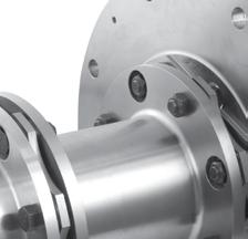
8 Rexnord Thomas Flexible Disc s Close-Coupled Series 54RDG Series 54RDG couplings are reduced diameter gear and grid replacement couplings. Applications include any situation where the overall shaft-to-shaft spacing is minimal. The center member of the 54RDG is split axially, which permits maintenance of the couplings without moving the hubs or the connected equipment. Center member is piloted into the adapter providing high-speed potential at high-torque density. Construction Hubs and Center members: Carbon steel Bolts: Alloy steel Disc Packs: Stainless steel Coatings Available: Consult Rexnord Other disc pack materials such as Tomaloy, Monel and Inconel are available; please consult Rexnord. Misalignment: 1 /3 per disc pack When specified, Series 54RDG couplings meet all requirements of API 610 or API 671. If application requires API specification, please consult Rexnord. General Dimensions Bore* Internal Bore* External A B C C1 ** F F1 ** H N G C2 *** F2 *** * Uses Series 52 hubs. Non-bored hubs available upon request. ** Hubs may be reversed for alternate shaft spacing. *** Both hubs reversed. Kilowatt Per 100 RPM Service Factor 1.0 Not Balanced RPM Balanced Continuous Peak Overload (kg-m 2 ) Axial Capacity ,600 10, ± ,200 9, , ± ,800 8,600 1,185 2, ± ,700 8,400 1,976 3, ± ,600 7,400 3,706 7, ± ,000 6,700 5,803 11, ± ,800 6,200 7,552 15, ± ,500 5,800 11,323 22, ± ,300 5,400 15,161 30, ± ,200 5,000 16,979 33, ± ,000 4,600 27,817 55, ± ,900 4,200 37,300 74, ± ,800 3,900 48,973 97, ± ,700 3,600 76, , ± ,550 3,400 94, , ± ,450 3, , , ± ,350 3, , , ± ,300 2, , , ±3.96 See page 4 for explanation of RPM limits and balancing recommendations. and with standard length hubs, maximum bore and standard C. All Thomas disc couplings meet NEMA frame sleeve bearing motor specifications without modifications or the addition of end-float restricting devices. 8 (Catalog #2000M) NOTE: Dimensions subject to change. Certified dimensions of ordered material furnished on request.

9 Thomas Flexible Disc s Close-Coupled Series 54RD Series 54RD couplings are specifically designed as replacements for close-coupled gear and grid couplings, and where overall shaft-to-shaft spacing is minimal. Materials of construction are identical to the Series 52. Stainless steel disc packs are supplied as standard. To reduce maintenance costs, the Series 54RD is furnished with an axially split center member. This design permits the removal of the disc packs without moving the connected equipment. When specified, and based on speed requirements, the Series 54RD can be manufactured to meet API 610. If application requires API specification, please consult Rexnord. General Dimensions Max Bore* Internal Max Bore* External A B C C1** F F1** H N G C2*** F2*** * Non-bored hubs available upon request. ** Hubs may be reversed for alternate shaft spacing. *** Both hubs reversed. NOTE: When hub is used with barrel positioned outside of spacer, a Series 52 hub is used. Kilowatt Per 100 RPM Service Factor 1.0 Not Balanced RPM Balanced Maximum Continuous Peak Overload (kgm 2 ) Axial Capacity ,600 7, ± ,200 7, ± ,800 6, , ± ,700 6,000 1,208 2, ± ,600 5,500 1,976 3, ± ,000 5,000 2,743 5, ± ,800 4,500 3,850 7, ± ,500 4,000 5,769 11, ± ,300 3,700 8,162 16, ± ,200 3,400 9,280 18, ± ,000 3,300 13,999 27, ± ,900 2,800 24,272 48, ± ,800 2,500 30,368 60, ± , ,061 78, ± ,550 2,200 52, , ± ,450 2,100 65, , ± ,350 1,950 80, , ± ,300 1, , , ± ,200 1, , ,520 1, ±4.36 For larger sizes, consult Rexnord. All Thomas disc couplings meet NEMA frame sleeve bearing motor specifications without modifications or the addition of end-float restricting devices. and at maximum bore. For higher speeds, consult Rexnord. NOTE: Dimensions subject to change. Certified dimensions of ordered material furnished on request. (Catalog #2000M) 9
10 Rexnord Thomas Flexible Disc s Close-Coupled Types DBZ, DBZ-A, DBZ-B The standard DBZ coupling has two hubs inverted inside the disc pack and is used where overall shaft to shaft spacing is minimal. DBZ style has both hubs with inverted orientation. DBZ-A style has one hub extended to permit taper boring. DBZ-B style has both hubs extended to allow for greater spacing where required. Construction Hubs and Center Assembly: Carbon steel Bolts: Alloy steel Disc Packs: Tomaloy Coatings Available: Consult Rexnord Other disc pack materials such as stainless steel, Monel and Inconel are available; please consult Rexnord. Misalignment: 1 /2 per disc pack General Dimensions DBZ DBZ-A (one standard and one extended hub)* DBZ-B (two extended hubs)* Standard Hub Bore Extended Hub Bore A B1 B2 C1 C2 C3 E F1 F2 F3 G P1 P2 T Kilowatts Per 100 RPM Service Factor 1.0 Not Balanced RPM Continuous Peak Overload (kg-m 2 ) Balanced DBZ DBZ-A DBZ-B DBZ DBZ-A DBZ-B ,000 9, ± ,000 8, ± ,000 7, ± ,000 7, ± ,500 6, ± ,000 6, ± ,600 5, ± ,100 5, ± ,700 4, ± ,300 4, ± ,900 4, ± ,700 3, ± ,600 3, ±3.91 All Thomas disc couplings meet NEMA frame sleeve bearing motor specifications without modifications or the addition of end-float restricting devices. and at maximum bore. * Extended hubs can be supplied with straight bores or taper bores. Axial Capacity 10 (Catalog #2000M) NOTE: Dimensions subject to change. Certified dimensions of ordered material furnished on request.
11 Notes NOTE: Dimensions subject to change. Certified dimensions of ordered material furnished on request. (Catalog #2000M) 11
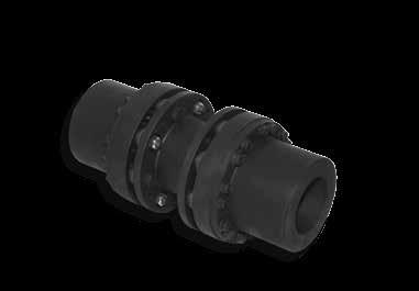
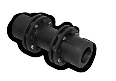
12 Rexnord Thomas Flexible Disc s Thomas XTSR52 Spacer Type Series with Optional Adapter Optimized design and construction include stainless disc packs and corrosion protection; additional modifications may be made to reduce coupling weight, or special mountings to make it an economical alternative to high performance styles. Common engineered solutions are available such as torque overload protection, electrically insulated, spark resistant, and alloy construction. An optional one size larger LH hub, two sizes larger XL hub, or three sizes larger XXL hub is available with adapter to increase bore capacity. The XTSR52 couplings are an all-purpose high-speed, high-torque coupling used where minimum coupling weight is desirable. The XTSR52 couplings are API 610, ISO 10441, ISO compliant when specified, and ATEX II 2GD c T6 certified. Common applications include motor and turbine driven pumps, compressors, fans, synchronized rollers, wire feeders and blowers. Construction Hubs and Center assembly: Carbon steel Bolts: Alloy steel Disc Packs: Stainless steel. Max misalignment is 1/2 per disc pack for sizes and 1/3 per disc pack for sizes Coatings Available: Manganese Phosphate provided as standard. Other coatings available upon request. WITHOUT ADAPTER WITH ADAPTER A G General Data Cont. (N m) ➄ Std Hub Bore LH Hub Bore XL Hub Bore XXL Hub Bore Min. C Min. C with Adapter C Speed (rpm) ➃ Not Balanced Balanced Axial Capacity N (kg m 2 ) ,000 20,000 ± ,900 18,500 ± ,800 15,000 ± , ,000 14,000 ± , ,000 12,000 ± , ,100 10,000 ± , ,600 9,100 ± , ,100 8,500 ± , ,800 7,800 ± , ,500 7,100 ± , ,200 6,500 ± , ,800 6,000 ± , ,600 5,700 ± , ,400 5,400 ± , ,200 4,700 ± , ,900 4,400 ± , ,800 4,100 ± , ,600 3,900 ± , ,400 3,600 ± , ,200 3,300 ± , ,100 3,100 ± A G N B C B STANDARD HUB (WITHOUT ADAPTER) N B C B1, B2 or B3 WITH ADAPTER AND LARGE HUB G1 or G2 or G3 Example Selection: 1. Select coupling size 1088 for 2000 Nm torque and 65mm pump shaft diameter. 2. Select XXL 2nd hub for 100mm motor shaft diameter. 3. Therefore, coupling is a 1088 XTSR52 XXL. A 1088 XTSR52 XXL has one hub with 65mm max bore and one hub with 110mm max bore. A1 or A2 or A3 Std A LH A1 XL A2 XXL A3 Std B 12 (Catalog #2000M) NOTE: Dimensions subject to change. Certified dimensions of ordered material furnished on request. LH B1 XL B2 XXL B3 Std G LH G1 XL G2 XXL G3 Std Change Per mm of C (kg/mm) All Thomas disc couplings meet NEMA frame sleeve bearing motor specifications without modification or the addition of end-float restricting devices. and of couplings without adapters at maximum bore and minimum C dimension listed. Consult Rexnord for minimum rough bore sizes. ➃ XTSR52 couplings meet AGMA Class 9 balance requirements as manufactured with interference fit bore and close fit keyway. If clearance fit and/or setscrews are required, consult Rexnord. ➄ Peak Overload (N m) is twice the Maximum Continuous.

13 Rexnord Thomas Flexible Disc s Thomas XTSR52 Spacer Type Series with Optional Adapter Component Part Numbers Standard Hub ➅ LH Hub + Cap Screw Kit ➅ XL Hub + Cap Screw Kit ➅ XXL Hub + Cap Screw Kit LH Part No. Adapters ➄ Inch Standard C Dimensions Metric Standard C Dimensions XL Part No. XXL Part No. 3.5" 4.375" 5.0" 7.5" 8.0" 9.0" 100mm 140mm 180mm 250mm Standard Center Member When Adapter Not Used Inch Standard C Dimensions When Adapter Used Metric Standard C Dimensions 4.375" 5.0" 7.5" 8.0" 9.0" 100mm 140mm 180mm 250mm Standard Center Member When Adapter Used (LH, XL, XXL) NOTE: Dimensions subject to change. Certified dimensions of ordered material furnished on request. ➃ Disc Pack Hardware Kit ➆ Adapter-Hub Capscrew Kit ➄ ➃ Disc Pack ➅ ➆ (Catalog #2000M) 13

14 Rexnord Thomas Flexible Disc s Thomas XTSR71 Spacer Type Series with Adapter The optimized 3-piece design allows for the smallest possible package for an application. The hubs are pilot fitted to the factory assembled center member. The design allows for repeatable installations without special tooling. Additional modifications may be made to reduce coupling weight, or special mountings to make it an economical option on various critical and high speed applications. Common engineered solutions are available such as torque overload protection, electrically insulated, spark resistant and alloy construction. The XTSR71 couplings are designed for spacer type coupling critical applications including API applications. The XTSR71 couplings are API 610 and ISO compliant, API 671 (ISO 10441) when specified, and ATEX II 2GD c T6 certified. Common applications include motor and turbine driven pumps, compressors, fans, synchronized rollers, wire feeders and blowers. Construction Hubs and Center assembly: Carbon steel Bolts: Alloy steel Disc Packs: Stainless steel. Max misalignment is 1/2 per disc pack for sizes 726 to 996 and 1/3 per disc pack for sizes 1088 to Coatings Available: Manganese Phosphate provided as standard. Other coatings available upon request. General Data Cont. (N m) ➄ Std Hub Bore XL Hub Bore XXL Hub Bore Min. C C Speed (rpm) ➃ Not Balanced Balanced Axial Capacity Max Counter Bore E ,000 20,000 ± ,900 18,500 ± ,800 15,000 ± , ,000 14,000 ± , ,000 12,000 ± , ,100 10,000 ± , ,600 9,100 ± , ,100 8,500 ± , ,800 7,800 ± , ,500 7,100 ± , ,200 6,500 ± , ,800 6,000 ± , ,600 5,700 ± , ,400 5,400 ± , ,200 4,700 ± , ,900 4,400 ± , ,800 4,100 ± , ,600 3,900 ± , ,400 3,600 ± , ,200 3,300 ± , ,100 3,100 ± A2 G2 or or MAX A3 G3 BORE LARGE HUB KEYWAY STANDARD HUB KEYWAY B2 or B3 C B MAX BORE E G A Std A XL A2 XXL A3 Std B XL B2 XXL B3 Std G All Thomas disc couplings meet NEMA frame sleeve bearing motor specifications without modification or the addition of end-float restricting devices. and of couplings with standard adapters at maximum bore and minimum C dimension listed. Consult Rexnord for minimum rough bore sizes. ➃ XTSR71 couplings meet AGMA Class 9 balance requirements as manufactured with interference fit bore and close fit keyway. If clearance fit and/or setscrews are required, consult Rexnord. ➄ Peak Overload (N m) is twice the Maximum Continuous. XL G2 XXL G3 Std Change Per mm of C (kg/mm) (kg m 2 ) Example Selection: 1. Select coupling size 1088 for 2000N m torque and 65mm pump shaft diameter. 2. Select XXL 2nd hub for 100mm motor shaft diameter. 3. Therefore, coupling is a 1088 XTSR71 XXL. A 1088 XTSR71 XXL has one hub with 76mm max bore and one hub with 110mm max bore. 14 (Catalog #2000M) NOTE: Dimensions subject to change. Certified dimensions of ordered material furnished on request.


15 Rexnord Thomas Flexible Disc s Thomas XTSR71 Spacer Type Series with Adapters Component Part Numbers Standard Hub + Cap Screw Kit XL Hub + Cap Screw Kit Standard Adapter XL Adapter XXL Adapter Inch Standard C Dimensions Metric Standard C Dimensions 3.5" 4.375" 5.0" 7.0" 7.5" 8.0" 9.0" 100mm 140mm 180mm 250mm Standard Center Member STD, XL, XXL ➃ Adapter Hub Capscrew Kit ➄ Disc Pack Hardware Kit ➅ Disc Pack ➄ ➅ ➃ Reference ➃ Reference ➄ NOTE: Dimensions subject to change. Certified dimensions of ordered material furnished on request. (Catalog #2000M) 15
 at Min dw at Max dw ØD Tollok Data L 30 24 26 300 380 60 21.5 0.")
16 Rexnord Thomas Flexible Disc s Tollok TLK 603 External Shrink Disc Standard Version Characteristics Medium-high torque No shaft-hub axial movement Limited installation time Quick dismantling L ø D ø dw ø d TLK 603 shown mounted on separately sold XTSR71 coupling. TLK 603 Tollok TLK 603 Ød Min Shaft O.D. Ødw Max Continous (N m) at Min dw at Max dw ØD Tollok Data L , ,160 1, ,850 2, ,000 3, ,500 3, ,200 4, ,800 7, ,750 7, ,900 9, ,200 10, ,400 11, ,600 14, ,000 15, ,300 15, ,100 20, ,000 28, ,600 28, ,000 39, ,900 40, ,000 45, ,000 46, ,000 62, ,500 63, ,000 81, ,000 86, , , , , Identified selections meet minimum bore, maximum bore and are equal to or greater than coupling size peak overload torque rating. XTSR Available In These s 16 (Catalog #2000M) NOTE: Dimensions subject to change. Certified dimensions of ordered material furnished on request.
17 Notes NOTE: Dimensions subject to change. Certified dimensions of ordered material furnished on request. (Catalog #2000M) 17

 Coatings Available: Consult Rexnord Other disc pack")
18 Rexnord Thomas Flexible Disc s Type AMR AMR couplings are used in heavy-duty, slow to medium speed applications, where high-starting torque, shock loads, torque reversals or continuous alternating torque are present. The open lug type center member provides ample clearance for assembly while minimizing the space required for coupling installation. Construction Hubs: s are carbon steel with integral washer, sizes 600 and larger are carbon steel with separate grooved washer. Center Member: s are cast alloy iron, sizes 800 and larger are cast steel Bolts: Alloy steel Disc Packs: Tomaloy Tpack (sizes ) Coatings Available: Consult Rexnord Other disc pack materials such as stainless steel, Monel and Inconel are available; please consult Rexnord. Misalignment: 1/3 per disc pack General Dimensions ➃ Rough Bore ➅ Bore A B C F G Kilowatt per 100 RPM Service Factor 1.0 RPM Continuous ➆ Peak Overload ➄ (kg-m 2 ) , ± ,500 1,245 1, ± ,500 1,758 2, ± ,500 2,375 2, ± ,500 2,670 3, ± ,300 5,961 7, ± ,200 8,968 10, ± ,000 9,935 11, ± ,900 15,367 18, ± ,800 22,663 27, ± ,800 31,052 37, ± ,800 40,514 48, ± ,500 51,535 61, ± ,500 72,808 87, ± ,200 91, , ± , , , ± , , , ± , , ±4, , ,173 1, ±4, , ,334 1, ±5, , ,369 1, ±5, , ,211 2, ±6,14 All Thomas disc couplings meet NEMA frame sleeve bearing motor specifications without modification or the addition of end-float restricting devices. and at maximum bore. Consult Rexnord if balancing is required. ➃ Consult Rexnord for minimum rough bore on size ➄ Special hub available for size 600 with 6 ¾ max. bore. Consult Rexnord. ➅ Straight bores with no keyway require a special material hub. Consult Rexnord. ➆ The peak overload torque is not an alternating torque limit. Axial Capacity 18 (Catalog #2000M) NOTE: Dimensions subject to change. Certified dimensions of ordered material furnished on request.

19 Rexnord Thomas Flexible Disc s Flywheel Adapter Type CMR CMR couplings are used in heavy-duty, slow to medium speed applications, where high-starting torque, shock loads, torque reversals or continuous alternating torque are present. The open lug type center member provides ample clearance for assembly while minimizing the space required for coupling installation. The CMR couplings are designed with a flywheel adapter plate which bolts directly to the flywheel of an engine or compressor. The adapters are made to fit accurately into the recess in the flywheel, and external strains on the crankshaft resulting from the misalignment of the driven equipment is minimized. Construction Hubs: s are carbon steel with integral washer, sizes 600 and larger are carbon steel with separate grooved washer. Center Section: s are cast alloy iron, s 800 and above are cast steel Bolts: Alloy steel Disc Packs: Tomaloy Tpack ( size) Coatings: Consult Rexnord Other disc pack materials such as stainless steel, Monel and Inconel are available; please consult Rexnord. Misalignment: 1/3 per disc pack Flywheel Adapter Information Adapters can be furnished to accommodate virtually any flange design. Where possible, the user should select dimensions from the tables below, as these represent industry standards and thus are the most economical selection. Note that most sizes are available either with SAE bolting or Thomas heavy-duty bolting. Available Adapters Adapter Tolerance Bolting Standard A Diameter Bolt Circle Light-Duty SAE Bolting No. Holes Hole Dia. Bolt Circle Adapters Available in Shaded s s 925 to Adapting dimensions available upon request. NOTE: values are metric conversions of standard SAE Inch adapter diameters. Heavy-Duty Thomas Bolting No. Holes Hole Dia Available In These s NOTE: values are metric conversions of standard SAE Inch series diameters, bolt circle diameters and bolt holes. NOTE: Dimensions subject to change. Certified dimensions of ordered material furnished on request. (Catalog #2000M) 19
20 Rexnord Thomas Flexible Disc s Flywheel Adapter Type CMR General Dimensions ➆ Rough Bore Bore Min. A Dia. B C D E F G , , , , , , , , , , , , , , , , , , , , , , , , , , , , , , , , , , , , , , , , , , , Kilowatt per 100 RPM Service Factor 1.0 RPM Continuous ➇ Peak Overload ➄ ➅ All Thomas disc couplings meet NEMA frame sleeve bearing motor specifications without modification or the addition of end-float restricting devices. Straight bores with no keyway require special material. Maximum speeds are based on smallest available adapter O.D. For higher speeds, consult Rexnord. ➃ Flywheel bolts are not supplied with coupling. ➄ and at maximum bores and minimum adapter diameter. ➅ Special hub available for size 600 with 6.75 in. max. bore. Consult Rexnord. ➆ Consult Rexnord for minimum rough bore on sizes ➇ The peak overload torque is not an alternating torque limit. ➄ (kg-m 2 ) Axial Capacity , ,005 ± ,500 1,245 1, ,017 ± ,500 1,758 2, ,022 ± ,500 2,375 2, ,047 ± ,500 2,670 3, ,107 ± ,300 5,961 7, ,193 ± ,200 8,968 10, ,300 ± ,200 9,935 11, ,465 ± ,900 15,367 18, ,658 ± ,800 22,663 27, ,241 ± ,800 31,052 37, ,113 ± ,800 40,514 48, ,511 ± ,500 51,535 61, ,671 ± ,500 72,808 87, ,919 ± ,200 91, , ,269 ± , , , ,121 ± , , , ,845 ± , , ,645 ±4, , , ,272 ±4, , , ,088 ±5, , , ,904 ±5, , , ,784 ±6,14 20 (Catalog #2000M) NOTE: Dimensions subject to change. Certified dimensions of ordered material furnished on request.

21 Rexnord Thomas Flexible Disc s Type BMR Type BMR couplings are recommended for heavy-duty motor and engine driven service such as paper machines, grinding mills, dredges, and marine propulsion. The BMR uses a solid intermediate shaft which can be furnished complete by Rexnord or fabricated by the user. Hubs are carbon steel, shafting is hot or cold-rolled steel, and disc packs are Tomaloy Tpack ( sizes, stainless steel also available). Misalignment: 1/3 per disc pack. General Dimensions Rough Bore ➃ Bore A B C F G Kilowatt per 100 RPM Service Factor 1.0 RPM Continuous Peak Overload (kg-m 2 ) Axial Capacity , ±0, ,800 1,245 1, ±0, ,800 1,758 2, ±0, ,800 2,375 2, ±1, ,800 2,670 3, ±1, ,800 5,961 7, ±1, ,800 8,968 10, ,470 ±1, ,800 9,935 11, ,320 ±1, ,500 15,367 18, ,085 ± ,500 22,663 27, ,500 ± ,500 31,052 37, ,850 ± ,200 40,514 48, ,700 ±2.59 BMR Shafting Selection Table Shaft Diameter Kw/100 for Given Shaft Dia. Allowable Shaft Wt. Span at Allow Shaft Wt. Span For Various RPM All Thomas disc couplings meet NEMA frame sleeve bearing motor specifications without modifications or the addition of end-float restricting devices. and at maximum bore and minimum L. Consult Rexnord for minimum rough bore on sizes ➃ Straight bores with no keyway require special material. NOTE: Dimensions subject to change. Certified dimensions of ordered material furnished on request. (Catalog #2000M) 21
22 Rexnord Thomas Flexible Disc s Series 44 Flywheel Adapter Type The Series 44 is an all-steel fully machined flywheel adapter style coupling. It is used in heavy-duty applications where high starting torque, shock loads, torque reversals or alternating torques are present. This coupling is similar to the type CMR, but with the following benefits: Dimension C and spool are adjustable to meet specific spacing requirements and/or to make adjustment to torsional characteristics. The all-steel design provides a higher maximum continuous and peak overload torque rating. Fully-machined components offer a higher operating speed and balancing level. Construction Hubs and Center Assembly: Carbon Steel Bolts: Alloy Steel Disc Packs: Tomaloy Tpack ( ) Coatings Available: Black Oxide, Zinc, Cadmium Other disc pack materials such as stainless steel, Monel and Inconel are available; please consult Rexnord. Misalignment: 1/3 per disc pack When specified, Series 44 couplings meet all requirements of API 610 or API 671. If application requires API specification, please consult Rexnord. General Dimensions Bore Min. A Dia. B Std. C Min. C D E F (Ref.) G N A ➃ ➄ Kilowatt Per 100 Service Factor 1.0 Not Balanced RPM Balanced Continuous ➃ Peak Overload ➄ Change Per mm of C ➄ (kg-m 2 ) Change Per mm of C (kg-m 2 ) Axial Capacity ,200 10,500 6,562 13, ± ,000 9,400 9,604 19, ± ,800 8,700 10,677 21, ± ,700 8,100 15,380 30, ± ,500 7,100 22,682 45, ± ,300 6,300 35,187 70, ± ,150 5,700 44,440 88, ± , , , ± ,850 4,600 73, , ± ,750 4,300 98, , ± ,600 3, , , ± ,500 3, , , ± ,500 3, , , ±4.36 Thomas disc couplings meet NEMA MG , , & specifications without the addition of end-float restricting devices. Flywheel fasteners are not supplied with this coupling. Contact equipment manufacturer for this hardware and tightening instructions. Maximum speeds are based on use with all standard available adapters. For larger sizes or higher speeds, please consult Rexnord. The peak overload torque rating is an infrequent torque overload limit and not an alternating or vibratory torque limit. and values are based on maximum bores and minimum adapter diameters listed above. 22 (Catalog #2000M) NOTE: Dimensions subject to change. Certified dimensions of ordered material furnished on request.

23 Rexnord Thomas Flexible Disc s Series 44 Flywheel Adapter Type Flywheel to Adapter Bolt Patterns Standard A Diameter Bolt Circle Light-Duty SAE Bolting No. Holes Hole Dia. Bolt Circle Heavy-Duty Thomas Bolting No. Holes Hole Dia N/A N/A N/A All dimensions listed are in millimeters and bolt holes are equally spaced. NOTE: values are metric conversions of standard SAE inch series diameters, bolt circle diameters and bolt holes. Flywheel Adapter Information* Adapters can be furnished to accommodate most flange designs. Where possible, the user should select dimensions from the tables shown, as these represent industry standards that are more economical and readily available. Note that most sizes can be supplied with either SAE light-duty bolting or Thomas heavy-duty bolting. Please contact Rexnord for custom designs. Minimum Adapter A Dia Standard Available Adapter Diameters - Actual OD Tolerance as Listed WT. = 1.76 = Wt. = 0.69 = Wt. = 3.75 = Wt. = 2.91 = Wt. = 1.27 = Wt. = 6.95 = Wt. = 6.49 = Wt. = 5.22 = Wt. = 2.67 = Wt. = 0 = 0 Wt. = = Wt. = = Wt. = = Wt. = 8.35 = Wt. = 6.17 = Wt. = 1.21 = Wt. = 0 = 0 Wt. = = Wt. = = Wt. = = Wt. = = Wt. = = Wt. = 8.08 = Wt. = 7.81 = Wt. = 0 = 0 Wt. = = Wt. = = Wt. = = Wt. = = Wt. = = Wt. = = Wt. = = Wt. = 9.22 = Wt. = = Wt. = = Wt. = = Wt. = = Wt. = = Wt. = = Wt. = 5.77 = No industry standards exist for adapters to fit couplings this size or larger. Consult Rexnord. * adder values are given in kg. values are given in kg-m 2. Wt. and is zero if the listed minimum adapter A diameter is the same as complete coupling calculated values in general dimension tables on page 18. NOTE: Add Wt. and values listed in table to the weight and inertia values provided on page 18 for given size to calculate actual values based on selected adapter size. Wt. = = Wt. = = 4.22 Wt. = = Wt. = = Wt. = = Wt. = = Wt. = = Wt. = 0 = 0 NOTE: Dimensions subject to change. Certified dimensions of ordered material furnished on request. (Catalog #2000M) 23

24 Rexnord Thomas Flexible Disc s Type SN-GA Replaces troublesome gear couplings on pulp and paper applications. The Thomas one-piece, factory-torqued assembly is easy to install. This coupling is designed to bolt directly to existing rigid hubs using the gear coupling bolts. Axial shims are supplied for minor axial positioning adjustment. Construction Hubs and Center Assembly: Carbon steel Bolts: Alloy steel Disc Packs: Stainless Tpack Coatings Available: Consult Rexnord Other disc pack materials such as Tomaloy, stainless steel, Monel and Inconel are available; please consult Rexnord. Misalignment: 1/3 per disc pack Available Adapters Gear (Falk) Thomas #1½ (1015) #2 (1020) #2½ (1025) T 550T 600T 700T 750T 800T 850T For other sizes, please consult Rexnord. #3 (1030) #3½ (1035) #4 (1040) #4½ (1045) Available In These s #5 (1050) #5½ (1055) #6 (1060) #7 (1070) Kilowatt per 100 RPM Service Factor 1.0 Continuous Peak Overload A L Min. MD ± ± ± ± ± ± ± T ± T ± T ± T ± T ± T ± T ±3.65 All Thomas disc couplings meet NEMA frame sleeve bearing motor specifications without modification or the addition of end-float restricting devices. The peak overload torque is not an alternating torque limit. Available with Tpack for new couplings, not retrofittable in size 450. N Axial Capacity 24 (Catalog #2000M) NOTE: Dimensions subject to change. Certified dimensions of ordered material furnished on request.

25 Rexnord Thomas Flexible Disc s Floating Shaft Types SN, SF, SV Floating shaft couplings are used to connect units which are relatively far apart. Such arrangements are particularly suited to transmit power into areas where moisture, dust or corrosive conditions would adversely affect the driving machinery. Floating shaft couplings operating speeds are dependent upon the length of span required. Refer to the speed/span table for speed recommendations. In addition, special balancing may be required for high-speed service or for extended shaft lengths. Consult Rexnord for intended applications at speeds not covered in the table. The SN, SF and SV type couplings are furnished with stainless steel disc packs unless otherwise specified. Type SN Full-Floating Shaft Type SN couplings use a tubular center shaft, fabricated complete by Rexnord. Typical applications include cooling tower fan drives, paper machinery, printing presses, pumps and compressors. Connected shafts should be rigidly supported and long shaft overhang should be avoided. The tubular coupling shaft MUST NOT be supported with a bearing. They may be operated vertically if length does not exceed 36 in. Type SF Semi-Floating Shaft Type SF couplings are a tubular shaft design with a stub shaft and bearing journal replacing the half-coupling on one end. They are typically used in tandem with the Type SN or Type SV where spans are too long for a single section of shafting. Type SV Vertical Floating Shaft s Type SV couplings are similar to the Type SN except that the lower half-coupling is modified to support the weight of the floating shaft. Typical applications include fresh-water pumps, sewage pumps, and marine cargo pumps. They may be used in tandem with the Type SF where spans are too long for a single shaft. Corrosion Resistant Materials Types SN, SV and SF couplings are particularly suited to applications involving wet or corrosive conditions, for this reason they are all furnished with 300 series stainless steel disc packs. For extremely corrosive environments, 316 stainless steel, Inconel 625 or Monel disc pack materials are available on request. As standard, these couplings are available in the following material classes. NOTE: The stub shaft on the SF coupling is always furnished as unplated carbon steel in classes A, B, C and D. s may be painted with acid and alkali resistant paints or coating besides the corrosion resistant classes listed. CLASS A All steel B All steel zinc plated C All steel zinc plated w/stainless steel hardware D Stainless steel except for zinc plated hubs E All 300 series stainless steel Floating Shaft s Types SN, SV and SF center members are of tubular construction, requiring special considerations for the operating speed and span length. The graph to the right may be used as a guide when determining whether it is desirable to balance the center member. The standard procedure for balancing of SN, SV and SF couplings includes straightening of the tubular shaft prior to balancing. Many couplings of this type operate relatively near to the lateral resonant frequency of the coupling center member, and special balancing techniques are often required. For speeds 1800 RPM and under see page 4 for balancing recommendations. Consult Rexnord for any application with speed in excess of 1800 RPM. NOTE: Dimensions subject to change. Certified dimensions of ordered material furnished on request. (Catalog #2000M) 25
26 Rexnord Thomas Floating Shaft Types SN, SF, SV General Dimensions ➄ Type Bore A B D E Min. L F G N NL SIze SN SV SF ➇ T U SN SF * * T T T T T T T T ➄ Continuous Peak Overload ➃ Change Per mm of L ➃ (kg-m 2 ) All Thomas disc couplings meet NEMA frame sleeve bearing motor specifications without modification or the addition of end-float restricting devices. Shorter L requires special construction. Consult Rexnord. Shaft tolerances: 5/16 to 1-1/ /8 to 3-11/ Key furnished with standard keyway in SF stub shaft. ➃ and at max. bore and min. L dimension. ➄ T suffix to coupling size indicates thin flange design. Consult Rexnord for larger sizes. ➅ Types SF and SV end-float is one half ± value shown for type SN. ➆ Maximum span (L) in inches for various speeds - For SN & SV ➇ Consult Rexnord for larger sizes. *Not available with Tpack. 26 (Catalog #2000M) NOTE: Dimensions subject to change. Certified dimensions of ordered material furnished on request. Change Per mm of L (kg-m 2 -m) ➅ Type SN Axial Capacity SN, SV SF SN, SV SF ± ± ± ± ± ± ± * ± ± ± ± ± ± * ± T ± T ± T ± T ± T ± T ± T ± T ±3.96
27 Rexnord Thomas Floating Shaft Types SN, SF, SV Maximum Span at Given RPM 3600 RPM 3000 RPM 1800 RPM 1500 RPM 1200 RPM 1000 RPM 900 RPM 750 RPM 720 RPM 600 RPM 500 RPM 50 Consult Rexnord * T T T T T Consult T Rexnord Consult 850T 925T Rexnord * Not available with Tpack Type SN Adjustable Type SN adjustable couplings were developed as emergency replacements for standard Type SN couplings and are available from stock in most sizes required for cooling tower applications. Each shaft may be adjusted through a four-inch length range, using a special compression bushing to lock the shaft in place once the length is set. General Dimensions Bore A B G H Min. L Adjustment Range Change Per mm of L (kg-m 2 ) Change per mm of L (kg-m 2 ) Axial Capacity ± ± ± ±1.09 All Thomas disc couplings meet NEMA frame sleeve bearing motor specifications without modification or the addition of end-float restricting devices. and at maximum bore. NOTE: Dimensions subject to change. Certified dimensions of ordered material furnished on request. (Catalog #2000M) 27
28 Rexnord Thomas Single-Flexing Disc s Type ST ST couplings are designed for applications which require the coupling to support a substantial radial load while accommodating angular misalignment. Typical installations include units where one shaft is fully supported in its own bearings and the other shaft is single-bearing supported. The radial load is transmitted through the coupling to the inner bearing of the other shaft. Belt drives can be designed to utilize this type of coupling to eliminate a jack shaft bearing and transfer radial loading directly to a machine bearing. Such arrangements are economical and space saving. See the sketches to the right. Construction Hubs: Carbon steel Bolts: Alloy steel Disc Packs: Tomaloy Tpack not available Coatings Available: Contact Rexnord. Other disc pack materials such as stainless steel, Monel and Inconel are available; please consult Rexnord. NOTE: Single-flexing couplings cannot accommodate parallel misalignment. They are not suitable for connecting equipment where both shafts are held rigidly in their own bearings. General Dimensions ➆ Rough Bore Bore A B F G N Radial Load Smooth Kilowatt per 100 RPM Pulsating Col. 1 ➃ Col. 2 ➄ Col. 3 Col. 4 ➃ Col. 5 ➄ Col. 6 RPM ➅ Continuous ➅ Peak Overload (kg-m 2 ) , ± , ± , ± , ± , , ± ,300 1,089 1, ± ,200 1,683 2, ± ,900 2,181 3, ± ,500 2,779 4, ± ,500 4,293 6, ± ,500 6,191 9, ± ,200 8,756 13, ± ,100 13,558 20, ± ,000 17,851 26, ± ,596 33, ±1.72 All Thomas disc couplings meet NEMA frame sleeve bearing motor specifications without modification or the addition of end-float restricting devices. and at maximum bore. Col. 1 and 4 give maximum HP/100 RPM permitted when combined with maximum radial load. ➃ Col. 2 and 5 give maximum HP/100 RPM permitted when combined with 2/3 maximum radial load. ➄ Col. 3 and 6 give maximum HP/100 RPM permitted when combined with 1/3 maximum radial load. ➅ Maximum torque and peak overload torque are based on 1/3 maximum radial load. ➆ Consult Rexnord for minimum rough bore on sizes Axial Capacity 28 (Catalog #2000M) NOTE: Dimensions subject to change. Certified dimensions of ordered material furnished on request.

29 Rexnord Thomas Single-Flexing Disc s Type SN Single Type SN single couplings are used for floating shaft applications where the user wishes to supply his own intermediate solid shaft, or for single-flexing applications where light-tomoderate radial loads occur. They are generally more economical than ST couplings. Construction Hubs: Carbon steel Bolts: Alloy steel Disc Packs: Tomaloy Tpack (not available for size 450) Coatings Available: Consult Rexnord Other disc pack materials such as stainless steel, Monel and Inconel are available; please consult Rexnord. Misalignment: 1/3 per disc pack NOTE: Single-flexing couplings cannot accommodate parallel misalignment. They are not suitable for connecting equipment where both shafts are held rigidly in their own bearings. General Dimensions Bore A B F G N T T T T T Type SN Single Kilowatt Per 100 RPM Service Factor 1.0 RPM Continuous Peak Overload (kg-m 2 ) Axial Capacity , ± , ± , ± , ± , ± , ± ,500 5, ± ,100 7, ± ,900 11, ± ,700 15, ± ,600 16, ± T 292 2,800 27, ± T 391 2,500 37, ± T 513 2,300 48, ± T 799 2,000 76, ± T 992 1,800 94, ±1.58 All Thomas disc couplings meet NEMA frame sleeve bearing motor specifications without modification or the addition of the end-float restricting devices. Consult Rexnord for minimum rough bore on sizes and shown at maximum bore. NOTE: Dimensions subject to change. Certified dimensions of ordered material furnished on request. (Catalog #2000M) 29

30 Rexnord Thomas Flexible Disc s High Performance THP THP couplings are designed for use on high-speed equipment where coupling size and weight must be kept to a minimum. Typically, these couplings connect prime movers such as motors, steam and gas turbines, rotary engines and gas expanders, to centrifugal and rotary compressors, generators, process and boiler feed pumps. Test stand and marine propulsion drives also benefit from this unique coupling design. The flexing elements are precision-stamped from a high-strength 300 series stainless steel. This material has been used successfully for many years in Thomas couplings manufactured for helicopter drive shaft applications. Special materials for hubs, spacers and/or flexing elements are available to meet unique application requirements. Construction Hubs and Center Member: Heat treated 4140 and 4340 alloy steel Bolts: Aircraft quality alloy steel with 12-point wrenching pattern Disc Packs: High strength 300 series stainless steel Coatings Available: Black oxide, zinc, cadmium and other coatings available per customer specification. Other disc pack materials such as Monel and Inconel are available; please consult Rexnord. General Dimensions A B C D E F G Bore Hydraulic H L M N Standard Bore ➃ Continuous Rating Speed RPM ➄ ➄ (kg-m 2 ) ➄ Half C.G. ➄ Torsional Stiffness Kt x 10 6 (Nm/Rad) Kt x 10 6 (Nm/Rad) Spacer Tube Per Inch (kg-m 2 ) ➅ Axial Capacity Continuous , ± , ± , ± , ± , ± , ± , ± , ± , ± , ± , ± , ± , ±5.21 For larger bores, consult Rexnord. May be reduced for smaller shaft sizes. Consult Rexnord. Minimum service factor to be applied = 1.5 ➃ peak overload torque = 1.33 x max. cont. torque ➄ Information based on standard dimensional data shown. ➅ transient axial misalignment = 120% of values shown above. 30 (Catalog #2000M) NOTE: Dimensions subject to change. Certified dimensions of ordered material furnished on request.

31 Rexnord Thomas Flexible Disc s High Performance Series 63 Series 63 couplings incorporate a patented* one-piece disc/diaphragm flexing element for positive torque transmission with low restoring forces. This unitized assembly accommodates misalignment and transmits torque through a multiple disc arrangement which provides redundancy in construction with a high degree of reliability. Pilot plates on the sides of each flexing element give accurate, repeatable registration of coupling components, and retain original dynamic balance repeatability while protecting the flexing members from damage. Series 63 couplings are ideal for the most demanding drive requirements. Prime movers include motor, steam and gas turbines, rotary engines, and gas expanders. Driven equipment applications include centrifugal and rotary compressors, generators, test stands, boiler feed pumps and other multi-stage pumps, and marine propulsion drives. Custom designs available for torsional tuning and reduced moment. *U.S. Patent Construction Hubs and Center Member: Heat-treated alloy steel Bolts: Alloy steel Disc Packs: High strength 300 series stainless steel Coatings Available: Consult Rexnord Other disc pack materials such as stainless steel, Monel and Inconel are available; please consult Rexnord. When specified, Series 63 couplings meet all requirements of API 671. If application requires API specification, please consult Rexnord. To determine Kt for a coupling with longer than standard C dimension, use the formula shown to the right: Where L = additional C dimension required Kt = torsional stiffness change per inch of C dimension and 1/Kt - inverse of catalog value. A G H E D K General Dimensions Bore A B B1 Min. C D E F Hydraulic H Keyed K Std. C G N Capacity ± ± ± ± ± ± ± ± ± ± ± ± ± ±4.82 B N C F B1 Dynamic Data ➃ Standard Mass-Elastic Data Speed RPM Continuous Peak Overload (kg-m 2 ) Kt x 10 6 (kg-mm/rad) C.G. Change per mm of C (kg-m 2 ) Kt x 10 6 (kg-mm/rad) , , ,600 1,537 3, ,700 2,384 5, ,500 4,271 10, ,100 7,242 18, ,200 9,253 23, ,600 14,236 35, ,300 19,094 47, ,300 24,066 60, ,600 35,703 89, ,300 51, , ,300 71, , , , , , , , Standard dimension - may be modified as necessary. G dimension at listed maximum bore and will vary depending on bore size. Consult Rexnord with higher speed requirements. ➃ and C.G. data based on standard C dimension, maximum hydraulic bores (H) and hydraulic hub lengths (B). Torsional stiffness (Kt) assumes a 1/3 shaft penetration factor. NOTE: Dimensions subject to change. Certified dimensions of ordered material furnished on request. (Catalog #2000M) 31

32 Rexnord Thomas Miniature s Thomas Miniature Flexible Disc s Construction Hubs and Center Member: Aluminum alloy, anodized Rivets: Brass Washers: Brass Discs: Stainless steel Set screws: 18-8 Stainless steel, Passivated Temperature: 250 F Available with electronically insulated phenolic material. Guide to Proper Designation of Hubs Style CC This coupling has both hubs inverted and is designed to fit shafts normally encountered at a given torque range. Ideal for use where space limitations require close coupling of the shafts. General Dimensions A B C F T Capacity capacities are based on smooth drives with moderate torque fluctuations. Reduce ratings to 1/3 the value shown for severe applications such as indexing drives where torque reversals occur. All Thomas disc couplings meet NEMA frame sleeve bearing motor specifications without modification or the addition of end-float restricting devices. Style CA This design of our miniature coupling has one inverted hub to accept a normal shaft and one extended hub to accommodate oversize shafts. It also accommodates a larger shaft gap than the Style CC. General Dimensions A B C F G T Capacity capacities are based on smooth drives with moderate torque fluctuations. Reduce ratings to 1/3 the value shown for severe applications such as indexing drives where torque reversals occur. All Thomas disc couplings meet NEMA frame sleeve bearing motor specifications without modification or the addition of end-float restricting devices. 32 (Catalog #2000M) NOTE: Dimensions subject to change. Certified dimensions of ordered material furnished on request.


33 Rexnord Thomas Miniature s Style CB & CBC This coupling design has both hubs extended to accept two oversized shafts. Shaft gap is larger than that of the Style CA or CC couplings. Style CBC is the newest addition to our miniature coupling line. It offers clamping hubs that are an integral part of the coupling. The clamping hubs assure positive fit on the shafts. There are no loose parts to handle during installation. The Style CBC coupling has the same dimensions and torque capacities as the Style CB. Consult Rexnord for additional design and engineering data. General Dimensions A B C F G Capacity Styles CC, CA, CB & CBC Ratings and Mass Elastic Data RPM Approx Approx (kg-m 2 ) Torsional Rigidity Kt x 10 3 (kg-mm/rad) Angular Misalignment Continuous Per Flexing Element Parallel Misalignment Continuous Axial Capacity , ± , ± , ± , ± , ± , ± , ± , ±0.78 and at maximum bore. All Thomas disc couplings meet NEMA frame sleeve bearing motor specifications without modifcation or the addition of end-float restricting devices. NOTE: Dimensions subject to change. Certified dimensions of ordered material furnished on request. (Catalog #2000M) 33

34 Rexnord Thomas Miniature s Style CE & CS The Style CE coupling consists of two Style CS single flexing couplings that are connected by a tubular shaft. It is designed to span large distances between shafts and is ideal for those applications where a large amount of parallel misalignment is anticipated. The Style CS is designed for applications where one shaft is fully supported in its own bearings and the other shaft is single-bearing supported. The single flexing design can only accept angular misalignment. General Data ➃ A B C F G L RPM Style CE Style CS Capacity CE CS Change Per Inch of L , , , Varies to suit as Consult 55, required Rexnord 45, , , , capacities are based on smooth drives with moderate torque fluctuations. Reduce ratings to 1/3 the value shown for severe applications such as indexing drives where torque reversals occur. calculated at maximum bore and L = 12". All Thomas disc couplings meet NEMA frame sleeve bearing motor specifications without modification or the addition of end-float restricting devices. ➃ For, misalignment capacities and torsional rigidity consult Rexnord. Standard Bore s for Style CC, CA, CB, CBC, CE & CS Miniature s Hub Inside Center Member , , , , , , , Bores (in) Hub Outside Center Member , , , , , , , , , Hub Inside Center Member , , , , , , , , Bores (in) Hub Outside Center Member , , , , , , , , , s not available with rough bore. Keyway not included in standard bore. Keyways and nonstandard bores also available. Tolerances: s 12 and 18, ±0.0003". Larger sizes, ±0.0005". The largest bore shown for each hub is maximum allowable bore. Consult Rexnord if a larger bore is required. 34 NOTE: Dimensions subject to change. Certified dimensions of ordered material furnished on request.
35 Rexnord Thomas s Rexnord Thomas Backstop Bolts directly to Thomas SN & TSN-CT hubs Prevents reverse shaft rotation of cooling tower fans All stainless steel construction For non-corrosive environments this can be supplied in carbon steel Bolt-On Backstop Tabulation Bore B.C. Dia Mating Hub Backstop Bolting Info Capscrew (Inch for capscrew dimensions) Min Tap DP Tight /4-20 NC x /4-20 NC x /4-20 NC x /8-16 NC x /16-14 NX x / /2-13 NC x OD W (Ref) Compressed Sprung Compressed Speed (RPM Ref) RPM Ref RPM Ref Special integral hub/backstop can be supplied. 162 & 200 size supplied with (4) socket head capscrews. All other sizes supplied with four hex head capscrews. Backstop may be inversely mounted for opposite rotation. NOTE: Dimensions subject to change. Certified dimensions of ordered material furnished on request. (Catalog #2000M) 35

36 Rexnord Thomas Flexible Disc s Spacer Type Series 52 - SEE PAGES FOR UPDATED VERSION WITH ENHANCED FEATURES Series 52 couplings are all-purpose high-speed, high-torque couplings used where minimum coupling weight is desirable. They are commonly used on motor and turbine driven pumps, compressors and fans. Design modifications may be made to further reduce the coupling weight, making it an economic alternative to high performance disc and diaphragm couplings. Construction Hubs and Center Assembly: Carbon Steel Bolts: Alloy Steel Disc Packs: Tomaloy Tpack ( ) Coatings Available: Black Oxide, Zinc, Cadmium Other materials such as stainless steel, Monel and Inconel are available; please consult Rexnord. Misalignment: 1/3 per disc pack When specified, Series 52 couplings meet all requirements of API 610 or API 671. If application requires API specification, please consult Rexnord. General Dimensions ➅ Bore A B Std. C Stocked C Min. C F G N Consult , , , 140, , , , , , , Taper Bores Also Available ➃ ➄ ➅ Kilowatt Per 100 RPM Service Factor 1.0 ➄ Not Balanced ➄ RPM Balanced Continuous Peak Overload All Thomas disc couplings meet NEMA frame sleeve bearing motor specifications without modification or the addition of end-float restricting devices. Additional C dimensions available. Consult Rexnord. Series 52 couplings meet AGMA Class 9 balance requirements as manufactured with interference fit bore and close fit keyway. If clearance fit and/or setscrews are required, please consult Rexnord. See page 4 for explanation of RPM limits and balancing recommendations. and at maximum bore and standard C dimension listed. Balance recommendations based on AGMA Specification 9000-C90 Average Sensitivity. Consult Rexnord for minimum rough bore sizes. ➃ Change Per mm of C ➃ (kg-m 2 ) Change Per mm of C (kg-m 2 ) ,000 15, ± ,600 15, , ± ,250 15,000 1,185 2, ± ,100 14,000 1,976 3, ± ,900 13,000 3,706 7, ± ,450 11,700 5,803 11, ± ,200 10,500 7,552 15, ± ,000 9,400 11,323 22, ± ,800 8,700 15,161 30, ± ,700 8,100 16,979 33, ± ,500 7,100 27,817 55, ± ,300 6,300 37,300 74, ± ,150 5,700 48,973 97, ± ,950 5,000 76, , ± ,850 4,600 94, , ± ,750 4, , , ± ,600 3, , , ± ,500 3, , , ± , , , ±4, , , , ±4, , , , ±5, , , , ±5,53 Axial Capacity 36 (Catalog #2000M) NOTE: Dimensions subject to change. Certified dimensions of ordered material furnished on request.


37 Rexnord Thomas Flexible Disc s Spacer Type Series 71 - SEE PAGES FOR UPDATED VERSION WITH ENHANCED FEATURES Series 71 couplings are designed for applications requiring a spacer-type coupling such as ANSI, API and other process pumps. Series 71 couplings are most commonly applied on motor, turbine, and gear driven pumps, compressors and blowers. Series 71 is a simple three-piece design. Three piece design features unitized center member assembly and two piloted hubs. Hubs are piloted fit to the factory assembled center member. The piloting provides repeatable assembly of components for better dynamic balance characteristics. The center assembly simply drops out for fast installation or removal without special tools. The disc design allows for low flexing forces and high overload capacity. Construction Hubs and Center Assembly: Carbon steel Bolts: Alloy steel Disc Packs: Stainless steel for 4- & 6-bolt designs Stainless steel Tpack for 8-bolt design Coatings Available: Black oxide, zinc, cadmium Other disc pack materials such as Monel and Inconel are available; please consult Rexnord. Misalignment: 1/2 per disc pack for 4- and 6-bolt designs, 1/3 per disc pack for 8-bolt design When specified, Series 71 couplings meet all requirements of API 610 or API 671. If application requires API specification, please consult Rexnord. Series 71 Balance Recommendations NOTE: These recommendations and balance classes are based on AGMA Specifications C90, high sensitivity. If conditions exist other than as defined in 9000-C90, for sensitivity, consult Rexnord. The above information should be used as a guide only. AGMA Class 9 balance is furnished as standard when Series 71 couplings are finished bored with interference fits. NOTE: Dimensions subject to change. Certified dimensions of ordered material furnished on request. (Catalog #2000M) 37
38 Rexnord Thomas Flexible Disc s Spacer Type Series 71 4-, 6- & 8-Bolt 4- & 6-Bolt Design 8-Bolt Design General Dimensions ➃ ➄ ➅ ➆ ➅ B&B 1 Hub Bore ➅ B&B 2 Hub Bore A B B1 4-Bolt Design Bolt Design Bolt Design Kilowatt Per 100 RPM Service Factor 1.0 ➄ Not Balanced ➃ RPM ➃ Balanced Continuous Peak Overload 38 (Catalog #2000M) NOTE: Dimensions subject to change. Certified dimensions of ordered material furnished on request. Std. B2 Std. C Change Per mm of C Min. C (kg-m 2 ) E Change Per mm of C (kg-m 2 -m) G Axial Capacity 4-Bolt Design ,000 20, ± ,300 17, ± Bolt Design ,700 16, ± ,800 14, , ± ,200 13,500 1,513 3, ± ,650 12,000 2,179 4, ± ,350 11,000 2,540 5, ± ,000 10,000 4,561 9, ± ,700 9,200 6,209 12, ± ,350 8,300 9,494 18, ± ,150 7,800 10,352 20, ± Bolt Design ,500 14,000 1,976 3, ± ,800 12,500 3,706 7, ± ,200 11,500 5,803 11, ± ,700 10,500 7,552 15, ± ,200 9,800 11,323 22, ± ,000 9,300 15,161 30, ± ,700 8,700 16,979 33, ± ,200 7,900 27,817 55, ± ,900 7,300 37,300 74, ± ,600 6,800 48,973 97, ± ,300 6,200 76, , ± ,100 5,800 94, , ±3.18 All Thomas disc couplings meet NEMA frame sleeve bearing motor specifications without modifications or the addition of end-float restricting devices. and with standard length hubs, maximum bore and standard C. Extended hub length is designed longer in order to include a counter-bore for the threaded extension on a tapered shaft. See page 4 for explanation of RPM limits and balancing recommendations. Series 71 assembly meets AGMA Class 9 Balance when finish bored with interference fits. Consult Rexnord for minimum rough bore sizes. If a block hub is supplied, extra capscrews will be provided for center member jacking feature.
39 Engineering Data All Rexnord s Recommended Hub Bores for Clearance & Interference Fit on Keyed Shafting Shaft Diameter Clearance Fit Transitional Fit Interference Fit Hub Bore Fit* Hub Bore Fit* Hub Bore Fit* j6 F H M MM +.008/ / / / / / / / / / / / / / / / / / / / j6 F H M MM +.009/ / / / / / / / / / / / / / / / / / / / / / / / / / / / / / / / >30 k6 F H K MM +.018/ / / / / / / / / / / / / / / / / / / / / / / / / / / / / / / / / / / / >50 m6 F H K MM +.030/ / / / / / / / / / / / / / / / / / / / / / / / / / / / / / / / / / / / / / / / >80 m6 F H M MM +.035/ / / / / / / / / / / / / / / / / / / / >100 m6 F7 H7 P MM +.035/ / / / / / / / / / / / >120 m6 F H P MM +.040/ / / / / / / / / / / / / / / / / / / / / / / / / / / / / / / / Shaft Diameter Clearance Fit Transitional Fit Interference Fit Hub Bore Fit* Hub Bore Fit* Hub Bore Fit* >180 m6 F H P7.125 MM +.046/ / / / / / / / / / / / >200 m6 F7 H7 R MM +.046/ / / / / / / / / / / / / / / / >225 m6 F7 H7 R MM +.046/ / / / / / / / / / / / / / / / >250 m6 F H R MM +.052/ / / / / / / / / / / / / / / / >280 m6 F7 H7 R MM +.052/ / / / / / / / / / / / / / / / / / / / >315 m6 F H R MM +.057/ / / / / / / / / / / / / / / / / / / / / / / / >355 m6 F7 H7 R MM +.057/ / / / / / / / / / / / / / / / / / / / / / / / >400 m6 F H R MM +.063/ / / / / / / / / / / / / / / / / / / / / / / / >450 m6 F7 H7 R MM +.063/ / / / / / / / / / / / / / / / / / / / / / / / NOTE: Consult Rexnord for all keyless bore fits. Taper-Lock and Q.D. Bushing Selection Cross Reference In order to cross reference tapered bushing and bore sizes to a coupling selection, the following tables will cover the majority of cases. Taper-Lock Type Bushing Bore DBZ and Type SV, SF, SN Series 52 Series 54RDG AMR, BMR, CMR, ST NOTE: C Dimension will be as listed for all couplings; F Dimension will vary according to bushing selection; Consult Rexnord for F dimensions and bushings. Hubs bored for Q.D. or Taper-Lock bushings will be modified for proper fit with bushing length. Consult Rexnord for s pecific dimensional data. If specific reference to the coupling series or type is not found in the table, i.e. special designs, comparison of the shaft size with the maximum bore table only, will indicate the correct taper bushing in the left side of each table. Other flange style and compression bushings can be used with coupling hubs. Q.D. Type Bushing Bore DBZ SV, SF, SN and Type Series 52 Series 54RDG Series 71 AMR, BMR, CMR, ST JA SH SDS SD SK SF E F With shallow keyway. Key supplied with bushing where shallow keyway is furnished. NOTE: Dimensions subject to change. Certified dimensions of ordered material furnished on request. (Catalog #2000M) 39
40 Rexnord Thomas s Customized Flexible Disc s Designs The following pages illustrate a sampling of the special disc coupling products designed and manufactured by Rexnord for applications requiring special coupling designs; please contact your Rexnord representative. SN-EL Extra Long Span Semi-Reduced Movement Bolt On Hub Torsionally Tuned Center Members Meter Electrically Insulated s Breaker Pin Bushing Style Breaker Pin Bearing Style Clamp Hub Mounting 40

41 Rexnord Thomas s Customized Flexible Disc s Designs Brake Drum Hub Motor-Tachometer Double Disc Packs AMR Bolt-On Inertia Ring Axial Limiting Stops Shrink Disc Hub Mounting Slide (Catalog #2000M) 41
Thomas Flexible Disc Couplings (Inch)
") Disc Catalog Download the most up-to-date version at www.rexnord.com/documentation Thomas Flexible Disc s (Inch) Table Of Contents DESCRIPTION PAGE Application Guide................................................................................................................
Disc Catalog Download the most up-to-date version at www.rexnord.com/documentation Thomas Flexible Disc s (Inch) Table Of Contents DESCRIPTION PAGE Application Guide................................................................................................................
Thomas Flexible Disc Couplings (Metric)
") Disc Catalog Download most up-to-date versions at www.rexnord.com Thomas Flexible Disc s (Metric) Table Of Contents DESCRIPTION PAGE Application Guide................................................................................................................
Disc Catalog Download most up-to-date versions at www.rexnord.com Thomas Flexible Disc s (Metric) Table Of Contents DESCRIPTION PAGE Application Guide................................................................................................................
Specialty Couplings. Overview. Deltaflex Coupling Design Lovejoy offers maximum misalignment capacity with the Deltaflex coupling! SP-3.
 Overview Deltaflex Coupling Design Lovejoy offers maximum misalignment capacity with the Deltaflex coupling! The Deltaflex coupling is the real solution to installation, misalignment, and performance problems.
Power Transmission Products. Maurey Couplings. Hi-Flex Tire Couplings Hi-Q Jaw Couplings Finished Bore Sleeve Couplings Rigid Bushed Sleeve Couplings
 Power Transmission Products Maurey Couplings Hi-Flex Tire Couplings Hi-Q Jaw Couplings Finished Bore Sleeve Couplings Rigid Bushed Sleeve Couplings Hi-Q Flexible Couplings R to enable full power transmission
Size 1120, Bore Ø0.75" Size 1320, Bore Ø1.25" Size 1420, Bore Ø1.375" 3/4HP. Size 1320, Bore Ø1.25" Size 1320, Bore Ø1.25" Size 1633, Bore Ø2.
 Product Range Hollow Shaft Type Selections shaded in blue offer an increased service factor. Please refer to the gearmotor selection tables for specific unit service factor details. Nominal Ratio (:1)
Gear Coupling. Applications
 Gear Coupling Applications Power Transformation Print & Paper Industries Gear Boxes Textile Industries Conveyors Pumps Compressors Process, Chemical & Pharmaceutical Industries Nylon Gear Couplings Nylon
Speed Reducers and Gearmotors
 and Gearmotors Table of Contents 1. General Information 2. How to Select...2.2 Configure a Model Number (Nomenclature)...2.4 AGMA Load Classifications...2.6...2.8 Single Reduction,,, Y3, Y5,...2.8 Single
Universal Joints. In This Section: D Type HD Type D Type Stainless NB (Needle Bearing) Type LOJ Type DD and DDX Type Universal Joint Boots
 Type LOJ Type DD and DDX Type Universal Joint Boots") JW Universal Joints In This Section: D Type HD Type D Type Stainless NB (Needle Bearing) Type LOJ Type DD and DDX Type Universal Joint Boots www.lovejoy-inc.com 329-1 JW Universal Joints Safety Warning
JW Universal Joints In This Section: D Type HD Type D Type Stainless NB (Needle Bearing) Type LOJ Type DD and DDX Type Universal Joint Boots www.lovejoy-inc.com 329-1 JW Universal Joints Safety Warning
Flange Flexible Couplings.
 Flange Flexible Couplings Coupling Selection Coupling Selection How to Select Standard Selection The Standard Selection may be used for engine driven, motor, or turbine applications. The following information
CYCLO 6000 Gearmotors. How to Select. How to. Select. Cyclo 6000 Series. How to Select 2.1
 2 How to Select How to Select Cyclo 6000 Series How to Select 2.1 How to Select a Gearmotor Step 1: Step 2: Collect data about your application Before starting you need to know the: (e.g. Conveyor, Mixer,
DESCRIPTION. The Thomas Advantage...3 Application Guide...4, 5 Misalignment...6 Selection Procedures...7 Service Factors...8 Selection Examples...
 s TALE OF CONTENTS s DESCRIPTION The Thomas Advantage.......................................................................3 Application Guide..........................................................................4,
Cyclo Speed Reducers CATALOG
 Cyclo 6000 CATALOG 03.601.50.005 Cyclo 6000 Superior design, powerful performance The Cyclo 6000 is also available as an inline Gearmotor To request a catalog, or for more information on any of our high
Series P Planetary. Technical Up to - 90kW / 65000Nm. Planetary CP-2.00GB0 1
 VARIMAX AG, Antriebstechnik, Normannenstrasse 14, Postfach 762, CH-3018 Bern Tel. +41 (0)31 990 00 70 e-mail info@varimax.ch Fax +41 (0)31 990 00 71 web www.varimax.ch Series P Planetary Technical Up to
Catalog April Metric Motorized Torque-Arm II Technical catalog
 Catalog April 2015 Metric Motorized Torque-Arm II Technical catalog With expertise, and a comprehensive portfolio of products and life-cycle services, we help value-minded industrial customers improve
Speed Reducers. Speed Reducers. Speed Reducers. How to. Select. Cyclo HBB. Speed Reducers 2.1
 2 How to Select 2.1 How to select a Reducer Step 1: Step 2: Step 3: Collect data about your application Before starting you need to know the: Application (e.g. Conveyor, Mixer, etc.) Hours of Operation
U-DISC 6-BOLT UNITIZED SPACER DISC COUPLING
 U-DISC 6-BOLT UNITIZED SPACER DISC COUPLING THE U-DISC 6-BOLT UNITIZED SPACER DISC COUPLING Same Day Shipping Stocked in Two Convenient Locations Simple 3-Piece Spacer Disc Coupling Factory Pre-Assembled
SURE-FLEX ELASTOMERIC COUPLINGS
 SECTION F1 SURE-FLEX ELASTOMERIC COUPLINGS Need No Lubrication, No Maintenance Quick, Easy Installation Clean, Quiet Performance TB WOOD S INCORPORATED Chambersburg, Pennsylvania 17201 T.B. WOOD S CANADA
FLEXIBLE JAW COUPLINGS
 To order this part, call Lifco Hydraulics USA Toll Free at -800-92-849 Jaw Type Couplings USA Standard The Jaw Type Couplings from Vescor are offered in the industry s largest variety of stock bore/keyway
Hyponic. Hypoid Right Angle Gearmotor and Reducer CATALOG
 Hypoid Right Angle Gearmotor and Reducer CATALOG 12.001.50.005 Hypoid Right Angle Patented, High-Performance Gearmotors and Reducers Featuring All-Steel Hypoid Gearing U. S. PAT. NO. 5,203,231; U.S. PAT.
Jaw. In This Section:
 Jaw In This Section: L Type LC Type Al Type - Aluminum SS Type - Stainless RRS and RRSC Types - Spacer C and H Type - Medium / Heavy Duty RRC Type - Spacer www.lovejoy-inc.com 13-1 Jaw Safety Warning When
Series F Shaft Mounted Helical
 Series F Shaft ounted Helical Technical Up to - 110 kw / 16,500 Nm Geared otors CF-2.01GB1 ATEX Compliance Assured Total compliance with the ATEX Directive safeguarding the use of industrial equipment
Mechanical. Flexible Couplings. Lowest Cost TOTAL Solution
 Mechanical FC Flexible Couplings Lowest Cost TOTAL Solution SECTION F1 SURE-FLEX ELASTOMERIC COUPLINGS Need No Lubrication, No Maintenance Quick, Easy Installation Clean, Quiet Performance TB WOOD S INCORPORATED
SURE-FLEX ELASTOMERIC COUPLINGS
 SECTION F1 SURE-FLEX ELASTOMERIC COUPLINGS Need No Lubrication, No Maintenance Quick, Easy Installation Clean, Quiet Performance TB WOOD S INCORPORATED Chambersburg, Pennsylvania 17201 T.B. WOOD S CANADA
Jaw Type JW JW-1. Polígono Indutrial O Rebullón s/n Mos - España -
 -1 Overview Couplings USA Standard Elastomer-in-Compression The couplings from Lovejoy are offered in the industry s largest variety of stock bore/keyway combinations. These couplings require no lubrication
Series C Helical Worm
 Series C Helical Worm Technical p to - 45 Kw / 10,000 Nm Geared otors CC-2.01GB0914 PRODCTS IN THE RANGE Series A Worm Gear units and geared motors in single & double reduction types Series BD Screwjack
Speed Reducers and Gearmotors featuring Keyless Taper-Grip Bushing
 Cyclo BBB BEVEL BUDDYBOX Speed Reducers and Gearmotors featuring Keyless Taper-Grip Bushing CATALOG 13.601.50.006 Cyclo BBB Bevel Buddybox Rugged Spiral Bevel Output Modular Cyclo Input Compact Size Ring
Falk Steelflex Grid Couplings (Metric)
") Grid Coupling Catalog Download the most up-to-date versions at www.rexnord.com Falk Steelflex Grid Couplings (Metric) Table Of Contents DESCRIPTION PAGE Falk Steelflex Grid Coupling Application Guide...3
Grid Coupling Catalog Download the most up-to-date versions at www.rexnord.com Falk Steelflex Grid Couplings (Metric) Table Of Contents DESCRIPTION PAGE Falk Steelflex Grid Coupling Application Guide...3
CONTENTS MAXUM Concentric Reducers
 CONTENTS s Features/Benefits.............................................. G3-2 Specifications................................................. G3-4 How to Order.................................................
Series 54 and S54 Resilient Couplings
 Series 54 and S54 Resilient s Bibby Transmissions Resilient s Bibby are the world originator of the resilient grid type shaft coupling, which is universally accepted by engineers to be one of the most
RXC. traction drives. When an ordinary drive falls short... Featuring an all metal power train and optional advanced electronic control capabilities
 RXC traction drives Featuring an all metal power train and optional advanced electronic control capabilities When an ordinary drive falls short... Ring Cone Adjustable Speed Traction Drives Control Ring
L-Jaw Elastomeric Couplings
 L-Jaw Elastomeric Couplings F3 100% interchangeable with industry standard 3 Insert materials available 3 Hub materials available Large selection of sizes P-1686-TBW 4/16... TB Wood s 888-829-6637 F3-1
Jaw Type. Overview. Jaw Type Couplings USA Standard Elastomer-in-Compression
 -1 Overview Jaw Type Couplings USA Standard Elastomer-in-Compression The Jaw Type couplings from Lovejoy are offered in the industry s largest variety of stock bore/keyway combinations. These couplings
Eflex and Powerpin Flexible Couplings
 Eflex and Powerpin Flexible s Accepts parallel, angular and axial misalignment Torsionally flexible Simple assembly Wide range of standard designs No lubrication 80 or 90 shore hardness close fitting elements
FORM-FLEX FLEXIBLE DISC COUPLINGS
 SECTION F5 FORM-FLEX FLEXIBLE DISC COUPLINGS Long Life Low Maintenance Design Flexibility F5 1 FORM-FLEX METAL DISC FLEXIBLE COUPLINGS Form-Flex couplings transmit torque while compensating for angular,
AUTOFLEX DISC COUPLINGS
 AUTOFLEX DISC COUPLINGS Contents & Coupling Application Configurations Coupling Type Typical Application Series Page No Introduction - Disc Configuration 2 Coupling Selection 3 & 4 Service Factors High
INDEX SECTION : M GRID COUPLING SECTION : N GEAR COUPLING SECTION :OJAWCOUPLING
 INDEX PAGE # SECTION : M GRID COUPLING GRID COUPLING Selection Procedure M 1 Coupling Selection based on Equivalent hp Ratings M 2-3 Service Factor M 4 Grid Coupling Type T-10 M 5 Grid Coupling Type T-20
QUADRA-FLEX 4-Way Flexing
 QUADRA-FLEX 4-Way Flexing Quadra-flex FLEXIBLE COUPLINGS Stocked Nationwide In Sizes 3 Through 16 Styles J, S, B, and SC Spacers C-4 QUADRA-FLEX 4-Way Flexing Martin QUADRA-FLEX Couplings, Non Lubricated,
Clutch Couplings FW/FWW. Overrunning Ball Bearing Supported, Sprag Clutch Couplings. FW Series. FWW Series. Typical Applications
 s Overrunning Ball Bearing Supported, Sprag s Series For in-line shaft applications Outer race overrunning intermediate speed Inner race overrunning high speed clutch couplings are comprised of an FSO
Sure-Flex Plus couplings are selected as component parts. 1. Determine SLEEVE material and type. Refer to pages 4 & 5
 Sure-Flex Plus 4-Way flexing action absorbs all types of shock, vibration and misalignment Torsional Sure-Flex Plus coupling sleeves have an exceptional ability to absorb torsional shock and dampen torsional
A SERIES ELASTOMER COUPLINGS
 A Retaining ring with locking feature B Wrap-around elastomeric insert C Hubs (blank or bored) D Anti-corrosion treatment A B C C D Spacer Arrangement Shown Product Description A Series elastomer couplings
Maxum XTR Concentric reducers catalog
 MECHANICAL POWER TRANSMISSION Maxum XTR Concentric reducers catalog Maxum XTR Concentric reducers catalog To receive a copy of the Dodge Maxum XTR Catalog, Dodge Bearing Engineering Catalog, Dodge Gearing
Specialty Couplings SP SP SP-1
 -1 Overview Unique Coupling Families Deltaflex The patented Deltaflex series of couplings offer maximum misalignment capabilities with negligible reactionary load, for longer equipment life. This all-metal
Falk Type YB & GHB Horizontal Right Angle Gear Drives
 Falk Series YB & GHB Gear Drives Proven Performance for Thermal Capacity Applications (English Inch) Falk Type YB & GHB Horizontal Right Angle Gear Drives Since 1897, Falk gear drives have benefitted from
Selection Procedure, Example... PT13-16 Basic Horsepower Ratings... PT13-20
 CONTENTS Sprockets for Roller Chain V-Drives Features/Benefits.......................................... PT13-2 Specification: TAPER-LOCK, A, B #35 Pitch...............................................
Falk Ultramite UC Helical Concentric Gear Drives
 Gear Catalog Download the most up-to-date versions at www.rexnord.com Falk Ultramite UC Helical Concentric Gear s (Inch) Falk Ultramite UC Helical Concentric Gear To learn more about the Falk Ultramite
XL Right Angle and Parallel Reducers and Gearmotors
 CONTENTS XL Right Angle and Parallel Reducers and Gearmotors Contents Updated 11-7-2016 Features / Benefits XL Right Angle Reducers and Gearmotors...XL-2 XL Parallel Reducers and Gearmotors...XL-3 Specification
Cyclo BBBBEVEL BUDDYBOX
 Cyclo BBBBEVEL BUDDYBOX Speed Reducers and Gearmotors featuring Keyless Taper-Grip Bushing CATALOG 13.601.50.003 Cyclo BBB BEVEL BUDDYBOX Speed Reducers and Gearmotors featuring Keyless Taper-Grip Bushing
LMI Product Catalog. Premium Shaft Mount Gear Reducers Built For The Long Haul
 LMI Product Catalog Premium Shaft Mount Gear Reducers Built For The Long Haul Featuring Shaft Mount Models DIR1 through DIR10, Accessories, and Rebuild Kits The Better Alternative! January 2004 LMI Shaft
Dura-Flex Couplings FEATURES
 Dura-Flex Couplings F2 Patent No. 5,611,732 The specially designed split-in-half element can be easily replaced without moving any connected equipment. FETURES Designed from the ground up using finite
(d) Bore Size Check from Dimensions table (page 112) that chosen flanges can accommodate required bores.
 Bore Size Check from Dimensions table (page 112) that chosen flanges can accommodate required bores.") Fenaflex Couplings The Fenaflex coupling is a highly flexible, torsionally elastic coupling offering versatility to designers and engineers with a choice of flange combinations to suit most applications.
Fenaflex Couplings The Fenaflex coupling is a highly flexible, torsionally elastic coupling offering versatility to designers and engineers with a choice of flange combinations to suit most applications.
Catalog. MagnaGear XTR gear reducers Gearing
 Catalog MagnaGear XTR gear reducers Gearing We provide motors, generators and mechanical power transmission products, services and expertise to improve customers' processes and optimize the total cost
A L T R A I N D U S T R I A L M O T I O N Flexible Couplings
 A L T R A I N D U S T R I A L M O T I O N Flexible Couplings SECTION F1 SURE-FLEX ELASTOMERIC COUPLINGS Need No Lubrication, No Maintenance Quick, Easy Installation Clean, Quiet Performance TB WOOD S
Falk Series Y & YF Gear Drives. Proven Performance for High Thermal Capacity Applications (English Inch)
") Falk Series Y & YF Gear Drives Proven Performance for High Thermal Capacity Applications (English Inch) Falk Series Y&YFParallel Gear Drives Since 1897, Falk gear drives have benefitted from specialized
Falk Series Y & YF Gear Drives Proven Performance for High Thermal Capacity Applications (English Inch) Falk Series Y&YFParallel Gear Drives Since 1897, Falk gear drives have benefitted from specialized
Specialty Products. In This Section: Deltaflex Uniflex Saga Rigid Sleeve Shaft Collars. SP-1
 JW Specialty Products In This Section: Deltaflex Uniflex Saga Rigid Sleeve Shaft Collars www.lovejoy-inc.com 301-1 JW Specialty Products Safety Warning When using Lovejoy products, you must follow these
QUADRA-FLEX. Quadra-Flex FLEXIBLE COUPLINGS. Stocked Nationwide In Sizes 3 Through 16. Styles J, S, B, and SC Spacers C-4
 QUADRA-FLEX 4-Way Flexing Quadra-Flex FLEXIBLE Stocked Nationwide In Sizes Through 6 Styles J, S, B, and SC Spacers C-4 QUADRA-FLEX 4-Way Flexing Martin QUADRA-FLEX Couplings, Non Lubricated, Maintenance
SPECIFICATION HOW TO ORDER QUANTIS QUANTIS
 The DODGE speed reducer is suitable for c-face, separate, or integral gearmotor construction in either foot or output flange mountings, and available in single, double or triple ratios. The DODGE RHB and
ROTARY PRODUCTS. Abssac Form-Flex Shaft Coupling. Disc Couplings - Industrial. Call: Web:
 ROTARY PRODUCTS Abssac Form-Flex Shaft Coupling Disc Couplings - Industrial Call: 01386 421 005 Email: sales@abssac.co.uk Web: www.abssac.co.uk FORM-FLEX METAL DISC FLEXIBLE COUPLINGS Form-Flex couplings
MASTER ENGINEERING/ TECHNICAL. XL Reducers And Gearmotors INSTALLATION
 INSTALLATION Proper installation of MASTER speed reducers will ensure reliable service and maximum life. Key items to minimize possible failures include: Gear Case Mounting To insure uniform pressure mount
Flexible Disc Couplings TB Wood s Form-Flex
 A L T R A I N D U S T R I A L M O T I O N lexible Disc Couplings TB Wood s orm-lex Table of Contents Introduction Product eatures and Options... Page 1 Disc Coupling Advantages... Page 1 Typical Applications...
S-Flex. Overview. Elastomer in Shear Type Couplings
 -1 Elastomer in Shear Type Couplings Protection from misalignment, shock, and vibration: Overview The simple design of the S Flex coupling ensures ease of assembly and reliable performance. No special
Thomas Series Precision. Power. Performance. Rexnord Thomas Disc Couplings Series Applications include:
 Thomas Series 71-8 Precision. Power. Performance. You want a trusted name when it comes to providing engineered power transmission products that improve productivity and efficiency. Rexnord provides superior
TYPE TSC/TLC T SERIES FLEXIBLE DISC COUPLINGS
 TYPE TSC/TLC A Stainless steel flexible discs B Overload collars C Cartridge transmission unit D Anti-fly feature E Anti-corrosion treatment F Hubs with API puller holes G Robust hub bolt H Large shaft
PRODUCT MANUAL B-FLEX COUPLING
 RATHI TRANSPOWER PVT. LTD. PUNE - INDIA PRODUCT MANUAL B-FLEX COUPLING R-PM-B-01/02-01/14 Page 1 INDEX CONTENTS PAGE Features of B-FLEX Coupling 3 At a glance 3 Components of B-FLEX Coupling 3 How B-FLEX
Specifications. Trantorque GT CALL FAX
 GT Specifications The following pages contain engineering data and product specifications for GT. For CAD drawings of GT, please click on the part number to download the drawing. All drawings are in AutoCAD
Hyponic. Hypoid Right Angle Gearmotor and Reducer CATALOG
 Hypoid Right Angle Gearmotor and Reducer CATALOG 12.001.50.007 Hypoid Right Angle Patented, High-Performance Gearmotors and Reducers Featuring All-Steel Hypoid Gearing U. S. PAT. NO. 5,203,231; U.S. PAT.
CONTENTS Sprockets for Roller Chain
 CONTENTS Sprockets for Roller Chain Features/enefits.................................................... PT14-2 Specification: TAPER-LOCK, A, #35 Pitch......................................................
TYPE TSC/TLC T SERIES METAL MEMBRANE COUPLINGS
 A Stainless Steel Flexible Discs B Overload Collars C Cartridge Transmission Unit D Anti-Fly Feature E Anti-Corrosion Treatment F Hubs with Puller Holes G Externally Wrenched Bolts H Large Shaft Diameters
The Strong Silent Type
 The Strong Silent Type Shaft Mount Speed Reducers SMR-15 Vortex Shaft Mount Reducers Engineering Guide VORTEX www.vortexreducer.com 2 Shaft Mount Speed Reducers What do you want to do? Understand an Engineering
Viking Helical Gear Reducers
 Page 610.1 Issue J Gear Ratio Range: (varies by reducer size) 1.87:1 to 7.95:1 Output Speeds (with 1750 rpm input) Reducer Horsepower Range: 950 to 220 rpm 1.4 HP (.1 kw) to 49.8 HP (37.2 kw) THREE SIZES
Jaw. In This Section:
 Jaw In This Section: L Type LC Type Al Type - Aluminum SS Type - Stainless RRS and RRSC Types - Spacer C and H Type - Medium / Heavy Duty RRC Type - Spacer www.lovejoy-inc.com 13-1 Jaw Safety Warning When
Viking s helical gear reducers are available in three basic sizes, each size offering several gear ratios.
 PARTS & ACCESSORIES: SIZES A, B & C Section 610 Page 610.1 Issue L Gear Ratio Range: (varies by reducer size) 1.87:1 to 7.95:1 Output Speeds (with 1750 rpm input) 950 to 220 rpm Reducer Horsepower Range:
FALK ULTRAMITE Delivers Local Availability, NEMA/IEC Compatibility Plus Drop-in Replacement
 Falk Ultramite UB Right-Angle Gear Drive Delivering The Right Punch for Productivity (English-Inch) FALK ULTRAMITE Delivers Local Availability, NEMA/IEC Compatibility Plus Drop-in Replacement It s a winning
Grid. In This Section: FOR MORE INFORMATION CALL CLARK VISIT OUR WEB SITE AT
 JW In This Section: Horizontal Cover Style Vertical Cover Style Full Spacer Style Half Spacer Style www.lovejoy-inc.com 213-1 JW Safety Warning When using Lovejoy products, you must follow these instructions
PRODUCT MANUAL TYRE-FLEX COUPLING (T,TO & RST)
") RATHI TRANSPOWER PVT. LTD. PUNE - INDIA PRODUCT MANUAL TYRE-FLEX COUPLING (T,TO & RST) R-PM-T-1/3-1/14 Page 1 INDEX CONTENTS PAGE Standard Features 3 At a Glance 3 TYRE-FLEX Family 3 Elastomer Information
RATHI TRANSPOWER PVT. LTD. PUNE - INDIA PRODUCT MANUAL TYRE-FLEX COUPLING (T,TO & RST) R-PM-T-1/3-1/14 Page 1 INDEX CONTENTS PAGE Standard Features 3 At a Glance 3 TYRE-FLEX Family 3 Elastomer Information
Contents. Flexible Couplings
 Flexible Couplings Catalog Nº: AE / A002 Contents General Characteristics Selection Service Factors Conventional Flexible Coupling Special Versions Assembly Instructions Nomenclature used to Order Couplings
24 Sizes of entire steel coupling from to Nm.
 Fasteners class 12.9 allow torque transmission by adhesion. Special gear teeth realized in order to increase the contact surface and to limit the superficial pressure. Tightness with standard o-rings that
Couplings Omega Elastomer Couplings
 Couplings Omega Elastomer Couplings (English Metric) Omega Elastomeric Couplings OEM Performance and Coverage Torsionally Soft Flex Element Split-in-Half Design The unique split-in-half flex element and
Flexible grid coupling
 lexible grid coupling Winflex couplings: the best cost-effective and reliable solution, years of use to achieve and to prove this fully optimised coupling! Normal load The hub Thanks to the very special
Grid. In This Section: Horizontal Cover Style Vertical Cover Style Full Spacer Style Half Spacer Style. GD-1
 JW Grid In This Section: Horizontal Cover Style Vertical Cover Style Full Spacer Style Half Spacer Style 213-1 JW Grid Safety Warning When using Lovejoy products, you must follow these instructions and
A L T R A I N D U S T R I A L M O T I O N. Flexible Couplings
 A L T R A I N D U S T R I A L M O T I O N Flexible Couplings DURA-FLEX METRIC COUPLINGS Patent No. 5,611,732 FEATURES Metric Hardware Designed from the ground up using finite element analysis to maximize
Flexible Jaw Couplings
 Flexible Jaw Martin Offers The Martin Universal Completely Interchangeable No Lubrication asy Installation No Metal to Metal Contact asy inspection of load carrying Spider Flexibility of angular or parallel
General Description 2. Unit Designations 3. Explanation and use of Ratings and Service Factors 4. Load Classification by Applications 5
 CONTENTS General Description 2 nit Designations 3 Explanation and use of Ratings and Service Factors 4 Load Classification by Applications 5 Selection Procedure 6-7 Options 8-9 otor Adaptors 10-12 Lubrication
Advantages of Delroyd Worm Gearing
 Advantages of Delroyd Worm Gearing Compactness and High Ratio Reduction Single reduction worm gearing offers high ratio reduction with few moving parts in a close-coupled compact drive. The right angle
TLC. T Series Couplings. Product Description. Design Features
 TLC A Stainless Steel, Flexible Membranes B Overload Collars C Cartridge Transmission Unit D Anti-Fly Feature E Anti-Corrosion Treatment F Hubs with Puller Holes G Externally Wrenched Bolts H Large Shaft
Shaft Couplings Flange-Couplings Rigid Shaft Couplings Flexible Couplings
 Shaft Couplings Flange-Couplings Rigid Shaft Couplings Flexible Couplings 44 Edition 2013/2014 RINGSPANN Registered Trademark of RINGSPANN GmbH, Bad Homburg 2 Table of Contents Flange-Couplings Page Flange-Couplings
KW Flex Couplings.
 KW Flex ouplings oupling Selection oupling Selection How to Select Standard Selection The Standard Selection may be used for engine driven, motor, or turbine applications. The following information is
M.H INDUSTRIAL EQUIPMENTS
 M.H INDUSTRIAL EQUIPMENTS Tyre Flexible Cushion Coupling Highly flexible & resilient Absorbs Large Misalignment Low Torsional Stiffness Dampens shock & Vibration Flexible element easily replaceable insitu
DODGE PARA-FLEX GTL, GT & GFB COUPLINGS SUPPLEMENT TO PT COMPONENTS ENGINEERING CATALOG
 DODGE PARA-FLEX GTL, GT & GFB COUPLINGS SUPPLEMENT TO PT COMPONENTS ENGINEERING CATALOG CONTENTS PARA-FLEX GTL, GT & GFB Features/Benefits.................................................................
A L T R A I N D U S T R I A L M O T I O N Flexible Couplings
 A L T R A I N D U S T R I A L M O T I O N Flexible Couplings TB Wood s is an industry leading designer and manufacturer of mechanical power transmission equipment for industrial control. Our mechanical
Gearmotor Section... Page B-2-B-98
 GEARMOTORS Size -9 Range Gearmotor Section... Page B--B-98 Reducer Section... Page B-100-B-1 For Ratings < 7,600 In. Lbs. - See Catalog 3000-0 or www.emerson-ept.com B-1 FEATURES and BENEFITS GEARMOTORS
A L T R A I N D U S T R I A L M O T I O N Flexible Couplings
 A L T R A I N D U S T R I A L M O T I O N Flexible Couplings TB Wood s is an industry leading designer and manufacturer of mechanical power transmission equipment for industrial control. Our mechanical
A l t r A I N d U S t r I A l M o t I o N Flexible Couplings
 A l t r a I n d u s t r i a l M o t i o n Flexible Couplings TB Wood s is an industry leading designer and manufacturer of mechanical power transmission equipment for industrial control. Our mechanical
GASKETS O-RING SEALS FINISHED BORE AND KEYWAY ON REQUEST DETACHABLE SEAL HOLDERS FOR EASY ASSEMBLY & DISASSEMBLY SELF - LOCKING SCREWS FORGED STEEL
 escogear FLEXIBLE GEAR COUPLINGS SERIES C and C... M The most compact solution Maximum torque: up to 174 000 Nm Bores: up to 290 mm O-RING SEALS GASKETS FORGED STEEL CONTINUOUS SLEEVE WITH INTERNAL STRAIGHT
Falk Steelflex Grid Couplings. Redefining Total Coupling Value. (English-Metric)
") Falk Steelflex Grid Couplings Redefining Total Coupling Value (English-Metric) Falk Steelflex The simplest, most cost-effective coupling The Falk name is synonymous with grid couplings, as well as using
Falk Steelflex Grid Couplings Redefining Total Coupling Value (English-Metric) Falk Steelflex The simplest, most cost-effective coupling The Falk name is synonymous with grid couplings, as well as using
Flexible Couplings 44
 Flexible Couplings 44 RINGSPANN Registered Trademark of RINGSPANN GmbH, Bad Homburg MTY (81) 83 54 10 18 Why RINGSPANN Flexible Couplings? No connection of shafts without clutches It is a well-known fact
RIGIFLEX -N RADEX -N. Steel laminae coupling. Steel laminae coupling. You will find continuously updated data in our online catalogue at
 117 Table of contents 117 Coupling selection steel laminae coupling 119 Description of coupling 121 General information 122 Types and applications 123 Technical data 124 Standard types 126 Special types
Gearbox standard series Your industrial Gearboxes. Standard Industrial NH/NHK
 www.gamesagearbox.com Standard Industrial 1 Contents Gear Design and Construction 3 Service Factors 5 Example of Selection 7 Spur Gearboxes NH I 8 NH II, NHS II, NHZ I2 NH III, NHS III, NHZ II7 NH IV,
FALK ULTRAMITE Delivers Local Availability, NEMA/IEC Compatibility Plus Drop-in Replacement
 Falk Ultramite UJ Shaft-Mounted Offset Helical Gear Drive Delivering The Right Punch for Productivity (English-Inch) FALK ULTRAMITE Delivers Local Availability, NEMA/IEC Compatibility Plus Drop-in Replacement
METALDRIVE Disc Couplings
 ETADRIVE Disc Couplings ETADRIVE ETADRIVE disc couplings ETADRIVE couplings are fully made of steel and are used in all applications where high reliability, precision, and no maintenance are required.
Shaft Mounted Speed Reducer. Technical Catalogue
 Shaft Mounted Speed Reducer Technical Catalogue Where others fit, We perform Contents The Challenge SMSR stands tall amongst the crowd. Packed full of attention to detail, the Challenge SMSR delivers performance