Hyponic. Hypoid Right Angle Gearmotor and Reducer CATALOG
|
|
|
- Walter Ross
- 6 years ago
- Views:
Transcription

1 Hypoid Right Angle Gearmotor and Reducer CATALOG


2 Hypoid Right Angle Patented, High-Performance Gearmotors and Reducers Featuring All-Steel Hypoid Gearing U. S. PAT. NO. 5,203,231; U.S. PAT. NO. 5,375,479 Outstanding Efficiency Saves Money Efficiencies far higher than worm gearing. Highly efficient across all ratios. No cooling fans required. 95% 90% 85% 80% 75% hypoid gearing demonstrates efficiencies of 80-85% within the range of 30 to 1440:1. Efficiency 70% 65% 60% 55% 50% 45% Single Worm Worm-Helical Worm-Worm 40% 35% To request a catalog, or for more information on any of our high quality products, please visit our Website: Ratio

3 Gearmotors and Speed Reducers Table of Contents 1. General Information 2. Speed Reducers How to Select Configure a Model Number (Nomenclature) AGMA Load Classifications Selection Tables Quill Frame Sizes C-Face Frame Sizes Dimensions Quill Frame Sizes 1100 ~ Quill Frame Sizes 1300 ~ Quill Frame Sizes 1500 ~ C-Face Frame Sizes 1100 ~ C-Face Frame Sizes 1300 ~ C-Face Frame Sizes 1500 ~ Gearmotors Product Range How to Select Configure a Model Number (Nomenclature) AGMA Load Classifications Selection Tables Three-Phase Inverter Duty Dimensions Frame Sizes 1100 ~ Frame Sizes 1300 ~ Frame Sizes 1500 ~ Options 5. Appendices Shaft Dimensions and Rotation Actual Reduction Ratio Special Load Guidelines Construction and Nameplate Mounting Accessories Lubrication and Paint Motor Conduit Box Specifications Standard Motor Data Brakemotor Characteristics Warranty


4 Highly Efficient, Grease Lubricated, Compact Design Grease lubricated design is maintenance free, requires no oil changes and is up to 85% efficient across all ratios Hypoid gearing delivers efficiencies up to 85% and smooth, quiet operation Grease lubrication is maintenance-free and reliable Suitable for universal mounting Harsh duty, NSF 51 approved antimicrobial powder coat finish for superior protection Quill style motor adapters for maximum motor specification flexibility Quiet, Compact and Maintenance-Free All-steel hypoid gear design transmits torque more efficiently for more torque density in a compact unit 1.2 General Information


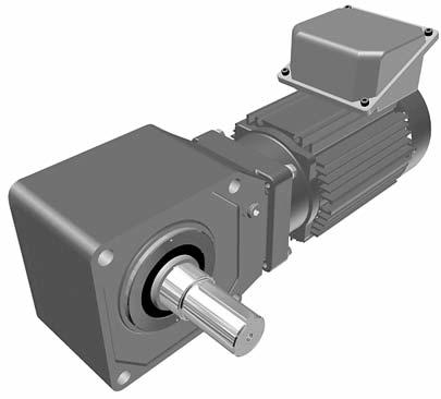
5 Hypoid Right Angle Gearmotors and Reducers Product Description The Sumitomo Gearmotor represents 60 years of excellence in the design and manufacture of premium gearing solutions. With millions of Hyponics currently in service, the product features a compact, modular housing, maintenance-free grease lubrication and high efficiency operation. Options include C- face quill design; unique FKM antimicrobial, multi-lipped rotary output seal; corrosion resistant, stainless output shaft and hardware; and synthetic NSF H-1, food-grade lubricant. NSF51 antimicrobial powder coating makes the ideal choice for food, beverage, and pharmaceutical industries. Sumitomo s patented, all-steel hypoidal gear technology leads the industry in quiet operation and high efficiency. The significantly outperforms worm gearing across ratios from 30:1 to 1440:1. Features & Benefits Patented Hyponic gear technology is up to 85% efficient across all ratios and requires no cooling fan NSF 51 approved antimicrobial powder coating protects against the growth of bacteria, mold, and fungus. All-steel hypoid gear design transmits torque more efficiently for more torque density in a compact unit Maintenance-free grease lubrication eliminates oil changes Compact, lightweight design in an aluminum, corrosion resistant housing with optional washdown protection Hollow bore makes installation and retrofit quick and easy Extremely quiet, smooth operation is ideal for commercial use Two-Year warranty Optional, popular keyed-hollow bore sizes available from stock: 1 3/16, 1 7/16, 1 15/16, 2 3/16 Specifications Ratios: 5:1 up to 1440:1 HP: 1/8 to 15 HP Maximum Torque: 13,100 in-lbs. Electrical: 230/460 VAC (Single and 3-Phase) Housing: Lightweight, corrosion-resistant aluminum Mounting: Flange, Bolt-On Feet Shafts: Hollow, Solid Input: Quill, C-Face Adapter or Integral Motor Optional plug-in shaft and bolton feet enhance mounting flexibility Modular Housing C-Face Quill Adapter, Plug-in Shaft, Foot Mount Applications Bottling & Food Processing Commercial Bakery Lines Pharmaceutical Machinery Automotive Assembly Plants Conveyor Lines & Material Handling Wood Processing & Paper Products Residential Elevators & Lifts Automated Bay & Dock Door Drives Crushers Dehydrators Packaging General Information 1.3
6 Product Range (Standard Motor and Reducer Combinations) Quill Reducer Options Frame Size Ratio (:1) Standard Bore* (inches) Output Torque at 1750 RPM Input (in lb) Available Motor Frames / C C C C 145TC 1-1/ C / C / C TC 1-3/ C 145TC / C / C C 145TC 1-1/ C / TC C-Face Reducer with Jaw Coupling Options Frame Size Ratio (:1) Standard Bore* (inches) Output Torque at 1750 RPM Input (in lb) Available Motor Frames / C 56C C 145TC C 56C / C 145TC / C 56C / C 56C / C 145TC / C / C 56C / C 145TC / C 145TC / C 184TC / C 145TC C 145TC *Optional bore sizes are available / C TC 184TC C 184TC TC C 145TC C *Optional bore sizes are available Gearmotor Reduction Ratios Combinations with 1750 RPM motor 1/3 3/ General Information
7 FAQs How do I select a reducer or gearmotor? Selection is based on the actual horsepower and/or torque requirements at the output shaft. The speed reducer has particularly high efficiencies over a wide range of reduction ratios, which frequently permits the use of reduced input power requirements (smaller HP motor) without sacrificing output shaft torque. The selection procedures in this catalog, Speed Reducers pages and Gearmotors pages , will guide you in choosing the most efficient reducer for your application. What information do I need to get started in the selection process? To select the proper reducer for your application, you will need to know: Application: type of driven machine Hours of operation per day Motor horsepower (HP) and speed (RPM) Loading Conditions Mounting Position If there are any special environmental factors or operation requirements, they must also be noted. This information will be important in determining the Service Factor of your application. What are service factors and how are they used? In general, reducers and gearmotors are rated for specific conditions and operating requirements of the application by the use of AGMA-defined Service Factors. There are three AGMA load classifications for reducers: uniform (U), moderate shock (M), and heavy shock (H) (page 2.6) and three AGMA load classifications for gearmotors: I, II, and III (page 3.8). The Service Factors are used in the product selection process to adjust for the specific conditions and operating requirements of your application. What do I do if my application has particularly severe operating conditions? The standard ratings for are based on 10-hour daily service under conditions of uniform loads (equivalent to AGMA service factor 1.0). By following the product selection process, you will determine and apply the Service Factors to compensate for severe operating conditions. How can I be sure that the reducer can withstand periodic excessive overloads? speed reducers provide 250% momentary intermittent shock load capacity. For applications with shock loads greater than 250%, consult a Sumitomo Application Engineer. What are the standard input speeds? In general terms, the speeds are 1750 and 1450 RPM. The selection tables in this catalog are based on 1750 RPM. The reducer selection tables show ratings at 1750 RPM for Quill models, and 1750 and 1450 for C-Face models. What are the thermal limitations of the? The speed reducer, by virtue of its smooth, almost frictionless operation (unlike traditional helical gears), has a thermal rating that far exceeds its mechanical capacity and all but eliminates the conventional limitations due to heat. What is the standard mounting of the? The is standardly supplied as a shaft mount with a keyed hollow bore. Options are available for a solid shaft with feet and a flange mounting configuration. Since the is grease lubricated as standard, it can be mounted in any position without modifications. Do you supply a torque arm? At what position should it be mounted? A torque arm assembly is offered as an option (Section 4). The standard torque arm assembly and standard mounting positions are shown in the Appendix on pages What is the required tolerance of the shaft to be used on the? Shaft tolerances will depend on the type of load and shock load of the application. Shaft tolerance recommendations are included in the Appendix on page 5.9 What is the rotation of the Hyponic shaft? The direction of shaft rotation on Hyponic reducers varies according to frame size and ratio. Please refer to page 5.3 in the Appendix for specific data on the shaft rotation of various models. General Information 1.5
8 FAQs continued What C-Face sizes are available for the? C-Face sizes are based on the size and ratio of the selection. The C-Face Reducer with Jaw Coupling Options table on page 1.4 lists available C-Face frame sizes. What should be considered when connecting to the shaft? When mounting a pulley, sprocket, or sheave, mount as close to the unit housing as possible; never mount beyond the midpoint of the shaft projection to avoid undue bearing load and shaft deflection. Never overtighten belts or chains. Careful and accurate installation is essential for best results and trouble-free operation. Before installing, the shafts should be checked to make sure they are parallel and level. After mounting, alignment should be checked with a string or straight edge held against the sides of the sprocket or pulley base. Couplings should be properly aligned to the limits specified by the manufacturer. Check alignment prior to initial startup on coupled units. When specifying stainless steel output shafts, consult a Sumitomo Applications Engineer for all applications where overhung load is present. Should overhung load and thrust load be considered when making a selection? Yes, loads imposed on the slow speed shaft will vary according to the method used to connect the shaft to the driven machine. Frequently, in addition to the torsional forces, radial (overhung) and thrust loads are applied to the slow speed shaft at the same time. For example, coupling connections normally involve torsional forces only. However, when power is transmitted through spur gears, belts, pulleys, or chains, both torsional and radial forces may be present. When driving through helical or bevel gears, all three conditions (torsional, radial, and thrust load) may be referred to the reducer shaft. The slow speed shaft and bearings must have sufficient strength to withstand these loads, and it is necessary to determine the allowable limits for each condition. Page 5.5 in the Appendix explains how to calculate the overhung load (radial) applied to the output shaft. What is meant by load centering? The reducer s radial load capacities are calculated at the midpoint of the slow speed shaft extension. Radial load capacities decrease if the center of the load is moved farther from the reducer and the values obtained must be adjusted accordingly. Refer to page 5.5 in the Appendix for load location factors. What modification features do you offer for the food and beverage industry? We offer DuPont Alesta Silver Freeze antimicrobial powder coating, harsh duty FKM antimicrobial seals, NSF H1 synthetic lubricant, stainless steel shaft and hardware. Modifications can be added individually or as packages, please see page 4.14 in the Options section for package details. 1.6 General Information
9 Standard Specifications Standard Specifications Standard Specifications with Built-In Brake 3-Phase Capacity Range: 1/8 HP ~ 15 HP, 4P 1/8 HP ~ 15 HP, 4P: FB Brake Integral Motor Enclosure: Totally enclosed fan cooled type Totally enclosed fan cooled type (1/8 HP, 4P Totally enclosed non ventilated) (1/8 HP, 4P Totally enclosed non ventilated) Power Supply: 230/460 Volts, 60 Hz 230/460 Volts, 60 Hz 575 Volts, 60 Hz 575 Volts, 60 Hz Insulation: 1/8 ~ 1/2 HP: Class F 1/8 ~ 1/2 HP: Class F, Brake: Class F 3/4 ~ 15 HP: Class F 3/4 ~ 15 HP: Class F, Brake: Class F Time Rating Continuous Continuous Inverter Duty Capacity Range: 1/8 HP ~ 10 HP, 4P 1/8 HP ~ 10 HP, 4P: FB Brake Integral Motor Enclosure: Totally enclosed fan cooled type Totally enclosed fan cooled type Power Supply: 230/460 Volts, 60 Hz 230/460 Volts, 60 Hz Insulation: Class F Class F, Brake: Class F Time Rating Continuous (6-60Hz constant torque) Continuous (6-60Hz constant torque) Reducer Reduction: Combination of hypoid gear input and involute gear output. Lubrication: Grease lubricated; filled with special high-grade grease prior to shipment. Seals: Nitrile material, triple lipped output seals. Material: Casing: aluminum alloy; Gear: chrome-molybdenum steel Paint Color: Blue, Muenters color number 6.5PB 3.6/8.2 or DuPont Alesta Silver Freeze AM powder coat Bearings: Ball bearings on input and output. Ambient Installation Location: Indoors (Minimal dust and humidity) Conditions Ambient Temperature: 14 ~104 F (-10º ~ 40º C) Ambient Humidity: Under 85% Elevation: Under 3,281 ft. (1000 meters) Atmosphere: Well ventilated location, free of corrosive gases, explosive gases, vapors and dust. Shaft Rotation The direction of shaft rotation on Hyponic reducers varies according to frame size and ratio. Please refer to page 5.3 in the Appendix for specific data on the shaft rotation of various models. Input Speeds In general terms, the speeds are 1750 and 1165 RPM. The selection tables in this catalog are based on 1750 RPM. The reducer selection tables show ratings at 1750 and 1450 RPM. Thermal Capacity The speed reducer, by virtue of its smooth, almost frictionless operation (unlike traditional helical gears), has a thermal rating that far exceeds its mechanical capacity and all but eliminates the conventional limitations due to heat. General Information 1.7
10 This page intentionally left blank. 1.8 General Information
11 Speed Reducers 2 Speed Reducers Hollow Shaft Type Speed Reducers How to Select Speed Reducers 2.1
12 Speed Reducers How to select a Speed Reducer Step 1: Step 2: Collect data about your application Before starting you need to know the: Application (e.g. Conveyor, Mixer, etc.) Hours of Operation per day Motor Horsepower (HP) and Speed (RPM) Desired Output Speed Mounting Position and Style Overhung or Thrust Loads Bore Dimensions, inch or metric Select a Frame Size 2A: Find the Load Classification of your application in the AGMA Load Classification Table on page 2.6. Speed Reducers How to Select 2B: Find the recommended Service Factor using the Recommended Reducer Service Factor Table or Recommended Service Factors for Frequent Start-Stop Applications Table on the right. 2C: Determine the Selection Horsepower by multiplying the Motor Horsepower by the Service Factor. 2D: Select a Frame size from the Reducer Selection Tables on pages by matching both the Selection Horsepower and Desired Output Speed (RPMs) to a frame size model number. Step 3: Step 4: Step 5: Verify Dimensions Use the Dimensions information on pages to verify that the selected Frame Size is appropriate. Choose Options The following options may apply: Solid Shaft Mounting Feet Output Flange Torque Arm Assembly Washdown Modification Please see the pricelist for available modifications, and refer to Section 4 of this catalog for dimension drawings of selected popular options. Configure a Model Number Go to page 2.4 to configure a model number. Note: You will use the information you gather from the procedure on this page to Configure a Model Number. 2.2 Speed Reducers
![Speed Reducers Recommended Reducer Service Factors AGMA Load Classifications Uniform (U) Moderate Shock (M) Heavy Shock (H) 1/2 hr. per day (Occasional) 0.50 [1] 0.80 [1] 1.](/docs-images/75/71598645/images/13-0.jpg "25 Duration of Service 3 hrs. per day (Intermittent) 0.80 1.00 1.50 Up to 10 hrs. per day 1.00 1.25 1.75 24 hrs. per day 1.20 1.50 2.")
13 Speed Reducers Recommended Reducer Service Factors AGMA Load Classifications Uniform (U) Moderate Shock (M) Heavy Shock (H) 1/2 hr. per day (Occasional) 0.50 [1] 0.80 [1] 1.25 Duration of Service 3 hrs. per day (Intermittent) Up to 10 hrs. per day hrs. per day Note: [1] Maximum momentary or starting load must not exceed 300% of gear reducer rating (rating meaning service factor of 1.0). Time specified for occasional and intermittent service refers to total operating time per day. Recommended Service Factors for Frequent Start Stop Applications For frequent start-stop applications, use the table below to determine the recommended service factor, and check the Motor Thermal Rating (Table 5.33) in Section 5. Number of starts ~10 hours/day ~24 hours/day (Times/hour) I II III I II III ~ ~ ~ Speed Reducers The Moment of Inertia (ratio of Inertia WR 2 ) = Total Moment of Inertia (WR2 ) as seen from motor shaft Moment of Inertia (WR 2 ) of motor I = Allowable ratio of Moment of Inertia (WR2) < 0.3 II = Allowable ratio of Moment of Inertia (WR2) < 3 III = Allowable ratio of Moment of Inertia (WR2) < 10 How to Select Determine Selection Horsepower (HP) Motor HP X Service Factor = Selection HP Example: 10 Motor HP X 1.25 Service Factor = 12.5 Selection HP Select a Frame Size 1 Match your OUTPUT RPM (or RATIO)... Output RPM Frame Ratio Size Input HP Output Torque in lbs Overhung Load lbs Input HP Output Torque in lbs Overhung Load lbs Input HP Output Torque in lbs Overhung Load lbs...to your Input HP Output Torque in lbs SELECTION HP Overhung Load lbs Input HP Output Torque in lbs Overhung Load lbs to find your FRAME SIZE If Overhung Load is present, it must be checked against the capacity of the selection. For special circumstances affecting Frame Size selection such as: Overhung Load Shock Loading Consult Appendix, pages Speed Reducers 2.3
14 Speed Reducers Configure a Model Number Output Shaft Orientation Type Universal Direction (Maintenance Free) Mounting Style Prefix N Include the following information when ordering: Motor Specification (230/460 VAC 60 Hz is supplied, unless otherwise specified) NEMA frame size for C-face adapter with jaw coupling or Quill adapter Bushing Bore size (must be supplied) Optional conduit box positions must be specified, otherwise Y1 is supplied. Type Shaft Mount (Hollow Shaft) Flange (Solid Shaft) Foot (Solid Shaft) Prefix Y F H Input Connection Frame Size Output Shaft Direction (shafted model only) Speed Reducers Nomenclature Input Connection C-Face Adapter with jaw coupling Quill C-Face Motor Modification Prefix Prefix J X JM Direction (when viewed from motor end) Projects to Left Side Projects to Right Side Projects to Both Sides Suffix L R T Special S Standard R N Y X Y - J1-20 Frame size Ratio Input connection Mounting style Output shaft orientation Hyponic product code (always R ) Modification (Special feature) Shaft specification Optional specification (as required) Output shaft direction (shafted model only) 2.4 Speed Reducers
15 Speed Reducers Nomenclature Shaft Specifications Input Shaft Output Shaft Hollow Solid Suffix mm Key (mm) Key (mm) Inch Key (Inch) Key (Inch) Y Optional Specifications (as required) F1 G1 Specification Suffix Hollow Bore Options Extended Flange (for motor clearance) Left (viewed from motor end) F1 Speed Reducers Right (viewed from motor end) Solid Shaft Options Plug-in Shaft Plug-in Shaft with Bolt-on Feet G1 X1 X1 Nomenclature Bottom J1 Opposite from Motor S1 Top M1 Plug-in Shaft with Extended Flange (for motor clearance) J1 S1 M1 Left (viewed from motor end) P1 Right (viewed from motor end) Q1 P1 Q1 Nominal Total Ratio Nomenclature Example: RNYX 1220Y J1 20 R N Universal Mount Y Shaft Mount (Hollow Shaft) X Quill C-Face Input 1220 Frame Size Y Inch Shaft Specification J1 Bolt-on Feet, Bottom 20 Ratio Speed Reducers 2.5
16 Speed Reducers 2.6 Speed Reducers AGMA Tables Speed Reducers AGMA Load Classifications Agitators Pure liquids U Liquids and solids M Variable-density liquids M Blowers Centrifugal U Lobe M Vane U Brewing and Distilling Bottling machinery U Brew kettles, cont. duty U Cookers, cont. duty U Mash tubs, cont. duty U Scale hopper, frequent starts M Can Filling Machines U Cane Knives M Car Dumpers H Car Pullers M Clarifiers U Classifiers M Clay Working Machinery Brick press H Briquette machine H Clay working machinery M Pug mill M Compressors Centrifugal U Lobe M Reciprocating, multi-cylinder M Reciprocating, single-cylinder H Conveyors Uniformly Loaded or Fed Apron U Assembly U Belt U Bucket U Chain U Flight U Oven U Screw U Conveyors Heavy Duty, Not Uniformly Fed Apron M Assembly M Belt M Bucket M Chain M Flight M Live roll oven M Reciprocating H Screw M Shaker H Cranes (Except for Dry Dock Cranes) Main hoists U Bridge travel S Trolley travel S Crusher Ore H Stone H Sugar M Dredges Cable reels M Conveyors M Cutter head drives H Jig drives H Maneuvering winches M Pumps M Screen drive H Stackers M Utility winches M Dry Dock Cranes S Elevators Bucket, uniform load U Bucket, heavy load M Bucket, cont U Centrifugal discharge U Escalators U Freight M Gravity discharge U Man lifts S Passenger S Extruders (Plastics) Blow molders M Coating U Film U Pipe U Pre-plasticizers M Rods U Sheet U Tubing U Fans Centrifugal U Cooling towers S Forced draft S Induced draft M Large (mine, etc.) M Large (industrial) M Light (small diameter) U Feeders Apron M Belt M Disc U Reciprocating H Screw M Food Industry Beet slicer M Cereal cooker U Dough mixer M Meat grinders M Generators (Not Welding) U Hammer Mills H Hoists Heavy duty H Medium duty M Skip M Laundry Washers Reversing M Laundry Tumblers M Line Shaft Drive processing equipment M Light U Other line shafts U Lumber Industry Barkers hydraulic and mechanical S Burner conveyor M Chain Saw and Drag Saw H Chain transfer H Craneway transfer H De-barking drum S Edger feed H Gang feed M Geen chain M Live rolls H Log haul-lockline H Log turning device H Main log conveyor H Off bearing rolls M Planer feed chains M Planer floor chains M Planer tilting hoist M Re-saw merry-go-round conveyor M Roll cases H Slab conveyor H Small waste-conveyor-belt U Small waste-conveyor-chain M Sorting table M Tipple hoist conveyor M Tipple hoist drive M Transfer conveyors M Transfer rolls M Tray drive M Trimmer feed M Waste conveyor M Machine Tools Bending roll M Notching press, belt driven S Plate planer H Punch press, gear driven H Tapping machine H Other machine tools Main drives M Auxiliary drives U Metal Mills Draw bench carriage and main drive M Forming machines H Pinch, dryer and scrubber rolls, reversing.... S Slitters M Table conveyors, nonreversing Group drives M Individual drives H Table conveyors, reversing S Wire drawing and flattening machine M Wire winding machine M Mills, Rotary Type Ball M Cement kilns M Dryers and coolers M Kilns M Pebble M Rod, plain and wedge bar M Tumbling barrels H Mixers Concrete mixers, cont M Concrete mixers, intermittent M Constant density U Variable density M Oil Industry Chillers M Oil well pumps S Paraffin filter press M Rotary kilns M Paper Mills Agitators (mixers) M Barker, hydraulic S Barker, mechanical S Barking drum S Beater and pulper M Bleacher U Calenders M Calenders, super H Converting machine (except cutters, platers). M Conveyors U Couch M Cutters, platers H Cylinders M Dryers M Felt stretcher M Felt whipper H Jordans H Log haul H Presses U Pulp machine reel M Stock chest M Suction roll U Washers and thickeners M Winders U Printing Presses S Pullers, Barge Haul H Pumps Centrifugal U Proportioning M Reciprocating Single acting, 3 or more cylinders M Double acting, 2 or more cylinders M Rotary-gear type U Rubber and Plastics Industries Crackers H Laboratory equipment M Mixing mills H Refiners M Rubber calenders M Rubber mill (2 on line) M Rubber mill (3 on line) U Sheeter M Tire building machines S Tire and tube press openers S Tubers and strainers M Warming mills M Sand Muller M Screens Air washing U Rotary, stone or gravel M Traveling water intake U Sewage Disposal Equipment Bar screens U Chemical fenders U Collectors, circuline or straightline U Dewatering screens M Grit collectors U Scum breakers M Slow or rapid mixers M Sludge collectors U Thickeners M Vacuum filters M Slab Pushers M Steering Gear S Stokers U Sugar Industry Cane knives M Crushers M Mills H Textile Industry Batchers M Calenders M Cards M Dry cans M Dryers M Dyeing machinery M Knitting machines S Looms M Mangles M Nappers M Pads M Range drives S Slashers M Soapers M Spinners M Tenter frames M Washers M Winders M Windlass S TYPE OF TYPE OF APPLICATION LOAD TYPE OF TYPE OF APPLICATION LOAD TYPE OF TYPE OF APPLICATION LOAD U = Uniform Load H = Heavy Shock M = Moderate Shock S = Contact Sumitomo
17 This page intentionally left blank. Speed Reducers 2.7
18 Speed Reducers Quill Frame Size Selection Tables 60 Hz Dimensions: Frame Size Page Frame Size Page 1750 RPM Speed Reducers Selection Tables Output RPM Frame Ratio Size Input HP Output Torque in lbs Overhung Load lbs Input HP Output Torque in lbs Overhung Load lbs Input HP Output Torque in lbs Overhung Load lbs Input HP Output Torque in lbs Overhung Load lbs Input HP Output Torque in lbs Overhung Load lbs Input HP Output Torque in lbs 1340 Overhung Load lbs Input HP Output Torque in lbs Overhung Load lbs Input HP Output Torque in lbs Overhung Load lbs Input HP Output Torque in lbs 1440 Overhung Load lbs Input HP Output Torque in lbs Overhung Load lbs Input HP Output Torque in lbs Overhung Load lbs Input HP Output Torque in lbs 1540 Overhung Load lbs Input HP Output Torque in lbs Overhung Load lbs Input HP Output Torque in lbs 1631 Overhung Load lbs Input HP Output Torque in lbs Overhung Load lbs Input HP Output Torque in lbs 1640 Overhung Load lbs 2.8 Speed Reducers RPM Selection Tables
19 Speed Reducers 60 Hz Quill Frame Size Selection Tables Dimensions: Frame Size Page Frame Size Page RPM Output RPM Frame Ratio Size Input HP Output Torque in lbs 1120 Overhung Load lbs Input HP Output Torque in lbs 1220 Overhung Load lbs Input HP Output Torque in lbs Overhung Load lbs Input HP Output Torque in lbs 1320 Overhung Load lbs Input HP Output Torque in lbs Overhung Load lbs Input HP Output Torque in lbs Overhung Load lbs Input HP Output Torque in lbs 1420 Overhung Load lbs Input HP Output Torque in lbs Overhung Load lbs Input HP Output Torque in lbs Overhung Load lbs Input HP Output Torque in lbs Overhung Load lbs Input HP Output Torque in lbs 1531 Overhung Load lbs Input HP Output Torque in lbs Overhung Load lbs Input HP 3.00 Output Torque in lbs Overhung Load lbs 2200 Input HP Output Torque in lbs Overhung Load lbs Input HP Output Torque in lbs 1632 Overhung Load lbs Input HP Output Torque in lbs Overhung Load lbs Speed Reducers Selection Tables Speed Reducers RPM Selection Tables 2.9
20 Speed Reducers C-Face Frame Size Selection Tables 60 Hz Dimensions: Frame Size Page Frame Size Page 1750 RPM Speed Reducers Selection Tables Output RPM Frame Ratio Size Input HP Output Torque in lbs Overhung Load lbs Input HP Output Torque in lbs Overhung Load lbs Input HP Output Torque in lbs Overhung Load lbs Input HP Output Torque in lbs Overhung Load lbs Input HP Output Torque in lbs Overhung Load lbs Input HP Output Torque in lbs 1340 Overhung Load lbs Input HP Output Torque in lbs Overhung Load lbs Input HP Output Torque in lbs Overhung Load lbs Input HP Output Torque in lbs 1440 Overhung Load lbs Input HP Output Torque in lbs Overhung Load lbs Input HP Output Torque in lbs Overhung Load lbs Input HP Output Torque in lbs Overhung Load lbs Input HP Output Torque in lbs 1540 Overhung Load lbs Input HP Output Torque in lbs 1640 Overhung Load lbs 2.10 Speed Reducers RPM Selection Tables
21 Speed Reducers 60 Hz C-Face Frame Size Selection Tables Dimensions: Frame Size Page Frame Size Page RPM Output RPM Frame Ratio Size Input HP Output Torque in lbs 1120 Overhung Load lbs Input HP Output Torque in lbs 1220 Overhung Load lbs Input HP Output Torque in lbs Overhung Load lbs Input HP Output Torque in lbs 1320 Overhung Load lbs Input HP Output Torque in lbs Overhung Load lbs Input HP Output Torque in lbs Overhung Load lbs Input HP Output Torque in lbs 1420 Overhung Load lbs Input HP Output Torque in lbs Overhung Load lbs Input HP Output Torque in lbs Overhung Load lbs Input HP Output Torque in lbs 1520 Overhung Load lbs Input HP Output Torque in lbs Overhung Load lbs Input HP Output Torque in lbs 1531 Overhung Load lbs Input HP Output Torque in lbs Overhung Load lbs Input HP Output Torque in lbs Overhung Load lbs Speed Reducers Selection Tables Speed Reducers RPM Selection Tables 2.11
22 Speed Reducers C-Face Frame Size Selection Tables 50 Hz 1450 RPM Dimensions: Frame Size Page Frame Size Page Speed Reducers Selection Tables Output RPM Frame Ratio Size Input HP Output Torque in lbs Overhung Load lbs Input HP Output Torque in lbs Overhung Load lbs Input HP Output Torque in lbs Overhung Load lbs Input HP Output Torque in lbs Overhung Load lbs Input HP Output Torque in lbs Overhung Load lbs Input HP Output Torque in lbs 1340 Overhung Load lbs Input HP Output Torque in lbs Overhung Load lbs Input HP Output Torque in lbs Overhung Load lbs Input HP Output Torque in lbs 1440 Overhung Load lbs Input HP Output Torque in lbs Overhung Load lbs Input HP Output Torque in lbs Overhung Load lbs Input HP Output Torque in lbs Overhung Load lbs Input HP Output Torque in lbs 1540 Overhung Load lbs Input HP Output Torque in lbs 1640 Overhung Load lbs 2.12 Speed Reducers RPM Selection Tables
23 Speed Reducers 50 Hz C-Face Frame Size Selection Tables Dimensions: Frame Size Page Frame Size Page RPM Output RPM Frame Ratio Size Input HP Output Torque in lbs 1120 Overhung Load lbs Input HP Output Torque in lbs 1220 Overhung Load lbs Input HP Output Torque in lbs Overhung Load lbs Input HP Output Torque in lbs 1320 Overhung Load lbs Input HP Output Torque in lbs Overhung Load lbs Input HP Output Torque in lbs Overhung Load lbs Input HP Output Torque in lbs 1420 Overhung Load lbs Input HP Output Torque in lbs Overhung Load lbs Input HP Output Torque in lbs Overhung Load lbs Input HP Output Torque in lbs 1520 Overhung Load lbs Input HP Output Torque in lbs Overhung Load lbs Input HP Output Torque in lbs 1531 Overhung Load lbs Input HP Output Torque in lbs Overhung Load lbs Input HP Output Torque in lbs Overhung Load lbs Speed Reducers Selection Tables Speed Reducers RPM Selection Tables 2.13
24 Speed Reducers Quill Dimensions Frame Size 1100 RNYX-1120Y CE P D D P L A N C XV Z C AJ B DIA B DIA A1 J L K ZA E R AK BD F G F 4X H DIA K A2 A E X BB C-C (ADAPTER ONLY) C 4X BF DIA HOLE Speed Reducers Dimensions All dimensions are in inches. Ø Ø A-A Ø INPUT SHAFT KEYWAY Model A1 A2 B min B max D E F G H J K L N P R X 1120Y XU Model Ratio NEMA Frame CE C AK BD AJ BF Z BB ZA RNYX-1120Y 5~60 56C Wt. (lbs.) Model NEMA Frame XU XV KEYWAY RNYX-1120Y 56C /16 x 3/16 x Speed Reducers Dimensions Dimensions shown are for reference only and are subject to change without notice, unless certified. Certified prints are available after receipt of an order; consult factory.
25 Speed Reducers Quill Dimensions P D D P L CE C N A XV Z C Frame Size 1200 RNYX-1220/30Y AJ B DIA B DIA L K ZA R A1 J E BD AK F G F 4X H DIA K A2 A E X BB C-C (ADAPTER ONLY) C 4X BF DIA HOLE Ø KEYWAY All dimensions are in inches. Ø A-A 1.50 Ø INPUT SHAFT XU Speed Reducers Dimensions Model A1 A2 B min B max D E F G H J K L N P R X 1220Y Y Model Ratio NEMA Frame CE C AK BD AJ BF Z BB ZA RNYX-1220Y 5~60 56C RNYX-1230Y 80~120 56C Wt. (lbs.) Model NEMA Frame XU XV KEYWAY RNYX-1220Y 56C /16 x 3/16 x 1.82 RNYX-1230Y 56C /16 x 3/16 x 1.82 Dimensions shown are for reference only and are subject to change without notice, unless certified. Certified prints are available after receipt of an order; consult factory. Speed Reducers 2.15 Dimensions
26 Speed Reducers Quill Dimensions Frame Size 1300 RNYX-1320/30/40Y P D D P L A C N CE Z XV C AJ B DIA B DIA A1 L J K E R AK BD ZA F Q G I DIA 4X H DIA F K A E A2 X BB C-C (ADAPTER ONLY) C 4X BF DIA HOLE Speed Reducers Dimensions All dimensions are in inches. Ø Ø A-A Ø INPUT SHAFT KEYWAY Model A1 A2 B min B max D E F G H J K L N P R X 1320Y Y Y XU Model Ratio NEMA Frame CE C AK BD AJ BF Z BB ZA RNYX-1320Y 5~60 56C RNYX-1320Y 5~30 143TC RNYX-1330Y 80~240 56C RNYX-1340Y 300~720 56C Wt. (lbs.) Model NEMA Frame XU XV KEYWAY RNYX-1320Y 56C /16 x 3/16 x 1.92 RNYX-1320Y 143TC /16 x 3/16 x 1.92 RNYX-1330Y 56C /16 x 3/16 x 1.85 RNYX-1340Y 56C /16 x 3/16 x Speed Reducers Dimensions Dimensions shown are for reference only and are subject to change without notice, unless certified. Certified prints are available after receipt of an order; consult factory.
27 Speed Reducers Quill Dimensions P D D P L A C N CE Z XV C Frame Size 1400 RNYX-1420/30/40Y AJ B DIA B DIA A1 L J K E R AK BD ZA F Q G I DIA F 4X H DIA K A E A2 X BB C-C (ADAPTER ONLY) C 4X BF DIA HOLE Ø KEYWAY All dimensions are in inches. Ø A-A 2.05 Ø INPUT SHAFT Model A1 A2 B min B max D E F G H J K L N P R X 1420Y Y Y XU Speed Reducers Dimensions Model Ratio NEMA Frame CE C AK BD AJ BF Z BB ZA RNYX-1420Y 5~60 56C~145TC RNYX-1430Y 80~240 56C RNYX-1440Y 300~ C Wt. (lbs.) Model NEMA Frame XU XV KEYWAY RNYX-1420Y 56C /16 x 3/16 x 1.82 RNYX-1420Y 143TC /16 x 3/16 x 1.92 RNYX-1430Y 56C /16 x 3/16 x 1.92 RNYX-1440Y 56C /16 x 3/16 x 1.85 Dimensions shown are for reference only and are subject to change without notice, unless certified. Certified prints are available after receipt of an order; consult factory. Speed Reducers 2.17 Dimensions
28 Speed Reducers Quill Dimensions Frame Size 1500 RNYX-1530/31/40Y CE P D D P L A C N Z XV C AJ B DIA B DIA L K A1 J E R AK BD ZA F Q G I DIA F 4X H DIA K A E A2 X BB C-C (ADAPTER ONLY) C 4X BF DIA HOLE Speed Reducers Dimensions All dimensions are in inches. Ø Ø A-A Ø INPUT SHAFT KEYWAY XU Model A1 A2 B min B max D E F G H J K L N P R X 1530/31Y Y Model Ratio NEMA Frame CE C AK BD AJ BF Z BB ZA RNYX-1530Y 80~240 56C RNYX-1530Y 80~ TC~145TC RNYX-1531Y 40 ~ TC~145TC RNYX-1540Y 300~ C Wt. (lbs.) Model NEMA Frame XU XV KEYWAY RNYX-1530Y 56C /16 x 3/16 x 1.92 RNYX-1530Y 143TC /16 x 3/16 x 1.92 RNYX-1531Y 145TC /16 x 3/16 x 1.92 RNYX-1540Y 56C /16 x 3/16 x Speed Reducers Dimensions Dimensions shown are for reference only and are subject to change without notice, unless certified. Certified prints are available after receipt of an order; consult factory.
29 Speed Reducers Quill Dimensions Frame Size 1600 RNYX-1630/31/32/40Y P D D P L CE C N A 1 ZA XV C AJ B DIA F G L K B DIA A1 E J 4X H DIA F K L A2 A E J 2 ZA R MIN I.D. AK BB Z BD C-C (ADAPTER ONLY) 4X DIA BF HOLE C Ø KEYWAY All dimensions are in inches. Ø A-A 2.99 Ø INPUT SHAFT Model A1 A2 B min B max D E F G H J K L N P R ZA /31/32Y Y XU Speed Reducers Dimensions Model Ratio NEMA Frame CE C AK BD AJ BF Z BB ZA 2 Wt. (lbs.) RNYX-1630Y 10 ~ TC~145TC RNYX-1630Y 10 ~ TC~184TC RNYX-1631Y 150~240 56C RNYX-1631Y 150~ TC~145TC RNYX-1631Y 150~ TC~184TC RNYX-1632Y 10~60 182TC~184TC RNYX-1640Y 300~ C RNYX-1640Y 300~ TC~145TC Model NEMA Frame XU XV KEYWAY RNYX-1630Y 143TC /16 x 3/16 x 2.36 RNYX-1630Y 182TC /4 x 1/4 x 2.16 RNYX-1631Y 56C /16 x 3/16 x 1.86 RNYX-1631Y 143TC /16 x 3/16 x 2.36 RNYX-1631Y 182TC /4 x 1/4 x 2.16 RNYX-1632Y 182TC /4 x 1/4 x 2.16 RNYX-1640Y 56C /16 x 3/16 x 1.82 RNYX-1640Y 143TC /16 x 3/16 x 1.92 Dimensions shown are for reference only and are subject to change without notice, unless certified. Certified prints are available after receipt of an order; consult factory. Speed Reducers 2.19 Dimensions
30 Speed Reducers C-Face Dimensions Frame Size 1100 RNYJ-1120Y C CE XJ P D D P L A N B XV Z BB C AJ B DIA B DIA L A1 J K E R MIN I.D. AK BD ZA F G F 4X H DIA K A2 A E X B C-C (ADAPTER ONLY) C 4X BF DIA HOLE Ø KEY Speed Reducers Dimensions All dimensions are in inches. Ø A-A 1.22 Ø XU B-B Model A1 A2 B min B max D E F G H J K L N P R X 1120Y Model Ratio NEMA Frame CE C XJ AK BD AJ BF Z BB Min. ID ZA Wt. (lbs.) RNYJ-1120Y 5~60 42C RNYJ-1120Y 5~60 48C RNYJ-1120Y 5~30 56C Model XU XV KEYWAY RNYJ-1120Y /8 x 1/8 x Speed Reducers Dimensions Dimensions shown are for reference only and are subject to change without notice, unless certified. Certified prints are available after receipt of an order; consult factory.
31 Speed Reducers C-Face Dimensions P D D P L A N C CE B XV XJ Z BB C Frame Size 1200 RNYJ-1220/30Y AJ B DIA B DIA A1 J L K E R MIN I.D. AK BD ZA F G F 4X H DIA K A2 A E X B C-C (ADAPTER ONLY) C 4X BF DIA HOLE All dimensions are in inches. Ø Ø A-A 1.50 Ø Model A1 A2 B min B max D E F G H J K L N P R X Y Y XU B-B KEY Speed Reducers Dimensions Model Ratio NEMA Frame CE C XJ AK BD AJ BF Z BB RNYJ-1220Y 5~60 48C RNYJ-1220Y 5~60 56C RNYJ-1220Y 5~60 143TC RNYJ-1230Y 80~240 42C RNYJ-1230Y 80~240 48C RNYJ-1230Y 80~240 56C Min. ID ZA Wt. (lbs.) Model XU XV KEYWAY RNYJ-1220Y /8 x 1/8 x 0.71 RNYJ-1230Y /8 x 1/8 x 0.71 Dimensions shown are for reference only and are subject to change without notice, unless certified. Certified prints are available after receipt of an order; consult factory. Speed Reducers 2.21 Dimensions
32 Speed Reducers C-Face Dimensions Frame Size 1300 RNYJ-1320/30/40Y Speed Reducers Dimensions All dimensions are in inches. F P B DIA D Q G D P B DIA I DIA F A1 L K J 4X H DIA Ø E L K Ø A-A A A E A C N R.25 CE X B B Ø XV XJ MIN I.D. C-C (ADAPTER ONLY) AK XU B-B Z BB ZA BD KEY C C AJ 4X BF DIA HOLE Model A1 A2 B min B max D E F G H J K L N P R X 1320Y Y Y Model Ratio NEMA Frame CE C XJ AK BD AJ BF Z BB RNYJ-1320Y 5~60 56C RNYJ-1320Y 5~30 143TC RNYJ-1330Y 80~240 48C RNYJ-1330Y 80~240 56C RNYJ-1340Y 300~ C RNYJ-1340Y 300~720 48C RNYJ-1340Y 300~720 56C Min. ID ZA Wt. (lbs.) Model XU XV KEYWAY RNYJ-1320Y /16 x 3/16 x 0.75 RNYJ-1330Y /8 x 1/8 x 0.71 RNYJ-1340Y /8 x 1/8 x Speed Reducers Dimensions Dimensions shown are for reference only and are subject to change without notice, unless certified. Certified prints are available after receipt of an order; consult factory.
33 Speed Reducers C-Face Dimensions P D D P L A C N CE B XV XJ Z BB Frame Size 1400 RNYJ-1420/30/40Y C AJ B DIA B DIA A1 L J K E R MIN I.D. AK BD ZA F Q G I DIA F 4X H DIA K A E A2 X B C-C (ADAPTER ONLY) C 4X BF DIA HOLE Ø KEY All dimensions are in inches. Ø A-A 2.05 Ø Model A1 A2 B min B max D E F G H J K L N P R X 1420Y Y Y XU B-B Speed Reducers Dimensions Model Ratio NEMA Frame CE C XJ AK BD AJ BF Z BB RNYJ-1420Y 40~60 42C RNYJ-1420Y 40~60 48C RNYJ-1420Y 40~60 56C RNYJ-1420Y 40~60 143TC RNYJ-1420Y 5~30 143TC~145TC RNYJ-1430Y 80~120 56C RNYJ-1430Y 150~240 56C RNYJ-1440Y 300~ C RNYJ-1440Y 300~720 56C Min. ID ZA Wt. (lbs.) Model XU XV KEYWAY RNYJ-1420Y /16 x 3/16 x 0.75 RNYJ-1430Y /16 x 3/16 x 0.75 RNYJ-1440Y /8 x 1/8 x 0.71 Dimensions shown are for reference only and are subject to change without notice, unless certified. Certified prints are available after receipt of an order; consult factory. Speed Reducers 2.23 Dimensions
34 Speed Reducers C-Face Dimensions Frame Size 1500 RNYJ-1520/30/31/40Y P D D P L A C N CE B XV XJ Z BB C AJ B DIA B DIA L K A1 J E R MIN I.D. AK ZA BD F Q G I DIA F 4X H DIA K A E A2 X B C-C (ADAPTER ONLY) C 4X BF DIA HOLE Ø KEY Speed Reducers Dimensions All dimensions are in inches. Ø A-A 2.28 Ø XU B-B Model A1 A2 B min B max D E F G H J K L N P R X 1520Y /31Y Y Model Ratio NEMA Frame CE C XJ AK BD AJ BF Z BB RNYJ-1520Y 5~60 56C~145TC RNYJ-1530Y 80~120 42C RNYJ-1530Y 80~120 48C RNYJ-1530Y 80~120 56C RNYJ-1530Y 80~120 42C~56C RNYJ-1530Y 150~240 56C RNYJ-1530Y 150~240 42C RNYJ-1531Y 40~80 56C~145C RNYJ-1540Y 300~ C~145TC Min. ID ZA Wt. (lbs.) Model XU XV KEYWAY RNYJ-1520Y /16 x 3/16 x 1.02 RNYJ-1530/31Y /16 x 3/16 x 0.75 RNYJ-1540Y /16 x 3/16 x Speed Reducers Dimensions Dimensions shown are for reference only and are subject to change without notice, unless certified. Certified prints are available after receipt of an order; consult factory.
35 Speed Reducers C-Face Dimensions P D D P L CE C N A 1 ZA B XV XJ C AJ Frame Size 1600 RNYJ-1640Y B DIA F G L K B DIA A1 E J 4X H DIA F K L A2 A E J R ZA 2 B MIN I.D. BD AK Z C-C (ADAPTER ONLY) 4X DIA BF HOLE C Ø KEY All dimensions are in inches. Ø A-A 2.99 Ø XU B-B Speed Reducers Dimensions Model A1 A2 B min B max D E F G H J K L N P R ZA Y Model Ratio NEMA Frame CE C XJ AK BD AJ BF Z RNYJ-1640Y 300~720 56C ~ 145TC RNYJ-1640Y 900~ C ~ 145TC Min. ID ZA 2 Wt. (lbs.) Model XU XV KEYWAY RNYJ-1640Y /16 x 3/16 x 0.75 Dimensions shown are for reference only and are subject to change without notice, unless certified. Certified prints are available after receipt of an order; consult factory. Speed Reducers 2.25 Dimensions
36 Speed Reducers This page intentionally left blank Speed Reducers
37 Gearmotors 3 Gearmotors Hollow Shaft Type Gearmotors How to Select Gearmotors 3.1
38 Gearmotors Product Range Hollow Shaft Type Selections shaded in blue offer an increased service factor. Please refer to the gearmotor selection tables for specific unit service factor details. Nominal Ratio (:1) Output RPM (1750 rpm input) /8HP Size 1120, Bore Ø0.75" Size 1220, Bore Ø1.00" 1/4HP Size 1120, Bore Ø0.75" Size 1220, Bore Ø1.00" Size 1220, Bore Ø1.00" Size 1320, Bore Ø1.25" 1/3HP Size 1220, Bore Ø1.00" Size 1320, Bore Ø1.25" 1/2HP Size 1220, Bore Ø1.00" Size 1320, Bore Ø1.25" Size 1320, Bore Ø1.25" Size 1420, Bore Ø1.375" 3/4HP Size 1320, Bore Ø1.25" Size 1420, Bore Ø1.375" 3-Phase 1HP Size 1320, Bore Ø1.25" Size 1420, Bore Ø1.375" Size 1420, Bore Ø1.375" Size 1520, Bore Ø1.50" 1.5HP Size 1420, Bore Ø1.375" Size 1520, Bore Ø1.50" Gearmotors 2HP Size 1420, Bore Ø1.375" Size 1520, Bore Ø1.50" Size 1520, Bore Ø1.50" Size 1531, Bore Ø1.50" Product Range 3HP 5HP Size 1520, Bore Ø1.50" Size 1521, Bore Ø1.50" Size 1521, Bore Ø1.50" Size 1522, Bore Ø1.50" Size 1531, Bore Ø1.50" Size 1632, Bore Ø2.00" Size 1632, Bore Ø2.00" Size 1633, Bore Ø2.00" 7.5HP 10HP Size 1522, Bore Ø1.50" Size 1634, Bore Ø2.00" Size 1634, Bore Ø2.00" Size 1633, Bore Ø2.00" 15HP Size 1634, Bore Ø2.00" Inverter Duty 10:1 Constant Torque Speed Range 1/8HP 1/4HP 1/3HP 1/2HP 3/4HP 1HP 1.5HP 2HP 3HP Size 1120, Bore Ø0.75" Size 1120, Bore Ø0.75" Size 1220, Bore Ø1.00" Size 1220, Bore Ø1.00" Size 1320, Bore Ø1.25" Size 1420, Bore Ø1.375" Size 1420, Bore Ø1.375" Size 1520, Bore Ø1.50" Size 1520, Bore Ø1.50" Size 1521, Bore Ø1.50" Size 1220, Bore Ø1.00" Size 1220, Bore Ø1.00" Size 1320, Bore Ø1.25" Size 1320, Bore Ø1.25" Size 1420, Bore Ø1.375" Size 1520, Bore Ø1.50" Size 1520, Bore Ø1.50" Size 1531, Bore Ø1.50" Size 1531, Bore Ø1.50" Size 1632, Bore Ø2.00" Size 1522, Bore Ø1.50" Size 1633, Bore Ø2.00" 5HP Size 1634, Bore Ø2.00" 7.5HP Size 1634, Bore Ø2.00" 10HP Size 1634, Bore Ø2.00" Note: [1] This frame size is torque limited. Overload may occur if the motor is loaded to its full capacity. Sumitomo recommends the use of a torque limiting device to protect the unit and/or the driven machine. 3.2 Gearmotors
39 Gearmotors Size 1531 Bore Ø1.50" Size 1230, Bore Ø1.00" [1] Size 1340, Bore Ø1.25" [1] Size 1330, Bore Ø1.25" Size 1440, Bore Ø1.375" [1] Size 1330, Bore Ø1.25" [1] Size 1440, Bore Ø1.375" [1] Size 1430, Bore Ø1.375" Size 1540, Bore Ø1.50" [1] Size 1430, Bore Ø1.375" Size 1540, Bore Ø1.50" [1] Size 1430, Bore Ø1.375" [1] Size 1540, Bore Ø1.50" [1] Size 1530, Bore Ø1.375" Size 1640, Bore Ø2.00" [1] Size 1530, Bore Ø1.375" Size 1640, Bore Ø2.00" [1] Size 1530, Bore Ø1.375" Size 1640, Bore Ø2.00" [1] Size 1630, Bore Ø2.00" Size 1631, Bore Ø2.00" Size 1531 Bore Ø1.50" Size 1630, Bore Ø2.00" Size 1631, Bore Ø2.00" Size 1531 Bore Ø1.50" Size 1630, Bore Ø2.00" Size 1631, Bore Ø2.00" [1] Gearmotors Size 1630, Bore Ø2.00" Size 1631, Bore Ø2.00" [1] Product Range Size 1531 Bore Ø1.50" Size 1230, Bore Ø1.00" [1] Size 1330, Bore Ø1.25" Size 1330, Bore Ø1.25" [1] Size 1430, Bore Ø1.375" Size 1430, Bore Ø1.375" Size 1530, Bore Ø1.50" Size 1630, Bore Ø2.00" Size 1631, Bore Ø2.00" Size 1340, Bore Ø1.25" [1] Size 1440, Bore Ø1.375" Size 1440, Bore Ø1.375" Size 1540, Bore Ø1.50" [1] Size 1540, Bore Ø1.50" Size 1640, Bore Ø2.00" Size 1540, Bore Ø1.50" Size 1640, Bore Ø2.00" [1] Size 1640, Bore Ø2.00" [1] [1] Size 1531 Size 1630, Bore Ø2.00" Bore Ø1.50" Size 1630, Bore Ø2.00" Size 1630, Bore Ø2.00" Size 1631, Bore Ø2.00" Size 1631, Bore Ø2.00" Size 1631, Bore Ø2.00" Gearmotors 3.3
40 Gearmotors How to Select a Gearmotor Step 1: Step 2: Collect data about your application Before starting you need to know the: Application (e.g. Conveyor, Mixer, etc.) Hours of Operation per day Motor Horsepower (HP) and Speed (RPM) Desired Output Speed Mounting Position and Style Overhung or Thrust Loads Bore Dimensions, inch or metric Electrical Specifications Select a Frame Size 2A: Find the Load Classification of your application in the AGMA Load Classification Tables on pages 3.8 and B: Go to the Gearmotor Selection Table that corresponds to the desired Motor HP. Find the Output Speed closest to the desired output speed. Gearmotors 2C: Locate the Service Class in the Gearmotor Selection Table for your application and select the Frame Size SELECTION that matches the HP, Output Speed, and Service Class. How to Select Step 3: Verify Dimensions Use the Dimensions information on pages to verify that the selected Frame Size is appropriate. Step 4: Step 5: Choose Options The following options may apply: Solid Shaft Mounting Feet Output Flange Torque Arm Assembly Washdown Assembly Please see the pricelist for available modifications, and refer to Section 4 of this catalog for dimension drawings of selected popular options. Configure a Model Number Go to page 3.6 to configure a model number. Note: You will use the information you gather from the procedure on this page to Configure a Model Number. 3.4 Gearmotors
41 Gearmotors 60 Hz Frame Size Selection Tables Dimensions: Frame Size Page Frame Size Page Three-Phase, 1750 RPM Motor HP Output Speed Service Class SELECTION Output Speed RPM Output Torque in-lbs Overhung Selection Service AGMA Load Factor Class HP Frame lbs Symbol Size 1.07 I YA III YC 1.07 I YA III YC 1.07 I YA III YC 1.07 I YA III YC 1.07 I YA III YC 1.07 I YA III YC 1.07 I YA III YC 1.07 I YA III YC 1.07 I YA III YC 1.07 I YA III YC Ratio /4 HP G Gearmotors How to Select For special circumstances affecting Frame Size selection such as: Overhung Load Shock Loading Consult Appendix, pages If Overhung Load is present, it must be checked against the capacity of the selection. Gearmotors 3.5
42 Gearmotors Configure a Model Number Output Shaft Orientation Type Universal Direction (Maintenance Free) Prefix N Include the following information when ordering: Motor Specification (230/460 VAC 60 Hz is supplied, unless otherwise specified NEMA frame size for C-face adaptor Optional conduit box positions must be specified, otherwise the standard position is supplied. Mounting Style Type Shaft Mount (Hollow Shaft) Flange (Solid Shaft) Foot (Solid Shaft) Prefix Y F H Input Connection Frame Size Output Shaft Direction (shafted model only) Gearmotors Nomenclature Input Connection Integral Motor Modification Special Standard Prefix S Gearmotor HP (applies only to 1750 RPM) HP Prefix 1/8 01 1/4 02 1/3 03 1/2 05 3/ /2 1H /2 8 Prefix M AGMA Class Class I II III Suffix A B C Direction (when viewed from motor end) Projects to Left Side Projects to Right Side Projects to Both Sides Suffix L R T Gearmotor Specification Specification Three-Phase Motor AF Motor (Adjustable Frequency Suffix AV Brake Suffix With Brake B No Brake R N Y M L Y A - J Input connection Mounting style Output shaft orientation Hyponic product code (always R ) Gearmotor HP (1750 rpm) Modification (Special feature) Frame size AGMA class Shaft specification Brake Ratio Optional Specification (as required) Gearmotor Specification Output shaft direction (shafted model only) 3.6 Gearmotors
43 Gearmotors Nomenclature Shaft Specifications Input Shaft Output Shaft Hollow Solid Suffix mm Key (mm) Key (mm) Inch Key (Inch) Key (Inch) Y Optional Specifications (as required) Specification Suffix F1 G1 Hollow Bore Options Extended Flange (for motor clearance) Left (viewed from motor end) F1 Right (viewed from motor end) Solid Shaft Options G1 X1 Plug-in Shaft X1 Plug-in Shaft with Bolt-on Feet Bottom J1 Gearmotors Opposite from Motor S1 Top M1 Plug-in Shaft with Extended Flange (for motor clearance) Left (viewed from motor end) P1 J1 S1 M1 Nomenclature Right (viewed from motor end) Q1 P1 Q1 Nominal Total Ratio Nomenclature Example: RNY M L YA J1 20 R 1220 Frame Size N Universal Mount L L O/P Shaft Direction H Foot (Solid Shaft) Y Inch Shaft Specification M Integral Motor A AGMA Class I 05 1/2 HP, 1750 RPM J1 Bolt-on Feet, Bottom 20 Ratio Gearmotors 3.7
44 Gearmotors AGMA Load Classifications: Gearmotors Gearmotor Classification GEARMOTOR CLASS [1] UNIFORM MODERATE HEAVY DURATION OF SERVICE LOAD SHOCK LOAD SHOCK LOAD Intermittent 3 Hr. per day Class I Class I Class II Up to 10 Hr. per day Class I Class II Class III 24 Hr. per day Class II Class III Class I For steady loads not exceeding normal motor rating, 8 to 10 hours a day. Moderate shock loads where service is intermittent (AGMA Service Factor: 1.0). Class II For steady loads not exceeding normal motor rating and 24 hours a day service. Moderate shock loads for 8 hours a day (AGMA Service Factor: 1.4). Class III For moderate shock loads for 24 hours a day. Heavy shock loads for 8 hours a day (AGMA Service Factor: 2.0). Note: [1] For frequent start applications, please refer to Recommended Service Factors for Frequent Start-Stop Applications on page 2.3 and Table 5.33 for motor Thermal Capacity Gearmotors Load Classification by INDUSTRY AGMA Tables Application Up to 10 Hr. per day Class 24 Hr. per day Brewing & Distilling Bottling Machinery I II Brew Kettles, Cont. Duty II Can Filling Machines I II Cookers Cont. Duty II Mash Tubs Cont. Duty II Scale Hoppers Frequent Starts II II Clay Working Industry Brick Press III III Briquette Machines III III Clay Working Machinery II II Pug Mills II II Distilling (See Brewing) Dredges Cable Reels II Conveyors II II Cutter Head Drives III III Jig Drives III III Maneuvering Winches II Pumps II II Screen Drives III III Stackers II II Utility Winches II Food Industry Beet Slicers II II Bottlings, Can Filling Mach. I II Cereal Cookers I II Dough Mixers II II Meat Grinders II II Application Up to 10 Hr. per day Class 24 Hr. per day Lumber Industry Barkers Spindle Feed Refer to Factory Barkers Main Drive Refer to Factory Carriage Drive Refer to Factory Conveyors Burner II III Main or Heavy Duty II III Main Log III III Re-Saw Merry-Go-Round II III Slab III III Transfer II III Chains Floor II III Chains Green II III Cut-Off Saws Chain II III Cut-Off Saws Drag II III Debarking Drums Refer III to Factory III Feeds Edger II III Feeds Gang III III Feeds Trimmer II III Log Deck III III Log Hauls Incline, Well Type III III Log Turning Devices III III Planer Feed II III Planer Tilting Hoists II III Rolls Live Off Bearing Roll Cases III III Sorting Table II III Tipple Hoist II III Transfers Chain II III Transfers Craneway II III Tray Drives II III Oil Industry Chillers II II Application Up to 10 Hr. per day Class 24 Hr. per day Oil Well Pumping Refer to Factory Paraffin Filter Press II II Rotary Kilns II II Paper Mills Agitators (Mixers) II II Barker Auxiliaries Hyd. Refer to Factory III Barker, Mechanical Refer to Factory III Barking Drum Refer to Factory III Beater & Pulper II Bleacher II Calenders II Calenders Super II Converting Mach. Except Cutters Platers II Conveyors II Couch II Cutters, Platers III Cylinders _ II Dryers II Felt Stretchers II Felt Whippers III Jordans II Log Haul III Presses II Pulp Machine Reels II Stock Chests II Suction Rolls II Washers & Thickeners II Winders II Rubber Industry Mixer III III Rubber Calender II II Rubber Mill (2 or more) II II Sheeter II II Application Up to 10 Hr. per day Class 24 Hr. per day Tire Building Machines Refer to Factory Tire, Tube Press Openers Refer to Factory Tubers & Stainers II II Sewage Disposal Aerators Refer to Factory Bar Screens I II Chemical Feeders I II Collectors I II Dewatering Screens II II Grit Collectors I II Scum Breakers II II Slow or Rapid Mixers II II Sludge Collectors I II Thickeners II II Vacuum Filters II II Textile Industry Batchers II II Calenders II II Card Machines II II Cloth Finishing Machines (Calenders, Dryers, Pads, Tenters, Washers) II II Dry Cans II II Dyeing Machinery II II Refer to Factory Knitting Machinery Looms, Mangles, Nappers II II Range Drives Refer to Factory Soapers, Spinners II II Tenter Frames II II Winders II II Yarn Preparatory Machinery (Cards, Spinners, Slashers) II II 3.8 Gearmotors
45 Gearmotors Load Classification by APPLICATION Application Up to 10 Hr. per day Class 24 Hr. per day Application Up to 10 Hr. per day Class 24 Hr. per day Application Up to 10 Hr. per day Class 24 Hr. per day Application Class Up to 10 Hr. per day 24 Hr. per day Agitators Pure Liquids I II Liquids and Solids II II Liquids Variable Density II II Semi-liquids Variable Density II II Blowers Centrifugal I II Lobe II II Vane I II Brewing and Distilling Bottling Machinery I II Brew Kettles Continuous Duty II Cookers Continuous Duty II Mash Tubs Continuous Duty II Scale Hopper Frequent Starts II II Can Filling Machines I II Cane Knives II II Car Dumpers III Car Pullers Intermittent Duty I Clarifiers I II Classifiers II II Clay Working Machinery Brick Press III III Briquette Machine III III Clay Working Machinery II II Pug Mill II II Compressors Centrifugal I II Lobe II II Reciprocating Multi-Cylinder II II Single Cylinder III III Conveyors Uniformly Loaded or Fed Apron I II Assembly I II Belt I II Bucket I II Chain I II Flight I II Oven I II Screw I II Conveyors Heavy Duty Not Uniformly Fed Apron II II Assembly II II Belt II II Bucket II II Chain II II Flight II II Live Roll (Package) I II Oven II II Reciprocating III III Screw II II Shaker III III Cranes and Hoists Main Hoists III III Heavy Duty III III Medium Duty II II Reversing II II Skip Hoists II II Trolley Drive II II Bridge Drive II II Crushers Ore III III Stone III III Dredges Cable Reels II Conveyors II II Cutter Head Drives III III Jig Drives III III Maneuvering Winches II Pumps II II Screen Drive III III Stackers II II Utility Winches II Elevators Bucket Uniform Load I II Bucket Heavy Load II II Bucket Continuous I II Centrifugal Discharge I II Escalators I II Freight I II Gravity Discharge Man Lifts I II Refer to Factory Passenger Service Hand Lift III Fans Centrifugal II II Cooling Towers Induced Draft II II Forced Draft Refer to Factory Induced Draft II II Large (Mine, etc.) II II Large Industrial II II Light (Small Diameter) I II Feeders Apron II II Belt II II Disc I II Reciprocating III III Screw II II Food Industry Beet Slicer II II Cereal Cooker I II Dough Mixer II II Meat Grinders II II Generators (Not Welding) I II Hammer Mills III III Laundry Washers Reversing II II Laundry Tumblers II II Line Shafts Heavy Shock Load III III Moderate Shock Load II II Uniform Load I II Lumber Industry Barkers Spindle Feed Barkers Main Drive Carriage Drive Refer to Factory Refer to Factory Refer to Factory Conveyors Burner II III Conveyors Main or Heavy Duty II III Conveyors Main Log III III Conveyors Merry-Go-Round II III Conveyors Slab III III Conveyors Transfer II III Conveyors Waste II II Chains Floor II III Chains Green II III Cut-Off Saws Chain II III Cut-Off Saws Drag II III Debarking Drums Refer III to Factory III Feeds Edger II III Feeds Gang III III Feeds Trimmer II III Log Deck III III Log Hauls Incline Well Type III III Log Turning Devices III III Planer Feed II III Planer Tilting Hoists II III Rolls Live Off Brg. Roll Cases III III Sorting Table II III Tipple Hoist II III Transfers Chain II III Transfers Craneway II III Tray Drives II III Veneer Lathe Drives Refer to Factory Machine Tools Bending Roll II II Notching Press Belt Driven Refer to Factory Plate Planer III III Punch Press Gear Driven III III Tapping Machines III III Other Machine Tools Main Drives II II Auxiliary Drives I II Metal Mills Bridle Roll Drives III III Draw Bench Carriage III III Draw Bench Main Drive III III Forming Machines III III Pinch Dryer & Scrubber Rolls, Reversing Refer to Factory Slitters II II Table Conveyors Non-Reversing II III Reversing III Winding Reels Strip III Wire Drawing & Flattening Machine II III Wire Winding Machine II II Mills, Rotary Type Ball III III Cement Kilns Dryers & Coolers II II Kilns II II Pebble III III Rod III III Tumbling Barrels III III Mixers Concrete Mixers, Continuous II II Concrete Mixers, Intermittent I Constant Density I II Variable Density II II Oil Industry Chillers II II Oil Well Pumping Refer to Factory Paraffin Filter Press II II Rotary Kilns II II Paper Mills Aerators Refer to Factory Agitators (Mixers) II II Barker Auxiliaries, Hydraulic Refer to Factory III Barker, Mechanical Refer to Factory III Barking Drum Refer to Factory III Beater & Pulper II Bleacher II Calenders II Calenders Super II Converting Machines, except Cutters, Platers II Conveyors II Conveyors, Log III Couch II Cutters, Platers III Cylinders II Dryers II Felt Stretcher II Felt Whipper III Jordans II Presses II Pulp Machines, Reel II Stock Chests II Suction Roll II Washers and Thickeners II Winders II Printing Presses I II Pullers Barge Haul III III Pumps Centrifugal I II Proportioning II II Reciprocating Single Acting 3 or more Cylinders II II Double Acting 2 or more Cylinders II II Single Acting 1 or 2 Cylinders Double Acting Single Cylinder Refer to Factory Rotary Gear Type I II Lobe, Vane I II Rubber Industry Mixer III III Rubber Calender II II Rubber Mill (2 or more) II II Sheeter II II Tire Building Machines Tire & Tube Press Refer to Factory Refer to Factory Openers Tubers & Strainers II II Sewage Disposal Equipment Aerators Refer to Factory Bar Screens I II Chemical Feeders I II Collectors, Circuline or Straightline I II Dewatering Screens II II Grit Collectors I II Scum Breakers II II Slow or Rapid Mixers II II Sludge Collectors I II Thickeners II II Vacuum Filters II II Screens Air Washing I II Rotary Stone or Gravel II II Traveling Water Intake I II Slab Pushers II II Steering Gear II II Stokers I II Textile Industry Batchers II II Calenders II II Card Machines II II Cloth Finishing Machines (Washers, Pads, Tenters) (Dryers, Calenders, etc.) II II Dry Cans II II Dryers II II Dyeing Machinery II II Knitting Machines (Looms, etc.) Refer to Factory Refer to Factory Looms II II Mangles II II Nappers II II Pads II II Range Drives Refer to Factory Slashers II II Soapers II II Spinners II II Teneter Frames II II Washers II II Winders (Other than Batchers) II II Yarn Preparatory Machines (Cards, Spinners, Slashers, etc.) II II Windlass II II Gearmotors AGMA Tables Gearmotors 3.9
46 Gearmotors Frame Size Selection Tables 60 Hz Three-Phase, 1750 RPM Dimensions: Frame Size Page Frame Size Page Gearmotors Selection Tables 1/8 HP Output Speed RPM Output Torque in-lbs Service Factor AGMA Class Overhung Load lbs HP Symbol Selection Frame Size Ratio III YC III YC III YC III YC III YC III YC III YC III YC I YA III YC I YA III YC I YA III YC I YA III YC I YA III YC I YA III YC I YA III YC I YA III YC Y II YB I YA III YC I YA III YC I YA III YC Y II YB Y I YA Y I YA Y Y Y Y Gearmotors - Three-Phase Selection Tables
47 Gearmotors 60 Hz Frame Size Selection Tables Dimensions: Frame Size Page Frame Size Page Three-Phase, 1750 RPM Output Output Overhung Selection Service AGMA Speed Torque Load Factor Class HP Frame RPM in-lbs lbs Symbol Size I YA III YC I YA III YC I YA III YC I YA III YC I YA III YC I YA III YC I YA III YC I YA III YC I YA III YC I YA III YC I YA III YC I YA III YC I YA III YC I YA III YC I YA III YC I YA III YC Y II YB I YA III YC I YA III YC I YA II YB Y II YB Y I YA Ratio /4 HP Gearmotors Selection Tables Gearmotors - Three-Phase Selection Tables 3.11
48 Gearmotors Frame Size Selection Tables 60 Hz Three-Phase, 1750 RPM Dimensions: Frame Size Page Frame Size Page /4 HP Output Speed RPM Output Overhung Selection Service AGMA Torque Load Factor Class HP Frame in-lbs lbs Symbol Size Y I YA Y Y Y Y Ratio Gearmotors Selection Tables 1/3 HP Output Output Overhung Selection Service AGMA Speed Torque Load Factor Class HP Frame RPM in-lbs lbs Ratio Symbol Size II YB II YB II YB II YB II YB II YB II YB II YB II YB II YB II YB II YB II YB II YB II YB II YB II YB II YB II YB II YB I YA Y Y Y Y Gearmotors - Three-Phase Selection Tables
49 Gearmotors 60 Hz Frame Size Selection Tables Dimensions: Frame Size Page Frame Size Page Three-Phase, 1750 RPM Output Output Overhung Selection Service AGMA Speed Torque Load Factor Class HP Frame RPM in-lbs lbs Symbol Size I YA III YC I YA III YC I YA III YC I YA III YC I YA III YC I YA III YC I YA III YC I YA III YC I YA III YC I YA III YC I YA III YC I YA III YC I YA III YC I YA III YC I YA III YC I YA III YC Y II YB I YA III YC I YA III YC Y II YB Y II YB Y I YA Ratio /2 HP Gearmotors Selection Tables Gearmotors - Three-Phase Selection Tables 3.13
50 Gearmotors Frame Size Selection Tables 60 Hz Three-Phase, 1750 RPM Dimensions: Frame Size Page Frame Size Page /2 HP Output Speed RPM Output Overhung Selection Service AGMA Torque Load Factor Class HP Frame in-lbs lbs Symbol Size Y I YA Y Y Y Y Ratio Gearmotors Selection Tables 3/4 HP Output Speed RPM Output Torque in-lbs Service Factor AGMA Class Overhung Load lbs HP Symbol Selection Frame Size Ratio II YB II YB II YB II YB II YB II YB II YB II YB II YB II YB II YB II YB II YB II YB II YB II YB I YA II YB II YB I YA I YA Y Y Y Y Gearmotors - Three-Phase Selection Tables
51 Gearmotors 60 Hz Frame Size Selection Tables Dimensions: Frame Size Page Frame Size Page Three-Phase, 1750 RPM Output Output Overhung Selection Service AGMA Speed Torque Load Factor Class HP Frame RPM in-lbs lbs Ratio Symbol Size I YA III YC I YA III YC I YA III YC I YA III YC I YA III YC I YA III YC I YA III YC I YA III YC I YA III YC I YA III YC I YA III YC III YC I YA I YA III YC I YA III YC I YA III YC I YA III YC Y II YB I YA I YA Y Y Y Y Y Y HP Gearmotors Selection Tables Gearmotors - Three-Phase Selection Tables 3.15
52 Gearmotors Frame Size Selection Tables 60 Hz Three-Phase, 1750 RPM Dimensions: Frame Size Page Frame Size Page Gearmotors 1.5 HP Output Speed RPM Output Torque in-lbs Service Factor AGMA Class Overhung Load lbs HP Symbol Selection Frame Size Ratio I 463 1H 1420YA I 518 1H 1420YA I 584 1H 1420YA I 617 1H 1420YA I 661 1H 1420YA I 716 1H 1420YA I 761 1H 1420YA I 805 1H 1420YA I H 1520YA I H 1520YA I H 1520YA I H 1531YA III H 1630YC III H 1630YC II H 1631YB II H 1631YB I H 1631YA 240 Selection Tables 2 HP Output Speed RPM Output Torque in-lbs Service Factor AGMA Class Overhung Load lbs HP Symbol Selection Frame Size 1.03 I YA II YB 1.03 I YA II YB 1.03 I YA II YB 1.03 I YA II YB 1.03 I YA II YB 1.03 I YA II YB 1.03 I YA II YB 1.03 I YA II YB 1.03 I YA II YB 1.03 I YA II YB 1.03 I YA II YB Ratio Gearmotors - Three-Phase Selection Tables
53 Gearmotors 60 Hz Frame Size Selection Tables Dimensions: Frame Size Page Frame Size Page Three-Phase, 1750 RPM Output Speed RPM Output Torque in-lbs Service Factor AGMA Class Overhung Load lbs HP Symbol Selection Frame Size Ratio I YA II YB II YB II YB II YB I YA Y HP Output Output Overhung Selection Service AGMA Speed Torque Load Factor Class HP Frame RPM in-lbs lbs Ratio Symbol Size I YA II YB I YA II YB I YA II YB I YA II YB I YA II YB I YA II YB I YA II YB I YA II YB I YA II YB I YA II YB I YA II YB I YA I YA I YA Y Y Y HP Gearmotors Selection Tables Gearmotors - Three-Phase Selection Tables 3.17
54 Gearmotors Frame Size Selection Tables 60 Hz Three-Phase, 1750 RPM Dimensions: Frame Size Page Frame Size Page Gearmotors Selection Tables 5 HP Output Speed RPM Output Torque in-lbs Service Factor AGMA Class Overhung Load lbs HP Symbol Selection Frame Size Ratio I YA II YB I YA II YB I YA II YB I YA II YB I YA II YB I YA II YB I YA II YB I YA II YB I YA II YB I YA I YA HP Output Output Overhung Selection Service AGMA Speed Torque Load Factor Class HP Frame RPM in-lbs lbs Ratio Symbol Size I YA III YC I YA III YC I YA III YC I YA III YC I YA III YC I 1633YA III 1634YC I 1633YA II 1634YB I YA I YA Gearmotors - Three-Phase Selection Tables
55 Gearmotors 60 Hz Frame Size Selection Tables Dimensions: Frame Size Page Frame Size Page Three-Phase, 1750 RPM Output Speed RPM Output Torque in-lbs Service Factor AGMA Class Overhung Load lbs HP Symbol Selection Frame Size II YB II YB II YB II YB II YB II YB II YB 25 Ratio 10 HP Output Speed RPM Output Torque in-lbs Service Factor AGMA Class Overhung Load lbs HP Symbol Selection Frame Size I YA I YA I YA I YA I YA I YA 20 Ratio 15 HP Gearmotors Selection Tables Gearmotors - Single-Phase Selection Tables 3.19
56 Gearmotors Frame Size Selection Tables Inverter Duty Dimensions: Frame Size Page Frame Size Page Gearmotors Selection Tables 1/8 HP Output Speed RPM Max. 6 Hz 60 Hz (120 Hz) Output Torque in-lbs Service Factor AGMA Class Overhung Load (60Hz) lbs HP Symbol Selection Frame Suffix Size Ratio III YC AV III YC AV III YC AV III YC AV III YC AV III YC AV III YC AV III YC AV I YA III YC AV I YA III YC AV I YA III YC AV I YA III YC AV I YA III YC AV I YA III YC AV I YA III YC AV I YA III YC AV Y II YB AV I YA III YC AV I YA III YC AV I YA III YC AV II YB III YC AV I YA III YC AV I YA III YC AV Y II YB AV Y I YA AV Gearmotors - Inverter Duty Selection Tables
57 Dimensions: Frame Size Page Frame Size Page Gearmotors Frame Size Selection Tables Inverter Duty Output Speed RPM Output Overhung Selection Service AGMA Max. Torque Load (60Hz) Factor Class HP Frame 6 Hz 60 Hz (120 Hz) in-lbs lbs Suffix Ratio Symbol Size I YA III YC AV I YA III YC AV I YA III YC AV I YA III YC AV I YA III YC AV I YA III YC AV I YA III YC AV I YA III YC AV I YA III YC AV I YA III YC AV I YA III YC AV I YA III YC AV I YA III YC AV I YA III YC AV I YA III YC AV I YA III YC AV Y II YB AV I YA III YC AV I YA III YC AV I YA II YB AV II YB III YC AV I YA III YC AV 720 1/4 HP Gearmotors Selection Tables Gearmotors - Inverter Duty Selection Tables 3.21
58 Gearmotors Frame Size Selection Tables Inverter Duty Dimensions: Frame Size Page Frame Size Page /4 HP Output Speed RPM Output Overhung Selection Service AGMA Max. Torque Load (60Hz) Factor Class HP Frame 6 Hz 60 Hz (120 Hz) in-lbs lbs Suffix Ratio Symbol Size I YA III YC AV Y II YB AV Y I YA AV 1440 Gearmotors Selection Tables 1/3 HP Output Speed RPM Max. 6 Hz 60 Hz (120 Hz) Output Torque in-lbs Service Factor AGMA Class Overhung Load (60Hz) lbs HP Symbol Selection Frame Suffix Size Ratio II YB AV II YB AV II YB AV II YB AV II YB AV II YB AV II YB AV II YB AV II YB AV II YB AV II YB AV II YB AV II YB AV II YB AV II YB AV II YB AV II YB AV II YB AV II YB AV II YB AV III YC AV II YB AV II YB AV I YA AV Y AV Gearmotors - Inverter Duty Selection Tables
59 Dimensions: Frame Size Page Frame Size Page Gearmotors Frame Size Selection Tables Inverter Duty Output Speed RPM Output Overhung Selection Service AGMA Max. Torque Load (60Hz) HP Frame 6 Hz 60 Hz Factor Class Suffix Ratio (120) in-lbs lbs Symbol Size III YC AV III YC AV III YC AV III YC AV III YC AV III YC AV III YC AV III YC AV III YC AV III YC AV III YC AV III YC AV III YC AV III YC AV III YC AV III YC AV II YB AV III YC AV III YC AV II YB AV II YB AV I YA AV I YA AV Y AV Y AV /2 HP Gearmotors Selection Tables Output Speed RPM Output Overhung Selection Service AGMA Max. Torque Load (60Hz) HP Frame 6 Hz 60 Hz Factor Class Suffix Ratio (120) in-lbs lbs Symbol Size III YC AV III YC AV III YC AV III YC AV III YC AV III YC AV III YC AV III YC AV III YC AV III YC AV III YC AV III YC AV III YC AV III YC AV III YC AV III YC AV III YC AV 240 3/4 HP Cyclo HBB Gearmotors - Inverter Duty Selection Tables 3.23
60 Gearmotors Frame Size Selection Tables Inverter Duty Dimensions: Frame Size Page Frame Size Page Gearmotors 1 HP Output Speed RPM Max. 6 Hz 60 Hz (120 Hz) Output Torque in-lbs Service Factor AGMA Class Overhung Load (60Hz) lbs HP Symbol Selection Frame Suffix Size III YC AV III YC AV III YC AV III YC AV III YC AV III YC AV III YC AV III YC AV III YC AV III YC AV III YC AV III YC AV III YC AV III YC AV III YC AV III YC AV II YB AV 240 Ratio Selection Tables 1.5 HP Output Speed RPM Max. 6 Hz 60 Hz (120 Hz) Output Torque in-lbs Service Factor AGMA Class Overhung Load (60Hz) lbs HP Symbol Selection Frame Suffix Size III 661 1H 1520YC AV III 750 1H 1520YC AV III 838 1H 1520YC AV III 893 1H 1520YC AV III 948 1H 1520YC AV III H 1520YC AV III H 1520YC AV III H 1520YC AV III H 1531YC AV III H 1531YC AV III H 1531YC AV III H 1630YC AV III H 1630YC AV III H 1630YC AV II H 1631YB AV II H 1631YB AV I H 1631YA AV 240 Ratio 3.24 Gearmotors - Inverter Duty Selection Tables
61 Dimensions: Frame Size Page Frame Size Page Gearmotors Frame Size Selection Tables Inverter Duty Output Speed RPM Max. 6 Hz 60 Hz (120 Hz) Output Torque in-lbs Service Factor AGMA Class Overhung Load (60Hz) lbs HP Symbol Selection Frame Suffix Size II YB AV II YB AV II YB AV II YB AV II YB AV II YB AV II YB AV II YB AV II YB AV II YB AV II YB AV II YB AV II YB AV II YB AV II YB AV I YA AV Y AV 240 Ratio 2 HP Gearmotors Selection Tables Output Speed RPM 6 Hz 60 Hz Max. (Hz) Output Torque in-lbs Service Factor AGMA Class Overhung Load (60Hz) lbs HP Symbol Selection Frame Suffix Size (60) II YB AV (60) II YB AV (60) II YB AV (60) II YB AV (60) II YB AV (60) II YB AV (60) II YB AV (120) II YB AV (120) II YB AV (120) II YB AV (120) II YB AV 60 Ratio 3 HP Gearmotors - Inverter Duty Selection Tables 3.25
62 Gearmotors Frame Size Selection Tables Dimensions: Frame Size Page Frame Size Page Inverter Duty HP Output Speed RPM 6 Hz 60 Hz Max. (Hz) Output Torque in-lbs Service Factor AGMA Class Overhung Load (60Hz) lbs HP Symbol Selection Frame Suffix Size (60) II YB AV (60) II YB AV (60) II YB AV (60) II YB AV (60) II YB AV (80) II YB AV (80) II YB AV (80) II YB AV (80) II YB AV 40 Ratio Gearmotors Selection Tables 7.5 HP Output Speed RPM 6 Hz 60 Hz Max. (Hz) Output Torque in-lbs Service Factor AGMA Class Overhung Load (60Hz) lbs HP Symbol Selection Frame Suffix Size III YC AV III YC AV III YC AV III YC AV III YC AV III YC AV II YB AV 25 Ratio 10 HP Output Speed RPM 6 Hz 60 Hz Max. (Hz) Output Torque in-lbs Service Factor AGMA Class Overhung Load (60Hz) lbs HP Symbol Selection Frame Suffix Size II YB AV II YB AV II YB AV II YB AV II YB AV II YB AV 20 Ratio 3.26 Gearmotors - Inverter Duty Selection Tables
63 Gearmotors This page intentionally left blank. Gearmotors 3.27
64 Gearmotors Dimensions Frame Size 1100 RNYM-1120Y F P G D D B DIA B DIA F P A1 4X H DIA L K J E L K A A E A2 N X ZA R C AB MP DIA Ø Ø.796 mensions All dimensions are in inches Ø Gearmotors Dimensions Model A1 A2 B min B max D E F G H J K L N P R X Standard Three-Phase Motor Motor Brakemotor Motor Model AB ZA HP Wt. Wt. C MP C MP (lbs.) (lbs.) RNYM Y(-B)-5~60 1/ RNYM Y(-B)-5~30 1/ Gearmotors - Dimensions Dimensions shown are for reference only and are subject to change without notice, unless certified. Certified prints are available after receipt of an order; consult factory.
65 Gearmotors Dimensions Frame Size 1100 RNYM-1120Y (cont.) All dimensions are in inches. AF-Motor Motor Brakemotor Model HP AB ZA Wt. Wt. C MP C MP (lbs.) (lbs.) RNYM Y-AV(-B)-5~60 1/ RNYM Y-AV(-B)-5~30 1/ Gearmotors Dimensions Dimensions shown are for reference only and are subject to change without notice, unless certified. Certified prints are available after receipt of an order; consult factory. Gearmotors - Dimensions 3.29
66 Gearmotors Dimensions Frame Size 1200 RNYM-1220/30Y F P G D D B DIA B DIA F P A1 4X H DIA L K J E L K A A E A2 N X ZA R C AB MP DIA Ø Ø1.066 mensions All dimensions are in inches Ø Gearmotors Dimensions Model A1 A2 B min B max D E F G H J K L N P R X Standard Three-Phase Motor Motor Brakemotor Model HP AB ZA Wt. Wt. C MP C MP (lbs.) (lbs.) RNYM Y(-B)-40~60 1/ RNYM Y(-B)-5~60 1/ RNYM Y(-B)-5~60 1/ RNYM Y(-B)-5~30 1/ RNYM Y(-B)-80~240 1/ Gearmotors - Dimensions Dimensions shown are for reference only and are subject to change without notice, unless certified. Certified prints are available after receipt of an order; consult factory.
67 Gearmotors Dimensions Frame Size 1200 RNYM-1220/30Y (cont.) All dimensions are in inches. AF-Motor Motor Brakemotor Model HP AB ZA Wt. Wt. C MP C MP (lbs.) (lbs.) RNYM Y-AV(-B)-40~60 1/ RNYM Y-AV(-B)-5~60 1/ RNYM Y-AV(-B)-5~30 1/ RNYM Y-AV(-B)-80~240 1/ Gearmotors Dimensions Selection Tables Dimensions shown are for reference only and are subject to change without notice, unless certified. Certified prints are available after receipt of an order; consult factory. Gearmotors - Dimensions 3.31
68 Gearmotors Dimensions Frame Size 1300 RNYM-1320/30/40Y F P G D D B DIA B DIA F P A1 4X H DIA L K J E L K A A E A2 N X ZA R C AB MP DIA Ø Ø1.33 mensions All dimensions are in inches Ø Gearmotors Dimensions Model A1 A2 B min B max D E F G H J K L N P R X Standard Three-Phase Motor Motor Brakemotor Model HP AB ZA Wt. Wt. C MP C MP (lbs.) (lbs.) RNYM Y(-B)-40~60 1/ RNYM Y(-B)-40~60 1/ RNYM Y(-B)-5~60 1/ RNYM Y(-B)-5~30 3/ RNYM1-1320Y(-B)-5~ RNYM Y(-B)-80~240 1/ RNYM Y(-B)-80~240 1/ RNYM Y(-B)-300~1440 1/ Gearmotors -Dimensions Dimensions shown are for reference only and are subject to change without notice, unless certified. Certified prints are available after receipt of an order; consult factory.
69 Gearmotors Dimensions Frame Size 1300 RNYM-1320/30/40Y (cont.) All dimensions are in inches. AF-Motor Motor Brakemotor Model HP AB ZA Wt. Wt. C MP C MP (lbs.) (lbs.) RNYM Y-AV(-B)-40~60 1/ RNYM Y-AV(-B)-40~60 1/ RNYM Y-AV(-B)-5~30 1/ RNYM Y-AV(-B)-80~240 1/ RNYM Y-AV(-B)-80~240 1/ RNYM Y-AV(-B)-300~480 1/ Gearmotors Dimensions Selection Tables Dimensions shown are for reference only and are subject to change without notice, unless certified. Certified prints are available after receipt of an order; consult factory. Gearmotors - Dimensions 3.33
70 Gearmotors Dimensions Frame Size 1400 RNYM-1420/30/40Y F P G D D B DIA B DIA F P A1 4X H DIA L K J E L K A A E A2 N X ZA R C AB MP DIA Ø Ø1.46 mensions All dimensions are in inches Ø Gearmotors Dimensions Model A1 A2 B min B max D E F G H J K L N P R X Standard Three-Phase Motor Motor Brakemotor Model HP AB ZA Wt. Wt. C MP C MP (lbs.) (lbs.) RNYM Y(-B)-40~60 1/ RNYM Y(-B)-40~60 3/ RNYM1-1420Y(-B)-5~ RNYM1H-1420Y(-B)-5~ RNYM2-1420Y(-B)-5~ RNYM Y(-B)-80~240 1/ RNYM Y(-B)-80~240 1/ RNYM Y(-B)-80~240 1/ RNYM Y(-B)-300~1440 1/ RNYM Y(-B)-300~1440 1/ Gearmotors - Dimensions Dimensions shown are for reference only and are subject to change without notice, unless certified. Certified prints are available after receipt of an order; consult factory.
71 Gearmotors Dimensions Frame Size 1400 RNYM-1420/30/40Y (cont.) All dimensions are in inches. AF-Motor Motor Brakemotor Model HP AB ZA Wt. Wt. C MP C MP (lbs.) (lbs.) RNYM Y-AV(-B)-40~60 1/ RNYM Y-AV(-B)-5~30 3/ RNYM1-1420Y-AV(-B)-5~ RNYM Y-AV(-B)-80~240 1/ RNYM Y-AV(-B)-80~240 1/ RNYM Y-AV(-B)-300~1440 1/ RNYM Y-AV(-B)-300~480 1/ Gearmotors Dimensions Dimensions shown are for reference only and are subject to change without notice, unless certified. Certified prints are available after receipt of an order; consult factory. Gearmotors - Dimensions 3.35
72 Gearmotors Dimensions Frame Size 1500 RNYM-1520/21/22/30/31/40Y F P G D D B DIA B DIA F P A1 4X H DIA L K J E L K A A E A2 N X ZA R C AB MP DIA Ø Ø1.59 mensions All dimensions are in inches Ø Gearmotors Dimensions Model A1 A2 B min B max D E F G H J K L N P R X 1520/21/ / Standard Three-Phase Motor Motor Brakemotor Model HP AB ZA Wt. Wt. C MP C MP (lbs.) (lbs.) RNYM1-1520Y(-B)-40~ RNYM1H-1520Y(-B)-40~ RNYM2-1520Y(-B)-5~ RNYM3-1520Y(-B)-5~ RNYM3-1521Y(-B)-5~ RNYM5-1521Y(-B)-5~ RNYM5-1522Y(-B)-5~ RNYM8-1522Y(-B)-5~ RNYM Y(-B)-80~240 1/ RNYM Y(-B)-80~240 3/ RNYM1-1530Y(-B)-80~ RNYM1-1531Y(-B) RNYM1H-1531Y(-B) RNYM2-1531Y(-B)-40~ RNYM3-1531Y(-B)-40~ RNYM Y(-B)-300~1440 1/ RNYM Y(-B)-300~1440 1/ RNYM Y(-B)-300~1440 1/ Gearmotors - Dimensions Dimensions shown are for reference only and are subject to change without notice, unless certified. Certified prints are available after receipt of an order; consult factory.
73 Gearmotors Dimensions Frame Size 1500 RNYM-1520/21/22/30/31/40Y (cont.) All dimensions are in inches. AF-Motor Motor Brakemotor Model HP AB ZA Wt. Wt. C MP C MP (lbs.) (lbs.) RNYM Y-AV(-B)-40~60 3/ RNYM1-1520Y-AV(-B)-40~ RNYM1H-1520Y-AV(-B)-5~ RNYM2-1520Y-AV(-B)-5~ RNYM3-1521Y-AV(-B)-5~ RNYM5-1522Y-AV(-B)-5~ RNYM Y-AV(-B)-80~240 1/ RNYM Y-AV(-B)-80 3/ RNYM1-1531Y-AV(-B) RNYM1H-1531Y-AV(-B)-40~ RNYM2-1531Y-AV(-B)-40~ RNYM Y-AV(-B)-600~1440 1/ RNYM Y-AV(-B)-300~1440 1/ RNYM Y-AV(-B)-300~480 1/ Gearmotors Dimensions Dimensions shown are for reference only and are subject to change without notice, unless certified. Certified prints are available after receipt of an order; consult factory. Gearmotors - Dimensions 3.37
74 Gearmotors Dimensions Frame Size 1600 RNYM-1630/31/32/33/40Y P D D P A N ZA 1 C L K ZA 2 B DIA B DIA A1 J E R AB MP DIA F G F 4X H DIA K L A2 A E J Ø Ø Ø All dimensions are in inches Gearmotors Dimensions Model A1 A2 B min B max D E F G H J K L N P R ZA /31/32/ Standard Three-Phase Motor Model HP AB ZA 2 C MP Wt. Wt. C MP (lbs.) (lbs.) Motor Brakemotor RNYM1-1630Y(-B)-100~ RNYM1H-1630Y(-B)-100~ RNYM2-1630Y(-B)-80~ RNYM3-1630Y(-B)-80~ RNYM1-1631Y(-B)-150~ RNYM1H-1631Y(-B)-150~ RNYM2-1631Y(-B)-150~ RNYM3-1631Y(-B)-150~ RNYM3-1632Y(-B)-30~ RNYM5-1632Y(-B)-30~ RNYM5-1633Y(-B)-20~ RNYM8-1633Y(-B)-20~ RNYM Y(-B)-300~1440 1/ RNYM Y(-B)-300~1440 3/ RNYM1-1640Y(-B)-300~ Gearmotors - Dimensions Dimensions shown are for reference only and are subject to change without notice, unless certified. Certified prints are available after receipt of an order; consult factory.
75 Gearmotors Dimensions Frame Size 1600 RNYM-1630/31/32/33/40Y (cont.) All dimensions are in inches. AF-Motor Motor Brakemotor Model HP AB ZA Wt. Wt. C MP C MP (lbs.) (lbs.) RNYM Y-AV(-B)-100~120 3/ RNYM1-1630Y-AV(-B)-100~ RNYM1H-1630Y-AV(-B)-100~ RNYM2-1630Y-AV(-B)-100~ RNYM Y-AV(-B)-150~240 3/ RNYM1-1631Y-AV(-B)-150~ RNYM1H-1631Y-AV(-B)-150~ RNYM2-1631Y-AV(-B)-150~ RNYM3-1632Y-AV(-B)-30~ RNYM5-1633Y-AV(-B)-20~ RNYM Y-AV(-B)-600~1440 1/ RNYM Y-AV(-B)-600~1440 1/ RNYM Y-AV(-B)-300~1440 1/ Gearmotors Dimensions Dimensions shown are for reference only and are subject to change without notice, unless certified. Certified prints are available after receipt of an order; consult factory. Gearmotors - Dimensions 3.39
76 Gearmotors Dimensions Frame Size 1600 RNYM-1634 F P D G D F (6X) S1 x L P L N ZB C B DIA B DIA A1 L H R ZA MP DIA J AB M A2 ØLA Ø Ø Ø All dimensions are in inches. A-A Gearmotors Dimensions Model A1 A2 B min B max D F G H J L M N P R ZA ZB LA SxL M12 x 0.87 Standard Three-Phase Motor Motor Brakemotor Model HP AB Wt. Wt. C MP C MP (lbs.) (lbs.) RNYM8-1634Y(-B)-20~ RNYM Y(-B)-5~ RNYM Y(-B)-5~ AF-Motor (-AV) Motor Brakemotor Model HP AB Wt. Wt. C MP C MP (lbs.) (lbs.) RNYM8-1634Y-AV(-B)-5~ RNYM Y-AV(-B)-5~ Gearmotors

77 Options 4 Options Options Options 4.1
78 Options Plug-in Solid Output Shaft Frame Size 1100 ~ 1300 DS B DIA MD DIA MW P D P D W VP V KEY U DIA S B DIA A L J K E N R C ZA MP DIA AB L 4X H DIA K L A E J KEY DS W VP V P D P D MW KEY DS W VP V P D P D DS W VP V KEY B DIA U DIA MD DIA B DIA B DIA U DIA U DIA B DIA S S S R AB AB T All dimensions are in inches. Options Model A B min B max D DS E H J K L N P R MD MW 1120L/R/TY-X L/R/TY-X L/R/TY-X L/R/TY-X L/R/TY-X L/R/TY-X Model Output Shaft U min U max W V VP S Key 1120L/R/TY-X UNF x /16 x 3/ L/R/TY-X /16-18 UNC x /4 x 1/4 1230L/R/TY-X /16-18 UNC x /4 x 1/4 1320L/R/TY-X /16-18 UNC x /4 x 1/4 1330L/R/TY-X /16-18 UNC x /4 x 1/4 1340L/R/TY-X /16-18 UNC x /4 x 1/4 4.2 Options Dimensions shown are for reference only and are subject to change without notice, unless certified. Certified prints are available after receipt of an order; consult factory.
79 Options Plug-in Solid Output Shaft Frame Size 1100 ~ 1300 (cont.) All dimensions are in inches. Standard Three-Phase Motor Model Motor Brakemotor Motor AB ZA HP Wt. Wt. C MP C MP (lbs.) (lbs.) RNFM L/R/TY-X1(-B)-5~60 1/ RNFM L/R/TY-X1(-B)-5~30 1/ RNFM L/R/TY-X1(-B)-40~60 1/ RNFM L/R/TY-X1(-B)-5~60 1/ RNFM L/R/TY-X1(-B)-5~30 1/ RNFM L/R/TY-X1(-B)-5~30 1/ RNFM L/R/TY-X1(-B)-80~240 1/ RNFM L/R/TY-X1(-B)-40~60 1/ RNFM L/R/TY-X1(-B)-40~60 1/ RNFM L/R/TY-X1(-B)-5~60 1/ RNFM L/R/TY-X1(-B)-5~30 3/ RNFM1-1320L/R/TY-X1(-B)-5~ RNFM L/R/TY-X1(-B)-80~240 1/ RNFM L/R/TY-X1(-B)-80~240 1/ RNFM L/R/TY-X1(-B)-300~1440 1/ Options Dimensions shown are for reference only and are subject to change without notice, unless certified. Certified prints are available after receipt of an order; consult factory. Options 4.3
80 Options Plug-in Solid Output Shaft Frame Size 1400 ~ 1600 DS B DIA MD DIA MW P D P D W VP V KEY U DIA S B DIA A L J K E N R C ZA MP DIA AB L 4X H DIA K L A E J KEY DS W VP V P D P D MW KEY DS W VP V P D P D DS W VP V KEY B DIA U DIA MD DIA B DIA B DIA U DIA U DIA B DIA S S S R AB AB T All dimensions are in inches. Options Model A B min B max D DS E H J K L N P R MD MW 1420L/R/TY-X L/R/TY-X L/R/TY-X /21/22/L/R/TY-X /31/L/R/TY-X L/R/TY-X /31/32/33/L/R/TY-X L/R/TY-X Model Output Shaft U min U max W V VP S Key 1420L/R/TY-X /16-18 UNC x /16 x 5/ L/R/TY-X /16-18 UNC x /16 x 5/ L/R/TY-X /16-18 UNC x /16 x 5/ /21/22/L/R/TY-X1 [1] /8-16 UNC x /8 x 3/8 1530/31/L/R/TY-X1 [1] /8-16 UNC x /8 x 3/8 1540L/R/TY-X1 [1] /8-16 UNC x /8 x 3/8 1630/31/32/33/L/R/TY-X /8-16 UNC x 18 1/2 x 1/2 1640L/R/TY-X /8-16 UNC x 18 1/2 x 1/2 Note: [1] For double extended output shaft, U min=1.499, U max = Options Dimensions shown are for reference only and are subject to change without notice, unless certified. Certified prints are available after receipt of an order; consult factory.
81 Options Plug-in Solid Output Shaft Frame Size 1400 ~ 1600 (cont.) All dimensions are in inches. Standard Three-Phase Motor Model Motor Brakemotor Motor AB ZA HP Wt. Wt. C MP C MP (lbs.) (lbs.) RNFM L/R/TY-X1(-B)-40~60 1/ RNFM L/R/TY-X1(-B)-40~60 3/ RNFM1-1420L/R/TY-X1(-B)-5~ RNFM1H-1420L/R/TY-X1(-B)-5~ RNFM2-1420L/R/TY-X1(-B)-5~ RNFM L/R/TY-X1(-B)-80~240 1/ RNFM L/R/TY-X1(-B)-80~240 1/ RNFM L/R/TY-X1(-B)-80~240 1/ RNFM L/R/TY-X1(-B)-300~1440 1/ RNFM L/R/TY-X1(-B)-300~1440 1/ RNFM1-1520L/R/TY-X1(-B)-40~ RNFM1H-1520L/R/TY-X1(-B)-40~ RNFM2-1520L/R/TY-X1(-B)-5~ RNFM3-1520L/R/TY-X1(-B)-5~ RNFM3-1521L/R/T/Y-X1(-B)-5~ RNFM5-1521L/R/TY-X1(-B)-5~ RNFM5-1522L/R/TY-X1(-B)-5~ RNFM8-1522L/R/TY-X1(-B)-5~ RNFM L/R/TY-X1(-B)-80~240 1/ RNFM L/R/TY-X1(-B)-80~240 3/ RNFM1-1530L/R/TY-X1(-B)-80~ RNFM1-1531L/R/TY-X1(-B) RNFM1H-1531L/R/TY-X1(-B) RNFM2-1531L/R/TY-X1(-B)-40~ RNFM3-1531L/R/T/Y-X1(-B)-40~ RNFM L/R/TY-X1(-B)-300~1440 1/ RNFM L/R/TY-X1(-B)-300~1440 1/ RNFM L/R/TY-X1(-B)-300~1440 1/ RNFM1-1630L/R/TY-X1(-B)-100~ RNFM1H-1630L/R/TY-X1(-B)-100~ RNFM2-1630L/R/TY-X1(-B)-80~ RNFM3-1630L/R/TY-X1(-B)-80~ RNFM1-1631L/R/TY-X1(-B)-150~ RNFM1H-1631L/R/TY-X1(-B)-150~ RNFM2-1631L/R/TY-X1(-B)-150~ RNFM3-1631L/R/TY-X1(-B)-150~ RNFM3-1632L/R/TY-X1(-B)-30~ RNFM5-1632L/R/TY-X1(-B)-30~ RNFM5-1633L/R/TY-X1(-B)-20~ RNFM8-1633L/R/TY-X1(-B)-20~ RNFM L/R/TY-X1(-B)-300~1440 1/ RNFM L/R/TY-X1(-B)-300~1440 3/ RNFM1-1640L/R/TY-X1(-B)-300~ Options Dimensions shown are for reference only and are subject to change without notice, unless certified. Certified prints are available after receipt of an order; consult factory. Options 4.5
82 Options Plug-in Shaft with Bolt-on Feet Frame Size 1100 ~ 1500 AB DC D MW D DS V KEY LJ N C ZA LJ MD DIA U DIA R MP DIA S JJ GE G GJ GG GE GG KJ EJ 4X HJ DIA L WJ AE AJ AE DS AB DS DC AB DS Y V D D MW KEY V D D V KEY DIA MD DIA U DIA U DIA S S G G GE G GJ GE GG GE GJ GE WJ WJ WJ All dimensions are in inches. R T Options Model AJ AE D DS DC G GJ GE JJ LJ GG KJ EJ HJ N R MD MW 1120L/R/TY-J L/R/TY-J L/R/TY-J L/R/TY-J L/R/TY-J L/R/TY-J L/R/TY-J L/R/TY-J L/R/TY-J L/R/TY-J /31/L/R/TY-J L/R/TY-J Model Output Shaft U min U max WJ V S Key 1120L/R/TY-J UNF x /16 x 3/ L/R/TY-J /16-18 UNC x /4 x 1/4 1230L/R/TY-J /16-18 UNC x /4 x 1/4 1320L/R/TY-J /16-18 UNC x /4 x 1/4 1330L/R/TY-J /16-18 UNC x /4 x 1/4 1340L/R/TY-J /16-18 UNC x /4 x 1/4 1420L/R/TY-J /16-18 UNC x /16 x 5/ L/R/TY-J /16-18 UNC x /16 x 5/ L/R/TY-J /16-18 UNC x /16 x 5/ L/R/TY-J /8-16 UNC x /8 x 3/8 1530/31/L/R/TY-J /8-16 UNC x /8 x 3/8 1540L/R/TY-J /8-16 UNC x /8 x 3/8 4.6 Options Dimensions shown are for reference only and are subject to change without notice, unless certified. Certified prints are available after receipt of an order; consult factory.
83 Options Plug-in Shaft with Bolt-on Feet Frame Size 1100 ~ 1500 (cont.) All dimensions are in inches. Standard Three-Phase Motor Motor Brakemotor Motor Model AB ZA HP Wt. Wt. C MP C MP (lbs.) (lbs.) RNHM L/R/TY-J1(-B)-5~60 1/ RNHM L/R/TY-J1(-B)-5~30 1/ RNHM L/R/TY-J1(-B)-40~60 1/ RNHM L/R/TY-J1(-B)-5~60 1/ RNHM L/R/TY-J1(-B)-5~30 1/ RNHM L/R/TY-J1(-B)-5~30 1/ RNHM L/R/TY-J1(-B)-80~240 1/ RNHM L/R/TY-J1(-B)-40~60 1/ RNHM L/R/TY-J1(-B)-40~60 1/ RNHM L/R/TY-J1(-B)-5~60 1/ RNHM L/R/TY-J1(-B)-5~30 3/ RNHM1-1320L/R/TY-J1(-B)-5~ RNHM L/R/TY-J1(-B)-80~240 1/ RNHM L/R/TY-J1(-B)-80~240 1/ RNHM L/R/TY-J1(-B)-300~1440 1/ RNHM L/R/TY-J1(-B)-40~60 1/ RNHM L/R/TY-J1(-B)-40~60 3/ RNHM1-1420L/R/TY-J1(-B)-5~ RNHM1H-1420L/R/TY-J1(-B)-5~ RNHM2-1420L/R/TY-J1(-B)-5~ RNHM L/R/TY-J1(-B)-80~240 1/ RNHM L/R/TY-J1(-B)-80~240 1/ RNHM L/R/TY-J1(-B)-80~240 1/ RNHM L/R/TY-J1(-B)-300~1440 1/ RNHM L/R/TY-J1(-B)-300~1440 1/ RNHM1-1520L/R/TY-J1(-B)-40~ RNHM1H-1520L/R/TY-J1(-B)-40~ RNHM2-1520L/R/TY-J1(-B)-5~ RNHM3-1520L/R/TY-J1(-B)-5~ RNHM L/R/TY-J1(-B)-80~240 1/ RNHM L/R/TY-J1(-B)-80~240 3/ RNHM1-1530L/R/TY-J1(-B)-80~ RNHM1-1531L/R/TY-J1(-B) RNHM1H-1531L/R/TY-J1(-B) RNHM2-1531L/R/TY-J1(-B)-40~ RNHM3-1531L/R/TY-J1(-B)-40~ RNHM L/R/TY-J1(-B)-300~1440 1/ RNHM L/R/TY-J1(-B)-300~1440 1/ RNHM L/R/TY-J1(-B)-300~1440 1/ Options Dimensions shown are for reference only and are subject to change without notice, unless certified. Certified prints are available after receipt of an order; consult factory. Options 4.7
84 Options Plug-in Shaft with Extended Flange Frame Size 1100 ~ 1500 KEY W P V DS DF D MW MW D DF DS W P V KEY N C ZA B DIA U DIA S MD DIA B DIA B DIA MD DIA B U DIA DIA S A L J K E R MP DIA AB AB 4X H DIA K L E J R L A All dimensions are in inches. Options Model A B min B max K L E J R H D DF P DS N MD MW 1120L/RY-P1/Q L/RY-P1/Q L/RY-P1/Q L/RY-P1/Q L/RY-P1/Q L/RY-P1/Q L/RY-P1/Q L/RY-P1/Q L/RY-P1/Q L/RY-P1/Q /31/L/RY-P1/Q L/RY-P1/Q Model Output Shaft U min U max W V S Key H 1120L/RY-P1/Q UNF x /16 x 3/ L/RY-P1/Q /16-18 UNC x /4 x 1/4 1230L/RY-P1/Q /16-18 UNC x /4 x 1/4 1320L/RY-P1/Q /16-18 UNC x /4 x 1/4 1330L/RY-P1/Q /16-18 UNC x /4 x 1/4 1340L/RY-P1/Q /16-18 UNC x /4 x 1/4 1420L/RY-P1/Q /16-18 UNC x /16 x 5/ L/RY-P1/Q /16-18 UNC x /16 x 5/ L/RY-P1/Q /16-18 UNC x /16 x 5/ L/RY-P1/Q /8-16 UNC x /8 x 3/8 1530/31/L/RY-P1/Q /8-16 UNC x /8 x 3/8 1540L/RY-P1/Q /8-16 UNC x /8 x 3/8 4.8 Options Dimensions shown are for reference only and are subject to change without notice, unless certified. Certified prints are available after receipt of an order; consult factory.
85 Options Plug-in Shaft with Extended Flange Frame Size 1100 ~ 1500 (cont.) All dimensions are in inches. Standard Three-Phase Motor Motor Brakemotor Model HP AB ZA Wt. Wt. C MP C MP (lbs.) (lbs.) RNFM L/RY-P1/Q1(-B)-5~60 1/ RNFM L/RY-P1/Q1(-B)-5~30 1/ RNFM L/RY-P1/Q1(-B)-40~60 1/ RNFM L/RY-P1/Q1(-B)-5~60 1/ RNFM L/RY-P1/Q1(-B)-5~30 1/ RNFM L/RY-P1/Q1(-B)-5~30 1/ RNFM L/RY-P1/Q1(-B)-80~240 1/ RNFM L/RY-P1/Q1(-B)-40~60 1/ RNFM L/RY-P1/Q1(-B)-40~60 1/ RNFM L/RY-P1/Q1(-B)-5~60 1/ RNFM L/RY-P1/Q1(-B)-5~30 3/ RNFM1-1320L/RY-P1/Q1(-B)-5~ RNFM L/RY-P1/Q1(-B)-80~240 1/ RNFM L/RY-P1/Q1(-B)-80~240 1/ RNFM L/RY-P1/Q1(-B)-300~1440 1/ RNFM L/RY-P1/Q1(-B)-40~60 1/ RNFM L/RY-P1/Q1(-B)-40~60 3/ RNFM1-1420L/RY-P1/Q1(-B)-5~ RNFM1H-1420L/RY-P1/Q1(-B)-5~ RNFM2-1420L/RY-P1/Q1(-B)-5~ RNFM L/RY-P1/Q1(-B)-80~240 1/ RNFM L/RY-P1/Q1(-B)-80~240 1/ RNFM L/RY-P1/Q1(-B)-80~240 1/ RNFM L/RY-P1/Q1(-B)-300~1440 1/ RNFM L/RY-P1/Q1(-B)-300~1440 1/ RNFM1-1520L/RY-P1/Q1(-B)-40~ RNFM1H-1520L/RY-P1/Q1(-B)-40~ RNFM2-1520L/RY-P1/Q1(-B)-5~ RNFM3-1520L/RY-P1/Q1(-B)-5~ RNFM L/RY-P1/Q1(-B)-80~240 1/ RNFM L/RY-P1/Q1(-B)-80~240 3/ RNFM1-1530L/RY-P1/Q1(-B)-80~ RNFM1-1531L/RY-P1/Q1(-B) RNFM1H-1531L/RY-P1/Q1(-B) RNFM2-1531L/RY-P1/Q1(-B)-40~ RNFM3-1531L/RY-P1/Q1(-B)-40~ RNFM L/RY-P1/Q1(-B)-300~1440 1/ RNFM L/RY-P1/Q1(-B)-300~1440 1/ RNFM L/RY-P1/Q1(-B)-300~1440 1/ Options Dimensions shown are for reference only and are subject to change without notice, unless certified. Certified prints are available after receipt of an order; consult factory. Options 4.9
86 Options Metric Flange Frame Size 1120 ~ 1531 J N P Q f2 R R Q f2 P N J 4x Øs2 Ød2 Øb2 h7 Øe2 Øa2 Øa2 Øe2 Øb2 h7 Ød2 u c2 t 4x Øs2 c2 Ød k6 All dimensions are in mm. Options Size HP a2 b2 c2 d2 e2 f2 s2 J N d k6 P Q R t u /8 1/4 1/8 1/4 1/3 1/ M6x M10x /4 1/3 1/2 3/ /2 3/ M210x M12x M12x M12x M12x / M10x /8 1/ M10x /4 1/3 1/2 1/2 3/ M12x M12x M12x Options Dimensions shown are for reference only and are subject to change without notice, unless certified. Certified prints are available after receipt of an order; consult factory.
87 Options Flange Shaft Frame Size 1420 ~ 1531 V HL W ØH ØHD T SL 2X S ØD All dimensions are in inches. Model H HD HL SL V 1420Y 1520Y 1530Y 1531Y Shaft Diameter 1-3/ D S T W /4"-20UNC Options 1-7/ /16"-18UNC / /16"-18UNC / /8"-16UNC Options 4.11
88 Options T-Type Torque Arm Frame Size 1420 ~ 1531 K E K E A F C ØD C/2 B All dimensions are in inches. Model A B C ØD E F G 1420Y Y Y Y Options 4.12 Options
89 Options Shrink Disk A shrink disc provides a reliable, keyless, high-strength connection to the driven shaft with zero backlash. It is ideal for applications that typically require an interference between the shaft and hollow bore. Sumitomo strongly recommends a shrink disc for applications involving frequent starts per hour. When ordering, use the Special Specification Code R61 for right side (when viewed from the motor end), or R62 for left side (when viewed from the motor end). The user shaft should conform to JIS h6 tolerances. Shafts outside that range may not develop sufficient clamping force. The shaft surface finish should be between 63 to 125 micro-inches RMS. Shrink Disc Availability: Not available for 5:1 ratio, frame sizes 1120~1521. Not available for 10:1 ratio, frame sizes 1630 to Table 4.1 Shrink Disk Availability Symbols: Standard Option Frame Size Bore Size (in.) 3/4 13/16 7/8 15/ /8 1-3/16 1-1/4 1-5/16 1-3/8 1-7/16 1-1/2 1-5/8 1-11/16 1-3/4 1-7/8 1-15/ /16 2-1/8 2-3/16 Shaft Tolerance (JIS h6) Options Options 4.13
90 Options Food Industry Option Packages Four food-grade packages are available for use in machinery where there is incidental food contact. When ordering, choose the Special Specification Code (SSC) that meets your requirements to obtain the features listed below. Table 4.2 Available Food Industry Option Packages Feature SSC-YBA0 High Pressure Washdown SSC-YBA1 Food-Grade SSC-YBA3 Food-Grade and High Pressure Washdown DuPont Alesta Silver Freeze AM Antimicrobial powder-coating X X X Harsh Duty FKM Antimicrobial Seal Stainless Steel Nameplate X X Stainless Steel or Plated Hardware Stainless Steel Shaft and Key X X NSF H1 Synthetic Lubricant X X Less Lifting Lug X X X X X X Options Stainless Steel Hollow Shaft - ratings with stainless steel hollow shaft are the same as those listed in this catalog for standard models Stainless Steel Solid Shaft - maximum torque ratings with standard solid shaft diameters are the same as those listed in this catalog for standard models. Consult the factory when ordering smaller than standard diameters, or if there will be overhung load. Stainless Output Shaft Availability: Not available for 5:1 ratio, frame sizes 1120~1521. Not available for 10:1 ratio, frame sizes 1630 to Options
91 Appendix 5 Appendix Appendix Appendix 5.1
92 Appendix Shaft Dimensions Symbols: Standard Semi-standard Consult factory for price and delivery. Table 5.1 Hollow Shaft Dimensions (in.) Table 5.2 Hollow Shaft Optional Metric Bore Dimensions (mm) Bore Size (in.) Frame Size Bore Size (mm) Frame Size / / / / /8 1-3/16 1-1/4 1-5/ Appendix 1-3/8 1-7/16 [1] 1-1/2 1-5/8 1-11/16 1-3/4 1-7/8 1-15/ /16 2-1/8 2-3/16 Notes: [1] Special maximum bore size for frame size 1430 is 1-7/16 ; maximum bore size for frame sizes 1420 and 1440 is 1-3/8. [2] Standard shaft dimension for T-type. [3] Plug-in shaft only, not available with foot. Table 5.3 Solid Shaft Dimensions (in.) Bore Size (in.) / Frame Size /4 1-5/ /8 1-7/ [3] 1522 [3] /2 [2] 1-3/ [3] 5.2 Appendix
 Model Reduction Ratio (:1) 1120 5, 7, 10, 12, 15, 20, 25, 30, 40, 50, 60 1120 1220 5, 7, 10, 12, 15, 20, 25, 30, 40, 50, 60 1220 1230 1230 80, 100, 120, 150,")

93 Appendix Shaft Rotation Table 5.4 Shaft Rotation Direction Figure 5.1 Figure 5.2 CCW CW CW CW Model Reduction Ratio (:1) Model Reduction Ratio (:1) , 7, 10, 12, 15, 20, 25, 30, 40, 50, , 7, 10, 12, 15, 20, 25, 30, 40, 50, , 100, 120, 150, 200, , 7, 10, 12, 15, 20, 25, 30, 40, 50, , 100, 120, 150, 200, , 360, 480, 600, 720, 900, 1200, , 7, 10, 12, 15, 20, 25, 30, 40, 50, , 100, 120, 150, 200, , 360, 480, 600, 720, 900, 1200, , 7, 10, 12, 15, 20, 25, 30, 40, 50, , 7, 10, 12, 15, 20, , 7, 10, 12, , 100, 120, 150, 200, , 50, 60, , 360, 480, 600, 720, 900, 1200, , 12, 15, 20, 25, 30, 40, , 80, 100, , 200, , 12, 15, 20, 25, , 50, , , , 7, 10, 12, , , 360, 480, 600, 720, 900, 1200, Appendix Appendix 5.3
94 Appendix Actual Reduction Ratio Table 5.5 Actual Reduction Ratios for Nominal Ratios 5 ~ 240 Nominal Ratio (:1) Model Table 5.6 Actual Reduction Ratios for Nominal Ratios 300 ~ 1440 Appendix Nominal Ratio (:1) Model Appendix
95 Appendix Special Load Guidelines Overhung Load Reducer/Gearmotor Allowable Overhung Load When a sprocket, sheave, or gear is mounted on the shaft of a reducer, an overhung load is applied on that shaft. It is necessary to check if the shaft of the Speed Reducer will allow the overhung load. Calculate the overhung load using this formula: Overhung Load = 126,000 x HP x Cf x Lf x Sf D x N LEGEND HP: Horsepower transmitted by shaft Cf: Load connection factor (Table. 5.7) Lf: Load location factor (Tables 5.9 and 5.10 Input Shaft; Fig. 5.3 Input Shaft) Sf: Service factor (Determine from Table 5.8 and How to Select, pages 2.2, Reducers and 3.4, Gearmotors) D: Pitch diameter of sprocket, etc. N: Shaft speed (rpm) Table 5.7 Load Connection Factor Type of Connection Cf General Purpose Chain 1.0 Machined Gear, Pinion or Synchronous Belt 1.25 V Belt 1.5 Flat Belt 2.5 Table 5.8 Service Factor Shock Factor Sf No Shock 1.0 Moderate Shock 1.5 Heavy Shock 2.0 Table 5.9 RNFM-X1, RNHM-J1 Slow Speed Shaft Load Location Factor (Lf) L (in.) Model [1] 1/2 3/ /4 1-1/2 1-3/ /4 2-1/2 2-3/ /30/ /30/ /30/ /21/ /31/ /31/32/33/ Figure 5.3 L Pr Table 5.10 RNFM-P1, Q1 Slow Speed Shaft Load Location Factor (Lf) Model L (in.) 1/2 3/ /4 1-1/2 1-3/ /4 2-1/2 2-3/ / / /31/ Appendix Note: [1] Please refer to the Options section in this catalog for the availability of feet. Appendix 5.5
96 Appendix Special Load Guidelines Inertia Table 5.11 Gearmotor Moment of Inertia Units: pound inch 2 Motor Type Motor HP 1/8 1/4 1/3 1/2 3/ / / Phase Without Brake With Brake Inverter Duty Without Brake With Brake Table 5.12 Reducer Moment of Inertia, Ratios 5 ~ 240 Units: lbf inch 2 Model Reduction Ratio Appendix Table 5.12 Reducer Moment of Inertia, Ratios 300 ~ 1440 Units: lbf inch 2 Model Reduction Ratio Appendix
97 Appendix Construction & Nameplate Construction Figure 5.4 Hollow Shaft Type Example (RNYM ) Table 5.13 Hollow Shaft Type Parts Part No. Description Part No. Description Part No. Description Part No. Description 1 Casing (1) 4 Gear 7 Bearing 10 Output shaft 2 Gear 5 Pinion shaft 8 Bearing 11 Oil seal 3 Pinion shaft 6 Hypoid pinion shaft 9 Hypoid gear 12 Casing (2) Nameplate Figure 5.5 Appendix Appendix 5.7
98 Appendix Mounting 1. Mounting the Shaft in the Hollow Bore a. After coating the shaft and the reducer hollow bore with molybdenum disulfide, insert the shaft into the bore. b. A clearance fit is standard. A tight fit is recommended for severe applications. For tight-fit applications, tap the end of the hollow shaft with a rubber mallet to aid insertion into the bore. Using fixtures b - e shown in Figure 5.6 is also recommended for easy assembly. Figure 5.6 Driven Shaft Mounting 2. Securing the Shaft in the Hollow Bore a. Refer to Figure 5.7 and Table 5.14 for details on securing a staged shaft. b. Refer to Figure 5.8 and Table 5.14 for details on securing a straight shaft using a spacer. 3. Shaft Removal - Fixtures i - k shown in Figure 5.9 are recommended for easy removal of the shaft. The shaft should be designed to allow use of these fixtures. Figure 5.7 Secured by Staged Driven Shaft Figure 5.8 Secured by Spacer Figure 5.9 Driven Shaft Removal Table 5.14 Driven Shaft Mounting and Removal Detail (in.) Appendix Bore Size [1] Recommended Shaft Size Recommended Component Size [2] Model ød a b c d L LH LG LF L1 L2 L3 L4 L5 Thrust min. max A1 Nut Thread Bearing #10-32UNF #10-32UNF #10-32UNF x /16-18UNC /16-18UNC 5/16-18UNC x /16-18UNC /16-18UNC 5/16-18UNC x /30/ /16-18UNC /16-18UNC 5/16-18UNC x /30/ /8-16UNC /8-16UNC 3/8-16UNC x /21/22/ 30/31/ /2-13UNC /2-13UNC 1/2-13UNC /31/32/ 33/34/ /8-11UNC /8-11UNC 5/8-11UNC x Model Recommended Component Size [2] Model e f g h i j k Retaining A2 Bolt O.D. x I.D. Bolt A3 A4 A5 A6 A7 A8 Ring #10-32UNF x x /16-18UNC x /16 5/16-18UNC /16-18UNC x x /2-13UNC x /4 1/2-13UNC /16-18UNC x x /2-13UNC x /4 1/2-13UNC /30/ /16-18UNC x x /8-16UNC x /4 5/8-16UNC /30/ /8-16UNC x x /8-16UNC x /16 5/8-16UNC /21/22/ /2-13UNC x x /4-10UNC x /31/40 3/8 3/4-10UNC /31/32/ /8-11UNC x x UNC x /34/40 1/2 1-8UNC 0.20 Note: [1] Dimensions LH, LG, and LF change when bore diameter changes. [2] Parts a k are not supplied by Sumitomo Drive Technologies. 5.8 Appendix Dimensions shown are for reference only and are subject to change without notice.
99 Appendix Mounting continued Recommended Shaft Tolerances for Hollow Bore According to JIS standard and based on loading conditions, recommended shaft tolerances for hollow bore are: Steady, uniform loads: JIS h6/js6 (low shock load) Shock load or large overung load: JIS js6/k6 (high shock load) Snap ring size is in accordance with: JIS B2804C Refer to tables 5.15 and 5.16 for corresponding shaft diameters. Table 5.15 Metric Bore Shaft Diameters (mm) Low Shock Load High Shock Load Bore JIS h6/js6 JIS js6/k6 Size Min Max Min Max Table 5.16 Inch Bore Shaft Diameters (in.) Low Shock Load Bore JIS h6/js6 Size High Shock Load JIS js6/k6 Min Max Min Max 3/ / / / / / / / / / / / / / / / / / / Securing the Drive to Prevent Movement Away from the Machine Side (Figures ) Figure 5.10 Secured by Spacer and Snap Ring Figure 5.11 Secured by End Plate Figure 5.12 Secured by Set Screw and Collar Appendix 5. Flange Mounting and Casing Bottom Mounting (optional) Handle with care. Do not apply excessive force to the driven shaft or hollow shaft by twisting the casing. Excessive force on the and bearing unit may damage internal parts. Figure 5.13 Flange Mounting Surface Bearing unit Bearing unit Bearing unit hollow shaft model Correct hollow shaft model Incorrect: Poor concentricity of driven shaft and mounting flange hollow shaft model Incorrect: Poor perpendicularity of driven shaft center and mounting flange surface Appendix 5.9
100 Appendix Accessories Output Shaft Safety Cover, Torque Arm Output Shaft Safety Cover Included with all hollow bore models, the output shaft safety cover is made of plastic and may be mounted on either the right or left side. Table 5.17 Output Shaft Safety Cover Dimensions Symbols: M: Screw size P: Thread pitch L: Thread length P.C.D: Mounting pitch N: Quantity Model Output Safety Cover Shaft End Fig. # A øb C D t øp.c.d N MxPxL (mm) øe R (screw not required for this model) R M3x0.5x R M3x0.5x R M3x0.5x R M3x0.5x R M3x0.5x Figure 5.14 Frame Size 1100 Figure 5.15 Frame Sizes 1200 ~1600 Torque Arm Figure 5.16 Torque Arm Recommended Dimensions Appendix Table 5.18 Torque Arm Recommended Dimensions (in.) Stop Length Bore Mounting Pitch Mounting Model Hole Hole AR øh ød a b ød Thickness , , , 1521, , 1531, , 1631, 1632, 1633, Appendix Dimensions shown are for reference only and are subject to change without notice.
101 Appendix Accessories Torque Arm continued Use the formulas below to calculate torque arm strength, drive shaft strength and bearing life. Torque arm load: T+AG G R = AR Brg. 1 load: Brg. 2 load: Figure 5.17 Torque Arm m (R G) YR R B = l (l + M) (R G) YR R BW = l Bending Moment at Critical Point B: M = YR R Y(R G) for 0<Y m Symbols: T: Output torque (in lb) [positive on the shown rotation; negative on the opposite rotation.] G: Hyponic drive gravity (lb) R: Torque arm load (lb) AG: Distance between the center of driven shaft and center of gravity AR: Distance from driven shaft center to torque YR: arm (in.) Distance from the center of Hyponic drive to torque arm whirl stop (in.) m: Distance from the center of Hyponic drive to Brg. 2 (in.) l: Distance between Brg. 1 and Brg. 2 (in.) Y Distance between the center of Hyponic drive and Critical Point B l Critical Point B Table 5.19 AG Dimensions Model AG (in.) , 1220, 1330, 1340, 1430, , 1420, , 1521, 1522, 1530, 1531, , 1631, 1632, Figure 5.18 Torque Arm Mounting Examples Torque arm must not interfere 1 with the motor Machine side Appendix Attach the torque arm to the casing on the machine side. Machine side Dimensions shown are for reference only and are subject to change without notice. Appendix 5.11
102 Appendix Accessories Torque Arm continued Torque Arm Mounting: 1. Attach the torque arm to the casing on the machine side using hex socket head cap screws. Refer to Table 5.20 for bolt sizes. 2. Leave some clearance between the torque arm and machine, and the torque arm and mounting bolt, so excessive force will not be applied to the and driven shaft. Do not secure the torque arm with the torque arm bolt; it may damage the bolt, torque arm, or the machine 3. For frequent start/stop applications, or repeated normal/reverse operations, use a rubber bushing between the torque arm and mounting bolt (or spacer) to absorb the shock. Figure 5.19 Torque Arm Clearance Table 5.20 Torque Arm Bolt Sizes Model Bolt 1120, 1230 M8 1220, 1330, 1340 M , 1430, 1440 M , 1530, 1531 M , 1521, 1522, 1630, 1631, 1632, 1633, 1640 M20 Torque Arm Spacer Leave some clearance Flat washer Special bolt or pin No clearance between torque arm and machine Correct Adjust clearance according to movement of machine Incorrect Excessive force on the torque arm bolt, machine and may cause damage Appendix Lubrication drives are filled with long-life grease and sealed, so replenishment is unnecessary, but overhaul in approximately 20,000 hours or three to five years of operation will provide longer service life. Operating conditions affect oil seal durability. Under severe conditions, they may require changing in less than 20,000 hours or three years of operation. Gearmotors must be overhauled at factory-authorized locations. Paint and Rust-proofing Specifications Table 5.22 Paint Specifications Paint Classification Paint Name Paint Color Resin Type Dry Time (hrs.) Food and Beverage Industry Antimicrobial Powder Coating (standard) SMA Blue Paint (optional) Dupont Alesta Silver Freeze TGIC-Polyester Speed Dry DTM Water-Based Enamel Epoxy (optional) Heavy-Duty Epoxy Blue FDA-USDA (optional) All completely assembled models receive rust-proofing treatment prior to shipment. All oil-lubricated models for export receive rust-proofing treatment that is effective for 6 12 months. Please specify export Rust-proofing for all export models. Please consult factory for storage longer than those listed in Table 5.23 or in the event of adverse storage conditions. Table 5.21 Hyponic Greases Food and Beverage Industry Coating Grease Description Temperature Range Nihon Koyu BA-11A Standard Grease 14ºF to 104ºF (-10ºC to 40ºC) Nihon Koyu BH-17 Fuchs Geralyn AX-SGG 000 Blue Water-Based Acrylic Polymer Polymide Converted Epoxy 1 1½ 4 6 High Gloss White Modified Alkyd 4 7 Table 5.23 Rust-proofing Specifications Low Temperature Grease Food Grade Grease -22ºF to 14ºF (-30ºC to -10ºC) 14ºF to 104ºF (-10ºC to 40ºC) Lubrication Type Grease Oil Rust-Proofing Period 1 Year 6 Months Storage Condition Indoor environment that is relatively free of humidity, dust, extreme temperature fluctuation. corrosive gas, etc Appendix
103 Appendix Motor Conduit Box Specifications Standard Motor Characteristics Brakemotor Characteristics Appendix Appendix 5.13
104 Appendix Motor Conduit Box Mounting Direction The conduit box mounting direction may be changed in 90 increments. A mounting direction other than standard must be specified when an order is placed and changed by the factory. When ordering, refer to Figure 5.20 for lead wire opening direction and mounting direction. The direction cannot be changed after shipment. Figure 5.20 Conduit Box Mounting Direction Three-Phase (Standard Motor and Inverter) and Single-Phase Up (N35) Hollow Shaft Type RNYM Series Left (N33) Right (N34) Standard Solid Shaft Flange Mount Type RNFM Series (N35) Up Standard Down (N36) Right (N34) L type R type Left (N33) (N35) Up Standard Down (N36) Solid Shaft Foot Mount Type RNHM Series Standard (N35) Up Right Left (N34) (N33) Motor Cover Mounting Specifications (N35) Up Standard Standard (N35) Up Down Down Down (N36) (N36) (N36) L type R type T type Refer to Figure 5.21 and Table 5.24 for the FA or FB dimension when designing the gearmotor mounting space. Dimension FA: The space necessary to remove the fan cover or brake cover without removing the motor for the equipment. Note: It is not necessary to remove the gearmotor from the equipment when removing the fan or brake cover. Dimension FB: The minium space required for adequate ventilation. Figure 5.21 Motor End Clearance Right (N34) Appendix Table 5.24 Motor Space Requirements Units: inches (mm) Standard VA Frames 3-Phase Motor 3-Phase Brake Motor Frame Size HP x Pole Frame Size HP x Pole FA FB FA FB V-63S 1/8 x 4 2 (49) V-63M 1/4 x 4 VA-63S 1/8 x 4 V-71M 1/2 x 4, 1/3 x 4 VA-63M 1/4 x 4, 1/3 x (48) 0.8 (20) 2.5 (61) 0.8 (20) V-80S 3/4 x 4 V-80M 1 x 4 VA-71M 1/2 x 4 2 (49) 0.8 (20) 3.7 (93) 0.8 (20) V-90S 1.5 x 4 VA-80S 3/4 x 4 V-90L 2 x 4 VA-80M 1 x (52) 0.8 (20) 4.6 (115) 0.8 (20) V-100L 3 x 4 VA-90S 1.5 x 4 VA-90L 2 x (56) 0.8 (20) 4.8 (121) 0.8 (20) V-112M 5 x 4 VA-100L 3 x 4 V-132S 7.5 x 4 VA-112M 5 x (60) 0.8 (20) 5.2 (132) 0.8 (20) V-132M 10 x 4 VA-132S 7.5 x 4 V-160M 15 x 4 VA-132M 10 x 4 3 (75) 1 (25) 6.7 (170) 1 (25) 5.14 Appendix


105 Appendix Motor continued Conduit Box Dimensions Figure 5.22 Non-UL Indoor Duty Figure 5.23 UL Indoor Duty Figure 5.24 Non-UL & UL Washdown Duty Figure 5.25 Global Table 5.25 Terminal Box Mounting Centers Frame Size V-63S V-63M V-71M VA-63S VA-63M V-80S V-80M VA-71M V-90S V-90L VA-80S VA-80M V-100L VA-90S VA-90L V-112M VA-100L V-132S VA-112M V-132M VA-132S V-160M VA-132M Units: inches Duty Rating Without Brake With Brake Conduit AB C D L LX AB C D L LX Opening Non-UL Indoor Duty dia UL Indoor Duty dia Non-UL & UL Washdown Duty PF 1/2 Global NPT 1/2 Small Global NPT 1/2 Non-UL Indoor Duty dia UL Indoor Duty dia Non-UL & UL Washdown Duty PF 1/2 Global NPT 1/2 Small Global NPT 1/2 Non-UL Indoor Duty dia UL Indoor Duty dia Non-UL & UL Washdown Duty PF 3/4 Global NPT 3/4 Non-UL Indoor Duty dia UL Indoor Duty dia Non-UL & UL Washdown Duty PF 3/4 Global NPT 3/4 Non-UL Indoor Duty dia UL Indoor Duty dia Non-UL & UL Washdown Duty PF 3/4 Global NPT 3/4 Non-UL Indoor Duty dia UL Indoor Duty dia Non-UL & UL Washdown Duty PF 3/4 Global NPT 3/4 Non-UL Indoor Duty dia UL Indoor Duty dia* Non-UL & UL Washdown Duty PF 1 Global NPT 1 UL Indoor Duty dia Non-UL & UL Washdown Duty PF 1 Global NPT 1 UL Indoor Duty dia Non-UL & UL Washdown Duty PF 1-1/4 Global NPT 1-1/4 Appendix Appendix 5.15
106 Appendix Motor continued Standard Motor Data Full load ratings and amperage for gearmotors are listed in Table These ratings are based on the motors design values. If additional information is required, please consult the factory. Table 5.26 Three Phase, 230/460V, 60Hz, 1800 RPM Synchronous Speed, TEFC HP Full Load Current (A) Starting Breakdown Power NEMA Frame Inertia WR 2 Rated Torque Full Load No Load Starting Torque Torque Efficiency Factor Code Size RPM in lbs 230V 460V % of FL % of FL (% of FL) (% of FL) % % Letter lb in 2 1/8 [1] V-63S % 424% 326% 308% 63.3% 60.0% K /4 V-63M % 464% 300% 287% 69.2% 65.1% K /3 V-71M % 530% 484% 454% 67.2% 50.4% N /2 V-71M % 456% 295% 276% 71.5% 65.4% J /4 V-80S % 500% 266% 261% 76.5% 73.1% H V-80M % 521% 278% 303% 76.9% 72.4% H V-90S % 614% 273% 290% 79.8% 74.3% J V-90L % 606% 263% 275% 81.9% 75.8% J V-100L % 645% 277% 311% 83.9% 77.4% J V-112M % 702% 278% 293% 85.8% 82.7% J V-132S % 661% 223% 252% 86.2% 88.3% H V-132M % 620% 212% 228% 88.9% 89.7% G V-160M % 677% 248% 258% 90.1% 90.0% G 128 AF Motor Data Full load ratings and amperage for gearmotors are listed in Table These ratings are based on the motors design values. If additional information is required, please consult the factory. Appendix Table 5.27 Three Phase, 230/460V, 60Hz, 1800 RPM Synchronous Speed, 10:1 Constant Torque Speed Range, TEFC HP Full Load 60 Hz 6 Hz No Load Frame Wiring Torque Voltage Current Speed Voltage Current Speed Current Size in-lbs Volt Amp RPM Volt Amp 60 Hz 1/8 VA-63S High Voltage Low Voltage /4 VA-63M High Voltage Low Voltage /3 VA-63M High Voltage Low Voltage /2 VA-71M High Voltage Low Voltage /4 VA-80S High Voltage Low Voltage VA-80M High Voltage Low Voltage VA-90S High Voltage Low Voltage VA-90L High Voltage Low Voltage VA-100L High Voltage Low Voltage VA-112M High Voltage Low Voltage VA-132S High Voltage Low Voltage VA-132M High Voltage Low Voltage Inertia WR 2 lb-in Note: [1] 1/8 HP is TENV Appendix
107 Appendix Motor continued CSA Approved Motor Data Dimensions for 575 and CSA units may be different than those specified in Section 3, please consult factory. Table 5.28 CSA Approved, Three Phase, 230/460V, 60Hz, 1800 RPM Synchronous Speed, TEFC HP Frame Size Full Load Current (A) Starting Breakdown Power NEMA Inertia WR 2 Rated Torque Full Load No Load Starting Torque Torque Efficiency Factor Code RPM in lbs 230V 460V % of FL % of FL % of FL % of FL % % Letter lb in 2 1/8 [1] V-63S M /4 V-63M K /3 V-71M N /2 V-71M K /4 V-80S H V-80M K 4.10 Table 5.29 CSA Approved, EPACT/EEV Efficiency, Three Phase, 230/460V, 60Hz, 1800 RPM Synchronous Speed, TEFC HP Frame Size Full Load Current (A) Starting Breakdown Power NEMA Inertia WR 2 Rated Torque Full Load No Load Starting Torque Torque Efficiency Factor Code RPM in lbs 230V 460V % of FL % of FL % of FL % of FL % % Letter lb in 2 1 VA-80M K VA-90S K VA-90L K VA-100L L VA-112M J VA-132S J VA-132M K 128 Table 5.30 CSA Approved Three Phase, 575V, 60Hz, 1800 RPM Synchronous Speed, TEFC HP Frame Size Full Load Current (A) Starting Breakdown Power NEMA Inertia WR 2 Rated Torque Full No Load Starting Torque Torque Efficiency Factor Code RPM in lbs Load % of FL % of FL % of FL % of FL % % Letter lb in 2 1/8 [1] V-63S M /4 V-63M K /3 V-71M M /2 V-71M J /4 V-80S H V-80M H 4.10 Appendix Table 5.31 CSA Approved, EPACT/EEV Efficiency, Three Phase, 575V, 60Hz, 1800 RPM Synchronous Speed, TEFC HP Frame Size Full Load Current (A) Starting Breakdown Power NEMA Inertia WR 2 Rated Torque Full No Load Starting Torque Torque Efficiency Factor Code RPM in lbs Load % of FL % of FL % of FL % of FL % % Letter lb in 2 1 VA-80M K VA-90S K VA-90L K VA-100L L VA-112M J VA-132S H VA-132M K 128 Note: [1] 1/8 HP, V-63S frame is TENV (no fan). Appendix 5.17
108 Appendix Motor continued Standard Wiring Diagrams Table 5.32 lists the typical wiring configuration by motor type, and Figures 5.26 and 5.27 illustrate the wiring diagrams for our standard motors. For additional information please refer to the motor name plate. Due to changes in design features, this diagram may not always agree with that on the motor. If different, the motor diagram found inside the conduit box cover is correct. Table 5.32 Typical 230/460V Wiring Configuration by Motor Type [1] Motor Standard Inverter CSA HP x Pole Motor Duty [2] Motor 1/8 x 4 1/4 x 4 1/3 x 4 1/2 x 4 3/4 x 4 WYE WYE 1 x 4 WYE 1.5 x 4 2 x 4 3 x 4 5 x x 4 DELTA 10 X 4 DELTA DELTA 15 X 4 Three-Phase Motors (230/460 V) Figure 5.26 Wye-Connected Figure 5.27 Delta-Connected Appendix Line 208/230V 60Hz Line 460V 60Hz Line 208/230V 60Hz Line 460V 60Hz Three-Phase Motors (575V) Figure 5.28 Three Phase, 575V Line 575V 60Hz Notes: [1] Typical wiring configuration is shown and may be subject to change. For actual wiring diagram, please check diagram on motor [2] Inverter Duty refers to AF-Motor Series rated for 10:1 constant torque speed range Appendix
109 Appendix Motor continued Motor Thermal Rating (C x Z) Table 5.33 Motor Thermal Rating (C x Z) [1] Motor Allowable C x Z Motor Moment of Inertia lb in 2 Power HP 35% ED [2] 35%~50% ED [2] 50~80% ED [2] 80~100% ED [2] Standard with Brake 1/ / / / / The calculated C x Z value (steps 1 3 outlined below) should be less than the allowable value listed in Motor Thermal Rating table above. 1. Obtain the C value: C = I M + I L I M I M = Moment of Inertia of motor. I L = Total Moment of Inertia of Load as seen from the motor. 2. Obtain the Z value (number of starts per hour): (a) Assume that one operating period consists of on-time ta (sec.), off-time tb (sec.) and the motor is started nr (times/sec.). Zr = 3600nr (times/hour) ta + tb (b) When inching, ni (times/cycle) is included in 1 cycle (ta + tb), the number of inching times per hour Zi, is then included in the number of starts. Zi = 3600ni (times/hour) ta + tb Appendix (c) Calculate Z by adding Zr to Zi. ( ) Z = Zr + 1 Zi = 3600 nr + 1 ni (times/hour) 2 ta + tb 2 3. Calculate C multiplied by Z: Use the value of C obtained in step (1) and Z from step (2) 4. Obtain the duty cycle %ED and check with Motor Thermal Rating table above. %ED = ta x 100 ta + tb ta = on-time tb = off-time Note: [1] Please consult the factory for AF motors and CSA approved motors. [2] % ED = duty cycle. Appendix 5.19
110 Appendix Motor continued Brakemotor Characteristics The brakemotor on gearmotors operates with direct current supplied by a dual voltage rectifier for 230/460V, or single voltage rectifier for 575V. The rectifier is mounted in the motor conduit box. When used for outdoor installations, our standard brakemotor must be protected with some type of cover. Such covers are available from the factory, please inquire when ordering. Note: Advise the factory when ordering if you require larger or smaller brake torque than those shown as standard in the Brakemotor Characteristics table below. Table 5.34 Required Brake Torque Condition % Motor Torque Typical Application [1] Remarks Rapid Brake Action 100% Machine Tool Cutter and Table Transfer Frequent Start/Stop 100% Conveyor Drive Rapid Braking and Fail Safe Over 150% Crane, Hoist Winch, Gate, Lifting Rapid Deceleration of High Inertia Over 150% Centrifuge Drive Textile Fast Brake Action or Quick Brake Relay may be required Wiring Connection for Fast Brake Action or Quick Brake Relay Brake Characteristics Appendix Table 5.35 Standard Brake Models Motor Capacity [1] Braking Torque Braking Delay Time (sec) Standard Brake Current Brake (HP x 4P) (ft-lbs) Normal Braking Action Fast (AC Amps) Model Standard Inverter Braking Standard AF-Motor Min. Std. Max. Wiring Wiring [2] Action 230VAC 460VAC 575VAC FB-01A 1/ ~ ~ 0.02 FB-02A 1/4 1/ ~ FB-05A 1/3, 1/2 1/4, 1/ ~ ~ ~ FB-1D 3/4, 1 1/ ~ ~ 0.15 FB-2D 1.5, 2 3/4, FB-3D 3 1.5, ~ ~ ~ FB-5B ~ ~ FB-8B ~ ~ 0.15 FB-10B ~ ~ 0.3 FB-15B ~ ~ ~ Table 5.36 Combination Table with Brakemotor Inertia Brake Model Motor Frame Sizes Inertia WR 2 lb-in 2 FB-01A V-63S 1.20 FB-02A V-63M, VA-63S 1.88 FB-05A V-71M, VA-63M 2.31 FB-1D V-80S 3.79 V-80M, VA-71M 4.44 FB-2D V-90S, VA-80S 7.11 Notes: FB-3D V-90L, VA-80M 8.03 VA-90S 10.4 V-100L, VA-90L 12.7 FB-5B V-112M, VA-100L 32.7 FB-8B V-132S, VA-112M 42.7 FB-10B V-132M, VA-132S 104 FB-15B V-160M, VA-132M 140 [1] May not apply to CSA Approved motors. Identify applicable brake model to motor frame size in Combination Table with Brakemotor Inertia. [2] Also applies to wiring where brake is powered separately from the motor leads Appendix
111 Appendix Motor continued Brakemotor Standard Wiring Connection Models FB-01A through FB-15B Figure 5.29 Normal Brake Action, 230V, 575V Figure 5.30 Normal Brake Action, 460V Motor Rectifier Brake Motor Rectifier Brake T1 T2 T M N T1 T2 T M N OLR Furnished by Sumitomo OLR Furnished by Sumitomo MC MC Line Line Figure 5.31 Fast Brake Action, 230V Figure 5.32 Fast Brake Action, 460V, 575V Motor Rectifier Brake Motor Rectifier Brake T1 T2 T M N T1 T2 T M N OLR Furnished by Sumitomo OLR Furnished by Sumitomo MC VR MC VR Appendix Line Line MC: Electromagnetic Relay MCB: Magnetic Circuit Breaker OLR: Overload or Thermal Relay VR: Varistor (protective device) [1] Note: [1] Refer to Varistor Specifications Table Table 5.37 Varistor Specifications Table Operating Voltage V V 575V Varistor Rated Voltage AC V AC510V AC604V Varistor Voltage V 820V 1000V FB01A, 02A Over 0.4W Over 0.4W Over 0.4W FB-05A Over 0.4W Over 0.4W Over 0.4W Rated Watt FB-1D Over 0.6W Over 0.6W Over 0.4W FB-2D, 3D Over 1.5W Over 1.5W Over 0.6W FB-5B, 8B Over 1.5W Over 1.5W Over 1.5W FB10B, 15B Over 1.5W Over 1.5W Over 1.5W Appendix 5.21
112 Appendix Motor continued Brakemotor Standard Wiring Connection continued Quick Brake Relay Equipped Models Figure 5.33 Quick Brake Action, 230V (FB-05A, FB-1D, FB-2D, FB-3D) Figure 5.34 Quick Brake Action, 460V (FB-2D, FB-3D, FB-5B, FB-8B) T1 Motor T2 T3 QB Relay Rectifier M Brake N Motor QB Relay Rectifier Brake M N Line 230V OLR MC Furnished by Customer FB Brake (1/8 to 15 HP) with Inverter Figure 5.35 Normal Brake Action, 230V, 575V Line 460V OLR MC Furnished by Customer Figure 5.36 Normal Brake Action, 460V Motor Rectifier Brake Motor Rectifier Brake T1 T2 T M N T1 T2 T M N T1 T2 T3 Inverter L1 L2 L3 MC Furnished by Sumitomo T1 T2 T3 Inverter L1 L2 L3 MC Furnished by Sumitomo MCB MCB Appendix T1 Motor T2 Line Figure 5.37 Fast Brake Action, 230V, 575V T3 Rectifier M Brake N Line 460V Figure 5.38 Fast Brake Action, 460V Motor Rectifier Brake T1 T2 T M N T1 T2 T3 Inverter L1 L2 L3 MC Furnished by Sumitomo VR Furnished by T1 T2 T3 Sumitomo Inverter L1 L2 L3 MC VR MCB MCB Line 460V Line MC: Electromagnetic Relay MCB: Magnetic Circuit Breaker VR: Varistor (protective device) [1] Note: [1] Refer to Varistor Specifications Table on pg Appendix
 9 Leaf Spring 10 Brake Shoe 11 Armature 12 Pressure Spring 13")

113 Appendix Motor continued Brakemotor Assembly Figure 5.39 Types FB-01A, 02A, 05A, 1D, 2D, 3D, 5B, 8B Assembly a Table 5.38a Type FB-01A, -02A, -05A Part No. Description 1 Stationary Core 2 Spacer 3 Brake Lining 4 Restraining Bolt 5 Hub 6 C-Type Retaining Ring 7 Cover 8 Fan (TEFC model only) 9 Leaf Spring 10 Brake Shoe 11 Armature 12 Pressure Spring 13 Solenoid Coil 14 Ball Bearing 15 Motor Shaft b Table 5.38b Type FB-1D, -2D, -3D Part No. Description 1 Stationary Core 2 Brake Release Support 3 Shifting Pin 4 Spacer 5 Gap Adjusting Sleeve 6 Brake Release Lever 7 Restraining Bolt 8 Brake Lining 9 Leaf Spring 10 Hub 11 Retaining Ring 12 Fan Cover 13 Fan Set Screw 14 Fan 15 Fixed Plate 16 Noise Shield 17 Brake Shoe 18 Armature Plate 19 Pressure Spring 20 Solenoid Coil 21 Fan Side Motor Bearing 22 Motor Shaft c. Table 5.38c Type FB-5B, -8B, -10B, -15B Part No. Description 1 Stationary Core 2 Brake Release Support 3 Stud Bolt 4 Gap Adjusting Sleeve 5 Shifting Pin 6 Brake Release Lever 7 Spring Washer 8 Nut 9 Brake Lining 10 Hub 11 Retaining Ring 12 Fan Cover 13 Fan Set Screw 14 Fan 15 Brake Shoe 16 Armature Plate 17 Pressure Spring 18 Solenoid Coil 19 Fan Side Motor Bearing 20 Motor Shaft 21 Bearing Cover [1] Note: [1] FB-10B AND FB-15B only. Appendix Appendix 5.23
114 Appendix Motor continued Brake Rectifiers Table 5.39 Standard Brake Rectifiers Brake Type Motor (HP X P) FB-01A 1/8 x 4 FB-02A 1/4 x 4 1/3 x 4 FB-05A 1/2 x 4 FB-1D 3/4 x 4 1 x 4 FB-2D 1.5 x 4 1 x 4 FB-3D 3 x 4 FB-5B 5 x 4 FB-8B 7.5 x 4 FB-10B 10 x 4 FB-15B 15 x 4 230V/460V Rectifier Model Number Part Number 575V Rectifier Model Number Part Number 25FW - 4FB3 EW107WW-01 10F-6FB3 EW104WW-01 Appendix 5.24 Appendix
115 Appendix Warranty Sumitomo warrants that its Speed Reducers will deliver their continuous catalog ratings and up to 250% intermittent SHOCK LOAD CAPACITY, provided they are properly installed, maintained and operated within the limits of speed, torque or other load conditions under which they were sold. Sumitomo further states that Speed Reducers are warranted to be free from defects in material or workmanship for a period of two years from the date of shipment. Sumitomo assumes no liability beyond product repair or replacement under this limited warranty. For construction purposes, be sure to obtain certified dimension sheets or drawings. Although we take every precaution to include accurate data in our catalog, we cannot guarantee such accuracy. If performance guarantees are required, they should be obtained in writing from the factory. Full consideration will be given to such requests when complete details are given of the proposed installation. Appendix Appendix 5.25
116 Appendix Notes Appendix 5.26 Appendix
117 Appendix Notes Appendix Appendix 5.27
118 Appendix Notes Appendix 5.28 Appendix


119 Bottling/Baking Water Treatment Steel hypoid gear technology, maintenance-free grease lubrication and a compact modular housing makes the an efficient performer in the food industry. Each of these Sumitomo Paramax speed reducers helps pump up to 13 million gallons a day at this state-of-the-art wastewater treatment facility in the City of Clearwater, Florida. A 15-hp Beier mechanical variable speed drive with electric remote control provides an adjustable, steady speed range for this 350-ft. oven band conveyor. Cyclo mixer drives are a key component of this award-winning water treatment facility in Hillsborough County, Florida. Material Handling Custom Designs Sumitomo Paramax reducers provide quiet, reliable operation for both the hoist and trolley drive systems in this 35-ton capacity DC Trolley Hoist used for heavy-duty coil handling service. In less than 20 minutes, 96 Sumitomo Cyclo Bevel Buddybox gearmotors help retract the 13,000-ton roof on Seattle s new Safeco Field. The Sumitomo gearmotors, on eight travel truck assemblies, turn wheels. Steel Wood Products Sumitomo Cyclo drives are an integral part of this manufacturing plant which produces 150,000 board feet of unfinished strip and plank hardwood flooring each week. Once flooring is side-matched, it is inspected for defects. This conveyor, driven by Sumitomo Cyclo drives, carries defective material to the hammer mill. After molten steel is formed in the five-strand continuous caster at this steel mill, it is conveyed by Sumitomo Cyclo drives on the auto-torch conveyors where the steel is cut into billets.

 SM-Cyclo of Canada, Ltd.")


120 WORLDWIDE LOCATIONS Sumitomo Machinery Corporation of America Headquarters & Manufacturing 4200 Holland Boulevard Chesapeake, VA Tel: Fax: U.S. Sales and Support Midwest Sumitomo Machinery Corporation of America 175 West Lake Drive Glendale Heights, IL Tel: Fax: West Sumitomo Machinery Corporation of America 2375 Railroad Street Corona, CA Tel: Fax: Canada Toronto (East) SM-Cyclo of Canada, Ltd South Service Road, West Oakville, Ontario, Canada L6L 6K3 Tel: Fax: Vancouver (West) SM-Cyclo of Canada, Ltd. 740 Chester Road, Annacis Island, Delta B.C., Canada V3M 6J1 Tel: Fax: Montreal SM-Cyclo of Canada, Ltd Blvd. Daniel-Johnson Laval, Quebec, Canada H7P 5Z7 Tel: Fax: World Headquarters Japan Sumitomo Heavy Industries, Ltd. Power Transmission & Controls Group ThinkPark Tower, 1-1, Osaki 2-chome, Shinagawa-ku, Tokyo Japan Tel: Fax: For Worldwide contact information: Mexico Monterrey SM-Cyclo de Mexico, S.A. de C.V. Calle C No. 506A Parque Industrial Almacentro Apodaca, N.L., Mexico Tel: Fax: Mexico City SM-Cyclo de Mexico, S.A. de C.V. Privada Ceylan No. 59-B Bis Colonia Industrial Vallejo Delegacion Azcapotzalco, DF Mexico Tel: Fax: Guadalajara SM-Cyclo de Mexico S.A. de C.V. Unidad Privativa No. 4 Alamo Tecno Park Tlaqepapue, JAL CP Tel: Fax: Brazil São Paulo SM Cyclo Redutores do Brasil Comercio Ltda. Av. Fagundes Filho, 191 Ed. Houston Office Center c j. H123 CEP: São Paulo, Brazil Tel: Fax: Chile Santiago SM Cyclo de Chile Ltda. San Pablo 3507 Comuna de Quinta Normal - Santiago, Chile Tel: Fax: Antofagasta SM Cyclo de Chile Ltda. Calle 8, Manzana N2, Sitio 1 Sector La Negra, Antofagasta, Chile Tel: Fax: Concepción SM Cyclo de Chile Ltda. Camino a Coronel Km 10, #5580, Modulo 3-A Comuna: San Pedro de la Paz Concepción, Chile Tel: /07 Fax: Argentina Buenos Aires SM-Cyclo de Argentina SA Manuel Montes de Oca 6719 B1606 BMG, Munro Buenos Aires, Argentina Tel: Fax: Europe Austria Belgium France Germany Italy Spain Sweden United Kingdom Asia China Hong Kong Indonesia Korea Malaysia Philippines Singapore Taiwan Thailand Vietnam Other Locations Australia India New Zealand Catalog ; Supersedes Catalog Sumitomo Machinery Corp. of America Printed in USA
Highly Efficient, Grease Lubricated, Compact Design. Hypoid gearing delivers efficiencies up to 85% and smooth, quiet operation
 Highly Efficient, Grease Lubricated, Compact Design Grease lubricated design is maintenance free, requires no oil changes and is up to 85% efficient across all ratios Hypoid gearing delivers efficiencies
Hyponic. Hypoid Right Angle Gearmotor and Reducer CATALOG
 Hypoid Right Angle Gearmotor and Reducer CATALOG 12.001.50.005 Hypoid Right Angle Patented, High-Performance Gearmotors and Reducers Featuring All-Steel Hypoid Gearing U. S. PAT. NO. 5,203,231; U.S. PAT.
Speed Reducers and Gearmotors
 and Gearmotors Table of Contents 1. General Information 2. How to Select...2.2 Configure a Model Number (Nomenclature)...2.4 AGMA Load Classifications...2.6...2.8 Single Reduction,,, Y3, Y5,...2.8 Single
Size 1120, Bore Ø0.75" Size 1320, Bore Ø1.25" Size 1420, Bore Ø1.375" 3/4HP. Size 1320, Bore Ø1.25" Size 1320, Bore Ø1.25" Size 1633, Bore Ø2.
 Product Range Hollow Shaft Type Selections shaded in blue offer an increased service factor. Please refer to the gearmotor selection tables for specific unit service factor details. Nominal Ratio (:1)
Cyclo Speed Reducers CATALOG
 Cyclo 6000 CATALOG 03.601.50.005 Cyclo 6000 Superior design, powerful performance The Cyclo 6000 is also available as an inline Gearmotor To request a catalog, or for more information on any of our high
Speed Reducers. Speed Reducers. Speed Reducers. How to. Select. Cyclo HBB. Speed Reducers 2.1
 2 How to Select 2.1 How to select a Reducer Step 1: Step 2: Step 3: Collect data about your application Before starting you need to know the: Application (e.g. Conveyor, Mixer, etc.) Hours of Operation
Speed Reducers and Gearmotors featuring Keyless Taper-Grip Bushing
 Cyclo BBB BEVEL BUDDYBOX Speed Reducers and Gearmotors featuring Keyless Taper-Grip Bushing CATALOG 13.601.50.006 Cyclo BBB Bevel Buddybox Rugged Spiral Bevel Output Modular Cyclo Input Compact Size Ring
CYCLO 6000 Gearmotors. How to Select. How to. Select. Cyclo 6000 Series. How to Select 2.1
 2 How to Select How to Select Cyclo 6000 Series How to Select 2.1 How to Select a Gearmotor Step 1: Step 2: Collect data about your application Before starting you need to know the: (e.g. Conveyor, Mixer,
Series P Planetary. Technical Up to - 90kW / 65000Nm. Planetary CP-2.00GB0 1
 VARIMAX AG, Antriebstechnik, Normannenstrasse 14, Postfach 762, CH-3018 Bern Tel. +41 (0)31 990 00 70 e-mail info@varimax.ch Fax +41 (0)31 990 00 71 web www.varimax.ch Series P Planetary Technical Up to
Cyclo BBBBEVEL BUDDYBOX
 Cyclo BBBBEVEL BUDDYBOX Speed Reducers and Gearmotors featuring Keyless Taper-Grip Bushing CATALOG 13.601.50.003 Cyclo BBB BEVEL BUDDYBOX Speed Reducers and Gearmotors featuring Keyless Taper-Grip Bushing
Catalog April Metric Motorized Torque-Arm II Technical catalog
 Catalog April 2015 Metric Motorized Torque-Arm II Technical catalog With expertise, and a comprehensive portfolio of products and life-cycle services, we help value-minded industrial customers improve
Gear Coupling. Applications
 Gear Coupling Applications Power Transformation Print & Paper Industries Gear Boxes Textile Industries Conveyors Pumps Compressors Process, Chemical & Pharmaceutical Industries Nylon Gear Couplings Nylon
Power Transmission Products. Maurey Couplings. Hi-Flex Tire Couplings Hi-Q Jaw Couplings Finished Bore Sleeve Couplings Rigid Bushed Sleeve Couplings
 Power Transmission Products Maurey Couplings Hi-Flex Tire Couplings Hi-Q Jaw Couplings Finished Bore Sleeve Couplings Rigid Bushed Sleeve Couplings Hi-Q Flexible Couplings R to enable full power transmission
CONTENTS MAXUM Concentric Reducers
 CONTENTS s Features/Benefits.............................................. G3-2 Specifications................................................. G3-4 How to Order.................................................
Hyponic. Hypoid Right Angle Gearmotor and Reducer CATALOG
 Hypoid Right ngle Gearmotor and Reducer CTLOG 12.001.50.006 Hypoid Right ngle Patented, High-Performance Gearmotors and Reducers Featuring ll-steel Hypoid Gearing U. S. PT. NO. 5,203,231; U.S. PT. NO.
Series C Helical Worm
 Series C Helical Worm Technical p to - 45 Kw / 10,000 Nm Geared otors CC-2.01GB0914 PRODCTS IN THE RANGE Series A Worm Gear units and geared motors in single & double reduction types Series BD Screwjack
RXC. traction drives. When an ordinary drive falls short... Featuring an all metal power train and optional advanced electronic control capabilities
 RXC traction drives Featuring an all metal power train and optional advanced electronic control capabilities When an ordinary drive falls short... Ring Cone Adjustable Speed Traction Drives Control Ring
Hyponic. Hypoid Right Angle Gearmotor and Reducer CATALOG
 Hypoid Right ngle Gearmotor and Reducer CTLOG..5. Hypoid Right ngle Patented, High-Performance Gearmotors and Reducers Featuring ll-steel Hypoid Gearing U. S. PT. NO. 5,,; U.S. PT. NO. 5,75,79 95% Outstanding
Falk Ultramite UC Helical Concentric Gear Drives
 Gear Catalog Download the most up-to-date versions at www.rexnord.com Falk Ultramite UC Helical Concentric Gear s (Inch) Falk Ultramite UC Helical Concentric Gear To learn more about the Falk Ultramite
Series F Shaft Mounted Helical
 Series F Shaft ounted Helical Technical Up to - 110 kw / 16,500 Nm Geared otors CF-2.01GB1 ATEX Compliance Assured Total compliance with the ATEX Directive safeguarding the use of industrial equipment
Maxum XTR Concentric reducers catalog
 MECHANICAL POWER TRANSMISSION Maxum XTR Concentric reducers catalog Maxum XTR Concentric reducers catalog To receive a copy of the Dodge Maxum XTR Catalog, Dodge Bearing Engineering Catalog, Dodge Gearing
Flange Flexible Couplings.
 Flange Flexible Couplings Coupling Selection Coupling Selection How to Select Standard Selection The Standard Selection may be used for engine driven, motor, or turbine applications. The following information
Catalog. MagnaGear XTR gear reducers Gearing
 Catalog MagnaGear XTR gear reducers Gearing We provide motors, generators and mechanical power transmission products, services and expertise to improve customers' processes and optimize the total cost
Falk Type YB & GHB Horizontal Right Angle Gear Drives
 Falk Series YB & GHB Gear Drives Proven Performance for Thermal Capacity Applications (English Inch) Falk Type YB & GHB Horizontal Right Angle Gear Drives Since 1897, Falk gear drives have benefitted from
SPECIFICATION HOW TO ORDER QUANTIS QUANTIS
 The DODGE speed reducer is suitable for c-face, separate, or integral gearmotor construction in either foot or output flange mountings, and available in single, double or triple ratios. The DODGE RHB and
XL Right Angle and Parallel Reducers and Gearmotors
 CONTENTS XL Right Angle and Parallel Reducers and Gearmotors Contents Updated 11-7-2016 Features / Benefits XL Right Angle Reducers and Gearmotors...XL-2 XL Parallel Reducers and Gearmotors...XL-3 Specification
MASTER ENGINEERING/ TECHNICAL. XL Reducers And Gearmotors INSTALLATION
 INSTALLATION Proper installation of MASTER speed reducers will ensure reliable service and maximum life. Key items to minimize possible failures include: Gear Case Mounting To insure uniform pressure mount
Universal Joints. In This Section: D Type HD Type D Type Stainless NB (Needle Bearing) Type LOJ Type DD and DDX Type Universal Joint Boots
 Type LOJ Type DD and DDX Type Universal Joint Boots") JW Universal Joints In This Section: D Type HD Type D Type Stainless NB (Needle Bearing) Type LOJ Type DD and DDX Type Universal Joint Boots www.lovejoy-inc.com 329-1 JW Universal Joints Safety Warning
JW Universal Joints In This Section: D Type HD Type D Type Stainless NB (Needle Bearing) Type LOJ Type DD and DDX Type Universal Joint Boots www.lovejoy-inc.com 329-1 JW Universal Joints Safety Warning
Falk Series Y & YF Gear Drives. Proven Performance for High Thermal Capacity Applications (English Inch)
") Falk Series Y & YF Gear Drives Proven Performance for High Thermal Capacity Applications (English Inch) Falk Series Y&YFParallel Gear Drives Since 1897, Falk gear drives have benefitted from specialized
Falk Series Y & YF Gear Drives Proven Performance for High Thermal Capacity Applications (English Inch) Falk Series Y&YFParallel Gear Drives Since 1897, Falk gear drives have benefitted from specialized
V ariodrive units are available with standard NEMA motor flange as well as optional IEC motor flanges to fit your needs.
 Features and Benefits Ribbed aluminum housing* provides expanded surface area and greater heat dissipation than traditional cast iron housings. This allows for higher thermal capacity and reduced internal
LMI Product Catalog. Premium Shaft Mount Gear Reducers Built For The Long Haul
 LMI Product Catalog Premium Shaft Mount Gear Reducers Built For The Long Haul Featuring Shaft Mount Models DIR1 through DIR10, Accessories, and Rebuild Kits The Better Alternative! January 2004 LMI Shaft
FALK ULTRAMITE Delivers Local Availability, NEMA/IEC Compatibility Plus Drop-in Replacement
 Falk Ultramite UB Right-Angle Gear Drive Delivering The Right Punch for Productivity (English-Inch) FALK ULTRAMITE Delivers Local Availability, NEMA/IEC Compatibility Plus Drop-in Replacement It s a winning
Thomas Flexible Disc Couplings (Inch)
") Disc Catalog Download the most up-to-date version at www.rexnord.com/documentation Thomas Flexible Disc s (Inch) Table Of Contents DESCRIPTION PAGE Application Guide................................................................................................................
Disc Catalog Download the most up-to-date version at www.rexnord.com/documentation Thomas Flexible Disc s (Inch) Table Of Contents DESCRIPTION PAGE Application Guide................................................................................................................
Hyponic. Hypoid Right Angle Gearmotor and Reducer CATALOG
 Hypoid Right Angle Gearmotor and Reducer CATALOG 12.001.50.007 Hypoid Right Angle atented, High-erformance Gearmotors and Reducers Featuring All-teel Hypoid Gearing U.. AT. NO. 5,203,231; U.. AT. NO. 5,375,479
Gearmotor Section... Page B-2-B-98
 GEARMOTORS Size -9 Range Gearmotor Section... Page B--B-98 Reducer Section... Page B-100-B-1 For Ratings < 7,600 In. Lbs. - See Catalog 3000-0 or www.emerson-ept.com B-1 FEATURES and BENEFITS GEARMOTORS
Specialty Couplings. Overview. Deltaflex Coupling Design Lovejoy offers maximum misalignment capacity with the Deltaflex coupling! SP-3.
 Overview Deltaflex Coupling Design Lovejoy offers maximum misalignment capacity with the Deltaflex coupling! The Deltaflex coupling is the real solution to installation, misalignment, and performance problems.
Thomas Flexible Disc Couplings (Metric)
") Disc Catalog Download the most up-to-date version at www.rexnord.com/documentation Thomas Flexible Disc s (Metric) Table Of Contents DESCRIPTION PAGE Application Guide................................................................................................................
Disc Catalog Download the most up-to-date version at www.rexnord.com/documentation Thomas Flexible Disc s (Metric) Table Of Contents DESCRIPTION PAGE Application Guide................................................................................................................
Thomas Flexible Disc Couplings (Metric)
") Disc Catalog Download most up-to-date versions at www.rexnord.com Thomas Flexible Disc s (Metric) Table Of Contents DESCRIPTION PAGE Application Guide................................................................................................................
Disc Catalog Download most up-to-date versions at www.rexnord.com Thomas Flexible Disc s (Metric) Table Of Contents DESCRIPTION PAGE Application Guide................................................................................................................
FALK ULTRAMITE Delivers Local Availability, NEMA/IEC Compatibility Plus Drop-in Replacement
 Falk Ultramite UJ Shaft-Mounted Offset Helical Gear Drive Delivering The Right Punch for Productivity (English-Inch) FALK ULTRAMITE Delivers Local Availability, NEMA/IEC Compatibility Plus Drop-in Replacement
FLEXIBLE JAW COUPLINGS
 To order this part, call Lifco Hydraulics USA Toll Free at -800-92-849 Jaw Type Couplings USA Standard The Jaw Type Couplings from Vescor are offered in the industry s largest variety of stock bore/keyway
Advantages of Delroyd Worm Gearing
 Advantages of Delroyd Worm Gearing Compactness and High Ratio Reduction Single reduction worm gearing offers high ratio reduction with few moving parts in a close-coupled compact drive. The right angle
SURE-FLEX ELASTOMERIC COUPLINGS
 SECTION F1 SURE-FLEX ELASTOMERIC COUPLINGS Need No Lubrication, No Maintenance Quick, Easy Installation Clean, Quiet Performance TB WOOD S INCORPORATED Chambersburg, Pennsylvania 17201 T.B. WOOD S CANADA
The Strong Silent Type
 The Strong Silent Type Shaft Mount Speed Reducers SMR-15 Vortex Shaft Mount Reducers Engineering Guide VORTEX www.vortexreducer.com 2 Shaft Mount Speed Reducers What do you want to do? Understand an Engineering
INDEX SECTION : M GRID COUPLING SECTION : N GEAR COUPLING SECTION :OJAWCOUPLING
 INDEX PAGE # SECTION : M GRID COUPLING GRID COUPLING Selection Procedure M 1 Coupling Selection based on Equivalent hp Ratings M 2-3 Service Factor M 4 Grid Coupling Type T-10 M 5 Grid Coupling Type T-20
Load in Pounds X Feet Per Minute 33, X HP RPM. Torque X RPM RPM. Output HP Input HP
 Formulas (Linear) HORSEPOWER = Load in Pounds X Feet Per Minute 33,000 (In. - lbs.) TORQUE = 63025 X HP RPM OVERHUNG LOAD = Output Torque X Overhung Load Factor Radius (of Sprocket, Pinion, Sheave or Pulley)
SURE-FLEX ELASTOMERIC COUPLINGS
 SECTION F1 SURE-FLEX ELASTOMERIC COUPLINGS Need No Lubrication, No Maintenance Quick, Easy Installation Clean, Quiet Performance TB WOOD S INCORPORATED Chambersburg, Pennsylvania 17201 T.B. WOOD S CANADA
Mechanical. Flexible Couplings. Lowest Cost TOTAL Solution
 Mechanical FC Flexible Couplings Lowest Cost TOTAL Solution SECTION F1 SURE-FLEX ELASTOMERIC COUPLINGS Need No Lubrication, No Maintenance Quick, Easy Installation Clean, Quiet Performance TB WOOD S INCORPORATED
General Description 2. Unit Designations 3. Explanation and use of Ratings and Service Factors 4. Load Classification by Applications 5
 CONTENTS General Description 2 nit Designations 3 Explanation and use of Ratings and Service Factors 4 Load Classification by Applications 5 Selection Procedure 6-7 Options 8-9 otor Adaptors 10-12 Lubrication
Cyclo Speed Reducers. Cyclo Speed Reducers. Sumitomo Machinery Corporation of America Headquarters & Manufacturing
 WoRlDWIDE locations Sumitomo Machinery Corporation of America Headquarters & Manufacturing 4200 Holland Boulevard Chesapeake, VA 23323 Tel: +1-757-485-3355 1-800-SMCyClo Fax: +1-757-485-7490 www.sumitomodrive.com
Jaw Type JW JW-1. Polígono Indutrial O Rebullón s/n Mos - España -
 -1 Overview Couplings USA Standard Elastomer-in-Compression The couplings from Lovejoy are offered in the industry s largest variety of stock bore/keyway combinations. These couplings require no lubrication
Sure-Flex Plus couplings are selected as component parts. 1. Determine SLEEVE material and type. Refer to pages 4 & 5
 Sure-Flex Plus 4-Way flexing action absorbs all types of shock, vibration and misalignment Torsional Sure-Flex Plus coupling sleeves have an exceptional ability to absorb torsional shock and dampen torsional
INDEX 1.0 GENERAL INFORMATION 3.0 ELECTRIC MOTORS 2.0 SHAFT MOUNTED GEARMOTORS 2.11 GEARMOTOR RATING CHARTS SPEED REDUCERS RATING CHARTS...
 INDEX 1.0 GENERAL INFORMATION 2.11 GEARMOTOR RATING CHARTS 25 2.12 SPEED REDUCERS RATING CHARTS... 64 2.13 MOTOR AVAILABILITY... 84 2.14 MASS MOMENT OF INERTIA... 88 1.1 SYMBOLS AND UNITS... 2 1.2 TORQUE...
Cyclo Speed Reducers. Cyclo Speed Reducers. Sumitomo Machinery Corporation of America Headquarters & Manufacturing CATALOG
 WORLDWIDE LOCATIONS Sumitomo Machinery Corporation of America Headquarters & Manufacturing 4200 Holland Boulevard Chesapeake, VA 23323 Tel: +1-757-485-3355 1-800-smcyclo Fax: +1-757-485-7490 www.sumitomodrive.com
QUADRA-FLEX 4-Way Flexing
 QUADRA-FLEX 4-Way Flexing Quadra-flex FLEXIBLE COUPLINGS Stocked Nationwide In Sizes 3 Through 16 Styles J, S, B, and SC Spacers C-4 QUADRA-FLEX 4-Way Flexing Martin QUADRA-FLEX Couplings, Non Lubricated,
Jaw Type. Overview. Jaw Type Couplings USA Standard Elastomer-in-Compression
 -1 Overview Jaw Type Couplings USA Standard Elastomer-in-Compression The Jaw Type couplings from Lovejoy are offered in the industry s largest variety of stock bore/keyway combinations. These couplings
Jaw. In This Section:
 Jaw In This Section: L Type LC Type Al Type - Aluminum SS Type - Stainless RRS and RRSC Types - Spacer C and H Type - Medium / Heavy Duty RRC Type - Spacer www.lovejoy-inc.com 13-1 Jaw Safety Warning When
HELICAL AND BEVEL-HELICAL UNITS
 I V-I IS S I W I QS I IS ISI V-I IS ISI II SII, KY SYS IIY I SVI SSIII IY SI S I SIS I SIS I SIS I SIS /V V-I SIS /V V-I SIS /V V-I SIS SIS /V SIS SIS SIS SIS SIS SIS V SIS SIS V SIS SIS V SIS S S I SIIS
Disclosure to Promote the Right To Information
 इ टरन ट म नक Disclosure to Promote the Right To Information Whereas the Parliament of India has set out to provide a practical regime of right to information for citizens to secure access to information
L-Jaw Elastomeric Couplings
 L-Jaw Elastomeric Couplings F3 100% interchangeable with industry standard 3 Insert materials available 3 Hub materials available Large selection of sizes P-1686-TBW 4/16... TB Wood s 888-829-6637 F3-1
Speed Reducers and Gearmotors
 ofc BEVEL BUDDYBOX Speed Reducers and earmotors CATALO 13.605.50.001 Bevel Buddybox Rugged Spiral Bevel Output Modular Cyclo Input Compact Size Two-Year Warranty Eccentric Cam and Roller Assembly Housing
Series F Shaft Mounted Helical
 Series F Shaft ounted elical Technical p to - 150 P / 146,000 lb.in Geared otors CF- S 11 PRODCTS IN TE RANGE Serving an entire spectrum of mechanical drive applications from food, energy, mining and metal;
Viking Helical Gear Reducers
 Page 610.1 Issue J Gear Ratio Range: (varies by reducer size) 1.87:1 to 7.95:1 Output Speeds (with 1750 rpm input) Reducer Horsepower Range: 950 to 220 rpm 1.4 HP (.1 kw) to 49.8 HP (37.2 kw) THREE SIZES
Falk Steelflex Grid Couplings (Metric)
") Grid Coupling Catalog Download the most up-to-date versions at www.rexnord.com Falk Steelflex Grid Couplings (Metric) Table Of Contents DESCRIPTION PAGE Falk Steelflex Grid Coupling Application Guide...3
Grid Coupling Catalog Download the most up-to-date versions at www.rexnord.com Falk Steelflex Grid Couplings (Metric) Table Of Contents DESCRIPTION PAGE Falk Steelflex Grid Coupling Application Guide...3
Viking s helical gear reducers are available in three basic sizes, each size offering several gear ratios.
 PARTS & ACCESSORIES: SIZES A, B & C Section 610 Page 610.1 Issue L Gear Ratio Range: (varies by reducer size) 1.87:1 to 7.95:1 Output Speeds (with 1750 rpm input) 950 to 220 rpm Reducer Horsepower Range:
QUADRA-FLEX. Quadra-Flex FLEXIBLE COUPLINGS. Stocked Nationwide In Sizes 3 Through 16. Styles J, S, B, and SC Spacers C-4
 QUADRA-FLEX 4-Way Flexing Quadra-Flex FLEXIBLE Stocked Nationwide In Sizes Through 6 Styles J, S, B, and SC Spacers C-4 QUADRA-FLEX 4-Way Flexing Martin QUADRA-FLEX Couplings, Non Lubricated, Maintenance
A SERIES ELASTOMER COUPLINGS
 A Retaining ring with locking feature B Wrap-around elastomeric insert C Hubs (blank or bored) D Anti-corrosion treatment A B C C D Spacer Arrangement Shown Product Description A Series elastomer couplings
Selection Procedure, Example... PT13-16 Basic Horsepower Ratings... PT13-20
 CONTENTS Sprockets for Roller Chain V-Drives Features/Benefits.......................................... PT13-2 Specification: TAPER-LOCK, A, B #35 Pitch...............................................
A L T R A I N D U S T R I A L M O T I O N Flexible Couplings
 A L T R A I N D U S T R I A L M O T I O N Flexible Couplings SECTION F1 SURE-FLEX ELASTOMERIC COUPLINGS Need No Lubrication, No Maintenance Quick, Easy Installation Clean, Quiet Performance TB WOOD S
Jaw. In This Section:
 Jaw In This Section: L Type LC Type Al Type - Aluminum SS Type - Stainless RRS and RRSC Types - Spacer C and H Type - Medium / Heavy Duty RRC Type - Spacer www.lovejoy-inc.com 13-1 Jaw Safety Warning When
U-DISC 6-BOLT UNITIZED SPACER DISC COUPLING
 U-DISC 6-BOLT UNITIZED SPACER DISC COUPLING THE U-DISC 6-BOLT UNITIZED SPACER DISC COUPLING Same Day Shipping Stocked in Two Convenient Locations Simple 3-Piece Spacer Disc Coupling Factory Pre-Assembled
The American Standard
 Team Up with rowning and get a year warranty on Shaft Mounts and elt Drives. Team rowning will keep you in play, not sidelined by poor performance. The American Standard 4 SMTP rowning TorqTaper Plus Shaft
Viking In-Line Helical Gear Reducers
 Page 615.1 Gear Ratio Range: (varies by reducer size) Output Speeds (with 1750 rpm input) Reducer Horsepower Range: From 2.63:1 to 38.0:1 (Varies by reducer size) 46 665 rpm.5 HP (.37 kw) to 350 HP (261
S-Flex. Overview. Elastomer in Shear Type Couplings
 -1 Elastomer in Shear Type Couplings Protection from misalignment, shock, and vibration: Overview The simple design of the S Flex coupling ensures ease of assembly and reliable performance. No special
Contents. Flexible Couplings
 Flexible Couplings Catalog Nº: AE / A002 Contents General Characteristics Selection Service Factors Conventional Flexible Coupling Special Versions Assembly Instructions Nomenclature used to Order Couplings
CONTENTS Sprockets for Roller Chain
 CONTENTS Sprockets for Roller Chain Features/enefits.................................................... PT14-2 Specification: TAPER-LOCK, A, #35 Pitch......................................................
Description. General characteristics 2. Product Code 3-5. Selection of gear-unit 6-7. Service factors 8-9
 www.wegcestari.com Index Description Page General characteristics 2 Product Code 3-5 Selection of gear-unit 6-7 Service factors 8-9 Radial forces / Permissible Radial orce -12 Output- torque 13 echanical
CbN Series. CbN Helical In-line Gearmotors and Speed Reducers
 Helical In-line Gearmotors and Speed Reducers Series Industries Food Processing Warehousing Parcel and Package Sortation Water/Wastewater Treatment Applications Positive Displacement Pumps Unit Handling
Catalogue. Industrial Gear Units of the M1... Series. Edition 05/ / EN
 Gearmotors \ Industrial Gear Units \ Drive Electronics \ Drive Automation \ Services Industrial Gear Units of the M1... Series Edition 05/2008 16652819 / EN Catalogue SEW-EURODRIVE Driving the world Contents
technology made in Italy
 technology made in Italy RD * * VS made in China Technology Made in Italy Since 1955 Varvel has been making speed reducers and variators for light industry applications. Reliable partner in power transmission
CYCLO HBB. ofc. Gearmotor. Premium Efficient Motor Edition. Catalog
 ofc CYCLO HBB HELICAL BUDDYBOX Gearmotor Premium Efficient Motor Edition Catalog 07.401.90.001 Helical Buddybox EP.NA Motors Enhanced Performance (EP.NA) integral motors represent exceptional value to
QT Power Chain Sprockets & Belts
 QT Power Chain Sprockets & Belts C2 Requires little retensioning Abrasion resistant Less drive maintenance P-1686-TBW 3/18... TB Wood s 888-829-6637 C2-1 QT Power Chain Sprocket 8M Dimensions SPROCKET
HELIMAX. Parallel/Orthogonal Gear Units with Ground Helical Gear. Bipartite housing. Monobloc housing. 1 Stage
 HELIAX Parallel/Orthogonal Gear Units with Ground Helical Gear Bipartite housing onobloc housing 1 Stage www.wegcestari.com Index Description Page General characteristics 2 Product designation 3-5 Selection
1/16 to 5 hp Worm and worm/helical ratios of 7:1 to 354:1 Compact rugged physical envelope Three and single phase motors.
 3 2 1 5 4 398 Gearmotors 1. Innovative self-locking taper shaft connection (motor to gear) allows on-site replacement without removing oil, primary pinion, or disconnecting the load. This helps ensure
Grid. In This Section: FOR MORE INFORMATION CALL CLARK VISIT OUR WEB SITE AT
 JW In This Section: Horizontal Cover Style Vertical Cover Style Full Spacer Style Half Spacer Style www.lovejoy-inc.com 213-1 JW Safety Warning When using Lovejoy products, you must follow these instructions
KW Flex Couplings.
 KW Flex ouplings oupling Selection oupling Selection How to Select Standard Selection The Standard Selection may be used for engine driven, motor, or turbine applications. The following information is
Section 9: Gearboxes: Series K
 GEARBOXES Section : 9 Section 9: Gearboxes: Series K The Fenner Series K incorporates all the core design features in a highly efficient yet flexible bevel helical drive. Drives up to 90 Highly efficient
Series F Shaft Mounted Geared Motor- Version 3
 Series F Shaft ounted Geared otor- Version 3 Technical p to - 45kW/ 8000 Nm Geared otor CF3.01-GBD-0 18 PRODCTS IN TE RANGE Series A Worm Gear units and geared motors in single & double reduction types
FORM-FLEX FLEXIBLE DISC COUPLINGS
 SECTION F5 FORM-FLEX FLEXIBLE DISC COUPLINGS Long Life Low Maintenance Design Flexibility F5 1 FORM-FLEX METAL DISC FLEXIBLE COUPLINGS Form-Flex couplings transmit torque while compensating for angular,
Gearbox standard series Your industrial Gearboxes. Standard Industrial NH/NHK
 www.gamesagearbox.com Standard Industrial 1 Contents Gear Design and Construction 3 Service Factors 5 Example of Selection 7 Spur Gearboxes NH I 8 NH II, NHS II, NHZ I2 NH III, NHS III, NHZ II7 NH IV,
Technical Data. Technical Data
 Data Data C Selection procedure. Hollow shaft type RNYM series TR : Actual transmitted torque on slow speed shaft of a gear motor [N. m] Tout : Allowable output torque of a gear motor [N. m] Te : Equivalent
PRODUCT MANUAL B-FLEX COUPLING
 RATHI TRANSPOWER PVT. LTD. PUNE - INDIA PRODUCT MANUAL B-FLEX COUPLING R-PM-B-01/02-01/14 Page 1 INDEX CONTENTS PAGE Features of B-FLEX Coupling 3 At a glance 3 Components of B-FLEX Coupling 3 How B-FLEX
Shaft Mounted Speed Reducer Selection
 GEARBOX SELECTION PROCEDURE (a) Service Factor From Table 1 select the service factor applicable to the drive. (b) Design Power Multiply the absorbed power (or motor power if absorbed power not known)
Grid. In This Section: Horizontal Cover Style Vertical Cover Style Full Spacer Style Half Spacer Style. GD-1
 JW Grid In This Section: Horizontal Cover Style Vertical Cover Style Full Spacer Style Half Spacer Style 213-1 JW Grid Safety Warning When using Lovejoy products, you must follow these instructions and
SYNCHRONOUS BELT DRIVES
 Experience The PTH-98 SYNCHRONOUS BELT DRIVES EMERSON POWER TRANSMISSION MORE HORSEPOWER PER DOLLAR... For Positive Performance, Choose... BROWNING Panther Synchronous Drive Systems. Todays Choice For:
L Jaw Type Couplings. Coupling Selection Example
 Coupling Selection Example A coupling is required to drive a pulp grinder from a 0 RPM, 20HP, 26TC motor approximately 6 hours per day. Motor shaft is 8 diameter with a 8 key and grinder shaft is 8 diameter
SHAFT MOUNTED HELICAL GEAR REDUCER
 Shaft Mounted Helical Gear Assembly INTRODUCTION The VIGNESSH Shaft Mounted Helical Gear Units are the result of experience in design and production, taking advantage of the most recent relevent research
DODGE PARA-FLEX GTL, GT & GFB COUPLINGS SUPPLEMENT TO PT COMPONENTS ENGINEERING CATALOG
 DODGE PARA-FLEX GTL, GT & GFB COUPLINGS SUPPLEMENT TO PT COMPONENTS ENGINEERING CATALOG CONTENTS PARA-FLEX GTL, GT & GFB Features/Benefits.................................................................
Section 9: Gearboxes: Series F
 GEARBOXES Section 9: Gearboxes: Series F The new Fenner Series F geared motor range is primarily designed as a compact shaft mounted unit incorporating an integral torque reaction bracket. ew range now
GEARED TO EXCEL SMSR GEAR BOX PLUMMER BLOCK HELICAL GEAR PUMP V BELT PULLEY
 www.nisukaindustries.com GEARED TO EXCEL SMSR GEAR BOX PLUMMER BLOCK HELICAL GEAR PUMP V BELT PULLEY COMPANY PROFILE The Industries Private Limited was established in 994 for manufacturing High Quality
Series C Helical Worm
 Series C elical Worm Technical p to - 60 P / 89,000 lb.in Geared otors CC- S03 8 PRODCTS IN TE RANGE Serving an entire spectrum of mechanical drive applications from food, energy, mining and metal; to