COMPRESSION TUBE FITTINGS CONNECTORS
|
|
|
- Elizabeth Nicholson
- 5 years ago
- Views:
Transcription
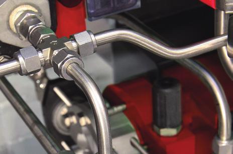

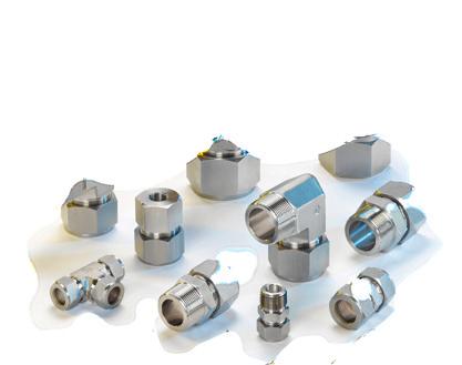
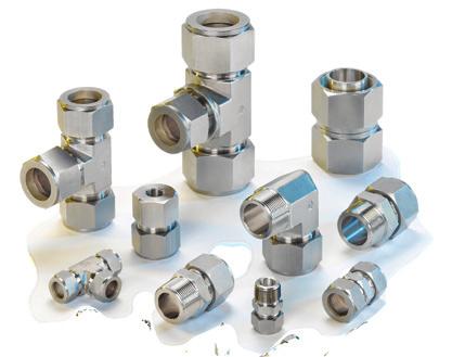

1 COMPRESSION UBE FIINGS CONNECORS 1/16 HROUGH 2 2 MM HROUGH 50 MM

 and fitting body using the mechanical force created by rotating the nut clockwise.")
2 LE-LOK HO OES I ORK? LE-LOK UBE FIINGS ESCRIPION CONNECORS he LE-LOK tube fitting is a mechanism used both to seal and to grip tubing. he mechanical advantage and geometry of this kind of fitting produces a leak-tight assembly. o assemble, simply insert the tube into the complete assembly until the tube bottoms-out against the shoulder of the fitting body (1). he two ferrules are driven forward between the nut (4) and fitting body using the mechanical force created by rotating the nut clockwise. he back ferrule (3) is driven against the tapered rear of the front ferrule (2) and the front ferrule is driven by force into the tapered mouth of the body. he rear ferrule is swaged radially inwards on the tube while lifting the front ferrule out to form a full-faced seal on the tapered surface of the body. he 11/4 turn of the nut from the hand tight position assures consistent drive of the sealing members. his ensures an effective seal against high pressure as well as ultra high vacuum conditions. he HM-LE GROUP has produced high quality tube and pipe fittings in various materials for high pressure applications since its establishment in s a result of tremendous efforts in research and development during the last five decades, HM-LE has gained an excellent reputation as a leading manufacturer of high pressure instrumentation products. he LE-LOK range of connectors has been developed to fill the rapidly increasing demand for tube fittings suitable for high pressure use in environments such as petrochemical, fluid, power, nuclear, electronic, as well as other major industrial settings. LE-LOK tube fittings have been carefully manufactured to withstand the persistent demands for high-performance tube fittings. Each one has passed a stringent tolerance test for high pressure, impulse, vibration, vacuum and temperature. hese precision-machined fittings are manufactured to exacting standards, employing the most modern state-of-the-art computerized automation. ll LE-LOK fittings are backed by HM-LE s commitment to the highest quality-control standards and skilled craftsmanship. 4 ube UBE FIINGS CONSISS OF FOUR PRS: 1. BOY 2. FRON FERRULE 3. BCK FERRULE 4. NU


3 LE-LOK FIINGS INSLLION INSRUCIONS LE-LOK fittings are supplied, assembled and finger tight. isassembly before use can allow the entry of dirt or other particles. Insert the tubing into the LE-LOK fitting. Check that the tube rests firmly on the fitting shoulder and that the nut is finger tight. t this point it is recommended that a scribe mark be drawn on the hex of the nut extending onto the fitting body. his mark will serve as an indicator for the starting point and proper pull-up. RESSEMBLY INSRUCIONS LE-LOK connections may be disconnected and remade repeatedly, without the loss of the leaktight seal. 1. Before disconnecting, mark the position of the nut in relation to the fitting body. 2.o reassemble, use a wrench to tighten the nut to the original position. 3.ighten slightly with a wrench until a slight rise in torque is felt. UBE CUING wo differnet methods can be used to cut tubes 1. ube Cutter 2. Hacksaw UBE CUER o attain a leak free connection, the tubing must be cut squarely. good quality tube cutter with an appropriate blade for tubing material is recommended. o not try to reduce the time of cutting by taking deep cuts with each turn of the cutter. his will work harden the tube. he end of the tube must be deburred to avoid damage to the fitting and to ensure that the tube reaches the bottom of the fitting. INSPECION GUGE Use: his is a No-Go gauge and should be used as follows: 1. Make up the fitting according to the following instructions: 1/4 inch (6mm), 3/8 inch, 1/2 inch (12mm) make up 1-1/4 turns from the finger tight position. 2. Check gap between nut and body, using the appropriate sized gauge. If the gauge slides easily into the gap, tighten the nut further until gauge cannot enter the gap. Gauge enters gap...no good, tighten further CONNECORS ighten the nut. 1-1/4 turns of the nut are required for 1/4 (6 mm) and higher (see Fig. ). 3/4 turn of the nut is required for 3/16 (4 mm) and lower (see Fig. B). HCKS CUING In order to cut the tube with a hacksaw and get square ends, the tube must be cut with guide blocks. his method of cutting necessitates deburring of the tube ends. arning o not hold the tube in a vise in the place where it will be inserted into the fitting (the vise will leave a mark on the tube that may cause leaks, and might cause ovality). Gauge does not enter gap... Good For Gauge : see page 91. Figure UBE HNLING Scratches on the tube might cause leaks. It is, therefore, important to handle the tube carefully to reduce the risk of leaks. SOME PRECUIONS O BE KEN 1.ubes must not be dragged on the floor. 2.ubes must not be dragged out of a tubing rack, especially in cases of large O.. tubes. Figure B COPPER UBING If using copper tubing from a roll, hold the end of the tube and roll the roll outwards, allowing the tubing to lie on a flat surface. HM-LE VNCE CONROL ECHNOLOGY 9
 (2) Material Batch LE-LOK INCH FIINGS: ee & Elbow: (See Fig. 3) Straight Fittings: (see Fig. 4) Body: Shoulder marked: LE-LOK 316 V2 (2) Fig.")


4 LE-LOK FIINGS INSLLION INSRUCIONS PHYSICL IFFERENCES N MRKINGS LE-LOK MERIC FIINGS: ee & Elbow (see Fig. 1) Body marked: MM Straight Connectors: (see Fig. 2) LE-LOK 316 6M S8 Fig. 1 Back side MM (1) (2) Material Batch LE-LOK INCH FIINGS: ee & Elbow: (See Fig. 3) Straight Fittings: (see Fig. 4) Body: Shoulder marked: LE-LOK 316 V2 (2) Fig. 1 Front side Body: Stepped shoulder Marked: LE-LOK 316 V1 (2) Nut: (see Figs.1 & 2) Stepped shoulder Marked: LE-LOK 316 6M (1) S8 (2) LE-LOK 316 V1 Stepped Shoulder Fig. 2 Stepped Shoulder Nut: (See Fig. 3 & 4): Shoulder marked LE-LOK 316 1/2 (1) BU2 (2) UBING FOR LE-LOK FIINGS In order to assure maximum fitting reliability and performance, great care should be given when selecting the tubing for each application. UBE SELECION Four variables must be considered when ordering tube for use with LE-LOK fittings: 1. Material 2. ube wall thickness 3. ube surface finish 4. ube hardness ubing should comply with standard SM 213 or SM 269, be seamless, and fully annealed. he tube must be free of scratches and suitable for bending and flaring. UBE O.. OLERNCES 1/16-1/8 2mm - 3 mm 3/16-1 1/4 4mm - 25 mm 1 1/2-2 38mm - 50 mm ± ± ± mm mm mm LE-LOK 316 1/2 BU2 LE-LOK 316 V2 he ovality of twice the O.. tolerance is not suitable for LE-LOK fittings. he tube must be reasonably round. he ends of the tube must be free of burrs. ubing hardness: he hardness of the tube must be lower than the hardness of the fitting material. he hardness must not exceed Rockwell 90 HRB (200HV). Fig. 3 Back side Fig. 3 Front side Fig. 4 (1) (2) Material Batch HIGH SFEY In applications where severe conditions and high pressure exist, we recommend the following installation procedures: 1. Check that the nut is finger tight. 2. Insert the tube (up to the shoulder). 3. Rotate the nut with a wrench until the tube does not rotate freely. 4. Mark the position of the nut. 5. Rotate the nut 1-1/4 turns. his method ensures that even if the tube O.. is at the minimum tolerance, the ferrules will be in contact with the tube for the full 1-1/4 rotation. 10 COMPRESSION UBE FIINGS
5 BLE 1: SINLESS SEEL INCH UBING ubing O.. LL HICKNESS OF UBE IN INCH inch / / / / / / / / / / / / nnealed 304 or 316 stainless steel tubing complying with SM 213, 269 or equivalent specifications. For metal temp. from -20 F F (-29 C - 37 C). Suggested ordering information: Fully annealed high quality (ype 304 or 316) stainless steel hydraulic tubing SM 269 or 213 or equivalent, seamless or welded and drawn with a hardness of 90HRB (200HV) or less. ubing should be without scratches and suitable for flaring and bending. CONNECORS BLE 2: SINLESS SEEL MERIC UBING ubing O.. LL HICKNESS OF UBE IN MM mm nnealed 304 or 316 stainless steel tubing complying with SM 213, 269 or equivalent specifications. For metal temp. from -20 F F (-29 C - 37 C). Suggested ordering information: Fully annealed high quality (ype 304 or 316) stainless steel hydraulic tubing SM 269 or 213 or equivalent, seamless or welded and drawn with a hardness of 90HRB (200HV) or less. ubing should be without scratches and suitable for flaring and bending. RNING! he system designer and user have the sole responsibility to select products suitable for their special application requirements and to ensure the proper installation, operation and maintenance of the product. Please consider application details, material compatibility and product ratings when making your selection. Improper selection or use of products can cause property damage or personal injury. HM-LE VNCE CONROL ECHNOLOGY 11
6 UBING BLE 3: COPPER UBING LL HICKNESS OF UBE IN INCHES ubing O mm inch 2 1/ / / / / / / / / nnealed copper seamless tubing complying with SM B68 and SM B75 specified in temper designation 060. Based on ultimate tensile strength of 30,000 psi (2067 bar). For metal temperatures from -20 C to 37 C). Suggested ordering information: High quality soft annealed seamless copper tubing SM B75 or equivalent. BLE 4: FCORS USE O EERMINE LLOBLE PRESSURE HIGHER EMPERURES F C.I.S.I. 316 Copper o determine allowable pressure at higher temperatures, multiply allowable working pressure from ables 1 & 2 & 3 by factor shown in able 4. For example: he allowable pressure for ype 316 stainless steel, size 1/2 O x.049 wall at 800 F (427 C) would be equivalent to 3750 psi x 0.79 = psi. BLE 5: GS PPLICION UBING INCH MERIC ubing O.. Min. Nominal all hickness ubing O.. Min. Nominal all hickness 1/ mm 0.8 mm 3/ mm 0.8 mm 1/ mm 1.0 mm 5/ mm 1.0 mm 3/ mm 1.0 mm 1/ mm 1.2 mm 5/ mm 1.5 mm 3/ mm 1.5 mm 7/ mm 1.8 mm mm 2.0 mm 1 1/ mm 2.2 mm 1 1/ mm 3.5 mm mm 5.0 mm Gases are characterized by small molecules, which can escape through the smallest leak path. For gas applications, we recommend to select tubing with greater wall thickness. able 5 shows the recommended wall thicknesses for greater safety and efficiency. RNING! For Your Safety he system designer and user have the sole responsibility to select products suitable for their special application requirements and to ensure the proper installation, operation and maintenance of the product. Please consider application details, material compatibility and product ratings when making your selection. Improper selection or use of products can cause property damage or personal injury. 12 COMPRESSION UBE FIINGS
7 Pressure Ratings for HM-LE ube Fittings o ensure leak-tight systems, it is important to carefully select high-quality tubing (see page 11 - allowable working pressure). Pressure Ratings for End Fittings per SE J1926 (LOB) Surrounding emperature Pressure ratings are based on SE J1926 at surrounding temperature. Pipe End hread (NP and ISO 7) Pressure Ratings llowable pressure for male and female tapered pipe thread ends: Stainless Steel 316 and Brass. BLE 6: PRESSURE RINGS BLE 7: PRESSURE RINGS CONNECORS NP / ISO PIPE SIZE Stainless Steel 316 Brass Male Female Male Female (LOB) SE J1926 hread Size Nonpositionable Stainless Steel 316 Positionable inch psi 1/ / / / / / / / Note: If the pressure on the LE-LOK end is higher than the pipe side, then the pipe side needs a heavier wall thickness of the tapered pipe thread side. inch psi 5/ / / / / / / / / / / / Note: 37 FLRE (N) and LO ends can have lower pressure. O-Seal Pressure Ratings (page 45) Stainless steel 316 O-seal fittings up to 1 and 25 mm are rated to 3000 psi. Positionable, ISO/BSP Parallel hread (G) Pressure Ratings Pressure ratings are at surrounding temperature. BLE 8: PRESSURE RINGS (G) ISO / BSPP Male Pipe Size Stainless Steel 316 inch psi 1/ / / / / HM-LE VNCE CONROL ECHNOLOGY 13
8 INEX BCK FERRULE 760 LB 16 FEMLE CONNECOR 766 LG 30 UBE SOCKE EL UNION 768 L 48 FRON FERRULE 760 LF 16 REUCER 767 L 31 MLE ELBO 769 L 49 UBE INSER 760 LI 17 REUCING POR CONNECOR 767 LM 34 MLE ELBO 769 LR 51 NU 761 L 17 POR CONNECOR 767 LP 35 MLE PIPE EL ELBO 769 LN 52 UNION 762 L 18 MLE CONNECOR 768 L 36 UBE SOCKE EL ELBO 769 L 53 REUCING UNION 763 L 19 MLE CONNECOR 768 LR 39 REUCING ELBO 769 L 53 UNION EE 764 L 21 MLE CONNECOR 768 LG 41 FEMLE ELBO 770 L 54 REUCING EE 764 LR 22 MLE CONNECOR 768 LOK 43 MLE RUN EE 771 L 55 UNION ELBO 765 L 24 MLE CONNECOR 768 LOB 44 FEMLE RUN EE 771 LF 56 REUCING UNION ELBO 765 LR 25 MLE CONNECOR 768 LOP 46 MLE BRNCH EE 772 L 57 FEMLE CONNECOR 766 L 26 MLE CONNECOR 768 LO 47 FEMLE BRNCH EE 772 LF 58 FEMLE CONNECOR 766 LR 28 MLE PIPE EL CONNECOR 768 LN 47 BULKHE UNION 774 L 59
9 BULKHE FEMLE CONNECOR 774 LF 60 MLE PER UBE O PIPE 739 LMG 71 UNION 962 L 78 BULKHE REUCER 774 L 60 EL PER UBE O PIPE 739 LN 72 REUCING UNION 963 L 78 BULKHE MLE CONNECOR 774 LM 61 SOCKE EL PER 739 L 72 UNION EE 964 L 78 CONNECORS BULKHE REUCING UNION 775 L 62 MLE PER 739 LMOB 73 POSIIONBLES 79 UNION CROSS 7102 L 63 LE-LOK O N PER 761 LFL 74 UNION IELECRIC 762 L ielectric 86 CP 7108 L 64 LE-LOK O N UNION 762 LFL 74 MLE CONNECOR 768 LC 88 PLUG 7121 L 65 LE-LOK O N BULKHE UNION 774 LFL 74 LLOY 400 CONNECOR 89 FEMLE PER UBE O PIPE 739 LF 66 MLE PER UBE O N 739 LFL 75 LLOY C-276 CONNECOR 91 MLE PER UBE O PIPE 739 LM 68 PRLLEL HRES SELING 76 SUPER UPLEX 2507 CONNECOR 95 MLE PER UBE O PIPE 739 LMR 70 MLE NU 961 L 78 CCESSORIES 95 LE-LOK MERIL ESCRIPION SOP COLLR 99 EXMPLE: 768L Material escription 1/4 X 1/4 SS - Stainless Steel 316 B - Brass M - lloy 400 HC - lloy C-276 ll orders should include material description and ordering information (see product table). HM-LE VNCE CONROL ECHNOLOGY 15


10 760 LB BCK FERRULE 760 LF FRON FERRULE MERIC mm 760LB _ 2 2 INCH inch mm 760LB _ 1/16 1/ MERIC mm 760LF _ 2 2 INCH inch mm 760LF _ 1/16 1/ LB _ LB _ 1/8 1/ LF _ LF _ 1/8 1/ LB _ LB _ 3/16 3/ LF _ LF _ 3/16 3/ LB _ LB _ 1/4 1/ LF _ LF _ 1/4 1/ LB _ LB _ 5/16 5/ LF _ LF _ 5/16 5/ LB _ LB _ 3/8 3/ LF _ LF _ 3/8 3/ LB _ LB _ 1/2 1/ LF _ LF _ 1/2 1/ LB _ LB _ 5/8 5/ LF _ LF _ 5/8 5/ LB _ LB _ 3/4 3/ LF _ LF _ 3/4 3/ LB _ LB _ 7/8 7/ LF _ LF _ 7/8 7/ LB _ LB _ LF _ LF _ LB _ LB _ 1 1/4 * 1 1/ LF _ LF _ 1 1/4 * 1 1/ LB _ LB _ 1 1/2 * 1 1/ LF _ LF _ 1 1/2 * 1 1/ LB _ LB _ 2 * LF _ LF _ 2 * LB _ 38 * LF _ 38 * LB _ 50 * LF _ 50 * 50 *ithout Ferrule Set. *ithout Ferrule Set. FERRULE SES ll LE-LOK Ferrules are available as sets. Ferrule sets simplify stocking and assembly. Ferrule sets prevent damage of single ferrules during shipping. he back and front ferrules are arranged as pairs in the set; ready for easy assembly. Note: Can be supplied also with Nuts. Example: 760LNS SS 1/4 for Ferrule Sets EXMPLE: 760LS SS 1/4 SS = Stainless Steel 316 B = Brass M = lloy 400 HC = lloy C-276 = PFE he O.. size is always the first to be described Ferrules Material imensions are for reference only, and are subject to change without notice. 16 COMPRESSION UBE FIINGS

11 760 LI UBE INSER MERIC 1 ube I.. mm mm mm 760LI _ 6 X LI _ 8 X LI _ 10 X LI _ 12 X LI _ 12 X INCH 1 ube I.. inch mm inch mm inch mm 760LI _ 3/16 X 1/8 3/ / LI _ 1/4 X 1/8 1/ / LI _ 1/4 X / LI _ 1/4 X 3/16 1/ / LI _ 5/16 X 1/8 5/ / LI _ 5/16 X 3/16 5/ / LI _ 5/16 X 1/4 5/ / LI _ 3/8 X 3/16 3/ / LI _ 3/8 X 1/4 3/ / LI _ 1/2 X 1/4 1/ / LI _ 1/2 X 3/8 1/ / LI _ 5/8 X 3/8 5/ / LI _ 5/8 X 1/2 5/ / LI _ 3/4 X 1/2 3/ / LI _ 3/4 X 5/8 3/ / LI _ 1 X 3/ / CONNECORS 761 L NU MERIC mm mm mm 761L _ L _ L _ L _ L _ L _ L _ L _ L _ L _ L _ L _ L _ L _ L _ L _ inch 54.0 L INCH inch mm inch inch mm 761L _ 1/16 1/ / L _ 1/8 1/ / L _ 3/16 3/ / L _ 1/4 1/ / L _ 5/16 5/ / L _ 3/8 3/ / L _ 1/2 1/ / L _ 5/8 5/ L _ 3/4 3/ / L _ 7/8 7/ / L _ / L _ 1 1/4 1 1/ / L _ 1 1/2 1 1/ / L _ L "" - imension is minimum opening. imensions are for reference only, and are subject to change without notice. HM-LE VNCE CONROL ECHNOLOGY 17
12 762 L UNION UBE (MERIC) O UBE (MERIC) N L I mm mm mm mm mm mm 762L _ L _ L _ L _ L _ L _ L _ L _ L _ L _ L _ L _ L _ L _ L _ 38 * L _ 50 * inch UBE (INCH) O UBE (INCH) N L I inch mm inch mm inch inch mm inch mm inch mm 762L _ 1/16 1/ / L _ 1/8 1/ / L _ 3/16 3/ / L _ 1/4 1/ / L _ 5/16 5/ / L _ 3/8 3/ / L _ 1/2 1/ / L _ 5/8 5/ / L _ 3/4 3/ / L _ 7/8 7/ / L _ / L _ 1 1/4 *1 1/ / L _ 1 1/2 *1 1/ / L _ 2 * / * Including low friction paste, see page 91 - imension is minimum opening. imensions are for reference only, and are subject to change without notice. 18 COMPRESSION UBE FIINGS
13 763 L REUCING UNION UBE (MERIC) O UBE (MERIC) 1 N L I I1 mm mm mm mm mm mm mm mm 763L _ 3 X L _ 6 X L _ 6 X L _ 6 X L _ 8 X L _ 10 X L _ 10 X L _ 12 X L _ 12 X L _ 12 X L _ 16 X L _ 16 X L _ 18 X L _ 25 X L _ 25 X L _ 38 X 20 * L _ 38 X 25 * CONNECORS UBE (MERIC) O UBE (INCH) 1 N L I I1 mm inch mm mm mm mm mm mm 763L _ 2 X 1/4 2 1/ L _ 3 X 1/8 3 1/ L _ 4 X 1/8 4 1/ L _ 4 X 1/4 4 1/ L _ 6 X 1/8 6 1/ L _ 6 X 1/4 6 1/ L _ 6 X 5/16 6 5/ L _ 8 X 1/8 8 1/ L _ 8 X 1/4 8 1/ L _ 8 X 3/8 8 3/ L _ 10 X 1/8 10 1/ L _ 10 X 1/4 10 1/ L _ 10 X 5/ / L _ 10 X 3/8 10 3/ L _ 12 X 5/ / L _ 12 X 3/8 12 3/ L _ 12 X 1/2 12 1/ L _ 15 X 1/2 15 1/ L _ 16 X 5/8 16 5/ L _ 18 X 3/4 18 3/ * Including low friction paste, see page 91 - imension is minimum opening. imensions are for reference only, and are subject to change without notice. Cont d next page HM-LE VNCE CONROL ECHNOLOGY 19
14 763 L REUCING UNION (Cont d) UBE (INCH) O UBE (INCH) 1 ube O. N L I I1 inch mm inch mm inch mm inch inch mm inch mm inch mm inch mm 763L _ 1/8 X 1/16 1/ / / L _ 3/16 X 1/16 3/ / / L _ 3/16 X 1/8 3/ / / L _ 1/4 X 1/16 1/ / / L _ 1/4 X 1/8 1/ / / L _ 1/4 X 3/16 1/ / / L _ 5/16 X 1/8 5/ / / L _ 5/16 X 1/4 5/ / / L _ 3/8 X 1/16 3/ / / L _ 3/8 X 1/8 3/ / / L _ 3/8 X 1/4 3/ / / L _ 3/8 X 5/16 3/ / / L _ 1/2 X 1/8 1/ / / L _ 1/2 X 1/4 1/ / / L _ 1/2 X 3/8 1/ / / L _ 5/8 X 3/8 5/ / / L _ 5/8 X 1/2 5/ / / L _ 3/4 X 1/4 3/ / / L _ 3/4 X 3/8 3/ / / L _ 3/4 X 1/2 3/ / / L _ 3/4 X 5/8 3/ / / L _ 1 X 1/ / / L _ 1 X 3/ / / COMPRESSION UBE FIINGS
15 764 L UNION EE LL UBE (MERIC) rench Flat N E I mm mm inch mm mm mm mm 764L _ / L _ / L _ / L _ / L _ / L _ / L _ / L _ / L _ / L _ / L _ / L _ / L _ / L _ / L _ 38 * L _ 50 * / CONNECORS LL UBE (INCH) rench Flat N E I inch mm inch mm inch mm inch mm inch mm inch mm 764L _ 1/16 1/ / L _ 1/8 1/ / L _ 3/16 3/ / L _ 1/4 1/ / L _ 5/16 5/ / L _ 3/8 3/ / L _ 1/2 1/ / L _ 5/8 5/ / L _ 3/4 3/ / L _ 7/8 7/ / L _ / L _ 1 1/4 *1 1/ / L _ 1 1/2 *1 1/ L _ 2 * / * Including low friction paste, see page 91 - imension is minimum opening. imensions are for reference only, and are subject to change without notice. HM-LE VNCE CONROL ECHNOLOGY 21
16 764 LR REUCING EE LL UBE (MERIC) LL UBE (INCH) 1 ube O. 1 E E1 I I1 rench Flat mm mm mm mm mm mm mm inch mm mm mm 764LR_8MMX8MMX6MM / LR_10MMX10MMX6MM / LR_12MMX12MMX6MM / LR_12MMX12MMX10MM / LR_14MMX14MMX10MM / LR_18MMX18MMX12MM / LR_50MMX50MMX38MM *50 * / E E1 I I1 rench Flat inch mm inch mm inch mm inch mm inch mm inch mm inch mm inch mm inch mm inch mm 764LR_1/4 X 1/4 X 1/8 1/ / / LR_3/8 X 3/8 X 1/4 3/ / / LR_1/2 X 1/2 X 1/4 1/ / / LR_1/2 X 1/2 X 3/8 1/ / / LR_5/8 X 5/8 X 3/8 5/ / / LR_3/4 X 3/4 X 1/4 3/ / / LR_3/4 X 3/4 X 3/8 3/ / / LR_3/4 X 3/4 X 1/2 3/ / / LR_1 X 1 X 3/ / / LR_1 X 1 X 1/ / / LR_1 X 1 X 3/ / / LR_1 1/4 X 1 1/4 X 1 *1 1/ / LR_1 1/2 X 1 1/2 X 1 *1 1/ * Including low friction paste, see page 91 N N N1 N1 - imension is minimum opening. imensions are for reference only, and are subject to change without notice. Cont d next page 22 COMPRESSION UBE FIINGS

 1 ube O.")

17 764 LR REUCING EE (Cont d) LL UBE (INCH) 1 ube O. E E1 I I1 rench Flat inch mm inch mm inch mm inch mm inch mm inch mm inch mm inch mm inch mm inch mm 764LR _ 1/4 X 1/8 X 1/4 1/ / / LR _ 3/8 X 1/4 X 3/8 3/ / / LR _ 1/2 X 1/4 X 1/2 1/ / / LR _1/2 X 3/8 X 1/2 1/ / / LR _ 3/4 X 3/8 X 3/4 3/ / / N N1 CONNECORS LL UBE (INCH) 1 ube O. E E1 I I1 rench Flat inch mm inch mm inch mm inch mm inch mm inch mm inch mm inch mm inch mm inch mm 764LR_1/2 X 3/8 X 3/8 1/ / / LR_5/8 X 3/8 X 3/8 5/ / / LR_3/4 X 3/8 X 3/8 3/ / / N N1 LL UBE (INCH) 1 ube O. 2 ube O. E E1 E2 I I1 I2 rench Flat - imension is minimum opening. imensions are for reference only, and are subject to change without notice. N N1&N2 inch mm inch mm inch mm inch mm inch mm inch mm inch mm inch mm inch mm inch mm inch mm inch mm inch mm 764LR_5/8 X 1/2 X 3/8 5/ / / / LR_3/4 X 1/2 X 3/8 3/ / / / LR_1 X 3/4 X 3/ / / / HM-LE VNCE CONROL ECHNOLOGY 23

18 765 L UNION ELBO UBE (MERIC) O UBE (MERIC) rench Flat N E I mm mm inch mm mm mm mm 765L _ / L _ / L _ / L _ / L _ / L _ / L _ / L _ / L _ / L _ / L _ / L _ / L _ / L _ 38 * L _ 50 * / UBE (INCH) O UBE (INCH) rench Flat N E I inch mm inch mm inch mm inch mm inch mm inch mm 765L _ 1/16 1/ / L _ 1/8 1/ / L _ 3/16 3/ / L _ 1/4 1/ / L _ 5/16 5/ / L _ 3/8 3/ / L _ 1/2 1/ / L _ 5/8 5/ / L _ 3/4 3/ / L _ 7/8 7/ / L _ / L _ 1 1/4 *1 1/ / L _ 1 1/2 *1 1/ L _ 2 * / * Including low friction paste, see page 91 - imension is minimum opening. imensions are for reference only, and are subject to change without notice. 24 COMPRESSION UBE FIINGS
 O UBE (INCH) 1 ube O.")

19 765 LR REUCING UNION ELBO UBE (MERIC) O UBE (INCH) 1 ube O. E E1 I I1 rench Flat mm inch mm mm mm mm mm in mm mm mm 765LR _ 6 X 1/4 6 1/ / LR _ 8 X 1/4 8 1/ / N N1 CONNECORS UBE (INCH) O UBE (INCH) 1 ube O. E E1 I I1 rench Flat in mm in mm in mm in mm in mm in mm in mm in mm in mm in mm 765LR _ 3/8 X 1/4 3/ / / LR _ 5/8 X 3/8 5/ / / N N1 - imension is minimum opening. imensions are for reference only, and are subject to change without notice. HM-LE VNCE CONROL ECHNOLOGY 25
20 766 L FEMLE CONNECOR UBE (MERIC) O FEMLE NP HRE (NP) N L I mm inch mm mm mm mm mm 766L _ 3 X 1/8 3 1/ L _ 3 X 1/4 3 1/ L _ 4 X 1/8 4 1/ L _ 6 X 1/8 6 1/ L _ 6 X 1/4 6 1/ L _ 6 X 3/8 6 3/ L _ 6 X 1/2 6 1/ L _ 8 X 1/8 8 1/ L _ 8 X 1/4 8 1/ L _ 8 X 3/8 8 3/ L _ 8 X 1/2 8 1/ L _ 10 X 1/4 10 1/ L _ 10 X 3/8 10 3/ L _ 10 X 1/2 10 1/ L _ 12 X 1/4 12 1/ L _ 12 X 3/8 12 3/ L _ 12 X 1/2 12 1/ L _ 15 X 1/2 15 1/ L _ 16 X 1/2 16 1/ L _ 20 X 1/2 20 1/ L _ 20 X 3/4 20 3/ L _ 22 X 3/4 22 3/ L _ 22 X L _ 25 X 3/4 25 3/ L _ 25 X imension is minimum opening. imensions are for reference only, and are subject to change without notice. Cont d next page 26 COMPRESSION UBE FIINGS
21 766 L FEMLE CONNECOR (Cont d) UBE (INCH) O FEMLE NP HRE (NP) Hex Flat N L I inch mm inch inch mm inch inch mm inch mm inch mm 766L _ 1/16 X1/16 1/ / / L _ 1/16 X 1/8 1/ / / L _ 1/8 X 1/8 1/ / / L _ 1/8 X 1/4 1/ / / L _ 3/16 X 1/8 3/ / / L _ 1/4 X 1/8 1/ / / L _ 1/4 X 1/4 1/ / / L _ 1/4 X 3/8 1/ / / L _ 1/4 X 1/2 1/ / / L _ 5/16 X 1/8 5/ / / L _ 5/16 X 1/4 5/ / / L _ 3/8 X 1/8 3/ / / L _ 3/8 X 1/4 3/ / / L _ 3/8 X 3/8 3/ / / L _ 3/8 X 1/2 3/ / / L _ 3/8 X 3/4 3/ / / L _ 1/2 X 1/4 1/ / / L _ 1/2 X 3/8 1/ / / L _ 1/2 X 1/2 1/ / / L _ 1/2 X 3/4 1/ / / L _ 5/8 X 3/8 5/ / / L _ 5/8 X 1/2 5/ / / L _ 5/8 X 3/4 5/ / / L _ 3/4 X 1/2 3/ / / L _ 3/4 X 3/4 3/ / / L _ 7/8 X 3/4 7/ / / L _ 1 X 3/ / / L _ 1 X / L _ 1 1/4 X 1 1/4 *1 1/ / / L _ 1 1/2 X 1 1/2 *1 1/ / / L _ 2 X 2 * / CONNECORS * Including low friction paste, see page 91 - imension is minimum opening. imensions are for reference only, and are subject to change without notice. HM-LE VNCE CONROL ECHNOLOGY 27
22 766 LR FEMLE CONNECOR UBE (MERIC) O FEMLE ISO PERE HRE (ISO) N L I mm inch mm mm mm mm mm 766LR _ 3 X 1/8 3 R-1/ LR _ 6 X 1/8 6 R-1/ LR _ 6 X 1/4 6 R-1/ LR _ 6 X 3/8 6 R-3/ LR _ 6 X 1/2 6 R-1/ LR _ 8 X 1/8 8 R-1/ LR _ 8 X 1/4 8 R-1/ LR _ 8 X 3/8 8 R-3/ LR _ 8 X 1/2 8 R-1/ LR _ 10 X 1/8 10 R-1/ LR _ 10 X 1/4 10 R-1/ LR _ 10 X 3/8 10 R-3/ LR _ 10 X 1/2 10 R-1/ LR _ 12 X 1/8 12 R-1/ LR _ 12 X 1/4 12 R-1/ LR _ 12 X 3/8 12 R-3/ LR _ 12 X 1/2 12 R-1/ LR _ 12 X 3/4 12 R-3/ LR _ 15 X 3/8 15 R-3/ LR _ 15 X 1/2 15 R-1/ LR _ 20 X 1/2 20 R-1/ LR _ 20 X 3/4 20 R-3/ LR _ 22 X 3/4 22 R-3/ LR _ 22 X 1 22 R LR _ 25 X 3/4 25 R-3/ LR _ 25 X 1 25 R Reference Specifications: IN BS -21 JIS -B0203 ISO -7/1-BSP- esignation: Marking LR on Hex. - imension is minimum opening. imensions are for reference only, and are subject to change without notice. Cont d next page 28 COMPRESSION UBE FIINGS
23 766 LR FEMLE CONNECOR (Cont d) UBE (INCH) O FEMLE ISO PERE HRE (ISO) Hex Flat N L I inch mm inch inch mm inch inch mm inch mm inch mm 766LR _ 1/16 X1/16 1/ R-1/ / LR _ 1/16 X 1/8 1/ R-1/ / LR _ 1/8 X 1/8 1/ R-1/ / LR _ 1/8 X 1/4 1/ R-1/ / LR _ 3/16 X 1/8 3/ R-1/ / LR _ 1/4 X 1/8 1/ R-1/ / LR _ 1/4 X 1/4 1/ R-1/ / LR _ 1/4 X 3/8 1/ R-3/ / LR _ 1/4 X 1/2 1/ R-1/ / LR _ 5/16 X 1/4 5/ R-1/ / LR _ 3/8 X 1/8 3/ R-1/ / LR _ 3/8 X 1/4 3/ R-1/ / LR _ 3/8 X 3/8 3/ R-3/ / LR _ 3/8 X 1/2 3/ R-1/ / LR_ 1/2 X 1/4 1/ R-1/ / LR _ 1/2 X 3/8 1/ R-3/ / LR_ 1/2 X 1/2 1/ R-1/ / LR _ 5/8 X 1/2 5/ R-1/ / LR _ 3/4 X 1/2 3/ R-1/ / LR _ 3/4 X 3/4 3/ R-3/ / LR _ 1 X 3/ R-3/ / LR _ 1 X R / CONNECORS Reference Specifications: IN BS -21 JIS -B0203 ISO -7/1-BSP- esignation: Marking LR on Hex. - imension is minimum opening. imensions are for reference only, and are subject to change without notice. HM-LE VNCE CONROL ECHNOLOGY 29
24 766 LG FEMLE CONNECOR UBE (MERIC) O FEMLE ISO PRLLEL HRE (ISO) 1 B b Min a Min N L I mm inch mm mm mm mm mm mm mm mm mm 766LG _ 3 X 1/4 3 G-1/ LG _ 6 X 1/8 6 G-1/ LG _ 6 X 1/4 6 G-1/ LG _ 6 X 3/8 6 G-3/ LG _ 6 X 1/2 6 G-1/ LG _ 8 X 1/4 8 G-1/ LG _ 8 X 3/8 8 G-3/ LG _ 8 X 1/2 8 G-1/ LG _ 10 X 1/4 10 G-1/ LG _ 10 X 3/8 10 G-3/ LG _ 10 X 1/2 10 G-1/ LG _ 12 X 1/4 12 G-1/ LG _ 12 X 3/8 12 G-3/ LG _ 12 X 1/2 12 G-1/ LG _ 20 X 1/2 20 G-1/ LG _ 22 X 1/2 22 G-1/ UBE (INCH) O FEMLE ISO PRLLEL HRE (ISO) 1 B b Min a Min N L I inch mm inch inch mm inch mm inch inch mm inch mm inch mm inch mm inch mm inch mm 766LG _ 1/8 X 1/4 1/ G-1/ / LG _ 1/4 X 1/8 1/ G-1/ / LG _ 1/4 X 1/4 1/ G-1/ / LG _ 1/4 X 3/8 1/ G-3/ / LG _ 1/4 X 1/2 1/ G-1/ / LG _ 5/16 X 1/4 5/ G-1/ / LG _ 5/16 X 1/2 5/ G-1/ / LG _ 3/8 X 1/4 3/ G-1/ / LG _ 3/8 X 3/8 3/ G-3/ / LG _ 3/8 X 1/2 3/ G-1/ / LG _ 1/2 X 3/8 1/ G-3/ / LG _ 1/2 X 1/2 1/ G-1/ / Reference Specifications: IN -ISO 228/1 BS JIS -B0202 ISO -228/1-BSP-P esignation: Marking LG on Hex. For Parallel hreads Sealing, see page 76 - imension is minimum opening. imensions are for reference only, and are subject to change without notice. 30 COMPRESSION UBE FIINGS
25 767 L REUCER UBE (MERIC) O SUB (MERIC) 1 N L I mm mm mm mm mm mm mm 767L _ 2 X L _ 3 X L _ 3 X L _ 3 X L _ 4 X L _ 6 X L _ 6 X L _ 6 X L _ 6 X L _ 6 X L _ 8 X L _ 8 X L _ 8 X L _ 10 X L _ 10 X L _ 10 X L _ 10 X L _ 10 X L _ 12 X L _ 12 X L _ 12 X L _ 12 X L _ 12 X L _ 12 X L _ 12 X L _ 12 X L _ 16 X L _ 18 X L _ 18 X L _ 18 X L _ 18 X L _ 18 X L _ 20 X L _ 20 X L _ 20 X L _ 20 X L _ 22 X L _ 22 X L _ 22 X L _ 25 X L _ 25 X CONNECORS - imension is minimum opening. imensions are for reference only, and are subject to change without notice. Cont d next page HM-LE VNCE CONROL ECHNOLOGY 31
26 767 L REUCER (Cont d) UBE (MERIC) O SUB (INCH) 1 N L I mm inch mm mm mm mm mm 767L _ 2 X 1/8 2 1/ L _ 3 X 1/8 3 1/ L _ 3 X 1/4 3 1/ L _ 4 X 1/4 4 1/ L _ 6 X 1/8 6 1/ L _ 6 X 5/16 6 5/ L _ 6 X 3/8 6 3/ L _ 6 X 1/2 6 1/ L _ 8 X 3/8 8 3/ L _ 8 X 1/2 8 1/ L _ 10 X 3/8 10 3/ L _ 10 X 1/2 10 1/ L _ 12 X 1/2 12 1/ L _ 12 X 3/4 12 3/ L _ 18 X 3/4 18 3/ L _ 18 X L _ 25 X HE EXCHNGER EE; INFORMION UNION EE L REUCER L Heat exchanger tee made with Let-Lok tube fittings: - imension is minimum opening. imensions are for reference only, and are subject to change without notice. Cont d next page 32 COMPRESSION UBE FIINGS
27 767 L REUCER (Cont d) UBE (INCH) O SUB (INCH) 1 Hex Flat N L I inch mm inch mm inch mm inch inch mm inch mm inch mm 767L _ 1/16 X 1/8 1/ / / L _ 1/16 X 1/4 1/ / / L _ 1/8 X 1/16 1/ / / L _ 1/8 X 1/8 1/ / / L _ 1/8 X 3/16 1/ / / L _ 1/8 X 1/4 1/ / / L _ 1/8 X 3/8 1/ / / L _ 1/8 X 1/2 1/ / / L _ 3/16 X 1/8 3/ / / L _ 3/16 X 1/4 3/ / / L _ 1/4 X 1/8 1/ / / L _ 1/4 X 3/16 1/ / / L _ 1/4 X 1/4 1/ / / L _ 1/4 X 5/16 1/ / / L _ 1/4 X 3/8 1/ / / L _ 1/4 X 1/2 1/ / / L _ 1/4 X 5/8 1/ / / L _ 1/4 X 3/4 1/ / / L _ 5/16 X 3/8 5/ / / L _ 5/16 X 1/2 5/ / / L _ 3/8 X 1/4 3/ / / L _ 3/8 X 3/8 3/ / / L _ 3/8 X 1/2 3/ / / L _ 3/8 X 5/8 3/ / / L _ 3/8 X 3/4 3/ / / L _ 1/2 X 1/4 1/ / / L _ 1/2 X 3/8 1/ / / L _ 1/2 X 1/2 1/ / / L _ 1/2 X 5/8 1/ / / L _ 1/2 X 3/4 1/ / / L _ 1/2 X 1 1/ / L _ 5/8 X 3/4 5/ / / L _ 5/8 X 7/8 5/ / / L _ 5/8 X 1 5/ / L _ 3/4 X 1/2 3/ / / L _ 3/4 X 1 3/ / L _ 1 X 1 1/ *1 1/ / L _ 1 X 1 1/ *1 1/ / L _ 1 1/4 X 1 1/2 1 1/ *1 1/ / CONNECORS SSEMBLY INSRUCIONS: Reducer tube to stub 767 L *Supplied assembled on tube stub end (1) nut+front & back ferrule. ighten the nut on the body 1/2 a turn with a wrench. Low friction paste, see page imension is minimum opening. imensions are for reference only, and are subject to change without notice. HM-LE VNCE CONROL ECHNOLOGY 1 1/4 URNS 33
28 767 L REUCER (Cont d)eucer (Cont d) UBE (INCH) O SUB (MERIC) 1 N L I inch mm mm inch mm inch inch mm inch mm inch mm 767L _ 1/8 X 6 1/ / L _ 1/4 X 6 1/ / L _ 3/8 X 8 3/ / L _ 3/8 X 12 3/ / LM REUCING POR CONNECOR CONNECS O LE-LOK PORS (MERIC) 1 mm mm mm mm 767LM _ 6 X LM _ 8 X LM _ 10 X LM _ 10 X LM _ 12 X LM _ 12 X LM _ 12 X LM _ 16 X LM _ 38 X 25 * CONNECS O LE-LOK PORS (INCH) 1 inch mm inch mm inch mm inch mm 767LM _ 1/8 X 1/16 1/ / LM _ 1/4 X 1/16 1/ / LM _ 1/4 X 1/8 1/ / LM _ 3/8 X 1/8 3/ / LM _ 3/8 X 1/4 3/ / LM _ 1/2 X 1/4 1/ / LM _ 1/2 X 3/8 1/ / LM _ 3/4 X 1/2 3/ / L L SSEMBLY INSRUCIONS Reducer Port Connector 767 LM ighten the nut. 1-1/4 turns of the nut are required for 1/4 (6 mm) and higher. 3/4 turn of the nut is required for 3/16 (4 mm) and lower. * Including low friction paste, see page 91 - imension is minimum opening. imensions are for reference only, and are subject to change without notice. 1/4 URN 34 COMPRESSION UBE FIINGS
29 767 LP POR CONNECOR CONNECS O LE-LOK PORS (MERIC) mm mm mm 767LP _ LP _ LP _ LP _ LP _ LP _ LP _ LP _ 38 * LP _ 50 * L CONNECORS CONNECS O LE-LOK PORS (INCH) inch mm inch mm inch mm 767LP _ 1/16 1/ LP _ 1/8 1/ LP _ 1/4 1/ LP _ 5/16 5/ LP _ 3/8 3/ LP _ 1/2 1/ LP _ 3/4 3/ LP _ LP _ 1 1/4 *1 1/ LP _ 1 1/2 *1 1/ LP _ 2 * L Port Connector 767LP ighten the nut. 1-1/4 turns of the nut are required for 1/4 (6 mm) and higher. 3/4 turn of the nut is required for 3/16 (4 mm) and lower. 1/4 URN * Supplied assembled with Nuts and Ferrules. Low friction paste, see page 91 - imension is minimum opening. imensions are for reference only, and are subject to change without notice. HM-LE VNCE CONROL ECHNOLOGY 35
30 768 L MLE CONNECOR UBE (MERIC) MLE NP HRE (NP) N L I mm inch mm mm mm mm mm 768L _ 2 X 1/8 2 1/ L _ 3 X 1/8 3 1/ L _ 3 X 1/4 3 1/ L _ 4 X 1/8 4 1/ L _ 4 X 1/4 4 1/ L _ 6 X 1/8 6 1/ L _ 6 X 1/4 6 1/ L _ 6 X 3/8 6 3/ L _ 6 X 1/2 6 1/ L _ 8 X 1/8 8 1/ L _ 8 X 1/4 8 1/ L _ 8 X 3/8 8 3/ L _ 8 X 1/2 8 1/ L _ 10 X 1/8 10 1/ L _ 10 X 1/4 10 1/ L _ 10 X 3/8 10 3/ L _ 10 X 1/2 10 1/ L _ 10 X 3/4 10 3/ L _ 12 X 1/8 12 1/ L _ 12 X 1/4 12 1/ L _ 12 X 3/8 12 3/ L _ 12 X 1/2 12 1/ L _ 12 X 3/4 12 3/ L _ 14 X 1/4 14 1/ L _ 14 X 3/8 14 3/ L _ 14 X 1/2 14 1/ L _ 15 X 1/2 15 1/ L _ 16 X 3/8 16 3/ L _ 16 X 1/2 16 1/ L _ 16 X 3/4 16 3/ L _ 18 X 1/2 18 1/ L _ 18 X 3/4 18 3/ L _ 20 X 1/2 20 1/ L _ 20 X 3/4 20 3/ L _ 22 X 3/4 22 3/ L _ 22 X L _ 25 X 1/2 25 1/ L _ 25 X 3/4 25 3/ L _ 25 X L _ 38 X 1 1/2 *38 1 1/ L _ 50 X 2 * inch * Supplied assembled with Nuts and Ferrules. For low friction paste, see page 91 - imension is minimum opening. imensions are for reference only, and are subject to change without notice. Cont d next page 36 COMPRESSION UBE FIINGS
31 768 L MLE CONNECOR (Cont d) UBE (INCH) MLE NP HRE (NP) N L I inch mm inch inch mm inch inch mm inch mm inch mm 768L _ 1/16 X 1/16 1/ / / L _ 1/16 X 1/8 1/ / / L _ 1/16 X 1/4 1/ / / L _ 1/8 X 1/16 1/ / / L _ 1/8 X 1/8 1/ / / L _ 1/8 X 1/4 1/ / / L _ 1/8 X 3/8 1/ / / L _ 1/8 X 1/2 1/ / / L _ 3/16 X 1/8 3/ / / L _ 3/16 X 1/4 3/ / / L _ 1/4 X 1/16 1/ / / L _ 1/4 X 1/8 1/ / / L _ 1/4 X 1/4 1/ / / L _ 1/4 X 3/8 1/ / / L _ 1/4 X 1/2 1/ / / L _ 1/4 X 3/4 1/ / / L _ 5/16 X 1/8 5/ / / L _ 5/16 X 1/4 5/ / / L _ 5/16 X 3/8 5/ / / L _ 3/8 X 1/8 3/ / / L _ 3/8 X 1/4 3/ / / L _ 3/8 X 3/8 3/ / / L _ 3/8 X 1/2 3/ / / L _ 3/8 X 3/4 3/ / / L _ 3/8 X 1 3/ / L _ 1/2 X 1/8 1/ / / L _ 1/2 X 1/4 1/ / / L _ 1/2 X 3/8 1/ / / L _ 1/2 X 1/2 1/ / / L _ 1/2 X 3/4 1/ / / L _ 1/2 X 1 1/ / CONNECORS Reference Specifications: 60 hread angle Pitch measured in inches runcation of root and crest is flat aper angle 1 47 merican Standard Pipe hread (NP). NP (National Pipe apered) is made according to the specifications outlined in NSI B hermoelement (see Page 38) imension is minimum opening. imensions are for reference only, and are subject to change without notice. Cont d next page HM-LE VNCE CONROL ECHNOLOGY 37
32 768 L MLE CONNECOR (Cont d) UBE (INCH) MLE NP HRE (NP) N L I inch mm inch inch mm inch inch mm inch mm inch mm 768L _ 5/8 X 1/4 5/ / / L _ 5/8 X 3/8 5/ / / L _ 5/8 X 1/2 5/ / / L _ 5/8 X 3/4 5/ / / L _ 3/4 X 3/8 3/ / / L _ 3/4 X 1/2 3/ / / L _ 3/4 X 3/4 3/ / / L _ 3/4 X 1 3/ / L _ 7/8 X 1/2 7/ / / L _ 7/8 X 3/4 7/ / / L _ 7/8 X 1 7/ / L _ 1 X 1/ / / L _ 1 X 3/ / / L _ 1 X / L _ 1 1/4 X 1 *1 1/ / L _ 1 1/4 X 1 1/4 *1 1/ / / L _ 1 1/2 X 1 1/2 *1 1/ / / L _ 2 X 2 * / * Including low friction paste, See page 91 Reference Specifications: 60 hread angle Pitch measured in inches runcation of root and crest is flat aper angle 1 47 merican Standard Pipe hread (NP). NP (National Pipe apered) is made according to the specifications outlined in SNI B hermoelement For ordering: use the catalog number of the selected fitting and add the suffix C. Example: 768 L SS 1/4 x 1/4 C - imension is minimum opening. imensions are for reference only, and are subject to change without notice. 38 COMPRESSION UBE FIINGS
33 768 LR MLE CONNECOR UBE (MERIC) ISO PERE HRE (ISO) N L I mm inch mm mm mm mm mm 768LR _ 2 X 1/8 2 R-1/ LR _ 3 X 1/8 3 R-1/ LR _ 3 X 1/4 3 R-1/ LR _ 4 X 1/8 4 R-1/ LR _ 4 X 1/4 4 R-1/ LR _ 6 X 1/8 6 R-1/ LR _ 6 X 1/4 6 R-1/ LR _ 6 X 3/8 6 R-3/ LR _ 6 X 1/2 6 R-1/ LR _ 8 X 1/8 8 R-1/ LR _ 8 X 1/4 8 R-1/ LR _ 8 X 3/8 8 R-3/ LR _ 8 X 1/2 8 R-1/ LR _ 10 X 1/8 10 R-1/ LR _ 10 X 1/4 10 R-1/ LR _ 10 X 3/8 10 R-3/ LR _ 10 X 1/2 10 R-1/ LR _ 10 X 3/4 10 R-3/ LR _ 12 X 1/4 12 R-1/ LR _ 12 X 3/8 12 R-3/ LR _ 12 X 1/2 12 R-1/ LR _ 12 X 3/4 12 R-3/ LR _ 14 X 1/4 14 R-1/ LR _ 14 X 3/8 14 R-3/ LR _ 15 X 1/2 15 R-1/ LR _ 16 X 1/4 16 R-1/ LR _ 16 X 3/8 16 R-3/ LR _ 16 X 1/2 16 R-1/ LR _ 16 X 3/4 16 R-3/ LR _ 18 X 1/2 18 R-1/ LR _ 18 X 3/4 18 R-3/ LR _ 20 X 1/2 20 R-1/ LR _ 20 X 3/4 20 R-3/ LR _ 22 X 3/4 22 R-3/ LR _ 22 X 1 22 R LR _ 25 X 1/2 25 R-1/ LR _ 25 X 3/4 25 R-3/ LR _ 25 X 1 25 R LR _ 38 X 1 1/2 *38 R-1 1/ LR _ 50 X 2 *50 R inch CONNECORS esignation: Marking LR on Hex Reference Specifications: IN -ISO 2999 BS - 21 JIS - B0203 ISO - 7/1-BSP- hermoelement (See Page 38) * Including low friction paste, see page 91 - imension is minimum opening. imensions are for reference only, and are subject to change without notice. HM-LE VNCE CONROL ECHNOLOGY 39
34 768 LR MLE CONNECOR (Cont d) UBE (INCH) ISO PERE HRE (ISO) N L I inch mm inch inch mm inch inch mm inch mm inch mm 768LR _ 1/8 X 1/8 1/ R-1/ / LR _ 1/8 X 1/4 1/ R-1/ / LR _ 1/4 X 1/8 1/ R-1/ / LR _ 1/4 X 1/4 1/ R-1/ / LR _ 1/4 X 3/8 1/ R-3/ / LR _ 1/4 X 1/2 1/ R-1/ / LR _ 5/16 X 1/8 5/ R-1/ / LR _ 5/16 X 1/4 5/ R-1/ / LR _ 3/8 X 1/8 3/ R-1/ / LR _ 3/8 X 1/4 3/ R-1/ / LR _ 3/8 X 3/8 3/ R-3/ / LR _ 3/8 X 1/2 3/ R-1/ / LR _ 3/8 X 3/4 3/ R-3/ / LR _ 1/2 X 1/4 1/ R-1/ / LR _ 1/2 X 3/8 1/ R-3/ / LR _ 1/2 X 1/2 1/ R-1/ / LR _ 1/2 X 3/4 1/ R-3/ / LR _ 5/8 X 1/2 5/ R-1/ / LR _ 3/4 X 3/4 3/ R-3/ / LR _ 3/4 X 1 3/ R / LR _ 1 X 3/ R-3/ / LR _ 1 X R / LR _ 1 1/4 X 1 1/4 *1 1/ R-1 1/ / * Including low friction paste, See page 91 Reference Specifications: IN -ISO hread angle BS - 21 runcation of root and crest is round JIS - B0203 aper angle 1 47 ISO - 7/1-BSP- esignation: Marking LR on Hex hermoelement (see Page 38) - imension is minimum opening. imensions are for reference only, and are subject to change without notice. 40 COMPRESSION UBE FIINGS
35 768 LG MLE CONNECOR UBE (MERIC) ISO PRLLEL HRE (P-ISO) K N M L I mm inch mm mm mm mm mm mm mm 768LG _ 2 X 1/8 2 G-1/ LG _ 3 X 1/8 3 G-1/ LG _ 3 X 1/4 3 G-1/ LG _ 4 X 1/8 4 G-1/ LG _ 6 X 1/8 6 G-1/ LG _ 6 X 1/4 6 G-1/ LG _ 6 X 3/8 6 G-3/ LG _ 6 X 1/2 6 G-1/ LG _ 8 X 1/8 8 G-1/ LG _ 8 X 1/4 8 G-1/ LG _ 8 X 3/8 8 G-3/ LG _ 8 X 1/2 8 G-1/ LG _ 10 X 1/4 10 G-1/ LG _ 10 X 3/8 10 G-3/ LG _ 10 X 1/2 10 G-1/ LG _ 12 X 1/4 12 G-1/ LG _ 12 X 3/8 12 G-3/ LG _ 12 X 1/2 12 G-1/ LG _ 12 X 3/4 12 G-3/ LG _ 14 X 3/8 14 G-3/ LG _ 14 X 1/2 14 G-1/ LG _ 15 X 3/8 15 G-3/ LG _ 15 X 1/2 15 G-1/ LG _ 15 X 3/4 15 G-3/ LG _ 16 X 3/8 16 G-3/ LG _ 16 X 1/2 16 G-1/ LG _ 16 X 3/4 16 G-3/ LG _ 18 X 1/2 18 G-1/ LG _ 18 X 3/4 18 G-3/ LG _ 20 X 1/2 20 G-1/ LG _ 20 X 3/4 20 G-3/ LG _ 22 X 3/4 22 G-3/ LG _ 22 X 1 22 G LG _ 25 X 3/4 25 G-3/ LG _ 25 X 1 25 G LG _ 38 X1 1/2 *38 G-1 1/ CONNECORS Reference Specifications: esignation: Marking LG on Hex. * Including low friction paste, See page imension is minimum opening. imensions are for reference only, and are subject to change without notice. For Parallel hreads Sealing, see page 76 HM-LE VNCE CONROL ECHNOLOGY 41
36 768 LG MLE CONNECOR (Cont d) UBE (INCH) O ISO PRLLEL HRE (P-ISO) K N M L I inch mm inch inch mm inch mm inch inch mm inch mm inch mm inch mm 768LG _ 1/8 X 1/8 1/ G-1/ / LG _ 1/8 X 1/4 1/ G-1/ / LG _ 1/8 X 3/8 1/ G-3/ / LG _ 1/8 X 1/2 1/ G-1/ / LG _ 3/16 X 1/8 3/ G-1/ / LG _ 1/4 X 1/8 1/ G-1/ / LG _ 1/4 X 1/4 1/ G-1/ / LG _ 1/4 X 3/8 1/ G-3/ / LG _ 1/4 X 1/2 1/ G-1/ / LG _ 5/16 X 1/4 5/ G-1/ / LG _ 5/16 X 3/8 5/ G-3/ / LG _ 3/8 X 1/8 3/ G-1/ / LG _ 3/8 X 1/4 3/ G-1/ / LG _ 3/8 X 3/8 3/ G-3/ / LG _ 3/8 X 1/2 3/ G-1/ / LG _ 1/2 X 1/4 1/ G-1/ / LG _ 1/2 X 3/8 1/ G-3/ / LG _ 1/2 X 1/2 1/ G-1/ / LG _ 1/2 X 3/4 1/ G-3/ / LG _ 5/8 X 3/8 5/ G-3/ mm LG _ 5/8 X 1/2 5/ G-1/ / LG _ 3/4 X 1/2 3/ G-1/ / LG _ 3/4 X 3/4 3/ G-3/ / LG _ 1 X 1/ G-1/ / LG _ 1 X 3/ G-3/ / LG _ 1 X G / esignation: Marking LG on Hex. Reference Specifications: IN - ISO 228/1 BS JIS - B0202 ISO - 228/1-BSP-P For Parallel hreads Sealing, see page hread angle Pitch measured in inches runcation of root and crest is round iameter measured in inches - imension is minimum opening. imensions are for reference only, and are subject to change without notice. 42 COMPRESSION UBE FIINGS
37 768 LOK MLE CONNECOR UBE (MERIC) ISO PRLLEL HRE (P-ISO) K N H L I mm inch mm mm mm mm mm mm mm 768LOK _ 3 X 1/8 3 G-1/ LOK _ 3 X 1/4 3 G-1/ LOK _ 4 X 1/8 4 G-1/ LOK _ 6 X 1/8 6 G-1/ LOK _ 6 X 1/4 6 G-1/ LOK _ 6 X 3/8 6 G-3/ LOK _ 6 X 1/2 6 G-1/ LOK _ 8 X 1/8 8 G-1/ LOK _ 8 X 1/4 8 G-1/ LOK _ 8 X 3/8 8 G-3/ LOK _ 8 X 1/2 8 G-1/ LOK _ 10 X 1/4 10 G-1/ LOK _ 10 X 3/8 10 G-3/ LOK _ 10 X 1/2 10 G-1/ LOK _ 12 X 1/4 12 G-1/ LOK _ 12 X 3/8 12 G-3/ LOK _ 12 X 1/2 12 G-1/ LOK _ 12 X 3/4 12 G-3/ LOK _ 15 X 1/2 15 G-1/ LOK _ 16 X 3/8 16 G-3/ LOK _ 16 X 1/2 16 G-1/ LOK _ 18 X 1/2 18 G-1/ LOK _ 18 X 3/4 18 G-3/ LOK _ 20 X 1/2 20 G-1/ LOK _ 20 X 3/4 20 G-3/ LOK _ 22 X 3/4 22 G-3/ LOK _ 22 X 1 22 G LOK _ 25 X 3/4 25 G-3/ LOK _ 25 X 1 25 G LOK _ 38X11/2 *38 G-1 1/ CONNECORS * Including low friction paste, see page 91 Reference Specifications: IN - ISO 228/1 BS JIS - B0202 ISO - 228/1-BSP-P For Parallel hreads Sealing, see page 76 esignation: Marking LOK on Hex. - imension is minimum opening. imensions are for reference only, and are subject to change without notice. HM-LE VNCE CONROL ECHNOLOGY 43
38 768 LOK MLE CONNECOR (Cont d) UBE (INCH) O ISO PRLLEL HRE 768 LOB MLE CONNECOR Straight hread UN K N H L I inch mm inch inch mm inch mm inch inch mm inch mm inch mm inch mm 768LOK _ 1/8 X 1/8 1/ G-1/ / LOK _ 1/8 X 1/4 1/ G-1/ / LOK _ 1/4 X 1/8 1/ G-1/ / LOK _ 1/4 X 1/4 1/ G-1/ / LOK _ 1/2 X 3/8 1/ G-3/ / LOK _ 1/2 X 1/2 1/ G-1/ / LOK _ 3/4 X 1/2 3/ G-1/ / LOK _ 3/4 X 3/4 3/ G-3/ / LOK _ 1 X G / For Parallel threads Sealing, See page 76 Reference Specifications: IN - ISO 228/1 BS JIS - B0202 ISO - 228/1-BSP-P esignation: Marking LOK on Hex. SE/MS SRIGH HRE BOSS*** Straight hread UN esignation: Marking LOB on Hex. *** Per SE J1926 and MS See page 80 for mounting dimensions. ** O-rings used are Fluorocarbon FKM 90 urometer. Other O-ring materials are available on request. - imension is minimum opening. imensions are for reference only, and are subject to change without notice. N H L I O-Ring** mm inch mm mm mm mm mm mm 768LOB _ 3 X 5/ / / LOB _ 3 X 9/ / LOB _ 6 X 1/ / LOB _ 6 X 9/ / LOB _ 6 X 7/ / LOB _ 8 X 1/ / LOB _ 8 X 9/ / LOB _ 10 X 9/ / LOB _ 10 X 3/ / LOB _ 12 X 7/ / LOB _ 12 X 9/ / LOB _ 12 X 3/ / LOB _ 16 X 9/ / LOB _ 25 X 1 1/ / COMPRESSION UBE FIINGS
39 768 LOB MLE CONNECOR (Cont d) SE/MS SRIGH HRE BOSS*** Straight hread UN N H L I O-RING** inch mm inch inch mm inch inch mm inch mm inch mm inch mm 768LOB _ 1/8 X 5/ / / / LOB _ 1/8 X 7/ / / / LOB _ 1/8 X 9/ / / / LOB _ 1/4 X 5/ / / / LOB _ 1/4 X 7/ / / / LOB _ 1/4 X 9/ / / / LOB _ 1/4 X 3/4-16 1/ / / LOB _ 1/4 X 7/8-14 1/ / LOB _ 5/16 X 1/2-20 5/ / / LOB _ 3/8 X 7/ / / / LOB _ 3/8 X 9/ / / / LOB _ 3/8 X 3/4-16 3/ / / LOB _ 3/8 X 7/8-14 3/ / LOB _ 1/2 X 9/ / / / LOB _ 1/2 X 3/4-16 1/ / / LOB _ 1/2 X 7/8-14 1/ / LOB _ 1/2 X 1 1/ / / / LOB _ 5/8 X 3/4-16 5/ / / LOB _ 5/8 X 7/8-14 5/ / LOB _ 3/4 X 3/4-16 3/ / / LOB _ 3/4 X 1 1/ / / / LOB _ 3/4 X 1 5/ / / / LOB _ 7/8 X 1 3/ / / / LOB _ 1 X 1 1/ / / LOB _ 1 X 1 5/ / / LOB _ 1 1/4 X 1 5/8-12 *1 1/ / / LOB _ 1 1/2 X 1 7/8-12 *1 1/ / / LOB _ 2 X 2 1/2-12 * / / CONNECORS esignation: Marking LOB on Hex. *** Per SE J1926 and MS See page 80 for mounting dimensions. ** O-rings used are Fluorocarbon FKM 90 urometer. Other O-ring materials are available on request. * Including low friction paste, see page 91 - imension is minimum opening. imensions are for reference only, and are subject to change without notice. HM-LE VNCE CONROL ECHNOLOGY 45
40 768 LOP MLE CONNECOR O-SEL NP PERE HRE (NP) Short K N H L I O-RING** inch mm inch inch mm inch mm inch inch mm inch mm inch mm inch mm 768LOP _ 1/8 X 1/8 1/ / / LOP _ 1/4 X 1/8 1/ / / LOP _ 1/4 X 1/4 1/ / / LOP _ 3/8 X 1/4 3/ / / LOP _ 3/8 X 3/8 3/ / / LOP _ 3/8 X 1/2 3/ / / LOP _ 1/2 X 1/2 1/ / / esignation: Marking LOP on Hex. ** O-rings used are BUN 70 urometer. 768 LO MLE CONNECOR O-SEL MLE UN HRE Straight hread UN K N H L I O-RING** inch mm inch inch mm inch mm inch inch mm inch mm inch mm inch mm 768LO _ 1/16 X 5/ / / / LO _ 1/8 X 5/ / / / LO _ 3/16 X 3/8-24 3/ / / LO _ 1/4 X 7/ / / / LO _ 5/16 X 1/2-20 5/ / / LO _ 3/8 X 9/ / / / LO _ 1/2 X 3/4-16 1/ / / LO _ 3/4 X 1 1/ / / / LO _ 1 X 1 5/ / / esignation: Marking LO on Hex. ** O-rings used are BUN 70 urometer. - imension is minimum opening. imensions are for reference only, and are subject to change without notice. 46 COMPRESSION UBE FIINGS
41 768 LN MLE PIPE EL CONNECOR UBE (MERIC) F Pipe Size N H L I mm inch mm mm mm mm mm mm mm 768LN _ 3 X 1/8 3 1/ LN _ 4 X 1/8 4 1/ LN _ 6 X 1/8 6 1/ LN _ 6 X 1/4 6 1/ LN _ 8 X 1/8 8 1/ LN _ 8 X 1/4 8 1/ LN _ 8 X 1/2 8 1/ LN _ 10 X 1/4 10 1/ LN _ 10 X 3/8 10 3/ LN _ 10 X 1/2 10 1/ LN _ 12 X 1/4 12 1/ LN _ 12 X 3/8 12 3/ LN _ 12 X 1/2 12 1/ LN _ 12 X 3/4 12 3/ LN _ 14 X 3/8 14 3/ LN _ 15 X 1/2 15 1/ LN _ 16 X 1/2 16 1/ LN _ 18 X 1/2 18 1/ LN _ 38 X 1 1/2 *38 1 1/ CONNECORS esignation: Marking LN on Hex. * Including low friction paste, see page 91 - imension is minimum opening. imensions are for reference only, and are subject to change without notice. Cont d next page HM-LE VNCE CONROL ECHNOLOGY 47
42 768 LN MLE PIPE EL CONNECOR (Cont d) UBE (INCH) F Pipe Size N H L I inch mm inch mm inch mm inch inch mm inch mm inch mm inch mm 768LN _ 1/8 X 1/8 1/ / / LN _ 3/16 X 1/8 3/ / / LN _ 1/4 X 1/8 1/ / / LN _ 1/4 X 1/4 1/ / / LN _ 5/16 X 1/8 5/ / / LN _ 5/16 X 1/4 5/ / / LN _ 3/8 X 1/4 3/ / / LN _ 3/8 X 3/8 3/ / / LN _ 3/8 X 1/2 3/ / / LN _ 3/8 X 3/4 3/ / / LN _ 1/2 X 3/8 1/ / / LN _ 1/2 X 1/2 1/ / / LN _ 1/2 X 3/4 1/ / / LN _ 1/2 X 1 1/ / LN _ 5/8 X 1/2 5/ / / LN _ 3/4 X 1/2 3/ / / LN _ 3/4 X 3/4 3/ / / LN _ 1 X / LN _ 1 1/4 X 1 1/4 *1 1/ / / LN _ 1 1/2 X 1 1/2 *1 1/ / / LN _ 2 X 2 * / esignation: Marking LN on Hex. 768 L UBE SOCKE EL UNION UBE (INCH) C F H I L N inch mm inch mm inch mm inch inch mm inch mm inch mm inch mm inch mm 768L _ 1/8 X 1/8 1/ / L _ 1/4 X 1/4 1/ / L _ 3/8 X 3/8 3/ / L _ 1/2 X 1/2 1/ / L _ 3/4 X 3/4 3/ / L _ 1 X / esignation: Marking L on Hex. - imension is minimum opening. imensions are for reference only, and are subject to change without notice. 48 COMPRESSION UBE FIINGS
43 769 L MLE ELBO UBE (MERIC) MLE NP HRE (NP) rench Flat N E N1 I mm inch mm inch mm mm mm mm mm 769L _ 3 X 1/8 3 1/ / L _ 3 X 1/4 3 1/ / L _ 4 X 1/8 4 1/ / L _ 4 X 1/4 4 1/ / L _ 6 X 1/8 6 1/ / L _ 6 X 1/4 6 1/ / L _ 6 X 3/8 6 3/ / L _ 6 X 1/2 6 1/ / L _ 8 X 1/8 8 1/ / L _ 8 X 1/4 8 1/ / L _ 8 X 3/8 8 3/ / L _ 8 X 1/2 8 1/ / L _ 10 X 1/8 10 1/ / L _ 10 X 1/4 10 1/ / L _ 10 X 3/8 10 3/ / L _ 10 X 1/2 10 1/ / L _ 12 X 1/8 12 1/ / L _ 12 X 1/4 12 1/ / L _ 12 X 3/8 12 3/ / L _ 12 X 1/2 12 1/ / L _ 12 X 3/4 12 3/ / L _ 15 X 1/2 15 1/ / L _ 16 X 3/8 16 3/ / L _ 16 X 1/2 16 1/ / L _ 16 X 3/4 16 3/ / L _ 18 X 1/2 18 1/ / L _ 18 X 3/4 18 3/ / L _ 20 X 1/2 20 1/ / L _ 20 X 3/4 20 3/ / L _ 22 X 3/4 22 3/ / L _ 22 X / L _ 25 X 3/4 25 3/ / L _ 25 X / L _ 38 X 1 1/2 *38 1 1/ * Including low friction paste, see page 91 CONNECORS - imension is minimum opening. imensions are for reference only, and are subject to change without notice. HM-LE VNCE CONROL ECHNOLOGY 49
44 769 L MLE ELBO (Cont d) UBE (INCH) MLE NP HRE (NP) rench Flat N E N1 I inch mm inch inch mm inch mm inch mm inch mm inch mm inch mm 769L _ 1/16 X 1/16 1/ / / L _ 1/16 X 1/8 1/ / / L _ 1/8 X 1/16 1/ / / L _ 1/8 X 1/8 1/ / / L _ 1/8 X 1/4 1/ / / L _ 3/16 X 1/8 3/ / / L _ 3/16 X 1/4 3/ / / L _ 1/4 X 1/16 1/ / / L _ 1/4 X 1/8 1/ / / L _ 1/4 X 1/4 1/ / / L _ 1/4 X 3/8 1/ / / L _ 1/4 X 1/2 1/ / / L _ 5/16 X 1/8 5/ / / L _ 5/16 X 1/4 5/ / / L _ 5/16 X 3/8 5/ / / L _ 3/8 X 1/8 3/ / / L _ 3/8 X 1/4 3/ / / L _ 3/8 X 3/8 3/ / / L _ 3/8 X 1/2 3/ / / L _ 3/8 X 3/4 3/ / / L _ 1/2 X 1/4 1/ / / L _ 1/2 X 3/8 1/ / / L _ 1/2 X 1/2 1/ / / L _ 1/2 X 3/4 1/ / / L _ 5/8 X 3/8 5/ / / L _ 5/8 X 1/2 5/ / / L _ 5/8 X 3/4 5/ / / L _ 3/4 X 1/2 3/ / / L _ 3/4 X 3/4 3/ / / L _ 7/8 X 3/4 7/ / / L _ 1 X 3/ / / L _ 1 X / L _ 1 1/4 X 1 1/4 *1 1/ / / L _ 1 1/2 X 1 1/2 *1 1/ / L _ 2 X 2 * / * Including low friction paste, see page 91 - imension is minimum opening. imensions are for reference only, and are subject to change without notice. 50 COMPRESSION UBE FIINGS
45 769 LR MLE ELBO UBE (MERIC) ISO PERE HRE (ISO) rench Flat N E N1 I mm inch mm inch mm mm mm mm mm 769LR _ 3 X 1/8 3 R-1/ / LR _ 3 X 1/4 3 R-1/ / LR _ 4 X 1/8 4 R-1/ / LR _ 4 X 1/4 4 R-1/ / LR _ 6 X 1/8 6 R-1/ / LR _ 6 X 1/4 6 R-1/ / LR _ 6 X 3/8 6 R-3/ / LR _ 6 X 1/2 6 R-1/ / LR _ 8 X 1/8 8 R-1/ / LR _ 8 X 1/4 8 R-1/ / LR _ 8 X 3/8 8 R-3/ / LR _ 8 X 1/2 8 R-1/ / LR _ 10 X 1/8 10 R-1/ / LR _ 10 X 1/4 10 R-1/ / LR _ 10 X 3/8 10 R-3/ / LR _ 10 X 1/2 10 R-1/ / LR _ 12 X 1/8 12 R-1/ / LR _ 12 X 1/4 12 R-1/ / LR _ 12 X 3/8 12 R-3/ / LR _ 12 X 1/2 12 R-1/ / LR _ 12 X 3/4 12 R-3/ / LR _ 14 X 1/2 14 R-1/ / LR _ 15 X 1/2 15 R-1/ / LR _ 16 X 3/8 16 R-3/ / LR _ 16 X 1/2 16 R-1/ / LR _ 18 X 1/2 18 R-1/ / LR _ 18 X 3/4 18 R-3/ / LR _ 20 X 1/2 20 R-1/ / LR _ 20 X 3/4 20 R-3/ / LR _ 22 X 3/4 22 R-3/ / LR _ 22 X 1 22 R / LR _ 25 X 3/4 25 R-3/ / LR _ 25 X 1 25 R / CONNECORS Reference Specifications: IN BS - 21 JIS - B0203 ISO - 7/1-BSP- esignation: Marking LR on Flat - imension is minimum opening. imensions are for reference only, and are subject to change without notice. Cont d next page HM-LE VNCE CONROL ECHNOLOGY 51

46 769 LR MLE ELBO (Cont d) (C MLE ELBO (Cont d) UBE (INCH) ISO PERE HRE (ISO) rench Flat N E N1 I inch mm inch inch mm inch mm inch mm inch mm inch mm inch mm 769LR _ 1/8 X 1/8 1/ R-1/ / LR _ 1/8 X 1/4 1/ R-1/ / LR _ 1/4 X 1/8 1/ R-1/ / LR _ 1/4 X 1/4 1/ R-1/ / LR _ 1/4 X 3/8 1/ R-3/ / LR _ 1/4 X 1/2 1/ R-1/ / LR _ 5/16 X 1/4 5/ R-1/ / LR _ 3/8 X 1/8 3/ R-1/ / LR _ 3/8 X 1/4 3/ R-1/ / LR _ 3/8 X 3/8 3/ R-3/ / LR _ 1/2 X 1/4 1/ R-1/ / LR _ 1/2 X 3/8 1/ R-3/ / LR _ 1/2 X 1/2 1/ R-1/ / LR _ 3/4 X 1/2 3/ R-1/ / LR _ 1 X R / Reference Specifications: IN BS - 21 JIS - B0203 ISO - 7/1-BSP- esignation: Marking LR on Flat 769 LN MLE PIPE EL ELBO UBE (INCH) F Pipe Size - imension is minimum opening. imensions are for reference only, and are subject to change without notice. rench Flat N H E N1 I inch mm inch mm inch mm inch mm inch mm inch mm inch mm inch mm inch mm 769LN _ 1/4 X 1/8 1/ / / LN _ 1/4 X 1/4 1/ / / LN _ 3/8 X 1/4 3/ / / LN _ 1/2 X 1/2 1/ / / LN _ 3/4 X 3/4 3/ / / esignation: Marking LN on Flat 52 COMPRESSION UBE FIINGS


47 769 L UBE SOCKE EL ELBO UBE (INCH) F rench Flat N H E N1 I inch mm inch mm inch mm inch mm inch mm inch mm inch mm inch mm inch mm 769L _ 1/4 X 1/4 1/ / / L _ 3/8 X 3/8 3/ / / L _ 1/2 X 1/2 1/ / / L _ 3/4 X 3/4 3/ / / L _ 1 X / CONNECORS esignation: Marking L on Flat 769 L REUCING ELBO UBE (MERIC) O SUB (MERIC) 1 rench Flat N E N1 I mm mm mm inch mm mm mm mm mm 769L _ 6 X / L _ 12 X / L _ 15 X / L _ 22 X / UBE (INCH) O SUB (INCH) 1 rench Flat N E N1 I inch mm inch mm inch mm inch mm inch mm inch mm inch mm inch mm 769L _ 1/4 X 3/8 1/ / / L _ 1/4 X 1/2 1/ / / imension is minimum opening. imensions are for reference only, and are subject to change without notice. HM-LE VNCE CONROL ECHNOLOGY 53

48 770 L FEMLE ELBO UBE (MERIC) O FEMLE NP HRE (NP) rench Flat N E N1 I mm inch mm inch mm mm mm mm mm 770L _ 6 X 1/8 6 1/ / L _ 6 X 1/4 6 1/ / L _ 6 X 1/2 6 1/ / L _ 8 X 1/4 8 1/ / L _ 10 X 1/8 10 1/ / L _ 10 X 1/4 10 1/ / L _ 12 X 1/4 12 1/ / L _ 12 X 1/2 12 1/ / L _ 16 X 1/2 16 1/ / UBE (INCH) O FEMLE NP HRE (NP) rench Flat N E N1 I inch mm inch inch mm inch mm inch mm inch mm inch mm inch mm 770L _ 1/8 X 1/8 1/ / / L _ 1/8 X 1/4 1/ / / L _ 3/16 X 1/8 3/ / / L _ 1/4 X 1/8 1/ / / L _ 1/4 X 1/4 1/ / / L _ 1/4 X 3/8 1/ / / L _ 1/4 X 1/2 1/ / / L _ 5/16 X 1/8 5/ / / L _ 5/16 X 1/4 5/ / / L _ 3/8 X 1/8 3/ / / L _ 3/8 X 1/4 3/ / / L _ 3/8 X 3/8 3/ / / L _ 3/8 X 1/2 3/ / / L _ 1/2 X 1/4 1/ / / L _ 1/2 X 3/8 1/ / / L _ 1/2 X 1/2 1/ / / L _ 5/8 X 3/8 5/ / / L _ 5/8 X 1/2 5/ / / L _ 3/4 X 1/2 3/ / / L _ 3/4 X 3/4 3/ / / L _ 7/8 X 3/4 7/ / / L _ 1 X 3/ / / L _ 1 X / imension is minimum opening. imensions are for reference only, and are subject to change without notice. 54 COMPRESSION UBE FIINGS
49 771 L MLE RUN EE UBE (MERIC) O MLE NP HRE (NP) rench Flat N E N1 I mm inch mm inch mm mm mm mm mm 771L _ 6 X 1/8 6 1/ / L _ 6 X 1/4 6 1/ / L _ 8 X 1/8 8 1/ / x L _ 8 X 1/4 8 1/ / L _ 10 X 1/4 10 1/ / L _ 12 X 1/4 12 1/ / L _ 12 X 3/8 12 3/ / L _ 12 X 1/2 12 1/ / L _ 16 X 1/2 16 1/ / CONNECORS UBE (INCH) O MLE NP HRE (NP) rench Flat N E N1 I inch mm inch inch mm inch mm inch mm inch mm inch mm inch mm 771L _ 1/8 X 1/8 1/ / / L _ 1/8 X 1/4 1/ / / L _ 3/16 X 1/8 3/ / / L _ 1/4 X 1/8 1/ / / L _ 1/4 X 1/4 1/ / / L _ 5/16 X 1/8 5/ / / L _ 3/8 X 1/4 3/ / / L _ 3/8 X 3/8 3/ / / L _ 1/2 X 3/8 1/ / / L _ 1/2 X 1/2 1/ / / L _ 5/8 X 1/2 5/ / / L _ 3/4 X 3/4 3/ / / imension is minimum opening. imensions are for reference only, and are subject to change without notice. HM-LE VNCE CONROL ECHNOLOGY 55

50 771 LF FEMLE RUN EE UBE (MERIC) O FEMLE NP HRE UBE (INCH) O FEMLE NP HRE (NP) (NP) rench Flat rench Flat N E N1 I mm inch mm inch mm mm mm mm mm 771LF _ 6 X 1/8 6 1/ / LF _ 6 X 1/4 6 1/ / LF _ 8 X 1/8 8 1/ / LF _ 8 X 1/4 8 1/ / LF _ 10 X 1/4 10 1/ / LF _ 12 X 1/4 12 1/ / LF _ 12 X 3/8 12 3/ / LF _ 12 X 1/2 12 1/ / LF _ 16 X 1/2 16 1/ / N E N1 I inch mm inch inch mm inch mm inch mm inch mm inch mm inch mm 771LF _ 1/8 X 1/8 1/ / / LF _ 1/4 X 1/8 1/ / / LF _ 1/4 X 1/4 1/ / / LF _ 3/8 X 1/4 3/ / / LF _ 1/2 X 3/8 1/ / / LF _ 1/2 X 1/2 1/ / / LF _ 3/4 X 3/4 3/ / / LF _ 1 X 3/ / / LF _ 1 X / imension is minimum opening. imensions are for reference only, and are subject to change without notice. 56 COMPRESSION UBE FIINGS
51 772 L MLE BRNCH EE UBE (MERIC) O MLE NP HRE (NP) rench Flat N E N1 I mm inch mm inch mm mm mm mm mm 772L _ 6 X 1/8 6 1/ / L _ 6 X 1/4 6 1/ / L _ 8 X 1/8 8 1/ / L _ 8 X 1/4 8 1/ / L _ 10 X 1/4 10 1/ / L _ 12 X 1/4 12 1/ / L _ 12 X 3/8 12 3/ / L _ 12 X 1/2 12 1/ / L _ 16 X 1/2 16 1/ / CONNECORS UBE (INCH) O MLE NP HRE (NP) rench Flat N E N1 I inch mm inch inch mm inch mm inch mm inch mm inch mm inch mm 772L _ 1/8 X 1/8 1/ / / L _ 1/8 X 1/4 1/ / / L _ 3/16 X 1/8 3/ / / L _ 1/4 X 1/8 1/ / / L _ 1/4 X 1/4 1/ / / L _ 5/16 X 1/8 5/ / / L _ 3/8 X 1/4 3/ / / L _ 3/8 X 3/8 3/ / / L _ 1/2 X 3/8 1/ / / L _ 1/2 X 1/2 1/ / / L _ 5/8 X 1/2 5/ / / L _ 3/4 X 3/4 3/ / / imension is minimum opening. imensions are for reference only, and are subject to change without notice. HM-LE VNCE CONROL ECHNOLOGY 57
52 772 LF FEMLE BRNCH EE UBE (MERIC) O FEMLE NP HRE (NP) rench Flat N E N1 I mm inch mm inch mm mm mm mm mm 772LF _ 6 X 1/8 6 1/ / LF _ 6 X 1/4 6 1/ / LF _ 8 X 1/8 8 1/ / LF _ 8 X 1/4 8 1/ / LF _ 10 X 1/4 10 1/ / LF _ 10 X 3/8 10 3/ / LF _ 12 X 1/4 12 1/ / LF _ 12 X 3/8 12 3/ / LF _ 12 X 1/2 12 1/ / LF _ 16 X 1/2 16 1/ / UBE (INCH) O FEMLE NP HRE (NP) rench Flat N E N1 I inch mm inch inch mm inch mm inch mm inch mm inch mm inch mm 772LF _ 1/8 X 1/8 1/ / / LF _ 1/4 X 1/8 1/ / / LF _ 1/4 X 1/4 1/ / / LF _ 3/8 X 1/4 3/ / / LF _ 3/8 X 3/8 3/ / / LF _ 3/8 X 1/2 3/ / / LF _ 1/2 X 1/4 1/ / / LF _ 1/2 X 3/8 1/ / / LF _ 1/2 X 1/2 1/ / / LF _ 5/8 X 1/2 5/ / / LF _ 3/4 X 3/4 3/ / / LF _ 1 X 3/ / / LF _ 1 X / imension is minimum opening. imensions are for reference only, and are subject to change without notice. 58 COMPRESSION UBE FIINGS
53 774 L BULKHE UNION UBE (MERIC) O UBE (MERIC) N N1 L L1 I Panel Hole rill Size Panel Hole rill Size mm mm mm mm mm mm mm mm mm mm 774L _ L _ L _ L _ L _ L _ L _ L _ L _ L _ L _ L _ L _ 38 * CONNECORS UBE (INCH) O UBE (INCH) N N1 L L1 I Panel Hole rill Size Panel Hole rill Size inch mm inch mm inch inch mm inch mm inch mm inch mm inch mm inch mm inch mm 774L _ 1/16 1/ / / L _ 1/8 1/ / / L _ 3/16 3/ / / L _ 1/4 1/ / / L _ 5/16 5/ / / L _ 3/8 3/ / / L _ 1/2 1/ / / L _ 5/8 5/ / / L _ 3/4 3/ / / L _ / / L _ 1 1/4 *1 1/ / / L _ 1 1/2 *1 1/ / / L _ 2 * / / * Including low friction paste, see page 91 - imension is minimum opening. imensions are for reference only, and are subject to change without notice. HM-LE VNCE CONROL ECHNOLOGY 59
54 774 LF BULKHE FEMLE CONNECOR UBE (MERIC) O FEMLE NP HRE UBE (INCH) O FEMLE NP HRE (NP) (NP) 1 1 N N1 L L1 I Panel Hole rill Size N N1 L L1 I Panel Hole rill Size Panel Hole rill Size mm inch mm mm mm mm mm mm mm mm mm mm 774LF_6 X 1/4 6 1/ LF_12 X 1/ / Panel Hole rill Size inch mm inch inch mm inch inch inch mm inch mm inch mm inch mm inch mm inch mm inch mm 774LF_1/8X1/8 1/ / /16 1/ / LF_1/4X1/8 1/ / /8 5/ / LF_1/4X1/4 1/ / /4 5/ / LF_3/8X1/4 3/ / /4 3/ / LF_1/2X3/8 1/ / /16 15/ / LF_1/2X1/2 1/ / /16 15/ / L BULKHE REUCER UBE (INCH) O UBE (INCH) 1 N N1 N2 L L1 I Panel hole drill size Max. Panel thickness inch mm inch inch mm inch inch mm inch mm inch mm inch mm inch mm inch mm inch mm inch mm 774L_1/8X1/8 1/ / / / L_1/4X1/4 1/ / / / L_3/8X3/8 3/ / / / L_1/2X1/2 1/ / / / L_5/8X5/8 5/ / / / L_3/4X3/4 3/ / / / L_1X / / imension is minimum opening. imensions are for reference only, and are subject to change without notice. 60 COMPRESSION UBE FIINGS
55 774 LM BULKHE MLE CONNECOR UBE (MERIC) O MLE NP HRE (NP) 1 N N1 L L1 Panel Hole rill Size Max. Panel hickness mm inch mm mm mm mm mm mm mm mm mm 774LM _ 6 X 1/8 6 1/ LM _ 6 X 1/4 6 1/ LM _ 12 X 1/2 12 1/ CONNECORS UBE (INCH) O MLE NP HRE (NP) 1 N N1 L L1 Panel Hole rill Size Max. Panel hickness inch mm inch inch mm inch inch inch mm inch mm inch mm inch mm inch mm inch mm 774LM _ 1/8 X 1/8 1/ / /2 1/ / LM _ 1/4 X 1/8 1/ / /8 5/ / LM _ 1/4 X 1/4 1/ / /8 5/ / LM _ 3/8 X 1/4 3/ / /4 3/ / LM _ 3/8 X 3/8 3/ / /4 3/ / LM _ 3/8 X 1/2 3/ / /8 3/ / LM _ 1/2 X 3/8 1/ / /16 15/ / LM _ 1/2 X 1/2 1/ / /16 15/ / LM _ 3/4 X 3/4 3/ / /16 1 3/ / LM _ 1 X /8 1 5/ / imension is minimum opening. imensions are for reference only, and are subject to change without notice. HM-LE VNCE CONROL ECHNOLOGY 61
56 775 L BULKHE REUCING UNION UBE (MERIC) O UBE (INCH) 1 N N1 L L1 I I1 Panel Hole rill Size Max. Panel hickness mm inch mm mm mm mm mm mm mm mm mm mm 775L _ 6 X 1/8 6 1/ L _ 6 X 1/4 6 1/ L _ 12 X 1/2 12 1/ L _ 18 X 3/4 18 3/ UBE (INCH) O UBE (INCH) 1 N N1 L L1 I I1 Panel Hole rill Size Max. Panel hickness inch mm inch mm inch mm inch inch mm inch mm inch mm inch mm inch mm inch mm inch mm inch mm 775L _ 1/8 X 1/16 1/ / / / L _ 3/16 X 1/4 3/ / / / L _ 1/4 X 1/8 1/ / / / L _ 1/4 X 3/8 1/ / / L _ 3/8 X 1/4 3/ / / / L _ 1/2 X 1/4 1/ / / / L _ 1/2 X 5/8 1/ / / / L _ 5/8 X 3/8 5/ / / / imension is minimum opening. imensions are for reference only, and are subject to change without notice. 62 COMPRESSION UBE FIINGS

57 M 7102 L UNION CROSS LL UBES (MERIC) rench Flat N E M L I mm mm inch mm mm mm mm mm mm 7102L _ / L _ / L _ / L _ / L _ / L _ / L _ / L _ / L _ / L _ / L CONNECORS LL UBES (INCH) rench Flat N E M L I inch mm inch mm inch mm inch mm inch mm inch mm inch mm inch mm 7102L _ 1/8 1/ / L _ 1/4 1/ / L _ 5/16 5/ / L _ 3/8 3/ / L _ 1/2 1/ / L _ 3/4 3/ / L _ / imension is minimum opening. imensions are for reference only, and are subject to change without notice. HM-LE VNCE CONROL ECHNOLOGY 63

58 7108 L CP CPPING EN OF UBE (MERIC) N L I mm mm mm mm mm 7108L _ L _ L _ L _ L _ L _ L _ L _ L _ L _ L _ L _ L _ L _ L _ 38 * CPPING EN OF UBE (INCH) N L I inch mm inch inch mm inch mm inch mm 7108L _ 1/16 1/ / L _ 1/8 1/ / L _ 3/16 3/ / L _ 1/4 1/ / L _ 5/16 5/ / L _ 3/8 3/ / L _ 1/2 1/ / L _ 5/8 5/ / L _ 3/4 3/ / L _ 7/8 7/ / L _ / L _ 1 1/4 *1 1/ / L _ 1 1/2 *1 1/ / L _ 2 * / * Including low friction paste, see page 91 - imension is minimum opening. imensions are for reference only, and are subject to change without notice. 64 COMPRESSION UBE FIINGS
59 7121 L PLUG PLUGGING UNUSE POR OF FIING (MERIC) 7121L _ L _ L _ L _ L _ L _ L _ L _ L _ L _ L _ L _ L _ L _ L _ 38 * L _ 50 *50 3 inch mm PLUGGING UNUSE POR OF FIING (INCH) mm inch mm inch 7121L _ 1/16 1/ / L _ 1/8 1/ / L _3/16 3/ /2 7121L _1/4 1/ / L _ 5/16 5/ /8 7121L _ 3/8 3/ / L _ 1/2 1/ /8 7121L _ 5/8 5/ L _ 3/4 3/ /8 7121L _ 7/8 7/ /4 7121L _ /2 7121L _ 1 1/4 *1 1/ /8 7121L _ 1 1/2 *1 1/ /4 7121L _ 2 * * Including low friction paste, see page 91 PLUG SSEMBLY INSRUCIONS 1/4 URN (90 ) ONLY 7121L XX XX CONNECORS - imension is minimum opening. imensions are for reference only, and are subject to change without notice. HM-LE VNCE CONROL ECHNOLOGY 65
60 739 LF FEMLE PER UBE O PIPE UBE (MERIC) FEMLE PIPE (NP) mm inch mm mm mm mm 739LF _ 3 X 1/8 3 1/ LF _ 3 X 1/4 3 1/ LF _ 4 X 1/4 4 1/ LF _ 6 X 1/8 6 1/ LF _ 6 X 1/4 6 1/ LF _ 6 X 3/8 6 3/ LF _ 6 X 1/2 6 1/ LF _ 8 X 1/8 8 1/ LF _ 8 X 1/4 8 1/ LF _ 8 X 1/2 8 1/ LF _ 10 X 1/4 10 1/ LF _ 10 X 3/8 10 3/ LF _ 10 X 1/2 10 1/ LF _ 12 X 1/4 12 1/ LF _ 12 X 3/8 12 3/ LF _ 12 X 1/2 12 1/ LF _ 16 X 3/8 16 3/ LF _ 16 X 1/2 16 1/ LF _ 20 X 1/2 20 1/ LF _ 20 X 3/4 20 3/ N L - imension is minimum opening. imensions are for reference only, and are subject to change without notice. Cont d next page 66 COMPRESSION UBE FIINGS
61 739 LF FEMLE PER UBE O PIPE (Cont d) UBE (INCH) FEMLE PIPE (NP) inch mm inch inch mm inch inch mm inch mm 739LF _ 1/8 X 1/8 1/ / / LF _ 1/8 X 1/4 1/ / / LF _ 3/16 X 1/4 3/ / / LF _ 1/4 X 1/8 1/ / / LF _ 1/4 X 1/4 1/ / / LF _ 1/4 X 3/8 1/ / / LF _ 1/4 X 1/2 1/ / / LF _ 5/16 X 1/4 5/ / / LF _ 3/8 X 1/8 3/ / / LF _ 3/8 X 1/4 3/ / / LF _ 3/8 X 3/8 3/ / / LF _ 3/8 X 1/2 3/ / / LF _ 1/2 X 1/4 1/ / / LF _ 1/2 X 3/8 1/ / / LF _ 1/2 X 1/2 1/ / / LF _ 5/8 X 1/2 5/ / / LF _ 3/4 X 1/2 3/ / / LF _ 3/4 X 3/4 3/ / / LF _ 3/4 X 1 3/ / LF _ 1 X 3/ / / LF _ 1 X / LF _ 1 1/4 X 1 1/4 * 1 1/ / / LF _ 1 1/2 X 1 1/2 * 1 1/ / / N L CONNECORS * Supplied assembled with Nut and Ferrules. Including low friction paste, see page 91 - imension is minimum opening. imensions are for reference only, and are subject to change without notice. HM-LE VNCE CONROL ECHNOLOGY 67
62 739 LM MLE PER UBE O PIPE UBE (MERIC) MLE PIPE (NP) mm inch mm mm mm mm 739LM _ 3 X 1/8 3 1/ LM _ 3 X 1/4 3 1/ LM _ 6 X 1/8 6 1/ LM _ 6 X 1/4 6 1/ LM _ 6 X 3/8 6 3/ LM _ 6 X 1/2 6 1/ LM _ 8 X 1/8 8 1/ LM _ 8 X 1/4 8 1/ LM _ 8 X 3/8 8 3/ /16 inch LM _ 8 X 1/2 8 1/ LM _ 10 X 1/4 10 1/ /16 inch LM _ 10 X 3/8 10 3/ LM _ 10 X 1/2 10 1/ LM _ 12 X 1/4 12 1/ LM _ 12 X 3/8 12 3/ LM _ 12 X 1/2 12 1/ LM _ 16 X 1/2 16 1/ LM _ 20 X 3/4 20 3/ N L - imension is minimum opening. imensions are for reference only, and are subject to change without notice. Cont d next page 68 COMPRESSION UBE FIINGS
63 739 LM MLE PER UBE O PIPE (Cont d) UBE (INCH) MLE PIPE (NP) inch mm inch inch mm inch inch mm inch mm 739LM _ 1/8 X 1/8 1/ / / LM _ 1/8 X 1/4 1/ / / LM _ 3/16 X 1/8 3/ / / LM _ 3/16 X 1/4 3/ / / LM _ 1/4 X 1/8 1/ / / LM _ 1/4 X 1/4 1/ / / LM _ 1/4 X 3/8 1/ / / LM _ 1/4 X 1/2 1/ / / LM _ 5/16 X 1/8 5/ / / LM _ 5/16 X 1/4 5/ / / LM _ 3/8 X 1/8 3/ / / LM _ 3/8 X 1/4 3/ / / LM _ 3/8 X 3/8 3/ / / LM _ 3/8 X 1/2 3/ / / LM _ 1/2 X 1/4 1/ / / LM _ 1/2 X 3/8 1/ / / LM _ 1/2 X 1/2 1/ / / LM _ 5/8 X 3/8 5/ / / LM _ 5/8 X 1/2 5/ / / LM _ 5/8 X 3/4 5/ / / LM _ 3/4 X 1/2 3/ / / LM _ 3/4 X 3/4 3/ / / LM _ 3/4 X 1 3/ / LM _ 7/8 X 3/4 7/ / / LM _ 1 X 3/ / / LM _ 1 X / LM _ 1 1/4 X 1 1/4 * 1 1/ / / LM _ 1 1/2 X 1 1/2 * 1 1/ / / N L CONNECORS * Supplied assembled with Nut and Ferrules. Including low friction paste, see page 91 - imension is minimum opening. imensions are for reference only, and are subject to change without notice. HM-LE VNCE CONROL ECHNOLOGY 69
64 739 LMR MLE PER UBE O PIPE UBE (MERIC) MLE PIPE (ISO) mm inch mm mm mm mm 739LMR _ 6 X 1/8 6 R-1/ LMR _ 6 X 1/4 6 R-1/ LMR _ 6 X 1/2 6 R-1/ LMR _ 8 X 1/8 8 R-1/ LMR _ 8 X 1/4 8 R-1/ LMR _ 8 X 3/8 8 R-3/ /16 inch LMR _ 10 X 1/4 10 R-1/ LMR _ 10 X 3/8 10 R-3/ LMR _ 10 X 1/2 10 R-1/ LMR _ 12 X 1/4 12 R-1/ LMR _ 12 X 3/8 12 R-3/ LMR _ 12 X 1/2 12 R-1/ LMR _ 20 X 3/4 20 R-3/ UBE (INCH) MLE PIPE Reference Specifications: IN -ISO 2999 BS - 21 JIS - B0203 ISO - 7/1-BSP- esignation: Marking LR on Hex (ISO) 55 hread angle runcation of root and crest is round aper angle 1 47 inch mm inch inch mm inch inch mm inch mm 739LMR _ 1/8 X 1/8 1/ R-1/ / LMR_ 1/8 X 1/4 1/ R-1/ / LMR _ 1/4 X 1/8 1/ R-1/ / LMR _ 1/4 X 1/4 1/ R-1/ / LMR _ 1/4 X 3/8 1/ R-3/ / LMR _ 1/4 X 1/2 1/ R-1/ / LMR _ 3/8 X 1/4 3/ R-1/ / LMR _ 3/8 X 3/8 3/ R-3/ / LMR _ 3/8 X 1/2 3/ R-1/ / LMR _ 1/2 X 1/4 1/ R-1/ / LMR _ 1/2 X 3/8 1/ R-3/ / LMR _ 1/2 X 1/2 1/ R-1/ / LMR _ 5/8 X 1/2 5/ R-1/ / LMR _ 3/4 X 1/2 3/ R-1/ / LMR _ 3/4 X 3/4 3/ R-3/ / LMR _ 1 X R / N N L L - imension is minimum opening. imensions are for reference only, and are subject to change without notice. 70 COMPRESSION UBE FIINGS

65 739 LMG MLE PER UBE O PIPE N L (P-ISO) K UBE (MERIC) O ISO PRLLEL HRE UBE O.. (ISO) K N M L mm inch mm mm mm mm mm mm 739LMG _ 6 X 1/8 6 G-1/ / LMG _ 6 X 1/4 6 G-1/ LMG _ 8 X 1/4 8 G-1/ LMG _ 10 X 1/4 10 G-1/ LMG _ 10 X 3/8 10 G-3/ LMG _ 10 X 1/2 10 G-1/ LMG _ 12 X 1/4 12 G-1/ LMG _ 12 X 3/8 12 G-3/ LMG _ 12 X 1/2 12 G-1/ LMG _ 18 X 1/2 18 G-1/ LMG _ 18 X 3/4 18 G-3/ LMG _ 38 X 1 1/2 38 G-1 1/ M CONNECORS UBE (INCH) O ISO PRLLEL HRE UBE O.. (ISO) K N M L inch mm inch inch mm inch mm inch inch mm inch mm inch mm 739LMG _ 1/8 X 1/8 1/ G-1/ / LMG _ 1/8 X 1/4 1/ G-1/ / LMG _ 1/4 X 1/8 1/ G-1/ / LMG _ 1/4 X 1/4 1/ G-1/ / LMG _ 3/8 X 1/4 3/ G-1/ / LMG _ 3/8 X 3/8 3/ G-3/ / LMG _ 1/2 X 1/4 1/ G-1/ / LMG _ 1/2 X 3/8 1/ G-3/ / LMG _ 1/2 X 1/2 1/ G-1/ / LMG _ 3/4 X 3/4 3/ G-3/ / LMG _ 1 X G / For Parallel hreads Sealing, see page 76 HM-LE VNCE CONROL ECHNOLOGY 71

66 739 LN EL PER UBE O PIPE UBE (INCH) F Pipe Size inch mm inch mm inch mm inch mm 739LN _ 1/4 X 1/4 1/ / LN _ 3/8 X 1/2 3/ / LN _ 1/2 X 1/2 1/ / LN _ 1/2 X 3/4 1/ / LN _ 3/4 X 3/4 3/ / L 739 L SOCKE EL PER UBE (MERIC) O UBE (INCH) 1 Pipe Size C F H L mm inch mm mm inch mm mm mm 739L _ 6 X 1/4 6 1/ / L _ 10 X 1/4 10 1/ / L _ 10 X 3/8 10 3/ / UBE (INCH) O UBE (INCH) 1 Pipe Size C F H L inch mm inch mm inch mm inch mm inch mm inch mm inch mm inch mm 739L _ 1/4 X 1/4 1/ / / L _ 3/8 X 3/8 3/ / / L _ 1/2 X 1/2 1/ / / imension is minimum opening. imensions are for reference only, and are subject to change without notice. 72 COMPRESSION UBE FIINGS


67 739 LMOB MLE PER UBE (INCH) O SE/MS SRIGH HRE BOSS*** Straight hread UN H L O-Ring** inch mm inch inch mm inch mm inch mm inch mm 739LMOB _ 1/8 X 5/ / / / LMOB _ 1/4 X 7/ / / / LMOB _ 1/4 X 9/ / / / LMOB _ 3/8 X 7/ / / / LMOB _ 3/8 X 9/ / / / LMOB _ 3/8 X 3/4-16 3/ / / LMOB _ 1/2 X 9/ / / / LMOB _ 1/2 X 3/4-16 1/ / / LMOB _ 5/8 X 7/8-14 5/ / LMOB _ 3/4 X 1 1/ / / / LMOB _ 1 X 1 5/ / / LMOB _ 1 1/4 X 1 5/8-12 * 1 1/ / / LMOB _ 1 1/2 X 1 7/8-12 *1 1/ / / CONNECORS esignation: Marking LOB on Hex. *** Per SE J1926 and MS See page 80 for mounting dimensions. ** O-rings used are Fluorocarbon FKM 90 urometer. Other O-ring materials are available on request. * Supplied assembled with Nut + Front and Back Ferrule. Including low friction paste, see page imension is minimum opening. imensions are for reference only, and are subject to change without notice. HM-LE VNCE CONROL ECHNOLOGY 73
68 761 LFL LE-LOK O N PER 74 *N * N ube Flare Size L L1 B inch mm inch mm inch inch mm inch mm inch mm 761LFL _ 1/8 X 1/8 1/ / / LFL _ 1/8 X 1/4 1/ / / LFL _ 1/4 X 1/4 1/ / / LFL _ 3/8 X 3/8 3/ / / LFL _ 1/2 X 1/2 1/ / / LFL LE-LOK O N UNION * UBE (INCH) O UBE (INCH) *N ube Flare size B L I Straight hread inch mm inch mm inch mm inch inch mm inch mm inch mm 762LFL _ 1/16 X 1/8 1/ / / / LFL _ 1/8 X 1/8 1/ / / / LFL _ 1/8 X 1/4 1/ / / / LFL _ 1/4 X 1/4 1/ / / / LFL _ 3/8 X 1/4 3/ / / / LFL _ 3/8 X 3/8 3/ / / / LFL _ 1/2 X 1/2 1/ / / / LFL _ 3/4 X 3/4 3/ / / / LFL _ 1 X / / LFL LE-LOK O N BULKHE UNION * UBE (INCH) O UBE (INCH) *N ube Flare size B B1 L L1 Straight hread Panel hole drill size Max. panel thickness inch mm inch mm inch mm inch mm inch mm inch mm inch mm inch mm inch inch mm inch mm inch mm 774LFL _1/4 X 1/4 1/ / / / / LFL _3/8 X 3/8 3/ / / / / LFL _1/2 X 1/2 1/ / / / / LFL _3/4 X 3/4 3/ / / / / LFL _1 X / / / I * Flare 37 per SE J imension is minimum opening. imensions are for reference only, and are subject to change without notice. 74 COMPRESSION UBE FIINGS
69 739 LFL MLE PER UBE O N UBE (INCH) O UBE (INCH) *N hread Flare Size L Straight hread inch mm inch mm inch mm inch mm inch mm 739LFL _ 1/4 X 1/4 1/ / / / LFL _ 3/8 X 1/4 3/ / / / LFL _ 3/8 X 3/8 3/ / / / LFL _ 1/2 X 1/2 1/ / / / LFL _ 5/8 X 5/8 5/ / / / LFL _ 3/4 X 3/4 3/ / / / LFL _ 1 X / /16-12 CONNECORS * Flare 37 per SE J imension is minimum opening. imensions are for reference only, and are subject to change without notice. HM-LE VNCE CONROL ECHNOLOGY 75


70 PRLLEL HRES SELING Sealing the parallel thread as 228/1 is done on the shoulder, metal on metal or with the gasket (See tabels below) SELING SHER FOR LG EN Bonded Stainless Steel / Carbon Steel asher Male LG end REFERENCE SPECIFICIONS: IN - ISO 228/1 BS JIS - B0202 ISO - 228/1-BSP-P information ISO hread Stainless Steel 316 Carbon Steel Size E SS-G-LG-1/8 S-G-LG-1/8 1/ SS-G-LG-1/4 S-G-LG-1/4 1/ SS-G-LG-3/8 S-G-LG-3/8 3/ Bonded Gasket Female LG end E SS-G-LG-1/2 S-G-LG-1/2 1/ SS-G-LG-3/4 S-G-LG-3/4 3/ SS-G-LG-1 S-G-LG SS - G-LG-1/4 - Buna HO O ORER: Example: Material escription SS - Stainless Steel 316 S - Carbon Steel Inner Ring Fluorocarbon FKM Buna ll orders should include material description and ordering information (see product table). Bonded Stainless Steel asher Recommended in ISO Compatible with end connections compliant with IN 3852 Part 2. E C B information ISO hread Size B C E SS-G-LG-1/8-ISO-FKM 1/ SS-G-LG-1/4-ISO- FKM 1/ SS-G-LG-3/8-ISO- FKM 3/ SS-G-LG-1/2-ISO- FKM 1/ SS-G-LG-3/4-ISO- FKM 3/ SS-G-LG-1-ISO- FKM Note: here is a permitted moulding flashline on the inner diameter C in accordance with GS ll dimensions in mm. 76 COMPRESSION UBE FIINGS


71 COPPER SEL GSKE LOK* MLE EN Gasket E information ISO hread Size E mm inch mm inch mm inch COPPER SEL GSKE LOK 1/8 1/ COPPER SEL GSKE LOK 1/4 1/ COPPER SEL GSKE LOK 3/8 3/ COPPER SEL GSKE LOK 1/2 1/ COPPER SEL GSKE LOK 3/4 3/ COPPER SEL GSKE LOK CONNECORS * Note: Can be used on LG ends COPPER SEL GSKE LG FEMLE EN E information ISO hread Size E mm inch mm inch mm inch COPPER SEL GSKE LG 1/4 1/ COPPER SEL GSKE LG 3/8 3/ COPPER SEL GSKE LG 1/2 1/ Gasket HM-LE VNCE CONROL ECHNOLOGY 77
 N H L ead Space inch mm inch mm inch inch mm inch mm inch mm 962L _ 1/16 1/16 1.58.013.33 1/4.84 21.34.20 5.08 1.25 31.75 6.")


72 CHROMOGRPH FIINGS 961 L MLE NU (INCH) inch mm inch inch mm 961L _ 1/16 1/ / L 962 L UNION (INCH) N H L ead Space inch mm inch mm inch inch mm inch mm inch mm 962L _ 1/16 1/ / X 10-5 CC 963 L REUCING UNION (INCH) 1 N L H I ead Space inch mm inch mm inch mm inch inch mm inch mm inch mm inch mm 963L _ 1/4 X 1/16 1/ / / X 10-5 CC 963L _ 3/8 X 1/16 3/ / / X 10-5 CC 964 L UNION EE (INCH) rench Flat N H F E L ead Space inch mm inch mm inch mm inch mm inch mm inch mm inch mm inch mm 964L _ 1/16 1/ / X 10-4 CC - imension is minimum opening. imensions are for reference only, and are subject to change without notice. 78 COMPRESSION UBE FIINGS
73 POSIIONBLES PER SE J1926 N MS LOB MLE ELBO UBE O SE/MS SRIGH HRE BOSS (POSIIONBLE)* 769LOB SS 1/4 X 7/16-20 POS. 769LOB SS 1/4 X 9/16-18 POS. 769LOB SS 3/8 X 7/16-20 POS. 769LOB SS 3/8 X 9/16-18 POS. 769LOB SS 3/8 X 3/4-16 POS. 769LOB SS 1/2 X 9/16-18 POS. 769LOB SS 1/2 X 3/4-16 POS. 769LOB SS 3/4 X 1 1/16-12 POS. 769LOB SS 1 X 1 1/16-12 POS. 769LOB SS 1 X 1 5/16-12 POS. SE/MS rench Flat a N E E1 L M I O-ring** inch mm inch inch mm inch mm inch inch mm inch mm inch mm inch mm inch mm inch mm ash No. 1/ / / / / / / / / / / / / / / / / / / / / / / / / / / / / / / / / / / / / / CONNECORS 769 LOB 45 MLE ELBO 45 UBE O SE/MS SRIGH HRE BOSS (POSIIONBLE)* SE/MS rench Flat a N E E1 L M I O-ring** inch mm inch inch mm inch mm inch inch mm inch mm inch mm inch mm inch mm inch mm ash No. 769LOB SS 1/4 X 7/ / / / / POS. 769LOB SS 3/8 X 9/16-18 POS. 3/ / / / * Per SE J1926 and MS See page 80 for mounting dimensions. ** O-rings used are Fluorocarbon FKM 90 urometer. Other O-ring materials are available on request. - imension is minimum opening. imensions are for reference only, and are subject to change without notice. HM-LE VNCE CONROL ECHNOLOGY 79


74 POSIIONBLES PER SE J1926 N MS LOB MLE RUN EE UBE O SE/MS SRIGH HRE BOSS (POSIIONBLE)* 771LOB SS 1/4 X 7/16-20 POS. 771LOB SS 3/8 X 9/16-18 POS. SE/MS a rench Flat N E E1 L M I O-ring** inch mm inch inch mm inch mm inch inch mm inch mm inch mm inch mm inch mm inch mm ash No. 1/ / / / / / / / * Per SE J1926 and MS See page 80 for mounting dimensions. ** O-rings used are Fluorocarbon FKM 90 urometer. Other O-ring materials are available on request. 772 LOB MLE BRNCH EE UBE O SE/MS SRIGH HRE BOSS (POSIIONBLE)* a N E E1 L M I O-ring** SE/MS rench Flat inch mm inch inch mm inch mm inch inch mm inch mm inch mm inch mm inch mm inch mm ash No. 772LOB SS 1/4 X 7/ / / / / POS. 772LOB SS 3/8 X 9/16-18 POS. 3/ / / / * Per SE J1926 and MS See page 80 for mounting dimensions. ** O-rings used are Fluorocarbon FKM 90 urometer. Other O-ring materials are available on request. - imension is minimum opening. imensions are for reference only, and are subject to change without notice. 80 COMPRESSION UBE FIINGS
75 IMENSIONS FOR SE J1926 & MS BOSS MOUNING IMENSIONS FOR O-SEL CONNECORS (SE/MS) UBE O.. I hread Size 2 3 Min iameter Min iameter ± Min 5 ±0.05 his dimension applies when ap rill cannot pass through entire boss inch mm inch mm mm mm mm mm mm mm mm L1 ±0.20 L2 Min L3 Max L4 Min Full hread 1/ /16-24 UNF - 2B / /8-24 UNF - 2B / /16-20 UNF - 2B / /2-20 UNF - 2B / /16-18 UNF- 2B / /4-16 UNF -2B / /8-14 UNF - 2B / /16-12 UNF - 2B / /16-12 UN - 2B /16-12 UN - 2B / /8-12 UN - 2B / /8-12 UN - 2B /2-12 UN - 2B z ±1 CONNECORS INSLLION INSRUCIONS Figure 1 Figure 2 Figure 3 Figure 4 Locking backed off Fitting install hand tight Fittings backed-off for alignment (1 turn maximum) Fitting locknut tightly to appropriate torque Lubricate the O-ring by inserting it into the groove adjacent to the face of the metal back-up washer which is assembled at the extreme end of the groove as shown in Figure 1. Install the fitting into the S..E. straight thread boss, figure 2, until the metal back-up washer contacts the face of the boss as shown in Figure 2. Position the fitting by turning it counter clockwise up to a maximum of one turn (see Figure 3). Holding the pad of the fitting with a spanner, tighten the locknut and washer against the face as shown in Figure 4. imensions are for reference only, and are subject to change without notice. HM-LE VNCE CONROL ECHNOLOGY 81

76 POSIIONBLES ISO PRLLEL HRE 769 LG MLE ELBO UBE (MERIC) O ISO PRLLEL HRE (POSIIONBLE)* (ISO) rench Flat a N E E1 L M I O-ring** mm inch mm inch mm inch mm mm mm mm mm mm ash No. 769LG SS 6 X 1/8 POS. 769LG SS 6 X 1/4 POS. 769LG SS 8 X 1/8 POS. 769LG SS 8 X 1/4 POS. 769LG SS 10 X 1/4 POS. 769LG SS 10 X 3/8 POS. 769LG SS 12 X 1/4 POS. 769LG SS 12 X 3/8 POS. 769LG SS 12 X 1/2 POS. UBE (INCH) O ISO PRLLEL HRE (POSIIONBLE)* 769LG SS 1/4 X 1/8 POS. 769LG SS 1/4 X 1/4 POS. 769LG SS 1/4 X 1/2 POS. 769LG SS 3/8 X 1/4 POS. 769LG SS 3/8 X 3/8 POS. 769LG SS 1/2 X 1/4 POS. 769LG SS 1/2 X 3/8 POS. 769LG SS 1/2 X 1/2 POS. 769LG SS 5/8 X 1/2 POS. * Per: IN - ISO 228/1 BS JIS - B0202 ISO - 228/1-BSP-P 6 G-1/ / / *** 6 G-1/ / / G-1/ / / *** 8 G-1/ / / G-1/ / / G-3/ / / G-1/ / / G-3/ / / G-1/ / / (ISO) rench Flat a N E E1 L M I O-ring** inch mm inch inch mm inch mm inch inch mm inch mm inch mm inch mm inch mm inch mm ash No. 1/ G-1/ / / *** 1/ G-1/ / / / G-1/ / / / G-1/ / / / G-3/ / / / G-1/ / / / G-3/ / / / G-1/ / / / G-1/ / / ** O-rings used are Fluorocarbon FKM 90 urometer. Other O-ring materials are available on request. *** Not standard O-ring size. - imension is minimum opening. imensions are for reference only, and are subject to change without notice. 82 COMPRESSION UBE FIINGS
 O ISO PRLLEL HRE (POSIIONBLE)* 769LG SS 1/4X1/8 POS.")
77 POSIIONBLES ISO PRLLEL HRE 769 LG 45º MLE ELBO 45 UBE (MERIC) O ISO PRLLEL HRE (POSIIONBLE)* (ISO) rench Flat a N E E1 L M I O-ring** mm inch mm inch mm inch mm mm mm mm mm mm ash No. 769LG SS 6 X 1/8 POS. 6 G-1/ / / *** CONNECORS UBE (INCH) O ISO PRLLEL HRE (POSIIONBLE)* 769LG SS 1/4X1/8 POS. (ISO) rench Flat a N E E1 L M I O-ring** inch mm inch inch mm inch mm inch inch mm inch mm inch mm inch mm inch mm inch mm ash No. 1/ G-1/ / / *** 771 LG MLE RUN EE UBE (MERIC) O ISO PRLLEL HRE (POSIIONBLE)* (ISO) rench Flat a N E E1 L M I O-ring** mm inch mm inch mm inch mm mm mm mm mm mm ash No. 771LG SS 6 X 1/8 POS. 6 G-1/ / / *** 771LG SS 6 X 1/4 POS. 6 G-1/ / / LG SS 8 X 1/4 POS. 8 G-1/ / / LG SS 10 X 1/4 POS. 10 G-1/ / / UBE (INCH) O ISO PRLLEL HRE (POSIIONBLE)* (ISO) rench Flat a N E E1 L M I O-ring** inch mm inch inch mm inch mm inch inch mm inch mm inch mm inch mm inch mm inch mm ash No. 771LG SS 1/4 X 1/8 POS. 1/ G-1/ / / *** 771LG SS 1/4 X 1/4 POS. 1/ G-1/ / / LG SS 3/8 X 1/4 POS. 3/ G- 1/ / / * Per: IN - ISO 228/1 BS JIS - B0202 ISO - 228/1-BSP-P ** O-rings used are Fluorocarbon FKM 90 urometer. Other O-ring materials are available on request. *** Not standard O-ring size. - imension is minimum opening. imensions are for reference only, and are subject to change without notice. HM-LE VNCE CONROL ECHNOLOGY 83
 O ISO PRLLEL HRE (POSIIONBLE)* 772LG SS 1/4 X 1/8 POS. 772LG SS 1/4 X 1/4 POS.")
 rench Flat a N E E1 L M I O-ring** inch mm inch inch mm inch mm inch inch mm inch mm inch mm inch mm inch mm inch mm ash No.")
78 POSIIONBLES ISO PRLLEL HRE 772 LG MLE BRNCH EE UBE (MERIC) O ISO PRLLEL HRE (POSIIONBLE)* (ISO) rench Flat a N E E1 L M I O-ring** mm inch mm inch mm inch mm mm mm mm mm mm ash No. 772LG SS 6 X 1/8 POS. 772LG SS 6 X 1/4 POS. 772LG SS 8 X 1/4 POS. 772LG SS 10 X 1/4 POS. UBE (INCH) O ISO PRLLEL HRE (POSIIONBLE)* 772LG SS 1/4 X 1/8 POS. 772LG SS 1/4 X 1/4 POS. 772LG SS 3/8 X 1/4 POS. 6 G-1/ / / *** 6 G-1/ / / G-1/ / / G-1/ / / (ISO) rench Flat a N E E1 L M I O-ring** inch mm inch inch mm inch mm inch inch mm inch mm inch mm inch mm inch mm inch mm ash No. 1/ G-1/ / / *** 1/ G-1/ / / / G-1/ / / * Per: IN - ISO 228/1 BS JIS - B0202 ISO - 228/1-BSP-P ** O-rings used are Fluorocarbon FKM 90 urometer. Other O-ring materials are available on request. *** Not standard O-ring size. - imension is minimum opening. imensions are for reference only, and are subject to change without notice. 84 COMPRESSION UBE FIINGS
79 ISO PRLLEL HRE PER ISO 228 Min machined and flat area MOUNING IMENSIONS CONNECORS Female hread Minor iameter max min B Min Machined and Flat rea C Min Uselful hread inch mm inch mm inch mm inch mm G-1/ G-1/ G-3/ G-1/ CONNECORS INSLLION INSRUCIONS Figure 1 Figure 2 Figure 3 Figure 4 Locking backed off Fitting install hand tight Fittings backed-off for alignment (1 turn maximum) Fitting locknut tightly to appropriate torque Lubricate the O-ring by inserting it in the groove adjacent to the face of the metal back-up washer, which is assembled at the extreme end of the groove as shown in Figure 1. Install the fitting into the S..E. straight thread boss, Figure 2, untill the metal back-up washer contacts the face of the boss as shown in Figure 2. Position the fitting by turning counter clockwise up to maximum of one turn. See Figure 3. Holding the pad of the fitting with a wrench, tighten the locknut and washer against the face as shown in Figure 4. HM-LE VNCE CONROL ECHNOLOGY 85
. 3. Electrical resistance at 20 c-25 c (68 F-77 F): 10X10 6 Ω at 30V C.")

80 HM-LE IELECRIC FIINGS ielectric fittings are designed to insulate subsystems from electrical current, voltages and static charges. MERIL OF CONSRUCION 1. Body:.I.S.I Insulators: Polyamide-Imide. 3. O-Ring: Fluorocarbon FKM 70 urometer. 4. Ring: PFE. ORKING CONIIONS: 1. Pressure rating: 5000 psi 2. emperature rating: -40 c to 93 c (-40 F to 200 F). 3. Electrical resistance at 20 c-25 c (68 F-77 F): 10X10 6 Ω at 30V C. N a Insulators O-Ring Insulation Joint Ring I M Insulation Nut I L UBE (MERIC) O UBE (MERIC) UBE (INCH) O UBE (INCH) a a M I N L mm mm mm mm mm mm mm mm 762L _ 10 mm ielectric L _ 12 mm ielectric M I N L inch mm inch mm inch inch inch mm inch mm inch mm inch mm 762L _ 1/8 ielectric 1/ /16 1/ L _ 1/4 ielectric 1/ /16 1/ L _ 3/8 ielectric 3/ /16 5/ L _ 1/2 ielectric 1/ /16 13/ imension is minimum opening. imensions are for reference only, and are subject to change without notice. 86 COMPRESSION UBE FIINGS
81 UBE (INCH) O MLE NP HRE (NP) a I N L inch mm inch inch mm inch inch inch mm inch mm inch mm 768L _ 3/8 X 1/4 ielectric 3/ / /8 5/ CONNECORS N a Insulators O-Ring Insulation Joint Ring I Insulation Nut L ssembly Instructions for ielectric Fittings Nut 1. Hold Hex (Back-Up) and tighten nut according to the LE-LOK assembly instructions (see the LE-LOK catalog for more information). 2. Hold Hex B (Back-Up) and tighten nut B according to the LE-LOK assembly instructions. CUION: O NO LOOSEN the INSULION NU and O NO USE I as a BCK UP HEX. Notes: 1. If the end connection is a aper Pipe hread - apply pipe sealant on thread and use Hex or B as wrenching or as the Backup Hex. 2. For additional types of end connection, please contact your authorized HM-LE representative. Nut B Back Up HEX Back Up HEX B O NO LOOSEN the INSULION NU and O NO USE I as a BCKUP HEX. arning! he system designer and user have the sole responsibility to select products suitable for their special application requirements and to ensure the proper installation, operation and maintenance of the product. Please consider application details, material compatibility and product ratings when making your selection. Improper selection or use of products can cause property damage or personal injury. - imension is minimum opening. imensions are for reference only, and are subject to change without notice. HM-LE VNCE CONROL ECHNOLOGY 87


82 HM-LE CLIBRION FIINGS 768LC MLE CONNECOR N 30 hraed UN rench Flat N L H C I inch mm inch inch mm inch inch mm inch mm inch mm inch mm inch mm 768LC SS 1/4 X 1/4-28 1/ / / C I L H N F I M H C L hraed UN rench Flat N L H M C F I inch mm inch inch mm inch inch mm inch mm inch mm inch mm inch mm inch mm inch mm 768LC SS 1/4 X 5/ / / / COMPRESSION UBE FIINGS

83 HM-LE lloy 400 NICKEL-COPPER LLOY 400/R-405 CONNECORS CONNECORS lloy 400, made of nickel-copper is a solid-solution alloy that can be hardened only by cold working. It has high strength and toughness over a wide temperature range and excellent resistance to many corrosive environments. lloy 400 is widely used in many fields, especially marine and chemical processing. lloy 400 MERIL S Barstock Forging SM B 164 SM B LB - Back Ferrule* 760LF - Front Ferrule* 761L - Nut 762L - Union info. info. info. info. 760LB M 1/4 1/4 760LF M 1/4 1/4 761L M 1/4 1/4 762L M 1/4 1/4 760LB M 3/8 3/8 760LF M 3/8 3/8 761L M 3/8 3/8 762L M 3/8 3/8 760LB M 1/2 1/2 760LF M 1/2 1/2 761L M 1/2 1/2 762L M 1/2 1/2 764L - Union ee 765L - Union Elbow 767LP - Port Connector 7108L - Cap info. info. info. info. 764L M 1/4 1/4 765L M 1/4 1/4 767LP M 1/4 1/4 7108L M 1/4 1/4 764L M 3/8 3/8 765L M 3/8 3/8 767LP M 3/8 3/8 7108L M 3/8 3/8 764L M 1/2 1/2 765L M 1/2 1/2 767LP M 1/2 1/2 7108L M 1/2 1/2 imensions are for reference only, and are subject to change without notice. HM-LE VNCE CONROL ECHNOLOGY 89
84 LLOY 400/R L - Bulkhead Union 7121L - Plug 767L - Reducer 769L - Male Elbow 739LF - Female dapter 739LM - Male dapter info. info. info. 774L M 1/4 1/4 7121L M 1/4 1/4 767L M 1/4 x 1/4 1/4 1/4 774L M 3/8 3/8 7121L M 3/8 3/8 767L M 1/4 x 3/8 1/4 3/8 7121L M 1/2 1/2 767L M 1/4 x 1/2 1/4 1/2 767L M 3/8 x 1/4 3/8 1/4 767L M 3/8 x 3/8 3/8 3/8 767L M 3/8 x 1/2 3/8 1/2 767L M 1/2 x 1/4 1/2 1/4 767L M 1/2 x 3/8 1/2 3/8 767L M 1/2 x 1/2 1/2 1/2 lloy 400 tubes should be ordered according to SM B-165. Hydraulic tubing is suitable for flaring and bending. ubing should be seamless and annealed. Hardness: 75 HRB maximum. 766L - Female Connector info. Male pipe size info. Female pipe size 769L M 1/4 x 1/4 1/4 1/4 766L M 1/4 x 1/4 1/4 1/4 769L M 3/8 x 1/4 3/8 1/4 766L M 3/8 x 1/4 3/8 1/4 769L M 1/2 x 1/2 1/2 1/2 768L - Male Connector info. Female pipe size info. Male pipe size 739LF M 1/4 x 1/8 1/4 1/8 768L M 1/4 x 1/8 1/4 1/8 739LF M 1/4 x 1/4 1/4 1/4 768L M 1/4 x 1/4 1/4 1/4 739LF M 1/4 x 1/2 1/4 1/2 768L M 1/4 x 3/8 1/4 3/8 739LF M 3/8 x 1/4 3/8 1/4 768L M 1/4 x 1/2 1/4 1/2 739LF M 3/8 x 1/2 3/8 1/2 768L M 3/8 x 1/4 3/8 1/4 739LF M 1/2 x 1/4 1/2 1/4 768L M 3/8 x 3/8 3/8 3/8 739LF M 1/2 x 1/2 1/2 1/2 768L M 3/8 x 1/2 3/8 1/2 768L M 1/2 x 1/4 1/2 1/4 768L M 1/2 x 3/8 1/2 3/8 768L M 1/2 x 1/2 1/2 1/2 768L M 1/2 x 3/4 1/2 3/4 info. Male pipe size 739LM M 1/4 x 1/8 1/4 1/8 739LM M 1/4 x 1/4 1/4 1/4 739LM M 1/4 x 1/2 1/4 1/2 739LM M 3/8 x 1/4 3/8 1/4 739LM M 3/8 x 1/2 3/8 1/2 739LM M 1/2 x 1/4 1/2 1/4 739LM M 1/2 x 1/2 1/2 1/2 LE-LOK UBING FOR LLOY 400 imensions are for reference only, and are subject to change without notice. inch / / / llowable working pressure in psig at -20 to 100 F (-28 to 37 C) GS PPLICION UBING Min. Nominal wall thickness 1/ COMPRESSION UBE FIINGS

85 HM-LE LLOY C-276 CONNECORS In aggressive/corrosive service, when nothing else works, many industries have traditionally turned to lloy C-276. Many years of outstanding performance in a variety of industrial applications have confirmed the advantages of using this alloy. Excellent Resistance to Corrosion lloy C-276 is a nickel-molybdenum-chromium wrought alloy that is generally considered a versatile corrosionresistant alloy. C-276 alloy has excellent resistance to localized corrosion and to both oxidizing and reducing media. Because of its versatility, C-276 alloy can be used where upset conditions are likely to occur in multipurpose plants. lloy C-276 has excellent resistance to a wide variety of chemical process environments, including strong oxidizers such as ferric and cupric chlorides, hot contaminated media (organic and inorganic), chlorine, formic and acetic acids, acetic anhydride, and seawater and brine solutions. It is used in flue gas desulfurization systems because of its excellent resistance to sulfur compounds and chloride ions encountered in most scrubbers. C-276 alloy has excellent resistance to pitting and to stress-corrosion cracking. It is also one of the few materials that withstands the corrosive effects of wet chlorine gas, hypochlorite and chlorine dioxide. CONNECORS LLOY C-276 MERIL S Barstock Forging SM B574 SM B LB - Back Ferrule* 760LF - Front Ferrule* 761L - Nut 762L - Union info. info. info. info. 760LB HC 1/4 1/4 760LF HC 1/4 1/4 761L HC 1/4 1/4 762L HC 1/4 1/4 760LB HC 3/8 3/8 760LF HC 3/8 3/8 761L HC 3/8 3/8 762L HC 3/8 3/8 760LB HC 1/2 1/2 760LF HC 1/2 1/2 761L HC 1/2 1/2 762L HC 1/2 1/2 764L - Union ee 765L - Union Elbow 767LP - Port Connector 7108L - Cap info. info. info. info. 764L HC 1/4 1/4 765L HC 1/4 1/4 767LP HC 1/4 1/4 7108L HC 1/4 1/4 764L HC 3/8 3/8 765L HC 3/8 3/8 767LP HC 3/8 3/8 7108L HC 3/8 3/8 764L HC 1/2 1/2 765L HC 1/2 1/2 767LP HC 1/2 1/2 7108L HC 1/2 1/2 * ll LE-LOK ferrules are available as sets. imensions are for reference only, and are subject to change without notice. HM-LE VNCE CONROL ECHNOLOGY 91

86 LLOY C L - Bulkhead Union 7121L - Plug 767L - Reducer 769L - Male Elbow 739LF - Female dapter 739LM - Male dapter info. info. info. 774L HC 1/4 1/4 7121L HC 1/4 1/4 767L HC 1/4 x 1/4 1/4 1/4 774L HC 3/8 3/8 7121L HC 3/8 3/8 767L HC 1/4 x 3/8 1/4 3/8 7121L HC 1/2 1/2 767L HC 1/4 x 1/2 1/4 1/2 767L HC 3/8 x 1/4 3/8 1/4 767L HC 3/8 x 3/8 3/8 3/8 767L HC 3/8 x 1/2 3/8 1/2 767L HC 1/2 x 1/4 1/2 1/4 767L HC 1/2 x 3/8 1/2 3/8 767L HC 1/2 x 1/2 1/2 1/2 lloy C-276 tubes should be ordered according to SM B-622. Hydraulic tubing is suitable for flaring and bending. ubing should be seamless and annealed. Hardness: 100 HRB maximum. 766L - Female Connector info. Male pipe size info. Female pipe size 769L HC 1/4 x 1/4 1/4 1/4 766L HC 1/4 x 1/4 1/4 1/4 769L HC 3/8 x 1/4 3/8 1/4 766L HC 3/8 x 1/4 3/8 1/4 769L HC 1/2 x 1/2 1/2 1/2 768L - Male Connector info. Female pipe size info. Male pipe size 739LF HC 1/4 x 1/8 1/4 1/8 768L HC 1/4 x 1/8 1/4 1/8 739LF HC 1/4 x 1/4 1/4 1/4 768L HC 1/4 x 1/4 1/4 1/4 739LF HC 1/4 x 1/2 1/4 1/2 768L HC 1/4 x 3/8 1/4 3/8 739LF HC 3/8 x 1/4 3/8 1/4 768L HC 1/4 x 1/2 1/4 1/2 739LF HC 3/8 x 1/2 3/8 1/2 768L HC 3/8 x 1/4 3/8 1/4 739LF HC 1/2 x 1/4 1/2 1/4 768L HC 3/8 x 3/8 3/8 3/8 739LF HC 1/2 x 1/2 1/2 1/2 768L HC 3/8 x 1/2 3/8 1/2 768L HC 1/2 x 1/4 1/2 1/4 768L HC 1/2 x 3/8 1/2 3/8 768L HC 1/2 x 1/2 1/2 1/2 768L HC 1/2 x 3/4 1/2 3/4 info. Male pipe size 739LM HC 1/4 x 1/8 1/4 1/8 739LM HC 1/4 x 1/4 1/4 1/4 739LM HC 1/4 x 1/2 1/4 1/2 739LM HC 3/8 x 1/4 3/8 1/4 739LM HC 3/8 x 1/2 3/8 1/2 739LM HC 1/2 x 1/4 1/2 1/4 739LM HC 1/2 x 1/2 1/2 1/2 LE-LOK UBING FOR LLOY C-276 inch / / / GS PPLICION UBING Min. Nominal wall thickness 1/2.035 imensions are for reference only, and are subject to change without notice. 92 COMPRESSION UBE FIINGS
87 HM-LE SUPER UPLEX 2507 CONNECORS uplex stainless-steels are becoming more common, being used for number of reasons: Higher strength levels Greater corrosion resistance-particularly Stress Corrosion Cracking (S.C.C.) in chloride-bearing environments. Much better resistance for localized corrosion, such as pitting and crevice. he Pitting Resistances Equivalent Number (P.R.E.N.) of S 2507 (1.4410/S32750) is roughly twice as good as standard ustenitic Stainless Steels such as 304 (1.4301/ S30400), or 316 (1.4401/S31600). High resistance to erosion-corrosion and corrosionfatigue mechanism Common designation/names/trade names include: SF 2507 UNS S32750 EN# S 2507 he nominal Chemical composition of this alloy is 25% chromium, 7% nickeled 4% molybdenum. CONNECORS Super uplex 2507 MERIL S Barstock Forging SM 479 SM LB - Union Cross info. 760LB 6XN 1/4 1/4 760LB 6XN 3/8 3/8 760LB 6XN 1/2 1/2 760LF - Union Elbow info. 760LF S 1/4 1/4 760LF S 3/8 3/8 760LF S 1/2 1/2 761L - Nut info. 761L S 1/4 1/4 761L S 3/8 3/8 761L S 1/2 1/2 762L - UNION info. 762 S 1/4 1/4 762 S 3/8 3/8 762 S 1/2 1/2 767LP - Port Connector info. 767LP S 1/4 1/4 767LP S 3/8 3/8 767LP S 1/2 1/2 7121L - Plug info. 7121L S 1/4 1/4 7121L S 3/8 3/8 7121L S 1/2 1/2 764L - Union ee info. 764L S 1/4 1/4 764L S 3/8 3/8 764L S 1/2 1/2 7108L - Cap info. 7108L S 1/4 1/4 7108L S 3/8 3/8 7108L S 1/2 1/2 765L - Union Elbow info. 765L S 1/4 1/4 765L S 3/8 3/8 765L S 1/2 1/2 774L - Bulkhead Union info. 774L S 1/4 1/4 774L S 3/8 3/8 774L S 1/2 1/2 HM-LE VNCE CONROL ECHNOLOGY 93
88 767L - Reducer info. 767L S 1/4 X 3/8 1/4 3/8 767L S 1/4 X 1/2 1/4 1/2 767L S 3/8 X 1/4 3/8 1/4 767L S 3/8 X 1/2 3/8 1/2 767L S 1/2 X 1/4 1/2 1/4 767L S 1/2 X 3/8 1/2 3/8 739LMOB - Male dapter 739LF - Male to Pipe 739LM - Male dapter info. Male size 739LMOB S 1/4 X 7/ /4 7/ LMOB S 3/8 X 7/ /8 7/ LMOB S 3/8 X 9/ /8 9/ LMOB S 1/2 X 9/ /2 9/ LMOB S 1/2 X 3/4-16 1/2 3/4-16 info. Female pipe size 739LF S 1/4 X 1/8 1/4 1/8 739LF S 1/4 X 1/4 1/4 1/4 739LF S 1/4 X 1/2 1/4 1/2 739LF S 3/8 X 1/4 3/8 1/4 739LF S 3/8 X 1/2 3/8 1/2 739LF S 1/2 X 1/4 1/2 1/4 739LF S 1/2 X 1/2 1/2 1/2 info. Male pipe size 739LM S 1/4 X 1/4 1/4 1/4 739LM S 3/8 X 1/4 3/8 1/4 739LM S 3/8 X 3/8 3/8 3/8 739LM S 3/8 X 1/2 3/8 1/2 739LM S 1/2 X 1/4 1/2 1/4 739LM S 1/2 X 1/2 1/2 1/2 769L - Male Elbow 768L - Male Connector 7102L - Union Cross info. Male pipe size 769L S 1/4 X 1/4 1/4 1/4 769L S 3/8 X 3/8 3/8 3/8 769L S 1/2 X 1/2 1/2 1/2 768LOB - Male Connector info. Male size 768LOB S 1/4 X 7/ /4 7/ LOB S 1/4 X 9/ /4 9/ LOB S 3/8 X 9/ /8 9/ LOB S 1/2 X 9/ /2 9/ LOB S 1/2 X 3/4-16 1/2 3/4-16 info. Male pipe size 768L S 1/4 X 1/4 1/4 1/4 768L S 1/4 X 1/2 1/4 1/2 768L S 3/8 X 1/4 3/8 1/4 768L S 3/8 X 3/8 3/8 3/8 768L S 3/8 X 1/2 3/8 1/2 768L S 1/2 X 1/4 1/2 1/4 768L S 1/2 X 3/8 1/2 3/8 768L S 1/2 X 1/2 1/2 1/2 info. 7102L S 1/4 1/4 7102L S 3/8 3/8 7102L S 1/2 1/2 LE-LOK UBING FOR SF 2507 SUPER UPLEX UBING lloy 2507 UNS esignation S32750 tubes should be ordered according to SM 789 or equivalent. Hydraulic tubing is suitable for bending, flaring and should be free of scratches. ubing should be seamless and annealed. Hardness: 32 HRC maximum. inch /4 10,000 15,000-3/8 6,500 10,000 12,700 1/2 5,000 7,200 10, COMPRESSION UBE FIINGS


89 CCESSORIES G-RPI PLUS LO FRICION PSE INSLLION INSRUCIONS FOR LE-LOK FIINGS 38mm-50mm 1 1 / Close the nut and ferrules on the tube with a hydraulic tool. 2. Open and release from the tool. 3. pply the G-Rapid paste on areas and B. 4. ighten the nut on body 1/2 a turn with a wrench B CONNECORS o order: use part No GOLEN GUGE SIZE: GUGE HIGH SFEY In applications where severe conditions and high pressure exist, we recommend the following installation procedures: 1. Check that the nut is finger tight. 2. Insert the tube (up to the shoulder). 3. Rotate the nut with a wrench until the tube does not rotate freely. 4. Mark position of the nut. 5. Rotate the nut 1-1/4 turns. his method ensures that even if the tube O.. is at the minimum tolerance, the ferrules will be in contact with the tube for the full 1-1/4 rotation. IIONL SIZES: GOLEN GUGE PR NO. VILBLE ONLY IN PR NO. LE-LOK SIZE /4 (6mm), 3/8, 1/2 (12mm) Golden Gauge 1/ Golden Gauge 1/8-2-3 mm Golden Gauge 3/16-4 mm Golden Gauge 5/16-8 mm Golden Gauge 10 mm Golden Gauge 5/ mm Golden Gauge 3/4-18 mm Golden Gauge 7/ mm Golden Gauge 1-25 mm imensions are for reference only, and are subject to change without notice. HM-LE VNCE CONROL ECHNOLOGY 95

.")
. 7.")

90 HM-LE PRESSEMBLY OOL In constrained installation areas, LE-LOK fittings can be assembled with the preassembly tool and a second step on the system. PR NO. LE-LOK SIZE PRESSEMBLY OOL 1/ PRESSEMBLY OOL 1/ PRESSEMBLY OOL 3/ PRESSEMBLY OOL 1/ PRESSEMBLY OOL 5/ PRESSEMBLY OOL 6MM PRESSEMBLY OOL 8MM PRESSEMBLY OOL 10MM PRESSEMBLY OOL 12MM PRESSEMBLY OOL 14MM PRESSEMBLY OOL 15MM PRESSEMBLY OOL 16MM Instruction for using Preassembly ool 6mm-16mm, 1/4-5/8 Instruction for using Preassembly ool 1/8-3/16, 2mm-4mm 1. ssemble HM-LE ferrules and nut on the Preassembly ool, tighten the nut to finger tight position. 2. Insert the tube through the nut and ferrules until the tube touches the bottom (shoulder). 3. From the finger tight position, rotate the nut 1-1/4 turns (450 ). 4. Release the nut from the Preassembly ool; pull out the tube with the ferrules swaged into the tube. 5. Insert tube with swaged ferrules into the fitting body. 6. ighten the nut to the finger tight position (mark the place). 7. o assemble on the fitting, use a wrench to tighten the nut to the original position. n increase of torque will be felt, from this point turn the wrench slightly. ightening to the original position depends on the tube size. large tube size will need more tightening than a small size, and the wall thickness has some effect on the tightening. Note: 1. hen using the Preassembly ool, make sure the tool is free of damage and is clean prior to use. 2. Usage of the Preassembly ool is limited, after permanent use please send tool to HM-LE for evaluation. 3. Soft tubing and tubing at the maximum diameter tolerance can cause the tube to stick to Preassembly ool. In order to remove the stuck tube, please rock the tube back and forth until the tube gets released from the tool. 1. ssemble HM-LE ferrules and nut on the Preassembly ool, tighten the nut to the finger tight position. 2. Insert the tube through the nut and ferrules until the tube touches the bottom (shoulder). 3. From the finger tight position, rotate the nut 3/4 of a turn (270 ). 4. Release the nut from the Preassembly ool; pull out the tube with the ferrules swaged into the tube. 5. Insert tube with swaged ferrules into the fitting body. 6. ighten the nut to the finger tight position (mark the place). 7. o assemble on the fitting, use a wrench to tighten the nut to the original position. n increase of torque will be felt, from this point turn the wrench slightly. ightening to the original position depends on tube size. large tube size will need more tightening than a small size, and the wall thickness has some effect on the tightening. 96 COMPRESSION UBE FIINGS

 through 2 (54mm) CONNECORS LEVER UBE BENERS Capacity ube Size Bend")

91 CCESSORIES SINLESS SEEL UBE CUER Capacity inch mm ube Cutter 3/ Replacement heel 3/ REMERS, EBURRING OOLS Capacity In.Out.Reamer 1/4-1 1/4 1/4 (5mm) through 1 1/4 (36mm) In.Out.Reamer 1/2-2 1/2 (12mm) through 2 (54mm) CONNECORS LEVER UBE BENERS Capacity ube Size Bend Radius Lever Bender 3/16 3/16" 5/ 8" Lever Bender 1/4 1/4" 5/8" Lever Bender 5/16 5/16' 15/16" Lever Bender 3/8 3/8" 15/16" Lever Bender 1/2 1/2 1 1/2" Lever Bender 6 6mm 16mm Lever Bender 8 8mm 24mm Lever Bender 10 10mm 24mm Lever Bender 12 12mm 38mm HM-LE VNCE CONROL ECHNOLOGY 97


92 UBE HOLERS PERFORE SINLESS SEEL UBE HOLER SUPPOR HL / PN, mm B, mm C, mm, mm L, m S, mm R, mm F, mm G, mm H, mm P-L-G P-S-G P-L-Z P-S-Z BLNK SINLESS SEEL UBE HOLER SUPPOR HL / PN, mm B, mm C, mm, mm L, m S, mm R, mm B-L-G B-S-G B-L-Z B-S-Z ORERING INFORMION Perforation Size Finish ype P = B = Perforated Blank S = L = Small Large Z = G = Zink Coating Yellow Hot dip galvanized CLMPE UBE HOLERS HL / PN, mm B, mm C, mm, mm CH-1/4 1/ CH-3/8 3/ CH-1/2 1/ CH-5/8 5/ CH-3/4 3/ CH-7/8 7/ CH CH-1 1 /8 1-1/ CH-1 5 /8 1-5/ CH COMPRESSION UBE FIINGS
.")
93 SOP COLLR LE-LOK ssembly Instructions - Stop Collar inch inch mm 1/ / / / Remove the nut and ferrules from the fitting. 2. Insert the stop collar. 3. ssemble the nut and ferrules until finger tight. 4. Make up the fitting until the stop collar no longer rotates (feel with finger). t this stage it is guaranteed that the fitting is assembeled correctly. CONNECORS ORERING INFORMION FOR SSEMBLE SOP COLLR (IH FIING) 768L SS 1/4 1/4 SC Fitting ype Male LE-LOK Connector Male End Connection SS = Stainless Steel 316 B = Brass M = lloy 400 HC = lloy C-276 he O.. size is always the first to be described X 1/4 NP Stop Collar Fitting Material HO O ORER SOP COLLR ONLY SOP COLLR 1/4 Stop Collar he O.. size is always the first to be described imensions are for reference only, and are subject to change without notice. HM-LE VNCE CONROL ECHNOLOGY 99
COMPRESSION TUBE FITTINGS 1/16 THROUGH 2 -INCH, 2 MM THROUGH 50 MM-METRIC
 1/16 HROUGH 2 -INCH, 2 MM HROUGH 50 MM-MERIC LE-LOK UBE FIINGS ESCRIPION he HM-LE GROUP has produced high quality tube and pipe fittings in various materials for high pressure applications since its establishment
COMPRESSION TUBE FITTINGS 1/16 THROUGH 2 2 MM THROUGH 50 MM
 OMPRSSION U IINS 1/16 ROU 2 2 MM ROU 50 MM L-LOK U IINS SRIPION L-LOK O OS I ORK? he L-LOK tube fitting is a mechanism used both to seal and to grip tubing. he mechanical advantage and geometry of this
ins LET-LOK (IMPERIAL) TUBE FITTINGS Page About Twin Ferrule Compression Fittings 2 Installation Instructions 3
 TUBE FITTINGS Page About Twin Ferrule Compression Fittings 2 Installation Instructions 3") ins bout win Ferrule Compression Fittings 2 nstallation nstructions 3 Conventions mperial Metric Page 4 32 ndex to et-ok mperial Fittings 4-5 -OK (MPR) UB FGS ndex to et-ok Metric Fittings 32-33 mm ndex
ins bout win Ferrule Compression Fittings 2 nstallation nstructions 3 Conventions mperial Metric Page 4 32 ndex to et-ok mperial Fittings 4-5 -OK (MPR) UB FGS ndex to et-ok Metric Fittings 32-33 mm ndex
 Shinya Nojima President & COO Technology can be found wherever something is flowing The is a leading manufacturer of high-technology products for a wide range of industries. Our corporate policy is to
Table Of Contents. Assembly Instructions. Identification of Sync-Lok Tube Fittings. Reducing Port Connector 36. Male Elbow 11
 able Of Contents eneral Information 1 Union Cross 27 Ordering Information 3 Reducer 28 ube Selection Data 5 Bulkhead Reducer 29 Male Connector 7 Male Adapter 31 Male Bore hrough Connector 9 emale Adapter
An Installer s Pocket Guide for Swagelok Tube Fittings
 www.swagelok.com An Installer s Pocket Guide for Swagelok Fittings 2 CONTENTS Intermixing/Interchanging... 8 Metric Swagelok Fittings... 8 Installation Instructions Safety Precautions... 9 Up to /25 mm
Swagelok Medium-Pressure, Gaugeable Tube Fit tings and Adapte r Fit tings
 www.swagelok.com Swagelok Medium-Pressure, Gaugeable Fit tings and dapte r Fit tings For Pre s sure s up to 15 0 0 0 psig (1034 ba r) asy installation, no special tools required ssembly by one full turn
HAM-LET PRECISION INSTRUMENT PIPE FITTINGS
 HAM-E PRECISION INSRUMEN PIPE FIINGS PRECISION INSRUMENAION PIPE FIINGS GENERA HAM-E Group is pleased to introduce its line of Precision Instrument Pipe Fittings. he Pipeline range of connectors is manufactured
Product warranty. Quality Policy. The Goal
 About the Company SEALEXCEL (INDIA) PVT. LTD. is a fast growing manufacturing company in the field of design, development, production and marketing of high quality valves and fittings for international
Gaugeable Tube Fittings and Adapter Fittings
 www.swagelok.com Gaugeable ittings and dapter ittings vailable in tube sizes from / to 2 in. and 2 to 50 mm Consistent gaugeability upon initial make-up asy to disconnect and retighten Wide variety of
Gaugeable Tube Fittings and Adapter Fittings
 www.swagelok.com Gaugeable Fittings and dapter Fittings vailable in tube sizes from / to 2 and 2 to 50 mm Consistent gaugeability upon initial installation asy to disconnect and retighten Wide variety
3-PIECE TUBE ASSEMBLY
 3-PIECE TUBE ASSEMBY STAINESS STEE HIGH PRESSURE 37 TUBE FITTINGS 1/8 TO 2 MEETS SAE STANDARD J514 If necessary, see SAE Standard J514 for a complete list of dimensions. NPT Tapered Pipe Threads meet the
Hi-Duty Flareless Tube Fittings
 Hi-uty Flareless Tube Fittings dvantages zfc10 No flaring, soldering or other preparation of tubing is necessary. Pre-assembled brass fitting, with sleeve machined onto nut. This two piece flareless compression
THE PREMIUM QUALITY. Hydraulic Swaging Unit for Pre-Swaging Over 1. Catalog Number 01-5 March, 2009 HYDRAULICSWAGINGUNIT.
 TH PRMIUM QUAITY Catalog Number 0-5 March, 009 HYRAUICSWAGINGUNIT.HS-A Hydraulic Swaging Unit for Pre-Swaging Over www.dklok.com Index Union U Tube to Tube Union Thermocouple Connector MCT Tube to Female
THE PREMIUM QUALITY. Catalog Number 01-5 November,
 TH PRMIUM QUAITY Catalog Number 0-5 November, 009 www.dklok.com Index Union U Tube to Tube Union Thermocouple Connector MCT Tube to Female Pipe Female Connector CF-N 9,40 Union lbow Union Tee T Union Cross
TUBE FITTINGS INSTRUMENTATION.
 TUBE FITTINGS INSTRUMENTATION www.unilok.com We, Uni-Lok corporation, have distinguished ourselves in the design and manufacturing of a high performance Twin Ferrule Compression Fittings and Instrumentation
TUBE FITTINGS INSTRUMENTATION.
 TUBE FITTINGS INSTRUMENTATION www.unilok.com We, Uni-Lok corporation, have distinguished ourselves in the design and manufacturing of a high performance Twin Ferrule Compression and Instrumentation Valves
VCR Metal Gasket Face Seal Fittings
 VR Metal Gasket ace Seal ittings 1/8 to 1 and 6 to 18 mm sizes high-purity stainless steels www.swagelok.com VR Metal Gasket ace Seal ittings Index General Information Glands ages 4, 5, 6 odies ages 6,
20 Series Tube Fittings and Tubes
 20 Series Fittings and s 20,000 psi (379 bar) FIOK Group FH0204083 www.fitokgroup.com 20 Series Fittings ontents Features oned-and-hreaded onnection. Glands - G rosses - Metal-to-metal seal provides perfect
Gaugeable Tube Fittings and Adapter Fittings
 www.swagelok.com Gaugeable Fittings and dapter Fittings vailable in tube sizes from / to 2 and 2 to 50 mm Consistent gaugeability upon initial installation asy to disconnect and retighten Wide variety
Gaugeable Alloy 400 Mechanically Attached Pipe and Tube Fittings
 www.swagelok.com Gaugeable Alloy 400 Mechanically Attached and Fittings For use with MIL-T-16420K 70/30 and 90/10 copper-nickel tubing and pipe Excellent corrosion resistance in chloride-containing environments
STAUFF. Klemmringverschraubungen Twin Ferrule Compression Fittings. Local solutions for individual customers worldwide
 STAUFF Klemmringverschraubungen Twin Ferrule Compression Fittings Local solutions for iniviual customers worlwie INDEX UNION SU Union SRU Reucing Union SBHRU Bulkhea Reucing Union SBHU Bulkhea Union CONNECTORS
Tube Fitting Installation Instruction
 Tube Fitting Installation Instruction TABLE OF CONTENTS I. Tubing Preparation 1. Tube pg 2-3 II. Tube Fitting Installation Instruction 1. Hy-Lok Tube Fitting Installation 2. Gap Inspection 3. Re-Assembly
Medium- and High-Pressure Fittings, Tubing, Valves, and Accessories
 Medium- and High- Fittings, Tubing, Valves, and ccessories 1 www.swagelok.com www.swagelok.com Medium- and High- Fittings, Tubing, Valves, and ccessories FK, FKB, IPT, CTB, and Sno-Trik Series Products
Medium Pressure Products
 Medium Pressure Products Fittings, Valves, Regulators and Hoses 6,000-20,000 PSI Range Catalog 4234 September 2005 MPI Medium Pressure Fittings Introduction Parker Hannifin Fittings* are engineered and
Medium- and High-Pressure Fittings, Tubing, Valves, and Accessories
 www.swagelok.com Medium- and High- Fittings, Tubing, Valves, and ccessories FK, FKB, IPT, and Sno-Trik Series Products Rated up to 60 000 psig (4134 bar) nd connections up to 1 1/2 and 12 mm NC MR0175/ISO15156
INSTRUMENTATION. Tube Fittings. Catalog Number 01-5 November,
 INSTRUMNTATION Tube Fittings Catalog Number 0-5 November, 009 www.dklok.com Index Union U Tube to Tube Union Thermocouple Connector MCT Tube to Female Pipe Female Connector CF-N 9,40 Union lbow Union Tee
STAINLESS STEEL TUBE FITTINGS, VALVES AND TUBING HAITIMA CORPORATION HAITIMA CORPORATION. http : //
 SINLSS SL HIIM CORORION http : //www.haitima.com.tw -mail : haitima@seed.net.tw aiwan Head Office 8., No.201, Sec. 2, iding Blvd., Neihu District, aipei City 114, aiwan R.O.C. L: +886-2-2658-5800 X: +886-2-2658-2266
10 Series Tube Fittings and Tubing
 0 Series ube ittings and ubing 0,000 psi (690 bar) IOK roup IOK mbh (Headquarter) Sprendlinger andstr. 5, 63069 Offenbach am Main, ermany el.: +49 69 900 449 ax: +49 69 900 4495 IOK, Inc. 343 North romenade
Inte rated. Piping. Manufacturer & Exporter: A Government of India Recognized Star Export House PIPES TUBES ROUND BAR PLATES SHEETS
 ISO 9001-08 ISO 14001-04 OHSAS 18001-07 PE-97/23/EC Certified Company RINA M A R I N E Approved Manufacture PIPES UBES ROUN BAR PLAES SHEES Inte rated Manufacturer & Exporter: A WORL OF FERROUS & NON -
Semiconductor / High Purity Products FITTINGS TK SCT. Weld Fittings / Metal Seal Fittings. SCT Division
 Semiconductor / High Purity Products K SC IINGS Weld ittings / etal Seal ittings SC ivision K SC SUPR CN CHNOOGY ICRO W IINGS ORG W IINGS C S IINGS 2 Super Clean itting Series W and etal Seal ittings components
ISO 9001 Certified Fitting and Valve Manufacturer
 ASM Accredited Nuclear & ISO900 Quality System ISO 900 Certified Fitting and Valve Manufacturer Catalog Number 0- January, 00 HYRAULIC SWAGING UNIT.HS-A Hydraulic Swaging Unit for Pre-Swaging Over Certificates
Clean Fittings. No.06-2 August 2015
 Clean Fittings No.06-2 ugust 205 Clean Fitting Contents Clean Weld Fittings Mini lbow WM Mini ee WM Mini Cross WMX Mini educing lbow WM Mini educing ee WM Mini educing Union WMU ong lbow W ong ee W ong
Fittings, Materials and Tubing Guide. Instrumentation Products
 Fittings, Materials and Tubing Guide Fittings, Materials and Tubing Guide Instrumentation Products ISO onversion Fittings Visual Index ISO Fitting Nomenclature page 122 Typical Fastening s page 123 Forms
HAM-LET PRECISION INSTRUMENT PIPE FITTINGS
 M- PRISION INSRUMN PIP IINS NR he M- Pipeline range of connectors is manufactured for typical applications in chemical and petrochemical processing plants, as well as oil, gas and power generation industries.
Gaugeable Tube Fittings and Adapter Fittings
 Gaugeable Fittings and dapter Fittings www.swagelok.com Gaugeable Fittings and dapter Fittings TUB vailable in tube sizes from / to 2 and 2 to 50 mm Consistent gaugeability upon initial installation asy
Pneumatic Fittings & Tubing
 Pneumatic Fittings & Tubing General Information Fitting escriptions Working Pressure Style Maximum Nominal onstruction pplication ompatible Tubing Poly-Flo 500 PSI 125 PSI Three-piece: body, nut Pneumatic
DOUBLE FERRULE FITTINGS FLUID CONTROLS PRIVATE LIMITED
 DOUBLE FERRULE FITTINGS FLUID CONTROLS PRIVATE LIMITED INTRODUCTION Fluid Controls Double Ferrule Compression Tube Fittings provide leak proof torque free seals at all tubing connections. They eliminate
Pneufit C composite and Pneufit M fittings Inch Ø 1/8... 1/2 O/D tube
 Pneufit composite and Pneufit M fittings Ø 1/8... 1/2 O/D tube Norgren Pneufit fittings are ready to use, offering fast assembly with no need for tools providing optimum flow. Pneufit offers a broad range
Admiralty Bronze Tube Fittings
 Admiralty Bronze ube ittings One of the most comprehensive component design and manufacture packages available today to the Oil and Petrochemical Industry is offered by Safelok Components. arnessing the
T-TYPE & IN-LINE FILTERS
 T-TYPE & IN-LINE H-600R, H-600R CNG & H-600 SERIES H-600R FEATURES Bar Stock 316 St.St. or Brass Construction On-line Maintenance High-Pressure Characteristics 6000 psi (413 bar) in 316St.St. and 2000
60 Series Tube Fittings and Tubing
 60 Series Fittings and ubing 60,000 psi (4137 bar) FIOK Group FIOK GmbH (Headquarter) Sprendlinger andstr. 115, 63069 Offenbach am Main, Germany el.: +49 69 8900 4498 Fax: +49 69 8900 4495 FIOK, Inc. 13843
SCREWED BONNET NEEDLE VALVES
 SCREWED BONNET NEEDLE VALVES H-99 SERIES FEATURES n Blowout-Proof Stem n MAWP* up to 1, psi (69 bar) n MAWT* up to 648 C (12 F) n End connection size range: to 1" or to 25mm n Flow Coefficient (Cv) to1.5
Aston Fittings. Manufacturing Ltd. machining. valves. fittings. pipe & tube. instrumentation packages
 Aston Fittings Manufacturing Ltd. machining. valves. fittings. pipe & tube. instrumentation packages Intrumentation Pachages Aston are manufacturers and suppliers of Valves, Fittings, Flanges, ube and
Gaugeable Alloy 2507 Super Duplex Tube Fittings
 Gaugeable lloy 2507 Super uplex Fittings 1 www.swagelok.com SUPR UPLX Gaugeable lloy 2507 Super uplex Fittings xcellent corrosion resistance in chloride-containing environments dvanced-geometry back ferrule
Pneufit C composite and Pneufit M fittings Inch
 Pneufit composite and Pneufit M fittings Inch Ø 1/8... 1/2 O/D tube Norgren Pneufit fittings are ready to use, offering fast assembly with no need for tools providing optimum flow. Pneufit offers a broad
Tubing Cutter for 1/16" Stainless Steel Tubing
 Delivery Tubing and ccessories 311 P000257 Tubing Cutter for 1/16" Stainless Steel Tubing 58692-U Low-cost tool cuts 1/16" stainless steel tubing without obstructing the bore. Easily cut 1/16" OD stainless
ASSEMBLY 7 BITE TYPE FITTINGS. check the direction of sleeve. assemble the NUT with hand. apply the oil to the inside and outside of Body.
 ese excellen proucs assemble wi specially ea reae sleeves an boies mae from low carbon seel(s0c o S25C)o preven leaks. ese fiings are available wi various en sizes. Working Pressore 25MPa JIS B235- AFX
Figure 1: HB Series Ball Valve Cross Sectional View DISASSEMBLY WARNING: MAKE CERTAIN THE SYSTEM IN WHICH THE VALVE IS INSTALLLED IS EXHAUSTED OF ALL
 Maintenance Instructions MI-142 Revision - HB Series Ball Valve MAXIMUM ALLOWABLE WORKING PRESSURES Table 1 Maximum Allowable Working Pressure versus Seat Material Seat Stainless Steel Material Body Material
Section 7. Socket Weld and Threaded Fittings. Socket Weld and Threaded Fittings 7-1
 Section 7 Socket Weld and Threaded Fittings This Section contains dimension and tolerance information extracted from American and British specifications applicable to socket weld and threaded fittings.
INSTRUMENTATION - valves
 Top grade, precision valves of different types (ball, needle, check valves and many other) used in control and measuring equipment for chemical, petrochemical, pharmaceutical and power industry, nuclear
Metal Gasket Face Seal Fittings
 Metal Gasket ace Seal ittings Series IOK Group IOK GmbH (Headquarter) Sprendlinger andstr. 5, 63069 Offenbach am Main, Germany el.: +49 69 8900 4498 ax: +49 69 8900 4495 IOK, Inc. 3843 North romenade lvd.,
Ultrapure Flare Style PFA Tube Fittings
 Ultrapure Flare Style PFA Tube Fittings FLARE TUBE FITTINGS As the manufacturer of the original Flaretek flare fitting, Entegris has the most complete line of industry leading flare fitting connections
SM Valve Installation
 INSRUCIONS FOR MODELS SM-12000 Valve Installation OOLS AND SUPPLIES Adjustable Pipe 1 Shut off the water supply to the tub and shower. Verify that the hole sizes and positions in the wall are correct:
Talbot Pushfit Service Fittings
 Talbot Pushfit Service Fittings Talbot Pushfit Talbot Pushfit fittings are quick and easy to use, with no nuts to loose or leave undone. Simply push the pipe into the fitting, The grip and seal on the
Compression Style Transportation
 Compression Style Transportation Air Brake Fittings eets.o.t. FVSS 571.106 eets SAE J246 & J1131 Reusable Use with Copper Tubing TA Fittings eets.o.t. FVSS 571.106 eets SAE J246 & J1131 Staked in Tube
Gyrolok Flareless Tube Fittings Tubing Data Charts
 Gyrolok Flareless Tube Fittings Data Charts DESIGN HOKE Gyrolok Flareless Tube Fittings have been carefully designed and manufactured to provide a wide range of outstanding leak-tight application capabilities.
Introduction Parker are designed for uni-directional flow control of fluids and gases in industries such as chemical processing, oil and gas productio
 Check Valves (C Series) Catalog 4130-C Revised, July 2004 Introduction Parker are designed for uni-directional flow control of fluids and gases in industries such as chemical processing, oil and gas production
Minimal Fitting Series
 http://www.pisco.co.jp FITTING CONTROLLER VALVE TUE MAKE-TO-ORDER PRODUCTS Ultra-Small arb Fitting for Pneumatic Piping Fitting 266 Suitable for Vacuum Piping by a Combination with Vacuum Tube Suitable
gyrolok Gyrolok Tube Fittings
 yrolok ube ittings yrolok itting ocator 2 yrolok eatures & enefits 4 yrolok esign 5 ow to Order 6 Pipe hread Information 7 S ittings Information 7 yrolok itting imensional & pplication ables 8 Replacement
BRITISH DESIGN AND MANUFACTURE
 ube ittings One of the most comprehensive component design and manufacture packages available today to the Oil and etrochemical Industry is offered by Safelok Components. arnessing the demands of the industry
Tool Reference Guide. Swagelok Minnesota North Dakota Appleton offers a complete line of tools and equipment to rent or purchase.
 Tool Reference Guide Swagelok Minnesota North Dakota Appleton offers a complete line of tools and equipment to rent or purchase. This allows for ease and accessibility while in the work place. Whether
MARCH Polyethylene Piping Systems.
 MARCH 2017 Polyethylene Piping Systems www.plasson.com.au GLOBAL PRESENCE LOCAL COMMITMENT Get an expert on your team. Plasson has the widest range of compression, electrofusion, threaded and transitional
INSTRUMENTATION ULTRA HIGH PURITY FITTINGS & VALVES
 INSTRUMENTATION ULTRA HIGH PURITY FITTINGS & VALVES www.unilok.com Since 1984 INSTRUMENTATION Application VB1 series General Ball Valve MWP : 1000psig/69bar with PTFE seats, 2000psig/137bar with TFM seats
Check Valves (C Series) Catalog 4130-C Revised, July 2004
 Catalog 4130-C Revised, July 2004") Check Valves (C Series) Catalog 4130-C Revised, July 2004 Introduction Parker C Series Check Valves are designed for uni-directional flow control of fluids and gases in industries such as chemical processing,
Check Valves (C Series) Catalog 4130-C Revised, July 2004 Introduction Parker C Series Check Valves are designed for uni-directional flow control of fluids and gases in industries such as chemical processing,
Brass Compression Fitting Range
 Compression Fitting Range Fittings Stud Fittings 0105 BSPT Page 5-9 0105 NPT Page 5-9 0101 BSPP/Metric Page 5-10 0101..39 BSPP Page 5-10 0101 Metric Page 5-11 01 BSPP Page 5-11 0109 BSPT Page 5-12 0109
Speed Controller with Uni One-touch Fitting Push-lock type. New-stand male threads for piping that reduces the screw-in time by 1/3. Model.
 Speed Controller with Uni One-touch Fitting Push-lock type Series Elbow Universal Brass New-stand male threads for piping that reduces the screw-in time by 1/3. Gasket Female thread Rc, G NP, NPF Shape
 +91-8048078009 Kanti Enterprises http://www.kantienterprises.in/ We are amongst the leading Manufacturers, Exporters and Suppliers of this impeccable range of Products like Pipes & Tubes, Flanges, Pipe
Griplok. Tube Fittings. Quality Instrumentation Fittings
 ube ittings Quality Instrumentation ittings ompany Information 1926 SSP ittings orp. is founded in leveland, Ohio, U.S.. SSP begins as a contract manufacturer of screw machine products in brass and carbon
gyrolok Gyrolok Tube Fittings
 yrolok ube ittings yrolok itting ocator 2 yrolok eatures & enefits 4 yrolok esign 5 ow to Order 6 Pipe hread Information 7 S ittings Information 7 yrolok itting imensional & pplication ables 8 Replacement
Local solutions for individual customers worldwide STAUFF TWIN FERRULE TUBE CONNECTORS.
 ocal solutions for iniviual customers worlwie SUFF WN FERRUE UE CONNECORS www.stauff.co.uk 1 well establise prouct in major inustries an applications e Stauff SUPEROK range alreay as many approvals an
Brass Push-Type Fittings. Tube Thread. Part O.D. (M) NPT. No. in. in.
 NPT. No. in. in.") Brass Push-Type Fittings MALE ADAPTER SWIVEL MALE ELBOW 35.0 /8 0-3 35. /8 /6 35.4 /8 /8 35.6 5/3 0-3 35.8 5/3 /8 35.34 5/3 /4 35.40 3/6 0-3 35.4 3/6 /8 35.54 /4 0-3 35.56 /4 /8 35.58 /4 /4 35.6 /4 3/8
Brass Push-Type Fittings MALE ADAPTER SWIVEL MALE ELBOW 35.0 /8 0-3 35. /8 /6 35.4 /8 /8 35.6 5/3 0-3 35.8 5/3 /8 35.34 5/3 /4 35.40 3/6 0-3 35.4 3/6 /8 35.54 /4 0-3 35.56 /4 /8 35.58 /4 /4 35.6 /4 3/8
VT Series 3-Way Ball Valves Product Data Sheet. Valve Availability. Size Range: 1/2" through 2" EPDM or Viton (FPM)
") Product Data Sheet < SANDARDS > introduction ASM D1784 ASM D4101-86 ASM D2466 ASM D2467 ASM D2464 ASM F1498 IPEX can be used for flow diverting, mixing, or on/off isolation. hey will replace a ee + 2 valve
Product Data Sheet < SANDARDS > introduction ASM D1784 ASM D4101-86 ASM D2466 ASM D2467 ASM D2464 ASM F1498 IPEX can be used for flow diverting, mixing, or on/off isolation. hey will replace a ee + 2 valve
Instrument Pipe Fittings Instrument Pipe Fittings Introduction Parker Instrumentation Pipe Fittings are designed as leakfree connections for process,
 Instrument Pipe & ISO Conversion Fittings Catalog 4260 evised, February 1999 Instrument Pipe Fittings Instrument Pipe Fittings Introduction Parker Instrumentation Pipe Fittings are designed as leakfree
GUIDELINES The following guidelines are recommended for the proper functioning and the maximum service life of the 630/710 series of connections. Fail
 GUIDELINES The following guidelines are recommended for the proper functioning and the maximum service life of the 630/710 series of connections. Failure to follow these guidelines may adversely affect
Group 8. High Pressure Fittings and Tubing
 Group 8 High Pressure Fittings and Tubing 8 INDEX Page Contents 2 Index 3 0K Fittings NPT-NPT 4 0K Fittings JIC-JIC 5 0K Fittings JIC-NPT 6 0K Fittings BSP-BSP 7 0K Fittings BSP-JIC, BSP-NPT 8 Adapters
Pipe Fittings 1/16 to 1 in. sizes 316 stainless steel, brass, and carbon steel NPT, ISO/BSP, and SAE threads
 www.swagelok.com Pipe Fittings 1/16 to 1 sizes 316 stainless steel, brass, and carbon steel, /SP, and S threads 2 Pipe Fittings Contents Nipples Page 4 dapters, Gaskets Page 6 Reducing ushings, Reducers
... i. ... ii. ... iii. ... v. ... vii. General Characteristics & Order Information. ... x ... A ... B ... C ... D ... E
 M E H N I L L Y T T H E F I T T I N G S Table of ontents Table of ontents.............................................................................. i etailed Table of ontents..............................................................................
UltraSeal Fittings. Catalog 4245-UltraSeal June 2006
 UltraSeal Fittings June 2006 High Purity Components Introduction Parker UHP products are designed as leak-free connections where ultrahigh pure conditions are required. UltraSeal products, with their o-ring
Compression Fittings. Brass Compression Fittings. Stainless Steel Compression Fittings. PL Nickel-Plated Brass Spigot Fittings
 Compression Fittings Compression Fittings Stainless Steel Compression Fittings PL Nickel-Plated Spigot Fittings Compression Fittings Compression Fittings Compression Fittings (P. 5-5) Stainless Steel Compression
Male - Swivel B-168. Female - Swivel. Female - Swivel B-170. Standpipe. Female - Swivel 90 Elbow - Long 3D082 B-172.
 Visual Index 30182-166 31382-166 30282-167 37G82-167 NPTF Pipe Male - Rigid 30382-167 Male - Swivel 30682-168 Female - Rigid 33782-168 NPSM Pipe 33982-168 Gasket Joint 34182-168 JI 37 S Male - Rigid 30482-169
Camlocks. Snaplock Camlock Couplings. The original Snaplock quick release coupling. Applications
 Snaplock Camlock Couplings The original Snaplock quick release coupling The tried & trusted cam coupling with the high reputation of the Snaplock brand name offering additional features to our standard
NEEDLE VALVE GAUGE VALVE VALVE MANIFOLD BALL VALVE ACCESSORIES
 NEEDLE VLVE GUGE VLVE VLVE MNIFOLD BLL VLVE CCESSORIES Index Introduction ----------------------------- Valve Manifold VM0 ---------- Product Feature ----------------------- Valve Manifold VM0 ----------6
Group 6. 10K High Pressure Fittings Tubing Nipples Adaptors
 Group 0K High Pressure Fittings Tubing Nipples Adaptors INEX Page ontents 2 Index 3 0K Fittings NPT-NPT 4 0K Fittings JI-JI, JI - NPT 5 X-Overs - HP Fittings / Male Threads -8 High Pressure Fitting and
SECTION 2 SAFETY, TOOLS AND EQUIPMENT, SHOP PRACTICES UNIT 7: TUBING AND PIPING
 SECTION 2 SAFETY, TOOLS AND EQUIPMENT, SHOP PRACTICES UNIT 7: TUBING AND PIPING UNIT OBJECTIVES After studying this unit you should be able to list the different types of tubing used in heating, air conditioning,
Tube. Flared I.D. Flared I.D. can prevent the tubing from deforming inwards. Specifications
 Self-align Fittings Series H, D,, Flared ridge ferrule Prevents accidental loss of ferrule when inserting tubing into the fitting body. Hardened ridge ferrule Prevents breakage of ferrule when tightening
Copper & Copper Nickel. Pipes Fittings Flanges.
 Copper & Copper Nickel Pipes Fittings Flanges BOMYUNG METAL.Co.,Ltd CONTENTS 01 COPPER PIPES COPPER PIPES CHEMICAL COMPOSITION / MECHANICAL PROPERTIES / WELDING INSTRUCTION / PIPE / COIL COPPER FITTINGS
FLUID POWER FLUID POWER EQUIPMENT TUTORIAL PIPE WORK. This work covers part of outcome 2 of the Edexcel standard module:
 FLUID POWER FLUID POWER EQUIPMENT TUTORIAL PIPE WORK This work covers part of outcome 2 of the Edexcel standard module: UNIT 21746P APPLIED PNEUMATICS AND HYDRAULICS The material needed for outcome 2 is
UNITS 1-3 EAGLE WORKS 2 SPRINGCROFT ROAD TYSELEY BIRMINGHAM B11 3EL
 UNITS 1-3 EAGLE WORKS 2 SPRINGCROFT ROAD TYSELEY BIRMINGHAM B11 3EL TEL: 0121 778 6001 FAX: 0121 778 6002 EMAIL: sales@astonfittings.com WEBSITE: www.astonfittings.com QUALITY POLICY The directors of Aston
Field Service Bulletin CNG and LNG Leak Repair Tutorial
 Field Service Bulletin CNG and LNG Leak Repair Tutorial ENP-552 Rev. A: July 26, 2017 1. Introduction Figure 1 Leak detection for CNG (left) is the same as LNG (right). Leak detection and repair is one
Tube Plugs.
 Tube Plugs www.elliott-tool.com Tube Plugs Table of Contents Page Tube Plugs Aluminum Siphons Boilers-Firetube Boilers-Watertube Sugar Mill Vacuum Pans Surface Condensers Chillers & Heat Exchangers Feedwater
ONE TOUCH FITTINGS Series WP2
 ONE TOUCH FITTINGS - M5 1/ 1/ 3/ 1/2 Features Attractive design Compact size ed nipples of L, T & Y fittings enable plastic portion to turn by 30º Full area of the inner bore of the tubing is available
QUADRA-POWR X SPRING-DIAPHRAGM ROTARY ACTUATORS
 QUR-POWR X SPRING-IPHRGM RORY CUORS Exclusively developed for quarter-turn valve service, Quadra-PowrX -diaphragm actuators provide safe and reliable operation even when minimal supply pressures are available.
Nomenclature. Nomenclature Distributing coil types
 STEAM COILS Contents and Nomenclature Distributing coil types Nomenclature... 1 Distributing Coil Types JA and GA... 1 DA and LA... 1 RA and TA... 2 Non-Distributing Coil Types SA and HA, SB and HB...
MANIFOLDS VALVE. Mfg & Exp. : Valves & Fittings. A Trusted Name in Valves and Fittings ISO 9001:2008 COMPANY. Catalogue No.
 A Trusted Name in Valves and Fittings Mfg & Exp. : Valves & Fittings MANIFOLDS VALVE ISO 9001:2008 COMPANY Pressure Ratings: 6,000 PSI/10,000 PSI NPT, ISO/BSP, Threads 2-,3- and 5-valves Instrument manifolds
Electric Tube Bender User s Manual.
 Electric er User s Manual www.swagelok.com Table of Contents Operator s Safety Suary....3 Grounding and Extension Cord Information...3 Statements....3 Symbols...3 Safety Features...4 er Technical Data...5
Stop valves SVA-S and SVA-L
 MAKING MODERN LIVING POSSIBLE echnical brochure Stop valves SVA-S and SVA-L SVA Stop Valves are available in angleway and straightway versions and with Standard neck (SVA-S) and Long neck (SVA-L) he stop
HM SERIES ULTRA-HIGH PURITY, METAL-DIAPHRAGM VALVES FOR GAS DELIVERY SYSTEMS ULTRA CLEAN VALVES
 HM SERIES ULTRA-HIGH PURITY, METAL-DIAPHRAGM VALVES FOR GAS DELIVERY SYSTEMS HM & HMS SERIES METAL DIAPHRAGM VALVES The HM & HMS Series includes Metal-Diaphragm, Ultra- Clean s, size 1/4". The HM & HMS
VC & VPC Series Check Valves
 VC & VPC Series Check Valves Up to 10 000psig (689 bar), Steel, and Brass Catalog No. VC-4 July 2015 Design VC and VPC Series Check Valves are designed to prevent reverse flow and keep the fluid in one
DYNA-POWER LUBRICATION
 DYN-POWER LURICTION D-0-09- Lubrication ccessories July 2007 division of Dyna-Power Engineers,Inc. 5330 Greenwood ve South olland, IL 60473 LURICTION CCESSORIES Table of Contents Grease / Oil Guns 2 Grease