ISO 9001 Certified Fitting and Valve Manufacturer
|
|
|
- Iris Eaton
- 6 years ago
- Views:
Transcription


1 ASM Accredited Nuclear & ISO900 Quality System ISO 900 Certified Fitting and Valve Manufacturer Catalog Number 0- January, 00 HYRAULIC SWAGING UNIT.HS-A Hydraulic Swaging Unit for Pre-Swaging Over
2 Certificates


3
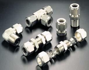
4 Technical Information Introduction k-lok Tube Fittings have been designed specifically for the many demanding applications chemical, petroleum, power generating, pulp, paper and various types of manufacturing industries. They provide a highly reliable, leakproof and torque free seal on all tubing connections. k-lok Tube Fittings are commonly used on instrumentation, process and control systems or any other application where a high quality tube fitting is required Construction of k-lok Body Nut Thread Fittings Front Ferrule Back Ferrule Typical Raw Material List Fitting Material Stainless Steel Type Brass Carbon Steel Bar Stock Forging Tubing ASTM A79 ASTM A7 JIS G0 ASTM B Alloy 0 ASTM B5 Alloy 5 JIS H0 Alloy C0 JIS G05 S0C-SC ASTM A F JIS G ASTM B Alloy 77 JIS H0 Alloy C77 JIS G05 S0C-SC ASTM A9 ASTM A ASTM A9 ASTM B ASTM B75 ASTM B IN 7 ASTM A ASTM A79 IN 9 d Alloy 00 ASTM B ASTM B ASTM B5 k-lok Size No. 5 0 / 5/ A B Fractional Tube nd imensions Tube O.. k-lok Thread 5/-0UN -0UN 7/-0UNF -0UNF 9/-0UN -0UNF -0UNF -0UNF --0UN -5/-0UN Hex. Unit:mm A B d Hex k-lok Metric Tube nd imension Unit:mm Size Tube k-lok No. O.. Thread A B d Hex. M mm 5/-0UN M mm -0UN M mm 7/-0UNF M mm -0UNF M 0mm -0UN M mm -0UNF. 5M 5mm -0UNF.9.0 M mm -0UNF.7.0 M mm -0UNF M 0mm --0UN M mm --0UN.0..0 M mm -5/-0UN Standard of Quality for k-lok Fittings The k-lok body, nut, back ferrule and front ferrule are manufactured under very close tolerance control and monitored through Statistic Process Control and are Heat- Code Traceable. The twin ferrule design performs leak proof sealing with all assembly and reassembly motion being transmitted axially through the tubing. This results in no radial movement of the tubing upon assembly and reassembly. Therefore, the tubing is not stressed and the mechanical integrity is maintained. This is the result of close tolerance control in machining, surface smoothness and hardness of each and every part of the k-lok tube fitting. Through this swaging action, the k-lok fitting becomes integrated mechanically with the tubing connected. k-lod fittings are available in Stainless Steel, Brass and Carbon Steel as standard materials, and can be manufactured from various materials upon request. k-lok fittings are tested according to JIS B5 & BS standards. Tubing & Tube Fitting Benefits Tubing has many benefits over piping. Since tubing is able to be bent, this allows lower pressure drop due to fewer connections. This in turn reduces costs because of less fabricating manpower. k-lok connections do not require threading or welding, and are assembled by standard wrench make-up. This results in less assembly and maintenance costs. Tubing Selection For safe, reliable and leak-free seals, tubing should be considered as a fitting component. Quality k-lok fittings provide the best performance when good tubing is used. Care should be taken and general rules followed to have good tubing connections. Copyright 00, Ktech, All Rights Reserved.
5 Tubing - General Rules Tubing Temperature Ratings. For leak-free sealing, the tubing surface is very important. The Tubing must have a good surface free from scratches, draw mark, flat spots or dirt.. In case of welded tubing, it should not have a visible poor bead on its outside diameter.. Using like tubing and fitting material is essential for the same thermal compatibility and corrosion resistance. The tubing material should be compatible with the process fluid, temperature and environment.. Tubing must be softer than fitting material. When tubing and fittings are made of the same material, the metal tubing must be fully annealed. 5. Tubing hardness must be selected according to the information in the table to.. o not select a too thin or thick wall. A too thin wall may collapse and a too thick wall may not properly be deformed by the ferrule action. The wall thickness selection should be based on the applicable pressure, temperature, shock and vibration. 7. Tubing with oval or out-of-roundness appearance may not fit into the fitting. o not force the tubing into the fitting, it may damage the fitting sealing system of the nut, ferrules, or the body. Purchasing the tubing based on the industrial standards such as ASTM or other equivalent specifications doesn't mean that you have the right tubing when we see other variables. See variables below for taking care of your tubing. Material Grade. Weld or Seamless. O.. and Tolerance. Wall thickness and Tolerance 5. Hardness. Ovality (Shape) 7. Concentricity. Surface finish Tube cutting and de-burr both ends Use tube cutter for straight cutting of tubing and clean metal chips from both I.. and O.. of the tube with deburring tool. Hacksaw can be used for cutting improper size by tube cutter and hacksaw blades should have at least teeth per inch. The Maximum and Minimum operating temperatures for various tubing material Tubing Material Stainless Steel Carbon Steel Copper Alloy 00 Alloy C7 Alloy 00 Titanium Teflon Temperature e-rating Factors Temperature Range - F to 00 F (-9 C to 9 C) -5 F to 799 F (-5 C to C) -0 F to 00 F (-0 C to 05 C) - F to 00 F (-9 C to 7 C) -0 F to 000 F (-95 C to 57 C) -05 F to 00 F (-0 C to C) -0 F to 00 F (-95 C to 5 C) -0 F to 50 F (-7 C to 5 C) The allowable working pressure is determined by various temperatures. To determine the working pressure at the specific temperatures, multiply the working pressure at ambient temperature shown in table ~ by the factor shown in table. xample : Tube SS O.. x 0.05 at 700 F. 500psi x 0. = psi. Therefore psi is the maximum allowable working pressure of SS O.. x 0.05 wall tubing. Table. Temperature e-rating Factors Temp. F( C) 00 () 00 (9) 00 (9) 00 (0) 500 (0) 00 () 700 (7) 00 (7) 900 () 000 (5) 00 (9) Stainless Steel ASTM A C. Steel ASTM A Copper ASTM B Alloy Tube bending Bendability is one of tubing benefits against piping, this causes fewer connections therefore fewer leaks potentiality of the system. Proper tube bending practices ensure against potential leaks of hazards. * Bend prior to installing fittings. * Use tube bender, o not bend a tube placed in the fitting. * o not bend close to fitting, allow a certain straight distance from fitting to the starting point of tube bend. For further details, see page 5. Allowable working temperature When lastomer seal is used in the fitting, care must be taken for allowable working temperature. See working temperature below. lastomer seal material NBR (e. g. Perbunan ) FKM (e. g. Viton ) PTF (e. g. Teflon ) Working Temperature -0 C to 0 C (-0 F to 0 F) - C to 0 C (-0 F to 00 F) -0 C to 0 C (-7 F to F)
6 Stainless Steel Tubing Fully annealed 0 or seamless to ASTM A9 or equivalent, suitable for bending and flaring. Hardness : Rb 0 or less Table. For Seamless Stainless Steel Fractional Tubing (Inches) / / 5/ - - Table. For Seamless Stainless Steel Metric Tubing (mm) Tube wall Thickness in Inches ,00,00 9,00,000,500 5,00, ,900 7,000 0,00 5,00,000,00,00 7,500 5,00,00,500,900,00,000 0,00,000,500,700,000,00,00, Working pressures are based on allowable stress value of 0,000PSI (7,00kPa=,7bar) as specified by ASM B.-999 over the temperature range of -9 C to C (-0 F to 00 F). Safety Factor =.75:, considering ultimate tensile strength 75,000PSI (5,700kPa=5,7bar) Pressure calculations are based on maximum O.. and minimum wall thickness and no allowance is made for corrosion and erosion. e.g. ASTM A9 Ox0.05: O tolerance 0.005",W.T. 0%. Calculations are based on 0.505"Ox0.05" W.T. To determine Bar, multiply PSIG by To determine kpa, multiply PSIG by.9, To convert bar to PSIG, multiply bar by.5 For working pressure per ASM B., multiply value by ,00 5,00,00,00,00, ,000,900,00,00,00, ,00,00,00,00,700,000,700,00,000, Working Pressure in Psig,00,900,00,000,500, ,900,00 Tube Wall Thickness in Millimeters Working Pressure in Bar 0 0 0
7 Welded Stainless Steel Tubing Based on ASM B for weld integrity a de-rating factor must be applied to welded tubing. For double butt seam tubing multiply by 0.5 and for single butt seam tubing multiply by 0.0. Copper Tubing Soft annealed seamless to ASTM B75 or equivalent. Hardness : Rb 0 or less Table. For Seamless Copper Fractional Tubing (Inches) / 5/ Tube Wall Thickness in Inches ,700,00,00,00,00,00,00,000 00,00,500,900,00, ,500,700,00,00,00, ,00,00,00,00 900,900,500,00,00 Working Pressure in Psig,00,500,00,500 Table 5. For Seamless Copper Metric Tubing (mm) 0 Tube Wall Thickness in Millimeters Working Pressure in Bar Working pressures are based on allowable stress value of,000psi ( bar=,00kpa) as specified by ASM B.-999 over the temperature range of 9 C to C (-0 F to 00 F). Safety Factor=5:, considering ultimate tensile strength 0,000PSI (07 bar=0,700kpa) Pressure calculations are based on maximum O.. and minimum wall thickness and no allowance is made for corrosion and erosion For working pressure per ASM B., multiply value by 0.9
8 Carbon Steel Tubing Soft annealed seamless to ASTM A79 or equivalent, free from scratches, suitable for bending & flaring. Hardness: Rb7 or less. Table. For Seamless Carbon Steel Fractional Tubing (Inches) / 5/ - - Tube Wall Thickness in Inches Table 7. For Seamless Carbon Steel Metric Tubing (mm) ,000 5,00, ,00,00,700,00,00,00, ,00 7,000 5,500,500,00,00,00,00, ,00 7,00,00,500,500,900,00,00, ,900,00,700,00,700,00, ,00,00,700,00,500,000, ,00,00,700,900,00, ,00,00,00, ,00,000, Working Pressure in Psig,000,00, ,00,700, ,000,00,000 Tube Wall Thickness in Millimeters Working Pressure in Bar Working pressures are based on allowable stress value of 5,700PSI (0 bar=0,00kpa) as specified by ASM B.-999 over the temperature range of -9 C to C (-0 F to 00 F). Safety Factor =.75:, considering ultimate tensile strength 7,000PSI (7 bar=,700kpa). Pressure calculations are based on maximum O.. and minimum wall thickness and no allowance is made for corrosion and erosion. For working pressure per ASM B., multiply value by 0.9 5,00,
9 Alloy 00 Tubing Fully annealed seamless Alloy 00 tubing to ASTM B5 or equivalent. Hardness:Rb75 or less Table. For Seamless Alloy 00 Fractional tubing (Inches) Tube Wall Thickness in Inches ,900,700 0,00,00 7,000 9,00 Working Pressure in Psig,00,00,00,00,00,00,00,000,000,00,00,900,00,900,00 Working pressures are based on allowable stress value of,700psi (,00kPa=bar) as specified by ASM B.-999 over the temperature range of -9 C to C (-0 F to 00 F). Safety Factor =.75:, considering ultimate tensile strength 70,000PSI (,00kPa=,bar) Pressure calculations are based on maximum O.. and minimum wall thickness and no allowance is made for corrosion and erosion. For working pressure per ASM B., multiply value by 0.9 Special Alloy Tubing When Special Alloy Tubing is Selected, we recommend : Fully Annealed Seamless(or Welded and Cold-draw, where permitted) Alloy Tubing to the ASTM specification as shown below. Tubing should be free of scratches for bending or flaring. k-lok material esignator HC IN Ti Tube Material Alloy C7 Alloy 00 Titanium - Grade B B7 B Pressure Rating quivalents : ASTM Number Tubing Type Maximum Hardness Seamless RB 90 Seamless RB 90 Seamless or Welded RB 90 ) bar = 00 kpa =.5 psi ) kpa = 0.0 bar = 0.5 psi ) psi = 0.09 bar =.9 kpa ) kg/cm = 0.9 bar =. psi Tubing for Gas application K-Lok tube fittings are designed for a wide range of leak-free application including gas leak proof and vacuum service. Gases can escape even the most minute leakpath due to their small molecules, Tube must therefore be carefully handled not to get scratched. Use heavier wall tubing for gas service. Heavy wall tubing resists ferrule action by coining out minor defects of the tube surface and thin wall tubes may collapse with little resistance to ferrule action. For Gas service, use the tubing of the un-shadowed section in table 5 -. Cryogenic Service K- Lok Fittings in S Stainless Steel provide highly reliable performance from Cryogenic Temperatures to High Temperature Levels. S Stainless Steel Temperature Rating : - F to 00 F (-9 C to 9 C) Cryogenic Temperature are considered to be Temperatures Below : -00 F (-7 C)

10 Pipe Thread Many k-lok tube fittings have a male or female pipe end. These ends sometimes have a lower pressure rating than the pressure rating of the tube fitting end. Table 9. Pipe nd Pressure Rating Size esignator 0 ISO/NPT Pipe Size / - - Male pisg bar,000 0,000,00 0,000 7,00 7,500 5,00,00 5,00,000 Stainless Steel Brass Carbon Steel Female pisg bar,00,00,500 5,00,00,00,00 5,000,500, Male pisg bar 7,00 5,000,00 5,00,900,700,00,00,500, Female pisg bar,00,00,00,00,00,00,00,500,00, Male pisg bar,000 0,000,00 0,000 7,00 7,500 5,00,00 5,00, Female pisg bar The ratings shown above are based on ASM B.-999 Female pipe ends have lower ratings than male pipe in a given size due to the inner and outer diameters of female threads being larger than those of male pipe ends. The ratings shown above are reference only.,00,00,500 5,00,00,00,00 5,000,500, Pipe Thread Sealant Pipe thread sealant is essential to ensure leak-free seal. Since the Teflon tape is commonly used, we provide information of recommended tape width, as well as the numbers of thread to be wrapped. The Teflon TM tape fills the voids between threads and prevents galling on pipe threads. The sealant usually contains a lubricant. Table 0. Nominal Pipe Size Recommended Tape Width * ASM B.0.-NPT ffective Thread Length (xternal) L* Approx.# of Thread / 7-7-/ Unit : Inches Note:. Wrap Teflon TM Tape clockwise from first thread. o not overhang the first thread, as the tape may get into the fluid system.. Teflon TM tape has a temperature limit of 0 C( 50 F). Note: The information shown in table -0 are not for design purpose, but for reference only. The accuracy of information is not the liability of our company.


11 Ordering Information k-lok tube fittings are ordered by the part number which is constructed as per SA recommended practice.. Tube to Pipe ends xample : MC -N-B k-lok Male Connector. x Male NPT, Brass. MC - N - B k-lok designated as Name of Fittings : See fitting type designator : See tube O.. designator Pipe thread size : See pipe thread designator Pipe thread Symbols : See pipe thread symbol Material : See fitting material designator. Tube to Tube ends xample : U--S k-lok Union material S T - - S. Tee & Cross Tees are described by first the run ( and ) and next the branch ( ). Stepped Shoulder of k-lok Metric Tube Fittings Metric k-lok is obviously different from Fractional with the stepped shoulders machined on Nut and fitting body. Crosses are described by first the run ( and ) and next the branch ( and ). Metric K-Lok Tube Fittings Metric Tube nd Stepped Shoulders Constructed on Nut, Fittings Body
12 Fitting type esignator Identifier escription Identifier escription U Union AF Female Adapter L Union lbow CP Port Connector UR Reducing Union CRP Reducing Port Connector T Union Tee UA AN Union X Union Cross UBA AN Bulkhead Union UB Bulkhead Union AA AN Adapter MCT Thermocouple Connector MCS SA Male Connector MC-N Male Connector LS SA Male lbow MC-R Male Connector LBS 5 SA Male lbow MC-G Male Connector for Bonded Seal TRS SA Male Run Tee OM Male Connector for Metal Gasket TBS SA Male Branch Tee MCB Bulkhead Male Connector COS O-Seal Straight Thread Connector LBM 5 Male lbow COP O-Seal Pipe Thread Connector LM Male lbow CW Male Pipe Weld Connector TRM Male Run Tee LW Male Pipe Weld lbow TBM Male Branch Tee CSW Tube Socket Weld Connector CF Female Connector LSW Tube Socket Weld lbow CG Gauge Connector P Plug CBF Bulkhead Female Connector C Cap LF Female lbow I Tube Insert TRF Female Run Tee N Nut TBF Female Branch Tee FF Front Ferrule R Reducer FB Back Ferrule AB Bulkhead Adapter FS Ferrule Set AM Male Adapter HS-A k-lok Hydraulic Swaging Unit esignator Inch O.. Identifier Metric O.. Identifier / mm M mm M / mm M mm M 5/ 5 mm M 0mm 0M mm M 0 mm M 0mm 0M mm M mm M - 0 mm M - mm M mm M Pipe Thread Size esignator Fitting Material esignator Nom. Size Identifier Material Identifier SS S SSL L SS0 C.Steel C Brass B Alloy00 M Pipe Thread Symbol Type Taper Threads Parallel Threads Symbol R N G U Specification ISO 7/, BS(BSPT), JIS B 00 (PT), IN999 ANSI N.0. (NPT) ISO/, BS 779(BSPP), JIS B00(PF) American Standard Unified Screw Threads


13 Introducing the Z-Series Single Ferrule Technology from k-lok Z-Series Fitting Ordering Using cutting-edge engineering, k-lok has designed and manufactured Z-Series Single Ferrule Fittings to the highest quality standards Leak-Free Z-Series Nuts and Ferrules are designed to use with the k-lok Tube Fitting Body. Features include: Single Ferrule esign Corrosion Resistance Ferrule Fine Molybdenum isulfide (MoS) coated Nut to prevent galling and additional thread lubricant Positive leak-free seal Standard S and Brass Materials Materials, Pressure Ratings, Installation and Tubing Selection. Materials of the k-lok Z-Series Nut and Ferrule, Pressure ratings (when connected with Tubing), Installation and Tubing selections are identical to those of k-lok Tube Fittings. Please refer to a k-lok catalog for additional information FZ-Ferrule Ferrule Part No. FZ- Tube O.. FZ- FZ- FZ- FZ- NZ-Nut Nut Part Tube Hex L No. O.. H inch NZ- 9/ 0.50 NZ- / 0.5 NZ- / 0.9 NZ NZ Identifier escription UZ Union LZ Union lbow URZ Reducing Union TZ Union Tee XZ Union Cross UBZ Bulkhead Union MCZ- N Male Connector MCZ- R Male Connector MCTZ Thermocouple Connector MCZ- G Male Connector for Bonded Seal OMZ Male Connector for Metal Gasket MCBZ Bulkhead Male Connector LBMZ 5 Male lbow LMZ Male lbow TRMZ Male Run Tee TBMZ Male Branch Tee CFZ Female Connector CGZ Gauge Connector CBFZ Bulkhead Female Connector LFZ Female lbow TRFZ Female Run Tee TBFZ Female Branch Tee RZ Reducer ABZ Bulkhead Adapter AMZ Male Adapter AFZ Female Adapter CPZ Port Connector UAZ AN Union UBAZ AN Bulkhead Union AAZ AN Adapter MCSZ SA Male Connector LSZ Positionable SA Male lbow LBSZ Positionable 5 SA Male lbow TRSZ Positionable SA Male Run Tee TBSZ Positionable SA Male Branch Tee COSZ O-Seal Straight Thread Connector COPZ O-Seal Pipe Thread Connector CWZ Male Pipe Weld Connector LWZ Male Pipe Weld lbow CSWZ Tube Socket Weld Connector LSWZ Tube Socket Weld lbow PZ Plug CZ Cap NZ Nut FZ Ferrule All the Assembly imensions are ldentical to those of k-lok fittings. For Additional etails, Please Refer to the imensional Table of each Fitting
14 Union U Union lbow L Tube to Tube Union Reducing Union UR Union Tee T Union Cross X Bulkhead Union UB Male Connector MC-N Male Connector Vent Protector M Bulkhead Male Connector MCB 5 Male lbow LBM Male lbow LM Male Run Tee TRM Tube to Male Pipe MC-R Thermocouple Connector MCT Male Connector for Bonded Seal MC-G Male Connector for Metal Gasket OM Male Branch Tee TBM Tube to Female Pipe Female Connector CF 5, 7 9 0, 7, 9,0,, Gauge Connector CG Bulkhead Female Connector CBF Female lbow LF Female Run Tee TRF Female Branch Tee TBF Reducer R Bulkhead Adapter AB Male Adapter AM Female Adapter AF Port Connector CP AN Union UA AN Adapter AA Stub Tube Connector Reducing Port Connector CRP AN Bulkhead Union UBA Tube to AN Tube 5 SA Male Run Tee TRS 5 7 9,0, Tube to SA O-Ring Seal SA Male Connector MCS Positionable SA Male lbow LS Positionable 5 SA Male lbow LBS Positionable Positionable SA Male Branch Tee TBS O-Seal Straight Thread Connector COS O-Seal Pipe Thread Connector COP Tube to Weld nd Male Pipe Weld Connector CW Male Pipe Weld lbow LW Tube Socket Weld Connector CSW Tube Socket Weld lbow LSW Plug P Cap C Tube Insert I Nut N Front Ferrule FF Back Ferrule FB Ferrule Set FS Gap Gauge IG Swaging Unit HS-A Plug and Cap Spare Parts

15 Union U Connects fractional tube U- U- U- U- U-5 U- U- U-0 U- U- U- U-0 U- U- h H A B in mm in mm in mm / / 5/ / 7/ 7/ 9/ / 5/ -/ -/ / 7/ 9/ / Connects metric tube U-M U-M U-M U-M U-M U-0M U-M U-5M U-M U-M U-0M U-M U-M U-M U-M U-M h H A B L


16 Union lbow L Connects fractional tube L- L- L- L- L-5 L- L- L-0 L- L- L- L-0 L- L- h H A B in mm in mm in mm / / 5/ / / 5/ -/ - - -/ / 7/ 9/ / Connects metric tube L - M L - M L - M L - M L - M L - 0M L - M L - 5M L - M L - M L - 0M L - M L - M L - M L - M L - M h H A B L

17 Reducing Union UR Connects fractional tube h H H A A B B in mm in mm in mm in mm in mm UR - UR - UR - UR - UR - UR - UR 5- UR 5- UR - UR - UR - UR -5 UR - UR - UR - UR 0- UR 0- UR - UR - UR - UR -0 UR - UR - / / 5/ 5/ / / / / / 5/ / 7/ 7/ 9/ 9/ / / / 5/ 5/ -/ -/ -/ -/ / 9/ 9/ 9/ / / / / / 5/ 7/ 5/ 7/ 7/ 9/ 5/ 7/ 9/ 7/ 9/ / / 9/ /
18 Reducing Union UR Connects metric tube h H H A A B B UR M-M UR M-M UR M-M UR M-M UR M-M UR 0M-M UR 0M-M UR M-M UR M-M UR M-0M UR M-0M UR M-M UR M-M UR M-M UR M-0M Connects metric tube to fractional tube UR M- UR M- UR M- UR M- UR M- UR M-5 UR M- UR 0M- UR 0M- UR 0M-5 UR 0M- UR M-5 UR M- UR M- UR 5M- UR M-0 UR M- UR 0M- UR 0M- UR M in 5/ 5/ 5/ mm h H H A A B B

19 Union Tee T Connects fractional tube T- T- T- T- T-5 T- T- T-0 T- T- T- T-0 T- T- h H A B in mm in mm in mm /..7. 7/ /. 5. 9/ / / / / / / / 5/ Connects metric tube T - M T - M T - M T - M T - M T - 0M T - M T - 5M T - M T - M T - 0M T - M T - M T - M T - M T - M h H A B


20 Union Cross X Note : Cross may be made from plate stock Connects fractional tube X- X- X- X- X-5 X- X- X-0 X- X- X- X-0 X- X- h H A B in mm in mm in mm / / 5/ / / 5/ -/ - - -/ / 7/ 9/ / Connects metric tube X-M X-M X-M X-M X-0M X-M X-5M X-M X-M X-0M X-M X-M X-M X-M X-M A B h H

21 Bulkhead Union UB Connects fractional tube UB- UB- UB- UB- UB-5 UB- UB- UB-0 UB- UB- UB- UB-0 UB- UB- Panel h H A B Hole rill size in mm in mm in mm / / 5/ / 9/ / 5/ -/ -/ / 7/ 9/ / Panel Max Thickness Connects metric tube UB - M UB - M UB - M UB - M UB - 0M UB - M UB - 5M UB - M UB - M UB - 0M UB - M UB - M UB - M UB - M h H A B Panel Hole rill size Panel Max Thickness

22 Male Connector MC-N Connects fractional tube to female NPT thread MC -N MC -N MC -N MC -N MC -N MC -N MC -N MC -N MC -N MC -N MC -N MC -N MC -N MC -N MC -N MC -N MC 5-N MC 5-N MC 5-N MC 5-N MC -N MC -N MC -N MC -N MC -N MC -N MC -N MC -N MC -N MC -N MC -N MC 0-N MC 0-N MC 0-N MC -N MC -N MC -N MC -N MC -N MC -N MC -N MC -N MC 0-N MC 0-0N MC 0-N MC -0N MC -N MC -N MC -N MC -0N MC -N MC -N in mm / / / / / 5/ 5/ 5/ 5/ T (NPT) / / / h H A B in mm in mm 5/ 7/ 9/ 7/ 7/ 9/ / 7/ 9/ 9/ / -/ 9/ 9/ / / -/ / / / -/ - 5/ 5/ -/ -/ -/ - -/ / 5/ 5/ 7/ 7/ 7/ 7/ 7/ 9/ 9/ 9/ 9/ 9/ 9/ / / / / /


23 Male Connector MC-R Connects metric tube to female ISO tapered thread MC M - R MC M - R MC M - R MC M - R MC M - R MC M - R MC M - R MC M - R MC M - R MC M - R MC M - R MC M - R MC M - R MC 0M - R MC 0M - R MC 0M - R MC 0M - R MC M - R MC M - R MC M - R MC M - R MC 5M - R MC M - R MC M - R MC M - R MC M - R MC M - R MC M - R MC 0M - R MC 0M - R MC M - R MC M - R MC M - R MC M - R MC M - R MC M - 0R MC M - 0R MC M - R T R(PT) h H A B Thermocouple Connector MCT k-lok thermocouple connector has no shoulder nor sizing angle inside the fitting, the features enable thermocoupler to go through fitting's thread end. Suffix "T" to Male Connector identifier. xample : MCT -N-S for ordering Thermocouple connector O.. " x " NPT S. Assembly Instructions. Position the length of the Thermocouple passed through fitting's thread end and hold it to prevent shifting during assembly.. Turn the nut - after finger tight with a wrench by holding the body with a back up wrench for size " (mm) or above.
 in mm in mm in mm.7. 9/. 7/..7. 9.05 7/..7.. 7/.. 9/. 9/.. 9.05 9/... 9/.. -/.9 9/.. 9.05 / 7. 7.. / 7. 7. -/.9 / 7. 7. / 0.... 0. -/.9. 9.05.9 -/.9 -.5 9.05 5.7-5/. -.5.9 -.9 -.0.5 -.")

24 Male Connector for Bonded Seal MC-G Connects fractional tube to female ISO parallel thread MC -G MC -G MC -G MC -G MC -G MC -G MC -G MC -G MC -G MC -G MC -G MC -G MC -G MC -G MC -G MC -G MC -G MC 0-0G MC -G T h H (PF) in mm in mm in mm.7. 9/. 7/ / /.. 9/. 9/ /... 9/.. -/.9 9/ / / /.9 / / / / / Connects metric tube to female ISO parallel thread MC M-G MC M-G MC M-G MC M-G MC M-G MC M-G MC M-G MC M-G MC M-G MC M-G MC M-G MC M-G MC M-G MC 0M-G MC 0M-G MC 0M-G MC M-G MC M-G MC M-G MC M-G MC M-G MC M-G MC M-G MC M-G MC 0M-G MC 0M-G MC M-G MC M-G MC M-G MC M-G MC M-G MC M-0G MC M-0G MC M-G T G(PF) h H A B L K A B L K

25 ISO Pipe Thread The International Standards Organization created the ISO / and 7/ threads to standardize the nomenclature of several international pipe threads. / The ISO / is a parallel thread that is no sealing threads. The pressure tight seal is usually made metal to metal against the female port or with a gasket. The / is described in following codes.. BS 779 (BSPP). IN-ISO /. JIS B00 (PF). ISO / The / threads sealing available in k-lok ar listed below. A self-centering taper is constructed at the hex. This taper centers a bonded washer to seal to the surface surrounding the female thread. GB Bonded Seal Gasket (Buna N inner ring bonded to carbon steel outer ring) Ordering Number (mm) (in.) (mm) H (in.) (mm) (in.) Sealing by compression against face of body Reference IN 5 Type A GB-- GB-- GB-- GB-- GB-- GB-- GB-0- GB A metal gasket performs the sealing between the reverse bevel of the fitting and the face of the female threaded component. GC Copper Gasket Ordering Number (mm) (in.) (mm) H (in.) (mm) (in.) Sealing by gasket (washer) Reference IN 5 Type B GC-- GC-- GC-- GC-- GC-- GC-- GC-0- GC A gasket is dropped into the flat bottom of the female thread. The face of the male thread exerts a load on the gasket to seal. GG Copper Gasket Ordering Number (mm) (in.) (mm) H (in.) (mm) (in.) GG Sealing by gasket. Reference IN 5 Type Y GG-- GG Gasket Temperature Ratings Gasket Material Ratings GB Buna N -0 C to C (-0 F to 0 F) FKM - C to 0 C (-0 F to 00 F) GC, GG Copper -9 C to 0 C (- F to 00 F)

26 7/ The ISO 7/ is a tapered thread that is sealing threads working by interference fit. This still requires thread sealant for pressure-tight seal by filling the voids between threads further this prevents galling on piping threads. The sealant usually contains a lubricant. The 7/ is described in following codes.. BS (BSPT). JIS B00 (PT). ISO 7/. IN 999 (male thread only) The 7/ looks similar to the NPT thread. See how different they are as illustrated below. ISO 7/ tapered pipe thread NPT tapered pipe threads *55 thread angle *Pitch measured in millimeters *Truncation of root and crest ar round *Taper angle 7 *0 thread angle *Pitch measured in Inches *Truncation of root and crest are flat *Taper angle 7 ISO Internal Parallel Pipe Thread k-lok Pipe Thread esignator ISO Female Parallel Pipe Size Minimum Full Thread epth L Thread Minor iameter 0.7 / / / / / /. Minimum Flat iameter for GB & GC C Male Connector for Metal Gasket OM Connects fractional tube to female ISO parallel thread OM -G OM -G OM -G OM -G OM -G OM -G OM -G OM -G OM -G OM -G OM -G OM -G OM -G OM -G OM -G OM -G OM -G OM 0-0G OM -G T h H (PF) in mm in mm in mm / 9/ -/ -/ / -/ -/ -5/ / 7/ 7/ 9/ 9/ 9/ 9/ / / / A B L K
 - - -....0....0... 5.9 5.9.9.9.9 5..9 5.9 5.9. 5.9 9.")
 H in mm 7.")

27 Male Connector for Metal Gasket OM Connects metric tube to female ISO parallel thread OM M-G OM M-G OM M-G OM M-G OM M-G OM M-G OM M-G OM M-G OM M-G OM M-G OM M-G OM 0M-G OM 0M-G OM 0M-G OM M-G OM M-G OM M-G OM M-G OM 5M-G OM M-G OM M-G OM M-G OM M-G OM 0M-G OM 0M-G OM M-G OM M-G OM M-G OM M-G OM M-G OM M-0G OM M-0G OM M-G T G(PF) h H A B Vent Protector M M-N M-N M-N M-N T (NPT) H in mm 7. 9/ / /.9 Bore-thru pipe plug with Stainless Steel 0x0 mesh, 0.00 diameter wire screen. K-LOK vent protector, known as the mud dauber fittings, protects open ends of instruments, tubing, outlet vents by preventing foreign materials such as insects, debris from entering and clogging systems. Standard S Stainless steel and Brass meterials. L L


28 Bulkhead Male Connector MCB Connects fractional tube to female NPT thread T h h H A L L in mm (NPT) in mm in mm in mm MCB -N MCB -N MCB -N MCB -N MCB -N MCB -N MCB -N MCB -N MCB -N MCB -N MCB 0-0N MCB -N MCB -N / 5/ -/ / 5/ -/ / 9/ 9/ / / / Panel Hole rill size Panel Max Thickness Male lbow LBM Connects fractional tube to female NPT thread LBM -N LBM -N LBM -N LBM -N LBM -N LBM -N LBM -N LBM -N LBM -N T h H A B L L in mm (NPT) in mm in mm / / / / 9/ / / /
 in mm in mm A B L L /.59 /.7 7/. 5/. 0.9 5. 9.05 7.7 /.59.7 7/. 5/. 0.9 5. 9.05 7.7.7. 7/. 5..0.9.90.7. 7/. 5..0.9. /.7.0.7.00.")
29 Male lbow LM Connects fractional tube to female NPT thread LM -N LM -N LM -N LM -N LM -N LM -N LM -N LM -N LM -N LM -N LM -N LM 5-N LM 5-N LM 5-N LM -N LM -N LM -N LM -N LM -N LM -N LM -N LM -N LM -N LM 0-N LM 0-N LM 0-N LM -N LM -N LM -N LM -N LM -N LM 0-0N LM -N LM -N T h H in mm (NPT) in mm in mm A B L L /.59 /.7 7/. 5/ / /. 5/ / / / / /.0 9/ / / / 7. 9/ / 0. 9/ /. 9/ / 9/ / / / / / 7. / / 0. / /.9 / / / / / / / / / / /
 h H 0 0 0 0 0 0............. 7.. 7..9.")
30 Male lbow LM Connects metric tube to female ISO tapered thread LM M - R LM M - R LM M - R LM M - R LM M - R LM M - R LM M - R LM M - R LM M - R LM M - R LM M - R LM M - R LM 0M - R LM 0M - R LM 0M - R LM 0M - R LM M - R LM M - R LM M - R LM M - R LM M - R LM M - R LM M - R LM M - R LM M - R LM M - R LM 0M - R LM 0M - R LM M - R LM M - R LM M - R LM M - R T R(PT) h H A B L L
 H in mm in mm in mm A B L L /.59 /.7 7/. 5/. 0.9 5. 9.05 7.7 /.59.7 7/. 5/. 0.9 5. 9.05 7.7.7. 7/. 5..0.9.90.")
31 Male Run Tee TRM Connects fractional tube to female NPT thread TRM -N TRM -N TRM -N TRM -N TRM -N TRM -N TRM -N TRM -N TRM -N TRM -N TRM -N TRM 5-N TRM 5-N TRM 5-N TRM -N TRM -N TRM -N TRM -N TRM -N TRM -N TRM -N TRM -N TRM 0-N TRM 0-N TRM 0-N TRM -N TRM -N TRM -N TRM -N TRM -N TRM 0-0N TRM -N TRM -N T (NPT) H in mm in mm in mm A B L L /.59 /.7 7/. 5/ / /. 5/ / / / / /.0 9/ / / / 7. 9/ / 0. 9/ /. 9/ / 9/ / / / / 7. / / 0. / /.9 / / / / / / / / / / /
 h H 0 0 0 0 0 0............. 7.. 7..9.7.9 5..9 5.9 5.9. 5.9..7.7.7.7.7. 7.5 0.")
32 Male Run Tee TRM Connects metric tube to female ISO tapered thread TRM M-R TRM M-R TRM M-R TRM M-R TRM M-R TRM M-R TRM M-R TRM M-R TRM M-R TRM M-R TRM M-R TRM M-R TRM 0M-R TRM 0M-R TRM 0M-R TRM 0M-R TRM M-R TRM M-R TRM M-R TRM M-R TRM M-R TRM M-R TRM M-R TRM M-R TRM M-R TRM M-R TRM 0M-R TRM 0M-R TRM M-R TRM M-R TRM M-R TRM M-R T R(PT) h H A B L L
 in mm in mm in mm / / / / 5/ 5/ 5/ - -.59.59.7.7.7.7 5.7 5.7 5.7 9.05 9.")
33 Male Branch Tee TBM Connects fractional tube to female NPT thread TBM -N TBM -N TBM -N TBM -N TBM -N TBM -N TBM -N TBM -N TBM -N TBM -N TBM -N TBM 5-N TBM 5-N TBM 5-N TBM -N TBM -N TBM -N TBM -N TBM -N TBM -N TBM -N TBM -N TBM 0-N TBM 0-N TBM 0-N TBM -N TBM -N TBM -N TBM -N TBM -N TBM 0-0N TBM -N TBM -N T h H A B L L (NPT) in mm in mm in mm / / / / 5/ 5/ 5/ / / / 7/ / / 9/ 9/ / / / -/ / / / -/ 5/ 5/ -/ -/ -/ / / 5/ 7/ 7/ 9/ 9/ 9/ 9/ 9/ / / / /

34 Male Branch Tee TBM Connects metric tube to female ISO tapered thread TBM M - R TBM M - R TBM M - R TBM M - R TBM M - R TBM M - R TBM M - R TBM M - R TBM M - R TBM M - R TBM M - R TBM M - R TBM 0M - R TBM 0M - R TBM 0M - R TBM 0M - R TBM M - R TBM M - R TBM M - R TBM M - R TBM M - R TBM M - R TBM M - R TBM M - R TBM M - R TBM M - R TBM 0M - R TBM 0M - R TBM M - R TBM M - R TBM M - R TBM M - R T R(PT) h H A B L L
 in mm in mm in mm / / / 5/ 5/ - -.59.59.7.7.7 5.7 5.7 5.7 9.05 9.05..75.0 50.0 / - -.7.7...0.... 7. 7. 7. 7. 7. 0. 0. 0. 0. 5.7 5.7..5.5 7.")
35 Female Connector CF Connects fractional tube to male NPT thread CF -N CF -N CF -N CF -N CF -N CF -N CF -N CF -N CF -N CF 5-N CF 5-N CF -N CF -N CF -N CF -N CF -N CF -N CF -N CF -N CF -N CF 0-N CF 0-N CF 0-N CF -N CF -N CF -N CF -N CF -N CF 0-0N CF -N CF -N T h H A B L (NPT) in mm in mm in mm / / / 5/ 5/ / / 9/ 9/ 9/ 9/ -/ 9/ -/ -5/ -/ -/ -5/ 5/ -/ -5/ -/ -5/ -5/ / 5/ 7/ 7/ 9/ 9/ 9/ 9/ / / / / /

36 Female Connector CF Connects metric tube to male ISO tatered thread T R(PT) h H CF M-R. CF M-R. 9 CF M-R. CF M-R. CF M-R. 9 CF M-R. CF M-R. 7 CF M-R. 5 CF M-R. 9 CF M-R. CF M-R. 7 CF 0M-R 0 9 CF 0M-R CF 0M-R 0 9 CF 0M-R CF M-R. CF M-R CF M-R CF M-R 7 CF M-R 5 CF 5M-R CF M-R.7 7 CF 0M-R CF 0M-R CF M-R. 5 CF M-R. CF M-R. 5 CF M-R. A B L


37 Gauge Connector CG Seepage for GG gasket Connects metric tube to ISO parallel thread (gauge) T R(PF) h H CG M-G. 9 CG M-G. 9 CG M-G. CG M-G. 7 CG M-G CG M-G.5 CG M-G CG 0M-G CG 0M-G CG 0M-G CG M-G 5.5 CG M-G.5 CG M-G CG 0M-G CG M-G Connects fractional tube to ISO parallel thread (gauge) CG -G CG -G CG -G CG -G CG 5-G CG 5-G CG -G CG -G CG -G CG -G CG -G CG -G A B L T h H in mm G(PF) in mm in mm A B L. 9/. 9/ / /. 9/ /.9 9/ / / 7. -/ / /. / /.9 / / / Bulkhead Female Connector CBF Connects fractional tube to male NPT thread T h h H in mm (NPT) in mm in mm in mm CBF -N.7. 9/. 7/. CBF -N /. CBF -N /. CBF -N / 7. CBF -N / 7. CBF -N 0. 5/. 5/.. CBF -N 0. -/.9 5/.. CBF -N / CBF -N CBF 0-0N CBF -N CBF -N Connects metric tube to male NPT thread CBF M-M CBF M-M CBF M-M CBF M-M T (NPT) h h H A A L L L L Panel Hole rill Size Panel Hole rill Size.5.5. Panel Max Thickness Panel Max Thickness

 h H 9 9 9 9 7/ 7/ 9/ 9/ 9/ 9/ / / / / - - - - - 5. 5. 5. 5.... 7. 7. 7. 7.......... 5.7 5.7 7. 7. 7. 7.....5.5.75.0.0.7 5. 5. 5. 5....7.7.7.7........90.")
38 Female lbow LF Connects fractional tube to male NPT thread LF -N LF -N LF -N LF -N LF -N LF -N LF -N LF 5-N LF 5-N LF -N LF -N LF -N LF -N LF -N LF -N LF -N LF 0-N LF 0-N LF -N LF -N LF -N LF -N LF -N LF M-N LF M-N LF M-N LF M-N LF M-N LF M-N LF M-N LF 0M-N LF 0M-N LF 0M-N LF 0M-N LF M-N LF M-N LF M-N LF M-N / 5/ 5/ / / / 9/ / / / / / 5/ -/ / Connects metric tube to male NPT thread T h H A B L L (NPT) in mm in mm in mm T (NPT) h H / 7/ 9/ 9/ 9/ 9/ / / / / A B L L
 in mm in mm in mm / 5/ 5/.7.7.7 5.7 5.7 9.05 9.05....0.... 7. 7. 7. 0. 0. 0. 5.7 5.7..5.5 / / / 9/ / / / / / 5/ -/ - - - -/ 7. 7. 0.. 7. 5.7 7. 0. 0. 0...9.9.9.9. 7/ 7/ 9/ 9/ 9/ 9/ / / / / - - - - -.")

39 Female Run Tee TRF Connects fractional tube to male NPT thread TRF -N TRF -N TRF -N TRF -N TRF -N TRF -N TRF -N TRF 5-N TRF 5-N TRF -N TRF -N TRF -N TRF -N TRF -N TRF -N TRF -N TRF 0-N TRF 0-N TRF -N TRF -N TRF -N TRF -N TRF -N T h H A B L L (NPT) in mm in mm in mm / 5/ 5/ / / / 9/ / / / / / 5/ -/ / / 7/ 9/ 9/ 9/ 9/ / / / / Connects metric tube to male NPT thread TRF M-N TRF M-N TRF M-N TRF M-N TRF M-N TRF M-N TRF M-N TRF M-N TRF 0M-N TRF 0M-N TRF 0M-N TRF 0M-N TRF M-N TRF M-N TRF M-N TRF M-N T (NPT) h H A B L L
 in mm in mm in mm / 5/ 5/.7.7.7 5.7 5.7 9.05 9.05....0.... 7. 7. 7. 0. 0. 0. 5.7 5.7..5.5 / / / 9/ / / / / / 5/ -/ - - - -/ 7. 7. 0.. 7. 5.7 7. 0. 0. 0...9.9.9.9. 7/ 7/ 9/ 9/ 9/ 9/ / / / / - - - - -.")

40 Female Branch Tee TBF Connects fractional tube to male NPT thread TBF -N TBF -N TBF -N TBF -N TBF -N TBF -N TBF -N TBF 5-N TBF 5-N TBF -N TBF -N TBF -N TBF -N TBF -N TBF -N TBF -N TBF 0-N TBF 0-N TBF -N TBF -N TBF -N TBF -N TBF -N T h H A B L L (NPT) in mm in mm in mm / 5/ 5/ / / / 9/ / / / / / 5/ -/ / / 7/ 9/ 9/ 9/ 9/ / / / / Connects metric tube to male NPT thread TBF M-N TBF M-N TBF M-N TBF M-N TBF M-N TBF M-N TBF M-N TBF M-N TBF 0M-N TBF 0M-N TBF 0M-N TBF 0M-N TBF M-N TBF M-N TBF M-N TBF M-N T (NPT) h H A B L L


41 Reducer R Connects fractional tube to frational k-lok R - R - R - R - R - R - R - R - R - R - R - R - R - R -5 R - R - R -0 R - R 5- R 5- R - R - R - R -0 R - R - R - R - R -0 R - R - R0- R0- R0- R- R- R-0 R- R- R0- R0- R- port h in mm in mm in mm in mm / / / / 5/ 5/ / / / 5/ / 5/ 7/ 7/ 7/ 7/ 7/ 9/ 7/ 7/ 9/ / / 9/ 9/ / / / / / / / -/ 5/ 5/ -/ -/ -/ / 5/ 7/ 7/ 7/ 7/ 7/ 7/ 9/ 9/ 9/ 9/ 9/ 9/ 9/ 9/ / / / / / H A B L
42 Reducer R Connects metric tube to fractional k-lok port R M- R M- R M- R M- R M- R M- R M-5 R M- R M- R M- R M- R 0M- R 0M- R M- R M- R M- R M- R M- 0 0 in 5/ mm h H A B L Connects metric tube to metric k-lok R M-M R M-M R M-M R M-0M R M-M R M-M R M-M R M-0M R M-M R M-M R M-0M R M-M R 0M-M R 0M-M R 0M-5M R 0M-M R M-M R M-0M R M-M R M-M R M-0M R M-M R M-M R M-M R M-M R M-M R M-0M R M-M R M-M R 0M-M R 0M-M R 0M-M R 0M-M R M-M R M-0M R M-M R M-M R M-0M port h H A B L


43 Bulkhead Adapter AB Bulkhead Adapter Male lbow The bulkhead adapter is useful for panel construction when you need to set a direction. Connects fractional tube to fractional k-lok AB - AB - AB - AB - AB0-0 AB- AB0-0 AB- AB- port h H in mm in mm in mm.7.0 7/ / / / / A Set a direction L L Panel Hole rill Size Panel Max Thickness Male Adapter AM Connects metric k-lok port to female ISO tapered thread T R(PT) h L AM M-R AM M-R AM M-R AM M-R AM 0M-R AM 0M-R AM 0M-R AM M-R AM M-R AM M-R AM M-R AM M-R AM M-R AM M-0R AM M-0R AM M-R
 in mm in mm AM -N.7.57.77 7/. AM -N.7 7..77 9/. AM -N /.7.57.0 7/. AM -N /.7 7..0 9/. AM -N.57.57 7/. AM -N 7..57 9/. AM -N 0..57 / 7.")


44 Male Adapter AM k-lok Adapter eliminates alignment problems Female Pipe Port In the derection shown the female port is required to connect with tubing. Connects fractional k-lok port to female NPT thread T h (NPT) in mm in mm AM -N /. AM -N /. AM -N / /. AM -N / /. AM -N /. AM -N /. AM -N / 7. AM -N.57. AM 5-N 5/.57 7/. AM 5-N 5/ 7. 9/. AM -N /. AM -N /. AM -N / 7. AM -N 7.. AM -N /. AM -N / 7. AM -N AM 0-N / 7. AM 0-N 5.7. AM 0-N /.9 AM -N AM -N /.9 AM -N AM -N /.9 AM -N /.9 AM -N AM 0-0N AM -N AM -N L Male lbow L The male elbow is positioning in the wrong direction. Male Adapter To eliminate the problem, use a male adapter into the female port. Union lbow Male Adapter Connect a union elbow to the adapter by tightening the k-lok port with a wrench while holding the elbow wrench pad in the desired direction.
 in mm / / 5/ 5/ - -.7.7.7.7 5.7 5.7 5.7 9.05 9.05 9.05..75.0 50.0 - -.77.77.0.0.57.57.57.57 7. 7. 7. 7. 9.90 9.90 9.90.9.9.9 7.7 0.")

45 Female Adapter AF Connects fractional k-lok AF -N AF -N AF -N AF -N AF -N AF -N AF -N AF -N AF 5-N AF 5-N AF -N AF -N AF -N AF -N AF -N AF -N AF -N AF 0-N AF 0-N AF 0-N AF -N AF -N AF -N AF -N AF -N AF -N AF 0-0N AF -N AF -N port to male NPT thread T h in mm (NPT) in mm / / 5/ 5/ / 9/ 9/ -/ 9/ 9/ -/ -/ -/ -5/ -/ -5/ - -5/ -5/ L Connects metric k-lok port to male ISO tapered AF M-R AF M-R AF M-R AF M-R AF 0M-R AF 0M-R AF 0M-R AF M-R AF M-R AF M-R AF M-R T R(PT) h L
 over the port connector. Tighten the nut with wrench until sharp rise in torque is felt.")


46 Port Connector CP Installation Instructions... Port Port k-lok port connector facilitates close connection to another port.. Remove the nut and ferrules from k-lok port and set nut only (no ferrules) over the port connector. Tighten the nut with wrench until sharp rise in torque is felt. Insert the other end of port connector into port and tighten nut - turns with wrench. for ", mm only turn from finger tight. Connects two fractional k-lok CP- CP- CP- CP-5 CP- CP- CP- CP- Connects two metric k-lok CP-M CP-M CP-M CP-M CP-0M CP-M CP-5M CP-M CP-M CP-0M CP-M CP-M CP-M CP-M CP-M in mm / / ports ports L L Reducing Port Connector CRP Connects two fractional k-lok CRP - CRP - CRP - CRP - CRP - CRP - CRP - CRP - CRP - ports in mm in mm.7 / L Connects two metric k-lok ports CRP M-M CRP M-M CRP 0M-M CRP 0M-M CRP M-M CRP M-M CRP M-0M CRP M-M CRP M-M CRP M-M CRP M-M CRP M-M L
 in mm in mm / 5/ - -.59.7.7 9.05.75.0 50.0 5/ - -.7.7 9.05.75.0 50.0 5/- 5/- 7/-0 7/-0-0 7/-0 9/- - -/- -5/- -- -- --.")


 in mm in mm rill Size Thickness - -.7 9.05.75.0 50.")

47 AN Union UA Connects fractional tube to AN flared tube UA - UA - UA - UA - UA 5-5 UA - UA - UA - UA - UA - UA 0-0 UA - UA - AN Tube Straight Flare Size Thread h H in mm in mm T(U) in mm in mm / 5/ / /- 5/- 7/-0 7/-0-0 7/-0 9/- - -/- -5/ / 7/ 9/ / / 7/ 7/ 9/ / / A B L AN Bulkhead Union UBA Connects fractional tube to AN flared tube UBA - UBA - UBA - UBA - UBA - UBA - UBA 0-0 UBA - UBA - AN Tube Straight Panel Panel Flare Size Thread h H A L L Hole Max in mm in mm T(U) in mm in mm rill Size Thickness /- 7/-0 9/- - -/- -5/ / -/ / 9/ / AN Adapter AA Connects factional k-lok AA - AA - AA - AA - AA - port to male AN AN Tube Straight Flare Size Thread h H in mm in mm T(U) in mm in mm.7.7 5/- 7/..7 7/-0 9/. 7/. 7/-0 9/. 9/. 9/- / 7. / A

48 SA Fittings k-lok SA Straight O-Ring Seal Fittings are of positionable feature and provide connection tube to straight thread boss. Further this has an advantage of eliminating welding and brazing process when used as bulkhead fitting on thin wall tanks or vessels. These fittings are designed and manufactured to SA standards as below: Male or xternal Fitting nd imensions to SA J5 Straight thread to SA J75 (equivalent to ANSI B, or ISO R7) Female or Internal Straight Thread Boss to SAJ9. See diagram below. U IA R 0.00(0.) 0.05(0.75) Z K K SA Internal Straight Thread Boss Y O Recommended spotface dia This surface shall be square with the thread pitch dia within 0.00(0.0) FIR. When measured at 0 dia S O-Ring position after Installation Lock Nut Back-Up Washer P J THQ Min boss height IA-This dim applies only when tap drill can not pass thru entire boss, O-Ring etails of SA Internal Straight Thread Boss Nom. / 5/ - - Thread Size 5/- - 7/-0-0 9/ /- -/- -5/- --/ J K ( ) a. iameter U shall be concentric with the thread pitch diameter within 0. full indicator reading (FIR)and shall be free from longitudinal and spiral too marks. Annular tool marks up to.5 Micro meters max. shall be permissble. b. This is the Maximum recommended spotface depth to permit sufficient wrench grip for the proper tightening of the fitting of locknut. c. If the face of the boss is on a machined surface, dimensions Y and S need not apply as long as R 0./ 0.75 is maintained to avoid damage to the O-Ring during installaton. d. Tap drill depths given require the use of bottoming taps to produce the specified full thread lengths. Where standard taps are used, the tap drill depths must be increased accordingly. O P d U a ( ) Y c S bc Max Unit:mm Z ( ) O-Ring and straight thread size for SA Fitting Bosses Nominal / 5/ - - Port Size Thread Size 5/- - 7/-0-0 9/ /- -/- -5/ Size No O-Ring I.. Cross Section inch inch Installation Instruction Step. nsure the locknut is fully raised. Step. Lubricate the O-Ring with a light oil or petroleum and turn the fitting into the straight thread boss until the metal washer is in contact with the boss Step. Position the fitting by backing it out (not more than turn counter-clockwise)until the k-lok fitting is oriented Iin the desired direction. Step. With a back up wrench, hold the wrench pad and tighten the locknut until the washer is set against the face of the boss.


49 SA Male Connector MCS Connects fractional tube to SA straight thread boss Straight Thread h H in mm T(u) in mm in mm MCS -U.7 5/-. 7/. 7/. MCS -U 7/-0. 9/. 9/. MCS -U 9/-. / 7. 9/. MCS -U -.. 9/. MCS -0U -. 9/. MCS 5-5U 5/ MCS -U 7/ / 7. MCS -U 9/- 7. / 7. / 7. MCS -U / 7. MCS -0U - 7. / 7. MCS -U 9/- 7. / 0.. MCS -U MCS -0U MCS -U -/ MCS 0-U /. MCS 0-0U MCS -U / MCS -U / MCS -U. -/ MCS -U -/ MCS -U -5/ MCS 0-0U MCS -U MCS -U A B L O-Ring Uniform Size Number Positionable SA Male lbow LS Connects fractional tube to SA straight thread boss LS -U LS 5-5U LS -U LS -U LS -U LS 0-0U LS -U LS -U LS -U 5/ LS 0-0U- LS -U- LS -U Straight Thread h H H in mm T(u) in mm in mm in mm A B L L 7/-0. 9/. 9/ / / / 7. / / 0. / / / / / / / K O-Ring Uniform Size Number
 in mm in mm in mm A B L L K 7/-0. 9/. 9/. 5. 7.7. 9.90.5.5 9/- 7. 5.7 / 7. / 7..7 9.0 0.57.7.9-0. / 0.....00. 9.05 -/- 5.7 -.5 -.5 -.75. 9.7.7 9.7 7.")


50 Positionable 5 SA Male lbow LBS Connects fractional tube to SA straight thread boss LBS -U LBS -U LBS -U LBS -U LBS -U Straight Thread h H H in mm T(u) in mm in mm in mm A B L L K 7/-0. 9/. 9/ / / 7. / / / / O-Ring Uniform Size Number Positionable SA Male Run Tee TRS Connects fractional tube to SA straight thread boss TRS -U TRS -U TRS -U TRS -U TRS -U TRS 0-0U TRS -U TRS -U Straight Thread h H H in mm T(u) in mm in mm in mm A B L L K 7/-0. 9/. 9/ / / 7. / / / / / O-Ring Uniform Size Number Positionable SA Male Branch Tee TBS Connects fractional tube to SA straight thread boss TBS -U TBS -U TBS -U TBS -U TBS -U TBS 0-0U TBS -U TBS -U Straight Thread h H H in mm T(u) in mm in mm in mm A B L L K 7/-0. 9/. 9/ / / 7. / / / / / / O-Ring Unifom Size Number


51 O-Seal Connector k-lok O-ring seal fittings provide leak-tight sealing on both vacuum and high pressure with a smooth & flat surface perpendicular to the threaded port to ensure metal to metal contact. The standard Buna N O-ring is contained in a precision groove to prevent O-ring extrusion at high pressure and for a controlled squeeze in a vacuum service. Raised Port Counterbored Port Recessed Port A Fig. A Fig. B Fig. A C Mounting imensions for O-seal connectors k-lok COS -U COS -U COS -U COS 5-5U COS -U COS -U COS -U COS -U COP - COP - COP - COP - COP - COP - Straight Thread 5/- - 7/-0-0 9/- - -/- -5/ Pipe Thread NPT NPT NPT NPT NPT NPT Inch A mm iameter B Inch mm Inch C mm Inch epth Max. Max. mm Inch mm When installing an O-ring seal fitting:. Hand-tighten it until the squeeze on the O-ring can be felt during the last turn. Snug the fitting lightly with a wrench When connecting & disconnecting the tubing to the O-ring fitting:. Use a back-up wrench on the fitting hex so it does not turn while the nut is being tightened at the tubing connection.. When disconnecting the tubing also use a back-up wrench so the fitting does not turn. For a recessed port, use a thin back-up wrench (")to hold the fitting hex (Fig.). O-Seal Temperature Ratings NBR (e. g. Perbunan ) FKM (e. g. Viton ) PTF (e. g. Telflon ) -0 C to 0 C (-0 F to 0 F) - C to 0 C (-0 F to 00 F) -0 C to 0 C (-7 F to F)
 in mm in mm.7.7 9.05 5/-0-7/-0-0 9/- - -/- -5/-..0. 7. 0. 5.7.5 9/ 5/ - - -. 5.7 9.05...57.0.5 7/ 9/ / - -.")
 in mm in mm COP - N COP - N COP - N COP -")

52 O-Seal Straight Thread Connector COS Connects fractional tube to female straight thread COS - U COS - U / COS - U COS 5-5U 5/ COS - U COS - U COS - U COS - U Straight Thread h H A B L in mm T(u) in mm in mm /-0-7/-0-0 9/- - -/- -5/ / 5/ / 9/ / O-Ring Uniform Size Number O-Seal Pipe Thread Connector COP Connects fractional tube to female NPT thread T h H A B L in mm *(NPT) in mm in mm COP - N COP - N COP - N COP - N COP - N COP - N COP - N / 5/ - -5/ -5/ * ISO Paralled Threads are available upon request / 9/ 9/ / / / O-Ring Uniform Size Number

53

54 Male Pipe Weld Connector CW Connects fractional tube to pipe CW -P CW -P / CW -P CW -P CW 5-P 5/ CW 5-P 5/ CW -P CW -P CW -P CW -P CW -P CW -P CW 0-P CW -P CW -P CW 0-0P - CW -P - CW -P Male Pipe Size P h H in mm Nom. O.. in mm in mm / 7/ 9/ 9/ 9/ / / -/ 5/ -/ / 9/ 9/ / / / A B L Connects metric tube to pipe Male Pipe Size P Nom. O.. h H CW M-P CW M-P CW M-P CW M-P CW M-P CW M-P CW M-P CW 0M-P CW 0M-P CW 0M-P CW M-P CW M-P CW M-P CW M-P CW 5M-P CW M-P CW M-P CW M-0P CW M-P k-lok Welding information A B L k-lok weld ends are constructed to Schedule 0 wall or greater. The first step is to remove the nut and ferrules from the k-lok fitting to protect them from weld heat and cover the threads with a protective device (i.e. another nut or a plug) P to protect the k-lok port threads & sealing surface from weld spatter. Only finger-tighten the protective device so that you can use it many times. The second step is to tack weld at four positions 90 apart to hold the fitting in place to ensure alignment and concentricity of the components, then complete the weld.


55 Male Pipe Weld lbow LW Connects fractional tube to pipe LW -P LW -P LW -P LW -P LW -P Male Pipe Size P h H in mm Nom. O.. in mm in mm / -/ / 9/ / A B L L Tube Socket Weld Connector CSW Connects fractional tubes CSW - CSW - CSW - CSW - CSW - CSW - h H in mm in mm in mm / / -/ / 9/ / A B L Tube Socket Weld lbow LSW Connects fractional tubes LSW - LSW - LSW - LSW- LSW- h H in mm in mm in mm / -/ / / A B L L


56 Plug P for plugging unused fitting port Installation Instructions. Remove the nut and ferrules from the body. With a wrench, turn from the finger-tight position, ( turn for ", /" and mm, mm and mm) Cap C Installation Instructions. Insert the tube end into the Cap. With a wrench, - turns from the finger-tight position, ( turn for ", /" mm and mm) for capping tube end fractional P- P- P- P- P-5 P- P- P-0 P- P- P- P-0 P- P- metric Width P-M P-M P-M P-M P-M P-0M P-M P-5M H in mm in mm /.59 5/.7 7/. /.7 9/. 5/ 5.7 / across flat H 9 P-M P-M P-0M P-M P-M P-M P-M P-M Width across flat H Cap end of fractional tube h H A B L in mm in mm in mm C- C- C- C- C-5 C- C- C-0 C- C- C- C-0 C- C- / / 5/ / 7/ 7/ 9/ / 5/ -/ -/ / 7/ 9/ / Cap end of metric tube C-M C-M C-M C-M C-M C-0M C-M C-5M C-M C-M C-0M C-M C-M C-M C-M C-M h H A B L


57 Tube Insert I for Nylon or Soft Plastic Tubing fractional I - I - I - I 5- I 5- I 5- I - I - I - I - I 0- I 0- I - I -0 I - in mm in mm / /.7 5/.7 5/ /.7 5/ / Installation Instructions The k-lok Tube Insert supports the soft plastic tubing, thus the tubing does not collapse when the ferrules deform it. When you select a size of Tube Insert, check if the tubing O.. and I.. conform to those of the tube insert. metric I M-M I M-M I 0M-M I M-M I M-0M Nut N fractional N- N- N- N- N-5 N- N- N-0 N- N- N- N-0 N- N- H in mm in mm / / 5/ / 7/ 9/ / L metric N - M N - M N - M N - M N - M N - 0M N - M N - 5M N - M N - M N - 0M N - M N - M N - M N - M N - M H L
58 Front Ferrule FF fractional FF- FF- FF- FF- FF-5 FF- FF- FF-0 FF- FF- FF- FF-0 FF- FF- in / / 5/ - - mm metric FF-M FF-M FF-M FF-M FF-M FF-0M FF-M FF-5M FF-M FF-M FF-0M FF-M FF-M FF-M FF-M FF-M Bcak Ferrule FB fractional FB- FB- FB- FB- FB-5 FB- FB- FB-0 FB- FB- FB- FB-0 FB- FB- in / / 5/ - - mm metric FB-M FB-M FB-M FB-M FB-M FB-0M FB-M FB-5M FB-M FB-M FB-0M FB-M FB-M FB-M FB-M FB-M Ferrule Set FS fractional FS- FS- FS- FS- FS-5 FS- FS- FS-0 FS- FS- FS- in / / 5/ mm metric FS-M FS-M FS-M FS-M FS-M FS-0M FS-M FS-5M FS-M FS-M FS-0M FS-M FS-M Gap Gauge for Pull-up Inspection IG k-lok maintains unbelievably tight tolerance on its each and every part. k-lok tube fittings are monitored and gauged throughout process. This assures k-lok consistency and makes k-lok fittings gaugable. This no-go gauge is the useful tool to inspect if the fittings are pulled up - turns from the finger-tight position. When the gauge doesn't fit the gap between the nut and body hex, the fitting is tightened - turns from the finger-tight position. If the gauge fits the gap, the fittings is not fully tightened. Multiple Size Gap Gauge IG Applicable k-lok ", ", ", mm, 0mm, mm
59 HS-A k-lok Hydraulic Swaging Unit Model No. HS-A For over " Stainless steel and Carbon Steel k-lok fittings k-lok offers a unique & versatile Swaging unit that is easy to operate and allows pre-swaging for " to " (mm to mm). It will save you time and money and even storage space. From now on, hand carry only one unit not many. Our k-lok Swaging unit is designed to pre-swage the front & back ferrule onto the tubing prior to final assembly into a fitting with little physical effort other than the manual pull-up. This unit provides consistent make-up and a reliable leak-free seal. Swaging dies are available from " to " (mm to mm). The k-lok Swaging unit consist of a Hydraulic hand pump, Pump hose, swaging head and swaging dies and are contained in the sturdy steel case. Swaging unit Arm Arm Pin Release position Operating position ARM GRIPPR Lock Nut. Swaging Head Pressure Bleed Valve. JS 5. ie Fixing Bolt. Ratchet Wrench HS-A part list, part number and standard Qty No. Part List Swaging Head HS-SH Hydraulic Hand Pump HS-H-0K Hose HS-PS-.M JS consisting of I and JIG See below 5 ie Fixing Bolt HS-B-5M Ratchet Wrench HS-RW 7 Allen Key HS-K-5M Plastic Carrying Case HS-PC 9 ie & Jig Case HS-C 0 Operating Hannal HS-A-manual Qty -. Hose. Hydraulic Hand Pump Vent/Fill Cap ip Stick Bypass Valve. JS 7. Allen Key ie, Jig and recommended tubing wall thickness k-lok Fitting " " " " -" -" ie 0 0 Jig J J0 J J J0 J J ie & Jig Set Part No. JS JS0 JS JS JS0 JS JS Recommended & Max. Wall Thickness S Tubing Carbon Steel Tubing Max. Max. 0.09" 0.05" 0.05" 0.0" 0.0" 0.095" 0.09" 0.0" 0.095" 0.09" 0.0" 0.5" 0." 0." 0.09" 0.05" 0.05" 0.0" 0.05" 0.0" 0.095" 0.0" 0.095" 0.09" 0.0" 0.0" 0.0" 0.0" How to Order Note : For metric ies and Jigs, suffix M to the designated size. e.g. M and JM for mm die & Jig. Please order our Unit No. HS-A and specify the fitting sizes. e.g. HS-A and ", ", -", -", ". Then the die and Jig Set of JS, JS, JS0, JS and JS shall be included in the steel case. Note : The carrying case is designed to contain sets of die and Jig maximum..


60 INSTALLATION INSTRUCTIONS k-lok is supplied finger-tight and ready for immediate use. Therefore fitting disassembly is not necessary for Step. Make sure the nut is finger-tight. Put the tubing into the k-lok tube fitting until the tube end bottoms on the shoulder inside the fitting. Step Tighten the nut - turn with a wrench by holding the fitting body with a back up wrench. Marking the nut at the 9:00 o' clock position may be necessary for counting the number of turns as the mark will stop at the o' clock position after - turns. * Only turn from finger tight is required for sizes ", /", mm and mm. Re-assembly Instructions k-lok connections can be used many times. Prior to re-assembly, ensure the components are clean and free of defects. Step. Insert the tubing with pre-swaged ferrules and a nut into the body until the front ferrule seats firmly in the fitting body. Step. Hand tighten the nut. Then rotate the nut with a wrench to the original - tight position(sharp rise in torque is felt at the original position) and snug slightly with a wrench. Tube handling during installation. o not force the tubing into the fitting when it does not smoothly go in. It may be a deformed oval or have burs at the tubing end.. It is important to use the proper tube cutter and maintain a sharp cutting wheel on it always.
INSTRUMENTATION. Tube Fittings. Catalog Number 01-5 November,
 INSTRUMNTATION Tube Fittings Catalog Number 0-5 November, 009 www.dklok.com Index Union U Tube to Tube Union Thermocouple Connector MCT Tube to Female Pipe Female Connector CF-N 9,40 Union lbow Union Tee
THE PREMIUM QUALITY. Hydraulic Swaging Unit for Pre-Swaging Over 1. Catalog Number 01-5 March, 2009 HYDRAULICSWAGINGUNIT.
 TH PRMIUM QUAITY Catalog Number 0-5 March, 009 HYRAUICSWAGINGUNIT.HS-A Hydraulic Swaging Unit for Pre-Swaging Over www.dklok.com Index Union U Tube to Tube Union Thermocouple Connector MCT Tube to Female
THE PREMIUM QUALITY. Catalog Number 01-5 November,
 TH PRMIUM QUAITY Catalog Number 0-5 November, 009 www.dklok.com Index Union U Tube to Tube Union Thermocouple Connector MCT Tube to Female Pipe Female Connector CF-N 9,40 Union lbow Union Tee T Union Cross
Table Of Contents. Assembly Instructions. Identification of Sync-Lok Tube Fittings. Reducing Port Connector 36. Male Elbow 11
 able Of Contents eneral Information 1 Union Cross 27 Ordering Information 3 Reducer 28 ube Selection Data 5 Bulkhead Reducer 29 Male Connector 7 Male Adapter 31 Male Bore hrough Connector 9 emale Adapter
Gaugeable Tube Fittings and Adapter Fittings
 www.swagelok.com Gaugeable ittings and dapter ittings vailable in tube sizes from / to 2 in. and 2 to 50 mm Consistent gaugeability upon initial make-up asy to disconnect and retighten Wide variety of
Product warranty. Quality Policy. The Goal
 About the Company SEALEXCEL (INDIA) PVT. LTD. is a fast growing manufacturing company in the field of design, development, production and marketing of high quality valves and fittings for international
TUBE FITTINGS INSTRUMENTATION.
 TUBE FITTINGS INSTRUMENTATION www.unilok.com We, Uni-Lok corporation, have distinguished ourselves in the design and manufacturing of a high performance Twin Ferrule Compression Fittings and Instrumentation
TUBE FITTINGS INSTRUMENTATION.
 TUBE FITTINGS INSTRUMENTATION www.unilok.com We, Uni-Lok corporation, have distinguished ourselves in the design and manufacturing of a high performance Twin Ferrule Compression and Instrumentation Valves
An Installer s Pocket Guide for Swagelok Tube Fittings
 www.swagelok.com An Installer s Pocket Guide for Swagelok Fittings 2 CONTENTS Intermixing/Interchanging... 8 Metric Swagelok Fittings... 8 Installation Instructions Safety Precautions... 9 Up to /25 mm
Gaugeable Tube Fittings and Adapter Fittings
 www.swagelok.com Gaugeable Fittings and dapter Fittings vailable in tube sizes from / to 2 and 2 to 50 mm Consistent gaugeability upon initial installation asy to disconnect and retighten Wide variety
Gaugeable Tube Fittings and Adapter Fittings
 www.swagelok.com Gaugeable Fittings and dapter Fittings vailable in tube sizes from / to 2 and 2 to 50 mm Consistent gaugeability upon initial installation asy to disconnect and retighten Wide variety
DOUBLE FERRULE FITTINGS FLUID CONTROLS PRIVATE LIMITED
 DOUBLE FERRULE FITTINGS FLUID CONTROLS PRIVATE LIMITED INTRODUCTION Fluid Controls Double Ferrule Compression Tube Fittings provide leak proof torque free seals at all tubing connections. They eliminate
Fittings, Materials and Tubing Guide. Instrumentation Products
 Fittings, Materials and Tubing Guide Fittings, Materials and Tubing Guide Instrumentation Products ISO onversion Fittings Visual Index ISO Fitting Nomenclature page 122 Typical Fastening s page 123 Forms
Gaugeable Tube Fittings and Adapter Fittings
 Gaugeable Fittings and dapter Fittings www.swagelok.com Gaugeable Fittings and dapter Fittings TUB vailable in tube sizes from / to 2 and 2 to 50 mm Consistent gaugeability upon initial installation asy
 Shinya Nojima President & COO Technology can be found wherever something is flowing The is a leading manufacturer of high-technology products for a wide range of industries. Our corporate policy is to
Swagelok Medium-Pressure, Gaugeable Tube Fit tings and Adapte r Fit tings
 www.swagelok.com Swagelok Medium-Pressure, Gaugeable Fit tings and dapte r Fit tings For Pre s sure s up to 15 0 0 0 psig (1034 ba r) asy installation, no special tools required ssembly by one full turn
Pipe Fittings 1/16 to 1 in. sizes 316 stainless steel, brass, and carbon steel NPT, ISO/BSP, and SAE threads
 www.swagelok.com Pipe Fittings 1/16 to 1 sizes 316 stainless steel, brass, and carbon steel, /SP, and S threads 2 Pipe Fittings Contents Nipples Page 4 dapters, Gaskets Page 6 Reducing ushings, Reducers
ins LET-LOK (IMPERIAL) TUBE FITTINGS Page About Twin Ferrule Compression Fittings 2 Installation Instructions 3
 TUBE FITTINGS Page About Twin Ferrule Compression Fittings 2 Installation Instructions 3") ins bout win Ferrule Compression Fittings 2 nstallation nstructions 3 Conventions mperial Metric Page 4 32 ndex to et-ok mperial Fittings 4-5 -OK (MPR) UB FGS ndex to et-ok Metric Fittings 32-33 mm ndex
ins bout win Ferrule Compression Fittings 2 nstallation nstructions 3 Conventions mperial Metric Page 4 32 ndex to et-ok mperial Fittings 4-5 -OK (MPR) UB FGS ndex to et-ok Metric Fittings 32-33 mm ndex
STAUFF. Klemmringverschraubungen Twin Ferrule Compression Fittings. Local solutions for individual customers worldwide
 STAUFF Klemmringverschraubungen Twin Ferrule Compression Fittings Local solutions for iniviual customers worlwie INDEX UNION SU Union SRU Reucing Union SBHRU Bulkhea Reucing Union SBHU Bulkhea Union CONNECTORS
Forged High Pressure Pipe Fittings
 Forged High Pressure Pipe Fittings Forged High Pressure Pipe Fittings Pressure Class Socket Weld Forged Fittings Products Dimension Specifications Pressure Class Threaded Forged Fittings Products Dimension
Gaugeable Alloy 400 Mechanically Attached Pipe and Tube Fittings
 www.swagelok.com Gaugeable Alloy 400 Mechanically Attached and Fittings For use with MIL-T-16420K 70/30 and 90/10 copper-nickel tubing and pipe Excellent corrosion resistance in chloride-containing environments
Copper-Nickel Alloy for Seawater Piping Systems (CuNi 90/10)
") Offshore OSNA -10 Copper-Nickel Alloy for Seawater Piping Systems (CuNi 90/10) KME Germany GmbH & Co. KG Offshore OSNA -10 [GB] Content KME - The Company 1 The Material 2 Offshore Product Range 3 Pipes
Offshore OSNA -10 Copper-Nickel Alloy for Seawater Piping Systems (CuNi 90/10) KME Germany GmbH & Co. KG Offshore OSNA -10 [GB] Content KME - The Company 1 The Material 2 Offshore Product Range 3 Pipes
3-PIECE TUBE ASSEMBLY
 3-PIECE TUBE ASSEMBY STAINESS STEE HIGH PRESSURE 37 TUBE FITTINGS 1/8 TO 2 MEETS SAE STANDARD J514 If necessary, see SAE Standard J514 for a complete list of dimensions. NPT Tapered Pipe Threads meet the
COMPRESSION TUBE FITTINGS 1/16 THROUGH 2 -INCH, 2 MM THROUGH 50 MM-METRIC
 1/16 HROUGH 2 -INCH, 2 MM HROUGH 50 MM-MERIC LE-LOK UBE FIINGS ESCRIPION he HM-LE GROUP has produced high quality tube and pipe fittings in various materials for high pressure applications since its establishment
Instrument Pipe & ISO Conversion Fittings. Catalog 4260 Revised, February 1999
 Instrument Pipe & ISO Conversion ittings Catalog 4260 Revised, ebruary 1999 Instrument Pipe ittings Instrument Pipe ittings Introduction Parker Instrumentation Pipe ittings are designed as leakfree connections
Instrument Pipe Fittings Instrument Pipe Fittings Introduction Parker Instrumentation Pipe Fittings are designed as leakfree connections for process,
 Instrument Pipe & ISO Conversion Fittings Catalog 4260 evised, February 1999 Instrument Pipe Fittings Instrument Pipe Fittings Introduction Parker Instrumentation Pipe Fittings are designed as leakfree
Instrumentation Pipe & Weld Fittings. No.03-9 August 2017
 Instrumentation ipe & Weld Fittings No.03-9 August 2017 Instrumentation ipe & Weld Fittings Technical Information Thread Fittings Close Nipple GNC 04 ipe lug G 07 Tee GT 10 ex Nipple GN ex Reducing Nipple
DK-LOK Hydraulic Pipe Fittings
 Class 2000, 3000, 6000, 9000 fittings Catalog No. C-2 June 2012 DK-LOK Hydraulic Pipe Fittings are designed and manufactured to the following standards. ASME B 16.11-2005: Forged fittings, Socket-welding
VCR Metal Gasket Face Seal Fittings
 VR Metal Gasket ace Seal ittings 1/8 to 1 and 6 to 18 mm sizes high-purity stainless steels www.swagelok.com VR Metal Gasket ace Seal ittings Index General Information Glands ages 4, 5, 6 odies ages 6,
Yl)HAl STrrl (INDIA) Forged High Pressure Pipe Fittings. All ISO 9001:2003/ ISO 14001:2004 / 8S Ol!SAS 18001:2007 / PED Al'PROl'ED 97/23/EC
HAl STrrl (INDIA) Forged High Pressure Pipe Fittings. All ISO 9001:2003/ ISO 14001:2004 / 8S Ol!SAS 18001:2007 / PED Al'PROl'ED 97/23/EC") Forged High Pressure Pipe Fittings Forged High Pressure Pipe Fittings Summary : Summary : Type 1. Elbow, Tee, Cross, Couplin g, Half Coupling, Cap, Plug, Bushing, Union, HEX. Nipple, Swage 2. nipple, Bull
Forged High Pressure Pipe Fittings Forged High Pressure Pipe Fittings Summary : Summary : Type 1. Elbow, Tee, Cross, Couplin g, Half Coupling, Cap, Plug, Bushing, Union, HEX. Nipple, Swage 2. nipple, Bull
Pipe Fittings. 1/16 to 1 in. sizes. 316 stainless steel, brass, and carbon steel. NPT, ISO/BSP, and SAE threads.
 Pipe Fittings 1 www.swagelok.com Pipe Fittings PIP 1/16 to 1 sizes 316 stainless steel, brass, and carbon steel, /SP, and S threads 2 Weld, VCR, VCO, Pipe, and Vacuum Fittings Contents Nipples Page 4 Crosses
COMPRESSION TUBE FITTINGS CONNECTORS
 COMPRESSION UBE FIINGS CONNECORS 1/16 HROUGH 2 2 MM HROUGH 50 MM LE-LOK HO OES I ORK? LE-LOK UBE FIINGS ESCRIPION CONNECORS he LE-LOK tube fitting is a mechanism used both to seal and to grip tubing. he
VCR. Metal Gasket Face Seal Fittings. 1/16 to 1 in. and 6 to 18 mm sizes. High-purity stainless steels
 www.swagelok.com Metal asket ace Seal ittings /6 to and 6 to 8 mm sizes igh-purity stainless steels The original design, the authentic brand 2 Metal asket ace Seal ittings ontents lands Page 4 odies Page
Certificate of Type Approval (RQS)
") Date Issued: 18/OCT/2000 Certificate Number: 00-C15300-X Certificate of Type Approval (RQS) This is to certify that Swagelok Company has met the requirements of ABS Product Type Approval for Swagelok Tube
Date Issued: 18/OCT/2000 Certificate Number: 00-C15300-X Certificate of Type Approval (RQS) This is to certify that Swagelok Company has met the requirements of ABS Product Type Approval for Swagelok Tube
VC & VPC Series Check Valves
 VC & VPC Series Check Valves Up to 10 000psig (689 bar), Steel, and Brass Catalog No. VC-4 July 2015 Design VC and VPC Series Check Valves are designed to prevent reverse flow and keep the fluid in one
Introduction Parker are designed for uni-directional flow control of fluids and gases in industries such as chemical processing, oil and gas productio
 Check Valves (C Series) Catalog 4130-C Revised, July 2004 Introduction Parker are designed for uni-directional flow control of fluids and gases in industries such as chemical processing, oil and gas production
Copper & Copper Nickel. Pipes Fittings Flanges.
 Copper & Copper Nickel Pipes Fittings Flanges BOMYUNG METAL.Co.,Ltd CONTENTS 01 COPPER PIPES COPPER PIPES CHEMICAL COMPOSITION / MECHANICAL PROPERTIES / WELDING INSTRUCTION / PIPE / COIL COPPER FITTINGS
Crosby Series 800 and 900 OMNI-TRIM Pressure Relief Valves. Flow Control
 Crosby s Series 800 adjustable blowdown and Series 900 fixed blowdown OMNI-TRIM full nozzle pressure relief valves have a simplified, single trim design with superior application versatility. Features
Thread and Connector Identification
 How to Use this Section This section is intended as an aid to identifying the most popular threads on hydraulic hose couplings and adaptors, and hydraulic equipment. BSP, Metric, American and Japanese
Check Valves (C Series) Catalog 4130-C Revised, July 2004
 Catalog 4130-C Revised, July 2004") Check Valves (C Series) Catalog 4130-C Revised, July 2004 Introduction Parker C Series Check Valves are designed for uni-directional flow control of fluids and gases in industries such as chemical processing,
Check Valves (C Series) Catalog 4130-C Revised, July 2004 Introduction Parker C Series Check Valves are designed for uni-directional flow control of fluids and gases in industries such as chemical processing,
SCREWED BONNET NEEDLE VALVES
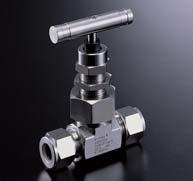
 SCREWED BONNET NEEDLE VALVES H-99 SERIES FEATURES n Blowout-Proof Stem n MAWP* up to 1, psi (69 bar) n MAWT* up to 648 C (12 F) n End connection size range: to 1" or to 25mm n Flow Coefficient (Cv) to1.5
Section 7. Socket Weld and Threaded Fittings. Socket Weld and Threaded Fittings 7-1
 Section 7 Socket Weld and Threaded Fittings This Section contains dimension and tolerance information extracted from American and British specifications applicable to socket weld and threaded fittings.
Multi-Circuit Rotary Block
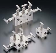
 http://www.pisco.co.jp FITTING CONTROLLER VALVE TUBE MAKE-TO-ORDER PRODUCTS Multi-Circuit Block for Rotating Applications Multi-Circuit Rotary Block 302 Make to Order Suitable for Low-Speed Rotating Applications
Clean Fittings. No.06-2 August 2015
 Clean Fittings No.06-2 ugust 205 Clean Fitting Contents Clean Weld Fittings Mini lbow WM Mini ee WM Mini Cross WMX Mini educing lbow WM Mini educing ee WM Mini educing Union WMU ong lbow W ong ee W ong
Pipe Fittings. HP Series
 Pipe Fittings HP Series Contents Pipe Plug Hollow Hex Plug Close Nipple Special Pipe Nipple Hex Nipple Hex Long Nipple Reducing ushing Pipe Cap Hex Coupling Union all Joints Adaper Male lbow Street lbow
UNITS 1-3 EAGLE WORKS 2 SPRINGCROFT ROAD TYSELEY BIRMINGHAM B11 3EL
 UNITS 1-3 EAGLE WORKS 2 SPRINGCROFT ROAD TYSELEY BIRMINGHAM B11 3EL TEL: 0121 778 6001 FAX: 0121 778 6002 EMAIL: sales@astonfittings.com WEBSITE: www.astonfittings.com QUALITY POLICY The directors of Aston
V33, VP33, VA33, VDA33, VH36 and VL36 Series for VCH36 Series for CNG/NGV applications Pressures up to 3,000 psig (206 bar) and 6,000 psig (413 bar)
 and 6,000 psig (413 bar)") Valves Check Valves V33, VP33, VA33, VDA33, VH36 and VL36 Series for VCH36 Series for CNG/NGV applications Pressures up to 3,000 psig (206 bar) and 6,000 psig (413 bar) No.V336-9 November 2014 Fixed cracking
Valves Check Valves V33, VP33, VA33, VDA33, VH36 and VL36 Series for VCH36 Series for CNG/NGV applications Pressures up to 3,000 psig (206 bar) and 6,000 psig (413 bar) No.V336-9 November 2014 Fixed cracking
Tool Reference Guide. Swagelok Minnesota North Dakota Appleton offers a complete line of tools and equipment to rent or purchase.
 Tool Reference Guide Swagelok Minnesota North Dakota Appleton offers a complete line of tools and equipment to rent or purchase. This allows for ease and accessibility while in the work place. Whether
Tube Fitting Stainless SUS316 Compression Fitting Series
 http://www.pisco.co.jp FITTING CONTROLLER VALVE TUBE MAKE-TO-ORDER PRODUCTS Compression Fitting of Corrosion Resistant Steel Tube Fitting SUS316 Compression Fitting 120 Chemical Industry Medical Industry
COMPRESSION TUBE FITTINGS 1/16 THROUGH 2 2 MM THROUGH 50 MM
 OMPRSSION U IINS 1/16 ROU 2 2 MM ROU 50 MM L-LOK U IINS SRIPION L-LOK O OS I ORK? he L-LOK tube fitting is a mechanism used both to seal and to grip tubing. he mechanical advantage and geometry of this
Copper-Nickel Seawater Piping Systems Offshore product range: Pipes, fittings and flanges of OSNA 10
 Copper-Nickel Seawater Piping Systems Offshore product range: Pipes, fittings and flanges of OSNA 10 KME Germany AG & Co. KG OSNA 10 [GB] Member of the KME Group Contents Your Partner KME The Material
Engineering Data. Assembly Length. How to Determine Correct Assembly Length
 Assembly Length How to Determine Correct Assembly Length For most assemblies, the correct assembly length may be determined by direct measurement of the equipment or a drawing. Minimum bend radii as shown
Hi-Duty Flareless Tube Fittings
 Hi-uty Flareless Tube Fittings dvantages zfc10 No flaring, soldering or other preparation of tubing is necessary. Pre-assembled brass fitting, with sleeve machined onto nut. This two piece flareless compression
Compression Fittings. Brass Compression Fittings. Stainless Steel Compression Fittings. PL Nickel-Plated Brass Spigot Fittings
 Compression Fittings Compression Fittings Stainless Steel Compression Fittings PL Nickel-Plated Spigot Fittings Compression Fittings Compression Fittings Compression Fittings (P. 5-5) Stainless Steel Compression
V33, VP33, VA33, VDA33, VH36 and VL36 Series for VCH36 Series for CNG/NGV applications Pressures up to 3,000 psig (206 bar) and 6,000 psig (413 bar)
 and 6,000 psig (413 bar)") Valves Check Valves V33, VP33, VA33, VDA33, VH36 and VL36 Series for VCH36 Series for CNG/NGV applications Pressures up to 3,000 psig (206 bar) and 6,000 psig (413 bar) No.V336-9 November 2014 Fixed cracking
Valves Check Valves V33, VP33, VA33, VDA33, VH36 and VL36 Series for VCH36 Series for CNG/NGV applications Pressures up to 3,000 psig (206 bar) and 6,000 psig (413 bar) No.V336-9 November 2014 Fixed cracking
INSTRUMENTATION ULTRA HIGH PURITY FITTINGS & VALVES
 INSTRUMENTATION ULTRA HIGH PURITY FITTINGS & VALVES www.unilok.com Since 1984 INSTRUMENTATION Application VB1 series General Ball Valve MWP : 1000psig/69bar with PTFE seats, 2000psig/137bar with TFM seats
* Contact your sales representative for compliance to NACE MR or later requirements.
 VALVES & CONTROLS crosby SERIES 800, 900 OMNI-TRIM, AND BP OMNI-TRIM Crosby s Series 800 adjustable blowdown, Series 900 fixed blowdown OMNI-TRIM, and BP OMNI-TRIM full nozzle pressure relief valves have
FLUID POWER FLUID POWER EQUIPMENT TUTORIAL PIPE WORK. This work covers part of outcome 2 of the Edexcel standard module:
 FLUID POWER FLUID POWER EQUIPMENT TUTORIAL PIPE WORK This work covers part of outcome 2 of the Edexcel standard module: UNIT 21746P APPLIED PNEUMATICS AND HYDRAULICS The material needed for outcome 2 is
Compression Style Transportation
 Compression Style Transportation Air Brake Fittings eets.o.t. FVSS 571.106 eets SAE J246 & J1131 Reusable Use with Copper Tubing TA Fittings eets.o.t. FVSS 571.106 eets SAE J246 & J1131 Staked in Tube
SPEED CONTROLLERS WITH QUICK FITTINGS
 SPEED CONTROLLERS WITH QUICK FITTINGS Union Straight Type Fittings for controlling the speed of actuators, such as cylinders. Superior flow rate characteristics and fine tuning adjustments in the low flow
 +91-8048078009 Kanti Enterprises http://www.kantienterprises.in/ We are amongst the leading Manufacturers, Exporters and Suppliers of this impeccable range of Products like Pipes & Tubes, Flanges, Pipe
Exhaust Throttle (Needle) Valve ET
 Valve ET") http://www.pisco.co.jp CONTROLLER VALVE TUBE MAKE-TO-ORDER PRODUCTS Exhaust Throttle (Needle) Valve Exhaust Throttle (Needle) Valve ET 494 Exhaust Throttle (Needle) Valve with Silencer. Directly Connectable
http://www.pisco.co.jp CONTROLLER VALVE TUBE MAKE-TO-ORDER PRODUCTS Exhaust Throttle (Needle) Valve Exhaust Throttle (Needle) Valve ET 494 Exhaust Throttle (Needle) Valve with Silencer. Directly Connectable
Full Traceability. Material Specification. Raw Material Code. Heat Treatment
 All J.B. Smith swages, bull plugs, tubing and casing nipples, and chambers are traceable to the original mill test report. To ensure traceability, all fittings are steel stamped as follows: Material Specification
Connector Series. Multiple Push-In Fitting Type. Desorption of Several Tubes at One Time. Combinable Connectors by Connector Band.
 http://www.pisco.co.jp FITTING CONTROLLER VALVE TUBE MAKE-TO-ORDER PRODUCTS Multiple Push-In Fitting Type Connector 4 Desorption of Several Tubes at One Time. Combinable Connectors by Connector Band. Combinable
SEAMLESS & WELDED PIPE
 SEAMLESS & WELDED PIPE SPECIFICATIONS: LENGTHS: ASTM A312M-08 6.1 METRE/RANDOMS FINISH: WELDED ANNEALED & PICKLED SEAMLESS COLD FINISH/HOT FINISH NB PIPE SIZE SIZE WELDED SEAMLESS APPROX. WGT Inch mm O.D.
Brass Compression Fitting Range
 Compression Fitting Range Fittings Stud Fittings 0105 BSPT Page 5-9 0105 NPT Page 5-9 0101 BSPP/Metric Page 5-10 0101..39 BSPP Page 5-10 0101 Metric Page 5-11 01 BSPP Page 5-11 0109 BSPT Page 5-12 0109
Solution Partner. Leak - Proof Flow & Control. Check & Relief Valves. W e. s u p p o r t. t h e. i n n o v a t i o n s. o f.
 W e. s u p p o r t. t h e i n n o v a t i o n s. o f. c u s t o m e r s eak - Proof Flow & Control The Best Partner for Value Creation Solution Partner Check & Relief Valves Index Check & Relief Valves
Gyrolok Flareless Tube Fittings Tubing Data Charts
 Gyrolok Flareless Tube Fittings Data Charts DESIGN HOKE Gyrolok Flareless Tube Fittings have been carefully designed and manufactured to provide a wide range of outstanding leak-tight application capabilities.
Pneufit Inch Series Push-In Tube Fittings 1/8" to 1/2" Tube Sizes UNF to 1/2" NPT Thread Options
 Section 1 Pneufit Inch Series Push-In Tube Fittings to 1/2" Tube Sizes 10-32 UNF to 1/2" NPT Thread Options Inch Series Product Numbering System..................FIT-1-2 Inch Series Shapes and odes.........................fit-1-3
Metal Gasket Face Seal Fittings
 Metal Gasket ace Seal ittings Series IOK Group IOK GmbH (Headquarter) Sprendlinger andstr. 5, 63069 Offenbach am Main, Germany el.: +49 69 8900 4498 ax: +49 69 8900 4495 IOK, Inc. 3843 North romenade lvd.,
Medium- and High-Pressure Fittings, Tubing, Valves, and Accessories
 Medium- and High- Fittings, Tubing, Valves, and ccessories 1 www.swagelok.com www.swagelok.com Medium- and High- Fittings, Tubing, Valves, and ccessories FK, FKB, IPT, CTB, and Sno-Trik Series Products
Instrument Thread Fittings High Technology Valve & Fitting Series
 igh Technology Valve & Fitting Series ow To Order IN - 8 NR - SS IRN - 8-6N - B INSTRUMNT TRD FITTINGS FITTING TYP PIP TRD SIZ PIP TRD TYP MTRI Pressure Ratings Size Designator 2 4 6 8 2 6 20 24 32 Size
Betabite Fittings. Hardy Spicer, 1/9 Monterey Road, Dandenong South, Victoria, 3175 Toll free Ph:
 Betabite Fittings, 1/9 Monterey Road, Dandenong South, Victoria, 3175 Toll free Ph: 1300 30 673 Disclaimer The information and dimensions listed in these catalogues is correct to the best of our knowledge
Forged steel socket Welding fittings 6 ~ 13. Forged steel threaded fittings 14 ~ 20. Forged steel outlet fittings 21 ~ 23
 Forged steel socket Welding fittings 6 ~ 13 Forged steel threaded fittings 14 ~ 20 Forged steel outlet fittings 21 ~ 23 Standard threads specifications 24 ~ 25 Comparison of astm specifications and similar
PYPLOK System It s the weldless, threadless way to join pipe/tube
 The Tube-Mac PYPLOK System It s the weldless, threadless way to join pipe/tube Leakfree performance, reduced installed cost and minimised downtime The Tube-Mac PYPLOK connecting system is sparkless and
Tube Fitting Stainless SUS316 Series
 http://www.pisco.co.jp FITTING CONTROLLER VALVE TUE MAKE-TO-ORDER PRODUCTS Push-In Fitting Type of Corrosion Resistant Steel Tube Fitting SUS316 108 Copper alloy free material Nongrease Clean-room packaging
Instrumentation Thread Fittings
 www.superlok.com INDEX ICN 4P IRHB 6P IRSE 8P Close Nipple Reducing Hex Bushing Reducing Street Elbow IHC 6P IME 8P Hex Coupling Male Elbow IHN 4P Hex Nipple IHRC 6P IFT 8P Hex Reducing Coupling Female
10 Series Tube Fittings and Tubing
 0 Series ube ittings and ubing 0,000 psi (690 bar) IOK roup IOK mbh (Headquarter) Sprendlinger andstr. 5, 63069 Offenbach am Main, ermany el.: +49 69 900 449 ax: +49 69 900 4495 IOK, Inc. 343 North romenade
Minimal Fitting Series
 http://www.pisco.co.jp FITTING CONTROLLER VALVE TUE MAKE-TO-ORDER PRODUCTS Ultra-Small arb Fitting for Pneumatic Piping Fitting 266 Suitable for Vacuum Piping by a Combination with Vacuum Tube Suitable
Main Block Series. Concentrated Branching Joint for Assembly. Assembling Manifold Blocks for Concentrated Branching
 http://www.pisco.co.jp FITTING CONTROLLER VALVE TUE MAKE-TO-ORDER PRODUCTS Concentrated ranching Joint for Assembly Main lock 310 Assembling Manifold locks for Concentrated ranching Same Flow Rate with
TUBE & PIPE SECTION D
 TUBE & PIPE SECTION pirtekusa.com Page General Technical ata for Tube and Pipe... 2 Flow Rate & Temperature Recommendations... 3 Schedule 40, 80, 160 Pipe ata... 3 Tube ata Standard Sizes... 4 TUBE AN
Swagelok Alternative Fuel Ser vice (AFS) Ball Valves
 Ball Valves") www.swagelok.com Swagelok Alternative Fuel Ser vice (AFS) Ball Valves For High-Pressure, High-Flow Applications Swagelok AFS Ball Valves Working pressures up to 6000 psig (413 bar) Flow coefficients (C
www.swagelok.com Swagelok Alternative Fuel Ser vice (AFS) Ball Valves For High-Pressure, High-Flow Applications Swagelok AFS Ball Valves Working pressures up to 6000 psig (413 bar) Flow coefficients (C
Needle Valves. Catalog 1203/1205 Aug 2012
 Catalog 1203/1205 Aug 2012 Visual Index Click on link for desire page. At present image not available BAX-NVFF-01 FEMALE FEMALE Page 8 BAX-NVAMF-05 MALE FEMALE (ANGLE TYPE) Page 12 BAX-NVMFD-09 MALE -
Semiconductor / High Purity Products FITTINGS TK SCT. Weld Fittings / Metal Seal Fittings. SCT Division
 Semiconductor / High Purity Products K SC IINGS Weld ittings / etal Seal ittings SC ivision K SC SUPR CN CHNOOGY ICRO W IINGS ORG W IINGS C S IINGS 2 Super Clean itting Series W and etal Seal ittings components
Speed Controller High Flow
 http://www.pisco.co.jp CONTROLLER VALVE TUBE MAKE-TO-ORDER PRODUCTS Speed Control Valve for High Speed Cylinder High Flow Speed Control Valve for Actuator. High Flow Type with Same Size as. Suitable for
Flare Fittings. The World Standard. SAE 45 Flare. Inverted Flare. Access Valves
 Flare Fittings SA 45 Flare eets SA Functional Requirements Resists Vibration Resists echanical Pull-out U isted Inverted Flare U isted conomical Steel ut option Access Valves Teflon Seal on Valve core
Medium- and High-Pressure Fittings, Tubing, Valves, and Accessories
 www.swagelok.com Medium- and High- Fittings, Tubing, Valves, and ccessories FK, FKB, IPT, and Sno-Trik Series Products Rated up to 60 000 psig (4134 bar) nd connections up to 1 1/2 and 12 mm NC MR0175/ISO15156
Chlorine Valves and Accessories
 Chlorine Valves and Accessories Chlorine Cylinder & Ton Container Valves Standard Chlorine Institute Design & Alternate Design 1 ALTERNATE VALVE DESIGN vs. STANDARD CHLORINE INSTITUTE VALVE DESIGN FOR
SUPPLY JOINTS CONTENTS
 ACCESSORIES GENERAL CATALOG AIR TREATMENT, AUXILIARY, VACUUM, AND FLUORORESIN PRODUCTS CONTENTS Specifications, Order Codes, Size Table 371 Dimensions 373 NCU Specification Order Codes, Model Table 379
T-Bar Bonnet. Monoflanges STANDARD OPTIONS. O.S.&Y. Bonnet (firesafe) Gas Solution Bonnet. Anti-Tamper Bonnet
 Gas Solution Bonnet. Anti-Tamper Bonnet") T-Bar Bonnet Gas Solution bonnet with non-rotating Metal Stem Tip The Gas Solution bonnet protects the internal and external threads. Moreover, the bonnet thread is less subject to wear, since it is not
T-Bar Bonnet Gas Solution bonnet with non-rotating Metal Stem Tip The Gas Solution bonnet protects the internal and external threads. Moreover, the bonnet thread is less subject to wear, since it is not
Speed Controller with Uni One-touch Fitting Push-lock type. New-stand male threads for piping that reduces the screw-in time by 1/3. Model.
 Speed Controller with Uni One-touch Fitting Push-lock type Series Elbow Universal Brass New-stand male threads for piping that reduces the screw-in time by 1/3. Gasket Female thread Rc, G NP, NPF Shape
2200 North Main Street Washington, PA PH: FX:
 2200 North Main Street 2200 North Main Street KVAB SERIES MEDICAL VALVES All valves MRI compatible - approved to 3 Tesla. Nominal stroke is 1.5 turns. Full flow at ⅓ turn. Strong, durable body is made
Throttle (Needle) Valve PP Series
 Valve PP Series") http://www.pisco.co.jp CONTROLLER VALVE TUBE MAKE-TO-ORDER PRODUCTS Push-In Fitting Type Flow Control Valve for Clean Environment Throttle (Needle) Valve 466 Copper alloy free material Nongrease Clean-room
http://www.pisco.co.jp CONTROLLER VALVE TUBE MAKE-TO-ORDER PRODUCTS Push-In Fitting Type Flow Control Valve for Clean Environment Throttle (Needle) Valve 466 Copper alloy free material Nongrease Clean-room
Series 105 Simplex Strainer Cast Iron Swing Bolt O-Ring Closure, Flanged Connection Class 125 ANSI Flat Face Flange Rating VENT 'A' FLOW
 Series 105 Simplex Strainer Cast Iron Swing Bolt O-Ring Closure, Flanged Connection Class 125 ANSI Flat Face Flange Rating 1/4" NPT VENT 'A' 1/4" NPT 2 - REQ'D 'D' REQ D FOR BASKET REMOVAL 'B' FLOW 'C'
SECTION 2 SAFETY, TOOLS AND EQUIPMENT, SHOP PRACTICES UNIT 7: TUBING AND PIPING
 SECTION 2 SAFETY, TOOLS AND EQUIPMENT, SHOP PRACTICES UNIT 7: TUBING AND PIPING UNIT OBJECTIVES After studying this unit you should be able to list the different types of tubing used in heating, air conditioning,
Manifold Accessories. Catalog 4190-FP-ACC May 2007
 Manifold Accessories Catalog 4190-FP-ACC May 2007 Contents Page 3 Lapped joint tube adaptors (LJ) Page 4 Flange to compression connectors (FC) Page 5 Kidney flanges to compression connectors (KF) Page
Inline Adapters are Electro Polished to 10 Ra Max. 2 Valves supplied with Metal to Metal Face Seal connections have
 CRYOGENIC RELIEF VALVE (STAINLESS) 1/4" and 1/2" NPT -4 and -8 Metal To Metal Face Seal 1/4" and 1/2" Bi-Lok Dual Ferrule Tube 10-750 Psig (0.69-51.7 Bar) STAINLESSCRV Description The Generant Series Stainless
Push-In Fitting Type Quick Exhaust Valve
 http://www.pisco.co.jp CONTROLLER VALVE TUBE MAKE-TO-ORDER PRODUCTS Push-In Fitting Type Valve Valve 482 Suitable for High-Speed Cylinder. Standard Valve is equipped with Silencer. Re-adjustment of exhaust
Solution Partner. Leak - Proof Flow & Control. Check & Relief Valves. W e. s u p p o r t. t h e. i n n o v a t i o n s. o f.
 W e. s u p p o r t. t h e i n n o v a t i o n s. o f. c u s t o m e r s Leak - Proof Flow & Control The Best Partner for Value Creation Solution Partner Check & Relief Valves 2 Check & Relief Valves Index
M Tube Fitting Design Standards & Codes
 25 M Tube Fitting esign Standards & Codes Make-up 1 1/4 turns advance NUT by 1.25 pitces from finger-tigt position. n 20 TPI, 1.25 pitces travel 1/16 in. (1.5875 mm) make-up distance for Gaugeability M