Copper-Nickel Alloy for Seawater Piping Systems (CuNi 90/10)
|
|
|
- Rose Stevenson
- 5 years ago
- Views:
Transcription
 KME Germany GmbH & Co.")
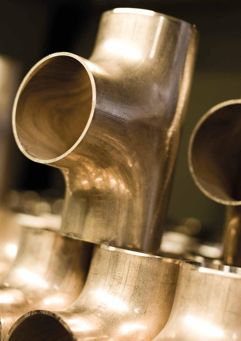
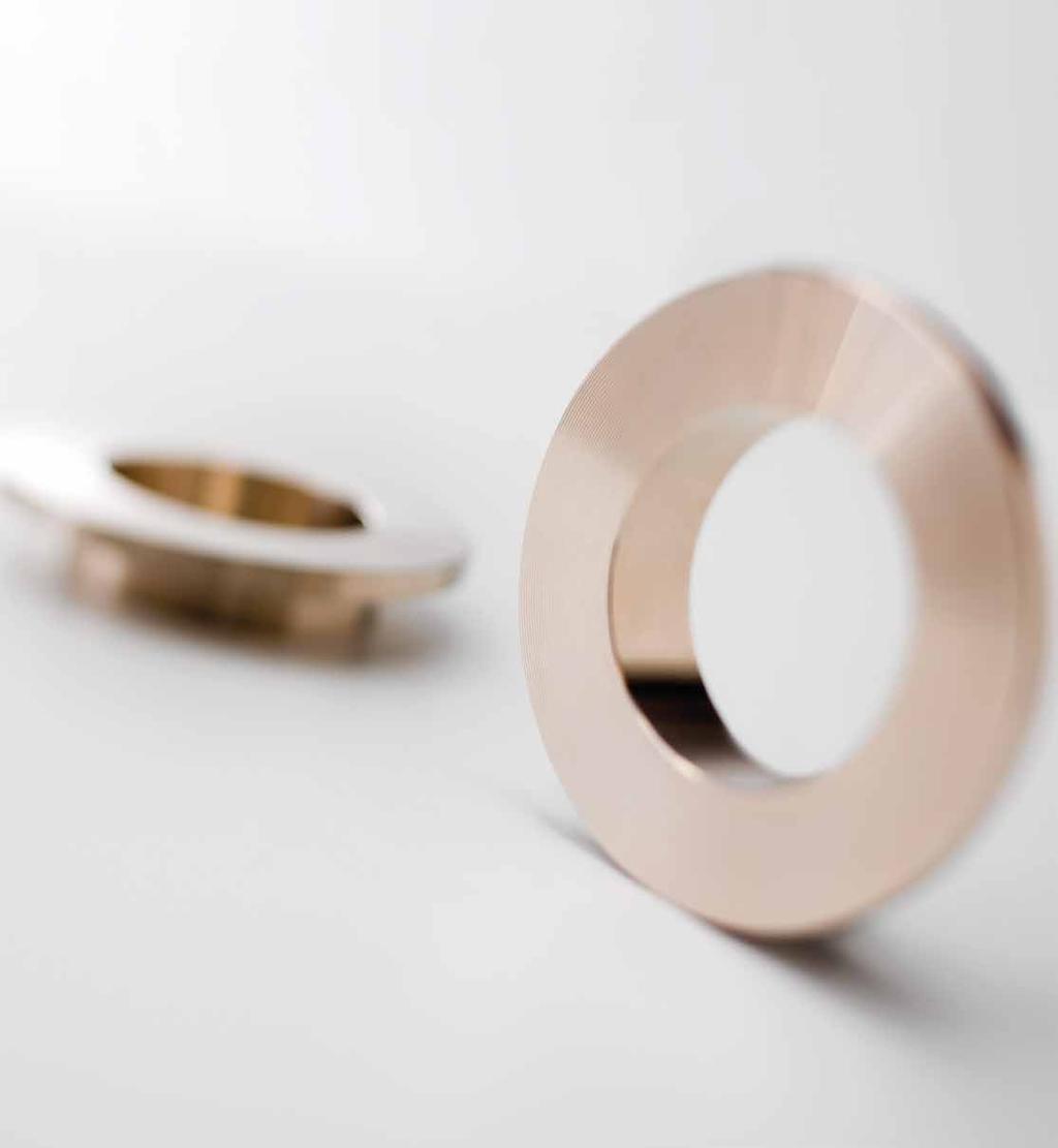
1 Offshore OSNA -10 Copper-Nickel Alloy for Seawater Piping Systems (CuNi 90/10) KME Germany GmbH & Co. KG Offshore OSNA -10 [GB]

2 Content KME - The Company 1 The Material 2 Offshore Product Range 3 Pipes 4 Butt Welding Fittings Elbows 6 Tee Pieces (equal and reduced) 7 Caps 12 Reducers 14 Saddle Pieces 16 Welding Outlets 19 Flanges Composite Weld Neck Flanges 20 Composite Blind Flanges 23 Solid Weld Neck Flanges 24 Solid Slip-On Flanges 26 Composite Slip-On Flanges 27 Capillary Brazing, Socket Weld Fittings and Miscellaneous Elbows 45 / Tees (equal and reducing) 30 Couplings (equal and reducing) 32 (Half-) Couplings 34 Welding Ends 35 Connectors (female and male) 36 Male Unions 38 Unions 39 Hexagon Head/Flush Bushings 40 Sprinkler Bushing 41 Outlets (threaded and socket welding type) 42 End Caps / NPT End Caps 44 Male Nipple (one / both) 45 Female / Male Adpater 46 Hexagon Plug / Round Plug 47 Appendix 48 Design Scope 50 KME Quality Management 53 Yaroslavna Kulinkina,


3 KME - The Company KME as one of the largest manufacturers of copper and copper alloy products offers best possible product and engineering solutions in the various fields of industrial applications. As a leading supplier in the most diverse industries, KME serves the worlds market with a broad spectrum of technologically leading copper and copper-alloy tubes, strips and sheets of outstanding production quality. Marine Applications KME s business unit Marine Applications is specialized in the production of copper-nickel alloys for piping systems in shipbuilding, offshore installations and other marine applications. Since decades, these alloys are successfully used in: Merchant and military shipbuilding Offshore oil and gas installations Coastal petroleum and petrochemical processing plants Seawater desalination plants Coastal electricity generation plants Copper-nickel alloys are widely applied in: Seawater cooling systems Fire water systems Sanitary systems Deck steam pipes Deluge systems Hydraulic and pneumatic systems Seawater feed lines to desalination and processing units Splash zone sheathing 1

4 The Material KME OSNA -10-Alloy The chemical composition of the KME s OSNA -10- alloy is modified to ensure the compliance with all international specifications. Controlled content of alloying elements and minimised concentration of impurities ensure reliable service and fabrication properties of the alloy. Main Advantages of OSNA -10-Alloy Despite the rough conditions in marine service and the highly corrosive nature of seawater, the product range provides a well balanced combination of technical and economical benefits: Straight forward alloying system with good weldability Excellent ductility and toughness Good erosion/corrosion performance Resistant to uniform and localised corrosion No effect of ambient seawater temperatures No effect of seawater chlorination Resistant to biofouling Resistant to stress-corrosion cracking Low maintenance costs Comparison of Standard Specifications for OSNA -10 (CuNi 90/10) KME Alloy OSNA -10 (CuNi 90/10) EN 1652/ 12420/ ) CW352H DIN WL EEMUA 2016, 234/1-2 UNS C 7060 x MIL-T-16420K ASTM B 466 2) /467 C JIS H 3300 C 7060 T Ni % Fe % * Mn % max C % max max max max max Pb % max max max max max max S % max max max max max P % max max max max max Zn % max max max max max max Sn % max other imp. max max max max Cu % rem. rem. rem. rem. min Ni+Fe+Mn min ) formerly BS 2871 Part 2 2) equal to C for subsequent welding * The iron content has been specified to improve corrosion resistance 2

5 Offshore Product Range The OSNA -10 offshore product range is based on: EEMUA 234/1-2, 2016: Tubes 1 Seamless and Welded EEMUA 234/3-6, 2016: Flanges Composite and Solid EEMUA 234/7-13, 2016: Fittings The unique dimensional range from ½ inch to 36 inch ensures the supply of the entire piping systems from one source. Although the pipe dimensions of 38 and 40 inch are not included in the EEMUA they are available here as they are commonly specified in offshore projects. Based on ASME specifications, additional components are included. Furthermore, we are also offering sheets and plates in different sizes. 1 The reference pipe rather than tube is used in this document. 3


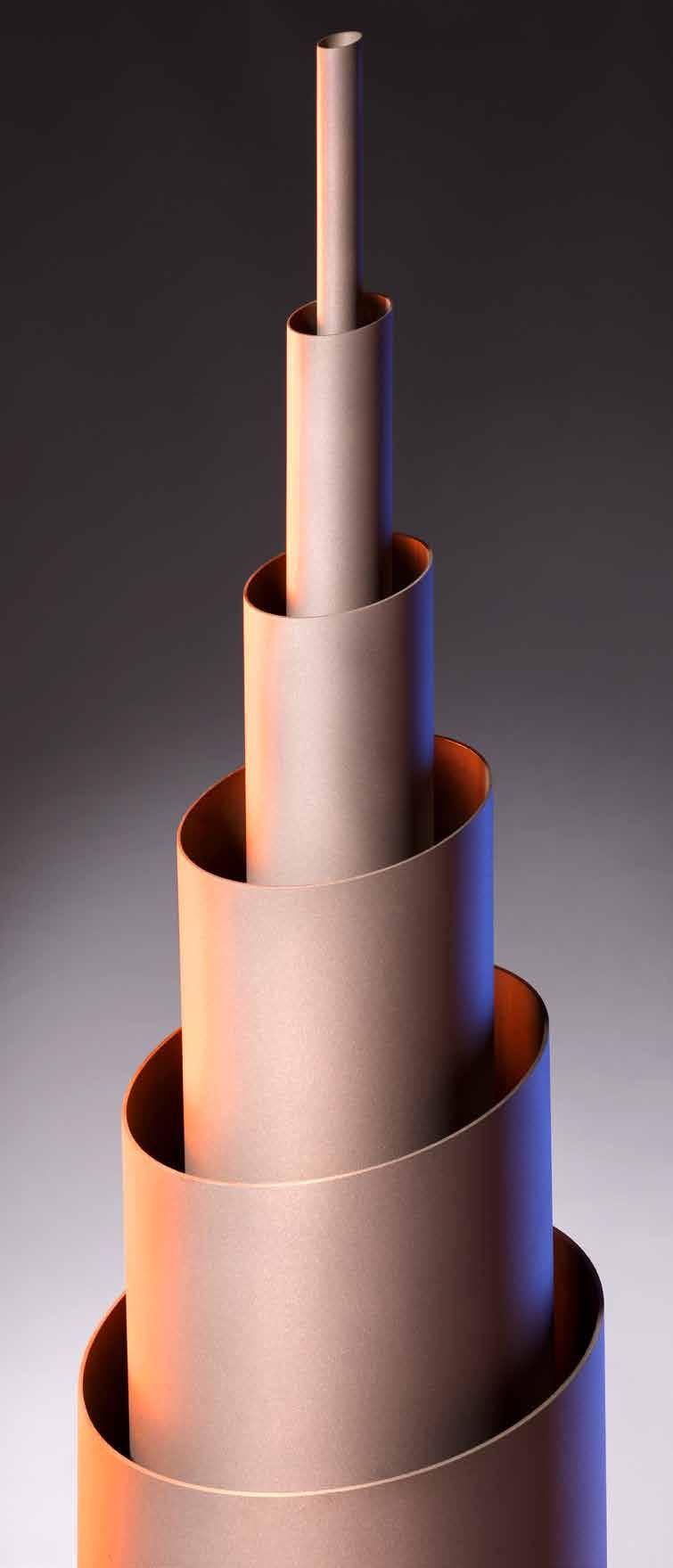
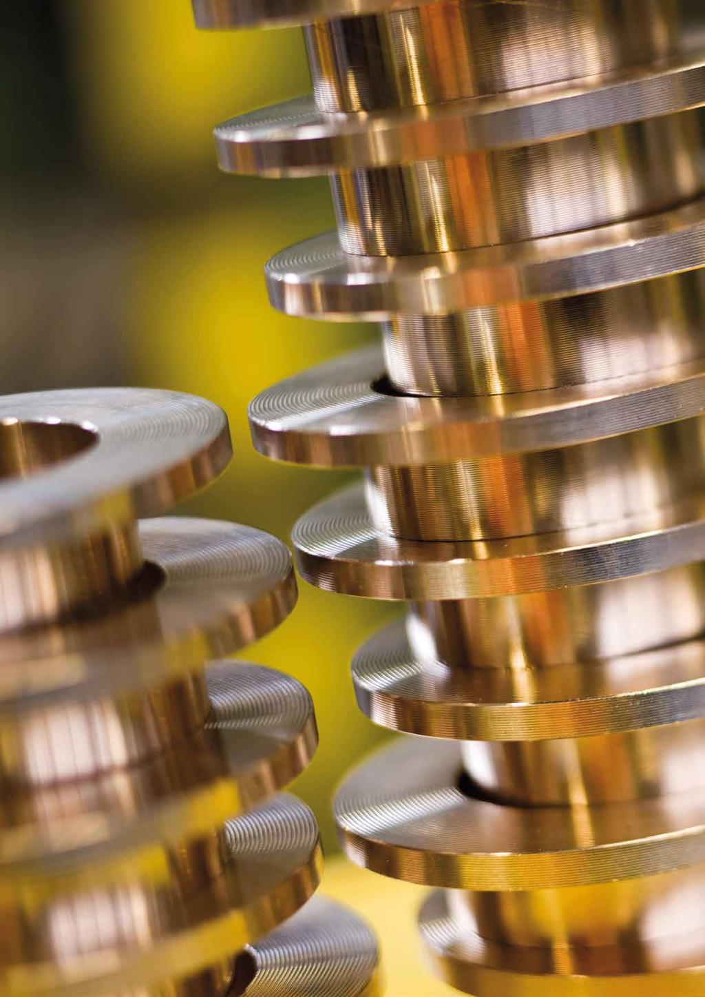
6 Pipes Pipes Seamless Pipes Seamless pipes are in accordance with EEMUA 234/chapter 1. They are manufactured from hot extruded shells followed by cold work and annealing. Welded Pipes Longitudinally welded pipes are in accordance with EEMUA 234/chapter 2. They are manufactured from hot rolled or cold rolled and annealed sheet or plates in accordance with BS 2870, BS 2875, ASTM B171 or ASTM B402. Mechanical testing is carried out in accordance with the standards above. The pipes are supplied in as welded condition. Dimensions Dimensions are based on EEMUA 234, Tables 3/4 and Tables 8/9. However, the pipe diameters range from ½ in./16 mm to 36 in./914 mm. Although the pipe dimensions of 38 in./965 mm and 40 in./1016 mm are not included in the EEMUA they are available on request as they are commonly specified. The corresponding wall thicknesses of the pipes comply with the pressure containment requirements of ASME B31.3 as well as the requirements of the International Association of Classification Societies. Pipes with other wall thicknesses are available on request. Tolerances See notes 1-4 for seamless and notes 2-4 for welded pipes. Weld Preparation For wall thickness less than 3 mm, the pipes are supplied with plain weld ends. Larger thicknesses are supplied with the weld bevel of 37 ½ ±2 ½. 4
7 Pipes Dimensions (mm) Seamless Pipe Size Size Specified Wall Thickness (mm) t Theoretical Weight/Metre (kg) Nominal (in) Specified (mm) 16 bar 20 bar 16 bar 20 bar ½ ¾ ¼ ½ ½ Seam-Welded Pipe Size Size Specified Wall Thickness (mm) t Theoretical Weight/Metre (kg) Nominal (in) Specified (mm) 16 bar 20 bar 16 bar 20 bar Note 1 The pipe sizes up to including 4 in./108 mm are based on BS 2871: Part 2: Table 3 for outside diameters and their tolerances to allow for the use of capillary and compression fittings and brazed (and welded) slip-on flanges. The wall thickness of the 16 bar range have been increased to match the 20 bar range for mechanical strength. Note 2 The pipe size 6 in./159 mm up to 16 in./419 mm are also based on BS 2871: Part 2: Table 3 for specified diameters but the tolerance have been applied to the inside diameters for facilitate alignment of matching weld preparations. Note 3 The ovality of the finished pipe doesn t exceed 2% of the difference of the maximum and minimum diameter measured on the same cross section. Note 4 Up to including 4 in./108 mm, the wall thickness doesn t vary by more than 10 % specified therein. For diameters from 6in./159 mm and larger, the wall thickness is not less than 12.5 % of the specified value. The pipes with other dimensions than mentioned herein are available on request. Please contact us for more information. Stock Dimensions All seamless pipes are available from stock. 5


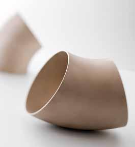
8 Elbows Butt Welding Fittings Type and Construction Elbows are in accordance with EEMUA 234/7. Seamless elbows are typically available up to 18 inch/457 mm. Larger dimensions are manufactured from longitudinally welded half shells. 45 and 90 elbows are available in all sizes. Dimensions Dimensions are based on EEMUA 234/7, Figure 4, Tables and Standard elbows are supplied with long radius, i.e. 1.5 x O.D. Elbows with other dimensions are available on request. Tolerances See Appendix C Weld Preparation For wall thickness less than 3 mm, the elbows are supplied with plain weld ends. Larger thicknesses are supplied with the weld bevel of 37 ½ ±2 ½. Dimensions (mm) Nominal Specified Specified E Approx. Weight (kg) Size Size (OD) Pipe Wall Thickness t in mm 16 bar 20 bar 16 bar 20 bar 16 bar 20 bar ¼ ½ 44.5 Use Use 0.15 Use bar bar bar ½
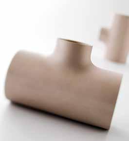
9 Equal Tees Butt Welding Fittings Type and Construction Tee pieces are in accordance with EEMUA 234/7. Seamless tee pieces are typically available up to 8 in./219 mm; bigger dimensions are welded. Dimensions Dimensions are based on EEMUA 234/7, Figures 4-5, Tables and 40. Tee pieces with other dimensions are available on request. Tolerances See Appendix C Weld Preparation For wall thickness less than 3 mm, the tees are supplied with plain weld ends. Larger thicknesses are supplied with the weld bevel of 37 ½ ±2 ½. Dimensions (mm) Nominal Specified Specified Pipe Wall Thickness t Approx. Weight (kg) Size Size (OD) mm in mm 16 bar 20 bar E 16 bar 20 bar ¼ ½ 44.5 Use Use bar bar ½
10 Reducing Tees (16 bar systems) Butt Welding Fittings Type and Construction Pieces are in accordance with EEMUA 234/7. Seamless tee pieces are typically available up to 8 in./219 mm; bigger dimensions are welded. Dimensions Dimensions are based on EEMUA 234/7, Figures 4-5, Tables and Tee pieces with other dimensions are available on request. Tolerances See Appendix C Weld Preparation For wall thickness less than 3 mm, the tees are supplied with plain weld ends. Larger thicknesses are supplied with the weld bevel of 37 ½ ±2 ½. Dimensions for 16 bar systems Specified Size Pipe Wall Thickness Centre-to-End (mm) Approx. E E1 Weight OD mm OD mm OD1 mm t mm t mm t1 mm nom nom kg for sizes from 30 mm up to 108 mm use 20 bar
11 Reducing Tees (16 bar systems) Butt Welding Fittings Dimensions for 16 bar systems Specified Size Pipe Wall Thickness Centre-to-End (mm) Approx. E E1 Weight OD mm OD mm OD1 mm t mm t mm t1 mm nom nom kg for sizes from 30 mm up to 108 mm use 20 bar
12 Reducing Tees (20 bar systems) Butt Welding Fittings Type and Construction Pieces are in accordance with EEMUA 234/7. Seamless tee pieces are typically available up to 8 in./219 mm; bigger dimensions are welded. Dimensions Dimensions are based on EEMUA 234/7, Figures 4-5, Tables and Tee pieces with other dimensions are available on request. Tolerances See Appendix C Weld Preparation For wall thickness less than 3 mm, the tees are supplied with plain weld ends. Larger thicknesses are supplied with the weld bevel of 37 ½ ±2 ½. Dimensions for 20 bar systems Specified Size Pipe Wall Thickness Centre-to-End (mm) Approx. E E1 Weight OD mm OD mm OD1 mm t mm t mm t1 mm nom nom kg

13 Reducing Tees (20 bar systems) Butt Welding Fittings Dimensions for 20 bar systems Specified Size Pipe Wall Thickness Centre-to-End (mm) Approx. E E1 Weight OD mm OD mm OD1 mm t mm t mm t1 mm nom nom kg

14 Caps Butt Welding Fittings Type and Construction End caps are in accordance with EEMUA 234/7, and seamless. Dimensions Dimensions are based on EEMUA 234/7, Figure 4, Tables and 44. The additional wall compensatory thicknesses over and above the minimum pipe wall thicknesses are included. Caps with other dimensions are available on request. Tolerances See Appendix C Weld Preparation For wall thickness less than 3 mm, the caps are supplied with plain weld ends. Larger thicknesses are supplied with the weld bevel of 37 ½ ±2 ½. 16 bar 20 bar Specified t min H t min H Size OD mm mm mm mm Use bar Approx. Weight 16 bar 20 bar kg kg Use bar
15 13
16 Reducers Butt Welding Fittings Type and Construction Eccentric and concentric reducers are in accordance with EEMUA 234/7. The concentric reducers are typically supplied up to incl. 12 in./323.9 mm in seamless condition; bigger dimensions are seamwelded. The eccentric reducers are supplied up to incl. 8 in./219.1 mm in seamless condition; bigger dimensions are seamwelded. Dimensions Dimensions are based on EEMUA 234/7, Figures 4, Tables and Reducers with other dimensions are available on request. Tolerances See Appendix C Weld Preparation For wall thickness less than 3 mm, the reducers are supplied with plain weld ends. Larger thicknesses are supplied with the weld bevel of 37 ½ ±2 ½. Specified Size Length Specified Wall Thickness t x t1 Approx. Weight OD x OD 1 H 16 bar 20 bar 16 bar 20 bar mm mm mm mm kg kg 57 x x x x x x x x x x x x x x x x x x x x x x x x x x x x x x x x x x x x x x x x x x x x x x x x x x x x x x x x x x x x x x x x x x x x x
17 Reducers Butt Welding Fittings Specified Size Length Specified Wall Thickness t x t1 Approx. Weight OD x OD 1 H 16 bar 20 bar 16 bar 20 bar mm mm mm mm kg kg 368 x x x x x x x x x x x x x x x x x x x x x x x x x x x x x x x x x x x x x x x x x x x x x x x x x x x x x x x x x x x x x x x x x x x x x x x x

18 Saddle Pieces Butt Welding Fittings Type and Construction Saddle pieces are in accordance with EEMUA 234/13. Saddle pieces up to including 12 in./ mm are supplied in seamless. Larger dimensions are manufactured from seamless or welded pipes as well as plates. Seamless Dimensions Dimensions are based on EEMUA 234/13, Figures 7-9 and Tables Saddle pieces with other dimensions are available on request. Tolerances The tolerances are based on EEMUA 234/13, Tables Weld Preparation Welding ends of butt weld ends for wall thickness less than 3 mm, the saddle pieces are supplied with plain weld ends. Larger thicknesses are supplied with the weld bevel of 37 ½ ±2 ½. Seamless saddle pieces Header Branch t t Dimension Tolerance on Dimension Tolerance on Specified OD Size Range 16 bar 20 bar L L h h r mm mm mm mm mm mm mm mm mm ± ± All header ± ± sizes equal to ± ± or larger than ± 4 95 ± branch up to ± 4 75 ± and including ± 3 55 ± x 15.5 (16 bar) ± 3 50 ± x 13 (20 bar) ± 3 40 ± ± 3 35 ± ± 3 35 ± Note Other sizes and reducing saddles are available on request. 16
19 Saddle Pieces (16 bar rating) Butt Welding Fittings Type and Construction Saddle pieces are in accordance with EEMUA 234/13. Saddle pieces up to including 12 in./ mm are supplied in seamless. Larger dimensions are manufactured from seamless or welded pipes as well as plates. Seamwelded Dimensions Dimensions are based on EEMUA 234/13, Figures 7-9 and Tables Saddle pieces with other dimensions are available on request. Tolerances The tolerances are based on EEMUA 234/13, Tables Weld Preparation Welding ends of butt weld ends for wall thickness less than 3 mm, the saddle pieces are supplied with plain weld ends. Larger thicknesses are supplied with the weld bevel of 37 ½ ±2 ½. Seamwelded saddle pieces - 16 bar rating Header Branch Dimension Tolerance on Dimension Tolerance on Specified OD Size Range L L h h mm mm mm mm mm mm 914 x ± ± 3.5 All header sizes 813 x ± ± 3.5 equal to or larger than 711 x ± ± 3.5 branch in the range 610 x ± ± x x ± ± 3.0 up to and including x ± ± x x ± ± x ± ± x ± ± x ± ± x ± ±

20 Saddle Pieces (20 bar rating) Butt Welding Fittings Type and Construction Saddle pieces are in accordance with EEMUA 234/13. Saddle pieces up to including 12 in./ mm are supplied in seamless. Larger dimensions are manufactured from seamless or welded pipes as well as plates. Seamwelded Dimensions Dimensions are based on EEMUA 234/13, Figures 7-9 and Tables Saddle pieces with other dimensions are available on request. Tolerances The tolerances are based on EEMUA 234/13, Tables Weld Preparation Welding ends of butt weld ends for wall thickness less than 3 mm, the saddle pieces are supplied with plain weld ends. Larger thicknesses are supplied with the weld bevel of 37 ½ ±2 ½. Seamwelded saddle pieces - 20 bar rating Header Branch Dimension Tolerance on Dimension Tolerance on Specified OD Size Range L L h h mm mm mm mm mm mm All header sizes equal to or larger than branch in the range x 7.0 up to and including 610 x x ± ± x ± ± x ± ± x ± ± x ± ± x ± ± x ± ± x ± ±
.")
21 Welding Outlets Self Reinforced Branch Connector - Butt Welding Type Butt Welding Fittings Type and Construction Welding outlets are in accordance with EEMUA 234/12. The components are manufactured by hot forging and machining from extruded bars (solid or hollow). Dimensions The dimensions and tolerances are suitable for welding to seamless and seam-welded pipes to EEMUA 234/1-2. The branch size covered is from ½ in./ 16 mm to 16 in./419 mm. Other branch sizes are available on request. The welding outlets covered are suitable for application to header sizes from ½ in./16 mm to 38 in./965 mm. The sizes of the header pipes for a given branch size are consolidated in accordance with MSS SP-97, Section 3.3 and Figure 1, whereas the gap distance between the header pipe radius and the fitting inlet radius doesn t exceed 1/16 in./1.6 mm. The design of the self reinforced connection is in accordance with ASME B31.3 Section suitable for both 16 and 20 bar pressure ratings. The additional design feature is the smooth entry into the connection to reduce the turbulences. The overall dimensions are based on EEMUA 234/12, Table 57. section view Branch Header L D K S Specified OD Size Range Nom Nom min/max mm mm mm mm mm mm
22 Composite Weld Neck Flanges Weld Neck Stub Ends and Backing Flanges Flanges Type and Construction The weld neck stub ends are in accordance with EEMUA 234/3 for 16 and 20 bar systems. The range of sizes covered is ½ in./16 mm to 36 in./914 mm. Other sizes are available on request. The stub ends are subdivided in two types short (Type S) based on DIN and long (Type L) based on MSS SP-43 suit the appropriate pipe dimension. The Type L stub ends are included to facilitate the attachments of this type of flange to butt weld welding fittings in accordance with EEMUA 234/7. Dimensions Dimensions are based on EEMUA 234/3, Tables Tolerances The tolerances are based on EEMUA 234/3, Table 15. Weld Preparation The stub ends with S1<3mm are supplied with plain weld ends. Larger dimension are supplied with the weld bevel of 37 ½ ±2 ½. 20


23 Flanges Typ S Typ L 16 bar 20 bar 16 bar 20 bar Nominal Type S Type L S S Size d 3 d 4 d 6 d 7 d 7 H 1 H h 2 h 5 min. min. in mm mm mm mm mm mm mm mm mm mm mm mm ½ ¾ ¼ ½ Use Use bar 20 bar ½

24 Composite Weld Neck Flanges Weld Neck Stub Ends and Backing Flanges Flanges Type and Construction The weld neck backing flanges are in accordance with EEMUA 234/3 and are suitable for both 16 and 20 bar pressure rating. The range of sizes covered is ½ in./16 mm to 36 in./914 mm Class 150. Other sizes are available on request. Drilling and outside diameter dimensions of flange sizes ½ in./16 mm-24 in./610 mm are in accordance with ANSI/ASME B16.5 and BS 1560, whereas the larger sizes, 28 in./711 mm -36 in./914 mm are in accordance with MSS SP-44. The backing flanges are manufactured from forged carbon steel in accordance with ASTM A105N. The chemical composition and mechanical properties of the components are in accordance with EEMUA 234/3, Table 18. The recommended bolting is in accordance with ASTM A193-B7. Unless otherwise specified the flanges are protected by hot dipped galvanising. Dimensions Dimensions are based on EEMUA 234/3, Table 14. Tolerances The tolerances are based on EEMUA 234/3, Table 16. Nominal b Approx. Total Weight Size D min. d 5 K No. of e incl. Stub End kg d 2 in mm mm mm in mm mm mm Bolts mm S 16 bar L S 20 bar L ½ / ¾ / / ¼ / ½ / As for 20 bar / ½ / / / / / / / / / / / / /
25 Composite Blind Flanges Flanges Type and Construction The composite blind flanges are in accordance with manufacturer s specification. The range of sizes covered is ½ in./16 mm to 36 in./914 mm Class 150. Drilling and outside diameter dimensions of flange sizes ½ in./16 mm-24 in./610 mm are in accordance with ANSI/ASME Class 150, whereas the larger sizes, 28 in./711 mm -36 in./914 mm are in accordance with MSS SP-44. The blind flanges are suitable for use both 16 and 20 bar systems. The composite blind flanges are manufactured from forged carbon steel in accordance with ASTM A105N with a welded or bonded C70600 copper nickel disk. In contrast to raised face blind flanges in accordance to ANSI/ASME B16.5, the supplied composite flanges are considered as flat face, since the diameter of the copper nickel disk d1 is equivalent to the flange diameter d4 weld neck stub end in accordance with EEMUA 234/3. By these means, uniform contact over the weld neck stub end faces is ensured. The recommended bolting is in accordance with ASTM A193-B7 and ASTM A194-2H and should be suitably protected from corrosion. Unless otherwise specified the flanges are protected by hot dipped galvanising. Solid blind flanges are available on request. welded glued Tolerances Tolerances are equivalent to the dimensions for weld neck backing flanges based on EEMUA 234/3, Table 16. Nom. Spec. Flange Diameter of Bolt Holes Flange Diameter of No. of Approx. d 2 Size Size Diameter K Thickness Disk Bolt Total Weight in mm D mm mm in mm b min mm d 1 mm Holes (kg) ½ / ¾ / / ¼ / ½ / / ½ / / / / / / / / / / / / /

26 Solid Weld Neck Flanges Flanges Type and Construction The solid weld neck flanges are in accordance with EEMUA 234/5 for 16 and 20 bar systems. The range of sizes covered is ½ in./16 mm to 36 in./914 mm Class 150. Other sizes are available on request. Drilling and outside diameter dimensions of flange sizes ½ in./ 16 mm-24 in./610 mm are in accordance with ANSI/ASME B16.5 and BS 1560, whereas the larger sizes, 28 in./711 mm -36 in./914 mm are in accordance with MSS SP-44. The recommended bolting is in accordance with ASTM B150 alloy UNS C Dimensions Dimensions are based on EEMUA 234/5, Table Tolerances The tolerances are based on EEMUA 234/5, Table bar 20 bar Nominal Outside Thickn. Diameter Hub Dia Length Bore of Bore of Size Diameter of of Hub at weld Through Flange Flange of Flange Flange Chamfer Hub D b d 6 d 3 H d 7 d 7 in mm mm mm mm mm mm mm mm ½ ¾ ¼ Use ½ bar ½ It should be noted that although these flanges are flat faced, inside bolt circle gaskets shall be used and special care should be taken to avoid overtightening the bolting. 24

27 Flanges 16 bar 20 bar 16 bar 20 bar Thickn. Thickn. Approx. Approx. Parallel Diameter Drilling Diameter of Hub at of Hub at Weight Weight Length of Bolt of Bolt Welding Welding of Hub Circle No. of Holes End End Bolts S 1 min S 1 min h K d 2 mm mm kg kg mm mm mm Use 2.5 Use bar bar
28 Solid Slip-On Flanges Flanges Type and Construction The solid slip-on flanges are in accordance with EEMUA 234/6 and are suitable for both 16 and 20 bar systems. The range of sizes covered is ½ in./16 mm to 4 in./108 mm Class 150. Drilling and outside diameter dimensions are in accordance with ANSI/ASME B16.5 and BS The recommended bolting is in accordance with ASTM B150 alloy UNS C Dimensions Dimensions are based on EEMUA 234/6, Table 32. Tolerances The tolerances are based on EEMUA 234/6, Table 33. Nominal Flange Flange No. of Diameter of Approx. Size Diameter Thickness Bolt Holes Bolt Holes Weight D d 3 b H d 6 d 2 K in mm mm mm mm mm mm mm mm kg ½ ¾ ¼ ½ ½
29 Composite Slip-On Flanges Slip-On Stub Ends and Slip-On Backing Flanges Flanges Type and Construction The slip-on stub ends are in accordance with EEMUA 234/4 and are suitable for 16 and 20 pressure rating. The range of sizes covered is ½ in./16 mm to 4 in./108 mm Class 150. The slip-on backing flanges are in accordance with EEMUA 234/4. Drilling and outside diameter dimensions are in accordance with ANSI/ASME B16.5 and BS The backing flanges are suitable for use in both 16 and 20 bar systems. The backing flanges are manufactured from forged carbon steel in accordance with ASTM A105N. The chemical composition and mechanical properties of the components are in accordance with EEMUA 234/4, Table 25. The recommended bolting is in accordance with ASTM A193-B7. Unless otherwise specified the flanges are protected by hot dipped galvanising. Dimensions Dimensions are based on EEMUA 234/4, Tables Tolerances The tolerances are based on EEMUA 234/4, Tables Nominal Inner Stub End Dimension Outer Steel Flange Dimension No. of Bolt Approx. Size d 1 d 3 d 4 H h D b K d 5 d 2 e Holes Total Weight in mm mm mm mm mm mm mm mm mm mm in/mm mm (kg) ½ / 8 / ¾ / 8 / / 8 / ¼ / 8 / ½ / 8 / ¾/ ½ ¾/ ¾/ ¾/
30 Capillary Brazing Elbow 45 Socket Welding Elbow 45 Capillary Brazing, Socket Weld Fittings and Miscellaneous CB SW Elbows mm 57 mm Dimensions Table 45 nominal specified J B D weight min min/max min in mm mm mm mm ~kg ½ ¾ ¼ ½ CB = Capillary Brazing SW = Socket Welding

31 Capillary Brazing Elbow 90 Socket Welding Elbow 90 Capillary Brazing, Socket Weld Fittings and Miscellaneous CB SW Elbows mm 57 mm Dimensions Table 90 nominal specified J D B weight min min min/max in mm mm mm mm ~kg ½ ¾ ¼ ½ CB = Capillary Brazing SW = Socket Welding 29
32 Capillary Brazing Equal Tees Socket Welding Equal Tees Capillary Brazing, Socket Weld Fittings and Miscellaneous CB SW Equal Tees 16 mm 57 mm Dimensions Table Equal Tees nominal specified D B J weight min max/min min in mm mm mm mm ~kg ½ ¾ ¼ ½ CB = Capillary Brazing SW = Socket Welding
33 Capillary Brazing Reducing Tees Socket Welding Reducing Tees Capillary Brazing, Socket Weld Fittings and Miscellaneous CB SW Reducing Tees 16 mm 57 mm Dimensions Table Reducing Tees nominal specified D B J D 1 B 1 J 1 weight min max/min min min max/min min in mm mm mm mm mm mm mm ~kg ¾ x ½ 25 x x ½ 30 x x ¾ 30 x ¼ x ½ 38 x ¼ x ¾ 38 x ¼ x 1 38 x ½ x ½ 44.5 x ½ x ¾ 44.5 x ½ x x ½ x 1¼ 44.5 x x ½ 57 x x ¾ 57 x x 1 57 x x 1¼ 57 x x 1 ½ 57 x CB = Capillary Brazing SW = Socket Welding 31
34 Capillary Brazing Equal Couplings Socket Welding Equal Couplings Capillary Brazing, Socket Weld Fittings and Miscellaneous CB SW Equal Couplings 16mm 57 mm Dimensions Table Equal Couplings nominal specified D B C J L weight min max/min min min min in mm mm mm mm mm mm ~kg ½ ¾ ¼ ½ CB = Capillary Brazing SW = Socket Welding

35 Capillary Brazing Reducing Couplings Socket Welding Reducing Couplings Capillary Brazing, Socket Weld Fittings and Miscellaneous CB SW Reducing Couplings 16 mm 57 mm Dimensions Table Reducing Couplings nominal specified D B J C D 1 B 1 J 1 L weight min max/min min min min max/min min min in mm mm mm mm mm mm mm mm mm ~kg ¾ x ½ 25 x x ½ 30 x x ¾ 30 x ¼ x ½ 38 x ¼ x ¾ 38 x ¼ x 1 38 x ½ x ½ 44.5 x ½ x ¾ 44.5 x ½ x x ½ x 1¼ 44.5 x x ½ 57 x x ¾ 57 x x 1 57 x x 1¼ 57 x x 1 ½ 57 x CB = Capillary Brazing SW = Socket Welding 33
-Couplings / Socket Welding (Half)-Couplings nominal specified D B C J L Halfcoupling Coupling min max/min min min min weight weight in")

36 Capillary Brazing (Half)-Couplings Socket Welding (Half)-Couplings Capillary Brazing, Socket Weld Fittings and Miscellaneous CB SW (Half)-Couplings 16 mm 57 mm Dimensions Table Brazing (Half)-Couplings / Socket Welding (Half)-Couplings nominal specified D B C J L Halfcoupling Coupling min max/min min min min weight weight in mm mm mm mm mm mm ~kg ~kg ½ ¾ ¼ ½ CB = Capillary Brazing SW = Socket Welding
37 35

38 Straight Female Connector Capillary Brazing, Socket Weld Fittings and Miscellaneous CB SW Connector mm 57 mm section view Dimensions Table Female nominal specified d B C L1 J A A/F weight Thread max/min min min min in mm NPT mm mm mm mm mm mm ~kg ½ 16 ½ ¾ 25 ¾ ¼ 38 1¼ ½ ½ CB = Capillary Brazing SW = Socket Welding


39 Straight Male Connector Capillary Brazing, Socket Weld Fittings and Miscellaneous CB SW Connector mm 57 mm section view Dimensions Table Male nominal specified A B C D L J A A/F weight Thread max/min min in mm NPT mm mm mm mm mm mm mm ~kg ½ 16 ½ ¾ 25 ¾ ¼ 38 1¼ ½ ½ CB = Capillary Brazing SW = Socket Welding 37

40 Male Unions Capillary Brazing, Socket Weld Fittings and Miscellaneous Socket Welding Unions, Capillary Brazing Unions, Male Unions, Socket Welding x Male Thread, Capillary Brazing x Male Thread Male Unions 16 mm 57 mm male thread 3/4" - 2" CB SW section view Dimensions Table Male Unions nominal specified d C B D ~L 1 ~L 4 A A/F A/F 1 weight Thread min max/min min min in mm NPT mm mm mm mm mm mm mm mm ~kg ½ 16 x ¾ ¾ ¾ 25 x x 1¼ 1¼ ¼ 38 x 1½ 1½ ½ 44.5 x 1½ 1½ x CB = Capillary Brazing SW = Socket Welding

41 Unions Capillary Brazing, Socket Weld Fittings and Miscellaneous Unions 16 mm 57 mm CB SW section view Dimensions Table Unions nominal specified C B D ~L ~L 3 A/F A/F 1 weight min max/min min in mm mm mm mm mm mm mm mm ~kg ½ ¾ ¼ ½ CB = Capillary Brazing SW = Socket Welding 39


42 Hexagon Head and Flush Bushings Capillary Brazing, Socket Weld Fittings and Miscellaneous Hex. Head and Flush Bushings section view Dimensions Table nominal Thread Thread A H A/F Hex. Head Flush size D d min weight weight in NPT NPT mm mm mm ~kg ~kg ½ ½ ¼ ¾ ¾ ¼ ¾ ¾ 3/ ¼ / ½ ¼ 1¼ ¼ ¼ 1¼ 3/ ¼ 1¼ ½ ¼ 1¼ ¾ ½ 1½ ¼ ½ 1½ 3/ ½ 1½ ½ ½ 1½ ¾ ½ 1½ ¼ / ½ ¾ ¼ ½


43 Sprinkler Bushing Capillary Brazing, Socket Weld Fittings and Miscellaneous Sprinkler Bushing 25 mm 57 mm x 1" - 11/2" NPT section view Dimensions Table nominal specified B A J K d weight max/min min min Thread in mm mm mm mm mm NPT ~kg ¾ ½ ½ ¼ ½ ½ ½ ½ ¾ ¼ ¾ ½ ¾ ¾ ¼ ½ ½ ¼ ¼ ½


44 Threaded Outlets Self Reinforced Branch Connector Threaded Type Capillary Brazing, Socket Weld Fittings and Miscellaneous Threaded Outlets 16 mm 965mm x 1/2" - 2" NPT section view Threaded Outlets Dimensions Table 16/½" - 965/38" x 16/½" - 57/2" - 16/20 bar Nominal Header Size L D K A S Branch Size Ranges Nom Nom Nom min d NPT in mm mm mm mm mm mm ½ ¾ ¼ ½


45 Socket Outlets Self Reinforced Branch Connector Socket Welding Type Capillary Brazing, Socket Weld Fittings and Miscellaneous Socket Outlets 16 mm 57 mm x 16 mm mm section view Socket Outlets Dimensions Table 16/½" - 965/38" x 16/½" - 57/2" - 16/20 bar Branch Header Size L D K J B S Specified OD Ranges Nom max/min Nom Nom min/max min/max mm mm mm mm mm mm mm mm


46 Capillary Brazing End Caps Socket Welding End Caps / NPT End Caps Capillary Brazing, Socket Weld Fittings and Miscellaneous CB SW End Caps 16 mm 57 mm NPT End Caps 16 mm 57 mm section view Dimensions Table nominal specified OD B D L P J A d weight min max/min min min min min min NPT in mm mm mm mm mm mm mm mm ~kg ½ ½ ¾ ¾ ¼ ¼ ½ ½ CB = Capillary Brazing SW = Socket Welding


47 Male Nipple one / Male Nipple both Capillary Brazing, Socket Weld Fittings and Miscellaneous Male Nipple one 1/2" - 2" x 21,3 mm 60,3 mm Male Nipple both 21,3 mm 60,3 mm section view Dimensions Table Male Nipple one nominal B d L A t weight specified Thread min min in mm NPT mm mm mm ~kg ½ 21.3 ½ ¾ 26.7 ¾ ¼ ¼ ½ ½ ½ 21.3 ½ ¾ 26.7 ¾ ¼ ¼ ½ ½ CB = Capillary Brazing SW = Socket Welding 45


48 Female Adapter / Male Adapter Capillary Brazing, Socket Weld Fittings and Miscellaneous Female End Adapter 16 mm 57 mm Male End Adapter 16 mm 57 mm section view Dimensions Table Female Adaptor nominal specified d B D L J A A/F weight Thread max/min min min min min in mm NPT mm mm mm mm mm mm ~kg ½ 16 ½ ¾ 25 ¾ ¼ 38 1¼ ½ ½ Dimensions Table Male Adaptor nominal specified d B D L J A A/F weight Thread max/min min min min min in mm NPT mm mm mm mm mm mm ~kg ½ 16 ½ ¾ 25 ¾ ¼ 38 1¼ ½ ½


49 Hexagon Plug / Round Plug Capillary Brazing, Socket Weld Fittings and Miscellaneous Hex. Plug 21,3 mm 60,3 mm 1/2" - 2" Round Plug 1/2" - 2" section view Dimensions Table nominal size = Length Width of flats Hex height Lenght Dia of Head Hex. Round Thread d A A/F H L D Head Head NPT min min min min min weight weight in mm mm mm mm mm ~kg ~kg ½ ¾ ¼ ½
50 Appendix A Pressure/temperature ratings of flanges Type of Flange Size Range Maximum Allowable Working Pressure-bar 16 bar system 20 bar system 38 C 50 C 75 C 100 C 38 C 50 C 75 C 100 C Composite weld neck (section 1) Composite slip-on (section 2) Solid weld neck (section 3) Solid slip-on (section 4) ½ in/16 mm to 4 in/108 mm 6 in/159 mm to 36 in/914 mm ½ in/16 mm to 4 in/108 mm ½ in/16 mm to 4 in/108 mm 6 in/159 mm to 36 in/914 mm ½ in/16 mm to 4 in/108 mm see 20 bar system see 20 bar system see 20 bar system see 20 bar system Surface finish of the copper-nickel stub end and flangejoint faces Method of machining Ra* µm Rz* µm min. max. min. max. turning Note The term "turning" includes any method of machining producing concentric or spiral grooves. Pressure/temperature ratings - fittings Type of Fitting Size Range Maximum Allowable Working Pressure-bar 16 bar rating 20 bar rating 38 C 50 C 75 C 100 C 38 C 50 C 75 C 100 C Butt welding fittings Socket weld fittings Capillary brazed fittings 1 in/30 mm to 4 in/108 mm 6 in/159 mm to 36 in/914 mm ½ in/16 mm to 2 in/57 mm ½ in/16 mm to 2 in/57 mm use 20 bar use 20 bar Mechanical Properties Tensile Strength 0.2 % Proof Stress Elongation Hardness N/mm 2 PSI N/mm 2 PSI % min HV5 min. max. min. max. on L = 5.65 S 0 max Seamless Pipes Seam-welded pipes * Weld neck and slip-on stub ends, solid weld neck and slip-on flanges * Fittings * * Determined on finished tube outside of heat affected zone 48
51 Appendix B Temperature Range SI Units US Costomary Units 20 C 68 C 100 C 212 C 200 C 392 C 300 C 572 C 400 C 752 F Thermal Expansion Coefficient 10-16/ K 10-16/ K Young s Modulus kn/mm 2 ksi Modulus of Rigidity kn/mm 2 ksi Poisson s Ratio Density g/cm 3 pound/inch Thermal Conductivity W/m K Btu/pound F , Specific Heat Capacitiy kj/kg K BTU/pound F Electrical Conductivity MegaSiemens/cm %IACS Electrical Resistivity microhm-cm circular mil ohm/foot Appendix C Adjust the description of dimensions to the images Size 90 deg & 45 deg elbows & tees (see tables 1.4, 1.6 & 1.7) reducer (see table 1.9) end caps (see table 1.8) Specified OD centre-to-end dimension D,E, C & M overall lenght H up to and including 267 ± 2 ± up to and including 711 ± 3 ± up to and including 914 ± 5 ± 5 overall lenght h1 + h D
52 Design Scope Working pressures and temperatures of components included in this specification: bar/232 psi: -29 C/-20 F to +75 C/+167 F bar/290 psi: -29 C/-20 F to +38 C/+100 F Pipes Seamless and Welded: Pipes are based on BS MA 60, DIN 86007, and ANSI/ASME B31.3 The wall thicknesses comply with ANSI B31.3 and DIN as well as International Association of Classification Societies with additional allowances for robustness to withstand mechanical damage, especially in the smaller sizes. The fit-for-purpose corrosion allowance of 0.5 mm sufficient for entire service life of the piping installation has been included. This corrosion allowance is in accordance with all major classification societies specified for alloys containing 10 wt. % Ni and 1.5 wt. % Fe. Mechanical properties of pipes are given in Appendix A. Flanges Composite and Solid: Included series of composite (lap type) and solid flanges in metric dimensions based on ANSI B16.5, MSS SP-44 and BS 1560 The basic metric dimensions for drilling and flange outside diameters are those given in ANSI B16.5 and MSS SP 44 Class 150 rating with inch size bolting. The copper-nickel stub end and flange joint faces are machine finished and comply with the corresponding Sections of EEMUA 234/3-6 and are summarized in the Appendix A. Mechanical properties pressure/temperature ratings of flanges are given in Appendix A. Fittings: The specification comprises a series for pipe fittings including butt weld, socket welding, capillary brazing, threaded, self-reinforced fittings as well as saddle pieces. The building in dimensions of the butt welding fittings are based on ANSI B16.9 apart from the caps that are based on DIN (with suitable amendments). Mechanical properties pressure/temperature ratings of fittings are given in Appendix A. Physical Properties of CuNi 90/10 The physical properties of the alloy are given by Appendix B. The basic allowable stresses in tension are in accordance with ASME B31.3 Table A-1. Welding The welding consumables used for the manufacturing of welded components are in accordance with AWS-A5.7 Class ER CuNi. The welding procedure specification and welder qualification are in accordance with ASME code, section IX. Testing of Welds The weld seams are examined by the liquid dye penetrant testing in accordance with ASME code, section VIII, division 1, appendix 8. The radiographic examination is performed for the complete length of each weld to meet the requirements of ASME code, section VIII, UW51. Gaskets The gaskets normally used with flanges are those made from aramid fibre with nitrile binder in accordance with ASME B16.21 or equivalent. The gasket hardness shall not be less than 75 Shore. The gaskets shall not be graphited. In order to ensure adequate seating when solid weldneck and solid slip-on flanges are used, irrespective of gasket materials, the gaskets shall be located within the bolt circle. Note: Gaskets should not be used when mating with elastomerlrubber faced flanges. PDMS Data The components mentioned in this catalogue are available in the PDMS-format. Please contact us for more information. 50


53 51
54 52


55 KME Quality-Management KME is committed to the continuous improvement of all our business and production processes in terms of efficiency, effectiveness and reliability as regards their organisation, technological aspects and staff management. The aim of our commitment is to increase the satisfaction of all stakeholders. We are constantly engaged in: creating products of outstanding quality preventing errors and defects minimising the costs associated with errors and inefficiencies preventing the waste of resources establishing safe production conditions to protect both our employees and the environment We aim for excellence by means of transparent management systems designed to satisfy the requirements of our clients together with the demands of the market and technology. The quality management systems implemented throughout the KME Group are fully compliant with the provisions of ISO 9001 as well as, in the case of our automotive industry clients, ISO TS , and our staff is strongly committed to their implementation at all levels. 53
Copper-Nickel Seawater Piping Systems Offshore product range: Pipes, fittings and flanges of OSNA 10
 Copper-Nickel Seawater Piping Systems Offshore product range: Pipes, fittings and flanges of OSNA 10 KME Germany AG & Co. KG OSNA 10 [GB] Member of the KME Group Contents Your Partner KME The Material
Copper-Nickel Alloys for Seawater Piping Systems (CuNi 90/10 and CuNi 70/30)
") Shipbuilding OSNA -10 and OSNA -30 Copper-Nickel Alloys for Seawater Piping Systems (CuNi 90/10 and CuNi 70/30) KME Germany GmbH & Co. KG Shipbuilding - OSNA -10 and OSNA -30 [EN] Content KME - The Company
Shipbuilding OSNA -10 and OSNA -30 Copper-Nickel Alloys for Seawater Piping Systems (CuNi 90/10 and CuNi 70/30) KME Germany GmbH & Co. KG Shipbuilding - OSNA -10 and OSNA -30 [EN] Content KME - The Company
Product Range Shipbuilding
 OSNA -10 and OSNA -30 Product Range Shipbuilding KME Germany AG & Co. KG OSNA -10 and OSNA -30 [GB] Member of the KME Group Contents Range of Applications 1 The Material 2 The Elements 3 Pipes 4 Butt Welding
Copper & Copper Nickel. Pipes Fittings Flanges.
 Copper & Copper Nickel Pipes Fittings Flanges BOMYUNG METAL.Co.,Ltd CONTENTS 01 COPPER PIPES COPPER PIPES CHEMICAL COMPOSITION / MECHANICAL PROPERTIES / WELDING INSTRUCTION / PIPE / COIL COPPER FITTINGS
Section 7. Socket Weld and Threaded Fittings. Socket Weld and Threaded Fittings 7-1
 Section 7 Socket Weld and Threaded Fittings This Section contains dimension and tolerance information extracted from American and British specifications applicable to socket weld and threaded fittings.
Specialising in Cupro Nickel, Copper & Copper Alloys
 Specialising in Cupro Nickel, Copper & Copper Alloys Sunflex Metal Industries Sunflex Metal Industries is a Leading Exporter of Cupro Nickel, Copper, Copper Alloys. 02 World s largest manufacturer and
Hole-cutting. cutting a hole. After the hole has been cut all rough edges must be removed and the area within 5/8 (16mm) of the hole
 of the hole") Mechanical Tees Hole-cutting Shurjoint mechanical tees provide a fast and easy mid-point branch outlet, eliminating the need for welding or the use of multiple fittings. The Model M21 features a female
Mechanical Tees Hole-cutting Shurjoint mechanical tees provide a fast and easy mid-point branch outlet, eliminating the need for welding or the use of multiple fittings. The Model M21 features a female
Yl)HAl STrrl (INDIA) Forged High Pressure Pipe Fittings. All ISO 9001:2003/ ISO 14001:2004 / 8S Ol!SAS 18001:2007 / PED Al'PROl'ED 97/23/EC
HAl STrrl (INDIA) Forged High Pressure Pipe Fittings. All ISO 9001:2003/ ISO 14001:2004 / 8S Ol!SAS 18001:2007 / PED Al'PROl'ED 97/23/EC") Forged High Pressure Pipe Fittings Forged High Pressure Pipe Fittings Summary : Summary : Type 1. Elbow, Tee, Cross, Couplin g, Half Coupling, Cap, Plug, Bushing, Union, HEX. Nipple, Swage 2. nipple, Bull
Forged High Pressure Pipe Fittings Forged High Pressure Pipe Fittings Summary : Summary : Type 1. Elbow, Tee, Cross, Couplin g, Half Coupling, Cap, Plug, Bushing, Union, HEX. Nipple, Swage 2. nipple, Bull
Forged High Pressure Pipe Fittings
 Forged High Pressure Pipe Fittings Forged High Pressure Pipe Fittings Pressure Class Socket Weld Forged Fittings Products Dimension Specifications Pressure Class Threaded Forged Fittings Products Dimension
Forged Steel Fittings CLASS 3000 THREADED
 Forged Steel Fittings CLASS 3000 THREADED NPS 1/8 1/4 3/8 1/2 3/4 1 1 1/4 1 1/2 2 2 1/2 3 4 DN 6 8 10 15 20 25 32 40 50 65 80 100 90 0 ELBOWS A in 0.97* 0.97 1.12 1.31 1.50 1.75 2.00 2.38 2.50 3.25 3.75
DK-LOK Hydraulic Pipe Fittings
 Class 2000, 3000, 6000, 9000 fittings Catalog No. C-2 June 2012 DK-LOK Hydraulic Pipe Fittings are designed and manufactured to the following standards. ASME B 16.11-2005: Forged fittings, Socket-welding
flowconme Types of Fittings Available Wall Thickness Sch 5 - Sch 160 (Sch 5s - Sch 160s) Others available upon special request
 Others available upon special request") FITTINGS Overview Types of Fittings Available 45, 9 Elbows, 18 Returns (Short & Long Radius) Tees & Crosses (equal & reducing), Reducers (concentric & eccentric), Caps, Stud Ends, Weldolets, Outlets, Laterals
FITTINGS Overview Types of Fittings Available 45, 9 Elbows, 18 Returns (Short & Long Radius) Tees & Crosses (equal & reducing), Reducers (concentric & eccentric), Caps, Stud Ends, Weldolets, Outlets, Laterals
SEAMLESS & WELDED PIPE
 SEAMLESS & WELDED PIPE SPECIFICATIONS: LENGTHS: ASTM A312M-08 6.1 METRE/RANDOMS FINISH: WELDED ANNEALED & PICKLED SEAMLESS COLD FINISH/HOT FINISH NB PIPE SIZE SIZE WELDED SEAMLESS APPROX. WGT Inch mm O.D.
Tube & Pipe Division
 Tube & Pipe Division Cu-Ni / Brass / Al-Brass / Copper CONTENTS 01 GREETINGS 02 HSE STATEMENT 03 MANUFACTURING PROCESS 04 COMPANY PROFILE 05 QUALITY 06 ~ 07 PRODUCTS 08 EUROPE STANDARD 09 USA STANDARD
Long Welding Neck Flanges Catalogue
 Hydraulic & Offshore Supplies Long Welding Neck Flanges Catalogue YOUR GATEWAY TO GLOBAL SUPPLY HOSE ASSEMBLIES PRESSURE TESTING WALFORM EQUIPMENT PACKAGES FLANGES PIPE & TUBE LONG WELDING NECK FLANGES
FLANGE. Flanges used for
 FLANGE FLANGE Flanges with rating class designations 150, 300, 400, 600, 900, 1500, and 2500 in sizes NPS 1 2 through NPS 24 ASME B16.5: Pipe Flanges and Flanged Fittings (NPS 24 ) ASME B16.47: NPS 26
Class 300, Welding Neck, Slip-On and Threaded B16.47, Ser. A. ASME B16.5 Flanges
 Class 300,, Slip-On and Threaded B16.47, Ser. A ASME B16.5 Flanges Weld, Slip-On, Socket Weld, Threaded, Lap Joint, Blind. 1/2" - 24" Class 150, 300, 400, 600, 900, 1500 and 2500 NOTE: Reducing flanges
Section 2. Shurjoint Grooved Fittings Flow Data / Friction Resistance Ductile Iron Grooved Fittings. Wrought Grooved Fittings
 Section 2 Cast & Wrought Grooved Fittings Shurjoint Grooved Fittings... 56 Flow Data / Friction Resistance... 56 Ductile Iron Grooved Fittings 7110 / 7111 / 7112 / 7113 Elbows... 57 7120 / 7135 / 7130
6. Butterfly Valves & Accessories
 1. Plastic Pipes 2. Steel Pipes 3. Penetration Tubes 4. Piping Accessories 5. Needle Valves 6. Butterfly Valves & Accessories 7. Miscellaneous Valves 7 1. PLASTIC PIPES TYPES OF PLASTIC PIPES ADAPTATOR
Forged steel socket Welding fittings 6 ~ 13. Forged steel threaded fittings 14 ~ 20. Forged steel outlet fittings 21 ~ 23
 Forged steel socket Welding fittings 6 ~ 13 Forged steel threaded fittings 14 ~ 20 Forged steel outlet fittings 21 ~ 23 Standard threads specifications 24 ~ 25 Comparison of astm specifications and similar
Piping Material Specification - Piping class : CS101
 Piping Material Specification - Piping class : CS101 SERVICE PROCESS (NG) BASIC MATERIAL CARBON STEEL RATING CLASS 150#, ASME B 16.5 DESIGN CODE ASME B 31.3 DESIGN TEMPERATURE NOMINAL CORROSION ALLOWANCE
contents MALLEABLE PIPE FITTINGS BUsHEs NiPPlEs PlUgs caps BENds BackNUTs UNioNs TEEs 171 cross PN25 p socket PN25 p socket PN25 p.
 contents BUsHEs 140 Hexagon Bush p.5 NiPPlEs 144 octagon Nipple p.6 145 Hexagon Nipple p.6 PlUgs 146 Beaded Plug - solid p.7 147 Plain Plug - Hollow p.7 148 Plain Plug - solid p.7 149 countersunk Plug
STAINLESS STEEL FITTINGS AND VALVES
 STAINLESS STEEL FITTINGS AND VALVES RHEINMAIN FITTINGS STAINLESS STEEL SCREWED FITTINGS EG 23 A / G-33 Weld nipple /8" 6", thread EN 0226, ISO 7- Standard and special length Material 36/304 36Ti/32 EG
GRUVLOK FITTINGS FOR GROOVED-END PIPE
 GRUVLOK FITTINGS FOR GROOVED-END PIPE Gruvlok fittings are available through 24" nominal pipe size in a variety of styles. Use the Fitting Table to convert nominal pipe size to corresponding pipe These
FLANGES PRODUCT: STANDARD FLANGE CLASSIFICATION: PRESSURE CLASS CLASIFICATION:
 FLANGES Gestión de Compras manufactures and supplies flanges according to standards ANSI, BS, DIN, JIS and ISO as well as according to customer specifications. PRODUCT: Flanges are a pipe fitting which
Forged steel socket Welding fittings 6 ~ 13. Forged steel threaded fittings 14 ~ 20. Forged steel outlet fittings 21 ~ 23
 Forged steel socket Welding fittings 6 ~ 13 Forged steel threaded fittings 14 ~ 20 Forged steel outlet fittings 21 ~ 23 Standard threads specifications 24 ~ 25 Comparison of astm specifications and similar
LATEST ARRIVALS CATALOGUE STOCK
 LATEST ARRIVALS CATALOGUE STOCK PIPES VALVES FLANGES & FITTINGS IN CARBON STEEL STAINLESS STEEL LATEST ARRIVALS!!!!!! VALVE PRODUCTS CAST IRON WAFER TYPE BUTTERFLY VALVE, PINLESS SHAFT, DUCTILE NICKEL
Ford Fabricated Steel Products
 Ford Fabricated Steel Products Section N2 12/2000 The Ford Meter Box Co., Inc. 775 Manchester Avenue, P.O. Box 443, Wabash, Indiana, USA 46992-0443 Telephone: 219/563-3171 FAX: 1-800-826-3487 Overseas
FLANGES & GASKETS. ITEM No. QTY. DESCRIPTION SIZE MATERIAL MASS (kg) 1 1 FLANGE RFWN - DN # Sch 80 DN100mm 300# Sch 80 A
 1 1 FLANGE RFWN - DN # Sch 80 DN100mm 300# Sch 80 A") FLANGES & GASKETS Most of the flanges have intelligent custom properties built into their design tables (making extensive use of the concatenate function) to populate your Bills of Materials (example below).
FLANGES & GASKETS Most of the flanges have intelligent custom properties built into their design tables (making extensive use of the concatenate function) to populate your Bills of Materials (example below).
PPF PIPE FITTINGS (PAHANG) BUTTWELD FITTINGS
 BUTTWELD FITTINGS") PPF PIPE FITTINGS (PAHANG) BUTTWELD FITTINGS 1 Pahang Pipe Fittings PPF is one of the leading manufacturers of Buttweld fittings and flanges. Our highly specialized product range is capable of catering
PPF PIPE FITTINGS (PAHANG) BUTTWELD FITTINGS 1 Pahang Pipe Fittings PPF is one of the leading manufacturers of Buttweld fittings and flanges. Our highly specialized product range is capable of catering
Founded in 1941 The World s Largest Manufacturer and Supplier of Piping Components for the Pneumatic Conveying Industry.
 Founded in 1941 The World s Largest Manufacturer and Supplier of Piping Components for the Pneumatic Conveying Industry. COUPLING PRODUCTS Compression Couplings Side-Band Couplings Quickon II Couplers
Buttweld. Pipe Fittings NOTE: ANSI B16.9, MSS-SP-43
 Buttweld Pipe Fittings NOTE: ANSI B16.9, MSS-SP-43 Buttweld fittings in duplex and other special alloys are available from stock and throughout our worldwide network of suppliers. and eccentric reducers,
10.3 Flanged Connections acc. to EN 1092
 10.3 Flanged Connections acc. to EN 1092 EN 1092 is split into two sections: - EN 1092-1 edition 09-2008 for steel flanges - EN 1092-2 edition 06-1997 for cast iron flanges EN 1092 contains dimensions
HP 16 Epoxy Fittings (Filament wound with reinforced epoxy inner liner - Compatible with Red Thread and Green Thread HP 16 piping systems)
") HP 16 Epoxy Fittings (Filament wound with reinforced epoxy inner liner - Compatible with Red Thread and Green Thread HP 16 piping systems) CHEMICAL INDUSTRIAL Fiber Glass Systems provides a broad range
HP 16 Epoxy Fittings (Filament wound with reinforced epoxy inner liner - Compatible with Red Thread and Green Thread HP 16 piping systems) CHEMICAL INDUSTRIAL Fiber Glass Systems provides a broad range
STANDARDS and SPECIFICATIONS
 ANSI (American National Standards Institute) ANSI B31.4 - Liquid petroleum transportation piping system. ANSI B31.4 - Gas transmission and distribution piping system. API (American Petroleum Institute)
Grooved End Fittings. System No. Submitted By Spec Sect Para Location Date Approved Date CARBON STEEL PIPE - GROOVED FITTINGS
 SEE VICTAULIC PUBLICATION 10.01 FOR DETAILS Victaulic offers a broad line of fittings in sizes through 60"/1500 in a variety of straight and reducing styles. Most standard fittings are cast of durable
ALUMINUM DISTRIBUTING, INC S.W. 2nd Ave. Ft. Lauderdale, FL Table of Contents
 Table of Contents Page 2.........Equal & Unequal Angle Structural & Architectural Page 3.......................Flat Bar Structural Page 4.....................Flat Bar Architectural Page 5..... U Channel,
Osakue. a) Seamless b) Rolled c) Spiral-welded. Fig. 1: Pipe manufacturing methods
 Seamless b) Rolled c) Spiral-welded. Fig. 1: Pipe manufacturing methods") Piping Lines and Fittings Introduction Fluids are transported under pressure through hollow materials called lines. The common three types of fluid lines are pipes, tubes, and hoses. These lines must provide
Piping Lines and Fittings Introduction Fluids are transported under pressure through hollow materials called lines. The common three types of fluid lines are pipes, tubes, and hoses. These lines must provide
Forged Fittings. High Technology Valve & Fitting Series
 Forged Fittings High Technology Valve & Fitting Series Forged steel socket Welding fittings 6 ~ 13 Forged steel threaded fittings 14 ~ 20 Forged steel outlet fittings 21 ~ 23 Standard threads specifications
Totaiyo Steel Industry トタイヨ 鉄鋼業界. Manufacturers of Pipe Fittings
 Y IS R QUALIT AS O D 'S RE G TE L LY S U RA NC E ISO Totaiyo Steel Industry トタイヨ 鉄鋼業界 Manufacturers of Pipe Fittings 900 PROFILE The Company TOTAIYO is the brand name of the flange, fittings manufacturing
Full Traceability. Material Specification. Raw Material Code. Heat Treatment
 All J.B. Smith swages, bull plugs, tubing and casing nipples, and chambers are traceable to the original mill test report. To ensure traceability, all fittings are steel stamped as follows: Material Specification
JIS G (SGP)
") JIS G 3452-1988 (SGP) Nominal size Outside Diameter Thickness Unit Weight (plain end) A B mm in mm in lb/ft kg/m 6 1/8 10.5 0.413 2.0 0.079 0.282 0.419 8 1/4 13.8 0.543 2.3 0.090 0.438 0.652 10 3/8 17.3
JIS G 3452-1988 (SGP) Nominal size Outside Diameter Thickness Unit Weight (plain end) A B mm in mm in lb/ft kg/m 6 1/8 10.5 0.413 2.0 0.079 0.282 0.419 8 1/4 13.8 0.543 2.3 0.090 0.438 0.652 10 3/8 17.3
Grooved End Fittings. System No. Submitted By Spec Sect Para Location Date Approved Date CARBON STEEL PIPE - GROOVED FITTINGS
 SEE VICTAULIC PUBLICATION 10.01 FOR DETAILS Victaulic offers a broad line of fittings in sizes through 60"/1500 in a variety of straight and reducing styles. Most standard fittings are cast of durable
CARBON STEEL PIPE - BUTTWELD
 010-1 CARBON STEEL PIPE - BUTTWELD WEIGHT BLACK GALVANIZED FUSION BOND SIZE LBS/FT T & C P.E. T & C P.E. 1/8" 0.24 8.00 6.09 16.40 14.28 1/4" 0.42 9.61 8.25 15.27 12.91 3/8" 0.57 10.98 9.52 16.91 14.39
TOTAL PIPING SOLUTIONS, INC. TRIPLE-TAP
 TOTAL PIPING SOLUTIONS, INC. TRIPLE-TAP Extended Range Stainless Steel Push Plug Line Stop Tapping Sleeve Technical Specifications Controlled Document: ENGTS-05/120417 December 2017 TRIPLE TAP Extended
Grooved End Fittings. System No. Submitted By Spec Sect Para Location Date Approved Date CARBON STEEL PIPE - GROOVED FITTINGS
 SEE VICTAULIC PUBLICATION 10.01 FOR DETAILS Victaulic offers a broad line of fittings in sizes through 60"/1500 in a variety of straight and reducing styles. Most standard fittings are cast of durable
P I P E F I T T I N G S OUR GENIUS IS PIPE FITTINGS
 MALLEABLE P I P E F I T T I N G S OUR GENIUS IS PIPE FITTINGS Specification Pipe Threads The machined threads of Crane fittings are supplied to conform with the gauging requirements of BS EN 10226-2 and
Direct Mount Packages
 800.783.7836 Direct Mount Packages BEV9 Actuated package Size range: 1/ - Pressure rated for 1000 WOG 316 Stainless steel construction Live loaded stem seal design Full Port Threaded Ends (F) EZ99 Actuated
two pipes. two screws. two minutes 1
 two pipes. two screws. two minutes 1 www.teekaycouplings.com Contents Introducing the Teekay Pipe Coupling System... 3 Mechanical and Sealing Concepts... 4 Axilock-S and Axilock... 6 Axilock-FP and Axilock-FP
Product warranty. Quality Policy. The Goal
 About the Company SEALEXCEL (INDIA) PVT. LTD. is a fast growing manufacturing company in the field of design, development, production and marketing of high quality valves and fittings for international
Butt Welding Fittings ASME Standards
 18 Butt Welding Fittings ASME Standards Standard Grades according ASTM A / ASME SA403, 304/L and 316/L (dual marked and certified), ASME B16.9, annealed and quenched, bevelled ends to ASME B16.25, hardness
ELITE FLANGES STEEL FLANGES INDEX
 STEEL S INDEX S LASS 50 (PN20) to LASS 2500 (PN 420) Welding Neck, Slip-on, Threaded, Socket Welding Lap Joint, Blind...Page 35 REDUING S Welding Neck, Threaded, Slip-on...Page 7 ORIFIE S LASS 300-500
PRICE LIST WEFATHERM. 1 November PP-R Piping System WEFATHERM PIPE LEADERS IN PIPELINE TECHNOLOGY. Asmuss Plastic Systems Limited
 143 PRICE LIST 1 November 2016 The Wefatherm PP-R System is ideally suited for use in a wide range of applications including hot and cold water systems, industrial heating and cooling, air-conditioning
C&N Industrial Group Limited. Better Pipeline, Better Connection.
 C&N Industrial Group Limited Better Pipeline, Better Connection. About C&N Flange & Fitting producing Steel pipe expand & Welding Pipe accessories(jiangsu) Pipeline technology consult Incorporate on C&N
TUBE FITTINGS INSTRUMENTATION.
 TUBE FITTINGS INSTRUMENTATION www.unilok.com We, Uni-Lok corporation, have distinguished ourselves in the design and manufacturing of a high performance Twin Ferrule Compression Fittings and Instrumentation
TUBE FITTINGS INSTRUMENTATION.
 TUBE FITTINGS INSTRUMENTATION www.unilok.com We, Uni-Lok corporation, have distinguished ourselves in the design and manufacturing of a high performance Twin Ferrule Compression and Instrumentation Valves
Air Handling Piping Systems
 Air Handling Piping Systems ProVent - Compressed Air System - PP Vent Duct System www.asahi-america.com Table of Contents Table of Contents Product Specification... Page 350 SOCKET PIPE AND FITTINGS Pipe,
800 m. Metric Stainless Steel Pipe Seamless to EN ISO 1127 Produced in approx. 6 m lengths other material, dimensions or welded pipe on request 8.
 Metric Stainless Steel Pipe Seamless to EN ISO 1127 Produced in approx. 6 m lengths other material, dimensions or welded pipe on request S 800 m max. operating pressure for 1.4301 for 1.4571 x s PB -No
Grooved End Fittings. System No. Submitted By Spec Sect Para Location Date Approved Date CARBON STEEL PIPE - GROOVED FITTINGS
 SEE VICTAULIC PUBLICATION 10.01 FOR DETAILS Victaulic offers a broad line of fittings in sizes through 48 /1200 in a variety of straight and reducing styles. Most standard fittings are cast of durable
P I P E F I T T I N G S 2002
 PIPE FITTINGS 02 INTRODUCTION PIPE FITTINGS 02 OneSteel is Australia s largest distributor of Pipes, Pipe Fittings, Valves and associated accessories. The OneSteel distribution network offers more than
Pipe Fittings 1/16 to 1 in. sizes 316 stainless steel, brass, and carbon steel NPT, ISO/BSP, and SAE threads
 www.swagelok.com Pipe Fittings 1/16 to 1 sizes 316 stainless steel, brass, and carbon steel, /SP, and S threads 2 Pipe Fittings Contents Nipples Page 4 dapters, Gaskets Page 6 Reducing ushings, Reducers
MALLEABLE PIPE FITTINGS
 M A L L E A B L E P I P E F I T T I N G S O UR GENI US I S PIPE FIT TI NG S Specification Pipe Threads The machined threads of Crane fittings are supplied to conform with the gauging requirements of BS
SimplAir Piping System. 3/4'' 8'' ( mm) Aluminum Pipe
 Aluminum Pipe") SimplAir Piping System 3/4'' 8'' (20 220 mm) Aluminum Pipe Simplair Specifications Your pipeline to greater cost savings and efficiency The new SimplAir piping system from Ingersoll Rand uses marine-grade
SimplAir Piping System 3/4'' 8'' (20 220 mm) Aluminum Pipe Simplair Specifications Your pipeline to greater cost savings and efficiency The new SimplAir piping system from Ingersoll Rand uses marine-grade
SimplAir Piping System. 3/4'' 8'' ( mm) Aluminum Pipe
 Aluminum Pipe") SimplAir Piping System 3/4'' 8'' (20 220 mm) Aluminum Pipe Your pipeline to greater cost savings and efficiency The new SimplAir piping system from Ingersoll Rand uses marine-grade aluminum pipes to efficiently
SimplAir Piping System 3/4'' 8'' (20 220 mm) Aluminum Pipe Your pipeline to greater cost savings and efficiency The new SimplAir piping system from Ingersoll Rand uses marine-grade aluminum pipes to efficiently
SPIRAL WOUND GASKETS
 SPIRAL WOUND GASKETS www.flexitallic.eu A member of the FLEXITALLIC SPIRAL WOUND GASKETS Contents Page Worldwide Customer Service Network 2 Introduction 3 Gasket Identification 4 Available Gasket Materials
ABS Pipe metric system Plain PN10
 S Pipe metric system Plain PN10 t (mean) Da (min) Size Thickness Weight Length ode t Da mm kg/m m 16 1.5 0.07 3 11 565 305 20 1.6 0.10 3 11 565 306 25 1.9 0.14 3 11 565 307 35 2.1 0.21 3 11 565 308 16
Bondstrand 2000M/7000M Glassfiber Reinforced Epoxy (GRE) pipe systems for marine service
 pipe systems for marine service") Quick-Lock Taper/Taper 1-16 inch Bondstrand 2000M/7000M Glassfiber Reinforced Epoxy (GRE) pipe systems for marine service with external pressure requirements 18-40 inch Uses and applications Ballast Portable
Quick-Lock Taper/Taper 1-16 inch Bondstrand 2000M/7000M Glassfiber Reinforced Epoxy (GRE) pipe systems for marine service with external pressure requirements 18-40 inch Uses and applications Ballast Portable
SERVICE QUALITY RELIABILITY FLEXIBILITY
 SERVICE QUALITY RELIABILITY FLEXIBILITY About us: AFS Fittings Service Achim GmbH&Co.KG stands for service solutions for pipe works since 1984. In our own production facility we are aiming to fulfill technically
Talk to us. We ve got it! Tubecon Africa (PTY) LTD Reg. No. 1977/001592/07. Head Office: Cape Town: Durban: Tel Tel.
 LTD Reg. No. 1977/001592/07. Head Office: Cape Town: Durban: Tel Tel.") Talk to us. We ve got it! Tubecon Africa (PTY) LTD Reg. No. 1977/001592/07 Head Office: Cape Town: Durban: Piet Rautenbach Steet Tel. +27 12 541-3211 Tel. +27 21 949-0658 Tel. +27 31 701-6078 P.O. Box
Talk to us. We ve got it! Tubecon Africa (PTY) LTD Reg. No. 1977/001592/07 Head Office: Cape Town: Durban: Piet Rautenbach Steet Tel. +27 12 541-3211 Tel. +27 21 949-0658 Tel. +27 31 701-6078 P.O. Box
Bondstrand 2000M/7000M for marine 1 to 6 inch (Quick-lock joint), 8 to 40 inch (Taper/Taper joint) with external pressure requirements
, 8 to 40 inch (Taper/Taper joint) with external pressure requirements") Bondstrand 2000M/7000M for marine 1 to 6 inch (Quick-lock joint), 8 to 40 inch (Taper/Taper joint) with external pressure requirements Uses and applications Ballast Portable discharge line Chlorination
Bondstrand 2000M/7000M for marine 1 to 6 inch (Quick-lock joint), 8 to 40 inch (Taper/Taper joint) with external pressure requirements Uses and applications Ballast Portable discharge line Chlorination
ORIFICE PLATE flow meters
 ORIFICE PLATE flow meters 1 Differential pressure and pressure loss When a throttle element is interposed in a closed passage of fluid in piping, a difference is produced between the pressure upstream
Datasheet. control line. e109 - September Manufacturing Range. Experience. Applications. Production Facilities
 Datasheet Experience The Oil & Gas sector represents one of Fine Tubes principal markets for supply of a wide range of tubular product forms and materials. Our products have been successfully used in some
Table Of Contents. Assembly Instructions. Identification of Sync-Lok Tube Fittings. Reducing Port Connector 36. Male Elbow 11
 able Of Contents eneral Information 1 Union Cross 27 Ordering Information 3 Reducer 28 ube Selection Data 5 Bulkhead Reducer 29 Male Connector 7 Male Adapter 31 Male Bore hrough Connector 9 emale Adapter
' ' ' ' LISTED Elbows Tees Crosses Wyes Reducers Flanges Converters Gaskets Nuts&Bolts
 .., I.,.,... I I...... I I ',,,, ", Elbows Tees Crosses Wyes Reducers Flanges Converters Gaskets Nuts&Bolts ' ; i ',,.) I ' ' ' ' AWWA C Class 50 (3"' ANSI B. Class 5 ("' ANSI B. Class 50 (3"' c@us LISTED
Forged Fittings Socket Weld And Threaded
 Frged Fittings Scket Weld And Threaded Types Equal tee / Reducing Tee / Full Cupling / Half Cupling / Street Elbw / Bull Plug / Bss / Unin (Male/Female) / 90 Elbw / 5 Elbw / Equal Crss / Reducing crss
10.1 Introduction Connections Overview
 Content 10.1 Introduction...10.1-1 10.2 Connections Overview...10.2-1 10.2.1 Pressure/Temperature Rating of Connection versus Safety Valve...10.2-1 10.2.2 Flanged Connections...10.2-1 10.2.3 Threaded Connections...10.2-2
ALC-3 BUTTERFLY VALVES NOMINAL PRESSURE NOMINAL SIZE MATERIALS CONNECTIONS DESIGN. ANSI Class PN DN
 BUTTERFLY VALVES ALC-3 NOMINAL PRESSURE ANSI Class 150-600 PN 10-100 NOMINAL 2-80 DN 50-2000 MATERIALS Cast Iron Carbon Steel Low Alloy Steel CONNECTIONS Wafer Lugged Flanged Butt Weld DESIGN Eccentric
GENERAL-SERVICE COMPRESSED-AIR PIPING SECTION GENERAL-SERVICE COMPRESSED-AIR PIPING PART 1 - GENERAL
 13686.00 GENERAL-SERVICE COMPRESSED-AIR PIPING 221513-1 SECTION 22 1513 - GENERAL-SERVICE COMPRESSED-AIR PIPING 1.1 RELATED DOCUMENTS PART 1 - GENERAL A. Drawings and general provisions of the Contract,
RANGER FLANGE ADAPTORS
 RANGER ADAPTORS RANGER products, in the form of wide range couplings and flange adaptors, are designed to join pipes of various outside diameters with the same or different nominal bore. Because of the
C&C Industries, Inc. Phone: Toll Free: Fax: Website: C&C Hammer Unions
 Hammer Unions C&C Industries, Inc. Phone: 73-- Toll Free: 877-99-99 Fax: 73--75 Website: www.candcvalve.com C&C Hammer Unions Figure 00...3 Figure 0... Figure 200...5 Figure 20... Figure 20...7 Figure
PRESSURE GAUGES DIAL THERMOMETERS PRESSURE & TEMP. SWITCHES PRESSURE & TEMP. TRANSMITTERS PIPES, PIPE FITTINGS & FLANGES
 WATER METERS VALVES & COCKS PRESSURE GAUGES DIAL THERMOMETERS PRESSURE & TEMP. SWITCHES PRESSURE & TEMP. TRANSMITTERS PIPES, PIPE FITTINGS & FLANGES FILTER, REGULATOR & LUBRICATORS W IKA V I INSTRUMENTS
Bondstrand 2425 Glassfiber Reinforced Epoxy (GRE) pipe systems for Marine and Offshore services for 25 bar pressure
 pipe systems for Marine and Offshore services for 25 bar pressure") Bondstrand 2425 Glassfiber Reinforced Epoxy (GRE) pipe systems for Marine and Offshore services for 25 bar pressure Uses and applications Ballast water Drilling muds Saltwater/seawater Cassions Fresh water
Bondstrand 2425 Glassfiber Reinforced Epoxy (GRE) pipe systems for Marine and Offshore services for 25 bar pressure Uses and applications Ballast water Drilling muds Saltwater/seawater Cassions Fresh water
Thread and Connector Identification
 How to Use this Section This section is intended as an aid to identifying the most popular threads on hydraulic hose couplings and adaptors, and hydraulic equipment. BSP, Metric, American and Japanese
Heavy welded steel outlet half. 3/4-inch NPT test plug. Benefits
 622 Tapping Sleeve Recessed cavity for mating to lip on standard tapping valves per MSS SP60. Heavy welded steel outlet half. 3/4-inch NPT test plug. Roll resistant, self-energizing concave wedge gasket.
ONE TOUCH FITTINGS Series WP2
 ONE TOUCH FITTINGS - M5 1/ 1/ 3/ 1/2 Features Attractive design Compact size ed nipples of L, T & Y fittings enable plastic portion to turn by 30º Full area of the inner bore of the tubing is available
Product Catalog. Fittings ½ AIR PIPE FITTINGS Fitting, 1/2 Air Pipe End Cap Coupler, with Tank Valve
 To complement our extensive line of cable pressurization products, System Studies also sells a variety of air pipe and pressure tube fittings. This section of the catalog describes these commonly used
The intelligent stainless steel stock range. Stainless, highly corrosion and heat resistant steels
 The intelligent stainless steel stock range Stainless, highly corrosion and heat resistant steels A material grade makes history. Even at the end of the 19th century it was discovered that the corrosion
Red Thread IIA Primary Fittings (Product Data)
") Red Thread IIA Primary Fittings (Product Data) FUEL HANDLING 90 and 45 Elbow, Flange and Tee Pipe Size A B C D E F O X 1 X 2 in mm in mm 2 50 3 3/8 86 2 1/4 57 3/4 19 4 3/4 121 3/4 D-4 Holes 19 D-4 Holes
Red Thread IIA Primary Fittings (Product Data) FUEL HANDLING 90 and 45 Elbow, Flange and Tee Pipe Size A B C D E F O X 1 X 2 in mm in mm 2 50 3 3/8 86 2 1/4 57 3/4 19 4 3/4 121 3/4 D-4 Holes 19 D-4 Holes
3000 lb Socket Weld Fittings - ANSI B16.11/BS 3799
 Weld and Threaded Fittings 3000 lb Weld Fittings - ANSI B6./BS 3799 /8 /4 3 /8 / 3 /4 /4 / / 3 4 Centre to Bottom of 45 Tees, & Elbows Bore Diameter Bore Diameter of Fittings Thickness s - Average socket
THOMAS. Fabricated Steel Pipe Specials. Pipe Fittings PIPE PRODUCTS. Standard & Socketed Pipe Fittings for All Rigid Pipe Materials
 THOMAS PIPE PRODUCTS Pipe Fittings Fabricated Steel Pipe Specials Standard & Socketed Pipe Fittings for All Rigid Pipe Materials B1 PIPE FITTINGS LEPHALALE - Limpopo - South Africa PROJECT Medupe Power
L&T VALVES BUSINESS GROUP A
 Larsen & Toubro Limited (L&T) is a US $ 5 billion engineering and construction company, with a strong presence in manufacturing, services and Information Technology. L&T was founded in 1938 by two Danish
PP-RCT Plumbing and HVAC Piping Systems
 PP-RCT Plumbing and HVAC Piping Systems Pipe Fittings Valves 9-2016 Efficient Sustainable Green Technology Asahi/America, in partnership with Bänninger of Germany, introduces - Asahitec PP-RCT piping systems
UNITS 1-3 EAGLE WORKS 2 SPRINGCROFT ROAD TYSELEY BIRMINGHAM B11 3EL
 UNITS 1-3 EAGLE WORKS 2 SPRINGCROFT ROAD TYSELEY BIRMINGHAM B11 3EL TEL: 0121 778 6001 FAX: 0121 778 6002 EMAIL: sales@astonfittings.com WEBSITE: www.astonfittings.com QUALITY POLICY The directors of Aston
UNITED BRAND FITTINGS
 FLANGE DETAILS Class 5 S ize O.D. B.C. T Bolt Hole Bolt Dia. & of Dia. Length Bolts 4.75 5/ 8 4 x 4 50 4 x 4 3 4 4 x 4 4 00 5/ 4 x 3 8 5.00 50 5/ 7/ 8 4 x 3 8 6.00 50 7/ 8 4 x 3 8 8 3.50.75 8 7/ 8 4 x
A GUIDE TO PIPE SIZES
 A GUIDE TO PIPE SIZES Pipe Strengths To identify the dimensions and strengths of different pipe, it is common to use schedule terminology taken from the ANSI pipe schedule chart. The pipe schedule chart
standard and industrial pipe fittings
 fittings mm sizes standard and industrial pipe fittings Photo: Chlor Generators Ltd Available in a wide range of mm sizes from 10mm to 500mm, and in a choice of pressure ratings from 6 bars to 16 bars,
Precision engineered to the highest Australian Standards, you ll find Ardent copper fittings and coils for just about every application. Ardent.
 Technical Guide Precision engineered to the highest Australian Standards, you ll find Ardent copper fittings and coils for just about every application. Ardent. The trusted name in copper. Contents Copper
The Amodil Group. Specialists In Stainless Steel Long Products
 Specialists In Stainless Steel Long Products Specialists In Stainless Steel Long Products Round Hexagon Flat Square Angle Billet Seamless Pipe & Tube Hollow Bar Fittings Over 5,000 tonnes of Stainless
Large Capacity Aluminum Piping System
 Large Capacity Aluminum Piping System High Quality Aluminum Piping Systems Simply stated there is no equal. Elevation from Applied System Technologies (AST), has taken large diameter piping systems to
SECTION COMMON WORK RESULTS FOR FIRE SUPPRESSION. A. Pipe, fittings, valves, and connections for sprinkler systems.
 SECTION 210500 - COMMON WORK RESULTS FOR FIRE SUPPRESSION PART 1 GENERAL 1.1 SECTION INCLUDES A. Pipe, fittings, valves, and connections for sprinkler systems. 1.2 RELATED REQUIREMENTS A. Section 099000