MICRO-CONNECTOR CMM SERIES
|
|
|
- Georgia Barton
- 6 years ago
- Views:
Transcription
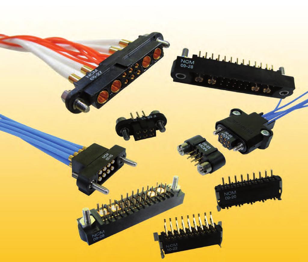

1 MICRO-CONNECTOR CMM SERIES
2 CMM Series Micro-connectors NICOMATIC specializes in the design, development and manufacture of electronic connectors. The CMM MICRO CONNECTOR interconnection system is a 2mm pitch connector (square matrix) with proven high reliability under the most extreme environmental conditions: - Flexible architecture: "Board to Board", "Board towire" and "Wire towire" configurations - Modular and hybrid design: mixed layout full option with Low Frequency LF (over 5 Amp) and High Frequency HF - (over 11 GHz) and High Power - HP - (over 30 Amp) - High reliability contact design & High performance under harsh use conditions - Secure: integral jacking mechanism or locking by spring latch The CMM MICRO CONNECTOR is a complete and standard range of connectors: - CMM 100 series: 1 row from 2 to 25 LF contacts - CMM 200 series: 2 rows from 4 to 50 LF contacts - CMM 220 series: 2 rows from 4 to 60 LF contacts, or up to 15 HF or HP contacts (series 30) - CMM 320 series: 3 rows from 6 to 120 LF contacts, or up to 20 HF or HP contacts (series 30) - CMM 340 series: 3 rows min. 6 LF contacts and up to 64 HF or HP contacts (series 22) Direct benefits: - Space saving: - 40% in surface and over - 60% in volume - Weight saving: - 20 to - 50% vs. usual solution for same functionalities - Reduce number of connectors: 2 or 3 connectors in 1 thanks to a modular concept - Cost effective solution: custom connector assembly from standard components - Proven success stories in on-board electronic systems - Full traceability with EN9100: Short lead time: 1 week express service, Premium service, Fast sampling and prototyping Over 15 million standard arrangements! - Online services ( Free use of My Nicomatic service (2D & 3D drawings), automatic part number & mating-half configurators, technical support under technic@nicomatic.fr The CMM has been developed for the aerospace, avionics, instrumentation & control, defence and transportation markets, with applications that include IFES, HUDs, flight controls, FADEC units, radars, missiles, electro-optical sighting systems, satellites, mobile radios, power supplies, UAVs and engine controls. It is also used in a growing number of medical, and telecom applications. 2


3 Dimension Tables CMM 100/200 SERIES in male & female styles for LF contacts CMM SERIES 100 & 200 Male LF contacts number series 100 LF contacts number series 200 Length in mm A Length in mm (Strap) B Length in mm C Length C with Latches fitted ,7 8,7 10,7 12,7 14,7 16,7 18,7 20,7 22,7 24,7 26,7 28,7 30,7 32,7 34,7 36,7 38,7 40,7 42,7 44,7 46,7 48,7 50,7 52,7 7,4 9,4 11,4 13,4 15,4 17,4 19,4 21,4 23,4 25,4 27,4 29,4 31,4 33,4 35,4 37,4 39,4 41,4 43,4 45,4 47,4 49,4 51,4 53,4 7,8 9,8 11,8 13,8 15,8 17,8 19,8 21,8 23,8 25,8 27,8 29,8 31,8 33,8 35,8 37,8 39,8 41,8 43,8 45,8 47,8 49,8 51,8 53,8 CMM SERIES 100 & 200 Female LF contacts number series 100 LF contacts number series 200 Length in mm A Length in mm B LF CONTACTS REFERENCE MARK NUMBER FOR CMM SERIES 200 Male & Female D E F G CMM 220 SERIES in male & female styles for LF contacts CMM SERIES 220 Male & Female LF contacts number Distance between axis Length in mm LF contacts reference mark number A B C D E F G CMM 220 SERIES in male & female styles for HF/HP contacts CMM 220 Male & Female Special contacts only Special contacts number Distance between axis Length in mm A B C CMM 320 SERIES in male & female styles for LF contacts CMM SERIES 320 Male & Female LF contacts number Distance between axis Length in mm LF contacts reference mark number A B C D E F G H J CMM 340 SERIES in male & female styles for HF/HP contacts CMM 340 Male & Female Special contacts only Special contacts number Distance between axis Length in mm A B C ,5 5 7, , , , , , , , , , , , , , ,5 12, , , , , , , , , , , , , , , ,5 18, , , , , , , , , , , , , , , ,5 3
4 CMM Specifications (with LF contacts) MATERIALS INSULATOR: Special PPS (Polyphenylene Sulfide Fiberglass filled thermoplastic) UL 94-V0 Radiation resistance No humidity absorption Oxygen free Note : PPS characteristics are recognized for space applications P.C. LF CONTACTS : Male: Female: Tail : copper alloy / Ni + Au flash 0,1µ Body : copper alloy / Ni + Au 0,2 µ Contact area : copper alloy / Ni + Au > 1µ Socket : beryllium copper / Ni + Au > 1,25µ CRIMP LF CONTACTS : Male: Female: Body : copper alloy / Ni + Au > 1µ Body : copper alloy / Ni + Au > 0,2 µ Socket : beryllium copper / Ni + Au > 1,25µ FIXING HARDWARE: Jackscrew: Stainless steel. Latch : Beryllium copper/plated nickel (CMM 100/200 series only) ELECTRICAL All contacts 3 A 25 C 2.2 A 85 C Working voltage (sea level) Proof voltage Contact resistance (initially) Insulation resistance MECHANICAL Tested at 800 V DC Tested at V DC max. 10 mω MΩ min. Mechanical operations Contact insertion and withdrawal force Contact retention in insulator Contact replacement in insulator ENVIRONMENTAL Up to 2500 cycles 2 N max. / 0.2 N min. per contact 10 N min. 3 cycles (Crimp contacts only) Temperature range From - 60 C to C Reflow solder process compatible (+260 C) Vibration severity Shock severity Solvent resistance 0.75 mm, 10 g RMS 6 hours long random with superimposed sinusoid. No intermittencies measured when using an H.S.L.I (High Speed Logic Interrupt) detector with a trip threshold of 2 ns. MIL-DTL-55302F Test Condition III [147.1 m/s2 (15 gn) peak] 100 g for 6 ms HcFc 141 bmgx (ATOCHEM) solvent Note : The CMM micro-connectors are designed to meet or exceed the relevant electrical and environmental performances described in MIL-DTL-55302F & BS-9525-F0033 standards. 4
5 HF / HP contacts specifications MATERIALS Spring loaded parts Other metal parts Insulator Retaining clip MECHANICAL Mechanical operations Insertion force Withdrawal force Secure overlapping Contact replacement in insulator Be/Cu gold plated Copper alloy PTFE (HF) Be/Cu Ni plated Up to 2500 cycles From 0.60 to 5 N per contact From 0.50 to 2 N per contact 1.30 mm 50 cycles for HF / HP 30 series (5 cycles for HF / HP 22 series) ELECTRICAL High Power (HP) Contact ENVIRONMENTAL } High Frequency (HF) Contact Intensity Series 30 : 20 A Impedance 50Ω / 75Ω depending on cable Series 22 : 10 A Insulation resistance 106 MΩ / 250 V (RMS) Contact resistance max. 6 mω SWR (Stationary wave rate) < F (GHz) Maximum voltage (sea level) 1000 V (RMS) Frequency range Series 30 : 6 GHz Operating voltage (sea level) 180 V AC/500 ma Series 22 : 1,5 GHz Insulation between 2 contacts -100 db (depending on cable) } depending on cable Temperature range Salt spray test Humidity test From -60 C to +260 C 96 hrs 56 90% humidity HF / HP CONTACTS PART NUMBERING 30 = series 30 [ø 3mm] (CMM 220 / 320) 22 = series 22 [ø 2.2mm] (CMM 340) These two digits are linked to the connector Do not use them inside a CMM part number (when loaded) Special contacts : 1 = male HF 2 = female HF 3 = male HP 4 = female HP Contact type : 3 = Straight 4 = Right Angle 5 = SMT Right Angle 6 = SMT straight - - Termination length (only for PCB contacts) CMM = standard 3 mm 45 = 4,5 mm Contact termination : 00 = PCB, xx = cable diameter x 10 Important notice: According to the routines test other than MIL our technical features for CMM Micro-connectors reach a higher result. Please contact technic@nicomatic.fr for more information. For example: - LF: up to 5A max.@ 25 C - HF: up to 11 GHz - HP: up to 30 A - Mechanical operations: up to cycles - High temperature test: 1 000H at 250 C - Application with LVDS 400 MHz, impedance 100 Ohm - High speed: USB, 1Gb/s Ethernet 5
 Meets or exceeds the relevant electrical & environmental")
6 HIGHLIGHT ON CMM CONNECTOR BENEFITS Unlimited style of connector: - Mixed-layout: High, Low frequency & High power in 1 connector - PCB solder, SMT, press fit, crimp contacts - Board to board, board to wire, wire to wire connections - Very small footprint: 2 mm pitch (saves up to 60% space & 50% weight over conventional connectors) Meets or exceeds the relevant electrical & environmental performances described in MIL-DTL-55302F & BS-9525-F0033 standards Excellent mechanical & environmental characteristics Built-in jackscrews for high vibrations Resistance to solvents, radiations & oxygen free Allows infrared, wave or vapour phase soldering High reliability contact design: up to cycles RoHS & Whiskers free (all contacts are gold plated) Short lead time: 1 week delivery service 100% quality control Proven track record in defense, aerospace & railway as well as other high reliability or technology field applications Connector housing marking for full traceability Large range of accessories & tools 6


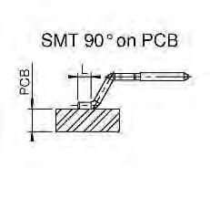
7 LF : low frequency contacts PRESENTATION Female Male Straight PCB Type Y 90 PCB Type V Straight SMT Type T 90 SMT Type R Crimp Type S - C Straight PCB Type PF Press fit INFORMATION TABLE CMM RANGE USE STRAIGHT ON PCB 90 ON PCB STRAIGHT SMT 90 SMT CRIMP Male Y YL YM YX V VL T TL R C S 100/200 L=3,0 L=4,5 L=5,1 L=9,1 L=3,0 L=4,5 L=2,25 L=3,35 L=0,9 Gauge 22 Gauge Female Y YL YC PF V VL T TL R C S L=3,0 L=4,5 L=1,2 Press fit L=3,0 L=4,5 L=2,25 L=3,35 L=0,9 Gauge 22 Gauge Male Y YL YM YX V VL T TL R C S L=3,0 L=4,5 L=5,1 L=9,1 L=3,0 L=4,5 L=2,25 L=3,35 L=0,9 Gauge 22 Gauge Female Y YL YC PF V VL T TL R C S L=3,0 L=4,5 L=1,2 Press fit L=3,0 L=4,5 L=2,25 L=3,35 L=0,9 Gauge 22 Gauge Male Y YL YM YX V VL R C S L=3,0 L=4,5 L=5,1 L=9,1 L=3,0 L=4,5 L=0,9 Gauge 22 Gauge Female Y YL PF V VL C S L=3,0 L=4,5 Press fit L=3,0 L=4,5 Gauge 22 Gauge Male Y YL YM YX V VL C S L=3,0 L=4,5 L=5,1 L=9,1 L=3,0 L=4,5 Gauge 22 Gauge Female Y YL PF V VL C S L=3,0 L=4,5 Press fit L=3,0 L=4,5 Gauge 22 Gauge L=6,50 / 8,00 / 10,50 / 12,00 / 14,50 / 16,00 mm upon request (only for straight on pcb male contacts) Standard contact Any other type of contact upon request only 7


 TYPE E FOR SPECIAL CONTACTS ON CABLE")


8 PRESENTATION HF : high frequency contacts (series 30) Female Male Straight PCB 90 PCB Straight SMT 90 SMT Card edge Type D Straight Crimp 90 Crimp Straight solder 90 solder Type E INFORMATION TABLE CMM RANGE TYPICAL USE TYPE OF CONTACTS TO BE USED IN THE CMM CONNECTOR WITH CAVITIES FOR HF/HP CONTACTS ONLY TYPE D FOR SPECIAL CONTACTS ON PCB (Eg.221D00F22-00 nbr of special contact-1300cmm) TYPE E FOR SPECIAL CONTACTS ON CABLE Straight on PCB 90 on PCB Straight SMT 90 SMT Card edge Straight Crimp 90 Crimp Straight solder 90 solder 100/ Male Female Male Female Male Female Male Female CMM CMM CMM 30-13XX-SS 30-14XX-ZS 30-13XX-ZZ 30-14XX-ZZ L=3,0 L=4,5 L=3,0 L=4, no LF contact XX-DS 30-14XX-DS xx=cable type xx=cable type xx=cable type xx=cable type CMM CMM XX-SS 30-24XX-ZS 30-23XX-ZZ 30-24XX-ZZ L=3,0 L=4,5 L=3,0 L=4, XX-DS 30-24XX-DS xx=cable type xx=cable type xx=cable type xx=cable type CMM CMM XX-SS 30-14XX-ZS 30-13XX-ZZ 30-14XX-ZZ L=3,0 L=4,5 L=3,0 L=4, XX-DS 30-14XX-DS xx=cable type xx=cable type xx=cable type xx=cable type CMM XX-SS 30-24XX-ZS 30-23XX-ZZ 30-24XX-ZZ L=3,0 L=4,5 L=3,0 L=4, XX-DS 30-24XX-DS xx=cable type xx=cable type xx=cable type xx=cable type Standard contact Any other type of contact upon request only XX = 12, 20, 24, 26 Eg. 24 = cable Ø 2,4 XX = 20 or 26 for DS cable Central contact S = crimp Z = solder XX = 47, 85 Eg. 47 for UT47 cable Shield S = crimp Z = solder { Double shield DS 8


9 PRESENTATION HP : high power contacts (series 30) Female Male Straight PCB 90 PCB Straight SMT 90 SMT 90 SMT Card edge Type D Straight Crimp 90 Crimp Straight solder 90 solder Type E INFORMATION TABLE CMM RANGE TYPICAL USE TYPE OF CONTACTS TO BE USED IN THE CMM CONNECTOR WITH CAVITIES FOR HF/HP CONTACTS ONLY TYPE D FOR SPECIAL CONTACTS ON PCB TYPE E FOR SPECIAL CONTACTS ON CABLE Straight on PCB 90 on PCB Straight SMT 90 SMT 90 SMT Card edge Straight Crimp 90 Crimp Straight solder 90 solder 100/ Male Female Male Female Male Female Male Female CMM CMM CMM L=3,0 L=4,5 L=3,0 L=4, no LF contact XX 30-33XX CMM CMM L=3,0 L=4,5 L=3,0 L=4, XX 30-43XX CMM CMM L=3,0 L=4,5 L=3,0 L=4, XX 30-33XX CMM L=3,0 L=4,5 L=3,0 L=4, XX 30-43XX Standard contact Any other type of contact upon request only XX = 05, 08 Eg. 08 for 8A Please refer to page 94 9


10 PRESENTATION HF : high frequency contacts (series 22) Female Male Straight PCB 90 PCB Straight SMT 90 SMT Straight Crimp 90 Crimp Straight solder 90 solder Type D Type E INFORMATION TABLE CMM RANGE TYPICAL USE TYPE OF CONTACTS TO BE USED IN THE CMM CONNECTOR WITH CAVITIES FOR HF/HP CONTACTS ONLY TYPE D FOR SPECIAL CONTACTS ON PCB TYPE E FOR SPECIAL CONTACTS ON CABLE Straight on PCB 90 on PCB Straight SMT 90 SMT Straight Crimp 90 Crimp Straight solder 90 solder 100/ Male Female Male Female Male Female Male Female * * L=3,0 L=4, ** ** ZS ZZ L=3,0 L=4, * * L=3,0 L=4, ** ** ZS ZZ L=3,0 L=4,5 Standard contact Any other type of contact upon request only * First row : / / / ** Second row : / / / = cable Ø 1,2 20 = cable Ø 2,0 10 When a two-row connector mixes a and a contact, the P/N of the HF contact changes to When a two-row connector mixes a and a contact, the P/N of the HF contact changes to When a two-row connector mixes a and a contact, the P/N of the HF contact changes to When a two-row connector mixes a and a contact, the P/N of the HF contact changes to


11 PRESENTATION HP : high power contacts (series 22) Female Male Straight PCB 90 PCB Straight SMT 90 SMT Straight Crimp 90 Crimp Straight solder 90 solder Type D Type E INFORMATION TABLE CMM RANGE TYPICAL USE TYPE OF CONTACTS TO BE USED IN THE CMM CONNECTOR WITH CAVITIES FOR HF/HP CONTACTS ONLY TYPE D FOR SPECIAL CONTACTS ON PCB TYPE E FOR SPECIAL CONTACTS ON CABLE Straight on PCB 90 on PCB Straight SMT 90 SMT Straight Crimp 90 Crimp Straight solder 90 solder 100/ Male Female Male Female Male Female Male Female * * L=3,0 L=4, ** ** 22-33XX 22-33XX L=3,0 L=4, * * L=3,0 L=4, ** ** 22-43XX 22-43XX L=3,0 L=4,5 Standard contact Any other type of contact upon request only * First row : / / / ** Second row : / / / XX = 05, 08, = 10A Please refer to page 102 When a two-row connector mixes a and a contact, the P/N of the HF contact changes to When a two-row connector mixes a and a contact, the P/N of the HF contact changes to When a two-row connector mixes a and a contact, the P/N of the HF contact changes to When a two-row connector mixes a and a contact, the P/N of the HF contact changes to
 Marking on two faces if the number (LF contacts only) Connector P/N of LF contacts is < to 10.")
 CMM 220 with HF/HP contacts CMM 220 with 04 LF contacts Marking LF contacts type : Y-YL-V-VL-R-T-S-C CMM 320/340")
 / date code (Lot number) : CMM 320 mixed layout (as for CMM 100/200) CMM 320 with HF/HP contacts CMM 340 Marking LF")
12 Male housing marking CMM 100/200 Marking : NCM (Nicomatic) + date code (Lot number) CMM 220 Marking 1 : NCM (Nicomatic) + date code (Lot number) Marking on two faces if the number (LF contacts only) Connector P/N of LF contacts is < to 10. LF contact number 1 Marking 2 : NCM (Nicomatic) + date code (Lot number) : CMM 220 mixed layout (LF + HF/HP) (as for CMM 100/200) CMM 220 with HF/HP contacts CMM 220 with 04 LF contacts Marking LF contacts type : Y-YL-V-VL-R-T-S-C CMM 320/340 Marking 1 : NCM (Nicomatic) / date code (Lot number) Connector P/N LF contact number 1 (LF contacts only) 12 Marking 2 : NCM (Nicomatic) / date code (Lot number) : CMM 320 mixed layout (as for CMM 100/200) CMM 320 with HF/HP contacts CMM 340 Marking LF contacts type : Y-YL-V-VL-S-C
 Marking on two faces if the number (LF contacts only) Connector P/N of LF contacts is < to 10.")

 : CMM 320 mixed layout HF/HP contacts (as for CMM 100/200) CMM 320 with HF/HP contacts CMM 340 Marking LF contacts")
13 Female housing marking CMM 100/200 Marking : NCM (Nicomatic) + date code (Lot number) CMM 220 Marking 1 : NCM (Nicomatic) + date code (Lot number) Marking on two faces if the number (LF contacts only) Connector P/N of LF contacts is < to 10. LF contact number 1 Marking 2 : NCM (Nicomatic) + date code (Lot number) : CMM 220 mixed layout (LF + HF/HP) (as for CMM 100/200) CMM 220 with HF/HP contacts CMM 220 with 04 LF contacts Marking LF contacts type : Y-YL-V-VL-R-T-S-C-PF CMM 320/340 Marking 1 : NCM (Nicomatic) / date code (Lot number) (LF contacts only) Connector P/N LF contact number 1 Marking 2 : NCM (Nicomatic) / date code (Lot number) : CMM 320 mixed layout HF/HP contacts (as for CMM 100/200) CMM 320 with HF/HP contacts CMM 340 Marking LF contacts type : Y-YL-V-VL-S-C-PF 13
 Number of HF/HP contacts opposite to LF contact number 1 HF/HP Contact Type n n n y y z z 1 row 2 rows 10 20 1 male 2 female 1 male 2 female Refer to table")
14 Nicomatic CMM part Code with Low Frequency contacts only Additional code for mixed-layout connector (HF/HP) Series Gender Termination Style Number of LF contacts Fixing Hardware Number of HF/HP contacts pin 1 side (LF contact number 1) Number of HF/HP contacts opposite to LF contact number 1 HF/HP Contact Type n n n y y z z 1 row 2 rows male 2 female 1 male 2 female Refer to table on page 7 Refer to table on page 7 02 to 25 (nn) 04 to 50 (nn) With Latch page 22 Without Latch With Latch page 22 Without Latch No HF / HP contacts 2 rows 22 1 male 2 female Refer to table on page 7 04 to 60 (nn) Refer to pages 43 to 46 Depends upon the number of LF contacts If use with shifted central key, please refer to page 38 HF / HP : 15 contacts max. Type of HF/HP contact : please refer to pages 8-9 Coaxmatic 30 3 rows 32 1 male 2 female Refer to table on page to 120 (nnn) Refer to pages 69 to 74 Depends upon the number of LF contacts HF / HP : 20 contacts max. Type of HF/HP contact : please refer to pages 8-9 Coaxmatic 30 3 rows 34 1 male 2 female Refer to table on page 7 Refer to the series 320 (nnn) Refer to pages 69 to 74 Depends upon the number of LF contacts HF / HP : 64 contacts max. Type of HF/HP contact : please refer to pages Coaxmatic 22 Note : For any configuration outside of this part numbering system, please contact us. 14
 (HP) Tools and accessories p.")
15 numbering system CMM 100/200 Series p. 17 to 25 CMM 220 Series p. 27 to 46 CMM 320 Series p. 47 to 59 CMM 340 Series p. 60 to 74 High Frequency and High Power contacts p. 75 to 102 (HF) (HP) Tools and accessories p. 103 to 112 Cable instructions & assembly p. 113 to
16 16

17 CMM 100 / 200 PART NUMBERING REMINDER Code with Low Frequency contacts only Series Gender Termination Style Number of LF contacts Fixing Hardware n n 1 row 2 rows male 2 female 1 male 2 female Refer to table on page 7 Refer to table on page 7 02 to to 50 With Latch L, FL, LS page 22 Without Latch With Latch L, FL, LS page 22 Without Latch 17


18 CONNECTOR SPACING Configuration CMM 100 without latch only without latch only CONTACTS POSITIONS 18

19 CONNECTOR SPACING Configuration CMM 200 without latch only without latch only CONTACTS POSITIONS 19
20 CMM 100 / 200 male STRAIGHT PCB 0 1 n n 1 = Series = Series 200 Type : Y-YL L, FL = with latch page 22 = without latch nn = number of LF contacts Type L Y 3 YL 4,5 Calculation : CMM 100 CMM 200 A = (nn x 2) - 2 A = nn - 2 B = A + 4,7 B = A + 4,7 C = A + 5,4 C = A + 5,4 Refer to dimension table on cover page nn min = 02 nn max = 25 nn min = 04 nn max = PCB 0 1 n n 1 = Series = Series 200 Type :V-VL L, FL = with latch page 22 = without latch nn = number of LF contacts Type L V 3 VL 4,5 Calculation : CMM 100 CMM 200 A = (nn x 2) - 2 A = nn - 2 B = A + 4,7 B = A + 4,7 C = A + 5,4 C = A + 5,4 Refer to dimension table on cover page nn min = 02 nn max = 25 nn min = 04 nn max = 50 20


21 CMM 100 / 200 male STRAIGHT SMT 0 1 n n 1 = Series = Series 200 Type :T-TL LS, L, FL = with latch page 22 = without latch nn = number of LF contacts Calculation : CMM 100 CMM 200 A = (nn x 2) - 2 A = nn - 2 C = A + 5,4 C = A + 5,4 Refer to dimension table on cover page nn min = 02 nn max = 25 nn min = 04 nn max = SMT 0 1 R n n 1 = Series = Series 200 LS, L, FL = with latch page 22 = without latch nn = number of LF contacts Calculation : CMM 100 CMM 200 A = (nn x 2) - 2 A = nn - 2 C = A + 5,4 C = A + 5,4 Refer to dimension table on cover page nn min = 02 nn max = 25 nn min = 04 nn max = 50 21


22 CMM 100 / 200 male CRIMP 0 1 n n Type Calculation : Type : S-C Gauge S C 22 1 = Series = Series 200 L, FL = with latch page 22 = without latch nn = number of LF contacts CMM 100 CMM 200 A = (nn x 2) - 2 A = nn - 2 C = A + 5,4 C = A + 5,4 Refer to dimension table on cover page nn min = 02 nn max = 25 nn min = 04 nn max = 50 RETENTION LATCHES FOR CMM 100 / 200 MALE Straight latch with locking L Straight latch without locking FL Latch for CMM connector with T termination style LS Latch for CMM connector with R termination style LS The strain relief straps are supplied with all male CMM 100 / 200 connectors mounted with latches L or FL type except for Y & YL terminations 22 PCB Thickness P/N Termination style < 2,5 mm V Y T/TL R > 2,5 mm VL YL T/TL R If no strain relief straps with your connector, please order under P/Ns on the left
23 CMM 100 / 200 female STRAIGHT PCB 0 2 n n 1 = Series = Series 200 Type : Y-YL Type L Y 3 YL 4,5 nn = number of LF contacts Calculation : CMM 100 CMM 200 A = (nn x 2) - 2 A = nn - 2 B = A + 5 B = A + 5 Refer to dimension table on cover page 90 PCB 0 2 n n 1 = Series = Series 200 nn min = 02 nn max = 25 nn min = 04 nn max = 50 Type :V-VL Type L V 3 VL 4,5 nn = number of LF contacts Calculation : CMM 100 CMM 200 A = (nn x 2) - 2 A = nn - 2 B = A + 5 B = A + 5 Refer to dimension table on cover page nn min = 02 nn max = 25 nn min = 04 nn max = 50 23
24 CMM 100 / 200 female STRAIGHT SMT 0 2 n n 1 = Series = Series 200 Type : T-TL nn = number of LF contacts Calculation : CMM 100 CMM 200 A = (nn x 2) - 2 A = nn - 2 B = A + 5 B = A + 5 Refer to dimension table on cover page Optional: Packaging in reel available upon request CRIMP 0 2 n n 1 = Series100 2 = Series 200 nn min = 02 nn max = 25 nn min = 04 nn max = 50 Type : S-C nn = number of LF contacts Type Gauge S C 22 Calculation : CMM 100 CMM 200 A = (nn x 2) - 2 A = nn - 2 B = A + 5 B = A + 5 Refer to dimension table on cover page nn min = 02 nn max = 25 nn min = 04 nn max = 50 24

25 CMM 100 / 200 female STRAIGHT PRESS FIT 0 2 PF n n 1 = Series = Series 200 nn = number of LF contacts Calculation : CMM 100 CMM 200 A = (nn x 2) - 2 A = nn - 2 B = A + 5 B = A + 5 Refer to dimension table on cover page nn min = 02 nn max = 25 nn min = 04 nn max = SMT 0 2 R n n 1 = Series = Series 200 nn = number of LF contacts Optional: Packaging in reel available upon request nn min = 02 nn max = 25 nn min = 04 nn max = 50 Upon request only 25
26 26

27 CMM 220 with LF contacts PART NUMBERING REMINDER Code with Low Frequency contacts only Series Gender Termination Style Number of LF contacts Fixing Hardware n n 2 rows 22 1 male 2 female Refer to table on page 7 04 to 60 Refer to pages 43 to 46 27


28 CONNECTOR SPACING CMM 220 Configuration CONTACTS POSITIONS 28
29 CMM 220 male STRAIGHT PCB n n nn min = 04 nn max = 60 Type : Y-YL See Fixing on page 43, 44 Fxx without fixing nn = number of LF contacts Type L Y 3 YL 4,5 Calculation : A = nn - 2 B = A + 7 C = A + 12 Refer to dimension table on cover page 90 PCB n n nn = number of LF contacts Type L V 3 VL 4,5 nn min = 04 nn max = 60 Type : V-VL See Fixing on page 43, 44 Fxx without fixing Calculation : A = nn - 2 B = A + 7 C = A + 12 Refer to dimension table on cover page 29
30 CMM 220 male STRAIGHT SMT Type : T-TL n n nn min = 04 nn max = 60 See Fixing on page 43, 44 Fxx without fixing nn = number of LF contacts Optional: Packaging in reel available upon request Calculation : A = nn - 2 B = A + 7 C = A + 12 Refer to dimension table on cover page 90 SMT nn min = 04 nn max = R n n See Fixing on page 43, 44 Fxx without fixing nn = number of LF contacts Optional: Packaging in reel available upon request Calculation : A = nn - 2 B = A + 7 C = A + 12 Refer to dimension table on cover page 30

31 CMM 220 male CRIMP n n nn = number of LF contacts nn min = 04 nn max = 60 Type : S-C See Fixing on page 43, 44 Fxx without fixing Type Gauge S C 22 Calculation : A = nn - 2 B = A + 7 C = A + 12 Refer to dimension table on cover page 31
32 CMM 220 female STRAIGHT PCB n n nn = number of LF contacts nn min = 04 nn max = 60 Type : Y-YL See Fixing on page Mxx without fixing Type L Y 3 YL 4,5 Calculation : A = nn - 2 B = A + 7 C = A + 12 Refer to dimension table on cover page 90 PCB n n nn = number of LF contacts nn min = 04 nn max = 60 Type : V-VL See Fixing on page 45 Mxx without fixing Type L V 3 VL 4,5 Calculation : A = nn - 2 B = A + 7 C = A + 12 Refer to dimension table on cover page 32

33 CMM 220 female STRAIGHT SMT Type : T-TL n n nn min = 04 nn max = 60 See Fixing on page Mxx without fixing nn = number of LF contacts Optional: Packaging in reel available upon request Calculation : A = nn - 2 B = A + 7 C = A + 12 Refer to dimension table on cover page 90 SMT R n n nn min = 04 nn max = 60 See Fixing on page 45 Mxx without fixing nn = number of LF contacts Optional: Packaging in reel available upon request Calculation : A = nn - 2 B = A + 7 C = A + 12 Refer to dimension table on cover page 33
34 CMM 220 female STRAIGHT PRESS FIT PF n n See Fixing on page Mxx without fixing nn = number of LF contacts nn min = 04 nn max = 60 Calculation : A = nn - 2 B = A + 7 C = A + 12 Refer to dimension table on cover page CRIMP n n nn = number of LF contacts nn min = 04 nn max = 60 Type : S-C See Fixing on page Mxx without fixing Type Calculation : A = nn - 2 B = A + 7 C = A + 12 Gauge S C 22 Refer to dimension table on cover page 34
 Number of HF/HP contacts pin 1 side (LF contact number 1) Number of HF/HP contacts opposite to LF contact number 1 HF/HP Contact Type n n y y z z 2 rows 22 1 male 2 female Refer to table on")
35 CMM 220 mixed-layout PART NUMBERING REMINDER Series Code with Low Frequency contacts only Gender Termination Style Number of LF contacts Fixing Hardware Additional code for mixed-layout connector (HF/HP) Number of HF/HP contacts pin 1 side (LF contact number 1) Number of HF/HP contacts opposite to LF contact number 1 HF/HP Contact Type n n y y z z 2 rows 22 1 male 2 female Refer to table on page 7 04 to 60 Refer to pages 43 to 46 Depends upon the number of LF contacts If use with shifted central key, please refer to page 42 HF / HP : 15 contacts max. Type of HF/HP contact : please refer to pages 8-9 HP/HF 30 please refer to pages 75 to 94 35
36 CMM 220 Male mixed-layout STRAIGHT PCB Number of contacts LF pin 1 side n n - y y z z - Number of contacts opposite side LF pin 1 Type : Y-YL See Fixing on page 43, 44 Fxx without fixing nn = number of LF contacts Type L Y 3 YL 4,5 HF or HP P/N refer to page 75 Pattern for special contact : A = nn - 2 B = {(yy+zz)x4} + A + 7 Bmax. = 65 mm C = B + 5 STRAIGHT PCB FOR HP/HF CONTACTS ONLY D z z - Number of HF or HP contacts See Fixing on page 43, 44 Fxx without fixing HF or HP P/N refer to page 75 Pattern for special contact : A = (zz x 4) - 4 B = A + 9 C = B + 5 Special contacts min. : 02 max. : 15 Refer to dimension table on cover page 36
37 CMM 220 Male mixed-layout 90 PCB Number of contacts LF pin 1 side n n - y y z z - Number of contacts opposite side LF pin 1 Type : V-VL See Fixing on page 43, 44 Fxx without fixing nn = number of LF contacts Type L V 3 VL 4,5 HF or HP P/N refer to page 75 Pattern for special contact : A = nn - 2 B = {(yy+zz)x4} + A + 7 Bmax. = 65 mm C = B PCB FOR HP/HF CONTACTS ONLY D z z - Number of HF or HP contacts See Fixing on page 43, 44 Fxx without fixing HF or HP P/N refer to page 75 Pattern for special contact : A = (zz x 4) - 4 B = A + 9 C = B + 5 Special contacts min. : 02 max. : 15 Refer to sizes information table on cover page 37
x4}")

38 CMM 220 Male mixed-layout CRIMP Number of contacts LF pin 1 side n n - y y z z - Number of contacts opposite side LF pin 1 Type : S-C See Fixing on page 43, 44 Fxx without fixing nn = number of LF contacts Type Gauge S C 22 HF or HP P/N refer to page 75 A = nn - 2 B = {(yy+zz)x4} + A + 7 Bmax. = 65 mm C = B + 5 CRIMP FOR HP/HF CONTACTS ONLY E z z - Number of HF or HP contacts See Fixing on page 43, 44 Fxx without fixing HF or HP P/N refer to page 75 A = (zz x 4) - 4 B = A + 9 C = B + 5 Special contacts min. : 02 max. : 15 Refer to dimension table on cover page 38
39 STRAIGHT PCB CMM 220 Female mixed-layout Number of contacts LF pin 1 side n n - y y z z - Number of contacts opposite side LF pin 1 Type : Y-YL See Fixing on page 45 Mxx without fixing nn = number of LF contacts Type L Y 3 YL 4,5 HF or HP P/N refer to page 75 Pattern for special contact : A = nn - 2 B = {(yy+zz)x4} + A + 7 Bmax. = 65 mm C = B + 5 STRAIGHT PCB FOR HP/HF CONTACTS ONLY D z z - Number of HF or HP contacts See Fixing on page 45 Mxx without fixing HF or HP P/N refer to page 75 Pattern for special contact : A = (zz x 4) - 4 B = A + 9 C = B + 5 Special contacts min. : 02 max. : 15 Refer to dimension table on cover page 39
40 CMM 220 Female mixed-layout 90 PCB Number of contacts LF pin 1 side n n - y y z z - Number of contacts opposite side LF pin 1 Type : V-VL See Fixing on page 45 Mxx without fixing nn = number of LF contacts Type L V 3 VL 4,5 HF or HP P/N refer to page 75 Pattern for special contact : A = nn - 2 B = {(yy+zz)x4} + A + 7 Bmax. = 65 mm C = B PCB FOR HP/HF CONTACTS ONLY D z z - Number of HF or HP contacts See Fixing on page 45 Mxx without fixing HF or HP P/N refer to page 75 Pattern for special contact : A = (zz x 4) - 4 B = A + 9 C = B + 5 Special contacts min. : 02 max. : 15 Refer to dimension table on cover page 40
x4} +")

41 CMM 220 Female mixed-layout CRIMP Number of contacts LF pin 1 side Number of contacts opposite side LF pin n n - y y z z - Type : S-C See Fixing on page 45 Mxx without fixing nn = number of LF contacts HF or HP P/N refer to page 75 Type Gauge S C 22 A = nn - 2 B = {(yy+zz)x4} + A + 7 Bmax. = 65 mm C = B + 5 CRIMP FOR HP/HF CONTACTS ONLY E z z - Number of HF or HP contacts See Fixing on page 45 Mxx without fixing HF or HP P/N refer to page 75 A = (zz x 4) - 4 B = A + 9 C = B + 5 Special contacts min. : 02 max. : 15 Refer to dimension table on cover page 41
 (k = 2 opposite direction to LF contact number 1) Polarized key shift")
42 Part numbering with shifted polarization key position PART NUMBERING Digits to be added Number of LF contacts nn min. = n n - y y z z - - k l l Polarized key direction shifted from the housing center (k = 1 direction of contact LF number 1) (k = 2 opposite direction to LF contact number 1) Polarized key shift value compared to the housing center (each shift = 2 mm) EXPLANATION Fxx Fxx Fxx EXAMPLES Fxx Mxx Fxx Mxx
 2 max.")


43 MALE CONNECTORS CMM SERIES 220 Type of contact in connector PCB Contacts Contacts on cable Type of PCB mount Straight 90 Straight 90 PCB thickness 0,8 min. 1,5 min ,5 4,5 1,6 3,2 0,8 min 1,5 min 6 4 2,5 4,5 1,6 3,2 (mm) 2 max. 4 max. max. max. max. max. max. max. 2 max 4 max max max max max max max Housing assembly FEMALE CONNECTORS CMM SERIES 220 Contacts on cable PCB Contacts Locked Smooth Locked Smooth With cover Without 90 Straight Floating Straight Without 90 Straight Straight Fixing hardware interconnection table for CMM 220 0,8 min. 2 max. 1,5 min. 4 max. 1,5 min. 2,5 max. 1,5 min. 4 max. 1,6 3,2 1,6 2 3,2 0,8 min. 2 max. 1,5 min. 4 max. 1,5 min. 2,5 max. 1,5 min. 4 max. 1,6 3,2 1,6 2 3,2 Fixing M12 M12H M12L M12LH M49 M49H M46 M46H M47 M47H M21 M21L M48 M48M M48L M16 M11 M12 M12L M49 M1xx M46 M47 M21 M21L M48 M48M M48L M16 M11 M18 Card edge only HF Card edge HF & LF No fixing on PCB Racking F22 F24 F24L F25 F26 F30 F31 F63 F63L F27 F34 F21 F60 F61 F62 F22 F24 F24L F25 F26 F30 F31 F63 F63L F2xx F21 F60 F61F62 F28 F22H F24H F23 F30H F31H F62H F23 F30H F31H OK OK OK OK OK OK OK OK OK OK OK OK OK OK OK OK OK OK OK OK OK OK OK OK OK OK OK OK OK OK OK OK OK OK OK OK OK OK OK OK OK OK OK OK OK OK OK OK OK OK OK OK OK OK OK OK OK OK OK OK OK OK OK OK OK OK OK OK OK OK OK OK OK OK OK OK OK OK OK OK OK OK OK OK OK OK OK OK OK OK OK OK OK OK OK OK OK OK OK OK OK OK OK OK OK OK OK OK OK OK OK OK OK OK OK OK OK OK OK A A A OK OK OK A A A OK OK B OK OK OK A A A OK OK OK A A A OK OK B OK OK OK OK OK OK OK OK OK OK OK OK OK OK OK OK OK OK OK OK OK OK OK OK OK OK OK OK OK OK OK OK OK OK OK OK OK OK OK OK OK OK OK OK OK OK OK OK OK OK OK OK OK OK OK OK OK OK OK OK OK OK OK OK OK OK OK OK OK OK OK OK OK OK OK OK OK OK OK OK OK OK OK OK OK OK OK OK OK OK OK OK OK OK OK OK OK OK OK OK OK OK OK OK OK OK OK A A A OK OK OK A A A OK OK B OK OK OK A A A OK OK OK A A A OK OK B OK OK OK OK OK OK OK OK OK OK OK OK OK OK OK OK OK OK OK OK OK OK OK OK OK OK OK B B B OK OK OK OK OK OK B B B OK OK OK Make it a habit! Use easy & automatic configurators for CMM micro-connectors single part and mating-half construction on Floating No fixing on PCB Racking With cover FIXING HARDWARE FOR CMM 220 MALE Recommended Torque : 0,2 N/m Except 0,4 N/m for M46/M47 REFERENCE ASSEMBLY ON PCB OVERALL DIMENSIONS RECOMMENDATION F27 F27 : CMM male : Card edge for HF contact CMM F34 F34 : CMM male : Card edge LF contact or mixed F28 : CMM male : S-C (E : straight) F28 Please refer to the CMM Catalogue Guidelines for any other fixing not listed here. 43


 F24 : CMM")
 F24L :")
 x 10")
 x 10 = 32 xx = 32 F25")

 F26 F23 90 on PCB F26/F23 :")

 F31 F31H 90 on PCB 4,5 max.")
 44 Please refer to the CMM")
44 Fixing for CMM 220 male FIXING HARDWARE FOR CMM 220 MALE REFERENCE ASSEMBLY ON PCB OVERALL DIMENSIONS RECOMMENDATION F21 Straight on PCB F21 : CMM male : Y-YL-T-S-C (D-E : straight) F22 F22H F24 F24H F24L Straight on PCB 0,8 min / 2 max Straight on PCB 1,5 min / 4 max Straight on PCB 6 max F22 : CMM male : Y-T-S-C (D-E : straight) F22H : CMM male : Y-T (D : straight) F24 : CMM male : YL-T-S-C (D-E : straight) F24H : CMM male : YL-T (D : straight) F24L : CMM male : T-TL (D-E : straight) F2xx xx = (PCB thickness + 0,2 mm) x 10 Example : for 3 mm PCB, the reference is F232 (3 + 0,2) x 10 = 32 xx = 32 F25 Straight on PCB with floating option 90 on PCB F2xx : CMM male : S-C (E : straight) F25 : CMM male : V-VL-R-S-C-E (D : 90 ) F26 F23 90 on PCB F26/F23 : CMM male : V-VL-R-S-C-E (D : 90 ) F30 F30H 90 on PCB 2,5 max. F30 & F30H: CMM male : V-R-C-S-E (D : 90 ) F31 F31H 90 on PCB 4,5 max. F31 & F31H: CMM male : VL-R-C-S-E (D : 90 ) 44 Please refer to the CMM Catalogue Guidelines for any other fixing not listed here.


 M12 M12H")
")
 M12L M12LH Straight on PCB")
 M1xx xx")


 M21 for PCB 1,6 mm (L = 4")

 M18 Cover option")

45 Fixing for CMM 220 female FIXING HARDWARE FOR CMM 220 FEMALE HEXAGONAL NUT STANDARD NUT "W" CODE FOR ADDITIONAL WASHER REFERENCE ASSEMBLY ON PCB OVERALL DIMENSIONS RECOMMENDATION M11 M16 Straight on PCB M16/M11 : CMM Female : Y-YL-T-S-C-E (D : straight) M12 M12H Straight on PCB 0,8 min / 2 max M12 : CMM female : Y-T-S-C (D-E : straight) M12H : CMM female : Y-T (D : straight) M12L M12LH Straight on PCB 1,5 min / 4 max M12L : CMM female : Y-T-S-C (D-E : straight) M12LH : CMM female : YL-T (D : straight) M1xx xx = (PCB thickness + 0,2 mm) x 10 Example : for 3 mm PCB, the reference is M132 (3 + 0,2) x 10 = 32 xx = 32 Straight on PCB with floating option M1xx : CMM female : S-C (E : straight) M21 for PCB 1,6 mm (L = 4 mm) M21L for PCB 3,2 mm (L = 5 mm) 90 on PCB M21 : CMM Female : V-R-S-C-E (D : 90 ) M21L : CMM Female : VL-R-S-C-E (D : 90 ) M18 Cover option M18 : CMM female : S-C (E : straight) Please refer to the CMM Catalogue Guidelines for any other fixing not listed here. 45


 M48L for PCB 3,2")


 M47 : CMM")
 M47H : CMM female :")

 M49H : CMM")


 F62H : CMM male :")
")
46 Other fixing hardware for CMM 220 FIXING HARDWARE FOR CMM 220 FEMALE/MALE REFERENCE ASSEMBLY ON PCB OVERALL DIMENSIONS RECOMMENDATION M46 M46H M47 M47H M48 for PCB 1,6 mm (L = 3 mm) M48M for PCB 2 mm (L = 4 mm) M48L for PCB 3,2 mm (L = 5 mm) M49 M49H F60 Straight on PCB 1,5 min. / 2,5 max. Straight on PCB 1,5 min. / 4 max. 90 on PCB Straight on PCB Straight on PCB M46 : CMM female : Y-T-S-C (D-E : straight) M46H : CMM female : Y-T (D : straight) M47 : CMM female : YL-T-S-C (D-E : straight) M47H : CMM female : YL-T (D : straight) M48 / M48M / M48L : CMM female : V-VL-R-S-C-E (D : 90 ) M49 : CMM female : Y-T-S-C (D-E : straight) M49H : CMM female : Y-T (D : straight) F60 : CMM male : Y-YL-T-S-C-E (D : straight) F61 Straight on PCB F61 : CMM male : Y-YL-T-S-C-E (D : straight) F62 F62H F63 for PCB 1,6 mm F63L for PCB 3,2 mm Racking 90 on PCB M46 M46H M47 M47H F62 : CMM male : Y-T-S-C (D-E : straight) F62H : CMM male : Y-T (D : straight) F63 : CMM male : V-R-S-C-E (D : 90 ) F63L : CMM male : VL-R-S-C-E (D : 90 ) 46

47 CMM 320 with LF contacts PART NUMBERING REMINDER Code with Low Frequency contacts only Series Gender Termination Style Number of LF contacts Fixing Hardware n n n 3 rows 32 1 male 2 female Refer to table on page to 120 Refer to pages 69 to 74 47


48 CONNECTOR SPACING CMM 320 Configuration CONTACTS POSITIONS 48
49 CMM 320 Male STRAIGHT PCB FOR LF CONTACTS ONLY n n n Type : Y-YL See Fixing on pages 69 to 74 Fxx without fixing nnn = number of LF contacts Type L Y 3 YL 4,5 nnn min = 006 nnn max = 120 nnn x 2 A = B = A + 9 C = A + 15 Refer to dimension table on cover page 90 PCB FOR LF CONTACTS ONLY n n n Type : V-VL See Fixing on pages 69 to 74 Fxx without fixing nnn = number of LF contacts Type L V 3 VL 4,5 nnn min = 006 nnn max = 120 nnn x 2 A = B = A + 9 C = A + 15 Refer to dimension table on cover page 49


50 CMM 320 Male 90 SMT FOR LF CONTACTS ONLY R n n n See Fixing on pages 69 to 74 Fxx without fixing nnn = number of LF contacts Optional: Packaging in reel available upon request nnn min = 006 nnn max = 120 nnn x 2 A = B = A + 9 C = A + 15 Refer to dimension table on cover page CRIMP FOR LF CONTACTS ONLY Type : S-C n n n See Fixing on pages 69 to 74 Fxx without fixing nnn = number of LF contacts Type Gauge S C 22 nnn min = 006 nnn max = 120 nnn x 2 A = B = A + 9 C = A + 15 Refer to dimension table on cover page 50
51 CMM 320 Female STRAIGHT PCB FOR LF CONTACTS ONLY n n n Type : Y-YL See Fixing on pages 69 to 74 Mxx without fixing nnn = number of LF contacts Type L Y 3 YL 4,5 nnn min = 006 nnn max = 120 nnn x 2 A = B = A + 9 C = A + 15 Refer to dimension table on cover page 90 PCB FOR LF CONTACTS ONLY n n n Type : V-VL See Fixing on pages 69 to 74 Mxx without fixing nnn = number of LF contacts Type L V 3 VL 4,5 nnn min = 006 nnn max = 120 nnn x 2 A = B = A + 9 C = A + 15 Refer to dimension table on cover page 51


52 CMM 320 Female CRIMP FOR LF CONTACTS ONLY Type : S-C n n n See Fixing on pages 69 to 74 Mxx without fixing nnn = number of LF contacts Type Gauge S C 22 nnn min = 006 nnn max = 120 nnn x 2 A = B = A + 9 C = A + 15 Refer to dimension table on cover page 52
 Number of HF/HP contacts pin 1 side (LF contact number 1) Number of HF/HP contacts opposite to LF contact number 1 y y z z HF/HP Contact Type 3 rows 32 1 male 2 female Refer to")
53 CMM 320 with mixed-layout PART NUMBERING REMINDER Series Code with Low Frequency contacts only Gender Termination Style Number of LF contacts n n n Fixing Hardware Additional code for mixed-layout connector (HF/HP) Number of HF/HP contacts pin 1 side (LF contact number 1) Number of HF/HP contacts opposite to LF contact number 1 y y z z HF/HP Contact Type 3 rows 32 1 male 2 female Refer to table on page to 120 Refer to pages 69 to 74 Depends upon the number of LF contacts HF / HP : 20 contacts max. Type of HF/HP contact : please refer to pages 8-9 HF/HP 30 please refer to pages 75 to 94 53
54 CMM 320 Male mixed-layout STRAIGHT PCB Number of contacts LF pin 1 side n n n - y y z z - Number of contacts opposite side LF pin 1 Type : Y-YL See Fixing on pages 69 to 74 Fxx without fixing nnn = number of LF contacts Type L Y 3 YL 4,5 HF or HP P/N refer to page 75 Pattern for special contact : {(yy+zz)x4+nnn}x2 A = -2 3 B = A + 9 B max. = 87 C = A + 15 STRAIGHT PCB FOR HP/HF CONTACTS ONLY D z z - Number of HF or HP contacts See Fixing on pages 69 to 74 Fxx without fixing HF or HP P/N refer to page 75 Pattern for special contact : A = (zz x 4) - 4 B = A + 11 C = A + 17 Special contacts min. : 02 max. : 20 54
x4+nnn}x2 A =")

55 CMM 320 Male mixed-layout 90 PCB Number of contacts LF pin 1 side n n n - y y z z - Number of contacts opposite side LF pin 1 Type : V-VL See Fixing on pages 69 to 74 Fxx without fixing nnn = number of LF contacts Type L V 3 VL 4,5 HF or HP P/N refer to page 75 Pattern for special contact : {(yy+zz)x4+nnn}x2 A = -2 3 B = A + 9 B max. = 87 C = A + 15 Special contacts mounted 90 PCB FOR HP/HF CONTACTS ONLY D z z - Number of HF or HP contacts See Fixing on pages 69 to 74 Fxx without fixing HF or HP P/N refer to page 75 Pattern for special contact : A = (zz x 4) - 4 B = A + 11 C = A + 17 Special contacts min. : 02 max. : 20 55


56 CMM 320 Male mixed-layout CRIMP Number of contacts LF pin 1 side n n n - y y z z - Number of contacts opposite side LF pin 1 Type : S-C See Fixing on pages 69 to 74 Fxx without fixing nnn = number of LF contacts HF or HP P/N refer to page 75 Type Gauge S C 22 {(yy+zz)x4+nnn}x2 A = -2 3 B = A + 9 B max. = 87 C = A + 15 CRIMP FOR HP/HF CONTACTS ONLY E z z - Number of HF or HP contacts See Fixing on pages 69 to 74 Fxx without fixing HF or HP P/N refer to page 75 A = (zz x 4) - 4 B = A + 11 C = A + 17 Special contacts min. : 02 max. : 20 56
57 STRAIGHT PCB CMM 320 Female mixed-layout Number of contacts LF pin 1 side n n n - y y z z - Number of contacts opposite side LF pin 1 Type : Y-YL See Fixing on pages 69 to 74 Mxx without fixing nnn = number of LF contacts Type L Y 3 YL 4,5 HF or HP P/N refer to page 75 Pattern for special contact : {(yy+zz)x4+nnn}x2 A = -2 3 B = A + 9 B max. = 87 C = A + 15 STRAIGHT PCB FOR HP/HF CONTACTS ONLY D z z - Number of HF or HP contacts See Fixing on pages 69 to 74 Mxx without fixing HF or HP P/N refer to page 75 Pattern for special contact : A = (zz x 4) - 4 B = A + 11 C = A + 17 Special contacts min. : 02 max. : 20 57
x4+nnn}x2 A =")

58 CMM 320 Female mixed-layout 90 PCB Number of contacts LF pin 1 side n n n - y y z z - Number of contacts opposite side LF pin 1 Type : V-VL See Fixing on pages 69 to 74 Mxx without fixing nnn = number of LF contacts Type L V 3 VL 4,5 HF or HP P/N refer to page 75 Pattern for special contact : {(yy+zz)x4+nnn}x2 A = -2 3 B = A + 9 B max. = 87 C = A PCB FOR HP/HF CONTACTS ONLY Special contacts mounted D z z - Number of HF or HP contacts See Fixing on pages 69 to 74 Mxx without fixing HF or HP P/N refer to page 75 Pattern for special contact : A = (zz x 4) - 4 B = A + 11 C = A + 17 Special contacts min. : 02 max. : 20 58


59 CMM 320 Female mixed-layout CRIMP Number of contacts LF pin 1 side n n n - y y z z - Number of contacts opposite side LF pin 1 Type : S-C See Fixing on pages 69 to 74 Mxx without fixing nnn = number of LF contacts HF or HP P/N refer to page 75 Type Gauge S C 22 {(yy+zz)x4+nnn}x2 A = -2 3 B = A + 9 B max. = 87 C = A + 15 CRIMP FOR HP/HF CONTACTS ONLY E z z - Number of HF or HP contacts See Fixing on pages 69 to 74 Mxx without fixing HF or HP P/N refer to page 75 A = (zz x 4) - 4 B = A + 11 C = A + 17 Special contacts min. : 02 max. : 20 59
60 60
 Number of HF/HP contacts opposite to LF contact number 1 y y z z HF/HP Contact Type 3 rows 34 1 male 2 female Refer to table on page 7 Refer")
61 CMM 340 PART NUMBERING REMINDER Series Code with Low Frequency contacts only Gender Termination Style Number of LF contacts n n n Fixing Hardware Additional code for mixed-layout connector (HF/HP) Number of HF/HP contacts pin 1 side (LF contact number 1) Number of HF/HP contacts opposite to LF contact number 1 y y z z HF/HP Contact Type 3 rows 34 1 male 2 female Refer to table on page 7 Refer to the series 320 Refer to pages 69 to 74 Depends upon the number of LF contacts HF / HP : 64 contacts max. Type of HF/HP contact : please refer to pages HP/HF 22 please refer to pages 95 to

62 CONNECTOR SPACING CMM 340 Configuration CONTACTS POSITIONS 62
63 CMM 340 Male mixed-layout STRAIGHT PCB Number of contacts LF pin 1 side n n n - y y z z - Type : Y-YL See Fixing on pages 69 to 74 Fxx without fixing nnn = number of LF contacts Type L Y 3 YL 4,5 Number of contacts opposite side LF pin 1 HF or HP P/N refer to page 95 Pattern for special contact : { } (nnnx2) A = 3-2 if yy and zz 0 : B = (yy)+(zz) {( -2 x 2,5+14,5+A 2 ) } if yy or zz = 0 : B = (yy)or(zz) {( -1 x 2,5+11,75+A 2 ) } B max. = 87 C = B + 6 STRAIGHT PCB FOR HP/HF CONTACTS ONLY D z z - Number of HF or HP contacts See Fixing on pages 69 to 74 Fxx without fixing HF or HP P/N refer to page 95 Pattern for special contact : ( ) A = (zzx2,5) -2,5 2 B = A + 10 C = B + 6 Special contacts min. : 04 max. : 64 Refer to dimension table on cover page 63
64 CMM 340 Male mixed-layout 90 PCB Number of contacts LF pin 1 side n n n - y y z z - Type : V-VL See Fixing on pages 69 to 74 Fxx without fixing nnn = number of LF contacts Type L V 3 VL 4,5 Pattern for special contact : Number of contacts opposite side LF pin 1 HF or HP P/N refer to page 95 { } (nnnx2) A = 3-2 if yy and zz 0 : B = (yy)+(zz) {( -2 x 2,5+14,5+A 2 ) } if yy or zz = 0 : B = (yy)or(zz) {( -1 x 2,5+11,75+A 2 ) } B max. = 87 C = B PCB FOR HP/HF CONTACTS ONLY D z z - Number of HF or HP contacts See Fixing on pages 69 to 74 Fxx without fixing HF or HP P/N refer to page 95 Pattern for special contact : ( ) A = (zzx2,5) -2,5 2 B = A + 10 C = B + 6 Special contacts min. : 04 max. : 64 Refer to dimension table on cover page 64
 A = 3-2 if yy and zz 0 : B = (yy)+(zz) {( -2 x 2,5+14,5+A 2 ) } if")

65 CMM 340 Male mixed-layout CRIMP Number of contacts LF pin 1 side n n n - y y z z - Number of contacts opposite side LF pin 1 Type : S-C See Fixing on pages 69 to 74 Fxx without fixing nnn = number of LF contacts HF or HP P/N refer to page 95 Type Gauge S C 22 { } (nnnx2) A = 3-2 if yy and zz 0 : B = (yy)+(zz) {( -2 x 2,5+14,5+A 2 ) } if yy or zz = 0 : B = (yy)or(zz) {( -1 x 2,5+11,75+A 2 ) } B max. = 87 C = B + 6 CRIMP FOR HP/HF CONTACTS ONLY E z z - Number of HF or HP contacts See Fixing on pages 69 to 74 Fxx without fixing HF or HP P/N refer to page 95 ( ) A = (zzx2,5) -2,5 2 B = A + 10 C = B + 6 Special contacts min. : 04 max. : 64 Refer to dimension table on cover page 65
66 STRAIGHT PCB CMM 340 Female mixed-layout Number of contacts LF pin 1 side n n n - y y z z - Type : Y-YL See Fixing on pages 69 to 74 Mxx without fixing nnn = number of LF contacts Type L Y 3 YL 4,5 Pattern for special contact : Number of contacts opposite side LF pin 1 HF or HP P/N refer to page 95 { } (nnnx2) A = 3-2 if yy and zz 0 : B = (yy)+(zz) {( -2 x 2,5+14,5+A 2 ) } if yy or zz = 0 : B = (yy)or(zz) {( -1 x 2,5+11,75+A 2 ) } B max. = 87 C = B + 6 STRAIGHT PCB FOR HP/HF CONTACTS ONLY D z z - Number of HF or HP contacts See Fixing on pages 69 to 74 Mxx without fixing HF or HP P/N refer to page 95 Pattern for special contact : ( ) A = (zzx2,5) -2,5 2 B = A + 10 C = B + 6 Special contacts min. : 04 max. : 64 Refer to dimension table on cover page 66
 A = 3-2 if yy and zz 0 : B = (yy)+(zz) {( -2 x 2,5+14,5+A 2 ) } if yy or zz = 0 : B =")
67 CMM 340 Female mixed-layout 90 PCB Number of contacts LF pin 1 side n n n - y y z z - Number of contacts opposite side LF pin 1 Type : V-VL See Fixing on pages 69 to 74 Mxx without fixing nnn = number of LF contacts HF or HP P/N refer to page 95 Type Pattern for special contact : L V 3 VL 4,5 { } (nnnx2) A = 3-2 if yy and zz 0 : B = (yy)+(zz) {( -2 x 2,5+14,5+A 2 ) } if yy or zz = 0 : B = (yy)or(zz) {( -1 x 2,5+11,75+A 2 ) } B max. = 87 C = B PCB FOR HP/HF CONTACTS ONLY D z z - Number of HF or HP contacts See Fixing on pages 69 to 74 Mxx without fixing HF or HP P/N refer to page 95 Pattern for special contact : ( ) A = (zzx2,5) -2,5 2 B = A + 10 C = B + 6 Special contacts min. : 04 max. : 64 Refer to dimension table on cover page 67
 A = 3-2 if yy and zz 0 : B = (yy)+(zz) {( -2 x 2,5+14,5+A 2 ) } if yy")
")
68 CMM 340 Female mixed-layout CRIMP Number of contacts LF pin 1 side n n n - y y z z - Type : S-C See Fixing on pages 69 to 74 Mxx without fixing nnn = number of LF contacts Type Gauge S C 22 Number of contacts opposite side LF pin 1 HF or HP P/N refer to page 95 { } (nnnx2) A = 3-2 if yy and zz 0 : B = (yy)+(zz) {( -2 x 2,5+14,5+A 2 ) } if yy or zz = 0 : B = (yy)or(zz) {( -1 x 2,5+11,75+A 2 ) } B max. = 87 C = B + 6 CRIMP FOR HP/HF CONTACTS ONLY E z z - Number of HF or HP contacts See Fixing on pages 69 to 74 Mxx without fixing HF or HP P/N refer to page 95 ( ) A = (zzx2,5) -2,5 2 B = A + 10 C = B + 6 Special contacts min. : 04 max. : 64 Refer to dimension table on cover page 68
69 Fixing hardware for CMM SERIES 320/340 P X X X X Male : 10 to 49 Female : 50 to 99 Letter coding : idem for male and female Number coding : idem for male and female Letter code : A to F Number code : 1 to 6 Example : P10A1 mounting with P50A1 69


 CMM male : V-VL-R-S-C-E (D : 90 ) F58 : CMM male : Y (D :")
70 Fixing hardware for CMM 320/340 RACK INTERCONNECTION FEMALE CONNECTORS SERIE 320 & 340 RACK Contacts on cable PCB Contacts MALE CONNECTORS CMM SERIES 320 & 340 RACK Type of contact in connector PCB Contacts Contacts on cable Type of PCB mount Straight 90 Straight 90 PCB thickness (mm) 0,8 min. 1,5 min. 0,8 min. 1,5 min. 4 max. 0,8 min. 1,5 min. 2 max. 4 max. 2 max. 4 max. 2 max. 4 max. 4 max Straight Straight No fixing on PCB Floating No fixing on PCB 0,8 min. 2 max. 1,5 min. 4 max. 4 max. 0,8 min. 2 max. 1,5 min. 4 max. 4 max. Fixing M35 M35H M39 M39H H11 F48 F40 M35 M39 H11 F48 M3xx F40 M38 M38H M36 M36H F58 F58H F59 F59H F48 H11 M35 M39 F48 H11 M3xx F40 OK OK OK OK OK OK OK OK OK OK OK OK OK OK OK OK OK OK OK OK OK OK OK OK OK OK OK OK OK OK OK OK A A OK OK OK OK OK A OK OK A OK OK OK OK OK OK OK OK OK OK OK OK OK OK OK OK OK OK OK OK OK OK OK OK OK OK OK OK A A OK OK OK OK OK A OK OK A OK OK OK OK OK OK OK OK OK OK OK OK OK OK OK OK OK Floating No fixing on PCB A Card extension Recommended Torque : 0,2 N/m REFERENCE ASSEMBLY ON PCB OVERALL DIMENSIONS RECOMMENDATION F40 Straight on PCB F40 : CMM female : Y-YL-S-C-E (D : straight) CMM male : S-C-E F58 F58H F48 90 on PCB 4 max. Straight on PCB 0,8 min / 2 max F48 : CMM female : V-VL-S-C-E (D : 90 ) CMM male : V-VL-R-S-C-E (D : 90 ) F58 : CMM male : Y (D : straight) F58H : CMM male : Y (D : straight) F59 F59H Straight on PCB 1,5 min / 4 max F59 : CMM male : YL (D : straight) F59H : CMM male : YL (D : straight) 70 Make it a habit! Use easy & automatic configurators for CMM micro-connectors single part and mating-half construction on


 M35H : CMM female : Y (D : straight) M39 : CMM female :")
 M38 : CMM male : Y (D : straight) M38H :")
 M36H : CMM male : YL (D : straight)")
 x 10 = 32 xx = 32 H11 Straight on PCB with")
 CMM male : S-C (E : straight)")
71 Fixing hardware for CMM 320/340 RACK INTERCONNECTION HEXAGONAL NUT STANDARD NUT REFERENCE ASSEMBLY ON PCB OVERALL DIMENSIONS RECOMMENDATION M35 M35H M39 M39H M38 M38H Straight on PCB 0,8 min / 2 max Straight on PCB 1,5 min / 4 max Straight on PCB 0,8 min / 2 max M35 : CMM female : Y-S-C (D-E : straight) CMM male : S-C (E : straight) M35H : CMM female : Y (D : straight) M39 : CMM female : YL-S-C (D-E : straight) CMM male : S-C (E : straight) M39H : CMM female : YL (D : straight) M38 : CMM male : Y (D : straight) M38H : CMM male : Y (D : straight) M36 M36H Straight on PCB 1,5 min / 4 max M36 : CMM male : YL (D : straight) M36H : CMM male : YL (D : straight) M3xx xx = (PCB thickness + 0,2 mm) x 10 Example : for 3 mm PCB, the reference is M332 (3 + 0,2) x 10 = 32 xx = 32 H11 Straight on PCB with floating option 90 on PCB 4 max. M3xx : CMM female : S-C (E : straight) CMM male : S-C (E : straight) H11 : CMM female : V-VL-S-C-E (D : 90 ) CMM male : V-VL-R-S-C-E (D : 90 ) 71
 2 max. 4 max. 2max. 3max. 4max.")


72 Fixing hardware for CMM 320/340 LOCKED INTERCONNECTION MALE CONNECTORS CMM SERIES 320 & 340 WITH LOCKING Type of contact in connector PCB Contacts Contacts on cable Type of PCB mount Straight 90 Straight 90 PCB thickness 0,8 min. 1,5 min. 4 max. 1min. 2min. 3min. 0,8 1,5 1min. 2min. 3min. min. min. (mm) 2 max. 4 max. 2max. 3max. 4max. 4 max. 2max. 4max. 2max. 3max. 4max. Fixing F42 F42H F44 F44H F46 F51 H08 H08M H08L F50 H01 H01C F52 F45 F46 F51 H08 H08M H08L F4xx H01 H01C F41 F57 M45 Card edge with HF No fixing on PCB Floating fixing No fixing on PCB No fixing on PCB With cover With cover FEMALE CONNECTORS CMM SERIES 320 & 340 WITH LOCKING Contacts on cable PCB Contacts 90 Straight 90 Straight No fixing on PCB No fixing on PCB 0,8 min. 2 max. 1,5 min. 4 max. 4 max. 1 min. 2 max. 2 min. 3 max. 3 min. 4 max. 0,8 min. 2 max. F52 F52H F45 F45H F46 F51 H08 H08M H08L H01 H01C F41 F52 1,5 min. 4 max. F45 F46 4 max. F51 1 min. H08 2 max. 2 min. 3 max. H08M 3 min. 4 max. H08L Floating fixing F4xx No fixing on PCB No fixing on PCB With cover H01 H01C F41 F57 OK OK OK OK OK OK OK OK OK OK OK OK OK OK OK OK OK OK OK OK OK OK OK OK OK OK OK OK OK OK OK OK OK OK OK OK OK OK OK OK OK OK OK OK A A A OK OK A A A OK OK B A A A OK OK A A A OK OK B OK OK OK OK A A OK OK A A OK OK B OK OK OK OK A A OK OK A A OK OK B OK OK OK OK A A OK OK A A OK OK B OK OK OK OK OK OK OK OK OK OK OK OK OK OK OK OK OK OK OK OK OK OK OK OK OK OK OK OK OK OK OK OK OK OK OK OK OK OK OK OK OK OK OK OK OK OK OK OK OK OK OK OK OK OK OK OK OK OK OK OK OK A A A OK OK A A A OK OK B A A A OK OK A A A OK OK B OK OK OK OK A A OK OK A A OK OK B OK OK OK OK A A OK OK A A OK OK B OK OK OK OK A A OK OK A A OK OK B OK OK OK OK OK OK OK OK OK OK OK OK OK OK OK OK OK OK OK OK OK OK OK OK OK OK OK OK OK OK OK OK OK OK OK OK OK OK OK OK OK OK OK OK OK OK OK OK OK OK OK OK OK B B B OK OK B B B OK OK With cover M45 OK OK OK OK B B OK OK OK B B OK OK OK Make it a habit! Use easy & automatic configurators for CMM micro-connectors single part and mating-half construction on CMM 320/340 MALE AND FEMALE THREADED FIXING HARDWARE REFERENCE ASSEMBLY ON PCB OVERALL DIMENSIONS RECOMMENDATION H01 H01C Straight on PCB H01/H01C : CMM female : Y-YL-S-C-E (D : straight) CMM male : Y-YL-S-C-E (D : straight) H08 PCB : 1 min. / 2 max. H08M PCB : 2 min. / 3 max. H08L PCB : 3 min. / 4 max. 90 on PCB H08/H08M/H08L : CMM female : V-VL-S-C-E (D : 90 ) CMM male : V-VL-R-S-C-E (D : 90 ) 72

 x 10 = 32 xx = 32 Straight on PCB floating option F4XX")
 CMM male : S-C-E F52 F52H F45")
 CMM male")
 CMM male : S-C (E : straight) F45H : CMM female : YL (D :")
 F44H : CMM")
73 Fixing hardware for CMM 320/340 LOCKED INTERCONNECTION HEXAGONAL NUT STANDARD NUT Recommended Torque : 0,2 N/m REFERENCE ASSEMBLY ON PCB OVERALL DIMENSIONS RECOMMENDATION F4XX xx = (PCB thickness + 0,2 mm) x 10 Example : for 3 mm PCB, the reference is F432 (3 + 0,2) x 10 = 32 xx = 32 Straight on PCB floating option F4XX : CMM female : S-C (E : straight) CMM male : S-C (E : straight) F41 Straight on PCB F41 : CMM female : Y-YL-S-C-E (D : straight) CMM male : S-C-E F52 F52H F45 F45H F42 F42H Straight on PCB 0,8 min / 2 max Straight on PCB 1,5 min / 4 max Straight on PCB 0,8 min / 2 max F52 : CMM female : Y-S-C (D-E : straight) CMM male : S-C (E : straight) F52H : CMM female : Y (D : straight) F45 : CMM female : YL-S-C (D-E : straight) CMM male : S-C (E : straight) F45H : CMM female : YL (D : straight) F42 : CMM male : Y (D : straight) F42H : CMM male : Y (D : straight) F44 F44H Straight on PCB 1,5 min / 4 max F44 : CMM male : YL (D : straight) F44H : CMM male : YL (D : straight) 73


 CMM")
 90 on PCB F51 F51")


 F57")
74 Fixing for CMM 320/340 CMM 320/340 MALE AND FEMALE TAPPED FIXING HARDWARE REFERENCE ASSEMBLY ON PCB OVERALL DIMENSIONS RECOMMENDATION 90 on PCB 4 max. F46 F46 : CMM female : V-VL-S-C-E (D : 90 ) CMM male : V-VL-R-S-C-E (D : 90 ) 90 on PCB 4 max. F51 F51 : CMM female : V-VL-S-C-E (D : 90 ) CMM male : V-VL-R-S-C-E (D : 90 ) 90 on PCB 4 max. F50 F50 : Card edge LF contact or mixed Cover option only Male and female S-C (E : straight) F57 Cover option only Male and female S-C (E : straight) M45 74

 Coaxmatic 30 1 = male coax 2 = female coax 3 = high power male 4 = high power female 3 0-0 0 - PART NUMBERING FOR HF & HP SPECIAL CONTACTS ON-CABLE These two digits are linked to")
75 HF : High Frequency contacts series 30 HP : High Power contacts series 30 INSERTION HF female contact insertion FOR CMM 220 AND 320 HF male contact insertion PART NUMBERING FOR PCB HF & HP SPECIAL CONTACTS These two digits are linked to the connector. Do not use them inside a CMM part number when loaded. All dash signs also disappear Contact type : 3 = straight 4 = right angle 5 = SMT 90 6 = SMT straight Termination length CMM = 3mm 45 = 4.5mm 12 = 3mm (Female CMM320) 14 = 4.5mm (Female CMM320) Coaxmatic 30 1 = male coax 2 = female coax 3 = high power male 4 = high power female PART NUMBERING FOR HF & HP SPECIAL CONTACTS ON-CABLE These two digits are linked to the connector. Do not use them inside a CMM part number when loaded. All dash signs also disappear For HF contacts only Inner contact Z = solder S = crimp Contact type : 3 = straight 4 = right angle For HF contacts only Shield Z = solder S = crimp Use these 2 digits only with 1.2mm dia. cables mounted on a HF straight contact Crimp shield type: 01 = refer to page = refer to page Special contacts : 1 = male HF 2 = female HF 3 = male HP 4 = female HP { Double shield DS Contact termination: 10 = for HP 10A 15 = for HP 15A 20 = for HP 20A 12 = for HF cable 1.2mm 20 = for HF cable 2mm 24 = for HF cable 2.4mm 26 = for HF cable 2.6mm 47 = for HF cable type UT47 85 = for HF cable type UT85... Use these 2 digits only with 75 Ohm cables 75


 x 4 }")
")
76 HF : High Frequency contact series 30 MALE STRAIGHT ON PCB P/N xx Loaded Length L 1300CMM 3 mm ,5 mm FEMALE STRAIGHT ON PCB P/N xx Loaded Length L 2300CMM 3 mm ,5 mm Loaded Length L mm ,5 mm PCB LAYOUT xx & xx A = nn - 2 B = {(yy + zz) x 4 } + A + 7 B max. = 65 mm [ ] A = {(yy + zz) x4+ nn}x2-2 3 B = A + 9 B max. = 87 76


![= 65 mm [ ] {(yy + zz)](/docs-images/73/68845960/images/77-9.jpg "x4+ nn}x2 3 B = A + 9 B")
77 HF : High Frequency contact series 30 MALE 90 PCB P/N xx Loaded Length L 1400CMM 3 mm ,5 mm PCB LAYOUT xx FEMALE 90 PCB P/N xx Loaded Length L 2400CMM 3 mm ,5 mm PCB LAYOUT xx A = nn - 2 B = (yy + zz) x 4 + A + 7 B max. = 65 mm [ ] {(yy + zz) x4+ nn}x2 3 B = A + 9 B max. = 87 { } A =
78 HF : High Frequency contact series 30 MALE 90 SMT FOR CMM 220 SERIES (WITHOUT CONTACTS) P/N CMM PCB LAYOUT CMM A = (nn x 4) - 4 B = A + 9 C = B + 5 PART NUMBERING Number of contacts D 0 0 F z z C M M 78
79 HF : High Frequency contact series 30 MALE 90 SMT FOR CMM 220 SERIES P/N PCB LAYOUT A = nn - 2 B = {(yy + zz) x 4 } + A + 7 B max. = 65 mm C = B + 5 PART NUMBERING Number of contacts LF pin 1 side Number of contacts opposite side LF pin BR n n F34 y y z z Number of LF contacts 79
 x4+ nn}x2-2 3")

80 HF : High Frequency contact series 30 MALE 90 SMT FOR CMM 320 SERIES P/N PCB LAYOUT CMM PART NUMBERING [ ] A = {(yy + zz) x4+ nn}x2-2 3 B = A + 9 B max. = 87 C = A + 15 Number of contacts LF pin 1 side Number of contacts opposite side LF pin BR n n n F50 y y z z Number of LF contacts 80


81 HF : High Frequency contact series 30 MALE STRAIGHT SMT FOR CMM 220 SERIES P/N FEMALE STRAIGHT SMT FOR CMM 220 SERIES P/N PCB LAYOUT &


82 HF : High Frequency contact series 30 MALE STRAIGHT CRIMP ON CABLES Ø 1.2 P/N ZS Cable assy instruction IC30HF01 on page 118 Loaded Unloaded ØB ØC 1312ZS ZS-01 1 mm 1,25 mm For cable type NEXANS 50VMTX 1312ZS ZS-02 0,85 mm 1,15 mm For cable type AXON SM50 FEMALE STRAIGHT CRIMP ON CABLES Ø 1.2 P/N ZS Cable assy instruction IC30HF01 on page 118 Loaded Unloaded ØB ØC 2312ZS ZS-01 1 mm 1,25 mm For cable type NEXANS 50VMTX 2312ZS ZS-02 0,85 mm 1,15 mm For cable type AXON SM50 82

83 HF : High Frequency contact series 30 MALE STRAIGHT CRIMP ON CABLE P/N 30-13xx-SS & 30-13xx-ZS Cable assy instruction IC30HF02 on page 119 Loaded Unloaded Cable A ØB ØC ØD Hex. E 1320SS SS Ø 2,0 1 mm 2,2 mm 0,5 mm 2,4 on flat 1324SS SS Ø 2,4 1,5 mm 2,8 mm 0,6 mm 2,8 on flat 1326SS SS Ø 2,7 1,7 mm 2,8 mm 0,6 mm 2,8 on flat FEMALE STRAIGHT CRIMP ON CABLE P/N 30-23xx-SS & 30-23xx-ZS Cable assy instruction IC30HF02 on page 119 Loaded Unloaded Cable A ØB ØC ØD Hex. E 2320SS SS Ø 2,0 1 mm 2,2 mm 0,5 mm 2,4 on flat 2324SS SS Ø 2,4 1,5 mm 2,8 mm 0,6 mm 2,8 on flat 2326SS SS Ø 2,7 1,7 mm 2,8 mm 0,6 mm 2,8 on flat 83


84 HF : High Frequency contact series 30 MALE 90 CRIMP ON CABLE P/N 30-14xx-ZS Cable assy instruction IC30HF03 on page 120 Loaded Unloaded Cable A ØB ØC Hex. E 1412ZS ZS Ø 1,2 0,7 mm 1,3 mm 1,9 on flat 1420ZS ZS Ø 2,0 1 mm 2,2 mm 2,4 on flat 1424ZS ZS Ø 2,4 1,5 mm 2,8 mm 2,8 on flat 1426ZS ZS Ø 2,7 1,7 mm 2,8 mm 2,8 on flat FEMALE 90 CRIMP ON CABLE P/N 30-24xx-ZS Cable assy instruction IC30HF03 on page 120 Loaded Unloaded Cable A ØB ØC Hex. E 2412ZS ZS Ø 1,2 0,7 mm 1,3 mm 1,9 on flat 2420ZS ZS Ø 2,0 1 mm 2,2 mm 2,4 on flat 2424ZS ZS Ø 2,4 1,5 mm 2,8 mm 2,8 on flat 2426ZS ZS Ø 2,7 1,7 mm 2,8 mm 2,8 on flat 84
85 HF : High Frequency contact series 30 MALE STRAIGHT ON CABLE SEMI-RIGID P/N 30-13xx-ZZ Loaded Unloaded Cable A ØB ØC ØD 1347ZZ ZZ UT 47 1,4 mm 1 mm 0,5 mm 1385ZZ ZZ UT 85 2,3 mm 1,7 mm 0,6 mm FEMALE STRAIGHT ON CABLE SEMI-RIGID P/N 30-23xx-ZZ Loaded Unloaded Cable A ØB ØC ØD 2347ZZ ZZ UT 47 1,4 mm 1 mm 0,5 mm 2385ZZ ZZ UT 85 2,3 mm 1,7 mm 0,6 mm 85


86 HF : High Frequency contact series 30 MALE 90 ON CABLE SEMI-RIGID P/N 30-14xx-ZZ Loaded Unloaded Cable A ØB ØC 1447ZZ ZZ UT 47 1,4 mm 1 mm 1485ZZ ZZ UT 85 2,3 mm 1,7 mm FEMALE 90 ON CABLE SEMI-RIGID P/N 30-24xx-ZZ Loaded Unloaded Cable A ØB ØC 2447ZZ ZZ UT 47 1,4 mm 1 mm 2485ZZ ZZ UT 85 2,3 mm 1,7 mm 86


87 HP : High Power contact series 30 MALE STRAIGHT ON PCB P/N XX Loaded Length L 3300CMM 3 mm ,5 mm FEMALE STRAIGHT ON PCB P/N XX Loaded Length L 4300CMM 3 mm ,5 mm Loaded Length L mm ,5 mm PCB LAYOUT XX & XX A = nn - 2 B = {(yy + zz) x 4 } + A + 7 B max. = 65 mm [ ] A = {(yy + zz) x4+ nn}x2-2 3 B = A + 9 B max. = 87 87


 x")

88 HP : High Power contact series 30 MALE 90 PCB P/N XX Loaded Length L 3400CMM 3 mm ,5 mm PCB LAYOUT XX FEMALE 90 PCB P/N XX Loaded Length L 4400CMM 3 mm ,5 mm PCB LAYOUT XX A = nn - 2 B = (yy + zz) x 4 + A + 7 B max. = 65 mm [ ] { } A = {(yy + zz) x4+ nn}x2-2 B = A + 9 B max. =


89 HP : High Power contact series 30 MALE 90 SMT PCB LAYOUT FEMALE 90 SMT PCB LAYOUT

90 HP : High Power contact series 30 MALE STRAIGHT SMT P/N PCB LAYOUT FEMALE STRAIGHT SMT P/N PCB LAYOUT
 - 4 B = A + 9 C = B + 5 PART NUMBERING Number of contacts 2 2 1 D 0 0 F27 0 0 z z 3 5")
91 HP : High Power contact series 30 MALE 90 SMT CARD EDGE (WITHOUT LF CONTACTS) CMM PCB LAYOUT CMM A = (nn x 4) - 4 B = A + 9 C = B + 5 PART NUMBERING Number of contacts D 0 0 F z z C M M 91
 PCB LAYOUT 30-3500-12 PART NUMBERING A = nn - 2 B = {(yy + zz) x 4 } + A")

92 HP : High Power contact series 30 MALE 90 SMT CARD EDGE (FOR CMM 220 SERIES) PCB LAYOUT PART NUMBERING A = nn - 2 B = {(yy + zz) x 4 } + A + 7 B max. = 65 mm C = B + 5 Number of contacts LF pin 1 side Number of contacts opposite side LF pin BR n n F34 y y z z Number of LF contacts 92
93 HP : High Power contact series 30 MALE 90 SMT CARD EDGE (FOR CMM 320 SERIES) PCB LAYOUT PART NUMBERING [ ] A = {(yy + zz) x4+ nn}x2-2 3 B = A + 9 B max. = 87 C = A + 15 Number of contacts LF pin 1 side Number of contacts opposite side LF pin BR n n n F50 y y z z Number of LF contacts 93
94 HP : High Power contact series 30 MALE STRAIGHT ON CABLE P/N 30-33xx (solder or crimp) Cable assy instruction IC30HP02 on page 122 Loaded Unloaded Ampere Cable A ØB ØC Length D Length E Length F Solder Crimp by HX3 Crimp by AWG 20 AWG 18 AWG 16 AWG 14 AWG 12 hole body conductor Hexagone size/dies AF A X 1,1 mm 1,65 mm 6,2 mm 6,7 mm 4,5 mm OK Hex. 1,9 mm/c14923 OK A X 1,35 mm 1,85 mm 6,2 mm 6,7 mm 4,5 mm OK Hex. 1,9 mm/c14923 OK A X X X 1,7 mm 6,2 mm 6 mm 6 mm OK OK A X 2 mm 6,2 mm 6 mm 6 mm OK OK A X 2,6 mm 5,5 mm 6 mm 5,3 mm OK OK FEMALE STRAIGHT ON CABLE P/N 30-43xx (solder or crimp) Cable assy instruction IC30HP02 on page Loaded Unloaded Ampere Cable A ØB ØC Length D Length E Length F Solder Crimp by HX3 Crimp by AWG 20 AWG 18 AWG 16 AWG 14 AWG 12 hole body conductor Hexagone size/dies AF A X 1,1 mm 1,65 mm 6,2 mm 6,7 mm 4,5 mm OK Hex. 1,9 mm/c14923 OK A X 1,35 mm 1,85 mm 6,2 mm 6,7 mm 4,5 mm OK Hex. 1,9 mm/c14923 OK A X X X 1,7 mm 6,2 mm 6 mm 6 mm OK OK A X 2 mm 6,2 mm 6 mm 6 mm OK OK A X 2,6 mm 5,5 mm 6 mm 5,3 mm OK OK


95 HF : High Frequency contacts series 22 HP : High Power contacts series 22 INSERTION HF female contact insertion FOR CMM 340 The special contact gender is determined by the body and not by the central contact HF male contact insertion PART NUMBERING FOR PCB HF & HP SPECIAL CONTACTS These two digits are linked to the connector. Do not use them inside a CMM part number when loaded. All dash signs also disappear Contact type: 3 = straight 4 = right angle 5 = SMT 90 6 = SMT straight Termination length 12 = 1st row 3mm 22 = 2nd row 3mm 14 = 1st row 4.5mm 24 = 2nd row 4.5mm Coaxmatic 22 1 = male coax 2 = female coax 3 = high power male 4 = high power female PART NUMBERING FOR HF & HP SPECIAL CONTACTS ON-CABLE For HF contacts only Inner contact Z = solder S = crimp For HF contacts only shield Z = solder S = crimp These two digits are linked to the connector. Do not use them inside a CMM part number when loaded. All dash signs also disappear Contact type: 3 = straight... Use these 2 digits only with 1.2mm dia. cables mounted on a HF straight contact Crimp shield type: 01 = refer to page = refer to page Z Special contacts : 1 = male HF 2 = female HF 3 = male HP 4 = female HP Contact termination: 10 = for HP 10A 12 = for HF cable 1.2mm 20 = for HF cable 2mm Use these 2 digits only with 75 Ohm cables 95


+(zz) {( -2 x")
or(zz) {( -1 x")
96 HF : High Frequency contacts series 22 MALE STRAIGHT ON PCB P/N xx Loaded Length L mm ,5 mm FEMALE STRAIGHT ON PCB P/N xx Loaded Length L mm ,5 mm PCB LAYOUT xx & xx { } (nnx2) A = 3-2 if yy and zz 0 : B = (yy)+(zz) {( -2 x 2,5+14,5+A 2 ) } if yy or zz = 0 : B = (yy)or(zz) {( -1 x 2,5+11,75+A 2 ) } B max. = 87 96


 A = 3-2 if yy")
or(zz) {( -1 x")


 } = 87 97")
97 HF : High Frequency contacts series 22 MALE 90 PCB P/N xx Loaded Loaded Length L First row it mounted in Second row same connector First row it mounted in Second row same connector mm ,5 mm PCB LAYOUT xx { } (nnx2) A = 3-2 if yy or zz 0 : B = (yy)+(zz) {( -2 x 2,5+14,5+A 2 ) } if yy or zz = 0 : B = (yy)or(zz) {( -1 x 2,5+11,75+A 2 ) } B max. = 87 FEMALE 90 PCB P/N xx Loaded Loaded Length L First row it mounted in Second row same connector mm First row it mounted in Second row same connector ,5 mm PCB LAYOUT xx { } (nnx2) A = 3-2 if yy and zz 0 : B = (yy)+(zz) {( -2 x 2,5+14,5+A 2 ) } if yy or zz = 0 : B = (yy)or(zz) {( -1 x 2,5+11,75+A 2 ) } B max. = 87 97

98 HF : High Frequency contacts series 22 MALE STRAIGHT TO CRIMP ON CABLE Ø 1.2 P/N ZS-xx Cable assy instruction IC22HF01 on page 116 Loaded Unloaded ØB ØC 1312ZS ZS-01 1 mm 1,25 mm For cable type NEXANS 50VMTX 1312ZS ZS-02 0,85 mm 1,15 mm For cable type AXON SM50 FEMALE STRAIGHT TO CRIMP ON CABLE Ø 1.2 P/N ZS-xx Cable assy instruction IC22HF02 on page 117 Loaded Unloaded ØB ØC 2312ZS ZS-01 1 mm 1,25 mm For cable type NEXANS 50VMTX 2312ZS ZS-02 0,85 mm 1,15 mm For cable type AXON SM50 98


99 HF : High Frequency contacts series 22 MALE STRAIGHT ON CABLE P/N ZZ Loaded 1320ZZ Unloaded ZZ FEMALE STRAIGHT ON CABLE P/N ZZ Loaded 2320ZZ Unloaded ZZ 99

 } if yy or zz = 0 : B = (yy)or(zz) {( -1 x 2,5+11,75+A 2 ) } B max.")
100 HP : High power contacts series 22 MALE STRAIGHT ON PCB P/N xx Loaded Length L mm ,5 mm FEMALE STRAIGHT ON PCB P/N xx Loaded Length L mm ,5 mm PCB LAYOUT xx & xx { } (nnx2) A = 3-2 if yy and zz 0 : B = (yy)+(zz) {( -2 x 2,5+14,5+A 2 ) } if yy or zz = 0 : B = (yy)or(zz) {( -1 x 2,5+11,75+A 2 ) } B max. =

 A = 3-2 if yy and zz 0 : B = (yy)+(zz) {( -2 x 2,5+14,5+A 2 ) } if yy or zz = 0 : B = (yy)or(zz) {( -1 x 2,5+11,75+A 2 ) } B max.")
101 HP : High power contacts series 22 MALE 90 PCB P/N xx Loaded Loaded Length L First row it mounted in Second row same connector First row it mounted in Second row same connector mm ,5 mm FEMALE 90 PCB P/N xx Loaded Loaded Length L First row it mounted in Second row same connector mm First row it mounted in Second row same connector ,5 mm PCB LAYOUT xx & xx { } (nnx2) A = 3-2 if yy and zz 0 : B = (yy)+(zz) {( -2 x 2,5+14,5+A 2 ) } if yy or zz = 0 : B = (yy)or(zz) {( -1 x 2,5+11,75+A 2 ) } B max. =

 Cable assy instruction IC22HP02 on page 121 Loaded Unloaded Ampere Cable A ØB ØC Length D Length E Length F")
102 HP : High power contacts series 22 MALE STRAIGHT ON CABLE P/N 22-33XX (solder & crimp) Cable assy instruction IC22HP02 on page 121 Loaded Unloaded Ampere Cable A ØB ØC Length D Length E Length F Solder Crimpby HX3 Crimp by AWG 20 AWG 18 AWG 16 hole body conductor Hexagone size/dies AF A X 1,1 mm 1,65 mm 6,2 mm 8,8 mm 4,5 mm OK Hex. 1,9 mm/c14923 OK A X 1,35 mm 1,85 mm 6,2 mm 8,8 mm 4,5 mm OK Hex. 1,9 mm/c14923 OK A X X X 1,7 mm 6,2 mm 8,8 mm 6 mm OK Hex. 1,9 mm/c14923 * OK * only for AWG 16 FEMALE STRAIGHT ON CABLE P/N 22-43XX (solder & crimp) Cable assy instruction IC22HP02 on page 121 Loaded Unloaded Ampere Cable A ØB ØC Length D Length E Length F Solder Crimpby HX3 Crimp by AWG 20 AWG 18 AWG 16 hole body conductor Hexagone size/dies AF A X 1,1 mm 1,65 mm 6,2 mm 7,7 mm 4,5 mm OK Hex. 1,9 mm/c14923 OK A X 1,35 mm 1,85 mm 6,2 mm 7,7 mm 4,5 mm OK Hex. 1,9 mm/c14923 OK A X X X 1,7 mm 6,2 mm 7,7 mm 6 mm OK Hex. 1,9 mm/c14923 * OK * only for AWG
 Crimp tool")


103 Tools DANIELS MH800 TOOL AND POSITIONER P/N K1131 & K1692 Tools reference DANIELS MH800 only Positioner K1692 only Positioner K1131 only DANIELS MH800 & K1131 DANIELS MH800 & K1692 Barrel MH800 C12929 K1131 C12237 C14925 Crimp barrel accomodation for LF contacts Hand crimp tool reference Positioner Contacts type Contacts reference Wire size (AWG) Crimp tool setting DANIELS MH800 K1692 Male C DANIELS MH800 K1692 Male S DANIELS MH800 K1692 Male S & 28 6 DANIELS MH800 K1692 Female C C13064-P 22 6 DANIELS MH800 K1692 Female S C DANIELS MH800 K1692 Female S C & 28 6 Crimp barrel accomodation for central contact HF30 series Hand crimp tool reference Positioner Conductor Crimp tool setting DANIELS MH800 K1131 Ø 0,30 2 & 3 DANIELS MH800 K1131 Ø 0,50 3 & 4 DANIELS AF8 TOOL P/N Tools reference Reference Nicomatic DANIELS AF8 only DANIELS AF8 + C16460 C16462 DANIELS AF8 + C16461 C16463 Crimp barrel accomodation for crimping HP contact Hand crimp tool reference Positioner HP contact serie DANIELS AF8 C DANIELS AF8 C


 CRIMP DIE C14680 FOR")
104 Tools DANIELS HX3 TOOL P/N Tools reference Reference Nicomatic DANIELS HX3 only DANIELS HX3 & C13847 C12238 DANIELS HX3 & C14680 C14770 Crimp barrel accomodation for crimping coaxial contact shield Hand crimp tool reference Dies Hexagonal imprint DANIELS HX3 C13847 Hex. 1,9 / Hex. 2,4 / Hex. 2,8 DANIELS HX3 C14680 Hex. 3,25 / Hex. 4 CRIMP DIE C13847 FOR DANIELS HX3 TOOL (HF CONTACT) CRIMP DIE C14680 FOR DANIELS HX3 TOOL (HF CONTACT) 104


105 Tools LF CONTACTS INSERTION & WITHDRAWAL TOOL P/N C12935 Rep Reference Assembly C Body Plug Female contact extraction tip Male contact extraction tip AWG insertion tip AWG insertion tip HF / HP SERIES 22 CONTACTS REMOVAL P/N C13997 Rep Reference Assembly C Body Plug Female contact extraction tip Male contact extraction tip Male & female contact insertion tool HF / HP SERIES 30 CONTACTS REMOVAL P/N


106 Tools LATCH SEPARATION TOOL P/N C14790 Series A max. A min. A max. LF contacts A min. LF contacts CMM CMM SCREWDRIVER P/N C14743 FOR NUT P/N Optional: dynamometric screwdriver specifically designed for low torques (includes bits & adjusting key). MOUNTING OF C14772 BACK CAPS SUCOFLEX SOLDER TOOL P/N C Hex. 5mm Tool not delivered
 Length B in mm (distance between fixing hardware axies) C M M C 2 CMM 220 series Reference Length B Length A Screw")

 Length B in mm (distance between fixing hardware axies) CMM 220 series 45 for exit 45 included C M M C 2 4 5")
 P/N CMM-C2-XX-90 (upon request) Material : high temp.")
 CMM-C2-53-90 53 mm 26 mm Included CMM220 male F28 fixing not included with cover CMM220 female M18 fixing not included with")
107 Accessories STRAIGHT COVER FOR CMM SERIES 220 (male & female) P/N CMM-C2-XX (other upon request) Material : high temp. thermoplastic (-55 C to +200 C) Length B in mm (distance between fixing hardware axies) C M M C 2 CMM 220 series Reference Length B Length A Screw (x2) CMM-C mm 23,7 mm CMM-C mm 23,7 mm CMM-C mm 17,2 mm CMM-C mm 26,7 mm CMM-C mm 26,7 mm CMM-C mm 29,7 mm CMM-C mm 29,7 mm CMM-C mm 33,7 mm CMM-C mm 33,7 mm CMM-C mm 33,7 mm CMM-C mm 33,7 mm CMM-C mm 33,7 mm Note: F28 and M18 fixings are not included with the cover 45 COVER FOR CMM SERIES 220 (male & female) P/N CMM-C2-XX-45 (upon request) Material : high temp. thermoplastic (-55 C to +200 C) Length B in mm (distance between fixing hardware axies) CMM 220 series 45 for exit 45 included C M M C Reference Length B Length A Screw (x2) CMM-C mm 24,4 mm Included CMM220 male F28 fixing not included with cover CMM220 female M18 fixing not included with cover 90 COVER FOR CMM SERIES 220 (male & female) P/N CMM-C2-XX-90 (upon request) Material : high temp. thermoplastic (-55 C to +200 C) Length B in mm (distance between fixing hardware axies) CMM 220 series 90 for exit 90 C M M C Reference Length B Length A Screw (x2) CMM-C mm 26 mm Included CMM220 male F28 fixing not included with cover CMM220 female M18 fixing not included with cover Note: Aluminum covers are available upon request. Contact us. 107

 CMM-C3-27.")

 XX = distance between fixing axis B SHIELDING FOR CMM SERIES 220 (male 90 on PCB) P/N")
108 Accessories COVERS STRAIGHT FOR CMM SERIES 320 & 340 (male & female) P/N CMM-C3-XX.X Material : high temp. thermoplastic (-55 C to +200 C) Length B in mm (distance between fixing hardware axies) CMM series 320 & 340 C M M C 3. Reference Length B Length A Screw (x2) CMM-C ,5 mm 34,4 mm CMM-C ,0 mm 34,4 mm Included For CMM320/340 male & female M45 or F57 fixing not included with cover Other upon request SHIELDING FOR CMM SERIES 220 (male straight on PCB) P/N XX (upon request) XX = distance between fixing axis B SHIELDING FOR CMM SERIES 220 (male 90 on PCB) P/N XX (upon request) XX = distance between fixing axis B SHIELDING FOR CMM SERIES 220 (female on cable) P/N C13024-XX (upon request) XX = distance between fixing axis B 108

 P/N 14143-XX Material : thermoplastic 100 C max. Reference Length B 14143-09 min.")
109 Accessories Reference BACKPOTTING SHAPE FOR CMM SERIES 200 (female) P/N XX Material : thermoplastic 100 C max. Length B min. 7 mm mm mm mm mm mm mm mm mm mm mm mm mm mm mm mm mm mm mm mm mm mm mm max. 53 mm BACKPOTTING SHAPE FOR CMM SERIES 220 (male & female) P/N XX Material : thermoplastic 100 C max. Reference Length B min. 9 mm mm mm mm mm mm mm mm mm mm mm mm mm mm mm mm mm mm mm mm mm mm mm mm mm mm mm mm max. 65 mm Note: Special housing with integrated backpotting available upon request. 109


 LF 220 series P/N 14599-54 = 52 mm")

110 Accessories CONTACTS ALIGNMENT PLATE P/N Material : high temperature thermoplastic (-55 C to +200 C) Divisible Note : systematically delivered and mounted on the CMM 320 series "right angle" (V and VL types) SILICON INTERFACIAL SEAL (for male connector except S-C types) LF 220 series P/N = 52 mm max. LF 320 series P/N = 78 mm max. Special contacts 220 series P/N = 60,2 mm max. Mix-layout on request 110

 Cable A Ø B Ø C Length D Hex.")
111 Accessories COAX CABLE CRIMP TERMINATION (straight for cables Ø 2 and Ø 2,7) Cable A Ø B Ø C Hex. E C14759 C14760 Ø 2 Ø 2,7 1 mm 1,7 mm 2,2 mm 2,8 mm 2,4 on flat 2,8 on flat COAX CABLE CRIMP TERMINATION (90 for cables Ø 2 and Ø 2,7) Cable A Ø B Ø C Length D Hex. E C14761 C14762 Ø 2 Ø 2,7 1 mm 1,7 mm 2,2 mm 2,8 mm 3,4 mm 3,8 mm 2,4 on flat 2,8 on flat 111


112 Accessories COAX CABLE CRIMP TERMINATION P/N C13313 for RG 178 and P/N C14765 for RG 178 DS Ø C Hex. E C13313 C14765 RG178 RG178DS 2,2 mm 2,8 mm 2,4 mm 2,8 mm COAX CABLE CRIMP TERMINATION P/N C12780 for cables RG 316 CRIMP GAUGE REDUCER for awg for LF contacts P/N & Gender Contact C Reducer Tool Positioner Position 1st crimp Position 2nd crimp Male Female C13064-P MH800 K1692 Contact + reducer + cable position 4 Male Female C13064-P MH800 K1692 Reducer + cable position 8 (Reducer & cable) + contact position 4 112
113 Cable instructions (ICLF01) 113
114 Cable instructions HF CONTACTS CONNECTION MODE Supplier P/N Ø Cable Series Gender Ref. contact Central contact Shield Impedance ZS-01 Male ( ZS-02 *) HF ZS ZS-01 50VMTX (SM 50 *) 1,2 mm Female ( ZS-02 *) ZS Solder Crimped Hex. 1,9 mm 50 Ohm Nexans (Axon *) HF22 Male Female Male ZS-01 ( ZS-02 *) ZS-01 ( ZS-02 *) ZS ( ZS *) HF ZS ZS VMTX (SM 75 *) 1,2 mm Female ( ZS *) ZS-75 Solder Crimped Hex. 1,9 mm 75 Ohm SPECIAL Axon RG 178 DT HF22 P ,3 mm HF30 Male Female Male Female ZS ( ZS *) ZS ( ZS *) DS DS DS DS On choice Solder On choice Solder Crimped Hex. 2,8 mm 50 Ohm Axon PTFE Cellular P P B 2,3 mm 2,4 mm HF30 HF30 Male Female Male Female DS DS DS DS DS DS DS DS-75 On choice Solder On choice Solder On choice Solder On choice Solder Crimped Hex. 2,8 mm Crimped Hex. 2,8 mm 50 Ohm 75 Ohm Axon RG 316 DT P ,7 mm HF30 Male Female DS DS DS DS On choice Solder On choice Solder Crimped Hex. 3,25 mm 50 Ohm Axon RG 179 DT P mm HF30 Male Female DS DS DS DS-75 On choice Solder On choice Solder Crimped Hex. 3,25 mm 75 Ohm DT = DS (Double Shield) P/N terminal -01 for 50VMTX cable type P/N terminal -02 for SM 50 cable type ØB ØC 1 mm 1,25 mm 0,85 mm 1,15 mm Sleeve 114
115 Cable instructions NORMES HF CONTACTS CONNECTION MODE MIL-C-17 NF C Ø Cable Series Gender Ref. contact Central contact Shield Impedance SS Crimped RG 178 KX 21 A 2 mm HF30 Male Female ZS ZS SS ZS Solder Crimped Crimped Hex. 2,4 mm 50 Ohm HF22 Male Female ZS ZZ ZZ Solder Solder SS Crimped COAX CABLE RG 316 KX 22 A 2,7 mm HF30 Male Female ZS ZS SS ZS ZS SS Solder Crimped Solder Crimped Crimped Hex. 2,8 mm 50 Ohm RG 174 KX 3 B 2,7 mm HF30 Male ZS ZS SS Solder Crimped Crimped Hex. 2,8 mm 50 Ohm Female ZS ZS Solder SS-75 Crimped RG 179 2,7 mm HF30 Male ZS ZS SS-75 Solder Crimped Crimped Hex. 2,8 mm 75 Ohm Female ZS ZS-75 Solder HF CONTACTS CONNECTION MODE Supplier P/N Ø Cable Series Gender Ref. contact HF Central contact Shield Impedance SEMI-RIGID (Axon *) UT47 1,2 mm HF30 UT85 (QFX 86 SPCW *) 2,2 mm HF30 Male Female Male Female ZZ ZZ ZZ ZZ ZZ ZZ ZZ ZZ Solder Solder Solder Solder 50 Ohm 50 Ohm 115

116 116 Cable instructions (IC22HF01)

117 Cable instructions (IC22HF02) 117

118 Cable instructions (IC30HF01) 1 - Thread the sleeve until stop onto the cable - Place the shield on the sleeve 2 - Thread the insulator - Solder the inner contact on the conductor 3 - Thread to the body. 4 - CRIMP - Tool : DANIELS HX3 - Die : C Hexagone : 1,9 mm / flat - Position : 9,95 mm P/N terminal -01 P/N terminal -02 ØB ØC 1 1,25 0,85 1,15 Sleeve 118
119 Cable instructions (IC30HF02) Central crimp DANIELS MH800 Hexagonal imprint E sleeve crimp DANIELS HX3 tool Cable Body Sleeve Contact Positioner K1131 Die C13847 Die C14680 ØA ØB ØC ØD Conductor Ø 0,3 Conductor Ø 0,5 Hex.1,9 Hex.2,4 Hex.2,8 Hex.3,25 Hex.4 30-x320-SS 2 mm 1 mm 2,2 mm 0,5 mm x 30-x320-DS 2,3 mm 1 mm 2,8 mm 0,5 mm x 30-x324-SS 2,4 mm 1,5 mm 2,8 mm 0,6 mm Position 2 / 3 Position 3 / 4 x 30-x326-SS 2,7 mm 1,7 mm 2,8 mm 0,6 mm x 30-x326-DS 3 mm 1,7 mm 3,25 mm 0,6 mm x 1 - Mount the inner contact on the conductor and solder or crimp. (crimping with DANIELS MH800 positioner K1131) 2 - Thread the sleeve onto the cable and bent the shield at Push until stop inside the body. 4 - Thread the sleeve until stop on the body so as to bent the shield. 5 - Crimp the sleeve 119
120 Cable instructions (IC30HF03) 1 - Thread the sleeve on cable and bent the shield at Place the inner contact until stop in the body. Insert the cable and solder the conductor onto the inner contact 3 - Thread the sleeve until stop on the body so as to bent the shield Cable ØA Body ØB Sleeve ØC Contact 30-x412-ZS 1,2 mm 0,7 mm 1,3 mm solder 30-x420-ZS 2 mm 1 mm 2,2 mm solder 30-x420-DS 2,3 mm 1 mm 2,8 mm solder 30-x424-ZS 2,4 mm 1,5 mm 2,8 mm solder 30-x426-ZS 2,7 mm 1,7 mm 2,8 mm solder 30-x426-DS 3 mm 1,7 mm 3,25 mm solder Hexagonal imprint E sleeve crimp DANIELS HX3 tool Die C13847 Die C14680 Hex.1,9 Hex.2,4 Hex.2,8 Hex.3,25 Hex.4 x x x x x x 4 - Crimp the sleeve with DANIELS HX3 tool and mount the back cap with tool P/N C

121 Cable instructions (IC22HP02) 121

122 122 Cable instructions (IC30HP02)
SEK Solder board connectors
 Solder board connectors Technical characteristics 6, 10, 14, 16, 20, 26, 30*, 34, 40, 50, 60, 64 Contact arrangement straight, angled Contact length 2.9 mm, 4.5 mm Approvals IEC 603-13 DIN EN 60 603-13
HPH PCB/MALE CABLE HPH SERIES PERFORMANCE/SPECIFICATION
 PCB/ CABLE Straight TBS, R/A TBS, male crimp, Flex SMT, solder bucket, stacking, pin carrier Pin size/current: 0.6mm/4 amp Pitch: 1.905mm/0.075" on a staggered pitch of 0.953mm/0.0375 No. of contacts:
D X X - XX - XX - X X
 CONSTRUCTION MATERIAL FINISH Shell Alluminium Alloy Cadmium Olive Drab over Electroless Nickle Electroless Nickle Insert Engineering Plastic Natural O-ring Silicone Rubber Natural Contact Retainer Beryllium
INTRO FFC - Flat Flexible Cables Nicomatic s Flat Flexible Cable consists of tin plated copper conductors laminated between polyester films with a the
 FLAT FLEXIBLE CABLES STANDARD PRODUCTS Nicomatic FFC cables are used in board to board interconnections and can be solderded or used with ZIF/LIF FFC VALUE ADDED OPTIONS Laser & die cutting, bends creasing,
MMC RTX series EN3716
 MMC RTX series EN3716 7 CONTENTS Page Introduction... 7-4 Application 7-4 Features... 7-4 Product overview... 7-5 Electrical characteristics... 7-6 Mechanical & environmental characteristics... 7-6 Products
Our Most Important Connection is with You. SECTION 2 SMPM / SMP / SMP-LOCK / SMP-COM R201 / R222 / R222L / R2229
 SECTION 2 SMPM / SMP / SMP-LOCK / SMP-COM R201 / R222 / R222L / R2229 Contents SMPM Introduction... 2-4 Interface... 2-5 Characteristics... 2-6 Plugs and Jacks... 2-7 Receptacles and panel shrouds... 2-8
Features/Benefits. Typical Applications
 Features/Benefits Compliant with ESA/ESCC specification Solderable PCB terminations Available with or without brackets High density layouts Typical Applications Space equipments Avionics / Military Industrials
about us In 2011, Switchcraft was acquired by HEICO Corporation and became part of their Electronic Technologies Group.
 table of contents 2 about us 3 custom products circular connectors & cable assemblies 6 en2 0.53 [13mm] od - 2-7 contacts 10 micro-con-x 0.53 [13mm] od - 2-7 contacts 16 en3 0.71 [18mm] od - 2-18 contacts
MicroMate (MMCX) Amphenol Specifications
 Amphenol Specifications") Specifications ELECTRICAL CECC22000 Test Requirement Impedance 50 Ohm Frequency Range DC thru 6 GHz VSWR 4.4.1 SMT and Edgecard (Mated Pair) DC - 4 GHz 1.15 Max 4-6 GHz 1.40 Max Cabled Straight, Semi-Rigid
Specifications ELECTRICAL CECC22000 Test Requirement Impedance 50 Ohm Frequency Range DC thru 6 GHz VSWR 4.4.1 SMT and Edgecard (Mated Pair) DC - 4 GHz 1.15 Max 4-6 GHz 1.40 Max Cabled Straight, Semi-Rigid
about us In 2011, Switchcraft was acquired by HEICO Corporation and became part of their Electronic Technologies Group.
 table of contents 2 about us 3 custom products circular connectors & cable assemblies 6 en2 0.53 [13mm] od - 2-7 contacts 10 micro-con-x 0.53 [13mm] od - 2-7 contacts 16 en3 0.71 [18mm] od - 2-18 contacts
Picoflex. 1.27mm IDT Connector System for Ribbon Cable Applications
 Picoflex 1.27mm IDT Connector System for Ribbon Cable Applications Picoflex Markets & Applications The versatile Picoflex IDT connector system is ideal for a broad range of applications across all market
EN3716 SAE AS81659 ARINC
 6 DSX RTX Series series SAE AS81659 EN3716 ARINC 404 Page Introduction... 6-4 Applications... 6-5 DSX SAE AS81659 Product overview... 6-6 Technical characteristics :... 6-7 & 6-8 Electrical... 6-7 Mechanical
D-Subminiature EMI/RFI Shielding Interconnection Systems
 Amphenol Amphenol PCD Shenzhen D-Subminiature EMI/RFI Shielding Interconnection Systems www.amphenolpcd.com.cn Product profile RR-HR D-Sub connectors - stamped and formed contacts REAR RELEASE CRIMP CONNECTORS
17 TW SERIES. Hybrid Connector SPECIFICATIONS: MATERIALS AND PLATINGS ELECTRICAL DATA CLIMATIC DATA MECHANICAL DATA
 17 TW SERIES Hybrid onnector mphenol s 17TW series hybrid -Subminiature connectors are available with power, coax, high voltage and signal contacts assembled in the same connector body. These connectors
M300 Connectors Introduction
 ontents Introduction Specifications Mating Profiles Jackscrew mm Pitch High-Reliability onnectors Female P onnectors Female able onnectors Female able ssemblies Male P onnectors Male able onnectors Male
SMB LOCK Introduction Characteristics Straight plugs Right angle plugs SMB limited detent (SMB-A) Receptacles...
 Receptacles...") CONTENTS PAGE SMB Introduction... 4 General... 5 Finder guide... 6 Interface... 7 Characteristics...8-9 Straight plugs...0- Right angle plugs...- Jacks... 3 Bulkhead jacks...4-5 Receptacles...6-7 PCB receptacles...
CONTENTS PAGE SMB Introduction... 4 General... 5 Finder guide... 6 Interface... 7 Characteristics...8-9 Straight plugs...0- Right angle plugs...- Jacks... 3 Bulkhead jacks...4-5 Receptacles...6-7 PCB receptacles...
M40-600/620 Connectors Specification
 M40-600/620 onnectors Specification range of double row mm pitch SMT male and female connectors for board-to-board stacking. Materials Mouldings: ontacts: Finish: Electrical urrent: Working voltage: Voltage
MIL-DTL Series III Connectors
 RELIABLE Self-locking threaded coupling 100% scoop proof Contact retention system provides excellent contact retention under severe vibration EMI PROTECTED Grounding fingers for excellent EMI protection
Directory chapter 03 DIN Power (to 15 A) Types H, H 3, MH , MH Technical characteristics type H
 Types H, H 3, MH , MH Technical characteristics type H") Directory chapter 03 () Types H, H 3, MH 24 + 7, MH 21 + 5 Page Technical characteristics type H.................................... 03.10 Type H connectors.................... 03.11 Type H 3 connectors..................
Directory chapter 03 () Types H, H 3, MH 24 + 7, MH 21 + 5 Page Technical characteristics type H.................................... 03.10 Type H connectors.................... 03.11 Type H 3 connectors..................
CHARACTERISTIC SPECIFICATION
 MICRO-D SERIES Microminiature connectors with solder bucket termination ESCC 3401/029 Features and Benefits Compliant with ESA specifications High performance Micropin contact system ( twist pin spring
Gecko Connectors Introduction
 Gecko ontents Introduction Screw-Lok mm pitch High-Reliability onnectors Specifications Mating Profiles Female P onnectors Female able onnectors Male P onnectors Male able onnectors Latched mm pitch High-Reliability
CONEC provides reliable and effective solutions to OEM, EMS and cable houses.
 CONEC CANADA USA CONEC designs and manufactures products in modern facilities. The products are made in accordance to the highest quality standards and industry specifications. CONEC provides reliable
MICRO-CON-X 2-7 NEW PRODUCT BULLETIN C708
 FEATURES & BENEFITS Up to 7 contacts in compact design IP-67 rating, at the face (when mated) IP-67 molded cable assemblies (when mated) All plastic design is light weight Variety of standard options to
Varicon. Series " x.130" x.150" Grid Pattern FEATURES TECHNICAL SPECIFICATIONS
 Series 8016.075" x.130" x.150" Grid Pattern FEATURES Available in five sizes: 20, 38, 56, 90 and 120 contacts Insertable / removable Varilok contacts Crimp, solder, solderless wrap, and taper tab terminations
CONTENTS HMK SERIES X.100 CONNECTORS
 HMK SERIES CONTENTS HMK SERIES -.100 X.100 CONNECTORS PAGE 5 Introduction 6 Specifications 7 Ordering Chart - 2 & 3 Row 2 ROW UNINTERRUPTED (17-65 CONTACTS) 8 FC, FD, FS, FW, SC, SD, SS, SW- Socket, Straight
Varicon. Series " x.130" x.150" Grid Pattern FEATURES TECHNICAL SPECIFICATIONS
 Series 8016.075" x.130" x.150" Grid Pattern FEATURES Available in five sizes: 20, 38, 56, 90 and 120 contacts Insertable / removable Varilok contacts Crimp, solder, solderless wrap, and taper tab terminations
Amphenol s 2M Micro38999 Connector Series The New Aerospace Standard
 Tri-Start Threaded Coupling General Information Page Guide Order... C29 Weight... C30 Plugs... C31 In-Line... C32 Square Flange... C33 Jam Nut... C34 PCB Sq Flange... C35 PCBJam Nut... C36 PCB Double Flange.
1mm Pitch Cable-to-Board Connectors supporting LVDS signal
 NEW 1mm Pitch Cable-to-Board Connectors supporting LVDS signal FX Series Space saving, Equal length transmission lines Patent pending Fig.1 Termination side:.5 mm pitch, 1-row construction Mating side:
38999 Series III Composite Connectors
 8D Series Composite 38999 Series III Composite Connectors The RoHS connector with the best performance in weight saving and corrosion resistance for MilAero applications. MIL-DTL-38999 Standard Versatility
for Quadrax and ELIO 8
 1 - CHARACTERISTICS Mechanical Current ratings, continuous: Endurance: 500 matings Insertion and extraction forces, max: - shell size 1: 120 N (27 Ibs) - shell size 2: 267 N (60 Ibs) - shell size 3: 467
3M Connector System 0.050" x 0.100" Pitch. 3M Tripolarized Wiremount Socket - Series 820 3M 4-Wall, Tripolarized Header - Series 810
 1 of 9 3M Connector System 0.050" x 0.100" Pitch 3M Tripolarized Wiremount Socket - Series 820 3M 4-Wall, Tripolarized Header - Series 810 Product Specification 78-5110-0074-0 Released: 10-1-10 2 of 9
SMPM. SMPM High Frequency Push-on. Module to Module (board to board) Misalignment. Application Notes SMPM
 Misalignment. Application Notes SMPM") 29 High Frequency Push-on Application Notes The connector, which is 30% smaller than its cousin, the, has similar features and applications. This is a multi-functional high frequency push-on connector
29 High Frequency Push-on Application Notes The connector, which is 30% smaller than its cousin, the, has similar features and applications. This is a multi-functional high frequency push-on connector
MCX Connectors Specifications Flexible Cable Semi-Rigid Cable Panel Mount PCB Mount... 22
 Section Index Connectors Specifications... 17 Flexible Cable... 19 Semi-Rigid Cable... 20 Panel Mount... 21 PCB Mount... 22 Other Information Assembly Instructions... 176 Cable Assembly... 166 Cable Information...
MDM MDM MIL-DTL STYLE MIL-DTL STYLE. Applications. Features
 MDM Applications Features MIL-DTL-83513 STYLE As the result of the miniaturization of today s sophisticated electronics where more and more electronics are being packed into smaller and lighter electronic
Microminiature Connectors
 Microminiature Connectors Product Manager August 2013 The Microminiature Range 3 basic families of small pitch connectors CENTI Line - 0.075" / 1.90mm pitch between contacts 2D double density, CTA strip,
Ultra Miniature Snap-on Coaxial Connector (PC Card Type 2 Mountable)
") Ultra Miniature Snap-on Coaxial Connector (PC Card Type 2 Mountable) MMCX Series Right-angle Receptacle Features 1. Snap-on coupling mechanism makes it easy to engage and disengage. The rugged snap-on
Ultra Miniature Snap-on Coaxial Connector (PC Card Type 2 Mountable) MMCX Series Right-angle Receptacle Features 1. Snap-on coupling mechanism makes it easy to engage and disengage. The rugged snap-on
Ethernet 100 Mbps Quadrax
 Ethernet 100 Mbps Quadrax Quadrax Contact Today s technology for Airbone and Military equipment is more and more complex, requiring the management of an increasing flow of information at greater speeds.
AMPLIMITE.050 Series Cable Assemblies, Series III
 Cable Assemblies, Series III To meet Standard Applications the following 106 ohm, black jacketed cable assemblies are available. For AMPLIMITE Series cable assemblies that meet other impedance requirements
06. har-mik INTERFACE CONNECTORS
 . INTERFACE CONNECTORS Miniature D connectors are a must in various cableto-board applications where space saving and high data transfer rates are required. For the purposes of miniaturization and speed,
Bodies Brass Nickel or Gold Gold Female: Beryllium copper Insulator Teflon N/A Crimp ferrule Annealed copper Nickel or Gold
 Materials Connector part Material Finish Bodies Brass Nickel or Gold Center Contact Male: Brass Gold Female: Beryllium copper Insulator Teflon N/A Crimp ferrule Annealed copper Nickel or Gold Electrical
CONNECTOR SERIES. PCB High Density Connectors
 MHD/mdd/mdp CONNECTOR SERIES PCB High Density Connectors Hyperboloid Technology Smiths Connectors offers an extensive range of superior contact technologies suitable for standard and custom solutions.
341/391 SERIES CARD EDGE CONNECTOR.100" (2.54mm) Contact Spacing
 Contact Spacing") 341/391 SERIES CARD EDGE CONNECTOR.100" (2.54mm) Contact Spacing 341/391 SERIES ORDERING CODE Example Part Number 341-062 - 520-2 02 Series Total Number of Contacts Contact Code Contact Rows Mounting Options
341/391 SERIES CARD EDGE CONNECTOR.100" (2.54mm) Contact Spacing 341/391 SERIES ORDERING CODE Example Part Number 341-062 - 520-2 02 Series Total Number of Contacts Contact Code Contact Rows Mounting Options
SPRING - LOADED CONNECTORS
 SPRING - LOADED CONNECTORS SPRING LOADED CONNECTORS QUICK SELECTOR CHART SPRING-LOADED CONNECTORS AND PAD CONNECTORS GRID 1.25 mm 2 mm 2.54 mm SINGLE ROW SINGLE ROW DOUBLE ROW SINGLE ROW DOUBLE ROW SLC
Interconnection Solution Guide. Durability Gold Flash 75 cycles 15µ Gold 125 cycles 30µ Gold 250 cycles Full gold flash 75 cycles
 D Amphenol G17 DSub Connector Right Angle PCB Mount Through-hole DSub connectors male and female. Board-locks P/B DSub R/A PCB CONNECTOR Through Hole 2.54mm pitch PC board layout Page D-3 DSub Accessories
SERIES MHV (H4) HIGH VOLTAGE CONNECTORS
 HIGH VOLTAGE CONNECTORS") SERIES MHV (H4) HIGH VOLTAGE CONNECTORS DESCRIPTION CONTENTS PAGE HUBER+SUHNER MHV connectors are coaxial miniature high voltage (MHV = Miniature High Voltage) connectors with 5 kv rms test voltage (mated
SERIES MHV (H4) HIGH VOLTAGE CONNECTORS DESCRIPTION CONTENTS PAGE HUBER+SUHNER MHV connectors are coaxial miniature high voltage (MHV = Miniature High Voltage) connectors with 5 kv rms test voltage (mated
MICRO-D SERIES. Microminiature connectors with solder bucket termination CS FR022. Features and Benefits. Typical Applications
 MICRO-D SERIES Microminiature connectors with solder bucket termination CS FR022 Features and Benefits High performance Micropin contact system ( twist pin spring male contact and tubular socket contact)
PEGASUS SERIES. Amphenol Pcd. Amphenol Pcd
 PEGASUS SERIES Amphenol Pcd Amphenol Pcd is one of the world s leading suppliers of interconnect products for Military, Commercial Aerospace and Industrial applications. Located north of Boston in Beverly,
HARTING. Interface Connectors. People Power Partnership
 11 4 HARTING Interface Connectors People Power Partnership People Power Partnership Quality Connections Worldwide HARTING was founded in 1945 by the family that still owns the company. Today, HARTING employs
TE Connectivity DEUTSCH Single Module EN4165 connectors
 Applications Cabin and avionic systems High-performance military aircraft Commercial airlines Communications equipment Missiles Military Railway TE Connectivity DEUTSCH Single Module EN4165 Connectors
1.27mm DUAL ROW STRAIGHT HEADER
 1.27mm DUL ROW STRIGHT HEDER 1295 SERIES. 1.27 x 1.27mm(0.050 x 0.050 ). For PC Solder! vailable in 8 through 100 circuits! Suitable for Low profile and high density 1.27mm pitch! Thermoplastic UL 94V-0.
KVBS Reverse bayonet connectors for railway applications
 Reverse bayonet connectors for railway applications KVBS connector series derives from the RF CVBS one and it is based on Mil-DTL-5015 and VG95234 specs. The most important advantages are the simpler and
Amphenol LTW FLO Products Series. Market
 FLO Series FLO I Product Series Amphenol LTW FLO Products Series A new product line of metal push-pull connector series intermateable with Fischer, Lemo, and ODU. FLO series offers a quick and easy mating
Filter Connectors / D*J
 Features/Benefits D*Sub Filtration 4000 to 12000 pf Direct filtration included inside the connectors Burning and LAT test included EPPL Listed connector Typical Applications To be used where filtration
 Distributed by: www.jameco.com 1-800-831-4242 The content and copyrights of the attached material are the property of its owner. Connectors Features Snap-on interface facilitates assembly Conforms to CECC
I Non-magnetic D-Sub Connectors
 Non magnetic D-Sub Connectors Section I Non-magnetic D-Sub Connectors 5 Non magnetic D-Sub Contents Non magnetic D-Sub Connectors Cross reference table for ESA/SCC/SOURIAU/GSFC...7 Quality Assurance Testing...7
Directory chapter 08. InduCom Robust and EMI protected D-Sub interfaces
 Directory chapter 08 Robust and EMI protected D-Sub interfaces New Page General information.............................................. 08.02 Mounting details................................................
305/315/355 SERIES CARD EDGE CONNECTOR.156" (3.96mm) Contact Spacing
 Contact Spacing") 305/315/355 SERIES CARD EDGE CONNECTOR.156" (3.96mm) Contact Spacing 305/315/355 SERIES ORDERING CODE Example Part Number 305-056 - 521-2 04 Series Total Number of Contacts Contact Code Insulator Style
305/315/355 SERIES CARD EDGE CONNECTOR.156" (3.96mm) Contact Spacing 305/315/355 SERIES ORDERING CODE Example Part Number 305-056 - 521-2 04 Series Total Number of Contacts Contact Code Insulator Style
microcomp SERIES Miniature Lightweight High Density Connectors
 microcomp SERIES Miniature Lightweight High Density Connectors Contents Overview... 4 Features and benefits...5-6 Comparison with high density D-Sub... 7 Comparison with micro-d... 8 Technical Features...
R Z18 Series : SMB CARLOCK
 .. pn ao TECHNICAL DATA SHEET 1 / 7 EDGE CARD PIN IN PASTE VERSION All dimensions are in mm. COMPONENTS MATERIALS PLATING (µm) BODY CENTER CONTACT OUTER CONTACT INSULATOR GASKET OTHERS PARTS ZINC ALLOY
APPLICATION INFORMATION APPLICATION INFORMATION
 RECOMMENDED BULKHEAD PANEL CUT-OUTS SCSI Fine Pitch Vertical PCB Mount NUMBER OF PANEL CUT-OUT DIMENSION TABLE POSITIONS B G H 26 31.2 (1.230) 29.8 (1.175) 27.6 (1.085) 40 40.1 (1.580) 38.7 (1.525) 36.5
Electrical Test voltage (Vrms) Service sea level at m M I II
 Service sea level at m M I II") 8LT eries Applications High density connectors for all military and aeronautical purposes. tandards MIL-C 38999 eries I - QPL approved NC 93422 HE 308 DTAT-C 5935 X 0005 (HE 308 standard) GAM/T1 list Description
8LT eries Applications High density connectors for all military and aeronautical purposes. tandards MIL-C 38999 eries I - QPL approved NC 93422 HE 308 DTAT-C 5935 X 0005 (HE 308 standard) GAM/T1 list Description
DEUTSCH HDJ Series Filter Connectors MIL-DTL SERIES I.5
 DEUTSCH HDJ Series connectors are subminiature environment-class connectors with high and medium-density insert arrangements. They are based on MIL-DTL-38999 Series I coupling interface lengths and Series
REP Series. Environmentally-Sealed Rectangular Plastic Connectors
 Environmentally-Sealed Rectangular Plastic Connectors REP Series Environmentally - Sealed Rectangular Plastic Connectors Optimised for use in rail and embedded applications Smiths Interconnectors REP Series,
SMB Connectors Specifications Flexible Cable Bulkhead PCB Mount... 66
 Section Index Connectors Specifications... 62 Flexible Cable... 64 Bulkhead... 65 PCB Mount... 66 Other Information Assembly Instructions... 176 Cable Assembly... 166 Cable Information... 168 Numerical
MHD Series. High Density Mixed Signal, Power and Coaxial Connectors. Technical Characteristics
 High ensity Mixed Signal, Power and Coaxial Connectors Ruggedized metal shell PCB connector, with shrouded plug for pin protection Signal and HE 80 cavities for power and coaxial contacts Male plug : Straight
PCB Single Row Connectors
 SERIES PB Single Row onnectors Vertical Surface Mount PB onnectors with Jackscrews How to Order Vertical Surface Mount PB onnectors feature gold alloy TwistPin contacts. These nanomimiature connectors
FISCHER ULTIMATE TM SERIES RUGGED COMPACT LIGHTWEIGHT KEY FEATURES
 H CHAPTER PAGES FISCHER TM SERIES RUGGED COMPACT LIGHTWEIGHT KEY FEATURES IP68 to -0m / IP69 / Hermetic 60 EMC shielding High corrosion resistance 0,000 mating cycles H - FISCHER TM SERIES Table of contents
Single 2 Piece Contacts: BTB
 Dissecting linear LED lighting from a connector standpoint looks very simple from far away, but up close there is no magical solution. Even though there have been new connectors developed in recent years
FISCHER FREEDOM TM SERIES
 K CHAPTER FISCHER TM SERIES EASY MATING EASY CLEANING EASY INTEGRATION KEY FEATURES No key code: 360 mating freedom & optimized cable management Membrane-sealed contacts (patent pending) Low profile IP68
HBB CONNECTOR SERIES. Engineering Superior Solutions. September 2015 Smiths Connectors. smithsconnectors.com
 HBB CONNECTOR SERIES Engineering Superior Solutions September 2015 Smiths Connectors HBB CONNECTOR SERIES High Power, Quick Release Connectors 2 Table of Contents 4 PRODUCT OVERVIEW 9 COMPETITIVE ADVANTAGES
Fine Pitch SMT Stacking Connectors (Parallel Board-to-Board) Fine Pitch SMT Stacking Connectors (Parallel Board-to-Board) Stacking Height mm inch
 Fine Pitch SMT Stacking Connectors (Parallel Board-to-Board) Stacking Height mm inch") Fine Pitch SMT Stacking Stacking Height Guide for Parallel Board-to-Board Applications Fine Pitch SMT Stacking Stacking Height Guide for Parallel Board-to-Board Applications (Continued) Stacking Height
Fine Pitch SMT Stacking Stacking Height Guide for Parallel Board-to-Board Applications Fine Pitch SMT Stacking Stacking Height Guide for Parallel Board-to-Board Applications (Continued) Stacking Height
We Design Small Miracles
 We Design Small Miracles PRODUCTS & MATERIALS Micro Strip Connector Circular Connector Nano Connector Bilobe Connector Connector Size / Weight of Micro vs Nano Bi-Lobe Micro-D Connector - 25 Pin Weight:
Adam Technologies, Inc.
 INTRODUCTION: Adam Tech SMT PLCC Series Sockets are low profile, thin wall sockets designed to convert plastic leaded chips to a thru-hole PCB format on a " centerline grid. They conform to JDC MS 016
QUALIFICATION TEST SUMMARY REPORT ESR Qualification Type Testing of Amphenol Corporation s 2M801 Series Connector
 Page 1 of 13 QUALIFICATION TEST SUMMARY REPORT ESR-9389 Qualification Type Testing of Amphenol Corporation s Connector PREPARED BY: Patrick Cole Design Engineer AMPHENOL CORPORATION Aerospace Operation
Luminus Series Amphenol Pcd
 Luminus Series Amphenol Pcd Amphenol Pcd Pcd is is one one of of the the world s leading suppliers of of interconnect products for for Military, Commercial Aerospace and and Industrial applications. Located
MIL-DTL Series IV Connectors
 DEPENDABLE Secure breech lock coupling 100% scoop-proof Pin-to-pin mating protection helps prevent failures RUGGED Mated connectors help withstand high-impact shock Rear accessory threads help provide
KA Series. MIL-DTL Compliant PCB connectors
 MIL-DTL-55302 Compliant connectors Hypertac Hyperboloid Technology Smiths Interconnect offers an extensive range of superior contact technologies suitable for standard and custom solutions. Hypertac (HYPERboloid
Amphenol 348 Series High Density Connectors
 348 Series High Density Connectors 12-093-6 348 Series I, II Table of Contents 348 Series Page No. High Density Connectors........................................................................ 1 Specifications.................................................................................
Mini50 Unsealed Connector System 2.00mm Pitch
 USCAR Mini50 approved interface delivers 50% space savings over traditional USCAR 0.64mm connectors, with smaller terminals to fit more lowcurrent electrical circuits in interior, unsealed, transportation-vehicle
Component Specification
 1.0 DESCRIPTION OF CONNECTOR AND INTENDED APPLICATION. The M80 series stamped female Trio-Tek open barrel crimp contact and rectangular Trio-Tek crimp housing form part of the Datamate J-Tek range of 2mm
Specification Status: Released
 PAGE NO.: 1 OF 9 Specification Status: Released BENEFITS ESD protection for high frequency applications (HDMI 1.3) Smaller form factor for board space savings Helps protect electronic circuits against
K CHAPTER FREEDOM TM SERIES EASY MATING EASY CLEANING EASY INTEGRATION FISCHER KEY FEATURES
 K CHAPTER FISCHER TM SERIES EASY MATING EASY CLEANING EASY INTEGRATION KEY FEATURES No key code: 360 mating freedom & optimized cable management Membrane-sealed contacts (patent pending) Low profile IP68
Miniature Break Away Release Connector
 8 Series reak way Miniature reak way Release onnector Space saving with scoop proof connector for harsh and EMI applications. compact solution iameter up to 45% smaller than 38999 9. Integrated backshell:
MIL-DTL QPL'D 2 and 3 Row Printed Circuit Board Connectors
 MIL-DTL-55302 QPL'D 2 and 3 Row Printed Circuit oard Connectors 17, 29, 33, 41, 53, 62, 65, 72, 80.1, 84, 96, 98, 120, 126, 160 and 160.4 General Specifications Number 17, 29, 33, 41, 53, 62, 65, 72, 80.1,
ARinc 600 Series. Rack & Panel Rectangular Connector. Brief introduction. Specification. 1. Material and surface treatment. 3. Electric properties
 ARinc 600 Series Rack & Panel Rectangular Connector Brief introduction Good performance of environment resistance 216 kinds of anti-misoperation styles High density up to 800 signal contacts Low insertion
RF COAXIAL CONNECTORS, TYPE SMA, 50 OHMS (FEMALE CONTACT) ESCC Detail Specification No. 3402/002
 ESCC Detail Specification No. 3402/002") Page 1 of 106 RF COAXIAL CONNECTORS, TYPE SMA, 50 OHMS (FEMALE CONTACT) ESCC Detail Specification Issue 5 June 2016 Document Custodian: European Space Agency see https://escies.org PAGE 2 LEGAL DISCLAIMER
Page 1 of 106 RF COAXIAL CONNECTORS, TYPE SMA, 50 OHMS (FEMALE CONTACT) ESCC Detail Specification Issue 5 June 2016 Document Custodian: European Space Agency see https://escies.org PAGE 2 LEGAL DISCLAIMER
MCX Amphenol. Description MCX. 50 Ohm Coaxial Connectors Specifications 18 Straight & Right Angle Crimp 19 Straight Solder & PCB 20-21
 Description connectors conform to the European CECC 22220 Spec and was introduced in the 1980 s. While the uses identical inner contact and insulator dimensions as the SMB, the outer diameter of the plug
Micro-D Printed Circuit Board Connectors
 PB Printed ircuit Board onnectors ondensed Board Straight BS.075 Inch Spacing Save Space On Your ircuit Board These connectors feature.075 inch row spacing. The board footprint is reduced to match the
CF CARD CONNECTOR MA Type
 Emboss Tape CF CARD CONNECTOR MA Type 1.27mm pitch/50-circuit CF card connector Socket / Dual-row straddle type, SMT type Card frame / for type I cards Adapter / for type I, II cards Header / for type
8D Series D38999 Stainless Steel Series
 Connector part numbers Basic Series 8D 0-11 K 35 P N L Locking type: None: Receptacle or plug with standard locking V: Plug with reinforced locking Shell style: 0: Square flange receptacle 7: Jam nut receptacle
Type N connectors DIVIDER PAGE
 Type N connectors DIVIDER PAGE 179 N interface dimensions E D REF. PLANE REF. PLANE C D ØF ØB ØA ØA ØB ØE SEALING GASKET.625-24UNEF-2B G C H MIN. FULL H J F G MIN. FULL "N", MALE, Mil-Std-348A Fig. 304.1.140.110
Temposonics. Magnetostrictive Linear Position Sensors. MHRM Analog Data Sheet. For embedded or externally threaded installation
 Temposonics ostrictive Linear Position Sensors MHRM Analog For embedded or externally threaded installation Sensor rod with Ø 7 mm or Ø 0 mm Resolution: ±0. mm typ. Compliant with EN 50-3- MEASURING TECHNOLOGY
D-Sub Connectors. Catalog E /09 Edition 3
 www.erni.com Catalog E 074573 11/09 Edition 3 www.erni.com www.erni.com Catalog E 074573 11/09 Edition 3 www.erni.com Table of Contents General..............................................................................................2
STRAIGHT DIP SOLDER PLUG
 STRAIGHT DIP SOLDER PLUG 8051 SERIES SERIES. For PCB Solder. Centronic Connector # Available in 14, 24, 36 and 50 circuits # Shell: Steel, tin plated as standard # Insulator Material: Glass filled polyester
LSIC1MO170E V N-channel, Enhancement-mode SiC MOSFET
 LSIMOE,, mohm, TO--L LSIMOE N-channel, Enhancement-mode Si MOSFET RoHS Pb Product Summary haracteristics alue Unit DS Typical R DS(ON) mω ( T ). A ircuit Diagram TO--L Features * * Body diode Optimized
Modular Bayonet connectors: a flexible solution for data and signals transmission in railways harsh environment.
 GM Modular Bayonet connectors: a flexible solution for data and signals transmission in railways harsh environment. Passenger control Networking and lighting control Diagnostic support for brakes, motors
1.27mm DUAL ROW FEMALE HEADER
 1.27mm DUAL ROW FEMALE HEADER 1296 SERIES. 1.27 x 1.27mm(0.050 x 0.050 ).SMT! Available in 8 through 100 circuits! Contact Material: Copper alloy! Insulator Material: Thermoplastic UL 94V-0! Suitable for
Rotary Switches Product Selection Guide
 Switches Product Selection Guide Series A RTA M R F H RW RM ENC Switch Type Multi-pole/ Multi-position Multi-pole/ Multi-position Half-inch Rota-slide Rota-slide Power Rota-slide Subminiature SMT Subminiature
AMPHENOL PCD SHENZHEN ASGTC. Ruggedized Connector Series for Rail & Mass Transit and Other Harsh Environmental Applications.
 AMPHENOL PCD SHENZHEN ASGTC Ruggedized Connector Series for Rail & Mass Transit and Other Harsh Environmental Applications 1 www.amphenolpcd.com.cn CONTENT CONTENT ASGTC Series Connector structure.........
Specification Status: Released
 PAGE NO.: 1 of 9 Specification Status: Released BENEFITS ESD protection for high frequency applications (HDMI 1.3) Smaller form factor for board space savings Helps protect electronic circuits against