CONNECTOR SERIES. PCB High Density Connectors
|
|
|
- Edwina Casey
- 6 years ago
- Views:
Transcription


1 MHD/mdd/mdp CONNECTOR SERIES PCB High Density Connectors
 is the original superior performing hyperboloid contact technology designed for use in all applications and in harsh and demanding environments where high reliability")

2 Hyperboloid Technology Smiths Connectors offers an extensive range of superior contact technologies suitable for standard and custom solutions. Hypertac (HYPERboloid contact) is the original superior performing hyperboloid contact technology designed for use in all applications and in harsh and demanding environments where high reliability and safety are critical. The inherent electrical and mechanical characteristics of the Hypertac hyperboloid contact ensures unrivalled performance in terms of reliability, number of mating cycles, low contact force and minimal contact resistance. The shape of the contact sleeve is formed by hyperbolically arranged contact wires, which align themselves elastically as contact lines around the pin, providing a number of linear contact paths. FEATURE LOW INSERTION/EXTRACTION FORCES The angle of the socket wires allows tight control of the pin insertion and extraction forces. The spring wires are smoothly deflected to make line contact with the pin. LONG CONTACT LIFE The smooth and light wiping action minimizes wear on the contact surfaces. Contacts perform up to 100,000 insertion/ extraction cycles with minimal degradation in performance. LOWER CONTACT RESISTANCE The design provides a far greater contact area and the wiping action of the wires insures a clean and polished contact surface. Our contact technology has about half the resistance of conventional contact designs. HIGHER CURRENT RATINGS The design parameters of the contact (e.g., the number, diameter and angle of the wires) may be modified for any requirement. The number of wires can be increased so the contact area is distributed over a larger surface. Thus, the high current carried by each wire because of its intimate line contact, can be multiplied many times. IMMUNITY TO SHOCK & VIBRATION The low mass and resultant low inertia of the wires enable them to follow the most abrupt or extreme excursions of the pin without loss of contact. The contact area extends 360 around the pin and is uniform over its entire length. The 3 dimensional symmetry of the Hypertac contact design guarantees electrical continuity in all circumstances. BENEFIT HIGH DENSITY INTERCONNECT SYSTEMS Significant reductions in size and weight of sub-system designs. No additional hardware is required to overcome mating and un-mating forces. LOW COST OF OWNERSHIP The Hypertac contact technology will surpass most product requirements, thus eliminating the burden and cost of having to replace the connector or the entire subsystem. LOW POWER CONSUMPTION The lower contact resistance of our technology results in a lower voltage drop across the connector reducing the power consumption and heat generation within the system. MAXIMUM CONTACT PERFORMANCE The lower contact resistance of the Hypertac contact reduces heat build-up; therefore Hypertac contacts are able to handle far greater current in smaller contact assemblies without the detrimental effects of high temperature. RELIABILITY UNDER HARSH ENVIRONMENTS Harsh environmental conditions require connectors that will sustain their electrical integrity even under the most demanding conditions such as shock and vibration. The Hypertac contact provides unmatched stability in demanding environments when failure is not an option.
3 table of contents MHD series Technical characteristics... How to order...3 Modules configuration...4 Standard ging stages...5 Termination styles...6 Connector dimensions...7 Guiding devices...13 Contact board preparation details...14 Power and high frequency contacts...18 MDD series Technical characteristics...19 How to order...0 Modules configuration...1 Standard ging stages... Termination styles...3 Connector dimensions...4 Guiding devices...5 Contact board preparation details...6 MDP series Technical characteristics...7 How to order...8 Connector dimensions...9 Guide and termination styles...30 Contact board preparation details
4 MHD technical characteristics MATERIALs & platings Insulator Frame Contact Guide Contact plating Diallyl Phtalate UL94vo Aluminium Alloy Copper Alloy Brass + Ni or Stainless steel Ni + Au Temperature range Safety of contact from extraction environmental Mating cycles 5000 Withdrawal forces - 55 C to +15 C Statical mm / Dynamical 1.80 mm / N Special contacts According to NFC electrical Contact resistance Current rating Insulation Voltage rating Proof voltage Contact diameter Impedance Signal 1 mω Power mω Signal 3 A Power 15 A >10 4 MΩ 00 V 800 V Signal mm Power.00 mm Coaxial 50 Ω Dimension are in mm
5 MHD HOW TO ORDER HYPERTAC MH D ESA B series arrangement HA 1 HB 6 XA XA 7 XB 3 HB part - polarity - plating Male Plug standard plating 4 4 Female Receptacle - Standard plating Male Plug - Pretinned Female Receptacle - Pretinned TERMINATION STYLES termination, PCB thickness Straight termination, PCB thickness SMT* - uncentered PCB thickness termination, PCB thickness SMT*- PCB thickness SMT* - uncentered PCB thickness termination, PCB thickness SMT* - PCB thickness SMT* - uncentered PCB thickness Straight termination, PCB thickness SMT* - PCB thickness Female / male saver** guide styles Male Polarised, transverse mount, STANDARD Plug Female polarised, vertical mount Female polarised, transverse mount Female unpolarised, vertical mount Female all polarised, vertical mount Female polarised, transverse mount Male power or mass contact, transverse mount 0 1 * Surface Mount Termination ** Consult us - PCB thicknes is in mm Male Polarised, vertical mount Female polarised, vertical mount Male unpolarised, transverse mount Female all polarised, vertical mount Female all polarised, transverse mount Female power or mass contact, vertical mount ¼ turn, free connector 3
6 MHD Modules configuration SINGLE ARRANGEMENTS RECEPTACLE - MATING SIDE VIEWS MIXED ARRANGEMENTS 05 3HB 100 7XB 15 XA 00 6XA 5 1HB 300 5HA ways module 50 ways module 4 ways module (special contacts) Space which can receive: x50 ways module or x6 ways module 1x4 ways module or x4 ways module Space which can receive: x6 ways module or 1x4 ways module 4
7 MHD standard ging stages misalignment gap tilting longitudinal lateral lateral longitudinal lateral ± 3 ± 3 Plug Receptacle Mated connectors min mm max Acceptable Misalignment 0.70 mm max Acceptable Misalignment gap: 0.30 mm min Mounting examples Fully mated pair ± Fully mated pair ± 0.5 Fully mated pair female receptacle ± ± 0.10 Fully mated pair 90 male Extension board 90 male straight female receptacle Displacement Max displacement allowed while ging in the receptacle: 0.15 mm in all ged in connector ways. 5
8 MHD Termination styles through board solder - 90 receptacle through board solder - STRAIGHT Ref: 10 pcb: A = B = 6 max A Ref: 30 pcb: A = min A = 4.00 max ref: 11 pcb: A = B = 6.60 max *.65 ±0.05 Ø Ø ref: 31 pcb: A = 6.10 min A = 6.60 max A * B * Unbuild-up of tolerances through board solder - 90 through board solder - STRAIGHT Ref: 10 pcb: A = 5.95 max ref: 1 pcb: A = 7.60 max *.65 ±0.05 A Ø Ø max A Ref: 30 pcb: A = min A = 4.00 max ref: 31 pcb: A = 4.60 min A = 5.10 max 1 max * Unbuild-up of tolerances surface mount (centered PCB) surface mount (uncentered PCB) Ref: 41 pcb: A = 5.0 max See section A Contact point max A See section Contact point max Ref: 44 pcb: A = 4.40 max ref: 4 pcb: A = 4.40 max ref: 45 pcb: A = 7 max ref: 43 pcb: A = 4.80 max 1 max 0.35 PCB side Section max ref: 47 pcb: A = 7 max 6
9 MHD connector dimensions receptacle 5 contacts CBL screw M x 5 MHD part number - Code date F F MHD part number - Code date Max Ø max 1 max. 1x=.86 View mating side 10 CBL screw M x CONTACTS 7 MHD part number Code date F F MHD part number - Code date Ø 58.0 max 1 max max 10 4 x = 45.7 View mating side CBL screw 5HA M x 5 MHD part number - Code date MHD part number - Code date max P1 P P3 P4 A B DC 0.955* max 1 max X5.08= * View mating side 1HB CBL screw M x 5 MHD part number Code date F max 7.10 MHD part number D Code date 0.955* P1 P P3 P * DC A B 10 3X5.08=15.4 1x =.86 View mating side * Theoretical dimensions The termination side contact configurations are specified on board preparation details max 1 max 7
10 MHD connector dimensions M x 5 CBL screw 15 contacts C D Ø max 1 max receptacle C D max * 1 x =.86 4 x = 45.7 View mating side 6xa M x 5 CBL screw 7 D max 1 max receptacle D * max * A B D C P1 P P3 P * 3X5.08= x = P1 P P3 P4 3X5.08= * 10 View mating side * Theoretical dimensions The termination side contact configurations are specified on board preparation details. 8
11 MHD connector dimensions 00 contacts receptacle View mating side M x 5 CBL screw xa 7 E F max 1 max receptacle E F * * max * 5 6 P1 P P3 P4 P1 P P3 P *. 3X5.08= x = * 3X5.08= x = * View mating side * Theoretical dimensions The termination side contact configurations are specified on board preparation details. 9
12 MHD connector dimensions 5 contacts M x 5 CBL screw D E F Ø max 1 max receptacle D E F max 10 1 x = * 4 x = * 4 x = View mating side 7xB M x 5 CBL screw E F max 1 max receptacle D E F * Max * P1 P P3 P4 P1 P P3 P * 6.035* 3X5.08=15.4 3X5.08= x = * 4 x = View mating side * Theoretical dimensions The termination side contact configurations are specified on board preparation details. 10
13 MHD connector dimensions 300 CONTACTS M x 5 CBL screw Ø max 1 max receptacle max * *.54 4 x = x = x = 45.7 View mating side 3hb M x 5 CBL screw D max 1 max receptacle max * 0.955* 10 P1 P P3 P * 3X5.08=15.4 1x= * 4 x = * 4 x = View mating side * Theoretical dimensions The termination side contact configurations are specified on board preparation details. 11
14 MHD connector dimensions 35 contacts 400 CONTACTS receptacle receptacle * 1x =.86 View mating side Ø 4 x = 45.7 View mating side * 4 x = * 4 x = max G max * * 4 x = x = max G H max * * 4 x = x = 45.7 H M x 5 CBL screw 7.10 M x CBL screw 1 max 10 1 max 10 * Theoretical dimensions The termination side contact configurations are specified on board preparation details. 1
15 MHD Guiding devices Receptacle MHD Polarised female guide vertical mounting (Length: 5.50) MHD 00- Z1 Polarised female guide vertical mounting (Length: 7) MHD 00- z14 / Z134 Polarised female guide transverse mounting P/N 14: A=6; 134: A=6.60 MHD 00- Z16 Unpolarised female guide vertical mounting 5.50 max 5N.cm* M.50 Mass per set: 0.65 gr. 7 max 5N.cm* M.50 Mass per set: 0.65 gr. 7 max M 5N.cm* 15N.cm* Ø.50 M ±0.05 A max Mass per set: 1.50 gr. (P/N:14) 5.50 max 5N.cm* M.50 MHD 00- Z130 All polarity female guide vertical mounting (Length: 5.50) MHD 00- Z131 All polarity female guide vertical mounting (Length: 7) MHD 00- Z133 All polarity female guide transverse mounting MHD 00- Z190 Ground female guide vertical mounting Ø max 5N.cm* M.50 7 max 5N.cm* M.50 7 max M 5N.cm* Ø.50 5N.cm* M ± max M.50 5N.cm* 0.80 Depth:1 Ø max MHD Polarised male guide transverse mounting MHD 00- Z111 Polarised male guide vertical mounting MHD 00- Z15 Unpolarised male guide transverse mounting MHD 00- Z191 Ground male contact transverse mounting 4 on flats nut 5 N.cm* 5.50 M.50 Ø N.cm* N.cm* N.cm* Mass per set: 0.55 gr. Mass per set: 1.35 gr. Mass per st: 0.55 gr. * Theoretical dimensions 13
16 MHD 5 contact board preparation details (1) Straight termination Guides: 11, 1, 16, 130, 131, 190 receptacle 90 termination Guides: 14, 133, 134 holes min Ø.70 1 x =.86 5 holes min Ø * holes min x =.86 5 holes min Ø * Straight termination Guides: termination Guides: 110, 15, * 5 x = 3.815* 3.495* 3.495* 5 x = 3.815* 3.495* 0.955* holes min Ø.70 5 holes min Ø * holes min Ø * holes min Ø * Surface mount termination Guides: 110, 15, 191 holes min Ø * (contact point) G H Axis of tracks 3.815* 0.955* * * * 3.495* * H view G view (1) Important note: See important note on 1HB preparation board details (page 17). * Theoretical dimensions 14
17 MHD 5ha CONTACT board PREPARATION DETAILS (1) straight termination Guides: 11, 1, 16, 130, 131, 190 receptacle 90 termination Guides: 14, 133, holes min Ø.70 3 x 5.08 = *.54 holes min Ø x 5.08 = * *.54 8 holes min Ø * 0.955* 3.30 max 1 holes min Ø * 90 termination Guides: 110, 15, 191 Surface mount termination Guides: 110, 15, 191 holes min Ø * 3 x 5.08 = *.54 holes min Ø.10 NO TRACKS G H Axis of tracks.0 (contact point) 3.30 max 1 holes min Ø * * H view * G view (1) Important note: See important note on 1HB preparation board details (page 17). * Theoretical dimensions 15
18 MHD 100 contact board preparation details (1) Straight termination Guides: 11, 1, 16, 130, 131, 190 A MOULDING receptacle 90 termination Guides: 14, 133, 134 A MOULDING 4 x = x = 45.7 holes min Ø * 100 holes min Ø holes min Ø * 100 holes min Ø F MOULDING F MOULDING Straight termination Guides: 111 A MOULDING 90 termination Guides: 110, 15, 191 A MOULDING 3.495* 0.955* holes min Ø x = * * 100 holes min Ø * holes min Ø * 0.955* 49 x = * 100 holes.40 min Ø * * F MOULDING F MOULDING Surface mount termination Guides: 110, 15, 191 F MOULDING A MOULDING holes min Ø * (Contact point) G H Axis of tracks * 0.955* * 3.495* * H view G view (1) Important note: See important note on 1HB preparation board details (page 17). * Theoretical dimensions 16
19 MHD 1hb contact board preparation details (1) Straight termination Guides: 11, 1, 16, 130, 131, 190 A MOULDING receptacle 90 termination Guides: 14, 133, 134 A MOULDING 0.955* * 3 x 5.08 = * holes min Ø.70 8 holes min Ø holes min Ø x = * D MOULDING * 3.30 max holes min Ø * 3 x 5.08 = * * 1 x =.86 5 holes min Ø holes min Ø 0.80 D MOULDING termination Guides: 110, 15, 191 Surface mount termination Guides: 110, 15, 191 (1) Important note: Drilling layouts shown concern the following full configurations: 05, 5HA, 100, 1HB, 00. Other arrangements, shown on MODULES CONFIGURATION page, require a specific drilling layout to ensure the correct mounting of the chosen connector, that you must obtain from our technical department. However, the drilling layouts shown above should help you to achieve the desired configuration. For that, you may have to mix those drilling layouts to obtain the right configuration. * Theoretical dimensions 17
20 MHD Power & high frequency CONTACTS (NFC 93569) Example of contact overview ( r--) Ø 4.7 (clip springs Ø) 6.5 Ø 4 Ø Ø (5.1) Ø 1 POWER CONTACTS Male P/N Female P/N 90 termination R OG 90 termination R G1 Straight termination R OG Straight termination R G1 Solder bucket termination R OG Solder bucket termination R G1 HIGH FREQUENCY CONTACTS Male P/N Female P/N Vertical mounting, suitable for flexible cable Ø 1.9 max. Ref. KX 1 A (Rg 178 B/U or RG 196). KMX 3-M 081 KMX 3-f 081 Transverse mounting, suitable for flexible cable Ø 1.9 max. Ref. KX 1 A (Rg 178 B/U or RG 196). KMX 3-M 09 KMX 3-F 09 Usable with mother board, thickness 3. mm max. Vertical mounting, suitable for flexible cable Ø.5 max. Ref. KX A (RG 316). KMX 3-M 101 KMX 3-F 101 Transverse mounting, suitable for flexible cable Ø.5 max. Ref. KX A (RG 316). KMX 3-M 11 KMX 3-F 11 Usable with mother board, thickness 3. mm max. Vertical mounting, suitable to semi-rigid cable Ø. max. Ref. Ks 1 A (RG UT 85). KMX 3-M 131 KMX 3-F 131 Transverse mounting, suitable to semi-rigid cable Ø. max. Ref. Ks 1 A (RG UT 85). KMX 3-M 14 KMX 3-F 14 Usable with mother board, thickness 3. mm max. Straight termination tail for direct mounting on to PCB KMX 3-m 041 KMX 3-f termination tail for direct mounting on to PCB KMX 3-m 03 KMX 3-f 03 SMT termination KMX 3-m 17 KMX 3-f 17 extraction TOOLS P/N: SD-03000CX003 18
21 MDD technical characteristics MATERIALs & platings Insulator Frame Contact Guide Contact plating Diallyl Phtalate UL94vo Aluminium Alloy Copper Alloy Brass + Ni or Stainless steel Ni + Au Temperature range environmental - 55 C to +15 C Safety of contact from extraction Statical mm / Dynamical 1.80 mm / Mating cycles 5000 Withdrawal forces 0.5 N Special contacts According to NFC electrical Contact resistance Current rating Insulation Voltage rating Proof voltage Contact diameter Impedance Signal 1 mω Signal 3 A >10 4 MΩ 00 V 800 V Signal mm Coaxial 50 Ω Dimension are in mm 19
22 MDD HOW TO ORDER MD D series arrangement part - polarity - plating 1 5 Male Plug - MIL plating 4 Female Receptacle - MIL plating 1 9 Male Plug - MIL tinned plating 8 Female Receptacle - MIL tinned plating TERMINATION STYLES termination, PCB thickness Straight termination, PCB thickness SMT* - uncentered PCB thickness termination, PCB thickness Straight termination, PCB thickness Straight termination, PCB thickness guide styles Male Polarised, transverse mount, STANDARD Plug Female polarised, vertical mount Female polarised, transverse mount Female unpolarised, vertical mount Female all polarised, vertical mount Female polarised, transverse mount Male power or mass contact, transverse mount 0 1 Male Polarised, vertical mount Female polarised, vertical mount Male unpolarised, transverse mount Female all polarised, vertical mount Female all polarised, transverse mount Female power or mass contact, vertical mount ¼ turn, free connector * Surface Mount Termination PCB thickness is in mm 0
23 MDD Modules configuration RECEPTACLE - MATING SIDE VIEWS SINGLE ARRANGEMENTS ways module 1
24 MDD standard ging stages misalignment gap tilting longitudinal lateral lateral longitudinal lateral ± 3 ± 3 Plug Receptacle Mated connectors min mm max Acceptable Misalignment 0.70 mm max Acceptable Misalignment gap: 0.30 mm min Mounting examples Fully mated pair ± Fully mated pair ± 0.5 Fully mated pair female receptacle ± ± 0.10 Fully mated pair 90 male Extension board 90 male straight female receptacle Displacement Max displacement allowed while ging in the receptacle: 0.15 mm in all ged in connector ways.
25 MDD Termination styles Receptacle through board solder - 90 through board solder - STRAIGHT Ref: 10 pcb: A = B = 6 max A Ref: 30 pcb: A = min A = 4.00 max ref: 11 pcb: A = B = 6.60 max *.65 ±0.05 Ø Ø ref: 31 pcb: A = 6.10 min A = 6.60 max B A * * Unbuild-up of tolerances ref: 96 pcb: A = 4.70 min A = 5.10 max through board solder - 90 through board solder - STRAIGHT Ref: 10 pcb: A = 5.95 max *.65 ±0.05 A Ø Ø 0.40 A Ref: 30 pcb: A = min A = 4.00 max 1 max ref: 31 pcb: A = 4.60 min A = 5.10 max 1 max * Unbuild-up of tolerances surface mount (uncentered PCB) Ref: 44 pcb: A = 4.40 max A See section Contact point max 1 max 3
26 MDD connector dimensions min 4.6 max contacts Ecrou 4 sur plats M.5 7 max F MDD max RECEPTACLE MDD F x = * 0.955* C D A B CONTACTS Vis/Screw CBL M E F RECEPTACLE E F * 49 x = * 6.985* 49 x = * 3.495* C D C D 1.7 A B A B 1.7 * Theoretical dimensions 4
27 MDD Guiding devices Receptacle MHD Polarised female guide vertical mounting (Length: 5.50) MHD 00- Z1 Polarised female guide vertical mounting (Length: 7) MHD 00- z14 / Z134 Polarised female guide transverse mounting P/N 14: A=6; 134: A=6.60 MHD 00- Z16 Unpolarised female guide vertical mounting 5.50 max 5N.cm* M.50 Mass per set: 0.65 gr. 7 max 5N.cm* M.50 Mass per set: 0.65 gr. 7 max M 5N.cm* 15N.cm* Ø.50 M ±0.05 A max Mass per set: 1.50 gr. (P/N:14) 5.50 max 5N.cm* M.50 MHD 00- Z130 All polarity female guide vertical mounting (Length: 5.50) MHD 00- Z131 All polarity female guide vertical mounting (Length: 7) MHD 00- Z133 All polarity female guide transverse mounting MHD 00- Z190 Ground female guide vertical mounting Ø max 5N.cm* M.50 7 max 5N.cm* M.50 7 max M 5N.cm* Ø.50 5N.cm* M ± max M.50 5N.cm* 0.80 Depth:1 Ø max MHD Polarised male guide transverse mounting MHD 00- Z111 Polarised male guide vertical mounting MHD 00- Z15 Unpolarised male guide transverse mounting MHD 00- Z191 Ground male contact transverse mounting 4 on flats nut 5 N.cm* 5.50 M.50 Ø N.cm* N.cm* N.cm* Mass per set: 0.55 gr. Mass per set: 1.35 gr. Mass per st: 0.55 gr. 5
28 MDD 100 contact board preparation details (1) Straight termination Guides: 11, 1, 16, 130, 131, 190 A MOULDING RECEPTACLE 90 termination Guides: 14, 133, 134 A MOULDING 4 x = x = 45.7 holes min Ø * 100 holes min Ø holes min Ø * 100 holes min Ø F MOULDING F MOULDING Straight termination Guides: 111 A MOULDING 90 termination Guides: 110, 15, 191 A MOULDING 3.495* 0.955* holes min Ø x = * * 100 holes min Ø * holes min Ø * 0.955* 49 x = * 100 holes.40 min Ø * * F MOULDING F MOULDING Surface mount termination Guides: 110, 15, 191 F MOULDING A MOULDING holes min Ø * (Contact point) G H Axis of tracks * 0.955* * 3.495* * H view G view (1) Important note: See important note on 1HB preparation board details (page 17). * Theoretical dimensions 6
29 MDP technical characteristics MATERIALs & platings Insulator Frame Contact Guide Contact plating Diallyl Phtalate UL94vo Aluminium Alloy Copper Alloy Brass + Ni or Stainless steel Ni + Au Temperature range environmental - 55 C to +15 C Safety of contact from extraction Statical mm / Dynamical 1.80 mm / Mating cycle 5000 Withdrawal forces 0.5 N Special contacts According to NFC electrical Contact resistance Current rating Insulation Voltage rating Proof voltage Contact diameter Impedance Signal 1 mω Signal 3 A >10 4 MΩ 00 V 800 V Signal mm Coaxial 50 Ω Dimension are in mm 7
30 MDP HOW TO ORDER MD P series arrangement part - polarity - plating 1 9 Male Plug - MIL tinned plating 8 Female Receptacle - MIL tinned plating TERMINATION STYLES termination, PCB thickness SMT* - uncentered PCB thickness Straight termination, PCB thickness Straight termination, PCB thickness 4.50 guide styles Male unpolarised, vertical mount Male unpolarised, transverse mount * Surface Mount Termination PCB thickness is in mm Female polarised, vertical mount Female polarised, transverse mount 8
31 MDP connector dimensions 00 contacts M.5 (x3) 4.9 ±0.3 7 A MDP B max RECEPTACLE max E F x 49 = * 6.985* x 49 = * 7 max C D 0.955* 4 3 C D A B A B 1.7 (107.3) * Theoretical dimensions 9
32 MDP Guide and TERMINATION styles receptacle Ref: 10 pcb: through board solder - 90 Guide: ± max through board solder - STRAIGHT Guide: Ref: 96 pcb: Ø0.4 (x00) Couple 5N.cm.6 3. ±0.4 Ø0.4 (x00) 3 x = through board solder - STRAIGHT Ref: 44 pcb: Bearing face Guide: 114 Ø 0.4 (x00) surface mount (uncentered PCB) 1.6 Guide: 15 Contact point Ref: 81 pcb: max max max Ø 0.5 (x00) Ø0.5 (x100) Note: for other guide styles requested, please contact technical support. 30
33 A MDP 00 contact board preparation details Straight termination Guide: 1 RECEPTACLE 90 termination Guide: Moulding B Moulding 3 holes ØA B 49 1 A holes Ø0.55 min x = x = holes Ø.7 min 00 holes Ø0.55 min.40 A * * Moulding B MouldingE.40 Moulding A MouldingF A A A A * E Moulding F Moulding Straight termination Guide: * * * 3.495* 3.495* * * 3.495* 00 holes Ø0.55 min 0.955* 0.955* 4 Moulding A Moulding B holes ØA Moulding F * Moulding E surface mount termination Guide: 15 See detail A Moulding E Moulding F 3 holes Ø.1 min * * 3.81 (point of contact) G H 0.955* Moulding A Moulding B * * * * 3.495* 3.495* * 3.495* 3.495* 3.495* H view G view * Theoretical dimensions 31
34 Disclaimer 014 All of the information included in this catalogue is believed to be accurate at the time of printing. It is recommended, however, that users should independently evaluate the suitability of each product for their intended application and be sure that each product is properly installed, used and maintained to achieve desired results. Smiths Connectors makes no warranties as to the accuracy or completeness of the information, and disclaims any liability regarding its use. Smiths Connectors reserves the right to modify design and specifications, in order to improve quality, keep pace with technological development or meet specific production requirements. No reproduction or use without express permission of editorial and pictorial content, in any manner.


35 Smiths connectors product lines PCB POWER EMI/EMP FILTER Low, medium and high density board-to-board, cable to board and stacking Rugged standard Low profile Signal, power, coaxial & high speed configurations Self configurable board-to-board Spring probe connectors Mixed signal, power and coaxial contact connectors Different termination styles: solder cup, crimp, SMT and SMT flex, press fit, solder dip. Circular Configurable rectangular Ruggedized Single and Multi-Way Connectors Power contact up to 1,00 Amps Excellent performance in harsh environment conditions Cable assembling EMI/RFI filtering and transient protection RoHS compliant solderless filter connectors available Circular, ARINC, D-Subminiature Micro-D Filtered adapters for bolt on EMI /EMP solutions Filter hybrid capability MODULAR/RECTANGULAR CIRCULAR HEAVY DUTY Configurable with modules for signal, power, coax, fiber optics and/or pneumatics Easy configuration in a single frame For rack & panel, and cable applications Guided hardware for blind D-sub connectors Micro-D style Signal connectors for hand held and docking stations Metal and Plastic Industrial M1, M3, M40, M58 Crimp and solder terminations Various types of cable clamps Push Pull/ latch mechanism Color coding Ultra reliable hyperboloid contact Modular solution: signal, power, data contacts, and fiber optics High resistance in harsh environment EMC shielding Easy cable mounting High pressure up to 35K PSI, 50 C High temperature up to 440 C spring probes MIL/AERO STANDARD HIGH SPEED COPPER/FIBER Z-axis compliant Blind mate engagement Long cycle life High density Extreme miniaturization Printed circuit board test Bare board test Coaxial contacts Standard military interface ARINC interface ARINC 801 Custom inserts Quadrax and Twinax Connectors Rugged D-Sub Connectors ARINC and MIL-STD Contacts Micro Twinax/Quadrax Butt-Joint and Expanded Beam Contacts ARINC 801 Termini Floating Fiber Termini
36 SMITHS CONNECTORS GLOBAL SUPPORT AMERICAS EUROPE ASIA Costa Mesa, CA Hudson, MA Kansas City, KS France Germany Italy United Kingdom Shanghai, China Suzhou, China Singapore visit us at smithsconnectors.com Copyright 016 Smiths Connectors All rights reserved Version 1.1
connector series Heavy Duty Rectangular Modular Connectors
 F connector series Heavy Duty Rectangular Modular Connectors HyperBoloiD technology Smiths Connectors offers an extensive range of superior contact technologies suitable for standard and custom solutions.
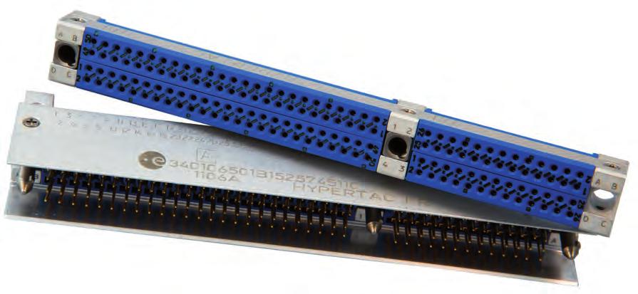
MHD Series. High Density Mixed Signal, Power and Coaxial Connectors. Technical Characteristics
 High ensity Mixed Signal, Power and Coaxial Connectors Ruggedized metal shell PCB connector, with shrouded plug for pin protection Signal and HE 80 cavities for power and coaxial contacts Male plug : Straight
HBB CONNECTOR SERIES
 HBB CONNECTOR SERIES High Power, Quick Release Connectors Hyperboloid Technology Smiths Connectors offers an extensive range of superior contact technologies suitable for standard and custom solutions.
KA Series. MIL-DTL Compliant PCB connectors
 MIL-DTL-55302 Compliant connectors Hypertac Hyperboloid Technology Smiths Interconnect offers an extensive range of superior contact technologies suitable for standard and custom solutions. Hypertac (HYPERboloid
HBB CONNECTOR SERIES. Engineering Superior Solutions. September 2015 Smiths Connectors. smithsconnectors.com
 HBB CONNECTOR SERIES Engineering Superior Solutions September 2015 Smiths Connectors HBB CONNECTOR SERIES High Power, Quick Release Connectors 2 Table of Contents 4 PRODUCT OVERVIEW 9 COMPETITIVE ADVANTAGES
EN3716 SAE AS81659 ARINC
 6 DSX RTX Series series SAE AS81659 EN3716 ARINC 404 Page Introduction... 6-4 Applications... 6-5 DSX SAE AS81659 Product overview... 6-6 Technical characteristics :... 6-7 & 6-8 Electrical... 6-7 Mechanical
REP Series. Environmentally-Sealed Rectangular Plastic Connectors
 Environmentally-Sealed Rectangular Plastic Connectors REP Series Environmentally - Sealed Rectangular Plastic Connectors Optimised for use in rail and embedded applications Smiths Interconnectors REP Series,
MMC RTX series EN3716
 MMC RTX series EN3716 7 CONTENTS Page Introduction... 7-4 Application 7-4 Features... 7-4 Product overview... 7-5 Electrical characteristics... 7-6 Mechanical & environmental characteristics... 7-6 Products
Monobloc Insulator Rectangular Connectors
 HYPERMOD NG series Monobloc Insulator Rectangular Connectors Compliant with DIN 43652 Up to 500 mating cycles Quadrax contacts grounding IP50 & IP66 sealing IDEAL FOR RAIL APPLICATIONS The HyperMod NG
I Non-magnetic D-Sub Connectors
 Non magnetic D-Sub Connectors Section I Non-magnetic D-Sub Connectors 5 Non magnetic D-Sub Contents Non magnetic D-Sub Connectors Cross reference table for ESA/SCC/SOURIAU/GSFC...7 Quality Assurance Testing...7
CONEC provides reliable and effective solutions to OEM, EMS and cable houses.
 CONEC CANADA USA CONEC designs and manufactures products in modern facilities. The products are made in accordance to the highest quality standards and industry specifications. CONEC provides reliable
SMB LOCK Introduction Characteristics Straight plugs Right angle plugs SMB limited detent (SMB-A) Receptacles...
 Receptacles...") CONTENTS PAGE SMB Introduction... 4 General... 5 Finder guide... 6 Interface... 7 Characteristics...8-9 Straight plugs...0- Right angle plugs...- Jacks... 3 Bulkhead jacks...4-5 Receptacles...6-7 PCB receptacles...
CONTENTS PAGE SMB Introduction... 4 General... 5 Finder guide... 6 Interface... 7 Characteristics...8-9 Straight plugs...0- Right angle plugs...- Jacks... 3 Bulkhead jacks...4-5 Receptacles...6-7 PCB receptacles...
MICRO-CONNECTOR CMM SERIES
 MICRO-CONNECTOR CMM SERIES CMM Series Micro-connectors NICOMATIC specializes in the design, development and manufacture of electronic connectors. The CMM MICRO CONNECTOR interconnection system is a 2mm
... A Vital Part of Connection World CMPTER. Cable Connectors PCB Connectors Assembly Instructions Mounting Holes MCX CONNECTORS
 ... A Vital Part of Connection World Cable Connectors PCB Connectors s Mounting Holes MCX CONNECTORS COPYRIGHT ELECTRONICS 0 MCX Series Coaxial Connectors DESCRIPTION MCX connector are developed in Europe
TE Connectivity DEUTSCH Single Module EN4165 connectors
 Applications Cabin and avionic systems High-performance military aircraft Commercial airlines Communications equipment Missiles Military Railway TE Connectivity DEUTSCH Single Module EN4165 Connectors
SMA CONTENTS PAGE 9-3
 CONTENTS PAGE SMA Introduction... 4 General... 5 Finder guide...6-7 Interface... 8 Characteristics...9-10 Straight plugs...11-12 Right angle plugs...13-14 Straight jacks... 14 Straight flange jacks...14-15
8STA/8TA Series. Compact Circular Connectors Derived from MIL-DTL & JN1003. Connection Technologies
 8STA/8TA Series Compact Circular Connectors Derived from MIL-DTL-38999 & JN1003 Connection Technologies 8STA/8TA Series Contents Overview Presentation... 06 Applications... 06 Features & benefits... 07
Our Most Important Connection is with You. SECTION 2 SMPM / SMP / SMP-LOCK / SMP-COM R201 / R222 / R222L / R2229
 SECTION 2 SMPM / SMP / SMP-LOCK / SMP-COM R201 / R222 / R222L / R2229 Contents SMPM Introduction... 2-4 Interface... 2-5 Characteristics... 2-6 Plugs and Jacks... 2-7 Receptacles and panel shrouds... 2-8
DEUTSCH HDJ Series Filter Connectors MIL-DTL SERIES I.5
 DEUTSCH HDJ Series connectors are subminiature environment-class connectors with high and medium-density insert arrangements. They are based on MIL-DTL-38999 Series I coupling interface lengths and Series
SERIES MHV (H4) HIGH VOLTAGE CONNECTORS
 HIGH VOLTAGE CONNECTORS") SERIES MHV (H4) HIGH VOLTAGE CONNECTORS DESCRIPTION CONTENTS PAGE HUBER+SUHNER MHV connectors are coaxial miniature high voltage (MHV = Miniature High Voltage) connectors with 5 kv rms test voltage (mated
SERIES MHV (H4) HIGH VOLTAGE CONNECTORS DESCRIPTION CONTENTS PAGE HUBER+SUHNER MHV connectors are coaxial miniature high voltage (MHV = Miniature High Voltage) connectors with 5 kv rms test voltage (mated
Interface Mating Dimensions
 SMP Coaxial Connectors SMP Coaxial Connectors SMP Connectors Interface SMPM Cable Connectors SV Microwave offers a complete line of SMP connectors that conform to DSCC 94007, 94008 and MIL-STD-348. The
SERIES BMA, SUBMINIATURE BLIND MATE CONNECTORS
 SERIES, SUBMINIATURE BLIND MATE CONNECTORS DESCRIPTION CONTENTS PAGE HUBER+SUHNER blind mate connectors open up special dimensions in microwave applications up to 18 GHz. HUBER+SUHNER offers a range of
RF COAXIAL CONNECTORS, TYPE SMA, 50 OHMS (FEMALE CONTACT) ESCC Detail Specification No. 3402/002
 ESCC Detail Specification No. 3402/002") Page 1 of 106 RF COAXIAL CONNECTORS, TYPE SMA, 50 OHMS (FEMALE CONTACT) ESCC Detail Specification Issue 5 June 2016 Document Custodian: European Space Agency see https://escies.org PAGE 2 LEGAL DISCLAIMER
Page 1 of 106 RF COAXIAL CONNECTORS, TYPE SMA, 50 OHMS (FEMALE CONTACT) ESCC Detail Specification Issue 5 June 2016 Document Custodian: European Space Agency see https://escies.org PAGE 2 LEGAL DISCLAIMER
SEK Solder board connectors
 Solder board connectors Technical characteristics 6, 10, 14, 16, 20, 26, 30*, 34, 40, 50, 60, 64 Contact arrangement straight, angled Contact length 2.9 mm, 4.5 mm Approvals IEC 603-13 DIN EN 60 603-13
RF COAXIAL CONNECTORS, TYPE SMA, 50 OHMS (MALE CONTACT) ESCC Detail Specification No. 3402/001
 ESCC Detail Specification No. 3402/001") Page 1 of 68 RF COAXIAL CONNECTORS, TYPE SMA, 50 OHMS (MALE CONTACT) ESCC Detail Specification Issue 3 January 2014 Document Custodian: European Space Agency see https://escies.org PAGE 2 LEGAL DISCLAIMER
Page 1 of 68 RF COAXIAL CONNECTORS, TYPE SMA, 50 OHMS (MALE CONTACT) ESCC Detail Specification Issue 3 January 2014 Document Custodian: European Space Agency see https://escies.org PAGE 2 LEGAL DISCLAIMER
SMB Amphenol. 50 ohm Coaxial Connectors Specifications 36 Plugs 37 Jacks 38 Bulkhead Receptacles PCB Receptacles 41-43
 Description The name derives from SubMiniature B (the second subminiature design). The was developed in the 1960 s. is a smaller version of the SMA with snap-on coupling. Amphenol s connectors conform
RECTANGULAR CONNECTORS PER ARINC 404 RM-RME SERIES
 Rev. C, March, 2016 RECTANGULAR CONNECTORS PER ARINC 404 RM-RME SERIES Connectors with wide range of shell configurations/modifications, contact arrangements and contacts to meet ARINC 404 Specification
Our Most Important Connection is with You. SECTION 17. Tooling & Accessories R280 / R282
 SECTION 17 Tooling & Accessories R280 / R282 Contents Joule effect soldering devices... 17-4 Stripping tools...17-4 and 17-7 Point gauges... 17-4 Soldering... 17-5 Installation tools...17-5 to 17-6 Cassettes...
Ethernet 100 Mbps Quadrax
 Ethernet 100 Mbps Quadrax Quadrax Contact Today s technology for Airbone and Military equipment is more and more complex, requiring the management of an increasing flow of information at greater speeds.
AMPLIMITE.050 Series Cable Assemblies, Series III
 Cable Assemblies, Series III To meet Standard Applications the following 106 ohm, black jacketed cable assemblies are available. For AMPLIMITE Series cable assemblies that meet other impedance requirements
Connectors and interconnect systems for severe environments
 Connectors and interconnect systems for severe environments The company designs, manufactures and markets high performance interconnect solutions for severe environments from industrial broadline and universal
POLAMCO HIGH POWER CONNECTORS STYLE
 POLAMCO HIGH POWER CONNECTORS 38999 STYLE Robust & reliable connectors designed for harsh environments Contents Part Description System... 4 Materials... 4 Plating Options... 5 SECTION ONE: Plugs 1.1 Shielded
SMC SERIES Subminiature Coaxial Connectors
 SERIES Subminiature Coaxial Connectors FEATURES Subminiature coaxial connectors with 50 Ω impedance for applications up to 0 GHz. (screw on mechanism)fulfills the subminiature coaxial connector requirement
FISCHER FREEDOM TM SERIES
 K CHAPTER FISCHER TM SERIES EASY MATING EASY CLEANING EASY INTEGRATION KEY FEATURES No key code: 360 mating freedom & optimized cable management Membrane-sealed contacts (patent pending) Low profile IP68
ARINC 600 SERIES. Rack & Panel Rectangular Connectors. High Density and Modularity
 ARINC 600 SERIES Rack & Panel Rectangular Connectors High Density and Modularity ARINC 600 Series RoHS VERSION Presentation Build the connector that matches exactly your requirements Modular Wide range
HPH PCB/MALE CABLE HPH SERIES PERFORMANCE/SPECIFICATION
 PCB/ CABLE Straight TBS, R/A TBS, male crimp, Flex SMT, solder bucket, stacking, pin carrier Pin size/current: 0.6mm/4 amp Pitch: 1.905mm/0.075" on a staggered pitch of 0.953mm/0.0375 No. of contacts:
ARINC 600 SERIES. Rack & Panel Rectangular Connectors. High Density and Modularity
 ARINC 600 SERIES Rack & Panel Rectangular Connectors High Density and Modularity ARINC 600 Series COMPLIANT Presentation BUILD THE CONNECTOR THAT MATCHES EXACTLY YOUR REQUIREMENTS Modular technology from
ARinc 600 Series. Rack & Panel Rectangular Connector. Brief introduction. Specification. 1. Material and surface treatment. 3. Electric properties
 ARinc 600 Series Rack & Panel Rectangular Connector Brief introduction Good performance of environment resistance 216 kinds of anti-misoperation styles High density up to 800 signal contacts Low insertion
Over-moldable Ruggedized Connectors for higher Amperage
 Over-moldable Ruggedized Connectors for higher Amperage Understanding Power and the need for interconnect solutions Power: Defined by the rate at which energy is used or generated. Electrical Power can
Temposonics. Magnetostrictive Linear Position Sensors. MHRM Analog Data Sheet. For embedded or externally threaded installation
 Temposonics ostrictive Linear Position Sensors MHRM Analog For embedded or externally threaded installation Sensor rod with Ø 7 mm or Ø 0 mm Resolution: ±0. mm typ. Compliant with EN 50-3- MEASURING TECHNOLOGY
MIL-DTL SERIES III CONNECTORS RUGGED, HARSH ENVIRONMENT SUBMINIATURE CONNECTORS
 QUICK REFERENCE GUIDE Wide Range Mil spec, commercial, and composite Full line of finishes, including black zinc nickel and PTFE nickel High Performance Environmentally sealed DEUTSCH MIL-DTL-38999 SERIES
Arinc 600 series. Contents. Discover Arinc 600. Range Overview. Technical Datas. Range Extension
 Contents Company Profile... 02 Applications... 04 Benefits... 05 Arinc Speed Service... 05 Product Overview... 06 Cavity Overview... 07 Inserts Layouts: Shell Size 1... 08 Shell Size 2 & 3... 08 Technical
SMPM. SMPM High Frequency Push-on. Module to Module (board to board) Misalignment. Application Notes SMPM
 Misalignment. Application Notes SMPM") 29 High Frequency Push-on Application Notes The connector, which is 30% smaller than its cousin, the, has similar features and applications. This is a multi-functional high frequency push-on connector
29 High Frequency Push-on Application Notes The connector, which is 30% smaller than its cousin, the, has similar features and applications. This is a multi-functional high frequency push-on connector
38999 Series III Composite Connectors
 8D Series Composite 38999 Series III Composite Connectors The RoHS connector with the best performance in weight saving and corrosion resistance for MilAero applications. MIL-DTL-38999 Standard Versatility
K CHAPTER FREEDOM TM SERIES EASY MATING EASY CLEANING EASY INTEGRATION FISCHER KEY FEATURES
 K CHAPTER FISCHER TM SERIES EASY MATING EASY CLEANING EASY INTEGRATION KEY FEATURES No key code: 360 mating freedom & optimized cable management Membrane-sealed contacts (patent pending) Low profile IP68
CONTENTS HMK SERIES X.100 CONNECTORS
 HMK SERIES CONTENTS HMK SERIES -.100 X.100 CONNECTORS PAGE 5 Introduction 6 Specifications 7 Ordering Chart - 2 & 3 Row 2 ROW UNINTERRUPTED (17-65 CONTACTS) 8 FC, FD, FS, FW, SC, SD, SS, SW- Socket, Straight
CHARACTERISTIC SPECIFICATION
 MICRO-D SERIES Microminiature connectors with solder bucket termination ESCC 3401/029 Features and Benefits Compliant with ESA specifications High performance Micropin contact system ( twist pin spring
Wedge in Plugs Stock No
 Amphenol Connectors Description Plugs Stock No. Receptacles Stock No. 2-way 38170 38171 3-way 38172 38173 4-way 38174 38175 6-way 38176 38177 8-way 38178 38179 12-way 38180 38181 Wedge in Plugs Stock No.
MILITARY MOTORSPORT INDUSTRIAL PRODUCT RANGE
 MILITARY MOTORSPORT INDUSTRIAL PRODUCT RANGE ABOUT US VGL Impex Pty Ltd, trading as Allied Connectors, is an Australian based distributor of industrial electrical components and complementary products.
HARTING. Interface Connectors. People Power Partnership
 11 4 HARTING Interface Connectors People Power Partnership People Power Partnership Quality Connections Worldwide HARTING was founded in 1945 by the family that still owns the company. Today, HARTING employs
D-Sub Connectors. Catalog E /09 Edition 3
 www.erni.com Catalog E 074573 11/09 Edition 3 www.erni.com www.erni.com Catalog E 074573 11/09 Edition 3 www.erni.com Table of Contents General..............................................................................................2
Interface Mating Dimensions
 SMPM Coaxial Connectors SMPM Connectors DC - 65 GHz SV Microwave offers a complete line of SMPM connectors. SMPM connectors, a push-on mating design, provide microwave performance through 65 GHz and offer
Doc-8Pages-DER-2:Application Internal 9/09/08 16:28 Page 1 HIGH RELIABILITY CONNECTORS FOR RAILWAY APPLICATIONS
 Doc-8Pages-DER-2:Application Internal 9/09/08 16:28 Page 1 HIGH RELIABILITY CONNECTORS FOR RAILWAY APPLICATIONS Doc-8Pages-DER-2:Application Internal 9/09/08 16:29 Page 2 HYPERTAC CONNECTORS A WORLD LEADING
 Distributed by: www.jameco.com 1-800-831-4242 The content and copyrights of the attached material are the property of its owner. Connectors Features Snap-on interface facilitates assembly Conforms to CECC
Microminiature Connectors
 Microminiature Connectors Product Manager August 2013 The Microminiature Range 3 basic families of small pitch connectors CENTI Line - 0.075" / 1.90mm pitch between contacts 2D double density, CTA strip,
HBB power connector. Product description
 HBB power connector Product description Contact technology guarantees high reliability Push lock to mate connector Quick release latch to unmate Ruggedised metal and plastic versions available Cable and
Multi-Pole Rectangular Connectors Specifications Table
 Multi-Pole Rectangular Connectors Specifications Table Multi-Pole Rectangular Connectors Specifications Table Number of Poles Rating Insulation Resistance Dielectric Strength Contact Resistance Insertion
Modular Bayonet connectors: a flexible solution for data and signals transmission in railways harsh environment.
 GM Modular Bayonet connectors: a flexible solution for data and signals transmission in railways harsh environment. Passenger control Networking and lighting control Diagnostic support for brakes, motors
BLINDMATE CONNECTORS AND COMPONENTS. Selection Guide BMA BMMA BMZ BZ
 BLINDMATE CONNECTORS AND COMPONENTS SV Microwave, Inc. is a world leader in the RF/microwave industry. We design and manufacture coaxial connectors, cable assemblies, attenuators, terminations, and custom
Amphenol-Tuchel Electronics 44 Series
 44 Series Amphenol-Tuchel Electronics 44 Series Cost-effective environmental sealing Amphenol Tuchel 44 series connectors offer cost-effective performance for applications requiring environmental sealing.
MD CONNECTOR. 1Certified LR Miniature circular connectors. Standards
 Miniature circular connectors Standards 0 Recognized E09 Certified LR0 Shielding effect Shielding effect(db) 0 0 0 Braided wires soldered to the metal shell 0 0 0 0 0 90 MD connector(with ground clip)
Ultra Miniature Snap-on Coaxial Connector (PC Card Type 2 Mountable)
") Ultra Miniature Snap-on Coaxial Connector (PC Card Type 2 Mountable) MMCX Series Right-angle Receptacle Features 1. Snap-on coupling mechanism makes it easy to engage and disengage. The rugged snap-on
Ultra Miniature Snap-on Coaxial Connector (PC Card Type 2 Mountable) MMCX Series Right-angle Receptacle Features 1. Snap-on coupling mechanism makes it easy to engage and disengage. The rugged snap-on
MIL-DTL Series 1 Solder Type PT
 MIL-DTL-26482 Series 1 Solder Type PT The Amphenol Miniature Cylindrical Connector Series offers high density contact arrangements in a miniature, circular metal shell. This connector is environmentally
ARINC 600 SERIES. Rack & Panel Rectangular Connectors. Selector Guide
 ARIN 600 ERIE Rack & Panel Rectangular onnectors elector Guide ARIN 600 eries Overview Typical applications ockpit Display Units Mario Beauregard / Fotolia ourtesy of NORD-MIRO Picture All Rights Reserved
HERMETIC. Hermetic Connectors. High Performance Sealing Solutions
 HERMETIC Hermetic Connectors High Performance Sealing Solutions Hermetic Connectors 38999 QPL Qualified Presentation Based on glass to metal seal technology, SOURIAU offers hermetic connectors to cover
D-SUB Series. Electrical Max current rating per contact : 7.5 A. Insulation resistance : 5000 MΩ Contact resistance : 10 mω
 -SU Series pplications For military and aerospace applications. s MiL- 24308 HE 501 HE 508 HE 507 haracteristics Mechanical Shell : cadmium plated steel Insulator : monothermoset and two parts thermoplastics
Quick Reference Guide AMP CT Connector Series
 Quick Reference Guide The AMP CT connectors are a miniature wire-to-board and wire-to-wire interconnect solution. The AMP CT connector series has proven performance in its harness making capability. A
06. har-mik INTERFACE CONNECTORS
 . INTERFACE CONNECTORS Miniature D connectors are a must in various cableto-board applications where space saving and high data transfer rates are required. For the purposes of miniaturization and speed,
SMB Connectors Specifications Flexible Cable Bulkhead PCB Mount... 66
 Section Index Connectors Specifications... 62 Flexible Cable... 64 Bulkhead... 65 PCB Mount... 66 Other Information Assembly Instructions... 176 Cable Assembly... 166 Cable Information... 168 Numerical
Connectors Type M DIN / IEC Catalog E /01 Edition 1
 Connectors Type M DIN 41612 / IEC 60603-2 www.erni.com www.erni.com Contents General Information 3 Electrical & Mechanical Specifications for Connectors 4 Standard Male Connectors for Daughtercards 6 Standard
Push-Pull connectors
 Push-Pull connectors Introduction This catalog presents the push-pull connectors ranges for industrial applications. These products are particularly suitable for high reliability and high quality applications
Amphenol. eries SJT. Series SJT. VG 96912, Series 1 PAN JN 1003
 Amphenol eries SJT Series SJT VG 96912, Series 1 PAN 6433-2 JN 1003 Ordering information Ordering example: SJT G 06 RT 14-35 P A 014 Series (p. 9, 15, 18) SJT Scoop proof (100% scoop-proof) Junior (Miniature
CMC/CPP/CMB SERIES. Power & signal connectors with screw locking system. Human photo. Can be environmental/ documentaty style or portrait of engineer.
 Human photo. Can be environmental/ documentaty style or portrait of engineer. CMC/CPP/CMB SERIES Power & signal connectors with screw locking system CMC/CPP/CMB SERIES /// POWER & SIGNAL CONNECTORS Contents
1Rack and Panel Connectors
 Rack and Panel Connectors Table of Contents RINC 600 Connectors Introduction............................................................2 Ordering Information.....................................................3
Cannon Mil-DTL Class G Space Grade Connectors. Interconnect Solutions
 Cannon Mil-DTL 38999 Class G Space Grade Connectors Interconnect Solutions The Challenge Our traditional and longest served Space System customers approached ITT ICS regarding the deployment of Mil-DTL
8LT SERIES. Aerospace & Military Bayonet Connectors. MIL-DTL Series I
 8LT SERIES Aerospace & Military Bayonet Connectors Contents Overview 8LT Series Presentation... 06 8LT Series Applications... 06 A universal product platform... 07 Contact layouts... 08 Contact layouts
MicroMate (MMCX) Amphenol Specifications
 Amphenol Specifications") Specifications ELECTRICAL CECC22000 Test Requirement Impedance 50 Ohm Frequency Range DC thru 6 GHz VSWR 4.4.1 SMT and Edgecard (Mated Pair) DC - 4 GHz 1.15 Max 4-6 GHz 1.40 Max Cabled Straight, Semi-Rigid
Specifications ELECTRICAL CECC22000 Test Requirement Impedance 50 Ohm Frequency Range DC thru 6 GHz VSWR 4.4.1 SMT and Edgecard (Mated Pair) DC - 4 GHz 1.15 Max 4-6 GHz 1.40 Max Cabled Straight, Semi-Rigid
More Precision. mainsensor Magneto-inductive displacement sensor
 More Precision mainsensor Magneto-inductive displacement sensor mainsensor Magneto-inductive sensors for non-contact linear displacement measurement Measuring principle mainsensor is based on an innovative
Modular Bayonet connectors: a flexible solution for data and signals transmission in railways harsh environment.
 GM Modular Bayonet connectors: a flexible solution for data and signals transmission in railways harsh environment. Passenger control Networking and lighting control Diagnostic support for brakes, motors
microcomp SERIES Miniature Lightweight High Density Connectors Space Grade - ESA QPL
 microcomp SERIES Miniature Lightweight High Density Connectors Space Grade - ESA QPL Space Grade microcomp Contents Overview... 4 Features and benefits... 6 Comparison with micro-d... 7 Comparison with
HYPERBOLOID CONNECTORS
 HMM.075 x.075 HYPERBOLOID SERIES HYPERBOLOID CONNECTORS FOR SUPERIOR PERFORMANCE IN ALL APPLICATIONS IEH CORPORATION O ISO 9001:2000 SMALL BUSINESS-HUB-ZONE CERTIFIED www.iehcorp.com HMM SERIES CONTENTS
Table of Contents SMA CONNECTORS
 Table of Contents 45 SMA Connectors 3 MMCX Connectors 50 Ohm Connectors Specifications...46 Quick Connect...49 Semi-Rigid & Flexible Cable...50 PC Mount...56 Bulkhead & Panel Mount...62 Self-Fixture End
Single 2 Piece Contacts: BTB
 Dissecting linear LED lighting from a connector standpoint looks very simple from far away, but up close there is no magical solution. Even though there have been new connectors developed in recent years
microcomp SERIES Miniature Lightweight High Density Connectors
 microcomp SERIES Miniature Lightweight High Density Connectors Contents Overview... 4 Features and benefits...5-6 Comparison with high density D-Sub... 7 Comparison with micro-d... 8 Technical Features...
D-Subminiature EMI/RFI Shielding Interconnection Systems
 Amphenol Amphenol PCD Shenzhen D-Subminiature EMI/RFI Shielding Interconnection Systems www.amphenolpcd.com.cn Product profile RR-HR D-Sub connectors - stamped and formed contacts REAR RELEASE CRIMP CONNECTORS
Luminus Series Amphenol Pcd
 Luminus Series Amphenol Pcd Amphenol Pcd Pcd is is one one of of the the world s leading suppliers of of interconnect products for for Military, Commercial Aerospace and and Industrial applications. Located
MIL-DTL Series III Connectors
 RELIABLE Self-locking threaded coupling 100% scoop proof Contact retention system provides excellent contact retention under severe vibration EMI PROTECTED Grounding fingers for excellent EMI protection
for Quadrax and ELIO 8
 1 - CHARACTERISTICS Mechanical Current ratings, continuous: Endurance: 500 matings Insertion and extraction forces, max: - shell size 1: 120 N (27 Ibs) - shell size 2: 267 N (60 Ibs) - shell size 3: 467
CMC Hybrid Connectors Standard and Power Versions
 CMC hybrid connectors and mating headers provide sealed, high-density, modular and cost-effective wire-to-board and wire-to-wire connection systems for heavy-duty powertrain and body-electronics applications
RoHS 2011/65/EU ISO 9001 ISO BS OHSAS 18001:2007 GREEN ELECTRONICS CCF. Connectors
 RoHS 2011/65/EU e3 GREEN ELECTRONICS ISO 9001 ISO 14001 BS OHSAS 18001:2007 Connectors Functional characteristics Dimensional class: medium RoHS 2011/65/EU Standard colour: green Dimensions: 25.4 x 14.9
MICRO-D SERIES. Microminiature connectors with solder bucket termination CS FR022. Features and Benefits. Typical Applications
 MICRO-D SERIES Microminiature connectors with solder bucket termination CS FR022 Features and Benefits High performance Micropin contact system ( twist pin spring male contact and tubular socket contact)
SRC SERIES. Signal Connectors with bayonet locking system. Derived from VG95234 & in accordance with the NF F standard
 SERIES Signal Connectors with bayonet locking system Derived from VG9523 & in accordance with the NF F 61-030 standard SERIES /// SIGNAL CONNECTORS Contents Main Characteristics... 2 Synoptic...3- Synoptic:
Connection Systems. Bulls-Eye Subminiature Circular Connectors
 Connection Systems Bulls-Eye Subminiature Circular Connectors Connection Systems Bulls-Eye Subminiature Circular Connectors Hit the target every time with our high density connectors that provide high
Through Hole Connectors
 Through Hole Connectors 43 Whether your Through-Hole Technology applications require a Quick Disconnect Tab, an Insulation Displacement Connector, a Test Point Terminal, a Screw Terminal, a Receptacle,
Directory chapter 08. InduCom Robust and EMI protected D-Sub interfaces
 Directory chapter 08 Robust and EMI protected D-Sub interfaces New Page General information.............................................. 08.02 Mounting details................................................
about us In 2011, Switchcraft was acquired by HEICO Corporation and became part of their Electronic Technologies Group.
 table of contents 2 about us 3 custom products circular connectors & cable assemblies 6 en2 0.53 [13mm] od - 2-7 contacts 10 micro-con-x 0.53 [13mm] od - 2-7 contacts 16 en3 0.71 [18mm] od - 2-18 contacts
92-Position LGA/LGA PCBeam Connector for
 92-Position LGA/LGA PCBeam Connector for Neoconix P/N: BBX0092CMMHFAU00 FEATURES High density 0.7424mm area-array pitch Low profile, 1.55 mm mated height PCBeam high reliability LGA spring contacts Bifurcated
8T Series. MIL-DTL Series II
 Contents Overview 8T Series - Presentation... 06 8T Series - Applications... 06 A universal product platform... 07 Space saving... 08 ox solutions... 08 Shell types... 08 Features by shell types... 09
SCE. Snatch Connector Electrical Series
 SCE Snatch Connector Electrical Series SCE is a miniature product with a silent push to mate and pull to release design across two styles of cable receptacles. All inserts and contacts are moulded in place,
fischer ultralight connectors AluLite series new Edition 1.0
 fischer ultralight connectors AluLite series new Edition.0 fischer ultralight connectors New AluLite series When weight matters Are weight considerations significant in the design and development of your