TEXAS TRANSPORTATION INSTITUTE THE TEXAS A & M UNIVERSITY SYSTEM COLLEGE STATION, TEXAS 77843
|
|
|
- Carol Teresa Richardson
- 5 years ago
- Views:
Transcription
1 NCHRP REPORT 350 ASSESSMENT OF EXISTING ROADSIDE SAFETY HARDWARE by C. Eugene Buth, P.E. Senior Research Engineer Wanda L. Menges Associate Research Specialist and Sandra K. Schoeneman Research Associate Contract No. DTFH61-97-C Project No F Sponsored by U.S. Department of Transportation Federal Highway Administration November 2000 TEXAS TRANSPORTATION INSTITUTE THE TEXAS A & M UNIVERSITY SYSTEM COLLEGE STATION, TEXAS 77843
2
3 1. Report No. FHWA-RD Technical Report Documentation Page 2. Government Accession No. 3. Recipient's Catalog No. 4. Title and Subtitle NCHRP REPORT 350 ASSESSMENT OF EXISTING ROADSIDE SAFETY HARDWARE 5. Report Date 6. Performing Organization Code 7. Author(s) C. Eugene Buth, Wanda L. Menges, and Sandra K. Schoeneman 9. Performing Organization Name and Address Texas Transportation Institute The Texas A&M University System College Station, Texas Sponsoring Agency Name and Address Office of Safety and Traffic Operations Research and Development Federal Highway Administration 6300 Georgetown Pike McLean, VA Performing Organization Report No F 10. Work Unit No. (TRAIS) 11. Contract or Grant No. DTFH61-97-C Type of Report and Period Covered Final Report July August Sponsoring Agency Code 15. Supplementary Notes Research Study Title: Assessment of Existing Roadside Safety Hardware - II Contracting Officer s Technical Representative (COTR): Charles F. McDevitt - HRDS Abstract The Federal Highway Administration initiated this contract with the objective to crash test and evaluate several terminals, transitions, and longitudinal barriers to NCHRP Report 350. NCHRP Report 350 specifies crash tests and evaluation criteria for three performance levels for terminals and six performance levels for transitions and longitudinal barriers. The buried-in-backslope terminals evaluated were the G4 on steel posts and wood blockouts with a rub rail and a 6 to 1 vee ditch and the G4 with steel posts and wood blockouts with a 4 to 1 slope. Both met specifications for NCHRP Report 350 test The 3-strand New York cable terminal was evaluated and met requirements for NCHRP Report 350 test The transitions evaluated under this contract included the vertical wall transition (W-beam with W-beam rub rail and steel posts), the vertical flared back transition (W-beam with channel rub rail, steel posts, and routed wood blockouts), the Pennsylvania Department of Transportation (DOT) transition (vertical flared back concrete parapet with W-beam, rub rail, steel posts, and routed wood blockouts), the Nebraska thrie beam transition (vertical wall parapet with thrie beam), and the Connecticut W-beam transition (NJ-shape wall with W-beam and channel rub rail). All the transitions met the required criteria for NCHRP Report 350 test 3-21, except for the vertical flared back transition. The MB1 median cable barrier chosen for evaluation was the Washington State DOT (WSDOT) cable barrier with a New York cable rail terminal. The thrie beam guardrail with steel posts and routed wood blockouts and the strong wood post thrie beam guardrail were also evaluated. The cable barrier and both thrie beam guardrails met the required specifications for NCHRP Report 350 test The modified thrie beam guardrail with 2.1-m-long W150x14 steel posts and W360x33 blockouts (Design No. SGR09b) was evaluated and met specifications for NCHRP Report 350 test Construction details for all the terminals, transitions, and longitudinal barriers evaluated are reported herein. Also included are details of the crash tests performed and the assessment of each test. 17. Key Words Terminals, transitions, longitudinal barriers, cable barriers, guardrails, crash testing, roadside safety 18. Distribution Statement No restrictions. This document is available to the public through the National Technical Information Service, 5285 Port Royal Road, Springfield, Virginia Security Classif. (of this report) Unclassified 20. Security Classif. (of this page) Unclassified 21. No. of Pages Price Form DOT F (8-72) Reproduction of completed page authorized
4 SI* (MODERN METRIC) CONVERSION FACTORS APPROXIMATE CONVERSIONS TO SI UNITS APPROXIMATE CONVERSIONS FROM SI UNITS Symbol When You Know Multiply by To Find Symbol Symbol When You Know Multiply by To Find Symbol LENGTH LENGTH in ft yd mi inches feet yards miles millimeters meters meters kilometers mm m m km mm m m km millimeters meters meters kilometers inches feet yards miles in ft yd mi AREA AREA in 2 ft 2 yd 2 ac mi 2 square inches square feet square yards acres square miles square millimeters mm 2 square meters m 2 square meters m 2 hectares ha square kilometers km 2 mm 2 m 2 m 2 ha km 2 square millimeters square meters square meters hectares square kilometers square inches square feet square yards acres square miles in 2 ft 2 yd 2 ac mi 2 VOLUME VOLUME fl oz gal ft 3 yd 3 fluid ounces gallons cubic feet cubic yards milliliters liters cubic meters cubic meters ml L m 3 m 3 ml L m 3 m 3 milliliters liters cubic meters cubic meters fluid ounces gallons cubic feet cubic yards fl oz gal ft 3 yd 3 ii NOTE: Volumes greater than 1000 l shall be shown in m 3. MASS MASS oz lb T ounces pounds short tons (2000 lb) grams kilograms megagrams (or metric ton ) g kg Mg (or t ) g kg Mg (or t ) grams kilograms megagrams (or metric ton ) ounces pounds short tons (2000 lb) oz lb T TEMPERATURE (exact) TEMPERATURE (exact) EF Fahrenheit temperature 5(F-32)/9 or (F-32)/1.8 Celcius temperature EC EC Celcius temperature 1.8C+32 Fahrenheit temperature EF ILLUMINATION ILLUMINATION fc fl foot-candles foot-lamberts lux candela/m 2 lx cd/m 2 lx cd/m 2 lux candela/m foot-candles foot-lamberts fc fl FORCE and PRESSURE or STRESS FORCE and PRESSURE or STRESS lbf lbf/in 2 poundforce 4.45 poundforce per square 6.89 inch newtons kilopascals N kpa N kpa newtons kilopascals poundforce lbf poundforce per square lbf/in inch 2 *SI is the symbol for the International System of Units. Appropriate (Revised September 1993) rounding should be made to comply with Section 4 of ASTM E380.
5 TABLE OF CONTENTS Section Page INTRODUCTION...1 PROBLEM...1 BACKGROUND...1 OBJECTIVES/SCOPE OF RESEARCH...1 TEST PARAMETERS...3 TEST FACILITY...3 TEST ARTICLES...3 TEST CONDITIONS...3 EVALUATION CRITERIA...3 TERMINALS...5 BURIED-IN-BACKSLOPE TERMINAL (WITH 6 to 1 VEE DITCH) (NCHRP REPORT 350 TEST NO. 3-35)...5 Test Conditions...5 Test Article...5 Soil and Weather Conditions...9 Test Vehicle...9 Impact Description...9 Damage to Test Article...12 Vehicle Damage...12 Occupant Risk Factors...12 Assessment of Test Results...12 BURIED-IN-BACKSLOPE TERMINAL (WITH 4 to 1 SLOPE) (NCHRP REPORT 350 TEST NO. 3-35)...19 Test Conditions...19 Test Article...19 Soil and Weather Conditions...24 Test Vehicle...24 Impact Description...24 Damage to Test Article...24 Vehicle Damage...27 Occupant Risk Factors...27 Assessment of Test Results...27 iii
6 TABLE OF CONTENTS (continued) Section Page NEW YORK TERMINAL FOR 3-CABLE BARRIER (NCHRP REPORT 350 TEST NO. 3-34)...33 Test Conditions...33 Test Article...33 Soil and Weather Conditions...37 Test Vehicle...37 Impact Description...37 Damage to Test Article...37 Vehicle Damage...40 Occupant Risk Factors...40 Assessment of Test Results...40 TRANSITIONS...45 VERTICAL WALL TRANSITION TEST 2 (NCHRP REPORT 350 TEST NO. 3-21)...45 Test Conditions...45 Test Article...45 Soil and Weather Conditions...48 Test Vehicle...48 Impact Description...51 Damage to Test Article...51 Vehicle Damage...51 Occupant Risk Factors...54 Assessment of Test Results...54 VERTICAL WALL TRANSITION TEST 12 (NCHRP REPORT 350 TEST NO. 3-21)...58 Test Conditions...58 Test Article...58 Soil and Weather Conditions...58 Test Vehicle...58 Impact Description...61 Damage to Test Article...61 Vehicle Damage...61 Occupant Risk Factors...61 Assessment of Test Results...65 iv
7 TABLE OF CONTENTS (continued) Section Page VERTICAL FLARED BACK TRANSITION (NCHRP REPORT 350 TEST NO. 3-21)...68 Test Conditions...68 Test Article...68 Soil and Weather Conditions...73 Test Vehicle...73 Impact Description...73 Damage to Test Article...73 Vehicle Damage...76 Occupant Risk Factors...76 Assessment of Test Results...76 PENNSYLVANIA TRANSITION (NCHRP REPORT 350 TEST NO. 3-21)...81 Test Conditions...81 Test Article...81 Soil and Weather Conditions...88 Test Vehicle...88 Impact Description...88 Damage to Test Article...90 Vehicle Damage...90 Occupant Risk Factors...90 Assessment of Test Results...90 NEBRASKA TRANSITION (NCHRP REPORT 350 TEST NO. 3-21)...97 Test Conditions...97 Test Article...97 Soil and Weather Conditions Test Vehicle Impact Description Damage to Test Article Vehicle Damage Occupant Risk Factors Assessment of Test Results v
8 TABLE OF CONTENTS (continued) Section Page CONNECTICUT TRANSITION (NCHRP REPORT 350 TEST NO. 3-21) Test Conditions Test Article Soil and Weather Conditions Test Vehicle Impact Description Damage to Test Article Vehicle Damage Occupant Risk Factors Assessment of Test Results LONGITUDINAL BARRIERS MB1 (WSDOT) MEDIAN CABLE BARRIER (NCHRP REPORT 350 TEST NO. 3-11) Test Conditions Test Article Soil and Weather Conditions Test Vehicle Impact Description Damage to Test Article Vehicle Damage Occupant Risk Factors Assessment of Test Results THRIE BEAM GUARDRAIL (STEEL POSTS AND ROUTED WOOD BLOCKOUTS) (NCHRP REPORT 350 TEST NO. 3-11) Test Conditions Test Article Soil and Weather Conditions Test Vehicle Impact Description Damage to Test Article Vehicle Damage Occupant Risk Factors Assessment of Test Results vi
9 TABLE OF CONTENTS (continued) Section Page THRIE BEAM ON STRONG WOOD POSTS (NCHRP REPORT 350 TEST NO. 3-11) Test Conditions Test Article Soil and Weather Conditions Test Vehicle Impact Description Damage to Test Article Vehicle Damage Occupant Risk Factors Assessment of Test Results MODIFIED THRIE BEAM GUARDRAIL (NCHRP REPORT 350 TEST NO. 4-12) Test Conditions Test Article Soil and Weather Conditions Test Vehicle Impact Description Damage to Test Article Vehicle Damage Occupant Risk Factors Assessment of Test Results SUMMARY AND CONCLUSIONS TERMINALS Buried-in-Backslope Terminal (with 6 to 1 vee ditch) Buried-in-Backslope Terminal (with 4 to 1 slope) New York Terminal for 3-Cable Barrier TRANSITIONS Vertical Wall Transition Vertical Flared Back Transition Pennsylvania Transition Nebraska Transition Connecticut Transition vii
10 TABLE OF CONTENTS (continued) Section Page LONGITUDINAL BARRIERS MB1 (WSDOT) Median Cable Barrier Thrie Beam Guardrail (with steel posts and routed wood blockouts) Thrie Beam on Strong Wood Posts Modified Thrie Beam Guardrail REFERENCE APPENDIX A: CRASH TEST PROCEDURES APPENDIX B: TEST VEHICLES APPENDIX C: SEQUENTIAL PHOTOGRAPHS APPENDIX D: VEHICULAR ANGULAR DISPLACEMENTS APPENDIX E: VEHICLE ACCELEROMETER TRACES viii
11 LIST OF FIGURES Figure Page 1 Details of the G4 W-beam guardrail buried-in-backslope terminal installation for test G4 W-beam guardrail backslope anchor terminal installation prior to test Vehicle before test G4 W-beam guardrail buried-in-backslope terminal after test Vehicle after test Summary of results for the Buried-in-Backslope Terminal (with 6 to 1 vee ditch) test, NCHRP Report 350 test Details of the G4 W-beam guardrail buried-in-backslope terminal installation for test G4 W-beam guardrail buried-in-backslope installation prior to test Vehicle before test Installation after test Vehicle after test Summary of results for the Buried-in-Backslope Terminal (with 4 to 1 vee ditch) test, NCHRP Report 350 test Details of the New York cable rail terminal installation for test New York cable rail terminal installation prior to test Vehicle before test New York cable rail terminal after test Vehicle after test Summary of results for the New York terminal test, NCHRP Report 350 test Details of the vertical wall transition installation for test Vertical wall transition prior to test Vehicle before test Installation after test Vehicle after test Summary of results for the first test on the vertical wall transition, NCHRP Report 350 test Vertical wall transition prior to test Vehicle before test Installation after test Vehicle after test Summary of results for the repeat test on the vertical wall transition, NCHRP Report 350 test Details of the vertical flared back transition installation for test Vertical flared back transition prior to test ix
12 LIST OF FIGURES (continued) Figure Page 32 Vehicle before test Installation after test Vehicle after test Summary of results for the Vertical Flared Back Transition test, NCHRP Report 350 test Details of the Pennsylvania transition installation for test Pennsylvania transition prior to test Vehicle before test Installation after test Vehicle after test Summary of results for the Pennsylvania transition test, NCHRP Report 350 test Details of the Nebraska thrie beam transition installation for test Nebraska thrie beam transition prior to test Vehicle before test Installation after test Vehicle after test Summary of results for Nebraska Transition test, NCHRP Report 350 test Details of the Connecticut transition installation for test Connecticut transition prior to test Vehicle before test Installation after test Vehicle after test Summary of results for the Connecticut Transition test, NCHRP Report 350 test Details of the Washington 3-strand cable barrier for test Details of the New York cable terminal used for test Washington 3-strand cable barrier with New York terminal prior to test Vehicle before test Installation after test Vehicle after test Summary of results for WSDOT Cable Barrier test, NCHRP Report 350 test Details of the thrie beam guardrail with 2.1-m steel posts and wood blockouts installation for test Thrie beam guardrail installation prior to test Vehicle before test x
13 LIST OF FIGURES (continued) Figure Page 64 Installation after test Vehicle after test Summary of results for the Thrie Beam Guardrail (steel posts/wood blockouts) test, NCHRP Report 350 test Details of the strong wood post thrie beam guardrail installation for test Strong wood post thrie beam guardrail installation prior to test Vehicle before test Installation after test Vehicle after test Summary of results for the Thrie Beam Guardrail on Strong Wood Posts, NCHRP Report 350 test Details of the modified thrie beam guardrail installation for test Modified thrie beam guardrail installation prior to test Vehicle before test Installation after test Vehicle after test Summary of results for test , NCHRP Report 350 test Vehicle properties for test Vehicle properties for test Vehicle properties for test Vehicle properties for test Vehicle properties for test Vehicle properties for test Vehicle properties for test Vehicle properties for test Vehicle properties for test Vehicle properties for test Vehicle properties for test Vehicle properties for test Vehicle properties for test Sequential photographs for test (overhead and frontal views) Sequential photographs for test (rear view) Sequential photographs for test (overhead and frontal views) Sequential photographs for test (rear view) xi
14 LIST OF FIGURES (continued) Figure Page 96 Sequential photographs for test (overhead and frontal views) Sequential photographs for test (oblique view) Sequential photographs for test (overhead and frontal views) Sequential photographs for test (rear views) Sequential photographs for test (overhead and frontal views) Sequential photographs for test (rear views) Sequential photographs for test (overhead and frontal views) Sequential photographs for test (rear view) Sequential photographs for test (overhead and frontal views) Sequential photographs for test (rear view) Sequential photographs for test (overhead and frontal views) Sequential photographs for test (rear view) Sequential photographs for test (overhead and frontal views) Sequential photographs for test (rear view) Sequential photographs for test (overhead and frontal views) Sequential photographs for test (rear views) Sequential photographs for test (overhead and frontal views) Sequential photographs for test (rear view) Sequential photographs for test (overhead and frontal views) xii
15 LIST OF FIGURES (continued) Figure Page 115 Sequential photographs for test (rear view) Sequential photographs for test (overhead and frontal views) Sequential photographs for test (rear view) Vehicular angular displacements for test Vehicular angular displacements for test Vehicular angular displacements for test Vehicular angular displacements for test Vehicular angular displacements for test Vehicular angular displacements for test Vehicular angular displacements for test Vehicular angular displacements for test Vehicular angular displacements for test Vehicular angular displacements for test Vehicular angular displacements for test Vehicle angular displacements for test Vehicle angular displacements for test Vehicle longitudinal accelerometer trace for test (accelerometer located at center of gravity) Vehicle lateral accelerometer traces for test (accelerometer located at center of gravity) Vehicle vertical accelerometer trace for test (accelerometer located at center of gravity) Vehicle longitudinal accelerometer trace for test (accelerometer located over rear axle) Vehicle lateral accelerometer traces for test (accelerometer located over rear axle) Vehicle vertical accelerometer trace for test (accelerometer located over rear axle) Vehicle longitudinal accelerometer trace for test (accelerometer located on top surface of instrument panel) Vehicle longitudinal accelerometer trace for test (accelerometer located on right front brake caliper) Vehicle lateral accelerometer trace for test (accelerometer located on left front brake caliper) Vehicle longitudinal accelerometer trace for test (accelerometer located on top of engine block) xiii
16 LIST OF FIGURES (continued) Figure Page 141 Vehicle longitudinal accelerometer trace for test (accelerometer located on bottom of engine block) Vehicle longitudinal accelerometer trace for test (accelerometer located at center of gravity) Vehicle lateral accelerometer trace for test (accelerometer located at center of gravity) Vehicle vertical accelerometer trace for test (accelerometer located at center of gravity) Vehicle longitudinal accelerometer trace for test (accelerometer located over rear axle) Vehicle lateral accelerometer trace for test (accelerometer located over rear axle) Vehicle vertical accelerometer trace for test (accelerometer located over rear axle) Vehicle longitudinal accelerometer trace for test (accelerometer located at center of gravity) Vehicle lateral accelerometer trace for test (accelerometer located at center of gravity) Vehicle vertical accelerometer trace for test (accelerometer located at center of gravity) Vehicle longitudinal accelerometer trace for test (accelerometer located over rear axle) Vehicle lateral accelerometer trace for test (accelerometer located over rear axle) Vehicle longitudinal accelerometer trace for test (accelerometer located on top surface of instrument panel) Vehicle longitudinal accelerometer trace for test (accelerometer located on right front brake caliper) Vehicle longitudinal accelerometer trace for test (accelerometer located on left front brake caliper) Vehicle longitudinal accelerometer trace for test (accelerometer located on top of engine block) Vehicle longitudinal accelerometer trace for test (accelerometer located on bottom of engine block) Vehicle longitudinal accelerometer trace for test (accelerometer located at center of gravity) Vehicle lateral accelerometer traces for test (accelerometer located at center of gravity) xiv
17 LIST OF FIGURES (continued) Figure Page 160 Vehicle vertical accelerometer trace for test (accelerometer located at center of gravity) Vehicle longitudinal accelerometer trace for test (accelerometer located over rear axle) Vehicle lateral accelerometer traces for test (accelerometer located over rear axle) Vehicle vertical accelerometer trace for test (accelerometer located over rear axle) Vehicle longitudinal accelerometer trace for test (accelerometer located on top surface of instrument panel) Vehicle lateral accelerometer traces for test (accelerometer located on right front brake caliper) Vehicle longitudinal accelerometer trace for test (accelerometer located on left front brake caliper) Vehicle longitudinal accelerometer trace for test (accelerometer located on top of engine block) Vehicle longitudinal accelerometer trace for test (accelerometer located on bottom of engine block) Vehicle longitudinal accelerometer trace for test (accelerometer located at center of gravity) Vehicle lateral accelerometer trace for test (accelerometer located at center of gravity) Vehicle vertical accelerometer trace for test (accelerometer located at center of gravity) Vehicle longitudinal accelerometer trace for test (accelerometer located over rear axle) Vehicle lateral accelerometer trace for test (accelerometer located over rear axle) Vehicle vertical accelerometer trace for test (accelerometer located over rear axle) Vehicle longitudinal accelerometer trace for test (accelerometer located on top surface of instrument panel) Vehicle lateral accelerometer trace for test (accelerometer located on right front brake caliper) Vehicle longitudinal accelerometer trace for test (accelerometer located on left front brake caliper) Vehicle longitudinal accelerometer trace for test (accelerometer located on top of engine block) xv
18 LIST OF FIGURES (continued) Figure Page 179 Vehicle longitudinal accelerometer trace for test (accelerometer located on bottom of engine block) Vehicle longitudinal accelerometer trace for test (accelerometer located at center of gravity) Vehicle lateral accelerometer traces for test (accelerometer located at center of gravity) Vehicle vertical accelerometer trace for test (accelerometer located at center of gravity) Vehicle longitudinal accelerometer trace for test (accelerometer located over rear axle) Vehicle lateral accelerometer traces for test (accelerometer located over rear axle) Vehicle vertical accelerometer trace for test (accelerometer located over rear axle) Vehicle longitudinal accelerometer trace for test (accelerometer located on top surface of instrument panel) Vehicle longitudinal accelerometer traces for test (accelerometer located on right front brake caliper) Vehicle lateral accelerometer trace for test (accelerometer located on left front brake caliper) Vehicle longitudinal accelerometer trace for test (accelerometer located on top of engine block) Vehicle longitudinal accelerometer trace for test (accelerometer located on bottom of engine block) Vehicle longitudinal accelerometer trace for test (accelerometer located at center of gravity) Vehicle lateral accelerometer trace for test (accelerometer located at center of gravity) Vehicle vertical accelerometer trace for test (accelerometer located at center of gravity) Vehicle longitudinal accelerometer trace for test (accelerometer located over rear axle) Vehicle lateral accelerometer trace for test (accelerometer located over rear axle) Vehicle vertical accelerometer trace for test (accelerometer located over rear axle) Vehicle longitudinal accelerometer trace for test (accelerometer located on top surface of instrument panel) xvi
19 LIST OF FIGURES (continued) Figure Page 198 Vehicle lateral accelerometer trace for test (accelerometer located on right front brake caliper) Vehicle longitudinal accelerometer trace for test (accelerometer located on left front brake caliper) Vehicle longitudinal accelerometer trace for test (accelerometer located on top of engine block) Vehicle longitudinal accelerometer trace for test (accelerometer located on bottom of engine block) Vehicle longitudinal accelerometer trace for test (accelerometer located at center of gravity) Vehicle lateral accelerometer trace for test (accelerometer located at center of gravity) Vehicle vertical accelerometer trace for test (accelerometer located at center of gravity) Vehicle longitudinal accelerometer trace for test (accelerometer located over rear axle) Vehicle lateral accelerometer trace for test (accelerometer located over rear axle) Vehicle vertical accelerometer trace for test (accelerometer located over rear axle) Vehicle longitudinal accelerometer trace for test (accelerometer located on top surface of instrument panel) Vehicle lateral accelerometer trace for test (accelerometer located on right front brake caliper) Vehicle longitudinal accelerometer trace for test (accelerometer located on left front brake caliper) Vehicle longitudinal accelerometer trace for test (accelerometer located on top of engine block) Vehicle longitudinal accelerometer trace for test (accelerometer located on bottom of engine block) Vehicle longitudinal accelerometer trace for test (accelerometer located at center of gravity) Vehicle lateral accelerometer trace for test (accelerometer located at center of gravity) Vehicle vertical accelerometer trace for test (accelerometer located at center of gravity) Vehicle longitudinal accelerometer trace for test (accelerometer located over rear axle) xvii
20 LIST OF FIGURES (continued) Figure Page 217 Vehicle lateral accelerometer trace for test (accelerometer located over rear axle) Vehicle vertical accelerometer trace for test (accelerometer located over rear axle) Vehicle longitudinal accelerometer trace for test (accelerometer located on top surface of instrument panel) Vehicle longitudinal accelerometer trace for test (accelerometer located on right front brake caliper) Vehicle lateral accelerometer trace for test (accelerometer located on left front brake caliper) Vehicle longitudinal accelerometer trace for test (accelerometer located on top of engine block) Vehicle longitudinal accelerometer trace for test (accelerometer located on bottom of engine block) Vehicle longitudinal accelerometer trace for test (accelerometer located at center of gravity) Vehicle lateral accelerometer trace for test (accelerometer located at center of gravity) Vehicle vertical accelerometer trace for test (accelerometer located at center of gravity) Vehicle longitudinal accelerometer trace for test (accelerometer located over rear axle) Vehicle lateral accelerometer trace for test (accelerometer located over rear axle) Vehicle vertical accelerometer trace for test (accelerometer located over rear axle) Vehicle longitudinal accelerometer trace for test (accelerometer located on top surface of instrument panel) Vehicle longitudinal accelerometer trace for test (accelerometer located on right front brake caliper) Vehicle longitudinal accelerometer trace for test (accelerometer located on left front brake caliper) Vehicle longitudinal accelerometer trace for test (accelerometer located on top of engine block) Vehicle longitudinal accelerometer trace for test (accelerometer located on bottom of engine block) Vehicle longitudinal accelerometer trace for test (accelerometer located at center of gravity) xviii
21 LIST OF FIGURES (continued) Figure Page 236 Vehicle lateral accelerometer trace for test (accelerometer located at center of gravity) Vehicle vertical accelerometer trace for test (accelerometer located at center of gravity) Vehicle longitudinal accelerometer trace for test (accelerometer located over rear axle) Vehicle lateral accelerometer trace for test (accelerometer located over rear axle) Vehicle vertical accelerometer trace for test (accelerometer located over rear axle) Vehicle longitudinal accelerometer trace for test (accelerometer located on top surface of instrument panel) Vehicle lateral accelerometer trace for test (accelerometer located on right front brake caliper) Vehicle longitudinal accelerometer trace for test (accelerometer located on left front brake caliper) Vehicle longitudinal accelerometer trace for test (accelerometer located on top of engine block) Vehicle longitudinal accelerometer trace for test (accelerometer located on bottom of engine block) Vehicle longitudinal accelerometer trace for test (accelerometer located at center of gravity) Vehicle lateral accelerometer traces for test (accelerometer located at center of gravity) Vehicle vertical accelerometer trace for test (accelerometer located at center of gravity) Vehicle longitudinal accelerometer trace for test (accelerometer located over rear axle) Vehicle lateral accelerometer traces for test (accelerometer located over rear axle) Vehicle vertical accelerometer traces for test (accelerometer located over rear axle) Vehicle longitudinal accelerometer trace for test (accelerometer located on top surface of instrument panel) Vehicle lateral accelerometer trace for test (accelerometer located on right front brake caliper) Vehicle longitudinal accelerometer traces for test (accelerometer located on left front brake caliper) xix
22 LIST OF FIGURES (continued) Figure Page 255 Vehicle longitudinal accelerometer trace for test (accelerometer located on top of engine block) Vehicle longitudinal accelerometer trace for test (accelerometer located on bottom of engine block) Vehicle longitudinal accelerometer trace for test (accelerometer located at center of gravity) Vehicle lateral accelerometer traces for test (accelerometer located at center of gravity) Vehicle vertical accelerometer trace for test (accelerometer located at center of gravity) Vehicle longitudinal accelerometer trace for test (accelerometer located in front section of the cab of the vehicle) Vehicle lateral accelerometer traces for test (accelerometer located in front section of the cab of the vehicle) Vehicle longitudinal accelerometer trace for test (accelerometer located over rear axles) Vehicle lateral accelerometer traces for test (accelerometer located over rear axles) xx
23 LIST OF TABLES Table Page 1 Performance evaluation summary for the buried-in-backslope terminal (with 6 to 1 vee ditch), NCHRP Report 350 test Performance evaluation summary for the buried-in-backslope terminal (4 to 1 slope), NCHRP Report 350 test Performance evaluation summary for the New York terminal, NCHRP Report 350 test Performance evaluation summary for the first test on the vertical wall transition, NCHRP Report 350 test Performance evaluation summary for the repeat test on the vertical wall transition, NCHRP Report 350 test Performance evaluation summary for the vertical flared back transition, NCHRP Report 350 test Performance evaluation summary for Pennsylvania transition, NCHRP Report 350 test Performance evaluation summary for the Nebraska transition, NCHRP Report 350 test Performance evaluation summary for the Connecticut transition, NCHRP Report 350 test Performance evaluation summary for WSDOT cable barrier, NCHRP Report 350 test Performance evaluation summary for the thrie beam guardrail (with steel posts/routed wood blockouts), NCHRP Report 350 test Performance evaluation summary for the thrie beam guardrail on strong wood posts, NCHRP Report 350 test Performance evaluation summary for the modified thrie beam guardrail, NCHRP Report 350 test Locations of vehicle accelerometers for test Locations of vehicle accelerometers for test Locations of vehicle accelerometers for test Locations of vehicle accelerometers for test Locations of vehicle accelerometers for test Locations of vehicle accelerometers for test Locations of vehicle accelerometers for test Locations of vehicle accelerometers for test Locations of vehicle accelerometers for test Locations of vehicle accelerometers for test Locations of vehicle accelerometers for test Exterior crush measurements for test Occupant compartment deformations for test xxi
24 LIST OF TABLES (continued) Table Page 27 Exterior crush measurements for test Occupant compartment measurements for test Exterior crush measurements for test Occupant compartment measurements for test Exterior crush measurements for test Occupant compartment measurements for test Exterior crush measurements for test Occupant compartment measurements for test Exterior crush measurements for test Occupant compartment measurements for test Exterior crush measurements for test Occupant compartment measurements for test Exterior crush measurements for test Occupant compartment measurements for test Exterior crush measurements for test Occupant compartment measurements for test Exterior crush measurements for test Occupant compartment measurements for test Exterior crush measurements for test Occupant compartment measurements for test Exterior crush measurements for test Occupant compartment measurements for test xxii
25 INTRODUCTION PROBLEM In July of 1993, the Federal Highway Administration (FHWA) adopted National Cooperative Highway Research Program (NCHRP) Report 350 (NCHRP Report 350), Recommended Procedures for the Safety Performance Evaluation of Highway Features, as the official guidelines for performance evaluation of roadside safety hardware. (1) NCHRP Report 350 specifies the required crash tests for longitudinal barriers, terminals and transitions, as well as evaluation criteria for structural adequacy, occupant risk, and post-test vehicle trajectory for each test. FHWA has further mandated that all roadside safety features installed under new construction on the National Highway System (NHS) meet NCHRP Report 350 performance evaluation guidelines. Implementation of this requirement for breakaway devices, longitudinal barriers (except weak-post W-beam guardrail), crash cushions, and W-beam guardrail terminals on new construction went into effect on October 1, Guardrail to bridge rail transitions will be required to meet the NCHRP Report 350 requirements by October 1, Therefore, it is necessary to test new and/or some existing roadside safety features to evaluate their performance under these guidelines. BACKGROUND Since the adoption of NCHRP Report 350, FHWA has used pooled funds to help various States crash test and evaluate various roadside safety devices. Although numerous tests have been performed, and some longitudinal barriers and terminals approved meet NCHRP Report 350 specifications, there is still a need to evaluate many of the existing roadside safety features to determine if they will perform acceptably according to the new specifications. In the case of guardrail to bridge rail transitions, there were very few (at the time of initiation of this contract) that performed acceptably to NCHRP Report 350 specifications. OBJECTIVES/SCOPE OF RESEARCH FHWA initiated this contract with the objective to crash test and evaluate several terminals, transitions, and longitudinal barriers to NCHRP Report 350. NCHRP Report 350 specifies crash tests and evaluation criteria for three performance levels for terminals and six performance levels for transitions and longitudinal barriers. Two buried-in-backslope terminals and one cable terminal were evaluated under this contract. The first buried-in-backslope terminal evaluated was the G4 on steel posts and wood blockouts with a rub rail and a 6:1 vee ditch and the other was a G4 with steel posts and wood blockouts with a 4 to 1 slope. NCHRP Report 350 test 3-35 with the pickup truck at 100 km/h and 20 degrees was 1
26 performed on these buried-in-backslope terminals. The cable terminal evaluated was the 3-strand New York cable rail terminal. NCHRP Report 350 test 3-34, with the small car at 100 km/h and 15 degrees (impacting the critical impact point of the terminal) was performed on the New York cable rail terminal. The transitions evaluated under this contract included the vertical wall transition (W-beam with W-beam rub rail and steel posts), the vertical flared back transition (W-beam with channel rub rail, steel posts, and routed wood blockouts), the Pennsylvania Department of Transportation (DOT) transition (vertical flared back concrete parapet with W-beam rub rail, steel posts, and routed wood blockouts), the Nebraska thrie beam transition (vertical wall parapet with thrie beam), and the Connecticut W-beam transition (vertical wall with W-beam and channel rub rail). NCHRP Report 350 test 3-21 with the pickup truck at 100 km/h and 25 degrees was performed on each to evaluate these transitions. The longitudinal barriers evaluated under this contract were the MB1 median cable barrier and three thrie beam guardrails. The MB1 median cable barrier chosen for testing was the Washington State DOT (WSDOT) cable barrier with a New York cable rail terminal. This median barrier was previously tested with the small car at 100 km/h and 20 degrees, NCHRP Report 350 test 3-10; however, it had never been subjected to the pickup truck test at 100 km/h and 25 degrees, NCHRP Report 350 test The thrie beam guardrail with steel posts and routed wood blockouts and the strong wood post thrie beam guardrail were tested with the pickup, NCHRP Report 350 test 3-11, for TL-3 evaluation. The modified thrie beam guardrail with 2.1-m-long W150x14 steel posts and W360x33 blockouts (Design No. SGR09b) was evaluated to TL-4 with the single-unit truck at 80 km/h and 15 degrees, NCHRP Report 350 test Construction details of all the terminals, transitions, and longitudinal barriers evaluated are given in the following sections of this report. Also included are details of the crash tests performed and the assessment of each test. 2
27 TEST PARAMETERS TEST FACILITY All testing performed under this contract was performed by Texas Transportation Institute (TTI). The test facilities at the TTI s Proving Ground consist of an 809-hectare complex of research and training facilities situated 16 km northwest of the main campus of Texas A&M University. The site, formerly an Air Force Base, has large expanses of concrete runways and parking aprons well suited for experimental research and testing in the areas of vehicle performance and handling, vehicle-roadway interaction, durability and efficacy of highway pavements, and safety evaluation of roadside safety hardware. The sites selected for placing of each of the test articles is along a wide expanse of out-ofservice aprons and runways. The aprons/runways consist of an unreinforced jointed concrete pavement in 3.8 m by 4.6 m blocks nominally 203 to 305 mm deep. The aprons and runways are about 50 years old and the joints have some displacement, but are otherwise flat and level. TEST ARTICLES All test articles evaluated were constructed according to details and drawings provided by FHWA and/or the States. Drawings of each installation are included with the description of each device in the following chapters. TEST CONDITIONS FHWA determined which NCHRP Report 350 tests were to be performed on each of the test articles evaluated. Accordingly, the conditions specified in NCHRP Report 350 for the specific tests chosen were used as target test conditions. The target and actual test conditions for each test article are reported herein. The vehicles in each test were directed into the installation using the cable reverse tow and guidance system (detailed in appendix A), and were released to be free-wheeling and unrestrained just prior to impact. The crash test and data analysis procedures were in accordance with guidelines presented in NCHRP Report 350. Brief descriptions of these procedures are presented in appendix A. EVALUATION CRITERIA The crash tests performed were evaluated in accordance with the criteria presented in NCHRP Report 350. As stated in NCHRP Report 350, Safety performance of a highway appurtenance cannot be measured directly but can be judged on the basis of three factors: structural adequacy, occupant risk, and vehicle trajectory after collision. Accordingly, safety evaluation criteria from table 3
28 5.1 of NCHRP Report 350 were used to evaluate the crash tests reported herein. An assessment of the criteria related to each particular test is included at the end of each test. Also included at the end of each test are supplemental evaluation factors and terminology used for visual assessment of test results as suggested by FHWA in a memo entitled: Action: Identifying Acceptable Highway Safety Features dated July 25,
29 TERMINALS BURIED-IN-BACKSLOPE TERMINAL (WITH 6 to 1 VEE DITCH) (NCHRP REPORT 350 TEST NO. 3-35) Test Conditions According to NCHRP Report 350, a total of up to seven tests is required for evaluation of guardrail terminals under test level 3 (TL3) conditions. However, under this contract only one of the seven required was performed on the buried-in-backslope terminal (with 6 to 1 vee ditch). The test performed was NCHRP Report 350 test designation 3-35: A 2000P vehicle impacting the beginning of the length of need of the terminal at a nominal speed and impact angle of 100 km/h and 20 degrees. This test is intended primarily to evaluate the ability of the device to contain and redirect (structural adequacy criteria) the 2000-kg pickup truck. The beginning of the length of need for this terminal was determined to be at post 8. Test Article The buried-in-backslope terminal with 6 to 1 vee ditch is an end treatment for a W-beam guardrail. The guardrail is flared across a vee ditch with its end anchored to a 1830-mm-long steel post buried in the backslope. The guardrail installation is the standard SGRO4a W-beam guardrail with wood blockouts. The guardrail between posts A, B, 1 and 2 (numbered sequentially from the end anchor) is flared back in a 4 to 1 ratio. The guardrail between posts 2 and 4 is flared back in a 6 to 1 ratio; between posts 4 and 8 in an 8 to 1 ratio; and between posts 8 and 22 in a 13 to 1 ratio. In addition, the top of the guardrail posts between post 8 and post A is tapered from 675 mm measured from the shoulder grade at post 8 to mm below the shoulder grade at post A. The guardrail beginning at post 22 is parallel to the travel way and extends for 30.5 m (length of need). The top of the posts for the length of need is 675 mm measured from the shoulder grade. The top of the rail is 25 mm below the top of the post. A LET terminal was installed on the downstream end of the installation. The buried-in-backslope end treatment consists of a W-beam guardrail attached to steel posts (PWE01) using wood blockouts (PDB01 - modified) with one 16-mm button-head bolt at every post. The 150-mm x 200-mm wood blockout is routed to fit over the flange of the steel post and is 360 mm long. The W-beam is connected to the end post using a special connection bracket as shown in page 1 of figure 1. A W-beam rub rail extends from post 2 to post 22. The rubrail is mounted to the steel posts with one 16-mm bolt with a 75-mm vertical gap between the W-beam guardrail and the rub rail. The upstream end of the rub rail is connected to post 2 with the special connection bracket and the downstream end of the rub rail is connected to the back of post 22 with a 16-mm bolt. 5
30 6 Figure 1. Details of the G4 W-beam guardrail buried-in-backslope terminal installation for test
31 7 Figure 1. Details of the G4 W-beam guardrail buried-in-backslope terminal installation for test (continued).
32 8 Figure 1. Details of the G4 W-beam guardrail buried-in-backslope terminal installation for (continued).
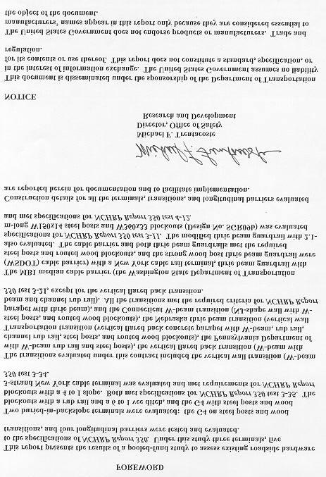
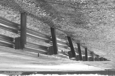
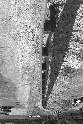
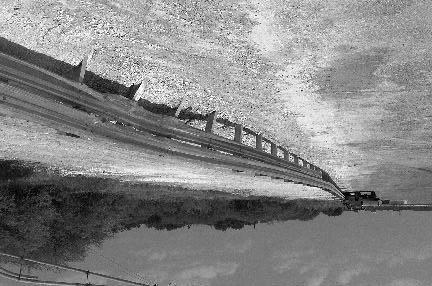
33 Posts 2 through 22 are 2440 mm long. Posts 1, A, B and the length of need posts are 1830 mm long. A vee ditch runs through the installation. It consists of a 6 to 1 slope from the pavement for 2700 mm and then a 4 to 1 backslope continuing behind the rail. The vee ditch crosses the terminal 711 mm upstream of post 8. Drawings for the buried-in-backslope end treatment are shown on page 1 of figure 1. Miscellaneous end treatment details for the installation are shown on pages 2 and 3 of figure 1. Photographs of the completed installation as tested are shown in figure 2. Soil and Weather Conditions The test was performed on the morning of January 29, A total of 18 mm of rainfall occurred eight days prior to the day of the test. No other rainfall occurred during the remaining 10 recording days prior to the test. Moisture content of the NCHRP Report 350 standard soil in which the terminal was installed was 8.3 percent at post 8, 8.6 percent at post 9, and 8.6 percent at post 10. Weather conditions the day of the test were as follows: wind speed: 9 km/h; wind direction: 180 degrees with respect to the vehicle (vehicle traveling northeasterly); temperature: 16EC; relative humidity: 84 percent. Test Vehicle A 1995 GMC 2500 pickup truck, shown in figure 3, was used for the crash test. Test inertia weight of the vehicle was 2000 kg, and its gross static weight was 2076 kg. The height to the lower edge of the vehicle bumper was 395 mm and it was 600 mm to the upper edge of the bumper. Additional dimensions and information on the vehicle are given in appendix B, figure 79. Impact Description The vehicle, traveling at 97.2 km/h, impacted the G4 W-beam guardrail backslope anchor terminal 90 mm beyond post 8, at an angle of 25.2 degrees. At s, post 8 moved and at s, post 9 moved. The vehicle began to redirect at s. At s, posts 7 and 10 moved, at s, the left front tire of the vehicle contacted post 9, and at s, post 11 moved. The dummy s head impacted the driver-side window, breaking the window at s. The rear of the vehicle contacted the rail element at s. At s, the vehicle was at post 11, traveling parallel with the guardrail at a speed of 70.7 km/h. The vehicle lost contact with the guardrail at s, traveling at a speed of 70.6 km/h and an angle of 8.1 degrees. Brakes on the vehicle were applied at 2.5 s after impact and the vehicle subsequently came to rest 66.8 m down from the point of impact and adjacent to the rail. Sequential photographs of the test period are shown in appendix C, figures 92 and 93. 9


34 10 Figure 2. G4 W-beam guardrail backslope anchor terminal installation prior to test


35 Figure 3. Vehicle before test
36 Damage to Test Article Deformation to the upper and lower W-beams extended from between post 8 and 9 to past post 11, as shown in figure 4. The flange on the top of post 8 was deformed. Tire marks on the W-beam could be seen at a point 558 mm down from post 8. On post 9, the lower W-beam was deformed, the bolt on the upper W-beam was pulled completely through, the lower part of the flange was deformed and the wood on the lower section of the block was gouged out. Maximum dynamic deflection of the W-beam during the test was 0.67 m and the maximum residual deformation after the test was 0.41 m near post 11. Vehicle Damage The vehicle sustained structural damages on the front left and left side. The left stabilizer bar, upper and lower A-arms, spindle and assembly, tire and wheel were all severely damaged. The front left portion of the bumper, hood, grill and frame were crushed as shown in figure 5. The windshield was cracked in the lower left corner and the left door was deformed to the point that it separated from the frame 90 mm at the top. The left rear quarter panel was dented and the bed shifted 20 mm to the right. The right door was jammed and the front right quarter panel was jammed into the door. The maximum crush to the front bumper was 430 mm on the front and 520 mm on the left side. The floor pan and the firewall were deformed. Maximum deformation of the occupant compartment was 45 mm in the center floor pan area. Exterior vehicle crush and occupant compartment deformation measurements are shown in appendix B, tables 25 and 26. Occupant Risk Factors Longitudinal occupant impact velocity was 7.2 m/s at s, the highest s longitudinal occupant ridedown acceleration was -9.4 g s from to s, and the maximum s average longitudinal acceleration was -6.0 g s between and s. In the lateral direction, the occupant impact velocity was 7.2 m/s at s, the highest s occupant ridedown acceleration was 8.6 g s from to s, and the maximum s average was 8.8 g s between and s. These data and other pertinent information from the test are summarized in figure 6. Vehicle angular displacements are displayed in appendix D, figure 118. Vehicular accelerations versus time traces are presented in appendix E, figures 131 through 141. Assessment of Test Results The following NCHRP Report 350 safety evaluation criteria were used to evaluate this crash test:! Structural Adequacy A. Test article should contain and redirect the vehicle; the vehicle should not penetrate, underride, or override the installation although controlled lateral deflection of the test article is acceptable. 12


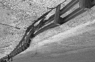
37 13 Figure 4. G4 W-beam guardrail buried-in-backslope terminal after test


38 Figure 5. Vehicle after test
 Curb... Test Inertial... Dummy... Gross Static... Texas Transportation Institute 404211-1 01/29/98 Terminal W-beam Buried in Backslope 76.")
... Angle (deg)... Occupant Risk Values Impact Velocity (m/s) x-direction... y-direction... THIV... Ridedown Accelerations (g's) x-direction... y-direction... PHD (g s).")
... Interior OCDI... Max. Occ. Compart. Deformation (mm)... Post-Impact Behavior (during 1.0 s after impact) Max.")
39 0.000 s s s s 15 General Information Test Agency... Test No.... Date... Test Article Type... Name... Installation Length (m)... Material or Key Elements... Soil Type and Condition... Test Vehicle Type... Designation... Model... Mass (kg) Curb... Test Inertial... Dummy... Gross Static... Texas Transportation Institute /29/98 Terminal W-beam Buried in Backslope 76.2 W-beam Guardrail on Steel Posts w/woodblockouts, Rub rail, 6:1 Ditch Standard Soil, Damp Production 2000P 1995 GMC 2500 Pickup Truck Impact Conditions Speed (km/h)... Angle (deg)... Exit Conditions Speed (km/h)... Angle (deg)... Occupant Risk Values Impact Velocity (m/s) x-direction... y-direction... THIV... Ridedown Accelerations (g's) x-direction... y-direction... PHD (g s)... ASI... Max s Average (g's) x-direction... y-direction... z-direction Test Article Deflections (m) Dynamic... Permanent... Vehicle Damage Exterior VDS... CDC... Maximum Exterior Vehicle Crush (mm)... Interior OCDI... Max. Occ. Compart. Deformation (mm)... Post-Impact Behavior (during 1.0 s after impact) Max. Yaw Angle (deg)... Max. Pitch Angle (deg)... Max. Roll Angle (deg) LFQ4 11FLEK2 &11LYEW3 520 FS Figure 6. Summary of results for the Buried-in-Backslope Terminal (with 6 to 1 vee ditch) test, NCHRP Report 350 test 3-35.
40 Result: The buried-in-backslope terminal with 6 to 1 vee ditch contained and redirected the vehicle. Maximum deflection of the guardrail was 0.67 m.! Occupant Risk D. Detached elements, fragments or other debris from the test article should not penetrate or show potential for penetrating the occupant compartment, or present an undue hazard to other traffic, pedestrians, or personnel in a work zone. Deformation of, or intrusions into, the occupant compartment that could cause serious injuries should not be permitted. Result: No detached elements or debris were present to penetrate or to show potential for penetrating the occupant compartment, or to present undue hazard to others in the area. Maximum deformation of the occupant compartment was 45 mm. F. The vehicle should remain upright during and after collision although moderate roll, pitching and yawing are acceptable. Result: The vehicle remained upright and stable during and after the collision.! Vehicle Trajectory K. After collision it is preferable that the vehicle s trajectory not intrude into adjacent traffic lanes. Result: The vehicle did not intrude into adjacent traffic lanes. L. The occupant impact velocity in the longitudinal direction should not exceed 12 m/s and the occupant ridedown acceleration in the longitudinal direction should not exceed 20 G s. Result: Longitudinal occupant impact velocity was 7.2 m/s and the longitudinal occupant ridedown acceleration was -9.4 g s. M. The exit angle from the test article preferably should be less than 60 percent of the test impact angle, measured at time of vehicle loss of contact with the test device. Result: Exit angle at loss of contact was 8.1 degrees, which was 32 percent of the impact angle. 16
41 The following supplemental evaluation factors and terminology were used for visual assessment of test results: PASSENGER COMPARTMENT INTRUSION 1. Windshield Intrusion a. No windshield contact b. Windshield contact, no damage c. Windshield contact, no intrusion d. Device embedded in windshield, no significant intrusion e. Complete intrusion into passenger compartment f. Partial intrusion into passenger compartment 2. Body Panel Intrusion yes or no LOSS OF VEHICLE CONTROL 1. Physical loss of control 3. Perceived threat to other vehicles 2. Loss of windshield visibility 4. Debris on pavement PHYSICAL THREAT TO WORKERS OR OTHER VEHICLES 1. Harmful debris that could injure workers or others in the area 2. Harmful debris that could injure occupants in other vehicles No debris was present. VEHICLE AND DEVICE CONDITION 1. Vehicle Damage a. None b. Minor scrapes, scratches or dents c. Significant cosmetic dents d. Major dents to grill and body panels e. Major structural damage 2. Windshield Damage a. None (stress cracking only) b. Minor chip or crack c. Broken, no interference with visibility d. Broken and shattered, visibility restricted but remained intact e. Shattered, remained intact but partially dislodged f. Large portion removed g. Completely removed 17
42 3. Device Damage a. None b. Superficial c. Substantial, but can be straightened d. Substantial, replacement parts needed for repair e. Cannot be repaired 18
43 BURIED-IN-BACKSLOPE TERMINAL (WITH 4 to 1 SLOPE) (NCHRP REPORT 350 TEST NO. 3-35) Test Conditions The test performed on this buried-in-backslope terminal (with 4 to 1 slope) was NCHRP Report 350 test designation 3-35: a 2000P vehicle impacting the beginning of the length of need of the terminal at a nominal speed and impact angle of 100 km/h and 20 degrees. The beginning of the length of need for this terminal was determined to be at post 8. Test Article A W-beam guardrail can be terminated by burying the end of the rail element into a soil berm. This type of guardrail termination installation will herein be referred to as a buried-in-backslope end treatment. The guardrail is flared across a vee ditch with its end anchored to a 1830-mm-long steel post buried in the backslope. The guardrail installation is the standard SGRO4a W-beam guardrail with wood blockouts. The guardrail between posts A, B, 1 and 2 (numbered sequentially from the end anchor) is flared back in a 4 to 1 ratio. The guardrail between posts 2 and 4 is flared back in a 6 to 1 ratio; between posts 4 and 8 in an 8 to 1 ratio; and between posts 8 and 20 in a 13 to 1 ratio. In addition, the guardrail between post 8 and post A is tapered from 705 mm to 504 mm, measured from the top of the rail to the shoulder grade. The guardrail, beginning at post 8, is parallel to the travel way and extends for 30.5 m beyond post 20 (length of need). The top of the rail for the length of need is 705 mm, measured from the shoulder grade. A LET terminal was installed on the downstream end of the installation. The buried-in-backslope end treatment consists of a W-beam guardrail attached to steel posts (PWE01) using wood blockouts (PDB01 - modified) with one 16-mm button-head bolt at every post. The 150-mm x 200-mm wood blockout is routed to fit the steel post and is 360 mm long. The W- beam is connected to the end post using a special connection bracket as shown in figure 7. A W-beam rubrail extends from post 2 to post 20. The rubrail is mounted to the steel posts with one 16-mm bolt. A 75-mm gap between the W-beam guardrail and the rubrail is maintained. The upstream end of the rubrail is connected to post 2 with the special connection bracket and the downstream end of the rubrail is connected to the back of post 20 with a 16-mm bolt. Posts 2 through 20 are 2440 mm long. Posts 1, A, B and the length-of-need posts are 1830 mm long. A vee ditch runs through the installation. It consists of a 4 to 1 slope from the pavement edge for 1830 mm and then a 2 to 1 backslope continuing behind the rail. The vee ditch crosses the rail terminal at post 8. Drawings for the buried-in-backslope end treatment are shown in figure 7. Photographs of the completed installation as tested are shown in figure 8. 19
44 20 Figure 7. Details of the G4 W-beam guardrail buried-in-backslope installation for test
45 21 Figure 7. Details of the G4 W-beam guardrail buried-in-backslope installation for test (continued).
46 22 Figure 7. Details of the G4 W-beam guardrail buried-in-backslope installation for test (continued).

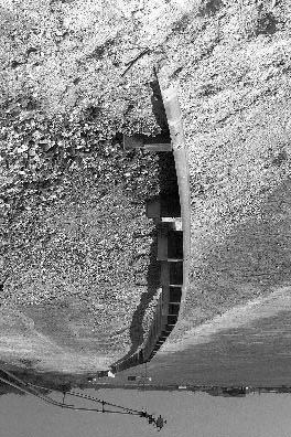
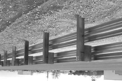
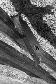
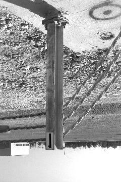
47 Figure 8. G4 W-beam guardrail buried-in-backslope installation prior to test
48 Soil and Weather Conditions The crash test was performed the morning of July 27, No rainfall was recorded for the 10 recording days prior to the test. Moisture content of the NCHRP Report 350 standard soil in which the terminal was installed was 4.2 percent, 2.4 percent, and 4.8 percent at posts 8, 10, and 12, respectively. Weather conditions at the time of testing were as follows: wind speed: 5 km/h; wind direction:180 degrees with respect to the vehicle (vehicle was traveling in a northwesterly direction); temperature: 32EC; relative humidity: 50 percent. Test Vehicle A 1995 GMC 2500 pickup truck, shown in figure 9, was used for the crash test. Test inertia weight of the vehicle was 2000 kg, and its gross static weight was 2075 kg. The height to the lower edge of the vehicle front bumper was 430 mm and to the upper edge of the front bumper was 650 mm. Additional dimensions and information on the vehicle are given in appendix B, figure 80. Impact Description The 2000P pickup truck impacted at post 8 of the buried-in-backslope terminal at a speed of km/h and impact angle of 25.9 degrees. As the vehicle contacted the installation, the left side of the vehicle was pitched downward and the left front tire was airborne. Shortly after contact, post 8 moved. Posts 9 and 10 moved at s and s, respectively. At s the vehicle began to redirect and at s the right front wheel steered toward the rail. Post 11 moved at s and post 12 moved at s. The window glass on the driver side shattered at s and the rear of the vehicle contacted the rail element at s. The vehicle became parallel with the rail element at s and was traveling at a speed of 67.6 km/h. At s the vehicle lost contact with the installation and was traveling at a speed of 65.0 km/h and an exit angle of 17.5 degrees. As the vehicle lost contact with the rail element, it yawed back toward the rail and subsequently came to rest against the length of need at post 39. The brakes on the vehicle were not applied. Sequential photographs of the test period are shown in appendix C, figures 94 and 95. Damage to Test Article The buried-in-backslope terminal sustained minimal damage as shown in figure 10. Two sections of W-beam rail element and rub rail were deformed and tire marks were on the front face of posts 9 and 10. The blockout at post 9 was detached and resting behind the installation. The tops of the blockouts at posts 10 and 11 were scarred. Length of contact of the vehicle with the installation was 6.7 m. Maximum dynamic deflection during the test was 861 mm and maximum permanent deformation was 445 mm on the rub rail and 695 mm on the upper W-beam rail element. 24


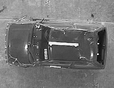
49 Figure 9. Vehicle before test
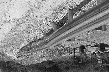
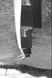
50 Figure 10. Installation after test
51 Vehicle Damage The pickup sustained moderate damage as shown in figure 11. Structural damage included deformed left front frame and left outer tie rod. Also damaged were the front bumper, hood, radiator, fan, left front tire and wheel, left front quarter panel, left door, and left rear of the bed. The windshield received stress cracks and the left door window glass was broken. Maximum exterior crush was 550 mm to the left front corner at bumper height. Maximum occupant compartment deformation was 125 mm in the center floor pan area. Exterior vehicle crush and occupant compartment measurements are shown in appendix B, tables 27 and 28. Occupant Risk Factors Data from the triaxial accelerometer, located at the vehicle center of gravity (c.g.), were digitized to compute occupant impact velocity and ridedown accelerations. The occupant impact velocity and ridedown accelerations in the longitudinal axis only are required from these data for evaluation of criterion L of NCHRP Report 350. In the longitudinal direction, occupant impact velocity was 5.4 m/s at s, maximum s ridedown acceleration was -8.3 g s from to s, and the maximum s average was -6.5 g s between and s. In the lateral direction, the occupant impact velocity was 6.5 m/s at s, the highest s occupant ridedown acceleration was 7.9 g s from to s, and the maximum s average was 7.7 g s between and s. These data and other information pertinent to the test are presented in figure 12. Vehicle angular displacements are displayed in appendix D, figure 119. Vehicular accelerations versus time traces are presented in appendix E, figures 142 through 147. Assessment of Test Results test: The following NCHRP Report 350 safety evaluation criteria were used to evaluate this crash! Structural Adequacy A. Test article should contain and redirect the vehicle; the vehicle should not penetrate, underride, or override the installation although controlled lateral deflection of the test article is acceptable. Result: The terminal contained and redirected the 2000-kg pickup truck. The vehicle did not penetrate, underride, or override the installation. Maximum dynamic deflection during the test was m. 27


52 Figure 11. Vehicle after test
 Curb... Test Inertial... Dummy... Gross Static.")

 x-direction... y-direction... PHD (g s)... ASI... Max. 0.050-s Average (g's) x-direction... y-direction... z-direction... 101.1 25.9 65.0 17.5 5.4 6.")
... Interior OCDI... Max. Occ. Compart. Deformation (mm)... Post-Impact Behavior (during 1.0 s after impact) Max. Yaw Angle (deg)... Max. Pitch Angle (deg).")
53 0.000 s s s s 29 General Information Test Agency... Test No.... Date... Test Article Type... Name... Installation Length (m)... Material or Key Elements. Soil Type and Condition. Test Vehicle Type... Designation... Model... Mass (kg) Curb... Test Inertial... Dummy... Gross Static... Texas Transportation Institute /27/00 Terminal Buried-in-Backslope w/4 to 1 slope 38.2 W-beam Guardrail on Steel posts w/wood blockouts, Rubrail, 4 to 1 Slope Standard Soil, Dry Production 2000P 1995 GMC 2500 Pickup Truck Impact Conditions Speed (km/h)... Angle (deg)... Exit Conditions Speed (km/h)... Angle (deg)... Occupant Risk Values Impact Velocity (m/s) x-direction... y-direction... THIV (km/h)... Ridedown Accelerations (g's) x-direction... y-direction... PHD (g s)... ASI... Max s Average (g's) x-direction... y-direction... z-direction Test Article Deflections (m) Dynamic Permanent Working Width Vehicle Damage Exterior VDS... CDC... Maximum Exterior Vehicle Crush (mm)... Interior OCDI... Max. Occ. Compart. Deformation (mm)... Post-Impact Behavior (during 1.0 s after impact) Max. Yaw Angle (deg)... Max. Pitch Angle (deg)... Max. Roll Angle (deg)... 11LFQ4 11FLEK2 &11LYEW3 550 LF Figure 12. Summary of results for the buried-in-backslope terminal (with 4 to 1 vee ditch) test, NCHRP Report 350 test 3-35.
54 ! Occupant Risk D. Detached elements, fragments or other debris from the test article should not penetrate or show potential for penetrating the occupant compartment, or present an undue hazard to other traffic, pedestrians, or personnel in a work zone. Deformation of, or intrusions into, the occupant compartment that could cause serious injuries should not be permitted. Result: The blockout at post 9 detached but did not penetrate or show potential for penetrating the occupant compartment, or present undue hazard to others in the area. Maximum occupant compartment deformation was 125 mm and was judged not to cause serious injury. F. The vehicle should remain upright during and after collision although moderate roll, pitching and yawing are acceptable. Result: The vehicle remained upright during and after the collision period.! Vehicle Trajectory K. After collision it is preferable that the vehicle s trajectory not intrude into adjacent traffic lanes. Result: The vehicle did not intrude into adjacent traffic lanes. L. The occupant impact velocity in the longitudinal direction should not exceed 12 m/s and the occupant ridedown acceleration in the longitudinal direction should not exceed 20 G s. Result: Longitudinal occupant impact velocity was 5.4 m/s and longitudinal ridedown acceleration was -8.3 g s. M. The exit angle from the test article preferably should be less than 60 percent of the test impact angle, measured at time of vehicle loss of contact with the test device. Result: Exit angle at loss of contact was 17.5 degrees, which was 68 percent of the impact angle; however, the vehicle yawed toward the installation and came to rest adjacent to the length of need. 30
55 The following supplemental evaluation factors and terminology were used for visual assessment of test results: PASSENGER COMPARTMENT INTRUSION 1. Windshield Intrusion a. No windshield contact b. Windshield contact, no damage c. Windshield contact, no intrusion d. Device embedded in windshield, no significant intrusion e. Complete intrusion into passenger compartment f. Partial intrusion into passenger compartment 2. Body Panel Intrusion yes or no LOSS OF VEHICLE CONTROL 1. Physical loss of control 3. Perceived threat to other vehicles 2. Loss of windshield visibility 4. Debris on pavement PHYSICAL THREAT TO WORKERS OR OTHER VEHICLES 1. Harmful debris that could injure workers or others in the area 2. Harmful debris that could injure occupants in other vehicles The blockout at post 9 detached and came to rest behind the installation. VEHICLE AND DEVICE CONDITION 1. Vehicle Damage a. None b. Minor scrapes, scratches or dents c. Significant cosmetic dents d. Major dents to grill and body panels e. Major structural damage 2. Windshield Damage a. None b. Minor chip or crack c. Broken, no interference with visibility d. Broken and shattered, visibility restricted but remained intact e. Shattered, remained intact but partially dislodged f. Large portion removed g. Completely removed 31
56 3. Device Damage a. None b. Superficial c. Substantial, but can be straightened d. Substantial, replacement parts needed for repair e. Cannot be repaired 32
57 NEW YORK TERMINAL FOR 3-CABLE BARRIER (NCHRP REPORT 350 TEST NO. 3-34) Test Conditions The test performed on the New York terminal for 3-cable barrier was NCHRP Report 350 test designation 3-34: an 820-kg passenger car impacting the terminal at a nominal impact speed and angle of 100 km/h and 15 degrees midpoint between the end of the terminal and the beginning of the length of need. The target impact point was determined to be the point at which the right front corner of the bumper of the vehicle impacted the cables in the downward-sloping portion of the anchor. Test Article A m-long New York 3-strand cable rail system was constructed for full scale crash testing of the terminal. The installation was constructed on a 6 to 1 slope as shown on page 1 of figure 13. Installation height of the system was 685 mm from the ground line to the center of the top cable. The posts were Type S75 8 steel posts spaced 5000 mm on-center. The posts were installed in NCHRP Report 350 standard soil. The three cables were each 19-mm diameter 3-strand/7-wire rope cable, spaced 76 mm apart with a minimum tensile strength of 110 kn. The cables were connected to the posts using 8-mm hooked bolts. All cable ends were fitted with open end wedge type cable socket fittings. Each cable end was attached to a standard turnbuckle assembly, bolted to a breakaway anchor angle, and anchored rigidly to a concrete footing. Additionally, the last post on each end of the installation was anchored in the concrete footing and made frangible by a slip base connection. The concrete footing for the last post and the cable anchor terminal were constructed in two units that mated together with a tongue and groove as shown on page 2 of figure 13. The last post flared back from the tangent a total distance of 1220 mm over a total distance of 7410 mm. On one end of each of the cables, adjacent to the standard turnbuckle, a spring cable end assembly was attached. The spring cable assembly consisted of the standard turnbuckle with 305 mm of take-up, a 20-mm diameter threaded steel rod on each end, and a spring compensating device on one end. The spring compensating device had a spring rate of N/mm and a total minimum throw of 150 mm. For the temperature conditions present just prior to the time the crash test was performed (29EC), the spring compensator was compressed 54 mm. Construction details are shown on pages 2 and 3 of figure 13. Photographs of the completed test installation are shown in figure 14. The concrete footing for the cable anchor terminal and the last post (each integral unit) were constructed in two units that mated together with a tongue and groove. Each unit measured 660 mm by 1005 mm at the top and tapered to 725 mm by 1150 mm at the bottom. The height of the footing along the centerline of the post and terminal was 990 mm. The tops of the terminal units were constructed on a 6 to 1 slope. The units were connected together by an integral key way measuring 50 mm by 100 mm at the bottom and 50 mm by 150 mm at the top. 33
58 34 Figure 13. Details of the New York cable rail terminal installation for test
59 35 Figure 13. Details of the New York cable rail terminal installation for test (continued).


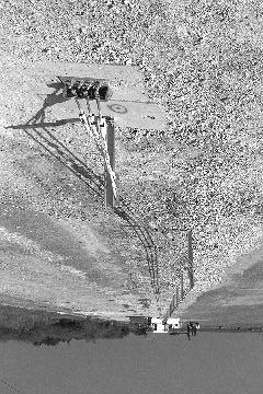
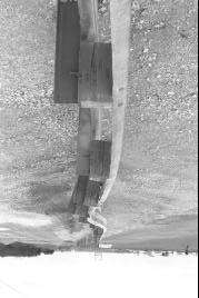
60 Figure 14. New York cable rail terminal installation prior to test
61 Soil and Weather Conditions The test was performed the morning of October 1, No rainfall occurred during the 10 recording days prior to the test. Moisture content of the NCHRP Report 350 soil in which the terminal was installed was between 6.9 and 7.5 percent. Weather conditions during the time of the test were as follows: wind speed: 8 km/h; wind direction: 190 degrees with respect to the vehicle (vehicle was traveling in a northwesterly direction); temperature: 31EC; relative humidity: 64 percent. Test Vehicle A 1992 Ford Festiva, shown in figure 15, was used for the crash test. Test inertia weight of the vehicle was 820 kg, and its gross static weight was 896 kg. The height to the lower edge of the vehicle bumper was 355 mm and it was 530 mm to the upper edge of the bumper. Additional dimensions and information on the vehicle are given in appendix B, figure 81. Impact Description The vehicle, traveling at 99.3 km/h, impacted the New York terminal at 14.7 degrees. Initial contact with the terminal was such that the right front corner of the bumper of the vehicle impacted the cables in the downward-sloping portion of the anchor. Approximately s after impact, the vehicle bumper contacted the end post (post 1), which activated at the slip base. The front right tire contacted the post at s and knocked the post to the ground. The right rear wheel lost contact with the ground at s and the right front at s. The vehicle lost contact with the terminal at s while traveling at a speed of 94.4 km/h and an exit angle behind the terminal of 15.7 degrees. The vehicle continued to travel down the slope of the ditch and the right side wheels touched ground again at s and s as the vehicle reached the field side of the ditch. The vehicle then traversed up the slope and traveled out of what would be the right of way and into private property. Brakes on the vehicle were not applied. As the vehicle entered the brushy area beyond the right of way, it yawed clockwise and rolled onto its left side for reasons not related to the performance of the guardrail (the vehicle impacted a large bush). The vehicle came to rest 42.5 m down from impact and 25.0 m behind the installation. Sequential photographs of the test period are shown in appendix C, figures 96 and 97. Damage to Test Article Damage to the 3-cable New York cable rail terminal was minimal as shown in figure 16. The end post broke away at the slip base and was found 480 mm from the base. The rear bolt on the right side remained on the base and the rear bolt from the left side was lying near the base. The two bolts on the front remained with the end post. The turnbuckles near the anchor plate and the cables received scuff marks from the vehicle tires. The cables were slack throughout the length of the installation, but neither anchor moved. 37


62 Figure 15. Vehicle before test


63 39 Figure 16. New York cable rail terminal after test
64 Vehicle Damage The vehicle sustained little damage from impact with the terminal. Structural damage included a deformed lower control arm and strut tower and a torn upper right strut mount. Minor damage occurred to the front bumper. The front right rim was bent and the tire deflated. After the vehicle exited the test site (traversed the sloped ditch and traveled beyond the right of way) the vehicle yawed clockwise and rolled onto its left side. Photographs of the vehicle after the test are shown in figure 17; however, most of the damage occurred during the rollover. No measurable deformation occurred to the front of the vehicle from impact with the terminal. No deformation or intrusion of the occupant compartment occurred prior to the rollover. Exterior crush and occupant compartment measurements are shown in appendix B, tables 29 and 30. Occupant Risk Factors In the longitudinal direction, the occupant impact velocity was 1.8 m/s at s, the highest s occupant ridedown acceleration was -3.1 g s from to s, and the maximum s average acceleration was -2.3 g s between and s. In the lateral direction, the occupant impact velocity was 0.9 m/s at s, the highest s occupant ridedown acceleration was -3.0 g s from to s, and the maximum s average was -1.4 g s between and s. These data and other pertinent information from the test are summarized in figure 18. Vehicle angular displacements are displayed in appendix D, figure 120. Vehicular accelerations versus time traces are presented in appendix E, figures 148 through 157. Assessment of Test Results test: The following NCHRP Report 350 safety evaluation criteria were used to evaluate this crash! Structural Adequacy C. Acceptable test article performance may be by redirection, controlled penetration, or controlled stopping of the vehicle. Result: The New York Terminal for 3-cable barrier allowed the vehicle to gate through the end.! Occupant Risk D. Detached elements, fragments or other debris from the test article should not penetrate or show potential for penetrating the occupant compartment, or present an undue hazard to other traffic, pedestrians, or personnel in a work zone. Deformation of, or intrusions into, the occupant compartment that could cause serious injuries should not be permitted. 40


65 41 Figure 17. Vehicle after test
 Curb... Test Inertial... Dummy... Gross Static.")
.")
 x-direction... y-direction... PHD (g s)... ASI... Max. 0.050-s Average (g's) x-direction... y-direction... z-direction... 99.3 14.7 94.4 15.")
... nil Interior OCDI... RF0000000 Max. Occ. Compart. Deformation (mm)... 0 Post-Impact Behavior (during 1.")
66 0.000 s s s s 42 General Information Test Agency... Test No.... Date... Test Article Type... Name... Installation Length (m)... Material or Key Elements. Soil Type and Condition. Test Vehicle Type... Designation... Model... Mass (kg) Curb... Test Inertial... Dummy... Gross Static... Texas Transportation Institute /01/98 Terminal New York 3-Cable Guardrail Terminal mm Diameter Wire Rope Cables With Embedded Concrete Anchor Block Standard Soil, Dry Production 820C 1992 Ford Festiva Impact Conditions Speed (km/h)... Angle (deg)... Exit Conditions Speed (km/h)... Angle (deg)... Occupant Risk Values Impact Velocity (m/s) x-direction... y-direction... THIV (km/h)... Ridedown Accelerations (g's) x-direction... y-direction... PHD (g s)... ASI... Max s Average (g's) x-direction... y-direction... z-direction Test Article Deflections (m) Dynamic... nil Permanent... nil Vehicle Damage Exterior VDS... 12FR1 CDC... 12FRLN1 Maximum Exterior Vehicle Crush (mm)... nil Interior OCDI... RF Max. Occ. Compart. Deformation (mm)... 0 Post-Impact Behavior (during 1.0 s after impact) Max. Yaw Angle (deg) Max. Pitch Angle (deg) Max. Roll Angle (deg) Figure 18. Summary of results for the New York terminal test, NCHRP Report 350 test 3-34.
67 Result: No detached elements, fragments or debris were present to penetrate or to show potential for penetrating the occupant compartment, or to present undue hazard to others in the area. No deformation or intrusion of the occupant compartment occurred. F. The vehicle should remain upright during and after collision although moderate roll, pitching and yawing are acceptable. Result: The vehicle remained upright during and immediately after the collision period, but rolled onto its side after exiting the test site for reasons not related to the performance of the guardrail. H. Occupant impact velocities should satisfy the following: Longitudinal and Lateral Occupant Impact Velocity - m/s Preferred Maximum 9 12 Result: Longitudinal occupant impact velocity was 1.8 m/s and lateral occupant impact velocity was 0.9 m/s I. Occupant ridedown accelerations should satisfy the following: Longitudinal and Lateral Occupant Ridedown Accelerations - g's Preferred Maximum Result: Longitudinal ridedown acceleration was -3.1 g s and lateral ridedown acceleration was -3.0 g s! Vehicle Trajectory K. After collision it is preferable that the vehicle s trajectory not intrude into adjacent traffic lanes. Result: The vehicle did not intrude into adjacent traffic lanes. N. Vehicle trajectory behind the test article is acceptable. Result: The vehicle came to rest behind the test article. The following supplemental evaluation factors and terminology were used for visual assessment of test results: 43
68 PASSENGER COMPARTMENT INTRUSION 1. Windshield Intrusion a. No windshield contact b. Windshield contact, no damage c. Windshield contact, no intrusion d. Device embedded in windshield, no significant intrusion e. Complete intrusion into passenger compartment f. Partial intrusion into passenger compartment 2. Body Panel Intrusion yes or no LOSS OF VEHICLE CONTROL 1. Physical loss of control 3. Perceived threat to other vehicles 2. Loss of windshield visibility 4. Debris on pavement PHYSICAL THREAT TO WORKERS OR OTHER VEHICLES 1. Harmful debris that could injure workers or others in the area 2. Harmful debris that could injure occupants in other vehicles No debris was present. VEHICLE AND DEVICE CONDITION 1. Vehicle Damage a. None b. Minor scrapes, scratches or dents c. Significant cosmetic dents 2. Windshield Damage a. None b. Minor chip or crack c. Broken, no interference with visibility d. Broken and shattered, visibility restricted but remained intact d. Major dents to grill and body panels e. Major structural damage e. Shattered, remained intact but partially dislodged f. Large portion removed g. Completely removed 3. Device Damage a. None b. Superficial c. Substantial, but can be straightened d. Substantial, replacement parts needed for repair e. Cannot be repaired 44
69 TRANSITIONS According to NCHRP Report 350, two tests are required to evaluate transitions to test level three (TL-3), as described below. NCHRP Report 350 test designation 3-20: An 820-kg passenger car impacting the transition at the critical impact point (CIP) of the transition at a nominal speed and angle of 100 km/h and 20 degrees. The test is intended to evaluate occupant risk and postimpact trajectory. NCHRP Report 350 test designation 3-21: A 2000-kg pickup truck impacting the transition at the CIP of the transition at a nominal speed and angle of 100 km/h and 25 degrees. The test is intended to evaluate strength of the section in containing and redirecting the 2000-kg vehicle. NCHRP Report 350 test 3-21 was the only test performed on all the transition tests reported herein. As suggested in NCHRP Report 350, the BARRIER VII computer simulation program was used to determine the CIP in each of these tests. VERTICAL WALL TRANSITION TEST 2 (NCHRP REPORT 350 TEST NO. 3-21) Test Conditions The test performed on the vertical wall transition was NCHRP Report 350 test The BARRIER VII program indicated the CIP to be 1.5 m from the end of the vertical wall concrete parapet. Test Article This test was performed on the W-beam with W-beam rub rail and steel posts transition to the vertical concrete bridge rail. This is a modification to the standard detailed in Figure 1B of FHWA Technical Advisory No. T dated January 28, A reinforced concrete parapet wall with a spread footing was constructed according to the drawings on page 1 of figure 19. The wall was 810 mm high from the roadway surface. It tapered from a vertical face at the rail transition to a NJ-shape bridge rail over 3.2 m. The spread footing was 3.2 m by 2.18 m in area. The top of the spread footing was 450 mm below the roadway surface and was 900 mm deep. A 2.4-m-long by 810-mm-high F-shape simulated bridge rail was constructed adjacent to the parapet wall. 45
70 46 Figure 19. Details of the vertical wall transition installation for test
71 47 Figure 19. Details of the vertical wall transition installation for test (continued).
72 A standard W-beam guardrail with steel posts and wood blockouts is transitioned over a length of 3.8 m to the concrete parapet wall, as shown on page 2 of figure 19. The center of the guardrail is mounted 550 mm above the ground at the rail. The two nested W-beam guardrail elements are attached to a RWE02a terminal connector with eight standard guardrail connector bolts. The terminal connector is bolted through formed holes in the parapet wall with four M22x250 mm H.S. (high strength) hex bolts with a standard FPB02 terminal connector bearing plate on the back of the parapet wall. Posts 1, 2, 3, 5, and 7 are not connected to the rail. Post 4 is connected to the rail with an FBB03 guardrail bolt and recess nut with a rectangular plate washer under the bolt head and a steel washer under the nut. Posts 7 and 8 have backup plates. The standard guardrail section begins at post 9. The 150-mm x 200-mm routed wood blockout was used behind the guardrail at all posts. The center of the rub rail is mounted 190 mm above the ground at the rail. The W-beam rub rail is attached to a RWE02a terminal connector with eight standard guardrail connector bolts. The terminal connector is bolted through formed holes in the parapet wall with four M22x250 mm H.S. hex bolts with a standard FPB02 terminal connector bearing plate on the back of the parapet wall. Posts 1, 2, 3, and 5 are not connected to the rub rail. Post 4 is connected to the rub rail with an FBB03 guardrail bolt and recess nut with a rectangular plate washer under the bolt head and a steel washer under the nut. The 100-mm-wide x 360-mm-long wood blockout used behind the rub rail at posts 1, 2, 3, and 4 was tapered to allow the rub rail to be flush at the parapet wall and connect behind post 6. Posts 1 and 2 are W200x19 by 2285-mm-long steel posts. Posts 3 thru 13 are standard PWE02 steel posts. The post spacing between the parapet wall, posts 1, 2, 3, and 4 is 476 mm. The post spacing between posts 4, 5, 6, 7, and 8 is 953 mm. The post spacing for the standard guardrail section is 1905 mm. The guardrail is anchored at the upstream end with a standard ET The completed installation is shown in figure 20. Soil and Weather Conditions The test was performed the morning of July 27, No rainfall occurred during the 10 recording days prior to the test. Moisture content of the NCHRP Report 350 standard soil in which the installation was constructed was 4.7 percent, 6.1 percent, and 5.5 percent at posts 1, 3 and 5, respectively. Weather conditions during the time of the test were as follows: wind speed: 10 km/h; wind direction: 15 degrees with respect to the vehicle (vehicle was traveling in a south/southwesterly direction); temperature: 33EC; relative humidity: 58 percent. Test Vehicle A 1995 Chevrolet 2500 pickup truck, shown in figure 21, was used for the crash test. Test inertia weight of the vehicle was 2000 kg, and its gross static weight was 2074 kg. The height to 48


73 Figure 20. Vertical wall transition prior to test


74 Figure 21. Vehicle before test
75 the lower edge of the vehicle bumper was 440 mm and it was 660 mm to the upper edge of the bumper. Additional dimensions and information on the vehicle are given in appendix B, figure 82. Impact Description The vehicle, traveling at 97.5 km/h, impacted the vertical wall transition 1.5 m from the end of the bridge parapet at a 25.5-degree angle. Shortly after impact, posts 3 and 4 moved followed by movement at post 2 and then 1. At s redirection of the vehicle occurred. The concrete wall moved at s. The top of the passenger s side door separated from the cab of the vehicle at s, and the windshield cracked at s. At s the left front tire lost contact with the ground. The rear right and left tires lost contact with the ground at and s, respectively. The right rear tire contacted the rail at s, and the right front tire lost contact with the ground. At s the right rear tire snagged on the rail and at s the tire blew out. At s the vehicle began to roll clockwise. The vehicle, traveling at 66.5 km/h, was parallel to the installation at s. The right front tire contacted the ground at s. The vehicle lost contact with the transition at s, and was traveling at 52.5 km/h and an exit angle of 7.3 degrees. As the vehicle exited the transition, the vehicle continued to roll clockwise and touched down on its right front corner. Brakes on the vehicle were not applied. The truck slid to a stop on its right side 44.2 m down from impact point and 3.0 m toward traffic lanes. Sequential photographs of the test period are shown in appendix C, figures 98 and 99. Damage to Test Article The vertical wall transition received moderate damage as shown in figure 22. The rail was deformed from post 5 through post 1. The blockout on the upper rail element at post 1 was split and separated from the post. The blockout on the rub rail at post 1 was split but remained attached. The blockout on the upper rail element at post 2 was gouged. A piece of metal from the vehicle was caught on the edge of the connection at the end shoe. The top of the CMB was scraped from contact with the vehicle. Total length of contact of the vehicle with the transition and CMB was 4.24 m. Maximum permanent deformation of the rail was 90 mm at post 2. Vehicle Damage The vehicle sustained substantial damage as shown in figure 23. Structural damage included the right front spindle, rod ends, stabilizer bar, front cross member, upper and lower A-arms, right side floor pan, firewall, and frame. The right rear axle springs, U-bolts, and right A-pillar sustained damage. The right front and rear tire and wheel were crushed. Both right side quarter panels were damaged and the right door had a 355-mm gap at the top. The fan, radiator, grill, hood, and bumper were deformed. The left front quarter panel was damaged and the left door was jammed. The windshield was shattered. A 20-mm buckle was noted on the passenger s side of the cab and the cab shifted out 70 mm on the driver s side. Maximum exterior crush to the vehicle was 540 mm at the top of the front bumper and 530 mm at the wheel well. Occupant compartment deformation was 40 mm in the floor to instrument panel area and 97 mm in the firewall area. Details can be found in appendix B, tables 31 and
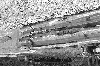
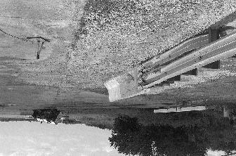
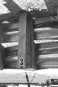
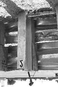
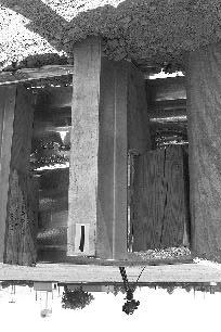
76 Figure 22. Installation after test


77 53 After being righted Figure 23. Vehicle after test
78 Occupant Risk Factors In the longitudinal direction, the occupant impact velocity was 9.1 m/s at s, the highest s occupant ridedown acceleration was g s from to s, and the maximum s average acceleration was g s between and s. In the lateral direction, the occupant impact velocity was 7.8 m/s at s, the highest s occupant ridedown acceleration was 12.5 g s from to s, and the maximum s average was g s between and s. These data and other pertinent information from the test are summarized in figure 24. Vehicle angular displacements are displayed in appendix D, figure 121. Vehicular accelerations versus time traces are presented in appendix E, figures 158 through 168. Assessment of Test Results test: The following NCHRP Report 350 safety evaluation criteria were used to evaluate this crash! Structural Adequacy A. Test article should contain and redirect the vehicle; the vehicle should not penetrate, underride, or override the installation although controlled lateral deflection of the test article is acceptable. Result: The vertical wall transition contained and redirected the vehicle. The vehicle did not penetrate, underride, or override the installation. Maximum permanent deformation was 0.01 m.! Occupant Risk D. Detached elements, fragments or other debris from the test article should not penetrate or show potential for penetrating the occupant compartment, or present an undue hazard to other traffic, pedestrians, or personnel in a work zone. Deformation of, or intrusions into, the occupant compartment that could cause serious injuries should not be permitted. Result: No detached elements, fragments, or other debris were present to penetrate or to show potential for penetrating the occupant compartment, or to present undue hazard to others in the area. Maximum reduction of space was 27 percent in the center floor pan area, which may cause serious injury. F. The vehicle should remain upright during and after collision although moderate roll, pitching and yawing are acceptable. Result: The vehicle rolled onto its right side after exiting the installation. 54
 Curb... Test Inertial... Dummy... Gross Static.")

 x-direction... y-direction... PHD (g s)... ASI... Max. 0.050-s Average (g's) x-direction... y-direction... z-direction... 97.5 25.5 52.5 7.3 9.1 7.")
... Post-Impact Behavior (during 1.0 s after impact) Max. Yaw Angle (deg)... Max. Pitch Angle (deg)... Max. Roll Angle (deg).")
79 0.000 s s s s 55 General Information Test Agency... Test No.... Date... Test Article Type... Name... Installation Length (m)... Material or Key Elements. Soil Type and Condition. Test Vehicle Type... Designation... Model... Mass (kg) Curb... Test Inertial... Dummy... Gross Static... Texas Transportation Institute /27/98 Transition Vertical Wall Transition 35.3 W-beam with W-beam Rub Rail & Steel Posts to Vertical Concrete Bridge Rail Standard Soil, Dry Production Chevrolet Pickup Truck Impact Conditions Speed (km/h)... Angle (deg)... Exit Conditions Speed (km/h)... Angle (deg)... Occupant Risk Values Impact Velocity (m/s) x-direction... y-direction... THIV (km/h)... Ridedown Accelerations (g's) x-direction... y-direction... PHD (g s)... ASI... Max s Average (g's) x-direction... y-direction... z-direction Test Article Deflections (m) Dynamic... Permanent... Vehicle Damage Exterior VDS... CDC... Maximum Exterior Vehicle Crush (mm)... Interior OCDI... Max. Occ. Compart. Deformation (mm)... Post-Impact Behavior (during 1.0 s after impact) Max. Yaw Angle (deg)... Max. Pitch Angle (deg)... Max. Roll Angle (deg)... N/A RFQ5 01FREK4 & 01RDEW4 540 FS Figure 24. Summary of results for the first test on the vertical wall transition, NCHRP Report 350 test 3-21.
80 ! Vehicle Trajectory K. After collision it is preferable that the vehicle s trajectory not intrude into adjacent traffic lanes. Result: The vehicle did intrude into adjacent traffic lanes. L. The occupant impact velocity in the longitudinal direction should not exceed 12 m/s and the occupant ridedown acceleration in the longitudinal direction should not exceed 20 G s. Result: Longitudinal occupant impact velocity was 9.1 m/s and longitudinal ridedown acceleration was g s. M. The exit angle from the test article preferably should be less than 60 percent of the test impact angle, measured at time of vehicle loss of contact with the test device. Result: Exit angle at loss of contact was 7.3 degrees, which was less than 60 percent of the impact angle. The following supplemental evaluation factors and terminology were used for visual assessment of test results: PASSENGER COMPARTMENT INTRUSION 1. Windshield Intrusion a. No windshield contact b. Windshield contact, no damage c. Windshield contact, no intrusion d. Device embedded in windshield, no significant intrusion e. Complete intrusion into passenger compartment f. Partial intrusion into passenger compartment 2. Body Panel Intrusion yes or no LOSS OF VEHICLE CONTROL 1. Physical loss of control 3. Perceived threat to other vehicles 2. Loss of windshield visibility 4. Debris on pavement 56
81 PHYSICAL THREAT TO WORKERS OR OTHER VEHICLES 1. Harmful debris that could injure workers or others in the area 2. Harmful debris that could injure occupants in other vehicles No debris was present. VEHICLE AND DEVICE CONDITION 1. Vehicle Damage a. None b. Minor scrapes, scratches or dents c. Significant cosmetic dents d. Major dents to grill and body panels e. Major structural damage 2. Windshield Damage a. None (during test) b. Minor chip or crack c. Broken, no interference with visibility (after roll over) d. Broken and shattered, visibility restricted but remained intact e. Shattered, remained intact but partially dislodged f. Large portion removed g. Completely removed 3. Device Damage a. None b. Superficial c. Substantial, but can be straightened d. Substantial, replacement parts needed for repair e. Cannot be repaired 57
82 VERTICAL WALL TRANSITION TEST 12 (NCHRP REPORT 350 TEST NO. 3-21) Test Conditions This test was a repeat of NCHRP Report 350 test The BARRIER VII program indicated the CIP to be 1.5 m from the end of the vertical wall concrete parapet. Test Article This test was performed on this transition previously (Test 2). When constructing the installation for the previous test, the end shoe would fit properly only if lapped over the W-beams. During the test the vehicle snagged on the exposed end of the end shoe and the vehicle rolled onto its side after exiting the transition. The installation used for the last test was repaired for use in the repeat test. The end shoe was modified to fit while lapped under the W-beams when installed on the W-beam with W-beam rub rail and steel posts transition. The holes in the terminal connector were enlarged with a drift pin (punch) so that the splice bolts could be installed with the terminal connector lapped under the W-beams. The terminal connector was then bolted through formed holes in the parapet wall with four M22x250 mm high strength (H.S.) hex bolts with a standard FPB02 terminal connector bearing plate on the back of the parapet wall. Drawings of the installation were shown previously in figure 19. Photographs of the completed installation as tested are shown in figure 25. Soil and Weather Conditions The crash test was performed the morning of November 5, A total of 41 mm of rain was recorded four days before the test. No other rainfall was recorded for the 10 days prior to the test. Moisture content was 8.1 percent, 8.2 percent, and 8.4 percent at posts 1, 3, and 5, respectively. Weather conditions at the time of testing were as follows: wind speed: 13 km/h; wind direction: 180 degrees with respect to the vehicle (vehicle was traveling in a southerly direction); temperature: 12EC; relative humidity: 57 percent. Test Vehicle A 1994 Chevrolet 2500 pickup truck, shown in figure 26, was used for the crash test. Test inertia weight of the vehicle was 2000 kg, and its gross static weight was 2077 kg. The height to the lower edge of the vehicle front bumper was 385 mm and to the upper edge of the front bumper was 615 mm. Additional dimensions and information on the vehicle are given in appendix B, figure


83 Figure 25. Vertical wall transition prior to test


84 Figure 26. Vehicle before test
85 Impact Description The vehicle, traveling at km/h, impacted the transition 1.6 m from the end of the concrete parapet at an angle of 24.2 degrees. Shortly after impact posts 4, 3, and 2 moved. At s the right front tire contacted the W-beam and then steered left. By s post 4 moved and at s the concrete parapet moved. The right front wheel was traveling parallel with the rail and the tire impacted the rub rail at s. Redirection of the vehicle began at s and at s the vehicle was traveling parallel with the rail at a speed of 79.6 km/h. The rear of the vehicle contacted the W-beam at s. The vehicle lost contact with the transition and parapet at s, and was traveling at a speed of 73.3 km/h and an exit angle of 13.9 degrees. Maximum roll during the 1.0 s after impact was 25 degrees. Brakes on the vehicle were applied at 1.75 s after impact and the vehicle subsequently came to rest 54.1 m beyond impact and 8.4 m toward traffic lanes. Sequential photographs of the test period are shown in appendix C, figures 100 and 101. Damage to Test Article Minimal damage was sustained by the transition as shown in figure 27. The top blockout at post 1 was split and the W-beam and rub rail were deformed. Maximum deformation of the W-beam rail element was 25 mm and the rub rail sustained a maximum deformation of 15 mm. The edge of the parapet wall was chipped. Total length of contact of the vehicle with the transition was 3.84 m. Vehicle Damage The vehicle sustained structural damage to the right side frame rail, right front upper and lower A-arms, and floor pan. The drive shaft was separated, the right rear U-bolts broke at the axle and the shock pulled out. As shown in figure 28, the front bumper, grill, radiator, fan, right front tire and rim, right front quarter panel, right door, right rear quarter panel, rear bumper, and right rear tire and rim were damaged. The windshield was shattered and the cab was pushed rearward into the bed. The front end of the vehicle was shifted to the left 140 mm. Maximum exterior crush to the vehicle was 500 mm at the right corner at bumper height. Maximum occupant compartment deformation was 80 mm in the lateral direction near the occupant s feet. Exterior vehicle crush and occupant compartment measurements are shown in appendix B, tables 33 and 34. Occupant Risk Factors Longitudinal occupant impact velocity was 7.3 m/s at s, maximum s ridedown acceleration was -6.7 g s from to s, and the maximum s average was g s between and s. These data and other information pertinent to the test are presented in figure 29. Vehicle angular displacements are displayed in appendix D, figure 122. Vehicular accelerations versus time traces are presented in appendix E, figures 169 through

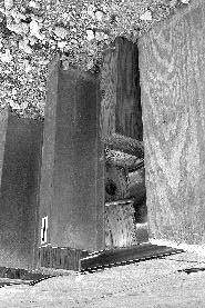
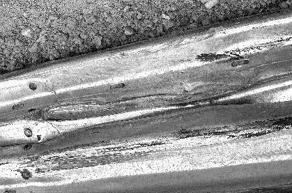
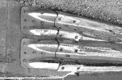
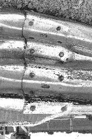
86 62 Figure 27. Installation after test


87 Figure 28. Vehicle after test
 Curb... Test Inertial... Dummy... Gross Static.")

 x-direction... y-direction... PHD (g s)... ASI... Max. 0.050-s Average (g's) x-direction... y-direction... z-direction... 101.3 24.2 73.3 13.9 7.")
... Post-Impact Behavior (during 1.0 s after impact) Max. Yaw Angle (deg)... Max. Pitch Angle (deg)... Max. Roll Angle (deg).")
88 0.000 s s s s 64 General Information Test Agency... Test No.... Date... Test Article Type... Name... Installation Length (m)... Material or Key Elements. Soil Type and Condition. Test Vehicle Type... Designation... Model... Mass (kg) Curb... Test Inertial... Dummy... Gross Static... Texas Transportation Institute /05/98 Transition Vertical Wall Transition 35.3 W-Beam With W-Beam Rub Rail & Steel Posts to Vertical Concrete Bridge Rail Standard Soil, Damp Production 2000P 1994 Chevrolet 2500 Pickup Truck Impact Conditions Speed (km/h)... Angle (deg)... Exit Conditions Speed (km/h)... Angle (deg)... Occupant Risk Values Impact Velocity (m/s) x-direction... y-direction... THIV (km/h)... Ridedown Accelerations (g's) x-direction... y-direction... PHD (g s)... ASI... Max s Average (g's) x-direction... y-direction... z-direction Test Article Deflections (m) Dynamic... Permanent... Vehicle Damage Exterior VDS... CDC... Maximum Exterior Vehicle Crush (mm)... Interior OCDI... Max. Occ. Compart. Deformation (mm)... Post-Impact Behavior (during 1.0 s after impact) Max. Yaw Angle (deg)... Max. Pitch Angle (deg)... Max. Roll Angle (deg) RFQ4 01FYEK2 & 01RDEW3 500 RF Figure 29. Summary of results for the repeat test on the vertical wall transition, NCHRP Report 350 test 3-21.
89 Assessment of Test Results test: The following NCHRP Report 350 safety evaluation criteria were used to evaluate this crash! Structural Adequacy A. Test article should contain and redirect the vehicle; the vehicle should not penetrate, underride, or override the installation although controlled lateral deflection of the test article is acceptable. Result: The W-beam with W-beam rub rail on steel posts transition to the vertical concrete bridge railing contained and redirected the vehicle. The vehicle did not penetrate, override, or underride the installation.! Occupant Risk D. Detached elements, fragments or other debris from the test article should not penetrate or show potential for penetrating the occupant compartment, or present an undue hazard to other traffic, pedestrians, or personnel in a work zone. Deformation of, or intrusions into, the occupant compartment that could cause serious injuries should not be permitted. Result: No detached elements, fragments, or other debris were present to penetrate or to show potential for penetrating the occupant compartment, or to present undue hazard to others in the area. Maximum occupant compartment deformation was 80 mm in the lateral direction near the occupant s feet. F. The vehicle should remain upright during and after collision although moderate roll, pitching and yawing are acceptable. Result: The vehicle remained upright during and after the collision event.! Vehicle Trajectory K. After collision it is preferable that the vehicle s trajectory not intrude into adjacent traffic lanes. Result: The vehicle came to rest 8.4 m toward traffic lanes and may intrude into adjacent traffic lanes. 65
90 L. The occupant impact velocity in the longitudinal direction should not exceed 12 m/s and the occupant ridedown acceleration in the longitudinal direction should not exceed 20 g s. Result: Longitudinal occupant impact velocity was 7.3 m/s and ridedown acceleration was g s. M. The exit angle from the test article preferably should be less than 60 percent of the test impact angle, measured at time of vehicle loss of contact with the test device. Results: Exit angle at loss of contact was 13.9 degrees, which was 57 percent of the impact angle. The following supplemental evaluation factors and terminology were used for visual assessment of test results: PASSENGER COMPARTMENT INTRUSION 1. Windshield Intrusion a. No windshield contact b. Windshield contact, no damage c. Windshield contact, no intrusion d. Device embedded in windshield, no significant intrusion e. Complete intrusion into passenger compartment f. Partial intrusion into passenger compartment 2. Body Panel Intrusion yes or no LOSS OF VEHICLE CONTROL 1. Physical loss of control 3. Perceived threat to other vehicles 2. Loss of windshield visibility 4. Debris on pavement PHYSICAL THREAT TO WORKERS OR OTHER VEHICLES 1. Harmful debris that could injure workers or others in the area 2. Harmful debris that could injure occupants in other vehicles No debris was present. 66
91 VEHICLE AND DEVICE CONDITION 1. Vehicle Damage a. None b. Minor scrapes, scratches or dents c. Significant cosmetic dents d. Major dents to grill and body panels e. Major structural damage 2. Windshield Damage a. None b. Minor chip or crack c. Broken, no interference with visibility d. Broken and shattered, visibility restricted but remained intact e. Shattered, remained intact but partially dislodged f. Large portion removed g. Completely removed 3. Device Damage a. None b. Superficial c. Substantial, but can be straightened d. Substantial, replacement parts needed for repair e. Cannot be repaired 67
92 VERTICAL FLARED BACK TRANSITION (NCHRP REPORT 350 TEST NO. 3-21) Test Conditions NCHRP Report 350 test designation 3-21 was performed on the vertical flared back transition. The BARRIER VII program indicated the CIP to be 1.5 m from the end of the vertical wall concrete parapet. Test Article The W-beam with W-beam rub rail and steel posts transition to the vertical flared back concrete bridge rail consisted of a portion of simulated bridge rail, a wingwall, a transition, a length of approach guardrail, and a guardrail terminal. Drawings for this transition are presented in figure 30. Photographs of the completed test installation are shown in figure 31. The concrete safety shape simulated bridge rail was 2440 mm long and had a foundation wall that extended 1200 mm below grade. The wingwall extended from the simulated bridge rail a longitudinal distance of 3900 mm. The wingwall was embedded 1200 mm below grade. The traffic face of the wingwall transitioned from a safety shape to a vertical face over a distance of 2300 mm. The vertical face extended another 750 mm and then flared back a distance of 215 mm over a longitudinal distance of 850 mm. The approach guardrail (7620 mm long) was a 2.67-mm-thick (12-ga) W-beam mounted on W150X14 steel posts spaced at 1905 mm with 150 mm x 200 mm routed wood blockouts. Mounting height to the top of the rail element was 706 mm. An ET-2000 terminal (15.24 mm long) was installed on the end of the guardrail. The transition, starting from the guardrail end, consisted of a 3810-mm length of 2.67-mm-thick (12-ga) W-beam mounted on W150x14 steel posts and 150 x 200 routed wood blockouts. Mounting height of the rail element was 685 mm to the top. Proceeding toward the transition, two nested, mm-thick (12-ga) W-beam sections were used and connected to the concrete parapet with a mm-thick (12-ga) standard terminal connector. A mm-diameter by 250-mm-long steel spacer tube was installed as a blockout between the W-beam and flared back parapet. The first four posts adjacent to the parapet were spaced at 476 mm. The first three posts adjacent to the parapet were W200x19x2290 long and were embedded 1605 mm into the ground. The remaining posts in the transition (posts 4 8) were W150x15x1980 steel posts and were embedded 1250 mm into the ground. The rub rail consisted of a length of C152x12.2 and a length of channel made from bent plate. Tapered wood blockouts were used at the first three posts, no blockout at post 4, and the rub rail was bent back and terminated on the field side of post 5. The centerline height of the rub rail was 230 mm. 68
93 69 Figure 30. Details of the vertical flared back transition installation for test
94 70 Figure 30. Details of the vertical flared back transition installation for test (continued).
95 71 Figure 30. Details of the vertical flared back transition installation for test (continued).


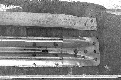
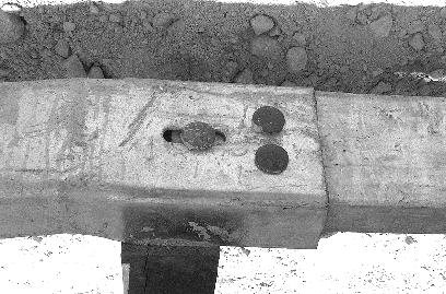
96 72 Figure 31. Vertical flared back transition prior to test
97 Holes, 610 mm in diameter, were drilled for each post. The post was installed and the hole backfilled with NCHRP Report 350 standard soil (Georgetown crushed limestone). Similar backfill was used around the wingwall and the foundation for the simulated bridge rail. Soil and Weather Conditions The test was performed the morning of September 3, Only a trace of rain was recorded during the 10 recording days prior to the test. Moisture content of the NCHRP Report 350 soil in which the transition was installed was 9.1 percent, 8.9 percent, and 7.3 percent at posts 1, 3, and 5, respectively. Weather conditions during the time of the test were as follows: wind speed: 6 km/h; wind direction: 0 degrees with respect to the vehicle (vehicle was traveling in a northerly direction); temperature: 41EC; relative humidity: 24 percent. Test Vehicle A 1994 Chevrolet 2500 pickup truck, shown in figure 32, was used for the crash test. Test inertia weight of the vehicle was 2000 kg, and its gross static weight was 2074 kg. The height to the lower edge of the vehicle bumper was 380 mm and it was 600 mm to the upper edge of the bumper. Additional dimensions and information on the vehicle are given in appendix B, figure 84. Impact Description The vehicle, traveling at km/h, impacted the vertical flared back transition 0.69 m from the end of the bridge parapet at a 24.7-degree angle. Shortly after impact, posts 4, 3, and 2 moved, followed by movement at posts 1 and 5. At s, redirection of the vehicle began. The concrete parapet moved at s and the driver s side window shattered at s. The right front and left rear tires lost contact with the ground at and s, respectively. At s, the right rear tire lost contact with the ground. The vehicle, traveling at 80.2 km/h, was parallel to the installation at s. At s, the left rear side of the vehicle contacted the rail element between posts 3 and 4. At s, the left rear tire lost contact with the concrete parapet and the left rear tire lost contact with the ground. The vehicle lost contact with the concrete parapet at s, and was traveling at 75.7 km/h and an exit angle of 5.2 degrees. After exiting the transition, the vehicle yawed clockwise and rolled counterclockwise. The vehicle subsequently rolled one revolution and came to rest upright 56.4 m down from the point of impact and 9.9 m toward traffic lanes. Sequential photographs of the test period are shown in appendix C, figures 102 and 103. Brakes on the vehicle were applied 8.3 s after impact. Damage to Test Article The vertical flared back transition received moderate damage as shown in figure 33. Deformation to the upper and lower W-beams extended from post 5 through post 1. The bolt was out of posts 1 and 2 at the bottom blockout. Also at post 2, the rub rail was deformed outward. At 73


98 Figure 32. Vehicle before test

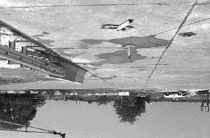
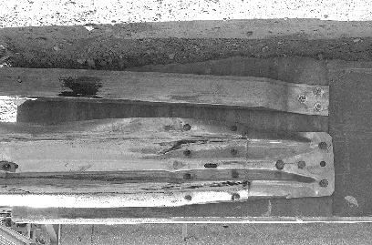
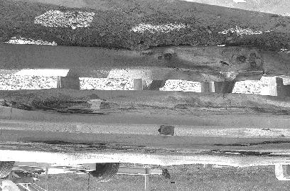
99 75 75 Figure 33. Installation after test
100 post 3, the rub rail was twisted. The spacing between the metal pipe and blockout and the concrete parapet was 45 mm before the test and after the test the pipe was leaning against the parapet and the spacing was 15 mm. The concrete parapet was pushed back 25 mm. Total length of contact of the vehicle with the transition and concrete parapet was 3.91 m. Vehicle Damage The vehicle sustained substantial damage as shown in figure 34. The upper and lower A-arms and frame rail were all severely damaged. Both left-side quarter panels were damaged and the left door had a gap (not measurable). The right door, front and rear rims, and the rear quarter panel sustained damage. Also damaged were the rear bumper and tailgate. The front bumper, grill, hood, radiator, fan, and cab were deformed. The windshield and the right, left, and rear glasses were shattered. Maximum exterior crush to the vehicle was 530 mm at the front bumper and 410 mm above the front bumper. Maximum deformation of the occupant compartment was 75 mm in the center floor pan area and 27 mm in the firewall area. Details can be found in appendix B, tables 35 and 36. Occupant Risk Factors In the longitudinal direction, the occupant impact velocity was 6.1 m/s at s, the highest s occupant ridedown acceleration was -6.1 g s from to s, and the maximum s average acceleration was -9.7 g s between and s. In the lateral direction, the occupant impact velocity was 7.7 m/s at s, the highest s occupant ridedown acceleration was 9.2 g s from to s, and the maximum s average was 11.9 g s between and s. These data and other pertinent information from the test are summarized in figure 35. Vehicle angular displacements are displayed in appendix D, figure 123. Vehicular accelerations versus time traces are presented in appendix E, figures 180 through 190. Assessment of Test Results As stated previously, the following NCHRP Report 350 safety evaluation criteria were used to evaluate this crash test:! Structural Adequacy A. Test article should contain and redirect the vehicle; the vehicle should not penetrate, underride, or override the installation although controlled lateral deflection of the test article is acceptable. Result: The vertical flared back transition contained and redirected the vehicle. The vehicle did not penetrate, underride, or override the installation. Maximum dynamic deflection was 0.17 m. 76


101 After being righted Figure 34. Vehicle after test
 Curb... Test Inertial... Dummy... Gross Static.")

 x-direction... y-direction... PHD (g s)... ASI... Max. 0.050-s Average (g's) x-direction... y-direction... z-direction... 101.0 24.8 75.7 5.2 6.1-7.")
... Post-Impact Behavior (during 1.0 s after impact) Max. Yaw Angle (deg)... Max. Pitch Angle (deg)... Max. Roll Angle (deg)... Figure 35.")
102 0.000 s s s s 78 General Information Test Agency... Test No.... Date... Test Article Type... Name or Manufacturer... Installation Length (m)... Material or Key Elements... Soil Type and Condition... Test Vehicle Type... Designation... Model... Mass (kg) Curb... Test Inertial... Dummy... Gross Static... Texas Transportation Institute /03/98 Transition Vertical Flared Back Transition 38.3 W-beam with W-beam Rub Rail & Steel Posts to Vertical Flared Back Parapet Standard Soil, Dry Production 2000P 1994 Chevrolet 2500 Pickup Truck Impact Conditions Speed (km/h)... Angle (deg)... Exit Conditions Speed (km/h)... Angle (deg)... Occupant Risk Values Impact Velocity (m/s) x-direction... y-direction... THIV (km/h)... Ridedown Accelerations (g's) x-direction... y-direction... PHD (g s)... ASI... Max s Average (g's) x-direction... y-direction... z-direction Test Article Deflections (m) Dynamic... Permanent... Vehicle Damage Exterior VDS... CDC... Maximum Exterior Vehicle Crush (mm)... Interior OCDI... Max. Occ. Compart. Deformation (mm)... Post-Impact Behavior (during 1.0 s after impact) Max. Yaw Angle (deg)... Max. Pitch Angle (deg)... Max. Roll Angle (deg)... Figure 35. Summary of results for the vertical flared back transition test, NCHRP Report 350 test LFQ4 11FLEK3 & 11LDEW3 530 LF
103 ! Occupant Risk D. Detached elements, fragments or other debris from the test article should not penetrate or show potential for penetrating the occupant compartment, or present an undue hazard to other traffic, pedestrians, or personnel in a work zone. Deformation of, or intrusions into, the occupant compartment that could cause serious injuries should not be permitted. Result: No detached elements or debris were present to penetrate or to show potential for penetrating the occupant compartment, or to present undue hazard to others in the area. Maximum deformation of the occupant compartment was 75 mm in the center floor pan area. F. The vehicle should remain upright during and after collision although moderate roll, pitching and yawing are acceptable. Result: After exiting the transition, the vehicle rolled one revolution and came to rest upright, 9.9 m toward traffic lanes.! Vehicle Trajectory K. After collision it is preferable that the vehicle s trajectory not intrude into adjacent traffic lanes. Result: The vehicle did intrude into adjacent traffic lanes. L. The occupant impact velocity in the longitudinal direction should not exceed 12 m/s and the occupant ridedown acceleration in the longitudinal direction should not exceed 20 G s. Result: Longitudinal occupant impact velocity was 6.1 m/s and longitudinal ridedown acceleration was -6.1 g s. M. The exit angle from the test article preferably should be less than 60 percent of the test impact angle, measured at time of vehicle loss of contact with the test device. Result: Exit angle at loss of contact was 5.2 degrees, which was less than 60 percent of the impact angle. The following supplemental evaluation factors and terminology were used for visual assessment of test results: 79
104 PASSENGER COMPARTMENT INTRUSION 1. Windshield Intrusion a. No windshield contact b. Windshield contact, no damage c. Windshield contact, no intrusion d. Device embedded in windshield, no significant intrusion e. Complete intrusion into passenger compartment f. Partial intrusion into passenger compartment 2. Body Panel Intrusion yes or no LOSS OF VEHICLE CONTROL 1. Physical loss of control 3. Perceived threat to other vehicles 2. Loss of windshield visibility 4. Debris on pavement PHYSICAL THREAT TO WORKERS OR OTHER VEHICLES 1. Harmful debris that could injure workers or others in the area 2. Harmful debris that could injure occupants in other vehicles No debris was present. VEHICLE AND DEVICE CONDITION 1. Vehicle Damage a. None b. Minor scrapes, scratches or dents c. Significant cosmetic dents 2. Windshield Damage a. None b. Minor chip or crack c. Broken, no interference with visibility d. Broken and shattered, visibility restricted but remained intact d. Major dents to grill and body panels e. Major structural damage e. Shattered, remained intact but partially dislodged f. Large portion removed g. Completely removed 3. Device Damage a. None b. Superficial c. Substantial, but can be straightened d. Substantial, replacement parts needed for repair e. Cannot be repaired 80
105 PENNSYLVANIA TRANSITION (NCHRP REPORT 350 TEST NO. 3-21) Test Conditions The test performed on the Pennsylvania transition corresponds to NCHRP Report 350 test designation The BARRIER VII simulation program was used to select the CIP for this test. The program indicated the CIP to be 2.0 m from the end of the concrete parapet. Test Article The Pennsylvania Guide Rail Transition (without drainage inlet) consists of 3810 mm of two nested 12-gauge W-beam guardrails blocked out from the end of the parapet using a 150-mmdiameter spacer tube followed by 3810 mm of single W-beam guardrail. In addition, the transition incorporates a flared-back C150 rub rail. The height of the W-beam guardrail used in this transition was approximately 790 mm from the pavement surface. The centerline height of the rub rail from the pavement surface was approximately 330 mm. TTI received numerous drawings from Pennsylvania DOT entitled Standard Bridge Parapet to Guide Rail Transition, BC-739M, Sheet 1 of 2, dated December 24, 1999, and Type 2 Strong Post Guide Rail, RC52M, dated September 30, Details for the moment slab constructed to support the concrete parapet were also received. TTI incorporated the details provided from these drawings to construct the field test installation for this project. TTI received all the hardware to construct this transition from Trinity Industries, Fort Worth, Texas. TTI constructed 5 m of Pennsylvania Standard Bridge Parapet from details provided to TTI by Pennsylvania DOT. The standard parapet constructed for this project was approximately 1070 mm in height and 440 mm in width at the base on the downstream end. At approximately 1802 mm from the end of the parapet, the parapet flared 10 degrees back away from the traffic side and transitioned to a height and width of approximately 810 mm, and 315 mm respectively, at the end of the parapet. The parapet was supported by a 330-mm-thick concrete moment slab. Vertical reinforcement in the parapet consisted of #16 enclosed stirrup bars located approximately 150 mm on centers. Longitudinal reinforcement in the parapet consisted of six #16 bars located in the lower portion of the parapet with four #19 bars located in the upper portion of the parapet. All reinforcement in the parapet was epoxy coated. A Type B Insert was purchased from Brocker Rebar Company, York, Pennsylvania, and was installed in the parapet approximately 1280 mm from the end of the parapet and at a centerline height of approximately 634 mm for anchoring the terminal connector to the parapet. Three 25-mm pipe sleeves were cast in the parapet approximately 1287 mm from the end of the parapet (centerline distance) and at a centerline height of approximately 330 mm. These pipe sleeves were used for anchoring the rub rail to the parapet with three 22-mm diameter A325 bolts. The rub rail bolts fastened completely through the parapet and a 175-mm x 175-mm x 12-mm thick plate on the field side of the parapet. 81
106 The moment slab constructed for the project was approximately 4.7 m by 6.6 m in plan and 330 mm thick. The slab was connected to an existing concrete runway slab located at our testing facility with 762-mm-long dowels located approximately 456 mm on centers. The parapet and slab were constructed so that the parapet was oriented approximately 10 degrees with the existing edge of runway. Top transverse reinforcement in the slab consisted of #19 hooked bars located approximately 152 mm on centers. Bottom transverse reinforcement in the slab consisted of #16 straight bars located approximately 305 mm on centers. Longitudinal reinforcement in the slab consisted of #13 straight bars located approximately 305 mm on centers in both the top and bottom layers in the slab with the exception of the distance between the second and third bars located from the field side edge of the slab. These bars were located approximately 152 mm apart. The parapet was anchored to the slab by #16 V-shaped bars that were cast in the slab and extended from the bottom layer of reinforcement in the slab upwards into the parapet. These bars were located approximately 150 mm on centers from the end of the parapet to a distance of approximately 4.3 m from the end. Beyond this distance these bars were located 300 mm on centers. The transition was attached to the concrete parapet with a 10-gauge W-beam terminal connector welded to a steel plate. The connector attached to the parapet using four 22-mm-diameter ASTM A307 bolts in the Type B Insert. The rub rails were attached to the parapet with three A325 bolts. All posts used in the transitions and length of need W-beam guardrail were W150x13.5 steel posts. The first four posts (posts 1 through 4) used in the transition were 2135 mm in length and embedded approximately 1355 mm below grade. The remaining posts (posts 5 through 15) were 1830 mm in length and embedded approximately 1030 mm below grade. The centerline of post 1 was located approximately 263 mm from the end of the concrete parapet. A 150-mm-diameter by 305- mm-long steel spacer tube attached to the nested W-beam guardrail and was located approximately 475 mm toward the terminal connector from post 1. From post 1 to post 7, the post spacing was approximately 475 mm. Posts were spaced approximately 952 mm apart from post 7 to 11. From post 11 to 15 (W-beam guardrail length of need), the post spacing was 1905 mm apart. A LET end treatment was used beyond the length of need to anchor the W-beam guardrail. The rub rail used for this project consisted of a two-piece rub rail mounted 330 mm from the pavement surface to its centerline. Both pieces of the rub rail were fabricated from C150x12 steel channel. Both pieces of the rub rail were spliced together at post 1 with a 10-mm-thick steel splice plate. From post 1, the rub rail was connected on each post and flared back at post 7 to the web of post 8 and was not attached. The nested W-beam guardrail and the rub rail (at post 1 through 7) were blocked out from the posts approximately 190 mm. Routed wood blockouts (150 mm x 200 mm x 565 mm) were used at posts 1 through 7. Standard routed wood blockouts (150 mm x 200 mm x 360 mm ) were used at posts 8 through 15. The rub rail and the nested W-beam guardrail were attached to each post using 16- mm-diameter A307 button head bolts. Detailed drawings are provided in figure 36. Photographs of the completed installation as tested are shown in figure
107 83 Figure 36. Details of the Pennsylvania transition installation for test
108 84 Figure 36. Details of the Pennsylvania transition installation for test (continued).
109 85 Figure 36. Details of the Pennsylvania transition installation for test (continued).
110 86 Figure 36. Details of the Pennsylvania transition installation for test (continued).
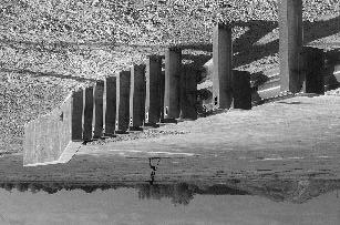
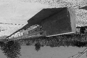
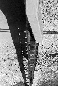
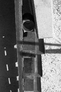
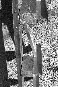
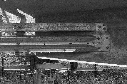
111 Figure 37. Pennsylvania transition prior to test
112 Soil and Weather Conditions The crash test was performed the morning of July 7, No rainfall was recorded for the 10 days prior to the test. Moisture content of the NCHRP Report 350 standard soil in which the transition was installed was 5.8 percent, 6.7 percent, and 7.6 percent at posts 1, 3, and 5, respectively. Weather conditions at the time of testing were as follows: temperature: 33EC; wind speed: 0 km/h; wind direction: 0 (vehicle was traveling in a westerly direction); relative humidity: 51 percent. Test Vehicle A 1996 Chevrolet 2500 pickup truck, shown in figure 38, was used for the crash test. Test inertia weight of the vehicle was 2000 kg, and its gross static weight was 2075 kg. The height to the lower edge of the vehicle front bumper was 390 mm and to the upper edge of the front bumper was 600 mm. Additional dimensions and information on the vehicle are given in appendix B, figure 85. Impact Description The left front corner of the bumper of the 2000-kg pickup truck impacted the transition 2.1 m from the end of the concrete parapet. The vehicle was traveling at a speed of km/h and an impact angle of 24.3 degrees. Shortly after impact, posts 4 and 5 moved. Post 3 moved at s, and at s post 6 moved. At s the left front tire contacted the rail element, and at s post 2 moved. Posts 1 and 7 moved at s and 0.31 s, respectively. The vehicle began to redirect at s. The right front wheel lost contact with the pavement surface at s, and by s the rear of the pickup truck contacted the rail element. The pickup truck became parallel with the transition at s and was traveling at a speed of 78.4 km/h. The right rear wheel lost contact with the pavement surface at s. At s the left front wheel lost contact with the concrete parapet. The left rear wheel lost contact with the concrete parapet at s. The vehicle lost contact with the transition at s and was traveling at a speed of 78.0 km/h and an exit angle of 13.7 degrees. The left rear wheel touched the pavement surface at s, and the left front at s. The vehicle remained upright and stable during the collision period and after loss of contact. Brakes on the vehicle were not applied and the vehicle yawed clockwise, subsequently coming to rest 64.0 m beyond impact and 25.9 m toward traffic lanes. Sequential photographs of the test period are shown in appendix C, figures 104 and


113 Figure 38. Vehicle before test
114 Damage to Test Article The Pennsylvania transition sustained minimal damage as shown in figure 39. Tire marks were on the face of the W-beam rail element and rub rail and both were deformed. The bolt on the rub rail at post 2 was bent and the bolt was pulled out of the rub rail at post 4. The spacer tube was crushed 28 mm. The space between the spacer tube and the concrete parapet was reduced 5 mm. No movement was noted in the end terminal. Maximum dynamic deflection of the W-beam rail element was 177 mm. Maximum permanent rail deformation of the W-beam rail element was 110 mm at post 1 and the rub rail was deformed 98 mm at post 2. The length of contact of the vehicle with the transition was 3.9 m. No apparent cracking was observed in the concrete parapet or slab. Vehicle Damage The vehicle sustained damage to the left front as shown in figure 40. Structural damage included the left front of the frame, left upper and lower A-arms, left tie rod end, stabilizer bar, floor pan and firewall. Also damaged were the front bumper, grill, fan, radiator, left front and rear quarter panels, left door and window, left front and rear tires and wheel rims. The windshield sustained stress cracks. Maximum exterior crush of the vehicle was 440 mm at the left front corner at bumper height. The maximum deformation of the occupant compartment was 117 mm in the center of the floor pan area. Exterior vehicle crush and occupant compartment measurements are shown in appendix B, tables 37 and 38. Occupant Risk Factors In the longitudinal direction, occupant impact velocity was 5.5 m/s at s, maximum s ridedown acceleration was -8.5 g s from to s, and the maximum s average was -8.8 g s between and s. In the lateral direction, the occupant impact velocity was 7.4 m/s at s, the highest s occupant ridedown acceleration was 7.8 g s from to s, and the maximum s average was 12.8 g s between and s. These data and other information pertinent to the test are presented in figure 41. Vehicle angular displacements are presented in appendix D, figure 124, and accelerations versus time traces are shown in appendix E, figures 191 through 201. Assessment of Test Results test: The following NCHRP Report 350 safety evaluation criteria were used to evaluate this crash 90
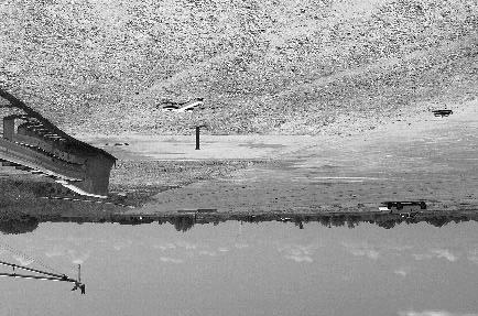
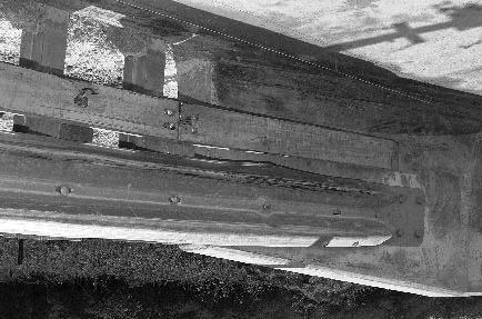
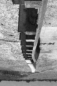
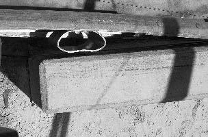
115 Figure 39. Installation after test


116 Figure 40. Vehicle after test
 Curb... Test Inertial... Dummy... Gross Static.")
.")
 x-direction... y-direction... PHD (g s)... ASI... Max. 0.050-s Average (g's) x-direction... y-direction... z-direction... 100.9 24.3 78.0 13.")
... Post-Impact Behavior (during 1.0 s after impact) Max. Yaw Angle (deg)... Max. Pitch Angle (deg)... Max. Roll Angle (deg).")
117 0.000 s s s s 93 General Information Test Agency... Test No.... Date... Test Article Type... Name... Installation Length (m)... Material or Key Elements. Soil Type and Condition. Test Vehicle Type... Designation... Model... Mass (kg) Curb... Test Inertial... Dummy... Gross Static... Texas Transportation Institute /07/00 Transition Pennsylvania Transition 31.0 W-beam Rail with Rub Rail Attached to Concrete Parapet Standard Soil, Dry Production 2000P 1996 Chevrolet 2500 Pickup Truck Impact Conditions Speed (km/h)... Angle (deg)... Exit Conditions Speed (km/h)... Angle (deg)... Occupant Risk Values Impact Velocity (m/s) x-direction... y-direction... THIV (km/h)... Ridedown Accelerations (g's) x-direction... y-direction... PHD (g s)... ASI... Max s Average (g's) x-direction... y-direction... z-direction Test Article Deflections (m) Dynamic... Permanent... Vehicle Damage Exterior VDS... CDC... Maximum Exterior Vehicle Crush (mm)... Interior OCDI... Max. Occ. Compart. Deformation (mm)... Post-Impact Behavior (during 1.0 s after impact) Max. Yaw Angle (deg)... Max. Pitch Angle (deg)... Max. Roll Angle (deg) LFQ4 11FLEK3 & 11LDEW3 440 LF Figure 41. Summary of results for the Pennsylvania Transition test, NCHRP Report 350 test 3-21.
118 ! Structural Adequacy A. Test article should contain and redirect the vehicle; the vehicle should not penetrate, underride, or override the installation although controlled lateral deflection of the test article is acceptable. Result: The Pennsylvania transition contained and redirected the 2000P vehicle. The vehicle did not penetrate, underride, or override the installation. Maximum lateral deflection was 177 mm.! Occupant Risk D. Detached elements, fragments or other debris from the test article should not penetrate or show potential for penetrating the occupant compartment, or present an undue hazard to other traffic, pedestrians, or personnel in a work zone. Deformation of, or intrusions into, the occupant compartment that could cause serious injuries should not be permitted. Result: No detached elements, fragments, or other debris were present to penetrate or to show potential for penetrating the occupant compartment, or to present undue hazard to others in the area. Maximum deformation of the occupant compartment was 117 mm in the center floor pan area and was judged to not cause serious injury. F. The vehicle should remain upright during and after collision although moderate roll, pitching and yawing are acceptable. Result: The 2000P vehicle remained upright during and after the collision period.! Vehicle Trajectory K. After collision it is preferable that the vehicle s trajectory not intrude into adjacent traffic lanes. Result: The 2000P vehicle came to rest 25.9 m toward traffic lanes, which indicated intrusion into adjacent traffic lanes. L. The occupant impact velocity in the longitudinal direction should not exceed 12 m/s and the occupant ridedown acceleration in the longitudinal direction should not exceed 20 G s. Result: Longitudinal occupant impact velocity was 5.5 m/s and occupant ridedown acceleration was -8.5 g s. 94
119 M. The exit angle from the test article preferably should be less than 60 percent of the test impact angle, measured at time of vehicle loss of contact with the test device. Result: Exit angle at loss of contact with the transition was 13.7 degrees, which was 56 percent of the impact angle. The following supplemental evaluation factors and terminology were used for visual assessment of test results: PASSENGER COMPARTMENT INTRUSION 1. Windshield Intrusion a. No windshield contact b. Windshield contact, no damage c. Windshield contact, no intrusion d. Device embedded in windshield, no significant intrusion e. Complete intrusion into passenger compartment f. Partial intrusion into passenger compartment 2. Body Panel Intrusion yes or no LOSS OF VEHICLE CONTROL 1. Physical loss of control 3. Perceived threat to other vehicles 2. Loss of windshield visibility 4. Debris on pavement After loss of contact with the transition, the vehicle came to rest 25.9 m laterally from the traffic face of the rail, which indicated intrusion into adjacent traffic lanes and a perceived threat to other vehicles in those lanes. PHYSICAL THREAT TO WORKERS OR OTHER VEHICLES 1. Harmful debris that could injure workers or others in the area 2. Harmful debris that could injure occupants in other vehicles No debris was present to threaten workers or other vehicles. VEHICLE AND DEVICE CONDITION 1. Vehicle Damage a. None b. Minor scrapes, scratches or dents c. Significant cosmetic dents d. Major dents to grill and body panels e. Major structural damage 95
120 2. Windshield Damage a. None b. Minor chip or crack c. Broken, no interference with visibility d. Broken and shattered, visibility restricted but remained intact e. Shattered, remained intact but partially dislodged f. Large portion removed g. Completely removed 3. Device Damage a. None b. Superficial c. Substantial, but can be straightened d. Substantial, replacement parts needed for repair e. Cannot be repaired 96
121 NEBRASKA TRANSITION (NCHRP REPORT 350 TEST NO. 3-21) Test Conditions The test performed on the Nebraska transition corresponds to NCHRP Report 350 test designation The BARRIER VII simulation program was used to select the CIP for this test. The program indicated the CIP to be 1.8 m from the end of the concrete parapet. Test Article The Nebraska thrie beam transition consists of 3810 mm of two nested 12-gauge thrie beam guardrails followed by a 12-gauge W-beam to 12-gauge thrie beam transition piece. This transition piece connected to 7.62 m of W-beam guardrail that was anchored with a LET End Treatment. The height of the thrie beam transition was approximately 804 mm. The height of the W-beam guardrail was approximately 706 mm. TTI received AutoCAD drawing details for this transition from Dr. Ron Faller with Midwest Roadside Safety Facility in September TTI received additional drawings from FHWA Eastern Federal Lands Highway Division (EFLHD) for the concrete parapet supported by two drilled shafts in February TTI constructed 2.23 m of concrete parapet from details provided to TTI by EFLHD. This parapet was 835 mm in height and 350 mm wide. At the guardrail transition end, the parapet tapered from 350 mm wide to 150 mm over a distance of 630 mm. The parapet was supported by a 600-mm 650-mm footing that was supported by two 450-mm-diameter drilled shafts spaced approximately 1.35 m apart. These drilled shafts extended 3.0 m below the footing, which was constructed flush with grade. Reinforcement in the parapet consisted of #19 U shaped and straight vertical bars at 150 mm on centers on each face of the parapet. Horizontal reinforcement in the parapet consisted of eight sets of overlapping #13 U and V shaped bars equally spaced. Reinforcement in the concrete footing consisted of #13 closed stirrups at 150 mm on centers. These stirrups were not closed in the areas of the vertical reinforcement for the drilled shafts extending into the footing. Longitudinal reinforcement in the footing consisted of 10 #16 bars inside the stirrups. Reinforcement for the drilled shafts consisted of 12 #19 bars equally spaced inside #13 spiral reinforcement. The outside diameter of the spiral reinforcement was approximately 300 mm. The #13 spiral reinforcement was constructed with a 45- mm pitch. The average compressive strength of the parapet and footing concrete measured 31 MPa (4500 psi) and 32 MPa (4636 psi), respectively. All reinforcement used in the parapet was bare steel (not epoxy coated) and had an approximate yield strength of 420 MPa (60 ksi). Details of the parapet are shown on page 1 of figure 42. The nested thrie beam transition was attached to the concrete parapet with a 10-gauge thrie beam terminal connector attached to the parapet using five 22-mm diameter ASTM A325 bolts. The centerline of post 1 was located approximately 1220 mm from the end of the parapet. The Nebraska thrie beam transition design incorporates a special hidden post design using a TS steel tube that attaches to the end of the parapet and is supported by post 1. This steel tube supports a 97
122 98 Figure 42. Details of the Nebraska thrie beam transition installation for test
123 99 Figure 42. Details of the Nebraska thrie beam transition installation for test (continued).
124 100 Figure 42. Details of the Nebraska thrie beam transition installation for test (continued).
125 150-mm 200-mm 400-mm wood block that is located 298 mm from the end of the parapet, which, in turn, supports the nested thrie beam guardrail without the use of an embedded post at this location. A 112-mm 250-mm 13-mm thick A36 steel plate was welded to the end of the tube and was used to attach the steel tube to post 1 using two 22-mm-diameter A307 bolts that bolted through the plate and web of post 1. The steel tube is supported at the parapet by a steel plate bracket fabricated from 13-mm-thick plate with a 160-mm-long piece of TS steel tube welded to the plate bracket. The TS steel tube supporting the hidden post blockout fits inside the TS tube welded to the bracket and is bolted with two 19-mm-diameter A307 bolts, 170 mm in length. The steel bracket was attached to the parapet with two 16-mmdiameter A325 mechanical anchors located on the sloped surface of the parapet. In addition, the bracket was secured with two chemically anchored ASTM 193 Grade B7 fully threaded rods embedded 300 mm at the end of the parapet. These bolts projected out from the end of the parapet approximately 55 mm. Posts 1 through 5 were spaced approximately 952 mm apart. Between posts 5 and 9 the post spacing was approximately 1905 mm. The posts were spaced approximately 1905 mm apart in the LET end anchorage system. Posts 1 and 2 were W steel posts, approximately 2591 mm in length, and embedded approximately 1838 mm below grade. Posts 3 through 6 were W steel posts, and 2134 mm in length. Posts 3, 4, 5, and 6 were embedded below grade approximately 1381 mm, 1355 mm, 1406 mm, and 1406 mm, respectively. Posts 7 through 9 were W steel posts, approximately 1830 mm in length, and embedded approximately 1100 mm below grade. Wood blockouts were used at posts 1 through 13. Wood blockouts were not required for posts 14 and 15. For posts 1 through 4, 150-mm 200-mm 457-mm long wood blocks were used between the guardrail and posts. At posts 5 and 6, 150-mm 200-mm 356-mm long wood blockouts were used between the guardrail and posts. For posts 7 through 9, 150-mm 200-mm 356-mm routed wood blockouts were used between the guardrail and posts. Posts 1 4 used two 16- mm-diameter by 255-mm-long guardrail bolts and nuts to secure the guardrail and blockout to each post. In addition, posts 5 9 used one 16-mm-diameter by 255-mm-long guardrail bolt and nut to secure the guardrail and blockout to each post. Longer 16-mm-diameter bolts (460 mm) were used for the wood posts in the LET end anchorage system. All posts were embedded in compacted NCHRP Report 350 standard soil with the moisture content within 4% +/- of optimum moisture content of the material. Additional detail drawings are shown on pages 2 and 3 of figure 42. Photographs of the completed test installation are shown in figure 43. Soil and Weather Conditions The crash test was performed the morning of May 16, Seven days prior to the test 38 mm of rainfall was recorded, and four days prior to the test 10 mm of rainfall was recorded. Soil moisture content was 5.6 percent, 7.0 percent, and 8.6 percent at posts 1, 3, and 5, respectively. Weather conditions at the time of testing were as follows: wind speed: 24 km/h; wind direction: 15 degrees with respect to the vehicle (vehicle was traveling in a southeasterly direction); temperature: 32EC; relative humidity: 55 percent. 101


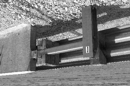
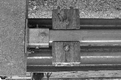
126 102 Figure 43. Nebraska thrie beam transition prior to test
127 Test Vehicle A 1995 Chevrolet 2500 pickup truck, shown in figure 44, was used for the crash test. Test inertia weight of the vehicle was 2000 kg, and its gross static weight was 2075 kg. The height to the lower edge of the vehicle front bumper was 370 mm and to the upper edge of the front bumper was 590 mm. Additional dimensions and information on the vehicle are given in appendix B, figure 86. Impact Description The 2000P vehicle traveling at 99.6 km/h impacted the transition 1.93 m from the end of the parapet at an impact angle of 24.6 degrees. Shortly after impact, posts 1 and 2 moved. At s the left front wheel steered away from the rail and the vehicle began to redirect. At s post 3 moved. The left front tire was traveling parallel with the rail at s and began to angle under the rail element at s. At s movement was noted in the concrete parapet and at s the left front tire contacted the end of the parapet. The dummy s head contacted the door glass at s, but the glass did not break. The vehicle became parallel with the rail at s and was traveling at a speed of 8l.6 km/h. The left rear of the vehicle impacted the rail at s. At s the vehicle lost contact with the transition and was traveling 78.3 km/h and an exit angle of 6.8 degrees. As the vehicle exited the transition both rear wheels were airborne. The left rear tire touched ground at s. Brakes on the vehicle were applied at 1.75 s after impact, the vehicle yawed counterclockwise, and subsequently came to rest 75 m downstream from impact and 6 m forward of the front face of the transition. Sequential photographs of the test period are shown in appendix C, figures 106 and 107. Damage to Test Article The Nebraska thrie beam transition sustained minimal damage as shown in figure 45. No movement was noted in the end terminal. Posts 4 and 5 were disturbed, post 3 moved rearward 4 mm, and post 2 was pushed rearward 20 mm. The corner of the blockout at post 1 was missing and the post was pushed back 15 mm. The pipe spacer between the parapet and rail element was crushed 25 mm and the parapet base was disturbed 2 mm. Tire marks were on the flare of the parapet and cracks in the end of the parapet radiated from the bolts connecting the thrie beam. Length of contact of the vehicle with the transition was 3.07 m. Maximum dynamic deflection of the rail element during the test was 82 mm and maximum permanent deformation was 24 mm, both occurring at post


128 Figure 44. Vehicle before test

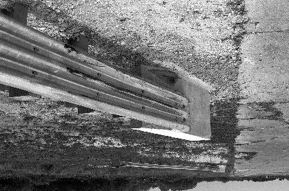

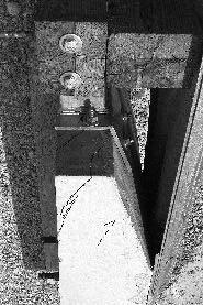
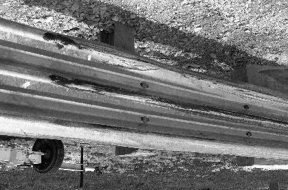
129 105 Figure 45. Installation after test
130 Vehicle Damage Moderate damage was imparted to the 2000P vehicle as shown in figure 46. The following vehicle components received structural damage: the frame at the left front, steering arm, stabilizer bar, left side rod ends, left upper and lower A-arms, and left front spindle, rotor and tire. Also damaged were the front bumper, fan, radiator, left front quarter-panel, left door, left side of the bed, and the left rear rim. The floor pan and firewall were deformed and the seam where the floor pan and firewall connect were separated. Maximum exterior crush to the left front corner was 400 mm. Maximum interior deformation was 129 mm at the left side floor pan area. Exterior vehicle crush and occupant compartment measurements are shown in appendix B, tables 39 and 40. Occupant Risk Factors In the longitudinal direction, occupant impact velocity was 5.0 m/s at s, maximum s ridedown acceleration was g s from to s, and the maximum s average was -8.2 g s between and s. In the lateral direction, the occupant impact velocity was 8.1 m/s at s, the highest s occupant ridedown acceleration was 11.9 g s from to s, and the maximum s average was 12.5 g s between and s. These data and other information pertinent to the test are presented in figure 47. Vehicle angular displacements are presented in appendix D, figure 125, and accelerations versus time traces are shown in appendix E, figures 202 through 212. Assessment of Test Results test: The following NCHRP Report 350 safety evaluation criteria were used to evaluate this crash! Structural Adequacy i. Test article should contain and redirect the vehicle; the vehicle should not penetrate, underride, or override the installation although controlled lateral deflection of the test article is acceptable. Result: The Nebraska thrie beam transition contained and redirected the vehicle with minimal deformation of the rail element. The 2000P vehicle did not penetrate, underride, or override the installation.! Occupant Risk D. Detached elements, fragments or other debris from the test article should not penetrate or show potential for penetrating the occupant compartment, or 106


131 Figure 46. Vehicle after test
 Curb... Test Inertial... Dummy... Gross Static.")
.")
 x-direction... y-direction... PHD (g s)... ASI... Max. 0.050-s Average (g's) x-direction... y-direction... z-direction... 99.6 24.6 78.3 6.8 5.")
... Post-Impact Behavior (during 1.0 s after impact) Max. Yaw Angle (deg)... Max. Pitch Angle (deg)... Max. Roll Angle (deg).")
132 0.000 s s s s 108 General Information Test Agency... Test No.... Date... Test Article Type... Name... Installation Length (m)... Material or Key Elements. Soil Type and Condition. Test Vehicle Type... Designation... Model... Mass (kg) Curb... Test Inertial... Dummy... Gross Static... Texas Transportation Institute /17/00 Transition Nebraska Thrie Beam Transition 22.2 Nested Thrie Beam on Steel Posts with Wood Blockouts Standard Soil, Dry Production 2000P 1995 Chevrolet 2500 Pickup Truck Impact Conditions Speed (km/h)... Angle (deg)... Exit Conditions Speed (km/h)... Angle (deg)... Occupant Risk Values Impact Velocity (m/s) x-direction... y-direction... THIV (km/h)... Ridedown Accelerations (g's) x-direction... y-direction... PHD (g s)... ASI... Max s Average (g's) x-direction... y-direction... z-direction Test Article Deflections (m) Dynamic... Permanent... Vehicle Damage Exterior VDS... CDC... Maximum Exterior Vehicle Crush (mm)... Interior OCDI... Max. Occ. Compart. Deformation (mm)... Post-Impact Behavior (during 1.0 s after impact) Max. Yaw Angle (deg)... Max. Pitch Angle (deg)... Max. Roll Angle (deg) LFQ4 11FLEK3 & 11LDEW3 400 FS Figure 47. Summary of results for Nebraska Transition test, NCHRP Report 350 test 3-21.
133 present an undue hazard to other traffic, pedestrians, or personnel in a work zone. Deformation of, or intrusions into, the occupant compartment that could cause serious injuries should not be permitted. Result: No detached elements, fragments, or other debris were present to penetrate or to show potential for penetrating the occupant compartment, or to present undue hazard to others in the area. The floor pan and firewall were deformed and the seam where the floor pan meets the firewall was separated. Maximum occupant compartment deformation was 129 mm and damage to the interior was judged to not cause serious injury. F. The vehicle should remain upright during and after collision although moderate roll, pitching and yawing are acceptable. Result: The vehicle remained upright during and after the collision period.! Vehicle Trajectory K. After collision it is preferable that the vehicle s trajectory not intrude into adjacent traffic lanes. Result: Intrusion into adjacent traffic lanes was minimal, i.e., the vehicle came to rest 6 m forward from the face of the transition. L. The occupant impact velocity in the longitudinal direction should not exceed 12 m/s and the occupant ridedown acceleration in the longitudinal direction should not exceed 20 G s. Result: Longitudinal occupant impact velocity was 5.0 m/s and longitudinal ridedown acceleration was g s. M. The exit angle from the test article preferably should be less than 60 percent of the test impact angle, measured at time of vehicle loss of contact with the test device. Result: Exit angle at loss of contact was 6.8 degrees, which was 28 percent of the impact angle. The following supplemental evaluation factors and terminology were used for visual assessment of test results: 109
134 PASSENGER COMPARTMENT INTRUSION 1. Windshield Intrusion a. No windshield contact b. Windshield contact, no damage c. Windshield contact, no intrusion d. Device embedded in windshield, no significant intrusion e. Complete intrusion into passenger compartment f. Partial intrusion into passenger compartment 2. Body Panel Intrusion yes or no LOSS OF VEHICLE CONTROL 1. Physical loss of control 3. Perceived threat to other vehicles 2. Loss of windshield visibility 4. Debris on pavement PHYSICAL THREAT TO WORKERS OR OTHER VEHICLES 1. Harmful debris that could injure workers or others in the area 2. Harmful debris that could injure occupants in other vehicles No debris present. VEHICLE AND DEVICE CONDITION 1. Vehicle Damage a. None b. Minor scrapes, scratches or dents c. Significant cosmetic dents 2. Windshield Damage a. None b. Minor chip or crack c. Broken, no interference with visibility d. Broken and shattered, visibility restricted but remained intact d. Major dents to grill and body panels e. Major structural damage e. Shattered, remained intact but partially dislodged f. Large portion removed g. Completely removed 3. Device Damage a. None b. Superficial (rail element) c. Substantial, but can be straightened d. Substantial, replacement parts needed for repair (parapet) e. Cannot be repaired 110
135 CONNECTICUT TRANSITION (NCHRP REPORT 350 TEST NO. 3-21) Test Conditions NCHRP Report 350 test designation 3-21 was performed on the Connecticut transition. The BARRIER VII program indicated the CIP to be 2.0 m from the end of the concrete parapet. Test Article The Connecticut R-B 350 guiderail transition consists of 3810 mm of two nested W-beam guardrails blocked out from the end of the parapet using a 150-mm-diameter spacer pipe followed by 3810 mm of single W-beam guardrail. In addition, the transition incorporates a flared-back C150 rubrail and a 100-mm-high asphalt curb. The height of the W-beam guardrail used in this transition was approximately 706 mm from the pavement surface. The height of the rubrail from the pavement surface was approximately 305 mm. TTI received a drawing from Connecticut DOT entitled Standard R-B 350 Bridge Attachment, Drawing Number M TTI incorporated the details provided from this drawing to construct the field test installation for this project. TTI received all the hardware to construct this transition from Trinity Industries, Fort Worth, Texas. TTI constructed 5 m of Connecticut Jersey shape barrier from details provided to TTI by ConnDOT. This barrier was 815 mm in height and 580 mm in width at the base and transitioned to 300 mm in width at the top of the parapet. The parapet was anchored below grade by a 580-mm-wide footing embedded 1895 mm below grade and extended the full length of the parapet. Vertical reinforcement for the parapet consisted of #16 U-Shaped Bars spaced at 300 mm on centers. Longitudinal reinforcement in the parapet consisted of eight #16 longitudinal reinforcing bars. The end of the parapet was constructed with a 2.5(H) to 1.0(V) taper at the top. The concrete used to construct the concrete parapet had an average concrete compressive strength of 4483 psi 30 days after construction. The transition was attached to the concrete parapet with a 10-gauge W-beam terminal connector attached to the parapet using five 22-mm-diameter ASTM A449 fully threaded rods. These threaded rods were 300 mm long and were chemically anchored inside 25-mm-diameter holes drilled into the parapet. The end of the terminal connector was located approximately 2150 mm from the end of the parapet. The rubrail was attached to the parapet using three 16-mm-diameter ASTM A449 fully threaded rods. These threaded rods used for the rubrail were 150 mm long and were chemically anchored inside 19-mm-diameter holes drilled into the parapet. The end of the rubrail was located approximately 1291 mm from the end of the parapet. The first two posts (posts 1 and 2) used in the transition were two W200x19 steel posts. These posts were each 2290 mm in length. Posts 1 and 2 were embedded approximately 1560 mm below grade. The remaining posts used in the transition (posts 3 through 9) and the posts used for the guardrail length of need were W150x13 steel posts, 1830 mm in length. These posts were embedded 111
136 approximately 1100 mm below grade. Post 1 was located approximately 300 mm from the end of the concrete parapet. Between posts 1 and 5, the posts were spaced approximately 476 mm apart. Between posts 5 and 9, the posts were spaced approximately 952 mm apart. Between posts 9 and 13 (W-beam guardrail length of need), the posts were spaced 1905 mm apart. A LET guardrail end treatment was used beyond the length of need to anchor and protect the end of the W-beam guardrail. The W-beam guardrail was blocked out from the concrete parapet at approximately 145 mm from the end of the parapet with a 150 mm diameter, schedule 40 steel spacer tube, 230 mm in length. The W-beam guardrail was blocked out from the steel posts with 150 mm x 200 mm routed wood blocks, 360 mm in length. The rubrail used consisted of a two-piece rubrail mounted 230 mm from the pavement surface to the rubrail centerline. The smaller rubrail piece, which connected to the concrete parapet, was fabricated from C150x12 steel channel approximately 1595 mm in length. This portion of the rubrail extended from the connection of the concrete parapet to post 1. At post 1, the rubrail was spliced using a bent plate rubrail that extended from post 1 to the field side face of post 6. The rubrail was blocked out from the concrete parapet at approximately 134 mm from the end of the parapet with a sloped 114-mm-long by 90-mm-wide wood block. This block was sloped to match the shape of the concrete parapet. At posts 1 through 4, 180-mm-long by 100-mm-wide wood blocks were used to block out the rubrail from the steel posts. The thickness of these blockouts varied from 108 mm to 25 mm between posts 1 through 4 due to the flaring back of the rubrail. No blockout was required at post 5. The rubrail flared behind post 6 and was not attached. An asphalt curb was constructed as part of this transition installation. The curb was 100 mm in height, 180 mm wide at the base, and 75 mm at the top. The curb was constructed with an 80-mm sloped face. The base of the curb was constructed flush with the base of the parapet and sloped toward the roadway on a 20(H) to 1(V) slope until the face of the curb was even with the face of the W-beam guardrail. The face of the curb remained even with the guardrail for the remainder of the curb installation. Detailed drawings are provided in figure 48. Photographs of the completed installation as tested are shown in figure 49. Soil and Weather Conditions The crash test was performed the morning of April 6, Eight days before the test 10 mm of rainfall was recorded and a total of 33 mm of rainfall was recorded four days prior to the test. Moisture content of the NCHRP Report 350 standard soil in which the transition was installed was 5.5 percent, 9.0 percent, and 9.8 percent at posts 1, 3, and 5, respectively. Weather conditions at the time of testing were as follows: wind speed: 11 km/h; wind direction: 85 degrees with respect to the vehicle (vehicle was traveling in an easterly direction); temperature: 22EC; relative humidity: 55 percent. 112
137 113 Figure 48. Details of the Connecticut transition installation for test
138 114 Figure 48. Details of the Connecticut transition installation for test (continued).
139 115 Figure 48. Details of the Connecticut transition installation for test (continued).
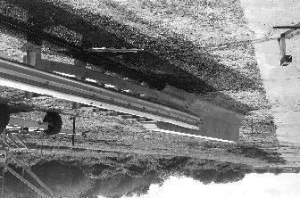
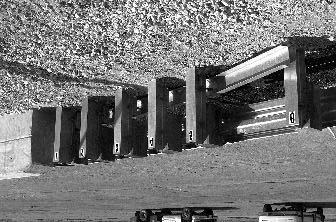
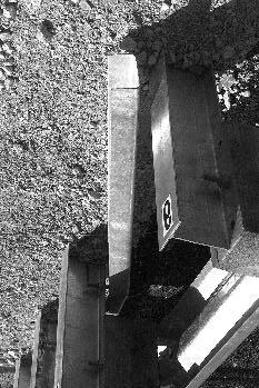
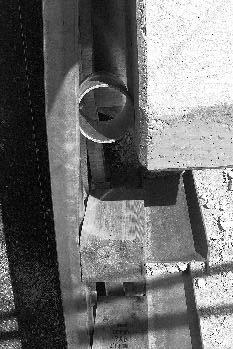
140 Figure 49. Connecticut transition prior to test
141 Test Vehicle A 1995 Chevrolet 2500 pickup truck, shown in figure 50, was used for the crash test. Test inertia weight of the vehicle was 2000 kg, and its gross static weight was 2075 kg. The height to the lower edge of the vehicle front bumper was 370 mm and to the upper edge of the front bumper was 590 mm. Additional dimensions and information on the vehicle are given in appendix B, figure 87. Impact Description The 2000P pickup truck, traveling at km/h, impacted the Connecticut transition 1.96 m from the end of the concrete parapet at a 25.6-degree angle. Shortly after impact, the left front tire contacted the rubrail. The left and right front wheels steered away from the rail element at s and the vehicle began to redirect at s. The dummy contacted the driver s side window, and the window glass shattered at s. By s, the right front tire lost contact with the ground, and by s, the rear left side of the vehicle contacted the rail element. At s, the vehicle was traveling parallel with the transition at a speed of 80.3 km/h, and at s, the right rear tire lost contact with the ground. The left rear tire lost contact with the ground at s. The vehicle lost contact with the transition at s, and was traveling at a speed of 77.0 km/h and an exit angle of 3.7 degrees. The left rear, right front, and right rear tires returned to the ground surface at s, s, and s, respectively. Brakes on the vehicle were applied at 1.55 s, the vehicle yawed clockwise and subsequently came to rest 61.7 m down from impact and 27.4 m laterally from the traffic face of the rail. Sequential photographs of the test period are shown in appendix C, figures 108 and 109. Damage to Test Article Moderate damage was imparted to the transition as shown in figure 51. Tire marks were on the face of the W-beam rail element and rub rail and both were deformed. The blockouts at posts 2 and 3 were rotated and the blockout at post 4 was fractured on one corner. The pipe insert was crushed 10 mm. The lower bolt on the connection to the parapet was partially pulled out. No movement was noted in the end terminal. Maximum dynamic deflection of the W-beam rail element was 77 mm. Maximum permanent rail deformation of the W-beam rail element was 68 mm at post 2 and the rubrail was deformed 45 mm at post 2. The length of contact with the transition was 2.9 m. 117


142 Figure 50. Vehicle before test
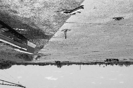
143 Figure 51. Installation after test
144 Vehicle Damage The vehicle sustained structural damage to the left front as shown in figure 52. Structural damage included the left front of the frame, left upper and lower A-arms, left inner and outer tie rods, steering arm, stabilizer bar, floor pan, and firewall. Also damaged were the front bumper, hood, grill, fan, radiator, left front quarter panel, left door, left rear quarter panel, and the left front tire and wheel rim. The windshield sustained stress cracks. Maximum exterior crush of the vehicle was 430 mm at the left front corner at bumper height. The maximum deformation of the occupant compartment was 130 mm in the center floor pan area and 124 mm in the center firewall area. Exterior vehicle crush and occupant compartment measurements are shown in appendix B, tables 41 and 42. Occupant Risk Factors In the longitudinal direction, occupant impact velocity was 4.9 m/s at s, maximum s ridedown acceleration was g s from to s, and the maximum s average was g s between and s. In the lateral direction, the occupant impact velocity was 7.0 m/s at s, the highest s occupant ridedown acceleration was 17.2 g s from to s, and the maximum s average was 12.6 g s between and s. These data and other information pertinent to the test are presented in figure 53. Vehicle angular displacements are presented in appendix D, figure 126, and accelerations versus time traces are shown in appendix E, figures 213 through 223. Assessment of Test Results test: The following NCHRP Report 350 safety evaluation criteria were used to evaluate this crash! Structural Adequacy A. Test article should contain and redirect the vehicle; the vehicle should not penetrate, underride, or override the installation although controlled lateral deflection of the test article is acceptable. Result: The Connecticut transition contained and redirected the 2000P vehicle. The vehicle did not penetrate, underride, or override the installation. Maximum lateral deflection was 77 mm.! Occupant Risk D. Detached elements, fragments or other debris from the test article should not penetrate or show potential for penetrating the occupant compartment, or present an undue hazard to other traffic, pedestrians, or personnel in a work zone. Deformation of, or intrusions into, the occupant compartment that could cause serious injuries should not be permitted. 120


145 Figure 52. Vehicle after test
 Curb... Test Inertial... Dummy... Gross Static.")

 x-direction... y-direction... PHD (g s)... ASI... Max. 0.050-s Average (g's) x-direction... y-direction... z-direction... 100.8 25.6 77.0 3.7 4.")
... Post-Impact Behavior (during 1.0 s after impact) Max. Yaw Angle (deg)... Max. Pitch Angle (deg)... Max. Roll Angle (deg).")
146 0.000 s s s s 122 General Information Test Agency... Test No.... Date... Test Article Type... Name... Installation Length (m)... Material or Key Elements. Soil Type and Condition. Test Vehicle Type... Designation... Model... Mass (kg) Curb... Test Inertial... Dummy... Gross Static... Texas Transportation Institute /06/00 Transition Connecticut Transition 26.7 W-beam Rail with Rubrail Attached to Connecticut Jersey Shape Parapet Standard Soil, Dry Production 2000P 1995 Chevrolet 2500 Pickup Truck Impact Conditions Speed (km/h)... Angle (deg)... Exit Conditions Speed (km/h)... Angle (deg)... Occupant Risk Values Impact Velocity (m/s) x-direction... y-direction... THIV (km/h)... Ridedown Accelerations (g's) x-direction... y-direction... PHD (g s)... ASI... Max s Average (g's) x-direction... y-direction... z-direction Test Article Deflections (m) Dynamic... Permanent... Vehicle Damage Exterior VDS... CDC... Maximum Exterior Vehicle Crush (mm)... Interior OCDI... Max. Occ. Compart. Deformation (mm)... Post-Impact Behavior (during 1.0 s after impact) Max. Yaw Angle (deg)... Max. Pitch Angle (deg)... Max. Roll Angle (deg) LFQ4 11FLEK3 & 11LDEW3 430 LF Figure 53. Summary of results for the Connecticut Transition test, NCHRP Report 350 test 3-21.
147 Result: No detached elements, fragments, or other debris were present to penetrate or to show potential for penetrating the occupant compartment, or to present undue hazard to others in the area. Maximum deformation of the occupant compartment was 130 mm in the center floor pan area and was judged to not cause serious injury. F. The vehicle should remain upright during and after collision although moderate roll, pitching and yawing are acceptable. Result: The 2000P vehicle remained upright during and after the collision period.! Vehicle Trajectory K. After collision it is preferable that the vehicle s trajectory not intrude into adjacent traffic lanes. Result: The 2000P vehicle came to rest 27.4 m toward traffic lanes, which indicated intrusion into adjacent traffic lanes. L. The occupant impact velocity in the longitudinal direction should not exceed 12 m/s and the occupant ridedown acceleration in the longitudinal direction should not exceed 20 G s. Result: Longitudinal occupant impact velocity was 4.9 m/s and occupant ridedown acceleration was g s. M. The exit angle from the test article preferably should be less than 60 percent of the test impact angle, measured at time of vehicle loss of contact with the test device. Result: Exit angle at loss of contact with the transition was 3.7 degrees, which was 14 percent of the impact angle. The following supplemental evaluation factors and terminology were used for visual assessment of test results: PASSENGER COMPARTMENT INTRUSION 1. Windshield Intrusion a. No windshield contact b. Windshield contact, no damage c. Windshield contact, no intrusion d. Device embedded in windshield, no significant intrusion e. Complete intrusion into passenger compartment f. Partial intrusion into passenger compartment 2. Body Panel Intrusion yes or no 123
148 LOSS OF VEHICLE CONTROL 1. Physical loss of control 3. Perceived threat to other vehicles 2. Loss of windshield visibility 4. Debris on pavement After loss of contact with the transition, the vehicle came to rest 27.4 m laterally from the traffic face of the rail, which indicated intrusion into adjacent traffic lanes and perceived threat to other vehicles in those lanes. PHYSICAL THREAT TO WORKERS OR OTHER VEHICLES 1. Harmful debris that could injure workers or others in the area 2. Harmful debris that could injure occupants in other vehicles No debris was present to threaten workers or other vehicles. VEHICLE AND DEVICE CONDITION 1. Vehicle Damage a. None b. Minor scrapes, scratches or dents c. Significant cosmetic dents d. Major dents to grill and body panels e. Major structural damage 2. Windshield Damage a. None b. Minor chip or crack c. Broken, no interference with visibility d. Broken and shattered, visibility restricted but remained intact e. Shattered, remained intact but partially dislodged f. Large portion removed g. Completely removed 3. Device Damage a. None b. Superficial c. Substantial, but can be straightened d. Substantial, replacement parts needed for repair e. Cannot be repaired 124
149 LONGITUDINAL BARRIERS According to NCHRP Report 350, two crash tests are required for evaluation of longitudinal barriers to test level three (TL-3): 1) NCHRP Report 350 test designation 3-10: an 820-kg passenger car impacting the CIP in the length of need of the longitudinal barrier at a nominal speed and angle of 100 km/h and 20 degrees. The purpose of this test is to evaluate the overall performance of the length of need section in general, and occupant risks in particular and 2) NCHRP Report 350 test designation 3-11: a 2000-kg pickup truck impacting the CIP in the length of need of the longitudinal barrier at a nominal speed and angle of 100 km/h and 25 degrees. The test is intended to evaluate the strength of the section for containing and redirecting the pickup truck. NCHRP Report 350 test 3-11 was performed on all but one of the longitudinal barriers. The modified thrie beam guardrail was tested to test level four (4-12), which included the 8000-kg singleunit truck impacting the length of need at a nominal speed and angle of 80 km/h and 15 degrees. MB1 (WSDOT) MEDIAN CABLE BARRIER (NCHRP REPORT 350 TEST NO. 3-11) Test Conditions The test performed on the Washington State DOT (WSDOT) median cable barrier corresponds to NCHRP Report 350 test designation The CIP for this test was determined using information contained in NCHRP Report 350 and accordingly was determined to be at post 11. Test Article A 145-m-long 3-strand cable barrier was constructed for full-scale crash testing. The length of need was constructed using details of the Washington 3-strand cable barrier (figure 54) and the terminals used details of the New York Cable Terminal (figure 55). The installation was constructed on level terrain and the posts were installed in NCHRP Report 350 standard soil. Installation height of the top cable was 770 mm from the ground surface to the top of the upper cable. The posts were S75 x 8.5 x 1.6 m and spaced 5.0 m on-center. The three cables were each 19 mm in diameter, spaced 120 mm apart and manufactured in accordance with American Association of State Highway Transportation Officials (AASHTO) M-30, Type I, Class A coating. All cable ends were fitted with open end wedge type cable socket fittings. Each cable end was attached to a standard turnbuckle assembly and bolted to a breakaway anchor angle and anchored rigidly to a concrete footing. Additionally, the last post on each end of the installation was anchored in a concrete footing and made frangible by a slip base connection. The concrete footing for the cable anchor terminal, shown on page 2 of figure 55, and the last post (each integral unit) were constructed in two units that mated together with a tongue and groove. Each unit measured 660 mm by 1005 mm at the top and tapered to 725 mm by 1150 mm at the bottom. The height of the footing along the centerline of the post and terminal was 990 mm. The tops of the terminal units were constructed on a 6:1 slope. The units were connected together by an 125
150 126 Figure 54. Details of the Washington 3-strand cable barrier for test
151 127 Figure 54. Details of the Washington 3-strand cable barrier for test (continued).
152 Intermediate anchors were not used. Figure 54. Details of the Washington 3-strand cable barrier for test (continued). 128
153 129 Figure 55. Details of the New York cable terminal used for test
154 130 Figure 55. Details of the New York cable terminal used for test (continued).
155 integral key way measuring 50 mm by 100 mm at the bottom and 50 mm by 150 mm at the top. The last post flared back from the tangent a total distance of 1200 mm over a total distance of 7500 mm to the first post. On one end of each of the cables, adjacent to the standard turnbuckle, a spring cable end assembly was attached. The spring cable assembly consisted of the standard turnbuckle with 305 mm of take-up, a 20-mm diameter threaded steel rod on each end, and a spring compensating device on one end. The spring compensating device had a spring rate of N/mm and a total minimum throw of 150 mm minimum. For the temperature conditions present just prior to the time of the crash test, the spring compensator was compressed 54 mm. Intermediate anchors were not used. Construction details are shown in figures 54 and 55. Photographs of the completed installation as tested are shown in figure 56. Soil and Weather Conditions The crash test was performed the morning of February 16, No rainfall was recorded for the 10 days prior to the test. Soil moisture content was 7.4 percent, 10.6 percent, and 7.9 percent at posts 11, 12, and 13, respectively. Weather conditions at the time of testing were as follows: wind speed: 10 km/h; wind direction: 180 degrees with respect to the vehicle (vehicle was traveling northerly direction); temperature: 25EC; relative humidity: 60 percent. Test Vehicle A 1995 Chevrolet 2500 pickup truck, shown in figure 57, was used for the crash test. Test inertia weight of the vehicle was 2000 kg, and its gross static weight was 2000 kg. The height to the lower edge of the vehicle front bumper was 400 mm and to the upper edge of the front bumper was 620 mm. Additional dimensions and information on the vehicle are given in appendix B, figure 88. Impact Description The 2000P vehicle, traveling at a speed of km/h, impacted the Washington 3-strand cable barrier at post 11 at an angle of 24.8 degrees. At s, the left front corner of the vehicle lightly contacted post 11, and at s, post 11 moved. The lower cable detached from post 11 at s and at s, post 12 moved. At s, the upper cable detached from post 11, and at s, the vehicle began to redirect. By s, the lower cable detached from post 12, and by s, the upper cable detached from post 12. The lower and upper cables detached from post 10 at s and s, respectively. At s, the lower cable detached from post 3, and at s, the middle cable rode over the top of post 12. The left front bumper contacted at post 12 at s, and at s, post 13 moved. The right front tire contacted post 12 and the upper cable detached from post 13 at s. By s, the lower cable detached from post 14, and by s, post 12 rotated in the ground. At s, the middle cable detached from all posts downstream, and at s, the upper cable detached from post 14. The left front tire rode over the lower cable on the ground, and the lower cable detached from post 15 at s. The middle cable rode over the top of post 13 and the upper cable detached from post 15 at s. 131


156 Figure 56. Washington 3-strand cable barrier with New York terminal prior to test


157 Figure 57. Vehicle before test
158 By s, the lower cable detached from post 16, and by s, the middle cable detached at post 14 and post 14 moved. The upper cable detached from post 16 at s, and at s, the lower cable broke away from post 17. The middle cable rode over the top of posts 11 and 14 at s and s, respectively. The middle cable detached at post 15 at s, and at s, post 15 moved. By s, the upper cable detached from post 17, and by s, post 16 moved. The vehicle began to travel parallel with the test installation at s and was traveling at a speed of 83.6 km/h. The middle cable rode over the top of post 15 at s. At s, the middle cable detached from post 16, and at s, the front wheels began to steer toward the cable barrier. The middle cable rode over the top of post 16 and post 17 began to deform toward the field side of the installation at s. By s, the vehicle began to yaw toward the cable barrier, and by s, the middle cable rode over the top of post 17. At s, the vehicle began to be pulled sideways toward the posts, and at s, the vehicle was again parallel with the installation. The side of the vehicle contacted post 18 at s, and at s, the front bumper made contact with the post. The vehicle, traveling parallel with the installation, then yawed toward the rail. At this point, 65 percent of the vehicle was estimated to be on the back side of the posts at s. The vehicle stopped moving forward at s, and at s, the front wheels of the vehicle straighten as the vehicle began moving backwards. The vehicle stopped moving at s. Brakes on the vehicle were not applied and the vehicle subsequently came to rest on top of post 22. Sequential photographs of the test period are shown in appendix C, figures 110 and 111. Damage to Test Article Other than damage to the posts, damage to the Washington 3-strand cable barrier was minimal as shown in figure 58. The upstream anchor had minor stress cracks radiating from the anchor bolts in the concrete footing. Post 1 moved 670 mm longitudinally downstream. Posts 2 through 9 were disturbed and posts 10 through 15 were displaced 25 mm, 13 mm, 40 mm, 45 mm, 15 mm, and 40 mm, respectively. Posts 11 through 17 were rotated and post 12 was torn on the flange above the soil plate. The downstream anchor moved 5 mm longitudinally upstream. The cables were slack throughout the length of the installation. Maximum dynamic deflection during the test was 3.4 m. Vehicle Damage The vehicle sustained minor damage as shown in figure 59. There were scuff marks on the left front and rear quarter panels and left door. In addition, the left front and rear tires were cosmetically damaged. Maximum exterior crush to the vehicle was 320 mm above the front bumper at the left front corner. No deformation or intrusion into the occupant compartment occurred from the impact with the cable barrier. Exterior vehicle crush and occupant compartment measurements are shown in appendix B, tables 43 and


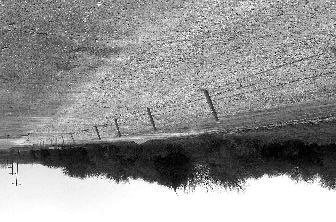
159 Upstream anchor Downstream anchor Figure 58. Installation after test


160 Figure 59. Vehicle after test
161 Occupant Risk Factors In the longitudinal direction, occupant impact velocity was 2.2 m/s at s, maximum s ridedown acceleration was -2.7 g s from to s, and the maximum s average was -1.6 g s between and s. In the lateral direction, the occupant impact velocity was 2.9 m/s at s, the highest s occupant ridedown acceleration was 4.9 g s from to s, and the maximum s average was 2.1 g s between and s. These data and other information pertinent to the test are presented in figure 60. Vehicle angular displacements are presented in appendix D, figure 127, and accelerations versus time traces are shown in appendix E, figures 224 through 234. Assessment of Test Results test: The following NCHRP Report 350 safety evaluation criteria were used to evaluate this crash! Structural Adequacy A. Test article should contain and redirect the vehicle; the vehicle should not penetrate, underride, or override the installation although controlled lateral deflection of the test article is acceptable. Result: The Washington 3-strand cable barrier contained and redirected the 2000P vehicle. Maximum dynamic deflection of the barrier was 3.4 m.! Occupant Risk D. Detached elements, fragments or other debris from the test article should not penetrate or show potential for penetrating the occupant compartment, or present an undue hazard to other traffic, pedestrians, or personnel in a work zone. Deformation of, or intrusions into, the occupant compartment that could cause serious injuries should not be permitted. Result: No detached elements, fragments, or debris were present to penetrate or to show potential for penetrating the occupant compartment, or to present undue hazard to others in the area. No deformation or intrusion of the occupant compartment occurred. F. The vehicle should remain upright during and after collision although moderate roll, pitching and yawing are acceptable. Result: The vehicle remained upright during and after the collision period. 137
 Curb... Test Inertial... Dummy... Gross Static.")

 x-direction... y-direction... PHD (g s)... ASI... Max. 0.050-s Average (g's) x-direction... y-direction... z-direction... 101.4 24.")
... 320 Interior OCDI... FS0000000 Max. Occ. Compart. Deformation (mm)... 0 Post-Impact Behavior (during 1.")
162 0.000 s s s s 138 General Information Test Agency... Test No.... Date... Test Article Type... Name... Installation Length (m)... Material or Key Elements. Soil Type and Condition. Test Vehicle Type... Designation... Model... Mass (kg) Curb... Test Inertial... Dummy... Gross Static... Texas Transportation Institute /16/00 Cable Barrier WSDOT Cable Rail with NY terminal Strand Wire Cable, Top at 770 mm, with New York Cable Terminal Standard Soil, Dry Production 2000P 1994 Chevrolet 2500 Pickup Truck No dummy 2000 Impact Conditions Speed (km/h)... Angle (deg)... Exit Conditions Speed (km/h)... Angle (deg)... Occupant Risk Values Impact Velocity (m/s) x-direction... y-direction... THIV (km/h)... Ridedown Accelerations (g's) x-direction... y-direction... PHD (g s)... ASI... Max s Average (g's) x-direction... y-direction... z-direction Stopped N/A Test Article Deflections (m) Dynamic Permanent Vehicle Damage Exterior VDS... 11LFQ2 CDC... 11FLEK2 & 11LDEW2 Maximum Exterior Vehicle Crush (mm) Interior OCDI... FS Max. Occ. Compart. Deformation (mm)... 0 Post-Impact Behavior (during 1.0 s after impact) Max. Yaw Angle (deg)... Max. Pitch Angle (deg)... Max. Roll Angle (deg)... Figure 60. Summary of results for WSDOT Cable Barrier test, NCHRP Report 350 test
163 ! Vehicle Trajectory K. After collision it is preferable that the vehicle s trajectory not intrude into adjacent traffic lanes. Result: The vehicle did not intrude into adjacent traffic lanes. Final rest of the vehicle was over post 22. L. The occupant impact velocity in the longitudinal direction should not exceed 12 m/s and the occupant ridedown acceleration in the longitudinal direction should not exceed 20 G s. Result: The longitudinal occupant impact velocity was 2.2 m/s and ridedown acceleration was -2.7 g s. M. The exit angle from the test article preferably should be less than 60 percent of the test impact angle, measured at time of vehicle loss of contact with the test device. Result: The vehicle did not exit the test installation. The following supplemental evaluation factors and terminology were used for visual assessment of test results: PASSENGER COMPARTMENT INTRUSION 1. Windshield Intrusion a. No windshield contact b. Windshield contact, no damage c. Windshield contact, no intrusion d. Device embedded in windshield, no significant intrusion e. Complete intrusion into passenger compartment f. Partial intrusion into passenger compartment 2. Body Panel Intrusion yes or no LOSS OF VEHICLE CONTROL 1. Physical loss of control 3. Perceived threat to other vehicles 2. Loss of windshield visibility 4. Debris on pavement The vehicle could have been kept under control, there was no loss of visibility, no perceived threat to other vehicles, and no debris on pavement. 139
164 PHYSICAL THREAT TO WORKERS OR OTHER VEHICLES 1. Harmful debris that could injure workers or others in the area 2. Harmful debris that could injure occupants in other vehicles No debris of significance that would harm others in the area was present. VEHICLE AND DEVICE CONDITION 1. Vehicle Damage a. None b. Minor scrapes, scratches or dents c. Significant cosmetic dents d. Major dents to grill and body panels e. Major structural damage 2. Windshield Damage a. None b. Minor chip or crack c. Broken, no interference with visibility d. Broken and shattered, visibility restricted but remained intact e. Shattered, remained intact but partially dislodged f. Large portion removed g. Completely removed 3. Device Damage a. None b. Superficial c. Substantial, but can be straightened d. Substantial, replacement parts needed for repair e. Cannot be repaired 140
165 THRIE BEAM GUARDRAIL (STEEL POSTS AND ROUTED WOOD BLOCKOUTS) (NCHRP REPORT 350 TEST NO. 3-11) Test Conditions The test performed on the thrie beam guardrail (test ) corresponds to NCHRP Report 350 test designation The CIP for this test was determined, using information contained in NCHRP Report 350, to be 4.5 m upstream of the splice at the one-third point, or 805 mm upstream of post 14 of the thrie beam guardrail system. Test Article The thrie beam guardrail system consisted of 2.1-m-long W150x14 steel posts, spaced 1.9 m apart, with routed wood blockouts, and 3.8-m-long 12-gauge thrie beam rail elements. A cross section of the modified thrie beam guardrail system is shown in figure 1. The routed wood blockouts were 554 mm long, 200 mm deep, and 150 mm wide. A 100-mm-wide, 10-mm-deep channel was routed out and centered on the post side of the blockout to fit over the face of the post. The blockouts and thrie beam rail elements were attached to the flange of the posts with two 16-mm-diameter through bolts. No backup plates or washers were used. The mounting height of the thrie beam rail was 550 mm to the center. The test installation consisted of a 45.7-m-long length-of-need section of thrie beam guardrail with a 1.9-m-long transition section from the thrie beam to the W-beam rail element, and a 11.4-mlong LET at each end, for a total installation length of 68.5 m. The details and layout of the test installation are shown in figure 61. Photographs of the completed installation as tested are shown in figure 62. Soil and Weather Conditions The crash test was performed on the morning of April 9, Ten days before the test 49 mm of rainfall was recorded. No other rainfall was recorded for the remaining 10 recording days prior to the test. Moisture content of the NCHRP Report 350 standard soil in which the guardrail was installed was 6.6 percent, 7.5 percent, and 7.1 percent at posts 13, 15, and 17, respectively. Weather conditions at the time of testing were as follows: wind speed: 6 km/h; wind direction: 45 degrees with respect to the vehicle (vehicle was traveling in a northwesterly direction); temperature: 28EC; relative humidity: 60 percent. Test Vehicle A 1993 Chevrolet Cheyenne 2500 pickup truck, shown in figure 63, was used for the crash test. Test inertia weight of the vehicle was 2000 kg, and its gross static weight was 2076 kg. The height to the lower edge of the vehicle front bumper was 390 mm and to the upper edge of the front bumper was 605 mm. Additional dimensions and information on the vehicle are given in appendix B, figure
166 142 Figure 61. Details of the thrie beam guardrail with 2.1-m steel posts and wood blockouts installation for test


167 Figure 62. Thrie beam guardrail installation prior to test


168 Figure 63. Vehicle before test
169 Impact Description The 2000P vehicle, traveling at a speed of 98.2 km/h, impacted the thrie beam guardrail installation 805 mm upstream of post 14 at an impact angle of 24.4 degrees. Shortly after impact posts 13 and 14 moved. At s, the front of the vehicle contacted post 14, and at s, post 15 moved. By s, post 12 moved, and at s, the vehicle began to redirect. The left front wheel steered left at s, and by s, post 16 moved. At s, the vehicle contacted post 15, and at s, post 17 moved. By s, the vehicle contacted post 16, and by s, the right rear of the vehicle contacted the rail element. Post 18 moved at s, and at s, the front left tire lost contact with the ground. The vehicle, traveling at 75.9 km/h, was parallel with the test installation at s. At s, the vehicle contacted post 17, and at s, the left rear tire lost contact with the ground. By s, the vehicle lost contact with the test installation and was traveling at a speed of 72.5 km/h and an exit angle of 11.3 degrees. The left front and rear tires of the vehicle returned to the ground surface at s and s, respectively. Brakes on the vehicle were applied at 3.2 s. The vehicle came to rest 67.0 m down from impact and 30.5 m toward traffic lanes. Sequential photographs of the collision are shown in appendix C, figures 112 and 113. Damage to Test Article The thrie beam installation sustained minimal damage as shown in figure 64. The upstream end anchor moved 10 mm and posts 2 through 11 were disturbed. Post 12 moved back 13 mm, post 13 moved back 50 mm, and post 14 was pushed back 155 mm. Both post bolts at post 15 pulled through the rail element and the post was rotated. The blockout remained attached to the post 15 and the post was pushed back 235 mm. Post 16 was pushed back 145 mm and post 17 was back 57 mm. Posts 19 through 29 were disturbed. Maximum dynamic deflection during the test was 0.58 m and maximum permanent deformation was 0.42 m. The vehicle was in contact with the rail element for 6.1 m. Vehicle Damage Damage to the 2000P vehicle was also minimal, as shown in figure 65. Structural damage was imparted to the right side rod ends, right upper and lower A-arms, the stabilizer bar and the right front frame. Also damaged were the front bumper, grill, fan, radiator, right front quarter panel, right front tire and rim, and the right door was jammed. Maximum exterior crush to the vehicle was 280 mm at the front right corner at bumper height. Maximum occupant compartment deformation was 75 mm in the center floor pan area. Exterior vehicle crush and occupant compartment measurements are shown in appendix B, tables 45 and


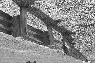
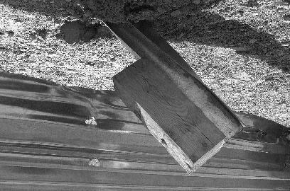
170 146 Figure 64. Installation after test


171 Figure 65. Vehicle after test
172 Occupant Risk Factors In the longitudinal direction, occupant impact velocity was 7.0 m/s at s, maximum s ridedown acceleration was -7.6 g s from to s, and the maximum s average was -5.6 g s between and s. For informational purposes, in the lateral direction, the occupant impact velocity was 6.4 m/s at s, the highest s occupant ridedown acceleration was -9.3 g s from to s, and the maximum s average was -7.2 g s between and s. These data and other information pertinent to the test are presented in figure 66. Vehicle angular displacements are presented in appendix D, figure 128, and accelerations versus time traces are shown in appendix E, figures 235 through 245. Assessment of Test Results test: The following NCHRP Report 350 safety evaluation criteria were used to evaluate this crash! Structural Adequacy A. Test article should contain and redirect the vehicle; the vehicle should not penetrate, underride, or override the installation although controlled lateral deflection of the test article is acceptable. Result: The thrie beam guardrail with 2.1-m-long steel posts and wood blockouts contained and redirected the 2000P vehicle. The vehicle did not penetrate, underride, or override the installation. Maximum lateral deflection of the installation was 0.58 m.! Occupant Risk D. Detached elements, fragments or other debris from the test article should not penetrate or show potential for penetrating the occupant compartment, or present an undue hazard to other traffic, pedestrians, or personnel in a work zone. Deformation of, or intrusions into, the occupant compartment that could cause serious injuries should not be permitted. Result: The rail element separated from post 15. No other detached elements, fragments, or other debris were present. Neither the separated rail element nor the post penetrated or showed potential for penetrating the occupant compartment or presented undue hazard to others in the area. Maximum occupant compartment deformation was 75 mm in the center floor pan area. Due to the location, this deformation was judged to not cause serious injury. 148
 Curb... Test Inertial... Dummy... Gross Static.")
... Angle (deg).")
... ASI... Max. 0.050-s Average (g's) x-direction... y-direction... z-direction... 98.2 24.4 72.5 11.3 7.0 6.4 26.4-7.6-9.3 9.9 0.93-5.6-7.2-3.")
... Post-Impact Behavior (during 1.0 s after impact) Max. Yaw Angle (deg)... Max. Pitch Angle (deg)... Max. Roll Angle (deg)... 0.58 0.")
173 0.000 s s s s 149 General Information Test Agency... Test No.... Date... Test Article Type... Name... Installation Length (m)... Material or Key Elements. Soil Type and Condition. Test Vehicle Type... Designation... Model... Mass (kg) Curb... Test Inertial... Dummy... Gross Static... Texas Transportation Institute /09/99 Guardrail Thrie Beam Guardrail 68.5 Thrie Beam Guardrail with 2.1 m Steel Posts and Routed Wood Blockouts Standard Soil, Dry Production 2000P 1993 Chevrolet 2500 Pickup Truck Impact Conditions Speed (km/h)... Angle (deg)... Exit Conditions Speed (km/h)... Angle (deg)... Occupant Risk Values Impact Velocity (m/s) x-direction... y-direction... THIV (km/h)... Ridedown Accelerations (g's) x-direction... y-direction... PHD (g s)... ASI... Max s Average (g's) x-direction... y-direction... z-direction Test Article Deflections (m) Dynamic... Permanent... Vehicle Damage Exterior VDS... CDC... Maximum Exterior Vehicle Crush (mm)... Interior OCDI... Max. Occ. Compart. Deformation (mm)... Post-Impact Behavior (during 1.0 s after impact) Max. Yaw Angle (deg)... Max. Pitch Angle (deg)... Max. Roll Angle (deg) RFQ3 01RFEK2 &01RYEW2 280 RF Figure 66. Summary of results for the Thrie Beam Guardrail (steel posts/wood blockouts) test, NCHRP Report 350 test 3-11.
174 F. The vehicle should remain upright during and after collision although moderate roll, pitching and yawing are acceptable. Result: The 2000P vehicle remained upright and relatively stable during and after the collision event.! Vehicle Trajectory K. After collision it is preferable that the vehicle s trajectory not intrude into adjacent traffic lanes. Result: The vehicle did intrude into adjacent traffic lanes as it came to rest 67.0 m down from impact and 30.5 m toward traffic lanes. L. The occupant impact velocity in the longitudinal direction should not exceed 12 m/s and the occupant ridedown acceleration in the longitudinal direction should not exceed 20 g s. Result: Longitudinal occupant impact velocity was 7.0 m/s and longitudinal ridedown acceleration was -7.6 g s. M. The exit angle from the test article preferably should be less than 60 percent of the test impact angle, measured at time of vehicle loss of contact with the test device. Result: The exit angle at loss of contact with the installation was 11.3 degrees, which was 46 percent of the impact angle. The following supplemental evaluation factors and terminology were used for visual assessment of test results: PASSENGER COMPARTMENT INTRUSION 1. Windshield Intrusion a. No windshield contact b. Windshield contact, no damage c. Windshield contact, no intrusion d. Device embedded in windshield, no significant intrusion e. Complete intrusion into passenger compartment f. Partial intrusion into passenger compartment 2. Body Panel Intrusion yes or no 150
175 LOSS OF VEHICLE CONTROL 1. Physical loss of control 3. Perceived threat to other vehicles 2. Loss of windshield visibility 4. Debris on pavement The vehicle could have been kept under control, there was no loss of visibility, no perceived threat to other vehicles, and no debris on pavement. PHYSICAL THREAT TO WORKERS OR OTHER VEHICLES 1. Harmful debris that could injure workers or others in the area 2. Harmful debris that could injure occupants in other vehicles No debris of significance that would harm others in the area was present. VEHICLE AND DEVICE CONDITION 1. Vehicle Damage a. None b. Minor scrapes, scratches or dents c. Significant cosmetic dents d. Major dents to grill and body panels e. Major structural damage 2. Windshield Damage a. None b. Minor chip or crack c. Broken, no interference with visibility d. Broken and shattered, visibility restricted but remained intact e. Shattered, remained intact but partially dislodged f. Large portion removed g. Completely removed 3. Device Damage a. None b. Superficial c. Substantial, but can be straightened d. Substantial, replacement parts needed for repair e. Cannot be repaired 151
176 THRIE BEAM ON STRONG WOOD POSTS (NCHRP REPORT 350 TEST NO. 3-11) Test Conditions The test performed on the thrie beam on strong wood posts ( ) corresponds to NCHRP Report 350 test designation The CIP for this test was determined using information contained in NCHRP Report 350 and accordingly was determined to be the midpoint of the span between posts 15 and 16 of the strong wood post thrie beam guardrail. Test Article The strong wood post thrie beam guardrail system consisted of 2050-mm-long, 150-mm by 200-mm wood posts spaced 1.9 m apart with 150-mm by 200-mm by 554-mm blockouts. A cross section of the strong wood post thrie beam guardrail system is shown in figure 1. The blockout and rail element were attached to each post with two 16-mm-diameter button head bolts without a washer under the head. One flat washer was used under the nut. The mounting height of the thrie beam rail was 550 mm to the center and 804 mm to the top of the thrie beam rail element. The test installation consisted of a 45.7-m-long length-of-need section of strong wood post thrie beam guardrail with a 1.9-m-long transition section from the thrie beam to the W-beam rail element, and a 15.2-m-long ET-2000 at each end, for a total installation length of 80.0 m. The details and layout of the test installation are shown in figure 67. Photographs of the completed installation as tested are shown in figure 68. Soil and Weather Conditions The test was performed on the morning of July 3, A total of 10 mm of rain occurred four days before the test. No other rain occurred during the remaining 10 recording days prior to the test. Moisture content of the NCHRP Report 350 standard soil in which the guardrail was installed was 7.7 percent, 9.7 percent, and 9.6 percent at posts 16, 18, and 20, respectively. Weather conditions during the time of the test were as follows: wind speed: 0 km/h; wind direction: N/A (vehicle was traveling in a southwesterly direction); temperature: 33EC; relative humidity: 82 percent. Test Vehicle A 1993 Chevrolet 2500 pickup truck, shown in figure 69, was used for the crash test. Test inertia weight of the vehicle was 2000 kg, and its gross static weight was 2075 kg. The height to the lower edge of the vehicle bumper was 370 mm and it was 600 mm to the upper edge of the bumper. Additional dimensions and information on the vehicle are given in appendix B, figure
177 153 Figure 67. Details of the Strong wood post thrie beam guardrail installation for test


178 Figure 68. Strong wood post thrie beam guardrail installation prior to test


179 Figure 69. Vehicle before test
180 Impact Description The vehicle, traveling at 99.6 km/h, impacted the strong wood post thrie beam guardrail 609 mm before post 16 at an impact angle of 23.6 degrees. Shortly after impact, posts 16 and 15 moved, followed by movement in the thrie beam element, and then movement at post 17 at s. The vehicle contacted post 16 at s and the vehicle redirected at s. Post 18 moved at s, and post 19 moved shortly after. The front of the vehicle contacted post 17 at s and the right front tire impacted post 17 at s, which caused the post to fracture just below ground level. At s, post 20 moved and at s, the vehicle contacted post 18. The right front tire impacted post 18 at s, which caused the post to split along the longitudinal axis. The rear of the vehicle contacted the thrie beam rail element at s. At s, the vehicle was traveling parallel with the guardrail at a speed of 75.8 km/h. The front of the vehicle contacted post 19 at s and the front of the vehicle lost contact with the rail element at s. The vehicle lost contact with the rail at s and was traveling at an exit speed of 73.6 km/h and an exit angle of 14.7 degrees. The vehicle immediately steered back into the rail and contacted the guardrail again at post 41 at s. The vehicle rode off the end of the terminal and rotated counterclockwise. Brakes on the vehicle were not applied. The vehicle subsequently came to rest 68.6 m down and 1.8 m behind the installation. Sequential photographs of the test period are shown in appendix C, figures 114 and 115. Damage to Test Article Damage to the strong wood post thrie beam guardrail is shown in figure 70. Post 17 fractured just below ground level and post 18 split along the longitudinal axis. The bolts pulled out of the rail element at posts 17 and 18. The ET-2000 end terminal on the downstream end was disturbed as were posts 6 through 14. Posts 15 through 20 were pushed back with a maximum displacement of 110 mm at post 16. Maximum dynamic deflection of the guardrail was 676 mm and the maximum permanent deformation was 390 mm between posts 16 and 17. Total length of contact during the initial impact was 6.3 m. The vehicle contacted the installation again at post 40 and rode off the end (post 43). Vehicle Damage The bumper, hood, grill, fan, radiator, right front tire and wheel, right door, right front and rear quarter panels, and left door were damaged and the windshield was shattered as shown in figure 71. Structural damage included the right upper and lower A-arms, right spindle and rod ends, stabilizer bar, right front frame, firewall, and floor pan. Maximum exterior crush to the vehicle was 470 mm at the right front corner of the bumper. Maximum occupant compartment deformation was 30 mm in the center floor pan area under the instrument panel. Exterior crush measurements and occupant compartment measurements are shown in appendix B, tables 47 and

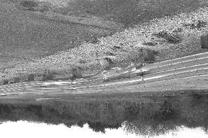
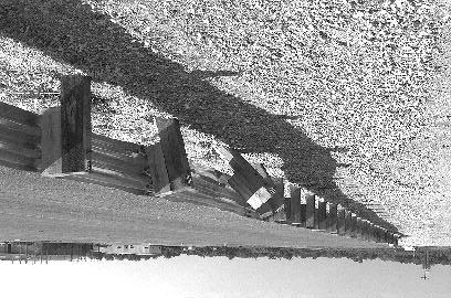
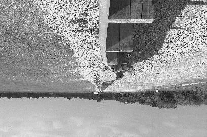
181 157 Figure 70. Installation after test


182 Figure 71. Vehicle after test
183 Occupant Risk Factors In the longitudinal direction, the occupant impact velocity was 6.3 m/s at s, the highest s occupant ridedown acceleration was -8.4 g s from to s, and the maximum s average acceleration was -5.5 g s between and s. In the lateral direction, the occupant impact velocity was 5.6 m/s at s, the highest s occupant ridedown acceleration was -9.0 g s from to s, and the maximum s average was -5.8 g s between and s. These data and other pertinent information from the test are summarized in figure 72. Vehicle angular displacements are displayed in appendix D, figure 129. Vehicular accelerations versus time traces are presented in appendix E, figures 246 through 256. Assessment of Test Results test: The following NCHRP Report 350 safety evaluation criteria were used to evaluate this crash! Structural Adequacy A. Test article should contain and redirect the vehicle; the vehicle should not penetrate, underride, or override the installation although controlled lateral deflection of the test article is acceptable. Result: The strong wood post thrie beam guardrail contained and redirected the vehicle. The vehicle did not penetrate, underride, or override the installation. Maximum dynamic deflection of the installation was 676 mm.! Occupant Risk D. Detached elements, fragments or other debris from the test article should not penetrate or show potential for penetrating the occupant compartment, or present an undue hazard to other traffic, pedestrians, or personnel in a work zone. Deformation of, or intrusions into, the occupant compartment that could cause serious injuries should not be permitted. Result: No detached elements, fragments, or other debris were present to penetrate or to show potential for penetrating the occupant compartment, or to present undue hazard to others in the area. Maximum occupant compartment deformation was 30 mm in the center front floor pan area under the instrument panel and should not cause serious injury. F. The vehicle should remain upright during and after collision although moderate roll, pitching and yawing are acceptable. Result: The vehicle remained upright during and after the collision. 159
 Curb... Test Inertial... Dummy... Gross Static.")
.")
 x-direction... y-direction... PHD (g s)... ASI... Max. 0.050-s Average (g's) x-direction... y-direction... z-direction... 99.6 23.6 73.6 14.7 6.")
... Post-Impact Behavior (during 1.0 s after impact) Max. Yaw Angle (deg)... Max. Pitch Angle (deg)... Max. Roll Angle (deg).")
184 0.000 s s s s 160 General Information Test Agency... Test No.... Date... Test Article Type... Name... Installation Length (m)... Material or Key Elements. Soil Type and Condition. Test Vehicle Type... Designation... Model... Mass (kg) Curb... Test Inertial... Dummy... Gross Static... Texas Transportation Institute /03/98 Guardrail Strong Wood Post Thrie Beam Guardrail ga Thrie Beam on Strong Wood Posts With Wood Blockouts Standard Soil, Dry Production 2000P 1993 Chevrolet 2500 Pickup Truck Impact Conditions Speed (km/h)... Angle (deg)... Exit Conditions Speed (km/h)... Angle (deg)... Occupant Risk Values Impact Velocity (m/s) x-direction... y-direction... THIV (km/h)... Ridedown Accelerations (g's) x-direction... y-direction... PHD (g s)... ASI... Max s Average (g's) x-direction... y-direction... z-direction Test Article Deflections (m) Dynamic Permanent Vehicle Damage Exterior VDS... CDC... Maximum Exterior Vehicle Crush (mm)... Interior OCDI... Max. Occ. Compart. Deformation (mm)... Post-Impact Behavior (during 1.0 s after impact) Max. Yaw Angle (deg)... Max. Pitch Angle (deg)... Max. Roll Angle (deg)... 01RFQ4 01FREK3 & 01RYEW3 470 FS Figure 72. Summary of results for the thrie beam guardrail on strong wood posts, NCHRP Report 350 test 3-11.
185 ! Vehicle Trajectory K. After collision it is preferable that the vehicle s trajectory not intrude into adjacent traffic lanes. Result: The vehicle did not intrude into adjacent traffic lanes. L. The occupant impact velocity in the longitudinal direction should not exceed 12 m/s and the occupant ridedown acceleration in the longitudinal direction should not exceed 20 g s. Result: Longitudinal occupant impact velocity was 6.3 m/s and longitudinal ridedown acceleration was -8.4 g s. M. The exit angle from the test article preferably should be less than 60 percent of the test impact angle, measured at time of vehicle loss of contact with the test device. Result: The exit angle at loss of contact was 14.7 degrees, which was 62 percent of the impact angle; however, the vehicle steered back toward the installation. The following supplemental evaluation factors and terminology were used for visual assessment of test results: PASSENGER COMPARTMENT INTRUSION 1. Windshield Intrusion a. No windshield contact b. Windshield contact, no damage c. Windshield contact, no intrusion d. Device embedded in windshield, no significant intrusion e. Complete intrusion into passenger compartment f. Partial intrusion into passenger compartment 2. Body Panel Intrusion yes or no LOSS OF VEHICLE CONTROL 1. Physical loss of control 3. Perceived threat to other vehicles 2. Loss of windshield visibility 4. Debris on pavement The vehicle could have been kept under control, there was no loss of visibility, no perceived threat to other vehicles, and no debris on pavement. 161
186 PHYSICAL THREAT TO WORKERS OR OTHER VEHICLES 1. Harmful debris that could injure workers or others in the area 2. Harmful debris that could injure occupants in other vehicles No debris of significance that would harm others in the area was present. VEHICLE AND DEVICE CONDITION 1. Vehicle Damage a. None b. Minor scrapes, scratches or dents c. Significant cosmetic dents d. Major dents to grill and body panels e. Major structural damage 2. Windshield Damage a. None b. Minor chip or crack c. Broken, no interference with visibility d. Broken and shattered, visibility restricted but remained intact e. Shattered, remained intact but partially dislodged f. Large portion removed g. Completely removed 3. Device Damage a. None b. Superficial c. Substantial, but can be straightened d. Substantial, replacement parts needed for repair e. Cannot be repaired 162
187 MODIFIED THRIE BEAM GUARDRAIL (NCHRP REPORT 350 TEST NO. 4-12) Test Conditions The test performed on the modified thrie beam guardrail (test ) corresponds to NCHRP Report 350 test designation The CIP for this test was determined using information contained in NCHRP Report 350 and accordingly was determined to be the midpoint of the span between posts 17 and 18 of the modified thrie beam guardrail. Test Article The modified thrie beam guardrail system consisted of 2.1-m-long W150x14 steel posts spaced 1.9 m apart with W360x33 blockouts. A cross section of the modified thrie beam guardrail system is shown in figure 73. The blockouts were 432 mm long, 457 mm deep, and 152 mm wide at the flanges. The web of the blockout had a cutout measuring 152 mm at the bottom and angled upward at 40 degrees to the flange upon which the thrie beam was attached. The blockout was attached to the post with four 16-mm-diameter bolts and the thrie beam rail element was attached to the blockout with a single 16-mm-diameter button head bolt without a washer. The mounting height of the thrie beam rail was 610 mm to the center and 864 mm to the top of the thrie beam rail element. The test installation consisted of a 45.7-m-long length-of-need section of modified thrie beam guardrail with a 1.9-m-long transition section from the thrie beam to the W-beam rail element, and a 15.2-m-long ET-2000 at each end, for a total installation length of 80.0 m. The details and layout of the test installation are shown in figure 73. Photographs of the completed installation are shown in figure 74. Soil and Weather Conditions The test was performed the morning of June 12, No rain had occurred for the 10 days prior to the test. Moisture content at posts 18, 20, and 22 was 6.7 percent, 4.0 percent, and 5.1 percent, respectively. Weather conditions during the time of the test were as follows: wind speed: 16 km/h; wind direction: 345 degrees with respect to the vehicle (vehicle was traveling in a southwesterly direction); temperature: 34EC; relative humidity: 51 percent. Test Vehicle A 1988 GMC 7000 single-unit truck, shown in figure 75, was used for the crash test. Test inertia weight of the vehicle was 8000 kg, and its gross static weight was 8000 kg. The height to the lower edge of the vehicle bumper was 520 mm and it was 815 mm to the upper edge of the bumper. Additional dimensions and information on the vehicle are given in appendix B, figure
188 164 Figure 73. Details of the modified thrie beam guardrail installation for test


189 Figure 74. Modified thrie beam guardrail installation prior to test


190 Figure 75. Vehicle before test
191 Impact Description The vehicle, traveling at 78.8 km/h, impacted the modified thrie beam guardrail 750 mm before post 18 at an impact angle of 15.7 degrees. Shortly after impact, post 18 and then post 17 moved. By s after impact, the vehicle contacted post 18 and at s, post 19 moved. The vehicle began to redirect at s and post 20 moved at s. At s, the vehicle contacted post 19 and at s, post 21 moved. Post 22 moved at s and the vehicle contacted post 21 at s. Post 23 moved at s, the right rear tire contacted the guardrail at s, and the front of the vehicle contacted post 22 at s. The vehicle was traveling parallel with the guardrail at s at a speed of 64.6 km/h. At s, the front wheels turned to the right and the front of the vehicle lost contact with the rail at s. The rear of the vehicle lost contact with the guardrail near post 26 at s and was traveling at 64.0 km/h and an exit angle of 8.2 degrees. The vehicle rotated clockwise at s and contacted the guardrail between posts 27 and 28 at s. At s, the front wheels turned to the left and at s, the vehicle lost contact with the guardrail just past post 30. The vehicle continued forward and then contacted the ET-2000 between posts 37 and 38 at s. As the vehicle continued forward, the vehicle pulled the ET-2000 head off the end. The vehicle rode off the end of the terminal and brakes on the vehicle were applied at 4.9 s. The vehicle subsequently came to rest 70.7 m down from impact and in line with the installation. Sequential photographs of the test period are shown in appendix C, figures 116 and 117. Damage to Test Article Damage to the modified thrie beam guardrail is shown in figure 76. Posts 19 through 26 were deformed and the blockouts on those posts were significantly deformed. The blockouts on posts 17, 18, and 27 were slightly deformed. The guardrail bolts pulled through the thrie beam at posts 20, 23, 24, and 25. Tire marks were on the face of posts 20 and 21. Length of contact during the initial collision was 16.0 m. For 2.8 m of that distance, the truck rode on top of the thrie beam. The second contact occurred between posts 27 and 28 and continued to just past post 30. The third contact occurred between posts 37 and 38 and the vehicle rode off the end, taking the ET-2000 head off the end. Maximum dynamic deflection during the test was 0.71 m and maximum permanent deformation was 0.51 m, both occurring near post 21. Vehicle Damage Minimal damage was sustained by the vehicle as shown in figure 77. Structural damage was received by the front axle and right front wheel. The lower right front corner of the cargo box received a dent as well as the right side fuel tank. The bumper and supports, hood, right front quarter panel, grill, and right door step were damaged. The right door was jammed and the right outside tire received gouges. Maximum exterior vehicle crush was 140 mm at the right front corner of the bumper. 167
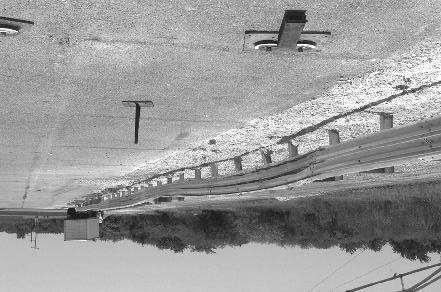
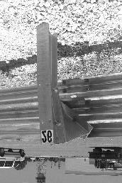
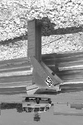
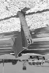
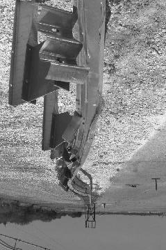
192 Figure 76. Installation after test


193 Figure 77. Vehicle after test
194 Occupant Risk Factors In the longitudinal direction, the occupant impact velocity was 3.5 m/s at s, the highest s occupant ridedown acceleration was -2.9 g s from to s, and the maximum s average acceleration was -1.4 g s between and s. In the lateral direction, the occupant impact velocity was 2.4 m/s at s, the highest s occupant ridedown acceleration was 3.8 g s from to s, and the maximum s average was 2.3 g s between and s. These data and other pertinent information from the test are summarized in figure 78. Vehicle angular displacements are displayed in appendix D, figure 130. Vehicular accelerations versus time traces are presented in appendix E, figures 257 through 263. Assessment of Test Results test: The following NCHRP Report 350 safety evaluation criteria were used to evaluate this crash! Structural Adequacy A. Test article should contain and redirect the vehicle; the vehicle should not penetrate, underride, or override the installation although controlled lateral deflection of the test article is acceptable. Result: The modified thrie beam guardrail was contained and smoothly redirected. The vehicle did not penetrate, underride, or override the installation. Maximum dynamic deflection during the test was 0.71 m.! Occupant Risk D. Detached elements, fragments or other debris from the test article should not penetrate or show potential for penetrating the occupant compartment, or present an undue hazard to other traffic, pedestrians, or personnel in a work zone. Deformation of, or intrusions into, the occupant compartment that could cause serious injuries should not be permitted. Result: No detached elements, fragments, or other debris were present to penetrate or to show potential for penetrating the occupant compartment, or to present undue hazard to others in the area. No deformation or intrusion into the occupant compartment occurred. G. It is preferable, although not essential, that the vehicle remain upright during and after the collision. Result: The vehicle remained upright and stable during and after the collision. 170
 Curb... Test Inertial... Dummy... Gross Static.")

 x-direction... y-direction... PHD (g s)... ASI... Max. 0.050-s Average (g's) x-direction... y-direction... z-direction... 78.8 15.7 64.0 8.")
... 140 Interior OCDI... RS0000000 Max. Occ. Compart. Deformation (mm)... 0 Post-Impact Behavior (during 1.0 s after impact) Max.")
195 0.000 s s s s 171 General Information Test Agency... Test No.... Date... Test Article Type... Name... Installation Length (m)... Material or Key Elements. Soil Type and Condition. Test Vehicle Type... Designation... Model... Mass (kg) Curb... Test Inertial... Dummy... Gross Static... Texas Transportation Institute /12/98 Guardrail Modified Thrie Beam Guardrail gauge thrie beam on W150x14 steel posts and steel blockouts Standard Soil, Dry Production 8000S 1988 GMC 7000 Single-Unit Truck No dummy 8000 Impact Conditions Speed (km/h)... Angle (deg)... Exit Conditions Speed (km/h)... Angle (deg)... Occupant Risk Values Impact Velocity (m/s) x-direction... y-direction... THIV (km/h)... Ridedown Accelerations (g's) x-direction... y-direction... PHD (g s)... ASI... Max s Average (g's) x-direction... y-direction... z-direction Test Article Deflections (m) Dynamic Permanent Vehicle Damage Exterior VDS... N/A CDC... N/A Maximum Exterior Vehicle Crush (mm) Interior OCDI... RS Max. Occ. Compart. Deformation (mm)... 0 Post-Impact Behavior (during 1.0 s after impact) Max. Yaw Angle (deg) Max. Pitch Angle (deg) Max. Roll Angle (deg) Figure 78. Summary of results for test , NCHRP Report 350 test 4-12.
NCHRP Report 350 Test 4-12 of the Modified Thrie Beam Guardrail
 NCHRP Report 350 Test 4-12 of the Modified Thrie Beam Guardrail PUBLICATION NO. FHWA-RD-99-065 DECEMBER 1999 Research, Development, and Technology Turner-Fairbank Highway Research Center 6300 Georgetown
GUARDRAIL TESTING MODIFIED ECCENTRIC LOADER TERMINAL (MELT) AT NCHRP 350 TL-2. Dean C. Alberson, Wanda L. Menges, and Rebecca R.
 AT NCHRP 350 TL-2. Dean C. Alberson, Wanda L. Menges, and Rebecca R.") GUARDRAIL TESTING MODIFIED ECCENTRIC LOADER TERMINAL (MELT) AT NCHRP 350 TL-2 Dean C. Alberson, Wanda L. Menges, and Rebecca R. Haug Prepared for The New England Transportation Consortium July 2002 NETCR
GUARDRAIL TESTING MODIFIED ECCENTRIC LOADER TERMINAL (MELT) AT NCHRP 350 TL-2 Dean C. Alberson, Wanda L. Menges, and Rebecca R. Haug Prepared for The New England Transportation Consortium July 2002 NETCR
Manual for Assessing Safety Hardware
 American Association of State Highway and Transportation Officials Manual for Assessing Safety Hardware 2009 vii PREFACE Effective traffic barrier systems, end treatments, crash cushions, breakaway devices,
TEXAS TRANSPORTATION INSTITUTE THE TEXAS A & M UNIVERSITY SYSTEM COLLEGE STATION, TEXAS 77843
 NCHRP REPORT 350 TEST 3-11 OF THE STEEL-BACKED TIMBER GUARDRAIL by D. Lance Bullard, Jr., P.E. Associate Research Engineer Wanda L. Menges Associate Research Specialist and Sandra K. Schoeneman Research
TEXAS TRANSPORTATION INSTITUTE THE TEXAS A & M UNIVERSITY SYSTEM COLLEGE STATION, TEXAS
 NCHRP REPORT 350 TEST 4-21 OF THE ALASKA MULTI-STATE BRIDGE RAIL THRIE-BEAM TRANSITION by C. Eugene Buth Senior Research Engineer William F. Williams Assistant Research Engineer Wanda L. Menges Associate
TEXAS TRANSPORTATION INSTITUTE THE TEXAS A & M UNIVERSITY SYSTEM COLLEGE STATION, TEXAS 77843
 NCHRP REPORT 350 TEST 3-11 OF THE NEW YORK DOT PORTABLE CONCRETE BARRIER WITH I-BEAM CONNECTION (RETEST) by Roger P. Bligh, P.E. Assistant Research Engineer Wanda L. Menges Associate Research Specialist
Form DOT F (8-72) Texas Transportation Institute The Texas A&M University System College Station, Texas
 Texas Transportation Institute The Texas A&M University System College Station, Texas") 1. Report No. FHWA/TX-02/4162-1 Technical Report Documentation Page 2. Government Accession No. 3. Recipient's Catalog No. 4. Title and Subtitle EVALUATION OF TEXAS GRID-SLOT PORTABLE CONCRETE BARRIER
1. Report No. FHWA/TX-02/4162-1 Technical Report Documentation Page 2. Government Accession No. 3. Recipient's Catalog No. 4. Title and Subtitle EVALUATION OF TEXAS GRID-SLOT PORTABLE CONCRETE BARRIER
Evaluation of the Sequential Dynamic Curve Warning System Summary of Full Report Publication No. FHWA-15-CAI-012-A November 2015
 Evaluation of the Sequential Dynamic Curve Warning System Summary of Full Report Publication No. FHWA-15-CAI-012-A November 2015 Source: ISU/TTI Notice This document is disseminated under the sponsorship
NCHRP REPORT 350 TEST 4-12 OF THE MASSACHUSETTS S3-TL4 STEEL BRIDGE RAILING MOUNTED ON CURB AND SIDEWALK
 TEXAS TRANSPORTATION INSTITUTE NCHRP REPORT 350 TEST 4-12 OF THE MASSACHUSETTS S3-TL4 STEEL BRIDGE RAILING MOUNTED ON CURB AND SIDEWALK by C. Eugene Buth Research Engineer and Wanda L. Menges Associate
Evaluation of Barriers for Very High Speed Roadways
 TTI: 0-6071 Evaluation of Barriers for Very High Speed Roadways ISO 17025 Laboratory Testing Certificate # 2821.01 Crash testing performed at: TTI Proving Ground 3100 SH 47, Building 7091 Bryan, TX 77807
AASHTO Manual for Assessing Safety Hardware, AASHTO/FHWA Joint Implementation Plan Standing Committee on Highways September 24, 2015
 AASHTO Manual for Assessing Safety Hardware, 2015 AASHTO/FHWA Joint Implementation Plan Standing Committee on Highways September 24, 2015 Full Scale MASH Crash Tests (NCHRP 22-14(02)) Conducted several
NCHRP Report 350 Crash Testing and Evaluation of the S-Square Mailbox System
 TTI: 0-5210 NCHRP Report 350 Crash Testing and Evaluation of the S-Square Mailbox System ISO 17025 Laboratory Testing Certificate # 2821.01 Crash testing performed at: TTI Proving Ground 3100 SH 47, Building
Texas Transportation Institute The Texas A&M University System College Station, Texas
 1. Report No. FHWA/TX-07/0-5527-1 4. Title and Subtitle DEVELOPMENT OF A LOW-PROFILE TO F-SHAPE TRANSITION BARRIER SEGMENT 2. Government Accession No. 3. Recipient's Catalog No. Technical Report Documentation
Advances in Simulating Corrugated Beam Barriers under Vehicular Impact
 13 th International LS-DYNA Users Conference Session: Automotive Advances in Simulating Corrugated Beam Barriers under Vehicular Impact Akram Abu-Odeh Texas A&M Transportation Institute Abstract W-beam
Transportation Institute
 .JIIIIIII"" Texas Transportation Institute SUMMARY OF TESTING ON 'l'he RENCO TRUCK MOUNTED ATTENUATOR by Wanda L. Menges Associate Research Specialist C. Eugene Buth, P.E. Senior Research Engineer and
MASH 2016 Implementation: What, When and Why
 MASH 2016 Implementation: What, When and Why Roger P. Bligh, Ph.D., P.E. Senior Research Engineer Texas A&M Transportation Institute June 7, 2016 2016 Traffic Safety Conference College Station, Texas Outline
A MASH Compliant W-Beam Median Guardrail System
 0 0 0 0 0 A MASH Compliant W-Beam Median Guardrail System By A. Y. Abu-Odeh, R. P. Bligh, W. Odell, A. Meza, and W. L. Menges Submitted: July 0, 0 Word Count:, + ( figures + tables=,000) =, words Authors:
Texas Transportation Institute The Texas A&M University System College Station, Texas
 2. Government Accession No. 3. Recipient's Catalog No. 1. Report No. FHWA/TX-03/0-4138-3 4. Title and Subtitle PERFORMANCE OF THE TXDOT T202 (MOD) BRIDGE RAIL REINFORCED WITH FIBER REINFORCED POLYMER BARS
PR V2. Submitted by. Professor MIDWEST Vine Street (402) Submitted to
 Submitted to") FINAL REPORT PR4893118-V2 ZONE OF INTRUSION STUDY Submitted by John D. Reid, Ph.D. Professor Dean L.. Sicking, Ph.D., P.E. Professorr and MwRSF Director MIDWEST ROADSIDE SAFETY FACILITY University of Nebraska-Lincoln
FINAL REPORT PR4893118-V2 ZONE OF INTRUSION STUDY Submitted by John D. Reid, Ph.D. Professor Dean L.. Sicking, Ph.D., P.E. Professorr and MwRSF Director MIDWEST ROADSIDE SAFETY FACILITY University of Nebraska-Lincoln
MASH Test 3-11 on the T131RC Bridge Rail
 TTI: 9-1002-12 MASH Test 3-11 on the T131RC Bridge Rail ISO 17025 Laboratory Testing Certificate # 2821.01 Crash testing performed at: TTI Proving Ground 3100 SH 47, Building 7091 Bryan, TX 77807 Test
CRASH TEST AND EVALUATION OF 3-FT MOUNTING HEIGHT SIGN SUPPORT SYSTEM
 TTI: 9-1002-15 CRASH TEST AND EVALUATION OF 3-FT MOUNTING HEIGHT SIGN SUPPORT SYSTEM ISO 17025 Laboratory Testing Certificate # 2821.01 Crash testing performed at: TTI Proving Ground 3100 SH 47, Building
MASH08 TEST 3-11 OF THE ROCKINGHAM PRECAST CONCRETE BARRIER
 Proving Ground Report No. 400001-RPC4 Report Date: July 2009 MASH08 TEST 3-11 OF THE ROCKINGHAM PRECAST CONCRETE BARRIER by C. Eugene Buth, P.E. Research Engineer William F. Williams, P.E. Assistant Research
DEVELOPMENT OF A MASH TL-3 MEDIAN BARRIER GATE
 TTI: 9-1002 DEVELOPMENT OF A MASH TL-3 MEDIAN BARRIER GATE ISO 17025 Laboratory Testing Certificate # 2821.01 Crash testing performed at: TTI Proving Ground 3100 SH 47, Building 7091 Bryan, TX 77807 Research/Test
SUMMARY CHANGES FOR NCHRP REPORT 350 GUIDELINES [NCHRP (02)] Keith A. Cota, Chairman Technical Committee on Roadside Safety June 14, 2007
![SUMMARY CHANGES FOR NCHRP REPORT 350 GUIDELINES [NCHRP (02)] Keith A. Cota, Chairman Technical Committee on Roadside Safety June 14, 2007](/thumbs/87/97351925.jpg "SUMMARY CHANGES FOR NCHRP REPORT 350 GUIDELINES [NCHRP (02)] Keith A. Cota, Chairman Technical Committee on Roadside Safety June 14, 2007") SUMMARY CHANGES FOR NCHRP REPORT 350 GUIDELINES [NCHRP 22-14 (02)] Keith A. Cota, Chairman Technical Committee on Roadside Safety June 14, 2007 BACKGROUND Circular 482 (1962) First full scale crash test
SUMMARY CHANGES FOR NCHRP REPORT 350 GUIDELINES [NCHRP 22-14 (02)] Keith A. Cota, Chairman Technical Committee on Roadside Safety June 14, 2007 BACKGROUND Circular 482 (1962) First full scale crash test
Texas Transportation Institute The Texas A&M University System College Station, Texas
 1. Report No. FHWA/TX-05/9-8132-P7 4. Title and Subtitle TL-4 CRASH TESTING OF THE F411 BRIDGE RAIL 2. Government Accession No. 3. Recipient's Catalog No. 5. Report Date October 2004 Technical Report Documentation
Texas Transportation Institute The Texas A&M University System College Station, Texas
 1. Report No. FHWA/TX-04/9-8132-1 4. Title and Subtitle TESTING AND EVALUATION OF THE FLORIDA JERSEY SAFETY SHAPED BRIDGE RAIL 2. Government Accession No. 3. Recipient's Catalog No. 5. Report Date February
MASH TEST 3-10 ON 31-INCH W-BEAM GUARDRAIL WITH STANDARD OFFSET BLOCKS
 TTI: 9-1002 MASH TEST 3-10 ON 31-INCH W-BEAM GUARDRAIL WITH STANDARD OFFSET BLOCKS ISO 17025 Laboratory Testing Certificate # 2821.01 Crash testing performed at: TTI Proving Ground 3100 SH 47, Building
MASH TEST 3-37 OF THE TxDOT 31-INCH W-BEAM DOWNSTREAM ANCHOR TERMINAL
 TTI: 9-1002 MASH TEST 3-37 OF THE TxDOT 31-INCH W-BEAM DOWNSTREAM ANCHOR TERMINAL ISO 17025 Laboratory Testing Certificate # 2821.01 Crash testing performed at: TTI Proving Ground 3100 SH 47, Building
1962: HRCS Circular 482 one-page document, specified vehicle mass, impact speed, and approach angle for crash tests.
 1 2 3 1962: HRCS Circular 482 one-page document, specified vehicle mass, impact speed, and approach angle for crash tests. 1973: NCHRP Report 153 16-page document, based on technical input from 70+ individuals
Crash Testing Growth Common Roadside Hardware Systems Draft FHWA and AASHTO Requirements for Implementing MASH 2015
 64 th Annual Illinois Traffic Safety and Engineering Conference October 14, 2015 Crash Testing Growth Common Roadside Hardware Systems Draft FHWA and AASHTO Requirements for Implementing MASH 2015 1 https://www.youtube.com/watch?feature
ASTM F TEST M30 ON THE RSS-3000 DROP BEAM SYSTEM
 Proving Ground Test Report No.: 510602-RSS3 Test Report Date: January 2014 ASTM F2656-07 TEST M30 ON THE RSS-3000 DROP BEAM SYSTEM by Dean C. Alberson, Ph.D., P.E. Research Engineer Michael S. Brackin,
Technical Report Documentation Page 2. Government Accession No. 3. Recipient's Catalog No. 1. Report No. FHWA/TX-09/
 1. Report No. FHWA/TX-09/0-6071-1 4. Title and Subtitle ANALYSIS OF ROADSIDE SAFETY DEVICES FOR USE ON VERY HIGH-SPEED ROADWAYS Technical Report Documentation Page 2. Government Accession No. 3. Recipient's
MASH TEST 3-11 OF THE TxDOT T222 BRIDGE RAIL
 TTI: 9-1002-12 MASH TEST 3-11 OF THE TxDOT T222 BRIDGE RAIL ISO 17025 Laboratory Testing Certificate # 2821.01 Crash testing performed at: TTI Proving Ground 3100 SH 47, Building 7091 Bryan, TX 77807 Test
Implementation of AASHTO s Manual for Assessing Safety Hardware (MASH) 2016
 2016") Implementation of AASHTO s Manual for Assessing Safety Hardware (MASH) 2016 Update from the Technical Committee on Roadside Safety Keith Cota, New Hampshire DOT MASH 2016 Overview Background Ballot Results/Dates
Implementation of AASHTO s Manual for Assessing Safety Hardware (MASH) 2016 Update from the Technical Committee on Roadside Safety Keith Cota, New Hampshire DOT MASH 2016 Overview Background Ballot Results/Dates
MASH TEST 3-11 OF THE TxDOT SINGLE SLOPE BRIDGE RAIL (TYPE SSTR) ON PAN-FORMED BRIDGE DECK
 ON PAN-FORMED BRIDGE DECK") TTI: 9-1002 MASH TEST 3-11 OF THE TxDOT SINGLE SLOPE BRIDGE RAIL (TYPE SSTR) ON PAN-FORMED BRIDGE DECK ISO 17025 Laboratory Testing Certificate # 2821.01 Crash testing performed at: TTI Proving Ground
TTI: 9-1002 MASH TEST 3-11 OF THE TxDOT SINGLE SLOPE BRIDGE RAIL (TYPE SSTR) ON PAN-FORMED BRIDGE DECK ISO 17025 Laboratory Testing Certificate # 2821.01 Crash testing performed at: TTI Proving Ground
REPORT NUMBER: 301-MGA SAFETY COMPLIANCE TESTING FOR FMVSS 301R FUEL SYSTEM INTEGRITY REAR IMPACT
 REPORT NUMBER: 301-MGA-2011-008 SAFETY COMPLIANCE TESTING FOR FMVSS 301R FUEL SYSTEM INTEGRITY REAR IMPACT MAZDA MOTOR CORPORATION 2011 MAZDA 2 SPORT MT NHTSA NUMBER: CB5400 PREPARED BY: MGA RESEARCH CORPORATION
REPORT NUMBER: 301-MGA SAFETY COMPLIANCE TESTING FOR FMVSS 301R FUEL SYSTEM INTEGRITY REAR IMPACT
 REPORT NUMBER: 301-MGA-2010-007 SAFETY COMPLIANCE TESTING FOR FMVSS 301R FUEL SYSTEM INTEGRITY REAR IMPACT NISSAN MOTOR COMPANY LTD 2010 NISSAN CUBE NHTSA NUMBER: CA5205 PREPARED BY: MGA RESEARCH CORPORATION
REPORT NUMBER: 301-CAL SAFETY COMPLIANCE TESTING FOR FMVSS 301 FUEL SYSTEM INTEGRITY HONDA MOTOR COMPANY 2007 HONDA ACCORD 4-DOOR SEDAN
 REPORT NUMBER: 301-CAL-07-05 SAFETY COMPLIANCE TESTING FOR FMVSS 301 FUEL SYSTEM INTEGRITY HONDA MOTOR COMPANY 2007 HONDA ACCORD 4-DOOR SEDAN NHTSA NUMBER: C75304 CALSPAN TEST NUMBER: 8832-F301-05 CALSPAN
14. Sponsoring Agency Code McLean, Virginia
 TECHNICAL REPORT DOCUMENTATION PAGE I. Report No. 2. Government Accession No. FHWA-RD-93-069 4. Title and Subtitle TESTING OF NEW BRIDGE RAIL AND TRANSITION DESIGNS Volume XII: Appendix K Oregon Transition
CRASH TEST AND EVALUATION OF TEMPORARY WOOD SIGN SUPPORT SYSTEM FOR LARGE GUIDE SIGNS
 TTI: 9-1002-15 CRASH TEST AND EVALUATION OF TEMPORARY WOOD SIGN SUPPORT SYSTEM FOR LARGE GUIDE SIGNS ISO 17025 Laboratory Testing Certificate # 2821.01 Crash testing performed at: TTI Proving Ground 3100
Performance Level 1 Bridge Railings
 80 TRANSPORTATION RESEARCH RECORD 1500 Performance Level 1 Bridge Railings DEAN C. ALBERSON, WANDA L. MENGES, AND C. EUGENE BUTH Twenty-three states, FHW A, and the District of Columbia sponsored the project
Evaluation and Design of ODOT s Type 5 Guardrail with Tubular Backup
 Evaluation and Design of ODOT s Type 5 Guardrail with Tubular Backup Draft Final Report Chuck A. Plaxico, Ph.D. James C. Kennedy, Jr., Ph.D. Charles R. Miele, P.E. for the Ohio Department of Transportation
ANALYSIS OF DATA FROM THE THERMAL IMAGING INSPECTION SYSTEM PROJECT
 UMTRI-2009-38 DECEMBER 2009 ANALYSIS OF DATA FROM THE THERMAL IMAGING INSPECTION SYSTEM PROJECT PAUL E. GREEN UMTRI-2009-38 Analysis of Data from the Thermal Imaging Inspection System Project Paul E.
REPORT NUMBER: 301-MGA SAFETY COMPLIANCE TESTING FOR FMVSS 301R FUEL SYSTEM INTEGRITY REAR IMPACT
 REPORT NUMBER: 301-MGA-2010-005 SAFETY COMPLIANCE TESTING FOR FMVSS 301R FUEL SYSTEM INTEGRITY REAR IMPACT NISSAN MOTOR COMPANY LTD 2010 NISSAN CUBE NHTSA NUMBER: CA5201 PREPARED BY: MGA RESEARCH CORPORATION
June 5, In Reply Refer To: HSSD/B-178. Mr. Kevin K. Groeneweg Mobile Barriers LLC Genesee Trail Road Golden, CO Dear Mr.
 June 5, 2008 1200 New Jersey Avenue, SE. Washington, DC 20590 In Reply Refer To: HSSD/B-178 Mr. Kevin K. Groeneweg Mobile Barriers LLC 24918 Genesee Trail Road Golden, CO 80401 Dear Mr. Groeneweg: This
I I TEXAS TRANSPORTATION INSTITUTE THE TEXAS A & M UNIVERSITY SYSTEM COLLEGE STATION, TEXAS
 TEXAS TRANSPORTATON NSTTUTE Testing and Evaluation of the Vermont W-Beam Guardrail Terminal for Low Speed Areas by Althea G. Arnold Assistant Research Engineer Wanda L. Menges Associate Research Specialist
VULCAN BARRIER TL-3 GENERAL SPECIFICATIONS
 VULCAN BARRIER TL-3 GENERAL SPECIFICATIONS I. GENERAL A. The VULCAN BARRIER TL-3 (VULCAN TL-3) shall be a highly portable and crashworthy longitudinal barrier especially suited for use as a temporary barrier
Remote, Redesigned Air Bag Special Study FOR NHTSA S INTERNAL USE ONLY Dynamic Science, Inc., Case Number ( E) 1998 Buick Century Colorado
 1998 Buick Century Colorado") Remote, Redesigned Air Bag Special Study FOR NHTSA S INTERNAL USE ONLY Dynamic Science, Inc., Case Number (1998-075-803E) 1998 Buick Century Colorado October, 1998 Technical Report Documentation Page 1.
Remote, Redesigned Air Bag Special Study FOR NHTSA S INTERNAL USE ONLY Dynamic Science, Inc., Case Number (1998-075-803E) 1998 Buick Century Colorado October, 1998 Technical Report Documentation Page 1.
YOUR CLEAR CHOICE FOR PREMIUM PACKAGING SOLUTIONS
 YOUR CLEAR CHOICE FOR PREMIUM PACKAGING SOLUTIONS Unit of Length Milli (mm) to Inches MM Decimal of inch Approx. Inch MM Decimal of inch Approx. inch 1 0.0394 3/64 14 0.5512 9/16 2 0.0787 5/64 15 0.5906
W-Beam Approach Treatment at Bridge Rail Ends Near Intersecting Roadways
 TRANSPORTATION RESEARCH RECORD 1133 51 W-Beam Approach Treatment at Bridge Rail Ends Near Intersecting Roadways M. E. BRONSTAD, M. H. RAY, J. B. MAYER, JR., AND c. F. MCDEVITT This paper is concerned with
REPORT NUMBER: 301-MGA SAFETY COMPLIANCE TESTING FOR FMVSS 301R FUEL SYSTEM INTEGRITY REAR IMPACT
 REPORT NUMBER: 301-MGA-2007-002 SAFETY COMPLIANCE TESTING FOR FMVSS 301R FUEL SYSTEM INTEGRITY REAR IMPACT NISSAN MOTOR CO., LTD. 2006 NISSAN PATHFINDER LE 4X2 NHTSA NUMBER: C65200 PREPARED BY: MGA RESEARCH
MASH TEST 3-21 ON TL-3 THRIE BEAM TRANSITION WITHOUT CURB
 TTI: 9-1002-12 MASH TEST 3-21 ON TL-3 THRIE BEAM TRANSITION WITHOUT CURB ISO 17025 Laboratory Testing Certificate # 2821.01 Crash testing performed at: TTI Proving Ground 3100 SH 47, Building 7091 Bryan,
VULCAN BARRIER TL-3 GENERAL SPECIFICATIONS
 VULCAN BARRIER TL-3 GENERAL SPECIFICATIONS I. GENERAL A. The VULCAN BARRIER TL-3 (VULCAN TL-3) shall be a highly portable and crashworthy longitudinal barrier especially suited for use as a temporary barrier
I. 22. Price. Technical Report Documentation Page
 1. Report No. TX-00/1914-5 1 2. Government Accession No. 4. Title and Subtitle THE 1995 PERFORMANCE RESULTS FOR SLOPE PROTECTION PRODUCTS, HYDRAULIC MULCHES, AND FLEXIBLE CHANNEL LINERS Technical Report
CRASH TESTING OF RSA/K&C ANTI-RAM FOUNDATION BOLLARD PAD IN ACCORDANCE WITH U.S. DEPARTMENT OF STATE DIPLOMATIC SECURITY SD-STD-02.
 CRASH TESTING OF RSA/K&C ANTI-RAM FOUNDATION BOLLARD PAD IN ACCORDANCE WITH U.S. DEPARTMENT OF STATE DIPLOMATIC SECURITY SD-STD-02.01 REVISION A Prepared for RSA Protective Technologies, LLC FINAL REPORT
CRITICAL FLARE RATES FOR W-BEAM GUARDRAIL DETERMINING MAXIMUM CAPACITY USING COMPUTER SIMULATION NCHRP 17-20(3)
") CRITICAL FLARE RATES FOR W-BEAM GUARDRAIL DETERMINING MAXIMUM CAPACITY USING COMPUTER SIMULATION NCHRP 17-2(3) Submitted by Beau D. Kuipers, B.S.M.E., E.I.T. Graduate Research Assistant Ronald K. Faller,
CRITICAL FLARE RATES FOR W-BEAM GUARDRAIL DETERMINING MAXIMUM CAPACITY USING COMPUTER SIMULATION NCHRP 17-2(3) Submitted by Beau D. Kuipers, B.S.M.E., E.I.T. Graduate Research Assistant Ronald K. Faller,
Development and Validation of a Finite Element Model of an Energy-absorbing Guardrail End Terminal
 Development and Validation of a Finite Element Model of an Energy-absorbing Guardrail End Terminal Yunzhu Meng 1, Costin Untaroiu 1 1 Department of Biomedical Engineering and Virginia Tech, Blacksburg,
EVALUATION OF 2009 VIRGINIA CRASH DATA REPORTED TO THE MCMIS CRASH FILE
 UMTRI-2011-26 JUNE 2011 EVALUATION OF 2009 VIRGINIA CRASH DATA REPORTED TO THE MCMIS CRASH FILE PAUL E. GREEN ANNE MATTESON UMTRI-2011-26 Evaluation of 2009 Virginia Crash Data Reported to the MCMIS Crash
OPTIMIZATION OF THRIE BEAM TERMINAL END SHOE CONNECTION
 TTI: 9-1002-15 OPTIMIZATION OF THRIE BEAM TERMINAL END SHOE CONNECTION ISO 17025 Laboratory Testing Certificate # 2821.01 Pendulum testing performed at: TTI Proving Ground 3100 SH 47, Building 7091 Bryan,
Virginia Department of Transportation
 TEST REPORT FOR: Virginia Department of Transportation SKT SP 350 50 (15.24 m) System PREPARED FOR: Virginia Department of Transportation 1401 E. Broad St. Richmond, VA 23219 TEST REPORT NUMBER: REPORT
Product Specification. ABSORB 350 TM TL-2 Non-Redirective, Gating, Crash Cushion Applied to Quickchange Moveable Barrier
 TB 000612 Rev. 0 Page 1 of 9 Product Specification ABSORB 350 TM TL-2 Non-Redirective, Gating, Crash Cushion Applied to Quickchange Moveable Barrier I. General The ABSORB 350 TM TL-2 System is a Non-Redirective,
Sponsored by Roadside Safety Research Program Pooled Fund Study No. TPF-5(114)
") Proving Ground Test Report No. 405160-23-2 Test Report Date: February 2012 MASH TEST 3-11 OF THE W-BEAM GUARDRAIL ON LOW-FILL BOX CULVERT by William F. Williams, P.E. Associate Research Engineer and Wanda
Proving Ground Test Report No. 405160-23-2 Test Report Date: February 2012 MASH TEST 3-11 OF THE W-BEAM GUARDRAIL ON LOW-FILL BOX CULVERT by William F. Williams, P.E. Associate Research Engineer and Wanda
Illinois Safety Program IDOT District ATSSA Workshop
 Illinois Safety Program IDOT District ATSSA Workshop Roadway Departure & MASH DRAFT IDOT Facilitator: Dave Piper ATSSA Facilitator: Jim Thonn 1 Illinois Emphasis Area Priority Pyramid 2 Fatalities and
Office of Safety & Traffic Operations R&D Federal Highway Administration August September Georgetown Pike
 TECHNICAL REPORT DOCUMENTATION PAGE I. Report No. 2. Government Accession No. FHWA-RD-93-067 4. Title and Subtitle TESTING OF NEW BRIDGE RAIL AND TRANSITION DESIGNS Volume X: Appendix I 42-in (1.07-m)
July 10, Refer to: HSA-10/CC-78A
 July 10, 2003 Refer to: HSA-10/CC-78A Barry D. Stephens, P.E. Senior Vice President of Engineering ENERGY ABSORPTION Systems, Inc. 3617 Cincinnati Avenue Rocklin, California 95765 Dear Mr. Stephens: Your
Minimum Retroreflectivity Levels for Overhead Guide Signs and Street-Name Signs
 Minimum Retroreflectivity Levels for Overhead Guide Signs and Street-Name Signs PUBLICATION NO. FHWA-RD-03-082 U.S. Department of Transportation Federal Highway Administration Research, Development, and
Technical Report Documentation Page Form DOT F (8-72) Reproduction of completed page authorized
 Reproduction of completed page authorized") 1. Report No. FHWA/TX-05/0-4162-3 4. Title and Subtitle 2. Government Accession No. 3. Recipient's Catalog No. DEVELOPMENT OF LOW-DEFLECTION PRECAST CONCRETE ARRIER 5. Report Date January 2005 Technical
1. Report No. FHWA/TX-05/0-4162-3 4. Title and Subtitle 2. Government Accession No. 3. Recipient's Catalog No. DEVELOPMENT OF LOW-DEFLECTION PRECAST CONCRETE ARRIER 5. Report Date January 2005 Technical
CRASH TEST OF MILE POST MARKER. T. J. Hirsch Research Engineer. and. Eugene Buth Assistant Research Engineer. Research Report Number 146-8
 CRASH TEST OF MILE POST MARKER by T. J. Hirsch Research Engineer and Eugene Buth Assistant Research Engineer Research Report Number 146-8 Studies of Field Adaption of Impact Attenuation Systems Research
TEXAS TRANSPORTATION INSTITUTE THE TEXAS A & M UNIVERSITY SYSTEM COLLEGE STATION, TEXAS
 TEXAS TRANSPORTATION INSTITUTE Test Level 2 Evaluation of the RENCO Ren-Gard 815 Truck Mounted Attenuator by C. Eugene Buth Senior Research Engineer and Wanda L. Menges Associate Research Specialist Contract
A NEW MODEL OF CRASH SEVERITIES REPORTABLE TO THE MCMIS CRASH FILE
 UMTRI-2010-39 SEPTEMBER 2010 A NEW MODEL OF CRASH SEVERITIES REPORTABLE TO THE MCMIS CRASH FILE PAUL E. GREEN DANIEL BLOWER UMTRI-2010-39 A New Model of Crash Severities Reportable to the MCMIS Crash
Remote, Redesigned Air Bag Special Study FOR NHTSA S INTERNAL USE ONLY Dynamic Science, Inc., Case Number ( J) 1998 Dodge Caravan Indiana
 1998 Dodge Caravan Indiana") Remote, Redesigned Air Bag Special Study FOR NHTSA S INTERNAL USE ONLY Dynamic Science, Inc., Case Number (1998-073-111J) 1998 Dodge Caravan Indiana September/1998 Technical Report Documentation Page 1.
Remote, Redesigned Air Bag Special Study FOR NHTSA S INTERNAL USE ONLY Dynamic Science, Inc., Case Number (1998-073-111J) 1998 Dodge Caravan Indiana September/1998 Technical Report Documentation Page 1.
Evaluation of the Midwest Guardrail System stiffness transition with curb
 University of Nebraska - Lincoln DigitalCommons@University of Nebraska - Lincoln Civil Engineering Faculty Publications Civil Engineering 2016 Evaluation of the Midwest Guardrail System stiffness transition
November 16, 1998 Refer to: HNG-14. Mr. David Allardyce Mechanical Engineer B&B Electromatic Main Street Norwood, Louisiana 70761
 November 16, 1998 Refer to: HNG-14 Mr. David Allardyce Mechanical Engineer B&B Electromatic 14113 Main Street Norwood, Louisiana 70761 Dear Mr. Allardyce: In your August 31 letter, you presented some preliminary
REPORT NUMBER: 120-MGA
 REPORT NUMBER: 120-MGA-2011-004 SAFETY COMPLIANCE TESTING FOR FMVSS NO. 120 TIRE SELECTION AND RIMS FOR MOTOR VEHICLES WITH A GVWR OF MORE THAN 4,536 kg STARTRANS 2010 MFSAB NHTSA NO.: CA0900 PREPARED
FAAC International, Inc.
 TEST REPORT FOR: FAAC International, Inc. J 355 HA M30 (K4) Bollard TESTED TO: ASTM F 2656-07 Standard Test Method for Vehicle Crash Testing of Perimeter Barriers Test M30 PREPARED FOR: FAAC International,
July 17, In Reply Refer To: HSSD/B-176A
 July 17, 2008 1200 New Jersey Avenue, SE. Washington, DC 20590 In Reply Refer To: HSSD/B-176A Mr. John Addy Hill & Smith Springvale Business and Industrial Park Bliston, Wolverhampton, West Midlands, UK,
SAFETY COMPLIANCE TESTING FOR FMVSS NO. 214S SIDE IMPACT PROTECTION (STATIC)
") REPORT NUMBER 214-GTL-09-002 SAFETY COMPLIANCE TESTING FOR S SIDE IMPACT PROTECTION (STATIC) MAZDA MOTOR CORPORATION 2009 MAZDA 3, PASSENGER CAR NHTSA NO. C95400 GENERAL TESTING LABORATORIES, INC. 1623
REPORT NUMBER 214-GTL-09-002 SAFETY COMPLIANCE TESTING FOR S SIDE IMPACT PROTECTION (STATIC) MAZDA MOTOR CORPORATION 2009 MAZDA 3, PASSENGER CAR NHTSA NO. C95400 GENERAL TESTING LABORATORIES, INC. 1623
EVALUATION OF 2008 FLORIDA CRASH DATA REPORTED TO MCMIS CRASH FILE
 UMTRI-2010-26 SEPTEMBER 2010 EVALUATION OF 2008 FLORIDA CRASH DATA REPORTED TO MCMIS CRASH FILE PAUL E. GREEN ANNE MATTESON UMTRI-2010-26 Evaluation of 2008 Florida Crash Data Reported to the MCMIS Crash
KENTUCKY TRANSPORTATION CENTER
 Research Report KTC-08-10/UI56-07-1F KENTUCKY TRANSPORTATION CENTER EVALUATION OF 70 MPH SPEED LIMIT IN KENTUCKY OUR MISSION We provide services to the transportation community through research, technology
Universal TAU-IIR Redirective, Non-Gating, Crash Cushion
 TB 110927 Rev. 0 Page 1 of 5 Product Specification Universal TAU-IIR Redirective, Non-Gating, Crash Cushion I. General The Universal TAU-IIR system is a Redirective, Non-Gating Crash Cushion in accordance
METAL BEAM GUARDFENCE TRANSITION AND END TREATMENT IDENTIFICATION GUIDE
 2016 TxDOT Design Division METAL BEAM GUARDFENCE TRANSITION AND END TREATMENT IDENTIFICATION GUIDE A guide to help TxDOT employees identify metal beam guardfence transitions and end treatments for the
Motor Carrier Type and Factors Associated with Fatal Bus Crashes
 UMTRI 2004-03 Motor Carrier Type and Factors Associated with Fatal Bus Crashes Daniel Blower Anne Matteson Michael Shrank Prepared for: Federal Motor Carrier Safety Administration Office of Data Analysis
Evaluation of the Midwest Guardrail System Stiffness Transition with Curb
 Duplication for publication or sale is strictly prohibited without prior written permission of the Transportation Research Board Paper No. -0 Evaluation of the Midwest Guardrail System Stiffness Transition
Assessing Options for Improving Roadside Barrier Crashworthiness
 13 th International LS-DYNA Users Conference Session: Simulation Assessing Options for Improving Roadside Barrier Crashworthiness D. Marzougui, C.D. Kan, and K.S. Opiela Center for Collision Safety and
TRACC. Trinity Attenuating Crash Cushion
 TRACC Trinity Attenuating Crash Cushion CSP Pacific Business Unit of Fletcher Concrete & Infrastructure Limited 306 Neilson Street Onehunga, Auckland Phone: (09) 634 1239 or 0800 655 200 Fax: (09) 634
BarrierGate. General Specifications. Manual Operations General Specifications
 BarrierGate General Specifications Manual Operations General Specifications BarrierGate GENERAL SPECIFICATIONS I. GENERAL A. The BarrierGate system (the gate) shall be designed and manufactured by Energy
EVALUATION OF 2006 GEORGIA CRASH DATA REPORTED TO MCMIS CRASH FILE
 UMTRI-2007-48 NOVEMBER 2007 EVALUATION OF 2006 GEORGIA CRASH DATA REPORTED TO MCMIS CRASH FILE PAUL E. GREEN ANNE MATTESON UMTRI-2007-48 Evaluation of 2006 Georgia Crash Data Reported to the MCMIS Crash
EVALUATION OF 2005 MISSOURI CRASH DATA REPORTED TO MCMIS CRASH FILE
 UMTRI-2006-32 SEPTEMBER 2006 EVALUATION OF 2005 MISSOURI CRASH DATA REPORTED TO MCMIS CRASH FILE DANIEL BLOWER ANNE MATTESON UMTRI-2006-32 Evaluation of 2005 Missouri Crash Data Reported to the MCMIS
REPORT NUMBER: 305-MGA
 REPORT NUMBER: 305-MGA-2011-004 SAFETY COMPLIANCE TESTING FOR FMVSS 305 Electric Powered Vehicles: Electrolyte Spillage and Electrical Shock Protection NISSAN MOTOR CO., LTD. 2011 NISSAN LEAF 5-DR HATCHBACK
DEVELOPMENT OF A TRANSITION BETWEEN FREE-STANDING AND REDUCED-DEFLECTION PORTABLE CONCRETE BARRIERS PHASE I
 Research Project Number TPF-5(193) Supplement #78 DEVELOPMENT OF A TRANSITION BETWEEN FREE-STANDING AND REDUCED-DEFLECTION PORTABLE CONCRETE BARRIERS PHASE I Submitted by Mojdeh Asadollahi Pajouh, Ph.D.
EVALUATION OF 2008 RHODE ISLAND CRASH DATA REPORTED TO MCMIS CRASH FILE
 UMTRI-2011-30 JULY 2011 EVALUATION OF 2008 RHODE ISLAND CRASH DATA REPORTED TO MCMIS CRASH FILE DANIEL BLOWER ANNE MATTESON UMTRI-2011-30 Evaluation of 2008 Rhode Island Crash Data Reported to the MCMIS
REPORT NUMBER: 120-MGA
 REPORT NUMBER: 120-MGA-2011-001 SAFETY COMPLIANCE TESTING FOR FMVSS NO. 120 TIRE SELECTION AND RIMS FOR MOTOR VEHICLES WITH A GVWR OF MORE THAN 4,536 kg FOREST RIVER, INC. / STARCRAFT DIVISION 2011 STARCRAFT
COMPLIANCE TESTING FOR FMVSS 207 SEATING SYSTEMS
 REPORT NO. COMPLIANCE TESTING FOR FMVSS 207 SEATING SYSTEMS 2008 CHEVROLET IMPALA 4-DOOR NHTSA NO.C80102 PREPARED BY: KARCO ENGINEERING, LLC 9270 HOLLY ROAD ADELANTO, CALIFORNIA 92301 September 24, 2008
FHW A-RD TESTING OF NEW BRIDGE RAIL AND TRANSITION DESIGNS Volume IX: Appendix H Illinois Side Mount Bridge Railing
 TECHNICAL REPORT DOCUMENTATION PAGE 1. Report No. 2. Goverrunent Accession No. FHW A-RD-93-066 4. Title and Subtitle TESTING OF NEW BRIDGE RAIL AND TRANSITION DESIGNS Volume IX: Appendix H Illinois Side
Remote Combination Adaptive Driving Equipment Investigation Dynamic Science, Inc. (DSI), Case Number G 1990 Ford Bronco Arizona October
, Case Number G 1990 Ford Bronco Arizona October") Remote Combination Adaptive Driving Equipment Investigation Dynamic Science, Inc. (DSI), Case Number 2007-76-131G 1990 Ford Bronco Arizona October 2007 This document is disseminated under the sponsorship
Remote Combination Adaptive Driving Equipment Investigation Dynamic Science, Inc. (DSI), Case Number 2007-76-131G 1990 Ford Bronco Arizona October 2007 This document is disseminated under the sponsorship
REPORT NUMBER: 301-CAL SAFETY COMPLIANCE TESTING FOR FMVSS 301 FUEL SYSTEM INTEGRITY REAR IMPACT FORD MOTOR COMPANY 2009 FORD F150 2-DOOR PICKUP
 REPORT NUMBER: 301-CAL-09-03 SAFETY COMPLIANCE TESTING FOR FMVSS 301 FUEL SYSTEM INTEGRITY REAR IMPACT FORD MOTOR COMPANY 2009 FORD F150 2-DOOR PICKUP NHTSA NUMBER: C90206 CALSPAN TRANSPORTATION SCIENCES
Midwest Guardrail System Without Blockouts
 Duplication for publication or sale is strictly prohibited without prior written permission of the Transportation Research Board Paper No. 13-0418 Midwest Guardrail System Without Blockouts by John D.
Guide Rail Safety Symposium
 Ministry of Transportation Guide Rail Safety Symposium MTO Provincial Roadside Safety Update Mark C. Ayton, P. Eng. Senior Engineer, Highway Design MTO Highway Standards Branch MTO Provincial Roadside
June 27, In Reply Refer To: HSSD/B-176
 June 27, 2008 1200 New Jersey Avenue, SE. Washington, DC 20590 In Reply Refer To: HSSD/B-176 Mr. John Addy Hill & Smith Springvale Business and Industrial Park Bliston, Wolverhampton, West Midlands, UK,
s MEDIAN BARRIERS FOR TEXAS HIGHWAYS
 s MEDIAN BARRIERS FOR TEXAS HIGHWAYS SUMMARY REPORT of Research Report Number 146-4 Study 2-8-68-146 Cooperative Research Program of the Texas Transportation Institute and the Texas Highway Department