Virginia Department of Transportation
|
|
|
- Deborah Cole
- 5 years ago
- Views:
Transcription
 System PREPARED FOR: Virginia Department of Transportation 1401 E. Broad St.")

1 TEST REPORT FOR: Virginia Department of Transportation SKT SP (15.24 m) System PREPARED FOR: Virginia Department of Transportation 1401 E. Broad St. Richmond, VA TEST REPORT NUMBER: REPORT DATE: September 16, 2016 TEST DATE: June 30, 2016 KARCO Engineering, LLC. Automotive and Safety Testing Facility 9270 Holly Road, Adelanto, CA Tel: (760) Fax: (760)
2 KARCO Engineering compiled this publication for information gathering only. The findings and conclusions expressed in this publication are those of the authors and not necessarily those of any other organization. KARCO Engineering provides test services only and is not involved in consulting, product design or the manufacturing of any automotive products. KARCO does not warrant, supervise or monitor compliance of products or services except as specifically agreed to in writing. By their very nature, testing, analysis and other KARCO services are limited in scope and subject to expected measurement variability. No activity by KARCO Engineering can release a manufacturer from product or any other liability. The results, findings and conclusions expressed in this publication relate only to the items tested for the specific situation simulated in the test. Tested By: Report By: Reviewed By: Approved By: Mr. Balbino A. Beltran Project Engineer Mr. Robert L. Ramirez Project Engineer Mr. Andrew J. Espindola Quality Assurance Manager Mr. Michael L. Dunlap Director of Operations Approval Date: September 16, 2016 i
3 REVISION CONTROL LOG TR-P Revision Date Description -NC 09/16/16 Original Test Report ii
4 TABLE OF CONTENTS Section Page 1 Introduction 1 2 Test Procedure and Instrumentation Summary 4 3 Test Results 7 4 Data Sheets 8 Data Sheet Page 1 Test Vehicle Information 9 2 Test Vehicle Geometry 10 3 Occupant Compartment Deformation Index 11 4 Summary of Results 12 5 Impact Conditions 13 6 Test Data Summary 14 Appendix Page A Photographs A B Data Plots B C Instrumentation C D Drawings and Illustrations D Total Number of Pages 62 Final Page of Report D-2 iii
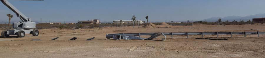
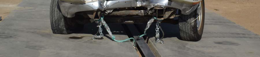
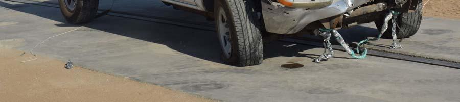
5 SECTION 1 INTRODUCTION 1.1 OBJECTIVES The objective of this crash test was to evaluate the impact performance of the Road Systems, Inc. SKT SP (15.24 m) System. This report presents the results of one (1) fullscale crash test conducted on one SKT SP (15.24 m) system. For this test, the terminal section was installed on the front end of a 34.3 m (112.5 ft.) length of guardrail. The test was conducted in accordance with instructions provided by the Virginia Department of Transportation. 1.2 TEST FACILITY This test was conducted at KARCO Engineering s test facility in Adelanto, California. The tow road is a continuous level surface constructed of reinforced concrete and measures 700 ft. long by 14 ft. wide by 6 in. thick. A steel rail is embedded in the road to provide vehicle guidance. Vehicle tow propulsion is provided by a 1 ton truck using a 1-to-2 pulley system. The test vehicle is towed to within 25 ft. of the barrier by a nylon rope clamped to a 3/8 in. steel cable. The clamp is released from the cable on contact with a cable release mechanism positioned to allow the test vehicle to proceed under its own momentum for a maximum of 25 ft. before impacting the barrier. 1.3 TEST ARTICLE The Road Systems, Inc. SKT SP (15.24 m) System is a standard post guardrail terminal/end treatment. The as-tested SKT SP (15.24 m) System consisted of one (1) SKT impact head, two (2) hinged posts, seven (7) standard I-beam line posts, two (2) W-beam rail panels, and one (1) cable anchor assembly. The terminal section was installed with a 50:1 flare and a rail height ranging from 705 mm (27.75 in.) to 730 mm (28.75 in.) per Virginia Department of Transportation (VDOT) Road and Bridge Standards. Post 1 consisted of one (1) 0.7 m (2.4 ft.) long top post constructed of 6.0 x 6.0 x steel tube and one (1) 1.8 m (6.0 ft.) long bottom post constructed of W6 x 15 steel I- beam. The posts were pinned together by a 229 mm (9.0 in.) long 16 mm (0.625 in.) diameter grade 5 hex head bolt, 16 mm (0.625 in.) diameter washers, and a 16 mm (0.625 in.) diameter nut. The bottom portion of post 1 had three (3) 13 mm (0.5 in.) thick plates welded at the top end, one (1) at each flange and one (1) on the upstream side of the post. A 356 mm (1.17 ft.) wide by 508 mm (1.7 ft.) tall by 5 mm (0.19 in.) thick soil plate was attached to the downstream side of the W6 x 15 steel I-beam, 152 mm (6.0 in.) down from the top end. 1
6 Post 2 consisted of one (1) 1.1 m (3.5 ft.) long bottom post and one (1) 0.9 m (2.8 ft.) long top post, both pieces were constructed of W6 x 9 steel I-beam. The bottom post had one (1) 178 mm (7.0 in.) long by 102 mm (4.0 in.) wide by in. (10 mm) thick plate welded to each flange. The top and bottom post were pinned together by an 18 mm (0.75 in.) diameter by 216 mm (8.5 in.) long ASTM A449 hex head bolt and an 18 mm (0.75 in.) diameter nut. The cable assembly was attached to post 1 with a 16 mm (0.625 in.) thick, 203 mm (8.0 in.) square steel bearing plate. The bearing plate had a 29 mm (1.125 in.) diameter hole drilled at the center of the plate through which the cable anchor was inserted and fastened with a washer and nut. The opposite end of the assembly was attached to the rail with a quick release cable anchor. The cable anchor attached to the rail with eight (8) 13 mm (0.5 in.) diameter shoulder bolts with washers, eight (8) 13 mm (0.5 in.) structural nuts, and eight (8) 13 mm (0.5 in.) structural washers. The cable anchor was composed of one (1) 6 mm (0.25 in.) thick cable release bracket and one (1) 13 mm (0.5 in.) cable release plate. The SKT impact head sits on the W-beam rail between post 1 and 2. The head assembly has a total length of 2.1 m (6.9 ft.). The front impacted section of the impact head is 510 mm (20.1 in.) wide by 510 mm (20.1 in.) tall. The rear section of the SKT impact head is composed of a chute that partially encloses the rail. The chute is 185 mm (7.3 in.) wide by 349 mm (13.75 in.) tall at the downstream end. The SKT impact head has a curved deflector plate composed of a 5 mm (0.19 in.) thick plate within the impact head. Two (2) 7.6 m (25.0 ft.) long rail panels are mounted to the posts of the terminal section with the splices located at post 5. The first rail panel was a 7.6 m (25.0 ft.) panel and composed of 12 Ga. W-beam. The leading edge of the rail had a series of thirteen (13) 0.5 x 4.0 slots. Three (3) 0.75 x 2.5 post slots were located at the center height of the rail. The posts slots were spaced 1.9 m (6.25 ft.) from one another on center. The rail also had eight (8) 19 mm (0.75 in.) diameter holes to attach the cable release bracket to the rail. The second rail was a standard 7.6 m (25.0 ft.) W-beam rail. 191 mm (7.5 in.) plastic offset blocks were used on post 3 through 9. For this test, the SKT SP (15.24 m) System was adjoined to the end of a 34.3 m (112.5 ft.) length of guardrail, measured from post 9 to post 27. The adjoining guardrail included a 3.8 m (12.5 ft.) long trailing end terminal treatment, measured from post 25 to post 27. The terminal s adjoining barrier consisted of seventeen (17) 1.8 m (6.0 ft.) long W6 x 8.5 standard I- beam line posts, one (1) 8 x 6 wood post with a soil plate and steel foundation tube, four (4) 7.6 m (25.0 ft.) long 12 Ga W-beam rail panels, one (1) 3.8 m (12.5 ft.) long 12 Ga W-beam rail panel, and one (1) cable anchor assembly. 191 mm (7.5 in.) plastic offset blocks were on all posts except the last wooden post. 2
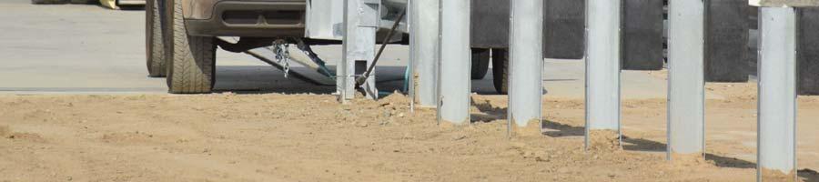
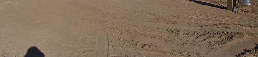
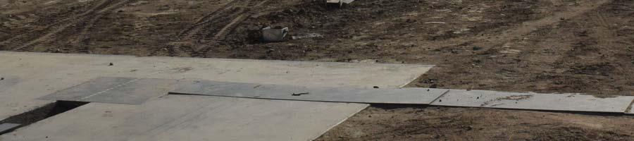
7 With the exception of post 1, 2 and the trailing end terminal post, the post were installed by drilling 0.3 m (1.0 ft.) diameter by 0.3 m (1.0 ft.) deep pilot holes and driving the posts into the soil. The first two posts as well as the trailing end terminal post were installed by drilling a 0.6 m (2.0 ft.) diameter hole. Post 1 and the trailing end terminal post were drilled to a depth of 1.8 m (6.0 ft.) while post 2 was drilled to a depth of 1.2 m (4.0 ft.). The holes were backfilled and compacted with a pneumatic compactor. Photographs of the as-tested unit and installation are available in Appendix A of this report. Manufacturer s drawings are available in Appendix D. The installation instructions are included on KARCO CD-R
8 SECTION 2 TEST PROCEDURE AND INSTRUMENTATION SUMMARY 2.1 TEST PROCEDURE To meet the recommended properties of the NCHRP 350 test vehicle requirements, a commercially available production model test vehicle was selected. The test vehicle was in free of major body damage and was not missing any structural components. The bumpers were standard equipment and were not modified for this test. All fluids were drained and the battery was removed. The NCHRP 350 recommended test vehicle properties are shown in Table 1. The 2000P test vehicle was used for this test. The 2000P test vehicle used for this test was a front engine model with rear wheel drive and an automatic transmission. Table 1. Recommended Properties of 700C, 820C and 2000P Test Vehicles PROPERTY 700C (Small Car) 820C (Small Car) 2000P (Pickup Truck) MASS (kg) Test Inertial Dummy Maximum Ballast Gross Static DIMENSIONS (cm) Wheelbase Front Overhang Overall Length Track Width (average) CENTER OF MASS LOCATION (cm) Aft of Front Axle Above Ground LOCATION OF ENGINE Front Front Front LOCATION OF DRIVE AXLE Front Front Rear TYPE OF TRANSMISSION Manual or Automatic Manual or Automatic Manual or Automatic 4
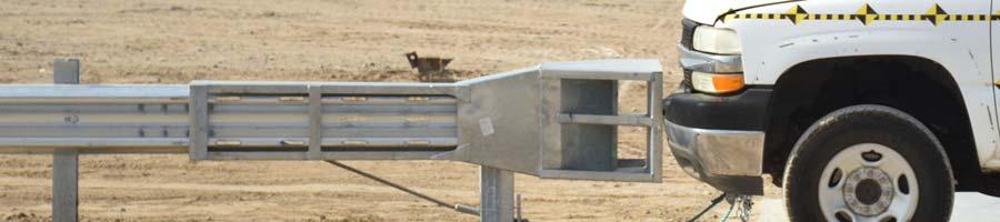
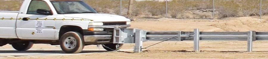
9 2.2 CRASH TEST SET UP A full-scale crash test was conducted to evaluate the impact performance of the SKT SP (15.24 m) System. The test conditions were as follows: A 2000 kg (4409 lb.) pickup truck approaching the test article at a nominal speed of 100 km/h (62 mph) with a critical impact angle of 5. The test article was installed so that the vehicle centerline intersected the leading edge of the W-beam rail. 2.3 TEST INSTRUMENTATION AND DATA ACQUISITION PROCEDURES All data acquisition for this certification test was performed in accordance with the NCHRP 350 Recommended Procedure requirements Test Vehicle Instrumentation: The test vehicle was instrumented with one (1) tri-axial accelerometer and one tri-axial angular rate sensor. Both the accelerometer and the angular rate sensor were installed with a 5 cm radial of the vehicle s longitudinal and lateral center of gravity. The accelerometers measured longitudinal (x), lateral (y) and vertical (z) acceleration. The angular rate sensors measured vehicle roll, pitch and yaw. Data was recorded using the onboard TDAS. Data was linked to a personal computer and processed using the TDAS Control software. All equipment used in this test meets the requirements of SAE J Calibration: All instrumentation used in this test has been calibrated through standards traceable to NIST and is maintained in a calibrated condition TDAS Software: The software utilized in this system is written in National Instruments Lab Windows/CVI (C, Visual Interface) programming language, which is a Windows based software package with emphasis on ease of use and good engineering test practices SAE Compatibility: The software contains standard point and click processing options for selecting Society of Automotive Engineers (SAE) class post filters and calculating the required integrals, resultants, Head Injury Criteria (HIC), clips, and other data processing parameters that may be required Measurement Uncertainty: Measurement uncertainties have been determined for pertinent values affecting the results of this test. KARCO maintains these uncertainty budgets, which are available upon request, but are not included in this report. In certain cases the nature of the test method may preclude rigorous and statistically valid calculation of uncertainty of measurement. In these cases KARCO attempts to identify the components of uncertainty and make a reasonable estimation. Reasonable estimation is based on knowledge of the performance of the method and on the measurement scope and makes use of, for example, previous experience and validation data. 5
10 2.3.5 Photographic Documentation: Photographic documentation of this test included a minimum of two (2) real-time video camera at 30 frames per second (fps), and six (6) highspeed color digital video cameras at 1000 fps All high-speed cameras were activated by a pressure-sensitive tape switch, which was positioned on the test article to indicate the instant of contact (time zero). A digital still camera was used for documenting the pre- and post-test condition of the test vehicle and the SKT SP (15.24 m) System Anthropomorphic Test Device: An Anthropomorphic Test Device (ATD) was not used for this test. 6
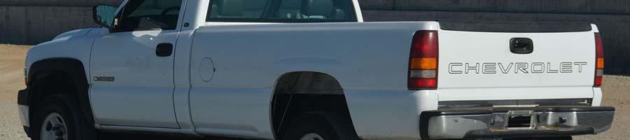
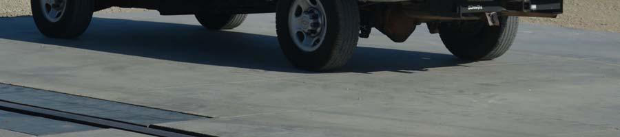
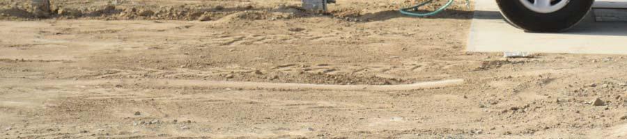
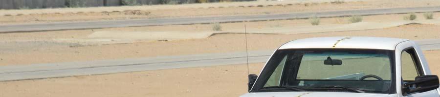
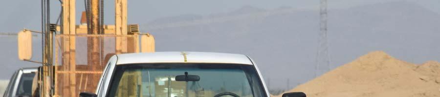
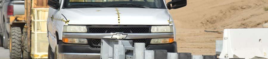
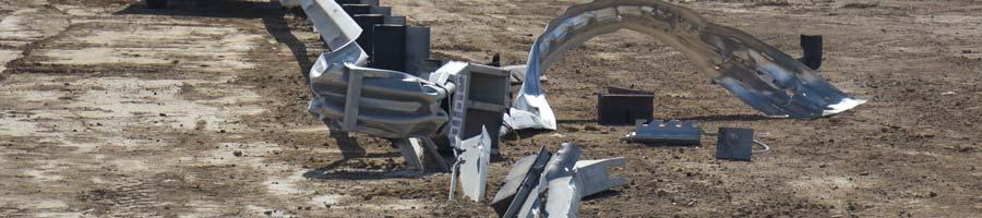
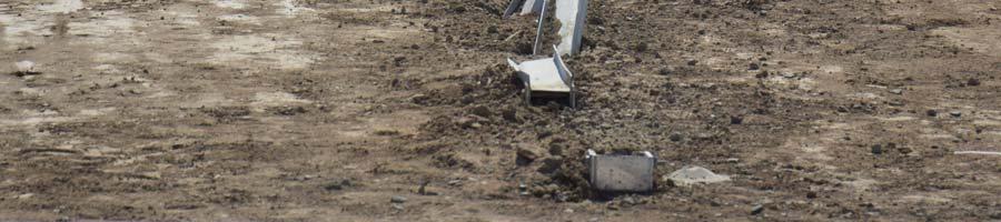
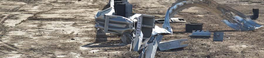
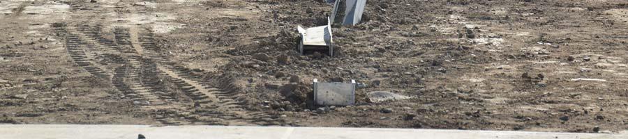
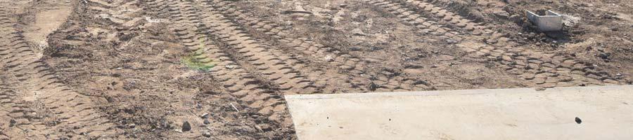
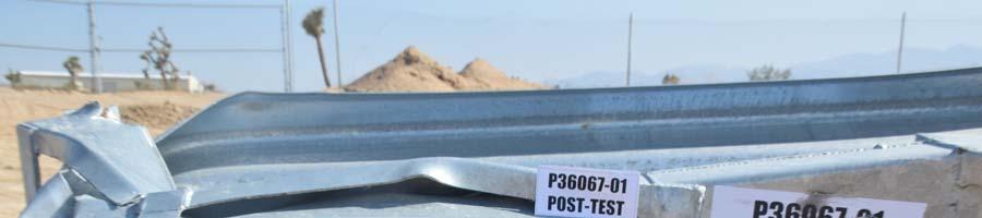
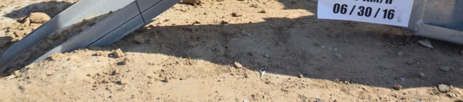
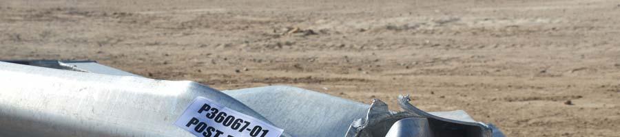
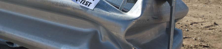
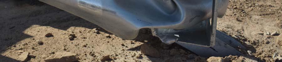
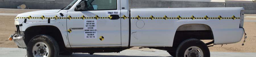
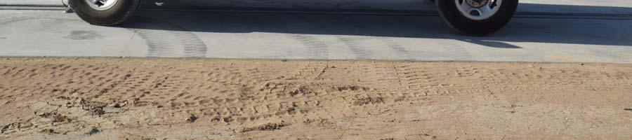
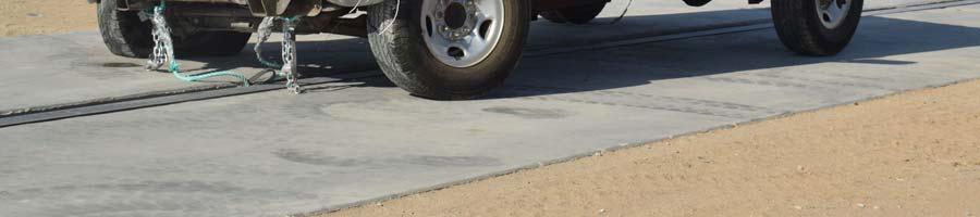
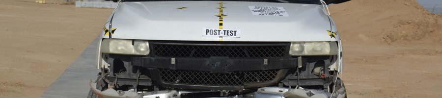
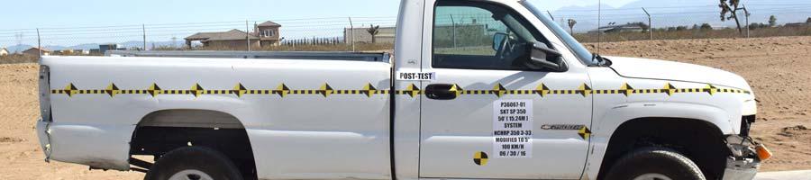
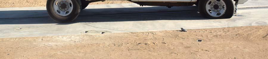
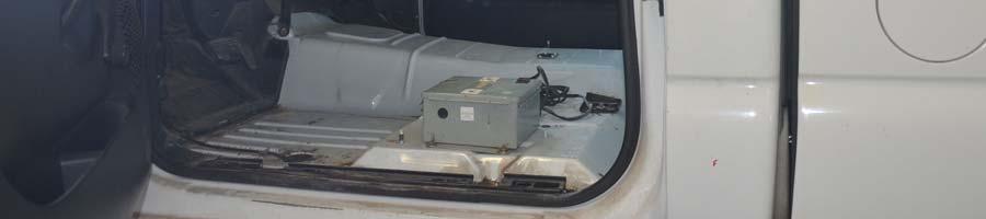
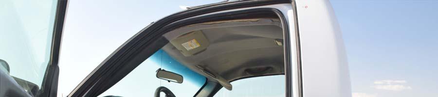
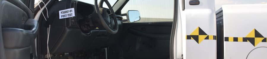
11 SECTION 3 TEST RESULTS This 100 km/h (62 mph) impact crash test was conducted using a 2002 Chevrolet 2500 pickup truck to evaluate the impact performance of the SKT SP (15.24 m) System. The test article was installed at an angle of 5 relative to the test vehicle s direction of travel, with the vehicle centerline intersecting the leading edge of the W-beam rail. This crash test was documented by two (2) real-time and six (6) high-speed video cameras. Pre- and post-test photographs of the test vehicle and test article can be found in Appendix A. The test was conducted on June 30, The as-tested test inertial weight of the vehicle was 2,042.5 kg (4,502.8 lbs.). The height of the front bumper was 415 mm (16.3 in.) to the lower edge and 605 mm (23.8 in.) to the upper edge. Additional dimensions and test vehicle information are presented in Data Sheets No. 1 and 2. The test vehicle impacted the SKT SP (15.24 m) System at a velocity of km/h (61.18 mph). The test vehicle impacted the SKT impact head and pushed it down the guardrail past the first 6 posts. After the SKT extruder head chute passed post 6 the rail buckled and the vehicle continued to the non-traffic side of the article. The test vehicle impacted the extruded section of rail and began tracking back towards the article. The test vehicle impacted the length of need section near post 17 and subsequently rode up the non-traffic side of the article. The vehicle came to rest with its left side wheels on the traffic side of the article 43.3 m (421.1 ft.) downstream from its position at the point of impact. The test article sustained damage from post 1 through post 6. Post 1 top broke away at the connection bolt, post 2 folded to the ground while post 3 through 6 bent towards the ground. The chute on the SKT impact head sustained deformation and a tear on its downstream end. The length of need section was also damaged from post 16 through 23. An overhead illustration of the test vehicle and test article in their pre-test and post-test condition is shown in figure 2 in Appendix D. Sequential photographs of the test sequence are shown on Data Sheet 4. The vehicle sustained damage to the front end including the front bumper and grill as a result of the impact with the SKT SP (15.24 m) System. The front right tire was also punctured. The occupant compartment was not penetrated as a result of the impact. A summary of the electronic data is presented in Data Sheet No. 6; data plots are presented in Appendix B. 7
12 SECTION 4 DATA SHEETS Test Article: SKT SP (15.24 m) System Project No. P Test Program: 100 km/h 5 Guardrail Terminal Impact Test Test Date: 06/30/16 CONVERSION FACTORS Quantity Typical Application Std Units Metric Unit Multiply By Mass Vehicle Weight lb kg Linear Velocity Impact Velocity miles/hr km/hr Length or Distance Measurements in mm 25.4 Volume Fuel Systems gal liter Volume Small Fluids oz ml Pressure Tire Pressures lbf/in 2 kpa Temperature General Use o F o C =(Tf -32)/1.8 Force Dynamic Forces lbf N Moment Torque lbf-ft N m
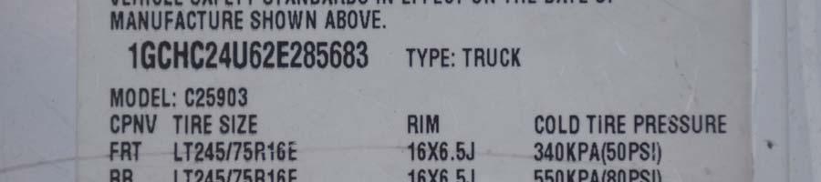
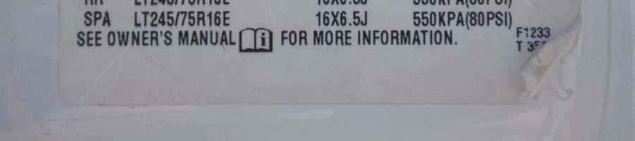
13 DATA SHEET 1 TEST VEHICLE INFORMATION Test Article: SKT SP (15.24 m) System Project No. P Test Program: 100 km/h 5 Guardrail Terminal Impact Test Test Date: 06/30/16 TEST VEHICLE INFORMATION Make Chevrolet Cylinders V8 Model 2500 Engine Displacement (L) 6.0 Body Style 2-Door Truck Engine Placement Longitudinal VIN 1GCHC24U62E Fuel Type Gasoline Color White Transmission Automatic Odometer Reading (mi) 287,616 Final Drive Rear Previous Damage to Vehicle Minor Scratches DATA FROM CERTIFICATION LABEL GVWR (kg) 4173 Manufactured By General Motors Corp GAWR Front (kg) 2000 Date of Manufacture May-02 GAWR Rear (kg) 2760 TEST VEHICLE WEIGHTS As Received (kg) Test Inertial (kg) Gross Static (kg) Front Rear Total Front Rear Total Front Rear Total Left Right Ratio (%) Total As Received (lb) Test Inertial (lb) Gross Static (lb) Front Rear Total Front Rear Total Front Rear Total Left Right Ratio (%) Total
14 DATA SHEET 2 TEST VEHICLE GEOMETRY Test Article: SKT SP (15.24 m) System Project No. P Test Program: 100 km/h 5 Guardrail Terminal Impact Test Test Date: 06/30/16 TEST VEHICLE GEOMETRY mm in. mm in. mm in. mm in. A E J N B F K O C G L P D H M Q
15 DATA SHEET 3 OCCUPANT COMPARTMENT DEFORMATION INDEX Test Article: SKT SP (15.24 m) System Project No. P Test Program: 100 km/h 5 Guardrail Terminal Impact Test Test Date: 06/30/16 The seven subindicies a, b, c, d, e, f and g indicate the percentage of reduction of seven interior dimensions shown on the following figure: where, a = distance between the dashboard and a reference point at the rear of the occupant compartment, such as top of rear seat, or the rear part of the cab on a pickup; b = distance between the roof and the floor panel; c = distance between a reference point at the rear of the occupant compartment and the motor panel; d = distance between the lower dashboard and the floor panel; e = interior width; f = distance between the lower edge of right window and the upper edge of left window; and g = distance between the lower edge of left window and the upper edge of right window Sub-Indices Pre-Test Post-Test Percent mm in. mm in. Reduction A % B % C % D % E % F % G % Max Deformation % OCDI FS Comments: None 11
16 DATA SHEET 4 SUMMARY OF RESULTS Test Article: SKT SP (15.24 m) System Project No.: P Test Program: 100 km/h 5 Guardrail Terminal Impact Test Test Date: 06/30/16 0 ms 200 ms 400 ms 700 ms 1000 ms 2900 ms GENERAL INFORMATION OCCUPANT RISK VALUES TEST AGENCY KARCO Engineering, LLC. FLAIL SPACE VELOCITY (m/s) TEST ARTICLE X DIRECTION 5.0 TYPE Terminal Y DIRECTION 0.4 TERMINAL LENGTH m (50.0 ft.) THIV (Optional) (m/s) 5.0 ADJOINING BARRIER LENGTH m (112.5 ft.) RIDEDOWN ACCELERATION (g) TEST VEHICLE X DIRECTION -5.2 TYPE Production Model Y DIRECTION 4.1 DESIGNATION 2000P PHD (Optional) (g) 6.3 MODEL Chevrolet 2500 ASI (Optional) 0.41 MASS (CURB) 2,360.0 kg (5,202.8 lbs) VEHICLE DAMAGE MASS (TEST INERTIAL) 2,042.5 kg (4,502.8 lbs) INTERIOR MASS (GROSS STATIC) 2,042.5 kg (4,502.8 lbs) OCDI FS IMPACT CONDITIONS POST-IMPACT VEHICULAR BEHAVIOR VELOCITY (km/h) km/h (61.18 mph) MAXIMUM ROLL ANGLE ( ) 7.3 ANGLE ( ) 5.4 MAXIMUM PITCH ANGLE ( ) IMPACT SEVERITY (kj) MAXIMUM YAW ANGLE ( ) Terminal Length measured from Post 1 to Post 9 2 Adjoining Barrier Length measured from Post 9 to Post 27 12
17 DATA SHEET 5 IMPACT CONDITIONS Test Article: SKT SP (15.24 m) System Project No. P Test Program: 100 km/h 5 Guardrail Terminal Impact Test Test Date: 06/30/16 Item Value Test Time 4:13 PM Temperature ( C) 37.8 * Wind Velocity (km/h) 12.9 * Wind Direction South * Impact Speed (km/h) *Information provided for reference only 13
18 DATA SHEET 6 TEST DATA SUMMARY Test Article: SKT SP (15.24 m) System Project No. P Test Program: 100 km/h 5 Guardrail Terminal Impact Test Test Date: 06/30/16 TEST VEHICLE DATA SUMMARY Tested Parameter Axis Units Max Time (ms) Min Time (ms) Vehicle Impact Velocity X m/s 27.3 Flail Space Velocity X m/s Flail Space Velocity Y m/s Ridedown Acceleration X g Ridedown Acceleration Y g TEST VEHICLE ACCELEROMETER PEAK DATA Location Axis Units Max Time (ms) Min Time (ms) Vehicle CG X g Vehicle CG Y g Vehicle CG Z g
19 APPENDIX A PHOTOGRAPHS A
20 LIST OF PHOTOGRAPHS Figure Page 1 Test Article, As-Received A-1 2 Test Article, As-Received A-1 3 Test Vehicle, As-Received A-2 4 Test Vehicle, As-Received A-2 5 Test Setup A-3 6 Test Setup Close-Up A-3 7 Test Setup A-4 8 Test Setup Close-Up A-4 9 Test Setup A-5 10 Test Setup Close-Up A-5 11 Test Setup A-6 12 Test Setup Close-Up A-6 13 Test Setup A-7 14 Test Setup Close-Up A-7 15 Post-Test A-8 16 Post-Test A-8 17 Pre-Test Front View of Test Article A-9 18 Post-Test Front View of Test Article A-9 19 Pre-Test Right Front ¾ View of Test Article A Post-Test Right Front ¾ View of Test Article A Pre-Test Right View of Test Article A Post-Test Right View of Test Article A Pre-Test Right Rear ¾ View of Test Article A Post-Test Right Rear ¾ View of Test Article A Pre-Test Rear View of Test Article A Post-Test Rear View of Test Article A Pre-Test Left Rear ¾ View of Test Article A Post-Test Left Rear ¾ View of Test Article A Pre-Test Left View of Test Article A Post-Test Left View of Test Article A Pre-Test Left Front ¾ View of Test Article A Post-Test Left Front ¾ View of Test Article A Test Article Damage A Test Article Damage A-17 A-i
21 LIST OF PHOTOGRAPHS (CONTINUED) Figure Page 35 Test Article Damage A Test Article Damage A Pre-Test Left View of Test Vehicle A Post-Test Left View of Test Vehicle A Pre-Test Left Front ¾ View of Test Vehicle A Post-Test Left Front ¾ View of Test Vehicle A Pre-Test Front View of Test Vehicle A Post-Test Front View of Test Vehicle A Pre-Test Right Front ¾ View of Test Vehicle A Post-Test Right Front ¾ View of Test Vehicle A Pre-Test Right View of Test Vehicle A Post-Test Right View of Test Vehicle A Pre-Test Windshield A Post-Test Windshield A Pre-Test View of Driver Side Occupant Compartment A Post-Test View of Driver Side Occupant Compartment A Pre-Test View of Driver Side Floorpan A Post-Test View of Driver Side Floorpan A Pre-Test View of Passenger Side Occupant Compartment A Post-Test View of Passenger Side Occupant Compartment A Pre-Test View of Passenger Side Floorpan A Post-Test View of Passenger Side Floorpan A Test Vehicle Manufacturer s Label A-29 A-ii


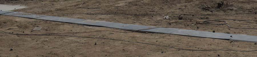
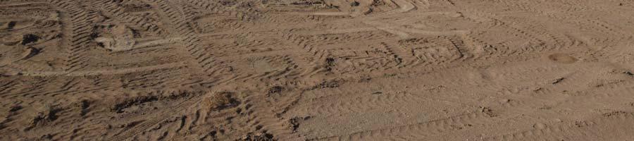
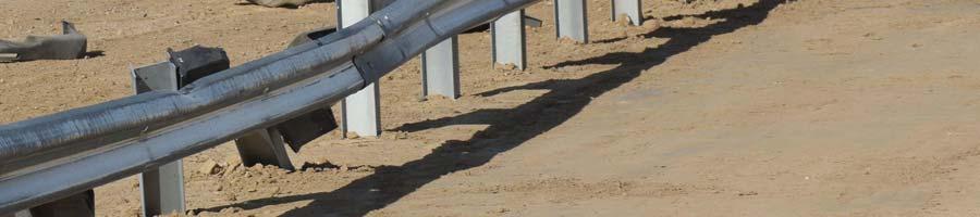
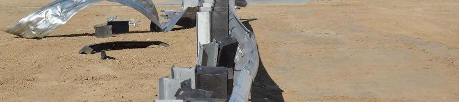
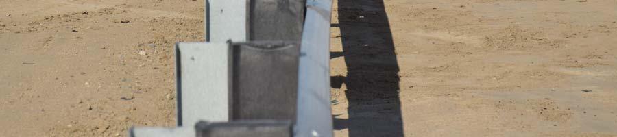
22 FIGURE 1. Test Article, As Received FIGURE 2. Test Article, As Received A-1


23 FIGURE 3. Test Vehicle, As Received FIGURE 4. Test Vehicle, As Received A-2


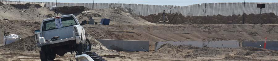
24 FIGURE 5. Test Setup FIGURE 6. Test Setup Close-Up A-3


25 FIGURE 7. Test Setup FIGURE 8. Test Setup Close-Up A-4


26 FIGURE 9. Test Setup FIGURE 10. Test Setup Close-Up A-5


27 FIGURE 11. Test Setup FIGURE 12. Test Setup Close-Up A-6


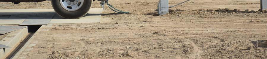
28 FIGURE 13. Test Setup FIGURE 14. Test Setup Close-Up A-7


29 FIGURE 15. Post-Test FIGURE 16. Post-Test A-8


30 FIGURE 17. Pre-Test Front View of Test Article FIGURE 18. Post-Test Front View of Test Article A-9


31 FIGURE 19. Pre-Test Right Front ¾ View of Test Article FIGURE 20. Post-Test Right Front ¾ View of Test Article A-10


32 FIGURE 21. Pre-Test Right View of Test Article FIGURE 22. Post-Test Right View of Test Article A-11


33 FIGURE 23. Pre-Test Right Rear ¾ View of Test Article FIGURE 24. Post-Test Right Rear ¾ View of Test Article A-12


34 FIGURE 25. Pre-Test Rear View of Test Article FIGURE 26. Post-Test Rear View of Test Article A-13


35 FIGURE 27. Pre-Test Left Rear ¾ View of Test Article FIGURE 28. Post-Test Left Rear ¾ View of Test Article A-14


36 FIGURE 29. Pre-Test Left View of Test Article FIGURE 30. Post-Test Left View of Test Article A-15


37 FIGURE 31. Pre-Test Left Front ¾ View of Test Article FIGURE 32. Post-Test Left Front ¾ View of Test Article A-16


38 FIGURE 33. Test Article Damage FIGURE 34. Test Article Damage A-17


39 FIGURE 35. Test Article Damage FIGURE 36. Test Article Damage A-18


40 FIGURE 37. Pre-Test Left View of Test Vehicle FIGURE 38. Post-Test Left View of Test Vehicle A-19


41 FIGURE 39. Pre-Test Left Front ¾ View of Test Vehicle FIGURE 40. Post-Test Left Front ¾ View of Test Vehicle A-20


42 FIGURE 41. Pre-Test Front View of Test Vehicle FIGURE 42. Post-Test Front View of Test Vehicle A-21


43 FIGURE 43. Pre-Test Right Front ¾ View of Test Vehicle FIGURE 44. Post-Test Right Front ¾ View of Test Vehicle A-22


44 FIGURE 45. Pre-Test Right View of Test Vehicle FIGURE 46. Post-Test Right View of Test Vehicle A-23

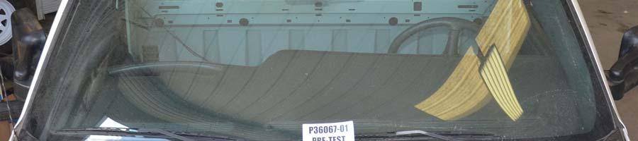

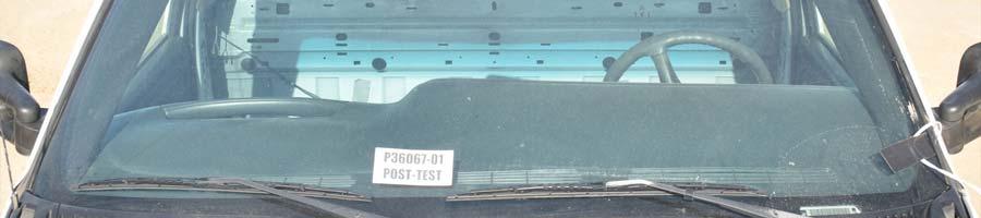
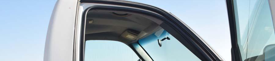
45 FIGURE 47. Pre-Test Windshield FIGURE 48. Post-Test Windshield A-24


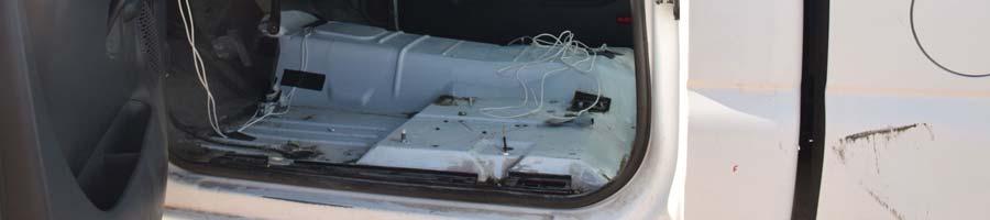
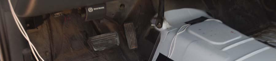
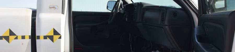
46 FIGURE 49. Pre-Test Driver Side Occupant Compartment FIGURE 50. Post-Test Driver Side Occupant Compartment A-25


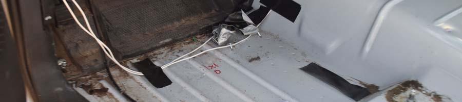

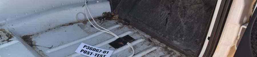
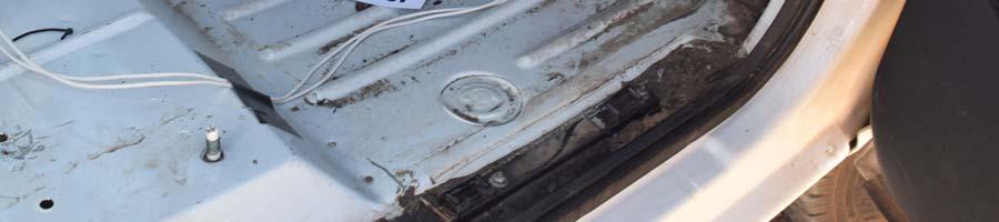
47 FIGURE 51. Post-Test Driver Side Floorpan FIGURE 52. Post-Test Driver Side Floorpan A-26


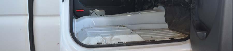

48 FIGURE 53. Pre-Test Passenger Side Occupant Compartment FIGURE 54. Post-Test Passenger Side Occupant Compartment A-27


49 FIGURE 55. Pre-Test Passenger Side Floorpan FIGURE 56. Post-Test Passenger Side Floorpan A-28

50 FIGURE 57. Test Vehicle Manufacturer s Label A-29
51 APPENDIX B DATA PLOTS B
52 LIST OF DATA PLOTS Plot Page 1 Test Vehicle CG X B-1 2 Test Vehicle CG X Moving Average B-1 3 Test Vehicle CG X Velocity B-1 4 Test Vehicle CG X Displacement B-1 5 Test Vehicle CG Y B-2 6 Test Vehicle CG Y Moving Average B-2 7 Test Vehicle CG Y Velocity B-2 8 Test Vehicle CG Y Displacement B-2 9 Test Vehicle CG Z B-3 10 Test Vehicle Accident Severity Index B-3 11 Test Vehicle Roll Angle B-4 12 Test Vehicle Yaw Angle B-4 13 Test Vehicle Pitch Angle B-4 B-i
53 Test Article: SKT SP ' (15.24 m) System Project No: P Test Program: 100 km/h 5 Guardrail Terminal Impact Test Test Date.: 6/30/16 5 Acceleration (g) Curve Description Test Vehicle CG X Plot No. Type SAE Class Units 001 FIL 60 g Max Time Min Time Time (ms) 3 0 Acceleration (g) Curve Description Test Vehicle CG X Moving Average Plot No. Type SAE Class Units 002 AVG 180 g Max Time Min Time Time (ms) Velocity (m/s) Curve Description Test Vehicle CG X Velocity Plot No. Type SAE Class Units 003 IN1 180 m/sec Max Time Min Time Time (ms) 8 Displacement (m) Curve Description Test Vehicle CG X Displacement Plot No. Type SAE Class Units 004 IN2 180 Meters Max Time Min Time Vehicle CG X Displacement Occupant X Displacement Time (ms) B-1
54 Test Article: SKT SP ' (15.24 m) System Project No: P Test Program: 100 km/h 5 Guardrail Terminal Impact Test Test Date.: 6/30/16 10 Acceleration (g) Curve Description Test Vehicle CG Y Plot No. Type SAE Class Units 005 FIL 60 g Max Time Min Time Time (ms) 6 Acceleration (g) Curve Description Test Vehicle CG Y Moving Average Plot No. Type SAE Class Units 006 AVG 180 g Max Time Min Time Time (ms) 2 Velocity (m/s) Curve Description Test Vehicle CG Y Velocity Plot No. Type SAE Class Units 007 IN1 180 m/sec Max Time Min Time Time (ms) 2 Displacement (m) Curve Description Test Vehicle CG Y Displacement Plot No. Type SAE Class Units 008 IN2 180 Meters Max Time Min Time Vehicle CG Y Displacement Occupant Y Displacement Time (ms) B-2
55 Test Article: SKT SP ' (15.24 m) System Project No: P Test Program: 100 km/h 5 Guardrail Terminal Impact Test Test Date.: 6/30/ Acceleration (g) Curve Description Test Vehicle CG Z Plot No. Type SAE Class Units 009 FIL 60 g Max Time Min Time Time (ms) 0.75 ASI Time (ms) Curve Description Test Vehicle Accident Severity Index Plot No. Type SAE Class Units 010 ASI 180 ASI Max Time Min Time B-3
56 Test Article: SKT SP ' (15.24 m) System Project No: P Test Program: 100 km/h 5 Guardrail Terminal Impact Test Test Date.: 6/30/ Angle (deg) Curve Description Test Vehicle Roll Angle Plot No. Type SAE Class Units 011 IN1 180 Degrees Max Time Min Time Time (ms) 10 Angle (deg) Curve Description Test Vehicle Yaw Angle Plot No. Type SAE Class Units 012 IN1 180 Degrees Max Time Min Time Time (ms) 5 Angle (deg) Time (ms) Curve Description Test Vehicle Pitch Angle Plot No. Type SAE Class Units 013 IN1 180 Degrees Max Time Min Time B-4
57 APPENDIX C INSTRUMENTATION C
58 DATA ACQUISITION INFORMATION Test Article: SKT SP (15.24 m) System Project No. P Test Program: 100 km/h 5 Guardrail Terminal Impact Test Test Date: 06/30/16 VEHICLE INSTRUMENTATION CH Location Axis Ident. No. Description MFR Model Units 1 Vehicle CG X P51708 Accel, Half Bridge Endevco 2000G g 2 Vehicle CG Y P51700 Accel, Half Bridge Endevco 2000G g 3 Vehicle CG Z P51696 Accel, Half Bridge Endevco 2000G g 4 Vehicle CG Yaw ARS8486 Rate Gyro DTS ARS-18K Deg/s 5 Vehicle CG Pitch ARS8532 Rate Gyro DTS ARS-18K Deg/s 6 Vehicle CG Roll ARS8537 Rate Gyro DTS ARS-18K Deg/s C-1
59 APPENDIX D MANUFACTURER DOCUMENTS D
60 LIST OF FIGURES Figure Page 1 Manufacturer s Drawing D-1 2 Overhead Illustration D-2 D-i
61 FIGURE 1. Manufacturer s Drawing D-1
62 FIGURE 2. Overhead Illustration FINAL PAGE OF REPORT D-2
FAAC International, Inc.
 TEST REPORT FOR: FAAC International, Inc. J 355 HA M30 (K4) Bollard TESTED TO: ASTM F 2656-07 Standard Test Method for Vehicle Crash Testing of Perimeter Barriers Test M30 PREPARED FOR: FAAC International,
CRASH TEST REPORT FOR PERIMETER BARRIERS AND GATES TESTED TO SD-STD-02.01, REVISION A, MARCH Anti-Ram Bollards
 CRASH TEST REPORT FOR PERIMETER BARRIERS AND GATES TESTED TO SD-STD-02.01, REVISION A, MARCH 2003 Anti-Ram Bollards Prepared for: RSA Protective Technologies, LLC 1573 Mimosa Court Upland, CA 91784 Test
RSA Protective Technologies
 TEST REPORT FOR: RSA Protective Technologies K12 Surface Mounted Bollard System TESTED TO: ASTM F 2656-07 Standard Test Method for Vehicle Crash Testing of Perimeter Barriers Test M50 PREPARED FOR: Battelle
The Center for Auto Safety
 TEST REPORT FOR: The Center for Auto Safety 40 mph Vehicle to Vehicle 30% Offset Rear Impact 40 mph Vehicle to Vehicle 30% Offset Rear Impact 1996 Jeep Grand Cherokee Limited 1988 Ford Taurus PREPARED
The Center for Auto Safety
 TEST REPORT FOR: The Center for Auto Safety 50 mph Vehicle to Vehicle 30% Offset Rear Impact 50 mph Vehicle to Vehicle 30% Offset Rear Impact 1999 Jeep Grand Cherokee Laredo 1987 Ford Taurus PREPARED FOR:
STI Project: Barrier Systems, Inc. RTS-QMB Longitudinal Barrier. Page 38 of 40 QBOR1. Appendix F (Continued) Figure F-3
 Figure F-3") Barrier Systems, Inc. RTS-QMB Longitudinal Barrier STI Project: QBOR1 Page 38 of 40 Appendix F (Continued) Figure F-3 t=.500sec 115 meters overall 37.1 Impact Severity (kj).. 141.6 Angle (deg).. 25 Speed
Barrier Systems, Inc. RTS-QMB Longitudinal Barrier STI Project: QBOR1 Page 38 of 40 Appendix F (Continued) Figure F-3 t=.500sec 115 meters overall 37.1 Impact Severity (kj).. 141.6 Angle (deg).. 25 Speed
Manual for Assessing Safety Hardware
 American Association of State Highway and Transportation Officials Manual for Assessing Safety Hardware 2009 vii PREFACE Effective traffic barrier systems, end treatments, crash cushions, breakaway devices,
REPORT NUMBER TR-P NC SAFETY COMPLIANCE TESTING FOR FMVSS 124 ACCELERATOR CONTROL SYSTEMS
 REPORT NUMBER TR-P299-3-NC SAFETY COMPLIANCE TESTING FOR FMVSS 124 ACCELERATOR CONTROL SYSTEMS NISSAN MOTOR CORPORATION 29 NISSAN ROGUE 5-DOOR MPV NHTSA NUMBER: C95 PREPARED BY: KARCO ENGINEERING, LLC.
A MASH Compliant W-Beam Median Guardrail System
 0 0 0 0 0 A MASH Compliant W-Beam Median Guardrail System By A. Y. Abu-Odeh, R. P. Bligh, W. Odell, A. Meza, and W. L. Menges Submitted: July 0, 0 Word Count:, + ( figures + tables=,000) =, words Authors:
July 10, Refer to: HSA-10/CC-78A
 July 10, 2003 Refer to: HSA-10/CC-78A Barry D. Stephens, P.E. Senior Vice President of Engineering ENERGY ABSORPTION Systems, Inc. 3617 Cincinnati Avenue Rocklin, California 95765 Dear Mr. Stephens: Your
CRASH TESTING OF RSA/K&C ANTI-RAM FOUNDATION BOLLARD PAD IN ACCORDANCE WITH U.S. DEPARTMENT OF STATE DIPLOMATIC SECURITY SD-STD-02.
 CRASH TESTING OF RSA/K&C ANTI-RAM FOUNDATION BOLLARD PAD IN ACCORDANCE WITH U.S. DEPARTMENT OF STATE DIPLOMATIC SECURITY SD-STD-02.01 REVISION A Prepared for RSA Protective Technologies, LLC FINAL REPORT
February 8, In Reply Refer To: HSSD/CC-104
 February 8, 2008 200 New Jersey Avenue, SE. Washington, DC 20590 In Reply Refer To: HSSD/CC-04 Barry D. Stephens, P.E. Sr. Vice President Engineering Energy Absorption Systems, Inc. 367 Cincinnati Avenue
Appendix D. Figure D-1. ENCLOSURE 1 (4 Pages) SafeGuard TM Gate System
 SafeGuard TM Gate System") Appendix D Figure D-1 SafeGuard TM Gate System ENCLOSURE 1 (4 Pages) Appendix D (Continued) Figure D-4 SafeGuard TM Gate System Appendix D (Continued) Figure D-9 SafeGuardTM Gate System Page D-9 Figure
Appendix D Figure D-1 SafeGuard TM Gate System ENCLOSURE 1 (4 Pages) Appendix D (Continued) Figure D-4 SafeGuard TM Gate System Appendix D (Continued) Figure D-9 SafeGuardTM Gate System Page D-9 Figure
NCHRP Report 350 Test 4-12 of the Modified Thrie Beam Guardrail
 NCHRP Report 350 Test 4-12 of the Modified Thrie Beam Guardrail PUBLICATION NO. FHWA-RD-99-065 DECEMBER 1999 Research, Development, and Technology Turner-Fairbank Highway Research Center 6300 Georgetown
ASTM F TEST M30 ON THE RSS-3000 DROP BEAM SYSTEM
 Proving Ground Test Report No.: 510602-RSS3 Test Report Date: January 2014 ASTM F2656-07 TEST M30 ON THE RSS-3000 DROP BEAM SYSTEM by Dean C. Alberson, Ph.D., P.E. Research Engineer Michael S. Brackin,
COMPLIANCE TESTING FOR FMVSS 207 SEATING SYSTEMS
 REPORT NO. COMPLIANCE TESTING FOR FMVSS 207 SEATING SYSTEMS 2008 CHEVROLET IMPALA 4-DOOR NHTSA NO.C80102 PREPARED BY: KARCO ENGINEERING, LLC 9270 HOLLY ROAD ADELANTO, CALIFORNIA 92301 September 24, 2008
Form DOT F (8-72) Texas Transportation Institute The Texas A&M University System College Station, Texas
 Texas Transportation Institute The Texas A&M University System College Station, Texas") 1. Report No. FHWA/TX-02/4162-1 Technical Report Documentation Page 2. Government Accession No. 3. Recipient's Catalog No. 4. Title and Subtitle EVALUATION OF TEXAS GRID-SLOT PORTABLE CONCRETE BARRIER
1. Report No. FHWA/TX-02/4162-1 Technical Report Documentation Page 2. Government Accession No. 3. Recipient's Catalog No. 4. Title and Subtitle EVALUATION OF TEXAS GRID-SLOT PORTABLE CONCRETE BARRIER
JRS Dynamic Rollover Test Chevrolet Malibu
 Page 1 of 61 JRS Dynamic Rollover Test 2009 Chevrolet Malibu Sponsored By: Automotive Safety Research Institute Charlottesville, VA. Vehicle Donated by: State Farm Insurance Company Chicago, IL. Introduction
JRS Dynamic Rollover Test Toyota Camry
 Page 1 of 60 JRS Dynamic Rollover Test 2007 Toyota Camry Hybrid Version Sponsored By: Automotive Safety Research Institute Charlottesville, VA. Introduction Page 2 of 60 Center for Injury Research conducted
CRASH TEST AND EVALUATION OF TEMPORARY WOOD SIGN SUPPORT SYSTEM FOR LARGE GUIDE SIGNS
 TTI: 9-1002-15 CRASH TEST AND EVALUATION OF TEMPORARY WOOD SIGN SUPPORT SYSTEM FOR LARGE GUIDE SIGNS ISO 17025 Laboratory Testing Certificate # 2821.01 Crash testing performed at: TTI Proving Ground 3100
JRS Dynamic Rollover Test Scion xb
 Page 1 of 57 JRS Dynamic Rollover Test 2008 Scion xb Sponsored By: Automotive Safety Research Institute Charlottesville, VA. Introduction Page 2 of 57 Center for Injury Research conducted a JRS dynamic
Texas Transportation Institute The Texas A&M University System College Station, Texas
 1. Report No. FHWA/TX-05/9-8132-P7 4. Title and Subtitle TL-4 CRASH TESTING OF THE F411 BRIDGE RAIL 2. Government Accession No. 3. Recipient's Catalog No. 5. Report Date October 2004 Technical Report Documentation
JRS Dynamic Rollover Test Toyota Prius
 Page 1 of 62 JRS Dynamic Rollover Test 2010 Toyota Prius Sponsored By: Automotive Safety Research Institute Charlottesville, VA. Vehicle Donated by: State Farm Insurance Company Chicago, IL. Introduction
Electronic Reporting
 Electronic Reporting Test TB31 of BS EN 1317 Parts 1 & 2 Test Number: TRL068 Trief Kerb and Pavement (Opinions and interpretations do not form part of this report.) TEST REPORT VIDEO FOOTAGE TRL068, Trief
REPORT NO. TR-P NC SAFETY COMPLIANCE TESTING FOR FMVSS 223 REAR IMPACT GUARDS 2007 TRANSFREIGHT TECHNOLOGY NHTSA NO.
 REPORT NO. SAFETY COMPLIANCE TESTING FOR FMVSS 223 REAR IMPACT GUARDS 2007 TRANSFREIGHT TECHNOLOGY NHTSA NO. RIG 009 PREPARED BY: KARCO ENGINEERING, LLC. 9270 HOLLY ROAD ADELANTO, CALIFORNIA 92301 SEPTEMBER
Product Specification. ABSORB 350 TM TL-2 Non-Redirective, Gating, Crash Cushion Applied to Quickchange Moveable Barrier
 TB 000612 Rev. 0 Page 1 of 9 Product Specification ABSORB 350 TM TL-2 Non-Redirective, Gating, Crash Cushion Applied to Quickchange Moveable Barrier I. General The ABSORB 350 TM TL-2 System is a Non-Redirective,
CRASH TEST AND EVALUATION OF 3-FT MOUNTING HEIGHT SIGN SUPPORT SYSTEM
 TTI: 9-1002-15 CRASH TEST AND EVALUATION OF 3-FT MOUNTING HEIGHT SIGN SUPPORT SYSTEM ISO 17025 Laboratory Testing Certificate # 2821.01 Crash testing performed at: TTI Proving Ground 3100 SH 47, Building
REPORT NUMBER: 301-MGA SAFETY COMPLIANCE TESTING FOR FMVSS 301R FUEL SYSTEM INTEGRITY REAR IMPACT
 REPORT NUMBER: 301-MGA-2010-007 SAFETY COMPLIANCE TESTING FOR FMVSS 301R FUEL SYSTEM INTEGRITY REAR IMPACT NISSAN MOTOR COMPANY LTD 2010 NISSAN CUBE NHTSA NUMBER: CA5205 PREPARED BY: MGA RESEARCH CORPORATION
REPORT NUMBER: 301-CAL SAFETY COMPLIANCE TESTING FOR FMVSS 301 FUEL SYSTEM INTEGRITY REAR IMPACT FORD MOTOR COMPANY 2009 FORD F150 2-DOOR PICKUP
 REPORT NUMBER: 301-CAL-09-03 SAFETY COMPLIANCE TESTING FOR FMVSS 301 FUEL SYSTEM INTEGRITY REAR IMPACT FORD MOTOR COMPANY 2009 FORD F150 2-DOOR PICKUP NHTSA NUMBER: C90206 CALSPAN TRANSPORTATION SCIENCES
GUARDRAIL TESTING MODIFIED ECCENTRIC LOADER TERMINAL (MELT) AT NCHRP 350 TL-2. Dean C. Alberson, Wanda L. Menges, and Rebecca R.
 AT NCHRP 350 TL-2. Dean C. Alberson, Wanda L. Menges, and Rebecca R.") GUARDRAIL TESTING MODIFIED ECCENTRIC LOADER TERMINAL (MELT) AT NCHRP 350 TL-2 Dean C. Alberson, Wanda L. Menges, and Rebecca R. Haug Prepared for The New England Transportation Consortium July 2002 NETCR
GUARDRAIL TESTING MODIFIED ECCENTRIC LOADER TERMINAL (MELT) AT NCHRP 350 TL-2 Dean C. Alberson, Wanda L. Menges, and Rebecca R. Haug Prepared for The New England Transportation Consortium July 2002 NETCR
REPORT NUMBER: 301-MGA SAFETY COMPLIANCE TESTING FOR FMVSS 301R FUEL SYSTEM INTEGRITY REAR IMPACT
 REPORT NUMBER: 301-MGA-2011-008 SAFETY COMPLIANCE TESTING FOR FMVSS 301R FUEL SYSTEM INTEGRITY REAR IMPACT MAZDA MOTOR CORPORATION 2011 MAZDA 2 SPORT MT NHTSA NUMBER: CB5400 PREPARED BY: MGA RESEARCH CORPORATION
REPORT NUMBER: 301-MGA SAFETY COMPLIANCE TESTING FOR FMVSS 301R FUEL SYSTEM INTEGRITY REAR IMPACT
 REPORT NUMBER: 301-MGA-2007-002 SAFETY COMPLIANCE TESTING FOR FMVSS 301R FUEL SYSTEM INTEGRITY REAR IMPACT NISSAN MOTOR CO., LTD. 2006 NISSAN PATHFINDER LE 4X2 NHTSA NUMBER: C65200 PREPARED BY: MGA RESEARCH
TEST REPORT FOR: The Tracy Law Firm Honda Fit 5-Door Hatchback TESTED TO: 64.4 km/h 40% Moderate Overlap Frontal Impact PREPARED FOR:
 TEST REPORT FOR: The Tracy Law Firm 213 Honda Fit 5-Door Hatchback TESTED TO: 64.4 km/h 4% Moderate Overlap Frontal Impact PREPARED FOR: The Tracy Law Firm 471 Benal St. Dallas, TX 75235 TEST REPORT NUMBER:
REPORT NUMBER TR-P NC SAFETY COMPLIANCE TESTING FOR FMVSS 124 ACCELERATOR CONTROL SYSTEMS CHRYSLER LLC 2009 DODGE JOURNEY 5-DOOR MPV
 REPORT NUMBER TR-P29009-02-NC SAFETY COMPLIANCE TESTING FOR FMVSS 124 ACCELERATOR CONTROL SYSTEMS CHRYSLER LLC 2009 DODGE JOURNEY 5-DOOR MPV NHTSA NUMBER: C90302 PREPARED BY: KARCO ENGINEERING, LLC. 9270
MASH Test 3-11 on the T131RC Bridge Rail
 TTI: 9-1002-12 MASH Test 3-11 on the T131RC Bridge Rail ISO 17025 Laboratory Testing Certificate # 2821.01 Crash testing performed at: TTI Proving Ground 3100 SH 47, Building 7091 Bryan, TX 77807 Test
REPORT NUMBER: 301-CAL SAFETY COMPLIANCE TESTING FOR FMVSS 301 FUEL SYSTEM INTEGRITY HONDA MOTOR COMPANY 2007 HONDA ACCORD 4-DOOR SEDAN
 REPORT NUMBER: 301-CAL-07-05 SAFETY COMPLIANCE TESTING FOR FMVSS 301 FUEL SYSTEM INTEGRITY HONDA MOTOR COMPANY 2007 HONDA ACCORD 4-DOOR SEDAN NHTSA NUMBER: C75304 CALSPAN TEST NUMBER: 8832-F301-05 CALSPAN
REPORT NUMBER: 301-MGA SAFETY COMPLIANCE TESTING FOR FMVSS 301R FUEL SYSTEM INTEGRITY REAR IMPACT
 REPORT NUMBER: 301-MGA-2010-005 SAFETY COMPLIANCE TESTING FOR FMVSS 301R FUEL SYSTEM INTEGRITY REAR IMPACT NISSAN MOTOR COMPANY LTD 2010 NISSAN CUBE NHTSA NUMBER: CA5201 PREPARED BY: MGA RESEARCH CORPORATION
TEXAS TRANSPORTATION INSTITUTE THE TEXAS A & M UNIVERSITY SYSTEM COLLEGE STATION, TEXAS 77843
 NCHRP REPORT 350 TEST 3-11 OF THE STEEL-BACKED TIMBER GUARDRAIL by D. Lance Bullard, Jr., P.E. Associate Research Engineer Wanda L. Menges Associate Research Specialist and Sandra K. Schoeneman Research
MASH08 TEST 3-11 OF THE ROCKINGHAM PRECAST CONCRETE BARRIER
 Proving Ground Report No. 400001-RPC4 Report Date: July 2009 MASH08 TEST 3-11 OF THE ROCKINGHAM PRECAST CONCRETE BARRIER by C. Eugene Buth, P.E. Research Engineer William F. Williams, P.E. Assistant Research
REPORT NUMBER: 301-CAL SAFETY COMPLIANCE TESTING FOR FMVSS 301 FUEL SYSTEM INTEGRITY REAR IMPACT MAZDA MOTOR CORPORATION 2008 MAZDA CX-9 SUV
 REPORT NUMBER: 301-CAL-08-03 SAFETY COMPLIANCE TESTING FOR FMVSS 301 FUEL SYSTEM INTEGRITY REAR IMPACT MAZDA MOTOR CORPORATION 2008 MAZDA CX-9 SUV NHTSA NUMBER: C85401 CALSPAN TRANSPORTATION SCIENCES CENTER
MASH TEST 3-11 OF THE TxDOT T222 BRIDGE RAIL
 TTI: 9-1002-12 MASH TEST 3-11 OF THE TxDOT T222 BRIDGE RAIL ISO 17025 Laboratory Testing Certificate # 2821.01 Crash testing performed at: TTI Proving Ground 3100 SH 47, Building 7091 Bryan, TX 77807 Test
REPORT NUMBER: 301-CAL SAFETY COMPLIANCE TESTING FOR FMVSS 301 FUEL SYSTEM INTEGRITY REAR IMPACT
 REPORT NUMBER: 301-CAL-09-01 SAFETY COMPLIANCE TESTING FOR FMVSS 301 FUEL SYSTEM INTEGRITY REAR IMPACT HYUNDAI MOTOR COMPANY 2009 HYUNDAI ACCENT 4-DOOR SEDAN NHTSA NUMBER: C90503 CALSPAN TRANSPORTATION
TEXAS TRANSPORTATION INSTITUTE THE TEXAS A & M UNIVERSITY SYSTEM COLLEGE STATION, TEXAS 77843
 NCHRP REPORT 350 TEST 3-11 OF THE NEW YORK DOT PORTABLE CONCRETE BARRIER WITH I-BEAM CONNECTION (RETEST) by Roger P. Bligh, P.E. Assistant Research Engineer Wanda L. Menges Associate Research Specialist
ROBUST PROJECT Norwegian Public Roads Administration / Force Technology Norway AS
 ROBUST PROJECT Norwegian Public Roads Administration / Force Technology Norway AS Evaluation of small car - RM_R1 - prepared by Politecnico di Milano Volume 1 of 1 January 2006 Doc. No.: ROBUST-5-002/TR-2004-0039
TEXAS TRANSPORTATION INSTITUTE THE TEXAS A & M UNIVERSITY SYSTEM COLLEGE STATION, TEXAS 77843
 NCHRP REPORT 350 ASSESSMENT OF EXISTING ROADSIDE SAFETY HARDWARE by C. Eugene Buth, P.E. Senior Research Engineer Wanda L. Menges Associate Research Specialist and Sandra K. Schoeneman Research Associate
Development and Validation of a Finite Element Model of an Energy-absorbing Guardrail End Terminal
 Development and Validation of a Finite Element Model of an Energy-absorbing Guardrail End Terminal Yunzhu Meng 1, Costin Untaroiu 1 1 Department of Biomedical Engineering and Virginia Tech, Blacksburg,
Evaluation and Design of ODOT s Type 5 Guardrail with Tubular Backup
 Evaluation and Design of ODOT s Type 5 Guardrail with Tubular Backup Draft Final Report Chuck A. Plaxico, Ph.D. James C. Kennedy, Jr., Ph.D. Charles R. Miele, P.E. for the Ohio Department of Transportation
EXPERIMENTAL TEST OF OCCUPANT ENTRAPMENT FORD TAURUS INTO REAR OF FORD EXPLORER 30% OFFSET, 70 MPH. Test Date: August 3, 2010
 EXPERIMENTAL TEST OF OCCUPANT ENTRAPMENT FORD TAURUS INTO REAR OF FORD EXPLORER 30% OFFSET, 70 MPH Test Date: August 3, 2010 Final Report Date: September 25, 2010 SECTION 1 PURPOSE AND SUMMARY OF TEST
Advances in Simulating Corrugated Beam Barriers under Vehicular Impact
 13 th International LS-DYNA Users Conference Session: Automotive Advances in Simulating Corrugated Beam Barriers under Vehicular Impact Akram Abu-Odeh Texas A&M Transportation Institute Abstract W-beam
Incomplete Vehicle Document 2014 Model Year NOTE:
 NOTE: YOU CAN PRODUCE YOUR OWN LEGITIMATE INCOMPLETE VEHICLE DOCUMENT BY PRINTING THIS DOCUMENT AND THEN TAKING A PHOTO OF THE CERT. LABEL ON THE DRIVERS DOOR OPENING. 55351115AZ CHRYSLER GROUP LLC 800
Texas Transportation Institute The Texas A&M University System College Station, Texas
 1. Report No. FHWA/TX-04/9-8132-1 4. Title and Subtitle TESTING AND EVALUATION OF THE FLORIDA JERSEY SAFETY SHAPED BRIDGE RAIL 2. Government Accession No. 3. Recipient's Catalog No. 5. Report Date February
SPCT Method. The SPCT Method - Testing of Dog Crates. Utskrivet dokument är ostyrt, dvs inte säkert gällande.
 Kvalitetsdokument Författare, enhet Mikael Videby Bygg och Mekanik Hållfasthet och konstruktion Utgåva 1 (7) Godkännare 2 The Testing of Dog Crates Application Area... 2 References... 2 1 Test Sample Selection...
Safe-Stop TMA (Truck Mounted Attenuator) GENERAL SPECIFICATIONS
 GENERAL SPECIFICATIONS") Safe-Stop TMA (Truck Mounted Attenuator) GENERAL SPECIFICATIONS I. GENERAL A. All Safe-Stop Truck Mounted Attenuators (Safe-Stop TMA) shall be designed and manufactured by Energy Absorption Systems, Incorporated,
Safe-Stop TMA (Truck Mounted Attenuator) GENERAL SPECIFICATIONS I. GENERAL A. All Safe-Stop Truck Mounted Attenuators (Safe-Stop TMA) shall be designed and manufactured by Energy Absorption Systems, Incorporated,
NCHRP Report 350 Crash Testing and Evaluation of the S-Square Mailbox System
 TTI: 0-5210 NCHRP Report 350 Crash Testing and Evaluation of the S-Square Mailbox System ISO 17025 Laboratory Testing Certificate # 2821.01 Crash testing performed at: TTI Proving Ground 3100 SH 47, Building
June 5, In Reply Refer To: HSSD/B-178. Mr. Kevin K. Groeneweg Mobile Barriers LLC Genesee Trail Road Golden, CO Dear Mr.
 June 5, 2008 1200 New Jersey Avenue, SE. Washington, DC 20590 In Reply Refer To: HSSD/B-178 Mr. Kevin K. Groeneweg Mobile Barriers LLC 24918 Genesee Trail Road Golden, CO 80401 Dear Mr. Groeneweg: This
Texas Transportation Institute The Texas A&M University System College Station, Texas
 2. Government Accession No. 3. Recipient's Catalog No. 1. Report No. FHWA/TX-03/0-4138-3 4. Title and Subtitle PERFORMANCE OF THE TXDOT T202 (MOD) BRIDGE RAIL REINFORCED WITH FIBER REINFORCED POLYMER BARS
VERIFICATION & VALIDATION REPORT of MGS Barrier Impact with 1100C Vehicle Using Toyota Yaris Coarse FE Model
 VERIFICATION & VALIDATION REPORT of MGS Barrier Impact with 1100C Vehicle Using Toyota Yaris Coarse FE Model CCSA VALIDATION/VERIFICATION REPORT Page 1 of 4 Project: CCSA Longitudinal Barriers on Curved,
Pedestrian Autonomous Emergency Braking Test Protocol (Version II) February 2019
 February 2019") Pedestrian Autonomous Emergency Braking Test Protocol (Version II) February 2019 Contents DOCUMENT REVISION HISTORY... ii SUMMARY... 1 TEST ENVIRONMENT... 2 Surface and Markings... 2 Surroundings... 2
Pedestrian Autonomous Emergency Braking Test Protocol (Version II) February 2019 Contents DOCUMENT REVISION HISTORY... ii SUMMARY... 1 TEST ENVIRONMENT... 2 Surface and Markings... 2 Surroundings... 2
MASH TEST 3-37 OF THE TxDOT 31-INCH W-BEAM DOWNSTREAM ANCHOR TERMINAL
 TTI: 9-1002 MASH TEST 3-37 OF THE TxDOT 31-INCH W-BEAM DOWNSTREAM ANCHOR TERMINAL ISO 17025 Laboratory Testing Certificate # 2821.01 Crash testing performed at: TTI Proving Ground 3100 SH 47, Building
WP5 - Computational Mechanics B5 - Temporary Vertical Concrete Safety Barrier MAIN REPORT Volume 1 of 1
 ROBUST PROJECT TRL Limited WP5 - Computational Mechanics B5 - Temporary Vertical Concrete Safety Barrier MAIN REPORT Volume 1 of 1 December 2005 Doc. No.: ROBUST-5-010c Rev. 0. (Logo here) Main Report
CNG Fuel System Integrity
 TEST METHOD 301.2 CNG Fuel System Integrity Revised: Issued: February 28, 2004R May 20, 1994 (Ce document est aussi disponible en français) Table of Content 1. Introduction... 1 2. Definition... 1 3. Test
Universal TAU-IIR Redirective, Non-Gating, Crash Cushion
 TB 110927 Rev. 0 Page 1 of 5 Product Specification Universal TAU-IIR Redirective, Non-Gating, Crash Cushion I. General The Universal TAU-IIR system is a Redirective, Non-Gating Crash Cushion in accordance
Pedestrian Autonomous Emergency Braking Test Protocol (Version 1) December 2018
 December 2018") Pedestrian Autonomous Emergency Braking Test Protocol (Version 1) December 2018 Contents DOCUMENT REVISION HISTORY... ii SUMMARY... 1 TEST ENVIRONMENT... 1 Surface and Markings... 1 Surroundings... 2 Ambient
Pedestrian Autonomous Emergency Braking Test Protocol (Version 1) December 2018 Contents DOCUMENT REVISION HISTORY... ii SUMMARY... 1 TEST ENVIRONMENT... 1 Surface and Markings... 1 Surroundings... 2 Ambient
REPORT NUMBER: 214P-MGA SAFETY COMPLIANCE TESTING FOR FMVSS 214 DYNAMIC SIDE IMPACT PROTECTION RIGID POLE
 REPORT NUMBER: 214P-MGA-21-3 SAFETY COMPLIANCE TESTING FOR FMVSS 214 DYNAMIC SIDE IMPACT PROTECTION RIGID POLE FORD MOTOR COMPANY 21 FORD F-15 4x2 REGULAR CAB NHTSA NUMBER: CA28 PREPARED BY: MGA RESEARCH
PERFORMANCE EVALUATION OF THE MODIFIED G4(1S) GUARDRAIL UPDATE TO NCHRP 350 TEST NO WITH 28" C.G. HEIGHT (2214WB-2)
 GUARDRAIL UPDATE TO NCHRP 350 TEST NO WITH 28 C.G. HEIGHT (2214WB-2)") PERFORMANCE EVALUATION OF THE MODIFIED G4(1S) GUARDRAIL UPDATE TO NCHRP 350 TEST NO. 3-11 WITH 28" C.G. HEIGHT (2214WB-2) Submitted by Karla A. Polivka, M.S.M.E., E.I.T. Research Associate Engineer Dean
PERFORMANCE EVALUATION OF THE MODIFIED G4(1S) GUARDRAIL UPDATE TO NCHRP 350 TEST NO. 3-11 WITH 28" C.G. HEIGHT (2214WB-2) Submitted by Karla A. Polivka, M.S.M.E., E.I.T. Research Associate Engineer Dean
TEXAS TRANSPORTATION INSTITUTE THE TEXAS A & M UNIVERSITY SYSTEM COLLEGE STATION, TEXAS
 NCHRP REPORT 350 TEST 4-21 OF THE ALASKA MULTI-STATE BRIDGE RAIL THRIE-BEAM TRANSITION by C. Eugene Buth Senior Research Engineer William F. Williams Assistant Research Engineer Wanda L. Menges Associate
Texas Transportation Institute The Texas A&M University System College Station, Texas
 1. Report No. FHWA/TX-07/0-5527-1 4. Title and Subtitle DEVELOPMENT OF A LOW-PROFILE TO F-SHAPE TRANSITION BARRIER SEGMENT 2. Government Accession No. 3. Recipient's Catalog No. Technical Report Documentation
Crash Testing Growth Common Roadside Hardware Systems Draft FHWA and AASHTO Requirements for Implementing MASH 2015
 64 th Annual Illinois Traffic Safety and Engineering Conference October 14, 2015 Crash Testing Growth Common Roadside Hardware Systems Draft FHWA and AASHTO Requirements for Implementing MASH 2015 1 https://www.youtube.com/watch?feature
MASH TEST 3-11 OF THE TxDOT SINGLE SLOPE BRIDGE RAIL (TYPE SSTR) ON PAN-FORMED BRIDGE DECK
 ON PAN-FORMED BRIDGE DECK") TTI: 9-1002 MASH TEST 3-11 OF THE TxDOT SINGLE SLOPE BRIDGE RAIL (TYPE SSTR) ON PAN-FORMED BRIDGE DECK ISO 17025 Laboratory Testing Certificate # 2821.01 Crash testing performed at: TTI Proving Ground
TTI: 9-1002 MASH TEST 3-11 OF THE TxDOT SINGLE SLOPE BRIDGE RAIL (TYPE SSTR) ON PAN-FORMED BRIDGE DECK ISO 17025 Laboratory Testing Certificate # 2821.01 Crash testing performed at: TTI Proving Ground
SAFETY COMPLIANCE TESTING FOR FMVSS 202a Head Restraints
 FINAL REPORT NUMBER 202a-MGA-10-003 SAFETY COMPLIANCE TESTING FOR FMVSS 202a FORD MOTOR COMPANY 2010 Lincoln MKT MPV NHTSA No. CA0213 MGA RESEARCH CORPORATION 446 Executive Drive Troy, Michigan 48083 Test
Sponsored by Roadside Safety Research Program Pooled Fund Study No. TPF-5(114)
") Proving Ground Test Report No. 405160-23-2 Test Report Date: February 2012 MASH TEST 3-11 OF THE W-BEAM GUARDRAIL ON LOW-FILL BOX CULVERT by William F. Williams, P.E. Associate Research Engineer and Wanda
Proving Ground Test Report No. 405160-23-2 Test Report Date: February 2012 MASH TEST 3-11 OF THE W-BEAM GUARDRAIL ON LOW-FILL BOX CULVERT by William F. Williams, P.E. Associate Research Engineer and Wanda
Development of Combination Pedestrian-Traffic Bridge Railings
 TRANSPORTATION RESEARCH RECORD 1468 41 Development of Combination Pedestrian-Traffic Bridge Railings D. LANCE BULLARD, JR., WANDA L. MENGES, AND C. EUGENE BUTH Two bridge railing designs have been developed
W-Beam Approach Treatment at Bridge Rail Ends Near Intersecting Roadways
 TRANSPORTATION RESEARCH RECORD 1133 51 W-Beam Approach Treatment at Bridge Rail Ends Near Intersecting Roadways M. E. BRONSTAD, M. H. RAY, J. B. MAYER, JR., AND c. F. MCDEVITT This paper is concerned with
PERFORMANCE EVALUATION OF THE FREE-STANDING TEMPORARY BARRIER UPDATE TO NCHRP 350 TEST NO (2214TB-1)
") PERFORMANCE EVALUATION OF THE FREE-STANDING TEMPORARY BARRIER UPDATE TO NCHRP 350 TEST NO. 3-11 (2214TB-1) Submitted by Karla A. Polivka, M.S.M.E., E.I.T. Research Associate Engineer Dean L. Sicking, Ph.D.,
PERFORMANCE EVALUATION OF THE FREE-STANDING TEMPORARY BARRIER UPDATE TO NCHRP 350 TEST NO. 3-11 (2214TB-1) Submitted by Karla A. Polivka, M.S.M.E., E.I.T. Research Associate Engineer Dean L. Sicking, Ph.D.,
ROBUST PROJECT Norwegian Public Roads Administration / Force Technology Norway AS
 ROBUST PROJECT Norwegian Public Roads Administration / Force Technology Norway AS Volume 1 of 1 April 2005 Doc. No.: ROBUST-05-009/TR-2005-0012 - Rev. 0 286-2-1-no-en Main Report Report title: Simulation
MASH TEST 3-10 ON 31-INCH W-BEAM GUARDRAIL WITH STANDARD OFFSET BLOCKS
 TTI: 9-1002 MASH TEST 3-10 ON 31-INCH W-BEAM GUARDRAIL WITH STANDARD OFFSET BLOCKS ISO 17025 Laboratory Testing Certificate # 2821.01 Crash testing performed at: TTI Proving Ground 3100 SH 47, Building
MASH TEST 3-21 ON TL-3 THRIE BEAM TRANSITION WITHOUT CURB
 TTI: 9-1002-12 MASH TEST 3-21 ON TL-3 THRIE BEAM TRANSITION WITHOUT CURB ISO 17025 Laboratory Testing Certificate # 2821.01 Crash testing performed at: TTI Proving Ground 3100 SH 47, Building 7091 Bryan,
Bumper Test Protocol (Version VII) June 2009
 June 2009") Bumper Test Protocol (Version VII) June 2009 Insurance Institute for Highway Safety Bumper Test Configurations Four different bumper crash tests into a contoured, bumper-like barrier are conducted on each
Bumper Test Protocol (Version VII) June 2009 Insurance Institute for Highway Safety Bumper Test Configurations Four different bumper crash tests into a contoured, bumper-like barrier are conducted on each
TEST REPORT No. 2 ALUMINUM BRIDGE RAIL SYSTEMS. Prepared for. The Aluminum Association Inc. 818 Connecticut Avenue Washington, D.C.
 TEST REPORT No. 2 ALUMNUM BRDGE RAL SYSTEMS Prepared for The Aluminum Association nc. 818 Connecticut Avenue Washington, D.C. 26 by C. E. Buth Research Engineer G. G. Hayes Assoc. Research Physicist and
PERFORMANCE EVALUATION OF THE FREE-STANDING TEMPORARY BARRIER UPDATE TO NCHRP 350 TEST NO WITH 28" C.G. HEIGHT (2214TB-2)
") PERFORMANCE EVALUATION OF THE FREE-STANDING TEMPORARY BARRIER UPDATE TO NCHRP 350 TEST NO. 3-11 WITH 28" C.G. HEIGHT (2214TB-2) Submitted by Karla A. Polivka, M.S.M.E., E.I.T. Research Associate Engineer
PERFORMANCE EVALUATION OF THE FREE-STANDING TEMPORARY BARRIER UPDATE TO NCHRP 350 TEST NO. 3-11 WITH 28" C.G. HEIGHT (2214TB-2) Submitted by Karla A. Polivka, M.S.M.E., E.I.T. Research Associate Engineer
WP5 - Computational Mechanics B1 (ESP-N2) Barrier Steel N2 MAIN REPORT Volume 2 of 2
 Barrier Steel N2 MAIN REPORT Volume 2 of 2") ROBUST PROJECT TRL Limited WP5 - Computational Mechanics B1 (ESP-N2) Barrier Steel N2 Volume 2 of 2 November 2005 Doc. No.: ROBUST 5-014b Rev. 1. (Logo here) Main Report Report title: WP5 - Computational
ROBUST PROJECT TRL Limited WP5 - Computational Mechanics B1 (ESP-N2) Barrier Steel N2 Volume 2 of 2 November 2005 Doc. No.: ROBUST 5-014b Rev. 1. (Logo here) Main Report Report title: WP5 - Computational
Crash Performance of Strong-Post W-Beam Guardrail with Missing Blockouts Carolyn E. Hampton and Hampton C. Gabler
 Crash Performance of Strong-Post W-Beam Guardrail with Missing Blockouts Carolyn E. Hampton and Hampton C. Gabler Virginia Tech Center for Injury Biomechanics, Blacksburg VA 24061 Abstract Missing blockouts
PERFORMANCE EVALUATION OF THE PERMANENT NEW JERSEY SAFETY SHAPE BARRIER UPDATE TO NCHRP 350 TEST NO (2214NJ-2)
") PERFORMANCE EVALUATION OF THE PERMANENT NEW JERSEY SAFETY SHAPE BARRIER UPDATE TO NCHRP 350 TEST NO. 4-12 (2214NJ-2) Submitted by Karla A. Polivka, M.S.M.E., E.I.T. Research Associate Engineer Dean L.
PERFORMANCE EVALUATION OF THE PERMANENT NEW JERSEY SAFETY SHAPE BARRIER UPDATE TO NCHRP 350 TEST NO. 4-12 (2214NJ-2) Submitted by Karla A. Polivka, M.S.M.E., E.I.T. Research Associate Engineer Dean L.
Draft for comments only Not to be cited as East African Standard
 EAST AFRICAN STANDARD CD/K/021:2008 ICS 43.040.50 Motor vehicle safety Steering mechanism of motor vehicles (Category M 1 only) Behaviour on impact EAST AFRICAN COMMUNITY EAC 2010 First Edition 2010 CD/K/021:2008
SHORT PAPER PCB OBLIQUE COLLISIONS ENGINEERING EQUATIONS, INPUT DATA AND MARC 1 APPLICATIONS. Dennis F. Andrews, Franco Gamero, Rudy Limpert
 SHORT PAPER PCB 8-2006 OBLIQUE COLLISIONS ENGINEERING EQUATIONS, INPUT DATA AND MARC 1 APPLICATIONS By: Dennis F. Andrews, Franco Gamero, Rudy Limpert PC-BRAKE, INC. 2006 www.pcbrakeinc.com 1 PURPOSE OF
Crashworthiness Evaluation. Roof Strength Test Protocol (Version III)
") Crashworthiness Evaluation Roof Strength Test Protocol (Version III) July 2016 CRASHWORTHINESS EVALUATION ROOF STRENGTH TEST PROTOCOL (VERSION III) Supporting documents for the Insurance Institute for
Crashworthiness Evaluation Roof Strength Test Protocol (Version III) July 2016 CRASHWORTHINESS EVALUATION ROOF STRENGTH TEST PROTOCOL (VERSION III) Supporting documents for the Insurance Institute for
*Friedman Research Corporation, 1508-B Ferguson Lane, Austin, TX ** Center for Injury Research, Santa Barbara, CA, 93109
 Analysis of factors affecting ambulance compartment integrity test results and their relationship to real-world impact conditions. G Mattos*, K. Friedman*, J Paver**, J Hutchinson*, K Bui* & A Jafri* *Friedman
REPORT NUMBER: 214P-MGA SAFETY COMPLIANCE TESTING FOR FMVSS 214 DYNAMIC SIDE IMPACT PROTECTION RIGID POLE
 REPORT NUMBER: 214P-MGA-211-9 SAFETY COMPLIANCE TESTING FOR FMVSS 214 DYNAMIC SIDE IMPACT PROTECTION RIGID POLE TOYOTA MOTOR CORPORATION 211 SCION TC 3-DR LIFTBACK NHTSA NUMBER: CB517 PREPARED BY: MGA
State Scientific Center of the Russian Federation for Motor Vehicles. Protocol No. 1003/UO/MMB/W/94-12
 State Scientific Center of the Russian Federation for Motor Vehicles Research Center for Testing and Refining Automotive Vehicles (NICIAMT) Technical certification service -NAMI- Avtopolygon, Dmitrovski
PRODUCT DESCRIPTION. X-Tension DS. is suitable for all road types: Motorways, country roads, city streets for speed categories up to 110 km/h.
 INDEX Introduction 2 Product Description 3 Installation 6 Specifications 7 Crash Tests Table 8 Reusability 9 FAQ 10 Annexes 14 Drawings 15 Pictures 16 Crash Tests Results 18 Approvals 23 INTRODUCTION Improving
Evaluation of Barriers for Very High Speed Roadways
 TTI: 0-6071 Evaluation of Barriers for Very High Speed Roadways ISO 17025 Laboratory Testing Certificate # 2821.01 Crash testing performed at: TTI Proving Ground 3100 SH 47, Building 7091 Bryan, TX 77807
AGATE (ADVANCED GENERAL AVIATION TRANSPORTATION EXPERIMENT PROGRAM) FULL-SCALE TEST AND DEMONSTRATION REPORT NO: C-GEN (REV N/C)
 FULL-SCALE TEST AND DEMONSTRATION REPORT NO: C-GEN (REV N/C)") AGATE (ADVANCED GENERAL AVIATION TRANSPORTATION EXPERIMENT PROGRAM) FULL-SCALE TEST AND DEMONSTRATION REPORT NO: C-GEN-3451-1 (REV N/C) AGATE RESTRICTED INFORMATION This document contains information developed
AGATE (ADVANCED GENERAL AVIATION TRANSPORTATION EXPERIMENT PROGRAM) FULL-SCALE TEST AND DEMONSTRATION REPORT NO: C-GEN-3451-1 (REV N/C) AGATE RESTRICTED INFORMATION This document contains information developed
Fuel System Integrity
 TECHNICAL STANDARDS DOCUMENT No. 301, Revision 2R Fuel System Integrity The text of this document is based on Federal Motor Vehicle Safety Standard No. 301, Fuel System Integrity, as published in the U.S.
SPMM OUTLINE SPECIFICATION - SP20016 issue 2 WHAT IS THE SPMM 5000?
 SPMM 5000 OUTLINE SPECIFICATION - SP20016 issue 2 WHAT IS THE SPMM 5000? The Suspension Parameter Measuring Machine (SPMM) is designed to measure the quasi-static suspension characteristics that are important
1962: HRCS Circular 482 one-page document, specified vehicle mass, impact speed, and approach angle for crash tests.
 1 2 3 1962: HRCS Circular 482 one-page document, specified vehicle mass, impact speed, and approach angle for crash tests. 1973: NCHRP Report 153 16-page document, based on technical input from 70+ individuals
RCAR Bumper Test. Issue 2.1. February 2018
 RCAR Bumper Test February 2018 EDIT 02/2018: Source of supply updated in 3.0 ENERGY ABSORBER EDIT 07/2017: Vehicle Underbody Measurement added to 4.0 VEHICLE SET-UP CONDITION 2 / 33 INDEX 1.0 INTRODUCTION
DEVELOPMENT OF A MASH TL-3 MEDIAN BARRIER GATE
 TTI: 9-1002 DEVELOPMENT OF A MASH TL-3 MEDIAN BARRIER GATE ISO 17025 Laboratory Testing Certificate # 2821.01 Crash testing performed at: TTI Proving Ground 3100 SH 47, Building 7091 Bryan, TX 77807 Research/Test
VULCAN BARRIER TL-3 GENERAL SPECIFICATIONS
 VULCAN BARRIER TL-3 GENERAL SPECIFICATIONS I. GENERAL A. The VULCAN BARRIER TL-3 (VULCAN TL-3) shall be a highly portable and crashworthy longitudinal barrier especially suited for use as a temporary barrier
Slotted Rail Guardrail Terminal
 TRANSPORTATION RESEARCH RECORD 1500 43 Slotted Rail Guardrail Terminal KING K. MAK, ROGER P. BLIGH, HAYES E. Ross, JR., AND DEAN L. SICKING A slotted rail terminal (SRT) for W-beam guardrails was successfully