OPTIMIZATION OF THRIE BEAM TERMINAL END SHOE CONNECTION
|
|
|
- Corey Gilbert
- 5 years ago
- Views:
Transcription


1 TTI: OPTIMIZATION OF THRIE BEAM TERMINAL END SHOE CONNECTION ISO Laboratory Testing Certificate # Pendulum testing performed at: TTI Proving Ground 3100 SH 47, Building 7091 Bryan, TX Test Report Cooperative Research Program TEXAS A&M TRANSPORTATION INSTITUTE COLLEGE STATION, TEXAS in cooperation with the Federal Highway Administration and the Texas Department of Transportation
2
3 1. Report No. FHWA/TX-16/ Title and Subtitle OPTIMIZATION OF THRIE BEAM TERMINAL END SHOE CONNECTION Technical Report Documentation Page 2. Government Accession No. 3. Recipient's Catalog No. 5. Report Date Published: April Performing Organization Code 7. Author(s) Akram Y. Abu-Odeh, Corey Smith, Wanda L. Menges, and Darrell L. Kuhn 9. Performing Organization Name and Address Texas A&M Transportation Institute College Station, Texas Sponsoring Agency Name and Address Texas Department of Transportation Research and Technology Implementation Office 125 E. 11th Street Austin, Texas Performing Organization Report No. Test Report No Work Unit No. (TRAIS) 11. Contract or Grant No. Project Type of Report and Period Covered Technical Report: September 2014 December Sponsoring Agency Code 15. Supplementary Notes Project performed in cooperation with the Texas Department of Transportation and the Federal Highway Administration. Project Title: Roadside Safety Device Crash Testing Program URL: Abstract Terminal thrie end shoes connect nested thrie beams to parapets or other bridge rail structure to provide a robust connectivity between a transition section and a rigid railing section. When connecting terminal end shoe to thrie beam transitions, the thrie section profile results in shifting of the connecting slots. This can result in slots misalignment, which makes installation and maintenance difficult. Multiple field adjustments are known to be used to fit the end shoe to the beam. Such methods include hammering drift pins to deform the metal, or torching or grinding away the interring material, all of which may compromise the integrity of the rail element. The goal of this project is to evaluate existing end shoe design and develop design improvements that will reduce or eliminate the need for field adjustments. 17. Key Words Thrie Beam, End Shoe, Guardrail, Transition, Bridge Rail, Parapet, Pendulum Testing, Roadside Safety 19. Security Classif.(of this report) Unclassified 20. Security Classif.(of this page) Unclassified Form DOT F (8-72) Reproduction of completed page authorized 18. Distribution Statement No restrictions. This document is available to the public through NTIS: National Technical Information Service Alexandria, Virginia No. of Pages Price
4
5 OPTIMIZATION OF THRIE BEAM TERMINAL END SHOE CONNECTION by Akram Y. Abu-Odeh, Ph.D. Research Scientist Texas A&M Transportation Institute Corey Smith Texas A&M Transportation Institute Wanda L. Menges Research Specialist Texas A&M Transportation Institute and Darrell L. Kuhn, P.E. Research Specialist Texas A&M Transportation Institute Test Report No Project Project Title: Roadside Safety Device Crash Testing Program Performed in cooperation with the Texas Department of Transportation and the Federal Highway Administration Published: April 2017 TEXAS A&M TRANSPORTATION INSTITUTE College Station, Texas
6
7 DISCLAIMER This research was performed in cooperation with the Texas Department of Transportation (TxDOT) and the Federal Highway Administration (FHWA). The contents of this report reflect the views of the authors, who are responsible for the facts and the accuracy of the data presented herein. The contents do not necessarily reflect the official view or policies of the FHWA or TxDOT. This report does not constitute a standard, specification, or regulation, and its contents are not intended for construction, bidding, or permit purposes. In addition, the above listed agencies assume no liability for its contents or use thereof. The United States Government and the State of Texas do not endorse products or manufacturers. Trade or manufacturers names appear herein solely because they are considered essential to the object of this report. The engineer in charge of the project was Roger P. Bligh, P.E. (Texas, #78550). TTI PROVING GROUND DISCLAIMER The results of the pendulum testing reported herein apply only to the article being tested. ISO Laboratory Testing Certificate # Pendulum testing performed at: TTI Proving Ground 3100 SH 47, Building 7091 Bryan, TX TR No vii
8 ACKNOWLEDGMENTS This project was conducted in cooperation with TxDOT and FHWA. The TxDOT project manager for this research was Wade Odell, Research and Technology Implementation Office. Chris Lindsey, TxDOT Design Division also provided support. The authors acknowledge and appreciate their guidance and assistance. TR No viii
9 TABLE OF CONTENTS Page List of Figures... x List of Tables... xi Chapter 1: Introduction Problem/Background Work Plan Recommended End Shoe Design Modifications Referenced Transition TL-3 Crash Tests Finite Element Model Change of Impact Locations Chapter 2: Test Plan Test Article Design and Installation Details Test No P1 End Shoe/Thrie Beam Connection Details Test No P2 End Shoe/Thrie Beam Connection Details Test No P3 End Shoe/Thrie Beam Connection Details Test No P4 End Shoe/Thrie Beam Connection Details Test No P5 End Shoe/Thrie Beam Connection Details Test No P6 End Shoe/Thrie Beam Connection Details Chapter 3: Test Conditions Test Facility Pendulum Facility Data Acquisition Systems Electronic Instrumentation and Data Processing Photographic Instrumentation and Data Processing Chapter 4: Pendulum Testing Test No P Test No P Test No P Test No P Test No P Test No P Chapter 5: Summary and Conclusions Summary of Results Conclusions Chapter 6. Implementation Plan References TR No ix
10 LIST OF FIGURES Page Figure 1.1. Thrie Beam and End Shoe Figure 1.2. Misalignment of Slots Due to Geometrical Shifting Figure 1.3. Longitudinal Slots Along Bend Lines Figure 1.4. Vertical Slots Figure 1.5. Larger Diameter Holes Instead of Horizontal Slots Figure 1.6. Test No Vehicle Setup Figure 1.7. Test Installation Setup Figure 1.8. Test No Vehicle Setup Figure 1.9. Test No Installation Setup Figure Test Nos and Lateral Acceleration Histories Figure Sequential Simulation Images Figure Vehicular Acceleration from Short Transition Simulation Figure Cross Sections Analyzed for End Shoe and Nested Thrie Beam Figure Cross-Section Forces Obtained for Unmodified End Shoe Figure Two Impact Conditions Investigated Through Simulation Figure Longitudinal Section Forces Measured at the Nested Thrie Beam Section and the End Shoe Connector Section for Downstream Impact Location Figure 2.1. Test Installation Setup for Pendulum Testing Figure 2.2. End Shoe Details Figure 2.3. Thrie Beam Attachment Details Figure 2.4. End Shoe/Thrie Beam Test Setup Figure 4.1. End Shoe before Test No P Figure 4.2. End Shoe after Test No P Figure 4.3. Force Trace for Test No P Figure 4.4. End Shoe before Test No P Figure 4.5. End Shoe after Test No P Figure 4.6. Force Trace for Test No P Figure 4.7. End Shoe before Test No P Figure 4.8. End Shoe after Test No P Figure 4.9. Force Trace for Test No P Figure End Shoe before Test No P Figure End Shoe after Test No P Figure Force Trace for Test No P Figure End Shoe before Test No P Figure End Shoe after Test No P Figure Force Trace for Test No P Figure End Shoe before Test No P Figure End Shoe after Test No P Figure Force Trace for Test No P Figure 6.1. Recommended End Shoe Design TR No x
11 LIST OF TABLES Page Table 1.1. Maximum Lateral Acceleration from Crash Tests TR No xi
12

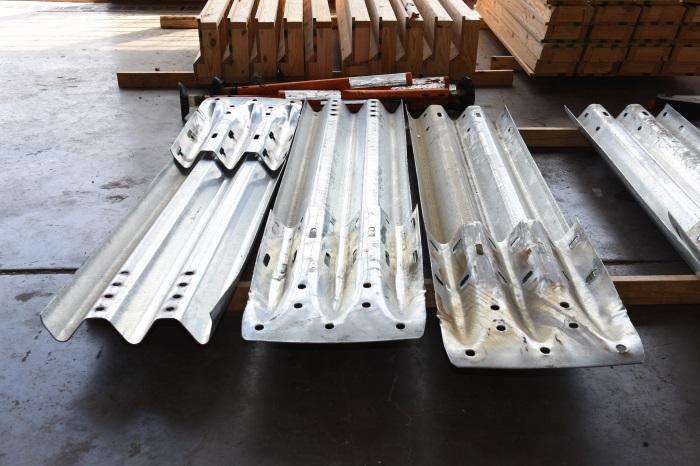
13 CHAPTER 1: INTRODUCTION 1.1 PROBLEM/BACKGROUND Terminal thrie end shoes are commonly used to connect nested thrie beam rails to parapets or other bridge rail structure to provide robust connectivity between an approach rail transition section and a rigid railing section. When connecting terminal end shoe to nested thrie beam transition rails, the thrie beam section profile results in shifting of the splice bolt connecting slots. This can result in slots misalignment through the three material layers, which makes installation and maintenance difficult. Multiple field adjustments are known to be used to fit the end shoe to the beam. Such methods include hammering of drift pins, or torching grinding away interfering metal, all of which may compromise the integrity of the sections being connected. The goal of this project is to evaluate existing end shoe design and develop design improvements that will reduce or eliminate the need for rail modifications in the field. Placement of a nested thrie beam and an end shoe connector in several configurations confirmed that the slots on the thrie beam rail sections and end shoe do not provide adequate alignment for permitting the bolting process without substantial physical modification of the rail. Figures 1.1 and 1.2 illustrate misalignment of the slots to a degree that makes it impossible to insert splice bolts without significant modifications. Figure 1.1. Thrie Beam and End Shoe. TR No


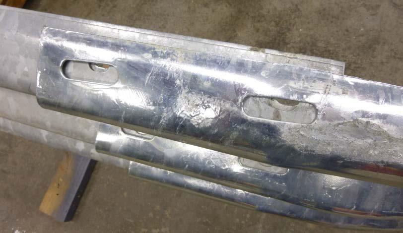
14 TR No Figure 1.2. Misalignment of Slots Due to Geometrical Shifting.
15 1.2 WORK PLAN This research effort followed the tasks listed below to substantially reduce alignment problems as the splice bolt slots and permit attachment of a nested thrie-beam to an end shoe connector without rail modifications: Study previous crash tests to acquire accelerations histories for existing thrie beam transition, Develop a finite element model of nested thrie transition with end shoe connector, Compare the acceleration from the simulation to the crash test acceleration history to establish validity of the simulation, Obtain force history at the end shoe connector to determine needed capacity, Suggest end shoe design modifications, and Test candidate solution to verify structural capacity to withstand the needed axial forces. 1.3 RECOMMENDED END SHOE DESIGN MODIFICATIONS The research team developed the following end shoe design concepts as potential solutions to reduce or eliminate interference associated with field installation of splice bolts: The addition of longitudinal slots along the length of the end shoe to provide greater flexibility to facilitate connection, A vertical or perpendicular orientation of the splice bolt slots compared to the current horizontal or longitudinal slots, and Larger diameter round holes instead of slots. These concepts are shown in Figures 1.3 through 1.5, respectively. Upon evaluation of the practicality of manufacturing and installation, the research team recommended the end shoe design concept with vertical slots as the candidate option with the most promising installation ease. TR No


16 Figure 1.3. Longitudinal Slots Along Bend Lines. Figure 1.4. Vertical Slots. Figure 1.5. Larger Diameter Holes Instead of Horizontal Slots. TR No
 Manual for Assessing Safety Hardware (MASH) testing guidelines at TL-3 impact")
17 1.4 REFERENCED TRANSITION TL-3 CRASH TESTS Two crash tests were studied to quantify axial forces experienced by an end shoe connector (1). These tests were recently conducted per American Association of State Highway and Transportation Officials (AASHTO) Manual for Assessing Safety Hardware (MASH) testing guidelines at TL-3 impact severity (2). In these tests, the transition system was flared 4 degrees from the roadway path, thereby increasing the effective impact angle to 29 degrees (25 degree impact angle + 4 degree flare). Hence, these tests can be considered a practical worst case for TL-3 transition impacts in terms of the axial load imparted on the transition rail section and end shoe connector. Specifically, the tests examined for the end shoe analysis were performed under Texas Department of Transportation (TxDOT) Project , Short Radius MASH TL-3 Guardrail Treatment. This project sought to develop and test a new MASH-compliant short radius guardrail system for treatment of bridge ends in close proximity to an intersecting roadway/driveway. In this project, two tests were performed following MASH Test 3-35 impact conditions. Test 3-35 involves a 5,000-lb pickup truck impacting the beginning of length of need at a nominal speed of 62 mph and a nominal angle of 25-degrees relative to the edge of the roadway. However, with the 4-degree system flare that existed, the effective impact angle was 29 degrees. In the first of two Test 3-35 impacts (Test No ), the vehicle impacted the thrie beam rail 15 ft upstream of the end shoe connector. The vehicle was redirected, but rolled upon exiting the system. Figure 1.6 shows the 5016-lb pickup that was used for the crash test. Figure 1.7 shows an overall view of the short radius guardrail used for these tests. Test Date: Project: TxDOT Project Vehicle: 2008 Dodge Ram 1500 Impact: 62.6 mph at 29 degree effective angle Accelerations * : Max longitudinal acceleration: 28.2 g Max lateral acceleration: 26.8 g * Class 60 filter Figure 1.6. Test No Vehicle Setup. TR No


18 Figure 1.7. Test Installation Setup. The second test, which also followed Test 3-35 impact conditions, is Test No After the failed test, an extra post was added near the upstream end of the thrie-beam transition and the test was repeated. This test passed all relevant MASH evaluation criteria. The actual impact point was 14 ft upstream of the end shoe connector. Figure 1.8 shows the 5014-lb pickup used for the crash test. Figure 1.9 shows the short radius guardrail installation used for the test. Test Date: Project : TxDOT Project Vehicle: 2008 Dodge Ram 1500 Impact: 64.5 mph at 25 degrees Accelerations * : Max longitudinal acceleration: 17.7 g Max lateral acceleration: 18.1 g * Class 60 filter Figure 1.8. Test No Vehicle Setup. Figure 1.9. Test No Installation Setup. TR No
19 Figure 1.10 presents the accelerations experienced by the vehicle during the two tests. Accelerations were filtered using an SAE class 60 filter. The maximum lateral acceleration was 18.1 g in test and 26.8 g in test as summarized in Table Accelerations Accelerations, G's Time, s Lateral Accelerations 15 Lateral Acceleration, G's Time, s Figure Test Nos and Lateral Acceleration Histories. TR No


20 Table 1.1. Maximum Lateral Acceleration from Crash Tests. Test No. Max Lateral, g FINITE ELEMENT MODEL A finite element model of the short radius thrie beam transition section was modified to aid in quantifying the longitudinal forces experienced by the end shoe connector under design crash test conditions. The transition model was derived from the detailed finite element model of the short radius guardrail system that featured a validated guardrail and truck model. The model included the nested thrie beam transition section connected to a rigid parapet via an end shoe connector. The overall short radius system model upstream of the nested thrie beam transition was cut and replaced with end boundary springs at the free end to represent the stiffness of the rest of the system. An impact simulation was performed with a 2270P pickup truck model striking the transition model under the actual test conditions. Figure 1.11 shows a series of sequential images from the simulation. Two variations of the model were developed for evaluation: one with the original end shoe from the short radius model, and one featuring a scanned model of the modified end shoe developed under this project. Figure Sequential Simulation Images. TR No
21 10 Vehicular Accelerations from Simulation 5 0 Acceleration, G's Lateral Time, s Figure Vehicular Acceleration from Short Transition Simulation. One of the advantages of using finite element modeling and simulation is that it allows for the examination of forces acting directly on the elements of the end shoe. This allows tracking of the force on these elements throughout the simulation. Cross-sections were defined through the end shoe part in the areas of interest, and forces were extracted at these crosssections. Forces were obtained in both the parallel (along the length of the end shoe connector) and perpendicular (normal to the end shoe connector surface) directions. The resulting forces were filtered using an SAE class 60 filter. One cross-section was taken directly through the end shoe, and an additional cross-section was taken through the nested thrie beam rails for comparison. Figure 1.13 displays the cross-section locations evaluated in the original end shoe, and Figure 1.14 presents the forces obtained from the simulation. The max forces on the nested thrie beam section are three kips higher than in the end shoe. In all simulated cases, the vehicle impacted the transition 9.5 ft upstream of the end shoe, which corresponds to the critical impact point recommended in MASH for the system. The maximum forces captured in the impact simulations are: Maximum Parallel Force = 40.0 kip Maximum Perpendicular Force = 7.84 kip at seconds TR No


22 Figure Cross Sections Analyzed for End Shoe and Nested Thrie Beam. TR No
23 Force, kip Forces in endshoe section Time, s 50 Forces in thrie beam section Force, kip Time, s Figure Cross-Section Forces Obtained for Unmodified End Shoe. TR No

24 1.6 CHANGE OF IMPACT LOCATIONS The research team investigated sensitivity of the longitudinal impact location on the maximum force applied to the end shoe. This involved moving the point of impact on the transition further downstream toward the end shoe connector as shown in the lower image of Figure Figure Two Impact Conditions Investigated Through Simulation. TR No
25 The simulated impact at the downstream impact location closer to the end shoe resulted in a higher axial forces in the nested thrie beams and end shoe connector. Figure 1.16 shows the time histories for these axial forces. The force-time history for the end shoe connector shows a second peak that is attributable to an edge contact of the vehicle with the end shoe. Based on these results, a design force was selected for the dynamic testing to demonstrate the structural adequacy of the modified end shoe connector design. 50 Longitudinal Section Forces in Thrie Beam and End Shoe: 2nd Impact Point 45 Force, kip Thrie Beam Force End Shoe Force Time, s Figure Longitudinal Section Forces Measured at the Nested Thrie Beam Section and the End Shoe Connector Section for Downstream Impact Location. TR No
26
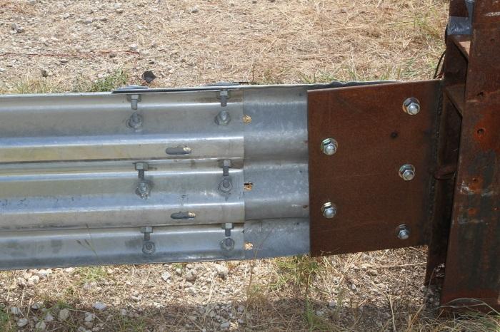
27 CHAPTER 2: TEST PLAN 2.1 TEST ARTICLE DESIGN AND INSTALLATION DETAILS The subject thrie beam end shoe was evaluated by dynamically loading a bolted connection between a 10-gauge end shoe and a section of 10-gauge thrie-beam (RTM-03b). Six tests were performed to assess the connection s performance when dynamically loaded/pulled in the axial direction by a 2062 lb pendulum bogie at a nominal speed of 20 mi/h. Figures 2.1 through 2.4 present details of the pendulum test setup. The tested end shoes were anchored to a W6 25 post, which was embedded into compacted soil comprised of AASHTO M crushed limestone road base (compacted to 95 percent of standard proctor density American Society for Testing Materials (ASTM) D698) such that its top was 36 inches above grade. Two /16-inch angle ground struts, each 64 inches long, connected the W6 25 at grade to a 14-inch square ¾-inch thick base plate, which was anchored to a concrete footing with six ¾-inch diameter embedded wedge anchors and bolts. The ground strut angles were welded to the inside of the W6 25 flanges and to the top of the base plate with ¼-inch fillet welds. The centerline of the post to the centerline of the base plate measured approximately 60 inches. After Test No P1, the W6 25 post was additionally reinforced. This reinforcement was comprised of two 3 3 ½-inch angle knee braces, each 68 inches long, welded to the outside flanges of the W6 25 at 31½ inches above grade, and to the base plate and ground struts. Each end shoe was bolted to an attachment plate that was welded to the W6 25 post. The ASTM A36 attachment plate measured 20 inches tall 16 inches wide ½ inch thick, overlapped one flange of the W6 25 by 2½ inches, and was fully welded to the W6 25 with a ⅜-inch fillet weld. The attachment plate contained five 1-inch diameter holes: two located 2 inches from the edge and each 3 13 /16-inches off of the horizontal centerline, two located 10 inches from the edge and each 7 9 /16 inches off of the horizontal centerline, and one located 10 inches from the edge and on the horizontal centerline. Each end shoe was bolted to the attachment plate with five ⅞-inch diameter, 2-inch long grade 5 hex bolts, with SAE hardened washers under the heads and hex nuts. Photographs of a typical test installation and setup are shown in Figure 2.4 TR No
28 TR No Figure 2.1. Test Installation Setup for Pendulum Testing.
29 TR No Figure 2.2. End Shoe Details.
30 TR No Figure 2.3. Thrie Beam Attachment Details.

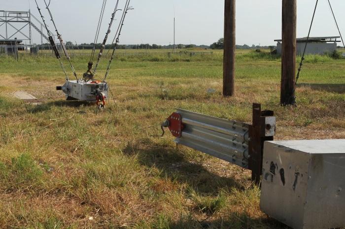
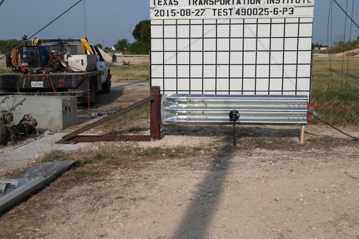
31 Figure 2.4. End Shoe/Thrie Beam Test Setup. TR No
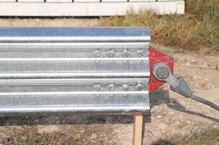
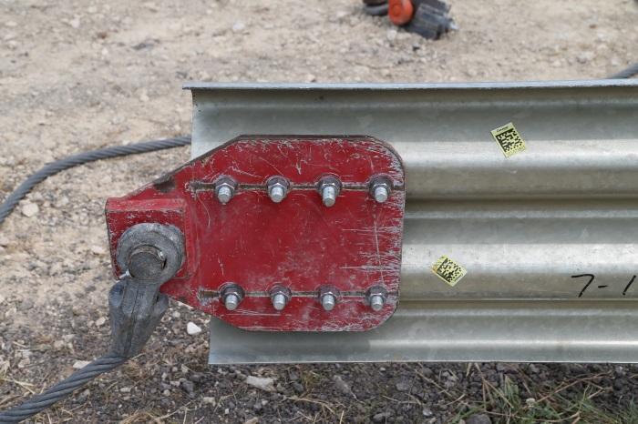
32 Each 6 ft-4½ inch long 10-guage, thrie beam guardrail section was cut from a standard 3- space, 10-guage thrie beam rail section (RTM-03b). One end of the thrie beam rail section contained a standard lap splice connection pattern consisting of twelve 1-inch wide 1⅛-inch long slots oriented horizontally. Each thrie beam section was attached to a terminal end shoe using twelve ⅝-inch diameter, 2-inch long guardrail splice bolts (FBB01), rectangular guardrail washers under the bolt heads, and recessed guardrail nuts on the back. These splice bolts were arranged in two sets of six bolts on 8½-inch longitudinal centers. The opposite end of the thrie beam had eight ¾-inch diameter holes that were used for attachment of the pendulum pull plate. The pendulum pull plate was connected to the thrie beam rail section using eight ⅝-inch diameter, 2-inch long ASTM A325 hex bolts, SAE hardened washers under the heads, and recessed guardrail nuts on the back. These bolts were arranged in four sets of two bolts on 3-inch longitudinal centers and 3 13 /16-inches off of the horizontal centerline. The pendulum pull plate was a 17¾-inch long 14-inch tall ½-inch thick steel plate. One end of the plate was tapered and had a 2⅛-inch diameter hole for a shackle pin. The other end contained four sets of 1-inch diameter holes on 3-inch longitudinal centers and 3⅞-inches off of the horizontal centerline of the plate. The pendulum pull plate and the thrie beam were positioned horizontal to grade with the shackle pin hole centered 16 inches above grade. See Figures 2.1 and 2.3. A 1-inch diameter wire rope with a clevis on each end connected the pendulum pull plate to either 1) an instrumented load cell that was attached to the pendulum, or 2) a custom tensile rod with diameter 1-inch long machined and polished frangible section (each rod was 10 inches long and cut from a single hardened 1½-inch diameter, 6 threads per inch, all-thread rod) that allowed a targeted 50,000 lb load on the test article. Refer to the test descriptions below for details of how each was used. Figures 2.1 through 2.3 present details of the test installation setup, and Figure 2.4 provides photographs of the installation. 2.2 TEST NO P1 END SHOE/THRIE BEAM CONNECTION DETAILS Test No P1 was a pull/jerk test in the longitudinal direction wherein the test article was pulled by the pendulum bogie at a height of 16 inches above grade. This test utilized TR No
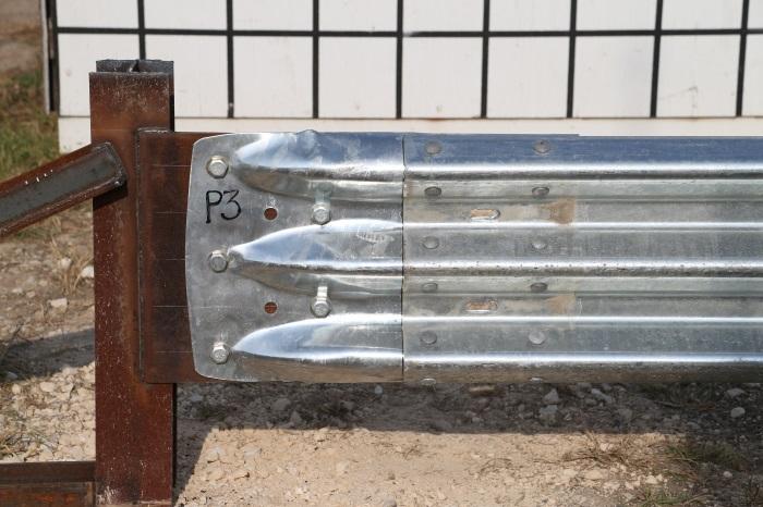
33 a standard thrie beam end shoe (RTE-01b) containing twelve 1-inch wide 3-inch long bolt slots oriented horizontally. For this test, the thrie beam was bolted to the back side of the end shoe. The height of the pendulum bogie upon release was 16.6 ft. An electronic load-cell was used to measure the applied force for Test No P1, meaning that a load-limiting tensile rod was not used. This resulted in the pendulum bogie-to-load cell connecting pin being bent. 2.3 TEST NO P2 END SHOE/THRIE BEAM CONNECTION DETAILS Test No P2 was a pull/jerk test in the longitudinal direction wherein the test article was pulled by the pendulum bogie at a height of 16 inches above grade. As noted above, knee braces were added to the anchor post prior to this test. This test utilized a standard thrie beam end shoe (TF-13 #RTE-01b) containing twelve 1-inch wide 3-inch long bolt slots oriented horizontally. For Test No P2, the thrie beam was bolted to the back side of the end shoe. The height of the pendulum bogie upon release was 9 ft. For Test No P2, neither the load-cell nor the tensile rod was employed. The cable clevis was directly pinned to the pendulum bogie. 2.4 TEST NO P3 END SHOE/THRIE BEAM CONNECTION DETAILS Test No P3 was a pull/jerk test in the longitudinal direction wherein the test article was yanked by the pendulum bogie at a height of 16 inches above grade. This test utilized a standard thrie beam end shoe (TF-13 #RTE-01b) containing twelve 1-inch wide 3-inch long bolt slots oriented horizontally. For Test No P3, the thrie beam was bolted to the front face of the end shoe. The height of the pendulum bogie upon release was 9 ft. For Test No P3, a load-limiting tensile rod was used in lieu of the load cell in Test No P1, and the rod severed under load as designed. 2.5 TEST NO P4 END SHOE/THRIE BEAM CONNECTION DETAILS Test No P4 was a pull/jerk test in the longitudinal direction wherein the test article was pulled by the pendulum bogie at a height of 16 inches above grade. This test utilized a modified thrie beam end shoe (similar to TF-13 #RTE-01b) that contained twelve 1-inch wide 2-inch long bolt slots oriented vertically. For Test No P4, the thrie-beam was bolted TR No
34 to the back side of the end shoe. The height of the pendulum bogie upon release was 9 ft. A loadlimiting tensile rod was used in lieu of the load cell, and the rod fractured under load as designed. 2.6 TEST NO P5 END SHOE/THRIE BEAM CONNECTION DETAILS Test No P5 was a pull/jerk test in the longitudinal direction wherein the test article was pulled by the pendulum bogie at a height of 16 inches above grade. This test utilized a modified thrie beam end shoe (similar to TF-13 #RTE-01b) that contained twelve 1-inch wide 2-inch long bolt slots oriented vertically. For Test No P5, the thrie beam was bolted to the front face of the end shoe. The height of the pendulum bogie upon release was 9 ft. A loadlimiting tensile rod was used in lieu of the load cell, and the rod fractured under load as designed. 2.7 TEST NO P6 END SHOE/THRIE BEAM CONNECTION DETAILS Test No P6 was a pull/jerk test in the longitudinal direction wherein the test article was pulled by the pendulum bogie at a height of 16 inches above grade. This test utilized a modified thrie beam end shoe (similar to TF-13 #RTE-01b) that contained twelve 1-inch wide 2-inch long bolt slots oriented vertically. For Test No P6, the thrie beam was bolted to the back side of the end shoe. The height of the pendulum bogie upon release was 9 ft. Again for Test No P6, a load-limiting tensile rod was used in lieu of the load cell, and the rod fractured under load as designed. TR No
35 CHAPTER 3: TEST CONDITIONS 3.1 TEST FACILITY The pendulum tests reported herein were performed at Texas A&M Transportation Institute (TTI) Proving Ground, an International Standards Organization (ISO) accredited laboratory with American Association for Laboratory Accreditation (A2LA) Mechanical Testing certificate The pendulum tests were performed according to TTI Proving Ground Quality System Procedure (QSP ), and according to National Cooperative Highway Research Program (NCHRP) Report 350 guidelines and standards. The TTI Proving Ground is a 2000-acre complex of research and training facilities located 10 miles northwest of the main campus of Texas A&M University. The site, formerly a United States Army Air Corps base, has large expanses of concrete runways and parking aprons that are well-suited for experimental research and testing in the areas of vehicle performance and handling, vehicle-roadway interaction, durability and efficacy of highway pavements, and safety evaluation of roadside safety hardware. 3.2 PENDULUM FACILITY The end shoe/thrie beam connections were tested at the TTI outdoor pendulum testing facility. The pendulum bogie, built according the specifications of the Federal Outdoor Impact Laboratory s (FOIL) pendulum, and the testing area are shown in the adjacent figure. The end shoes were installed such that the pendulum jerked/pulled on the thrie beam and end shoe at a prescribed speed dictated by the height of the pendulum. A brief description of the testing procedures follows. 3.3 DATA ACQUISITION SYSTEMS Electronic Instrumentation and Data Processing The pendulum was instrumented with two accelerometers mounted at the rear of the pendulum to measure longitudinal acceleration levels. The accelerometers were strain gage type with a linear millivolt output proportional to acceleration. TR No
36 The electronic signals from the accelerometers were amplified and transmitted to a base station by means of constant bandwidth FM/FM telemetry link for recording on magnetic tape and for display on a real-time strip chart. Calibration signals were recorded before and after the test and an accurate time reference signal was simultaneously recorded with the data. Pressure sensitive switches on the nose of the bogie were actuated by wooden dowel rods and initial contact to produce speed trap and event marks on the data record to establish the exact instant of contact with the installation, as well as impact velocity. The multiplex of data channels, transmitted on one radio frequency, is received and demultiplexed onto TEAC instrumentation data recorder. After the test, the data are played back from the TEAC recorder and digitized. A proprietary software program (WinDigit) converts the analog data from each transducer into engineering units using the R-cal and pre-zero values at 10,000 samples per second, per channel. WinDigit also provides Society of Automotive Engineers (SAE) J211 class 180 phaseless digital filtering and bogie impact velocity. The Test Risk Assessment Program (TRAP) uses the data from WinDigit to compute occupant/compartment impact velocities and the highest 10-ms average ridedown acceleration. WinDigit calculates change in bogie velocity at the end of a given impulse period. In addition, maximum average accelerations over 50 ms are computed Photographic Instrumentation and Data Processing A high-speed digital camera, positioned perpendicular to the path of the bogie and the test article, was used to record the test period. The film from this high-speed camera was analyzed on a computer to observe phenomena occurring during the test and to obtain timeevent, displacement, and angular data. A mini-dv camera and still cameras were used to document the pendulum nose and the end shoe/thrie beam connections before and after the test. TR No


 average acceleration was 18.8 G.")

37 CHAPTER 4: PENDULUM TESTING 4.1 TEST NO P1 Figure 4.1 shows the testing setup. The pendulum pulled on the thrie beam attached to the end shoe while traveling at 21.1 mi/h. Figure 4.2 shows the end shoe and thrie beam after Test No P1. The thrie beam was pulled 1¾ inches and the anchor post rotated slightly and was leaning 1 degree downstream. Maximum longitudinal second (10-ms) average acceleration was 13.0 G, and the maximum second (50-ms) average acceleration was 18.8 G. Peak force was 80.0 kips and maximum 10-ms average force was 51.7 kips. Figure 4.3 shows the force versus time trace for Test No P1. Figure 4.1. End Shoe before Test No P1. TR No


38 Figure 4.2. End Shoe after Test No P1. Figure 4.3. Force Trace for Test No P TEST NO P2 Figure 4.4 shows the test setup. The pendulum pulled on the thrie beam attached to the end shoe while traveling at 17.3 mi/h. The thrie beam was pulled 1⅝ inches and the concrete failed around the anchor post. Figure 4.5 shows the end shoe and thrie beam after Test No P2. Maximum longitudinal 10-ms average acceleration was 30.7 G, and the maximum 50- ms average acceleration was 18.0 G. Peak force was kips and maximum 10-ms average force was 63.5 kips. Figure 4.6 shows the force versus time trace for Test No P2. TR No


39 Figure 4.4. End Shoe before Test No P2. Figure 4.5. End Shoe after Test No P2. Figure 4.6. Force Trace for Test No P2. TR No


40 4.3 TEST NO P3 Figure 4.7 shows the testing setup. The pendulum pulled on the thrie beam attached to the end shoe while traveling at 19.9 mi/h. Figure 4.8 shows the end shoe and thrie beam after Test No P3. The thrie beam was pulled ½ inch and the in-line shear pin attached to the pendulum fractured and limited the applied force as designed. Longitudinal 10-ms average acceleration was 14.6G, and longitudinal 50-ms average acceleration was 2.1 G. Peak force was 58.6 kips and maximum 10-ms average force was 30.5 kips. Figure 4.9 shows the force versus time trace for Test No P3. Figure 4.7. End Shoe before Test No P3. Figure 4.8. End Shoe after Test No P3. TR No

41 Figure 4.9. Force Trace for Test No P TEST NO P4 A modified thrie beam end shoe with bolt slots oriented vertically and bolted to the back side of the end shoe was used for Test No P4. Figure 4.10 shows the testing setup. The pendulum pulled on the thrie beam attached to the end shoe while traveling at 19.9 mi/h. The thrie beam was pulled ⅜ inch at the top rib and ½ inch at the middle and bottom rib. Figure 4.11 shows the end shoe and thrie beam after Test No P4. The shear pin attached to the pendulum fractured as designed. Maximum longitudinal 10-ms average acceleration was 13.6 G, and maximum 50-ms average acceleration was 1.8 G. Peak force was 62.7 kips and maximum 10-ms average force was 28.2 kips. Figure 4.12 shows the force versus time trace for Test No P4. TR No


42 Figure End Shoe before Test No P4. Figure End Shoe after Test No P4. Figure Force Trace for Test No P4. TR No


43 4.5 TEST NO P5 A modified thrie beam end shoe with bolt slots oriented vertically and bolted to the front face of the end shoe was used for Test No P5. Figure 4.13 shows the testing setup. The pendulum pulled on the thrie beam attached to the end shoe while traveling at 20.0 mi/h. Figure 4.14 shows the end shoe and thrie beam after Test No P5. The thrie beam was pulled ⅜ inch at the top rib and 5 /16 inch at the middle and bottom rib. The shear pin attached to the pendulum fractured as designed. Maximum longitudinal 10-ms average acceleration was 13.6 G, and maximum 50-ms average acceleration was 2.5 G. Peak force was 47.0 kips and maximum 10-ms average force was 30.0 kips. Figure 4.15 shows the force versus time trace for Test No P5. Figure End Shoe before Test No P5. Figure End Shoe after Test No P5. TR No

44 Figure Force Trace for Test No P TEST NO P6 A modified thrie beam end shoe with bolt slots oriented vertically and bolted to the back side of the end shoe was used. Figure 4.16 shows the testing setup. The pendulum pulled on the thrie beam attached to the end shoe while traveling at 20.0 mi/h. Figure 4.17 shows the end shoe and thrie beam after Test No P6. The thrie beam was pulled ½ inch at the top rib and ⅜ inch at the middle and bottom rib. The shear pin attached to the pendulum fractured as designed. Maximum longitudinal 10-ms average acceleration was 17.9 G, and maximum 50-ms average acceleration was 4.9 G. Peak force was 79.6 kips and maximum 10-ms average force was 37.1 kips. Figure 4.18 shows the force versus time trace for Test No P6. TR No


45 Figure End Shoe before Test No P6. Figure End Shoe after Test No P6. Figure Force Trace for Test No P6. TR No
46
47 CHAPTER 5: SUMMARY AND CONCLUSIONS 5.1 SUMMARY OF RESULTS The research team performed finite element impact simulations to determine the maximum axial force carried by a thrie beam end connector in a transition crash test. The scenario that was modeled was a nested thrie beam transition connected to a concrete parapet using a thrie beam end connector. The nested thrie beam transition rail was flared away from the roadway, thus increasing the effective impact angle and representing a more severe lateral impact condition that would generate a higher axial load in the transition rail and thrie beam end connector. MASH Test 3-21 was simulated to obtain the impact loads in the thrie beam end connector. The MASH 2270P pickup truck impacted the thrie beam at a nominal speed of 62 mi/h and an effective impact angle of 29 degrees. The location of the impact was varied along the transition to obtain the highest axial force in the thrie beam end connector. The highest axial force obtained in the thrie beam connector was 45 kips. Six pendulum pull tests were conducted on a standard thrie beam end shoe connector and on a newly design end shoe connector with a vertical slots. These tests were meant to demonstrate equivalency of the new end shoe connector design in terms of withstanding axial design forces arising from vehicular impacts into transition sections. All of these tests were conducted at speeds that generated a pull force that met or exceeded the 45 kip design axial force obtained from the impact simulations. The new end shoe connector design performed well and showed no signs of damage or any performance issues in any of the tested cases. 5.2 CONCLUSIONS The new end shoe connector design with vertical slots performed satisfactorily when subjected to axial impact forces higher than the design impact loads associated with TL-3 impact conditions for a transition. This new end shoe design had a demonstrated capacity 186 percent greater than the transition design load determined through finite element impact simulation. The manufacturing process for this new end shoe connector should not be any different from the manufacturing process of the current end show connector design. The holes and slots are punched on a flat steel blank and then the punched steel blank sheet is cold formed into the end TR No
48 shoe connector shape. Hence, the modified end shoe design can be readily fabricated and should not significantly affect the manufacturing process or cost. TR No
49 CHAPTER 6. IMPLEMENTATION PLAN The modified end shoe connector with vertical slots that was tested under this project used circular holes in the flat portion of the thrie beam end shoe that was connected to the load frame. This was done to provide a tighter connection that would have less slippage and, therefore, produce higher loads in the terminal connector. In practice, some level of construction tolerance is preferred to facilitate field assembly. Since the vertical slots do not provide longitudinal construction tolerance, it is recommended that horizontal slots (rather than circular holes) be used in the flat portion of the terminal connector that connects the thrie beam end shoe to the bridge rail parapet. Use of the horizontal slots on the flat region of the connector will allow for field construction tolerance without changing the function or performance of the end shoe connector. Figure 6.1 shows details of the design that is recommended for implementation. It incorporates 2-inch vertical slots to improve attachment of the end shoe connector with nested thrie beam rail, and 2-in wide horizontal slots on the flat area of the end shoe connector to provide field construction tolerance. Use of this new end shoe connector should eliminate the need for field modification of the thrie beam rail while still maintaining field construction tolerance. The cost of the new end shoe connector should be comparable to the existing design. TR No
50 Figure 6.1. Recommended End Shoe Design. TR No
51 REFERENCES 1. Akram Y. Abu-Odeh, Katherine McCaskey, Roger P. Bligh, Wanda L. Menges, and Darrell L. Kuhn. Crash Test and MASH Tl-3 Evaluation of the TxDOT Short Radius Guardrail. Report No , Texas A&M Transportation Institute, College Station: The Texas A&M University System, AASHTO. Manual for Assessing Roadside Safety Hardware. 2009, American Association of State Highway and Transportation Officials: Washington, D.C. TR No
52
Advances in Simulating Corrugated Beam Barriers under Vehicular Impact
 13 th International LS-DYNA Users Conference Session: Automotive Advances in Simulating Corrugated Beam Barriers under Vehicular Impact Akram Abu-Odeh Texas A&M Transportation Institute Abstract W-beam
A MASH Compliant W-Beam Median Guardrail System
 0 0 0 0 0 A MASH Compliant W-Beam Median Guardrail System By A. Y. Abu-Odeh, R. P. Bligh, W. Odell, A. Meza, and W. L. Menges Submitted: July 0, 0 Word Count:, + ( figures + tables=,000) =, words Authors:
Manual for Assessing Safety Hardware
 American Association of State Highway and Transportation Officials Manual for Assessing Safety Hardware 2009 vii PREFACE Effective traffic barrier systems, end treatments, crash cushions, breakaway devices,
Evaluation of Barriers for Very High Speed Roadways
 TTI: 0-6071 Evaluation of Barriers for Very High Speed Roadways ISO 17025 Laboratory Testing Certificate # 2821.01 Crash testing performed at: TTI Proving Ground 3100 SH 47, Building 7091 Bryan, TX 77807
CRASH TEST AND EVALUATION OF 3-FT MOUNTING HEIGHT SIGN SUPPORT SYSTEM
 TTI: 9-1002-15 CRASH TEST AND EVALUATION OF 3-FT MOUNTING HEIGHT SIGN SUPPORT SYSTEM ISO 17025 Laboratory Testing Certificate # 2821.01 Crash testing performed at: TTI Proving Ground 3100 SH 47, Building
MASH Test 3-11 on the T131RC Bridge Rail
 TTI: 9-1002-12 MASH Test 3-11 on the T131RC Bridge Rail ISO 17025 Laboratory Testing Certificate # 2821.01 Crash testing performed at: TTI Proving Ground 3100 SH 47, Building 7091 Bryan, TX 77807 Test
ASTM F TEST M30 ON THE RSS-3000 DROP BEAM SYSTEM
 Proving Ground Test Report No.: 510602-RSS3 Test Report Date: January 2014 ASTM F2656-07 TEST M30 ON THE RSS-3000 DROP BEAM SYSTEM by Dean C. Alberson, Ph.D., P.E. Research Engineer Michael S. Brackin,
DEVELOPMENT OF A MASH TL-3 MEDIAN BARRIER GATE
 TTI: 9-1002 DEVELOPMENT OF A MASH TL-3 MEDIAN BARRIER GATE ISO 17025 Laboratory Testing Certificate # 2821.01 Crash testing performed at: TTI Proving Ground 3100 SH 47, Building 7091 Bryan, TX 77807 Research/Test
METAL BEAM GUARDFENCE TRANSITION AND END TREATMENT IDENTIFICATION GUIDE
 2016 TxDOT Design Division METAL BEAM GUARDFENCE TRANSITION AND END TREATMENT IDENTIFICATION GUIDE A guide to help TxDOT employees identify metal beam guardfence transitions and end treatments for the
NCHRP Report 350 Crash Testing and Evaluation of the S-Square Mailbox System
 TTI: 0-5210 NCHRP Report 350 Crash Testing and Evaluation of the S-Square Mailbox System ISO 17025 Laboratory Testing Certificate # 2821.01 Crash testing performed at: TTI Proving Ground 3100 SH 47, Building
MASH 2016 Implementation: What, When and Why
 MASH 2016 Implementation: What, When and Why Roger P. Bligh, Ph.D., P.E. Senior Research Engineer Texas A&M Transportation Institute June 7, 2016 2016 Traffic Safety Conference College Station, Texas Outline
CRASH TEST AND EVALUATION OF TEMPORARY WOOD SIGN SUPPORT SYSTEM FOR LARGE GUIDE SIGNS
 TTI: 9-1002-15 CRASH TEST AND EVALUATION OF TEMPORARY WOOD SIGN SUPPORT SYSTEM FOR LARGE GUIDE SIGNS ISO 17025 Laboratory Testing Certificate # 2821.01 Crash testing performed at: TTI Proving Ground 3100
MASH TEST 3-11 OF THE TxDOT T222 BRIDGE RAIL
 TTI: 9-1002-12 MASH TEST 3-11 OF THE TxDOT T222 BRIDGE RAIL ISO 17025 Laboratory Testing Certificate # 2821.01 Crash testing performed at: TTI Proving Ground 3100 SH 47, Building 7091 Bryan, TX 77807 Test
MASH TEST 3-37 OF THE TxDOT 31-INCH W-BEAM DOWNSTREAM ANCHOR TERMINAL
 TTI: 9-1002 MASH TEST 3-37 OF THE TxDOT 31-INCH W-BEAM DOWNSTREAM ANCHOR TERMINAL ISO 17025 Laboratory Testing Certificate # 2821.01 Crash testing performed at: TTI Proving Ground 3100 SH 47, Building
Form DOT F (8-72) Texas Transportation Institute The Texas A&M University System College Station, Texas
 Texas Transportation Institute The Texas A&M University System College Station, Texas") 1. Report No. FHWA/TX-02/4162-1 Technical Report Documentation Page 2. Government Accession No. 3. Recipient's Catalog No. 4. Title and Subtitle EVALUATION OF TEXAS GRID-SLOT PORTABLE CONCRETE BARRIER
1. Report No. FHWA/TX-02/4162-1 Technical Report Documentation Page 2. Government Accession No. 3. Recipient's Catalog No. 4. Title and Subtitle EVALUATION OF TEXAS GRID-SLOT PORTABLE CONCRETE BARRIER
Texas Transportation Institute The Texas A&M University System College Station, Texas
 1. Report No. FHWA/TX-05/9-8132-P7 4. Title and Subtitle TL-4 CRASH TESTING OF THE F411 BRIDGE RAIL 2. Government Accession No. 3. Recipient's Catalog No. 5. Report Date October 2004 Technical Report Documentation
TEXAS TRANSPORTATION INSTITUTE THE TEXAS A & M UNIVERSITY SYSTEM COLLEGE STATION, TEXAS 77843
 NCHRP REPORT 350 ASSESSMENT OF EXISTING ROADSIDE SAFETY HARDWARE by C. Eugene Buth, P.E. Senior Research Engineer Wanda L. Menges Associate Research Specialist and Sandra K. Schoeneman Research Associate
MASH TEST 3-11 OF THE TxDOT SINGLE SLOPE BRIDGE RAIL (TYPE SSTR) ON PAN-FORMED BRIDGE DECK
 ON PAN-FORMED BRIDGE DECK") TTI: 9-1002 MASH TEST 3-11 OF THE TxDOT SINGLE SLOPE BRIDGE RAIL (TYPE SSTR) ON PAN-FORMED BRIDGE DECK ISO 17025 Laboratory Testing Certificate # 2821.01 Crash testing performed at: TTI Proving Ground
TTI: 9-1002 MASH TEST 3-11 OF THE TxDOT SINGLE SLOPE BRIDGE RAIL (TYPE SSTR) ON PAN-FORMED BRIDGE DECK ISO 17025 Laboratory Testing Certificate # 2821.01 Crash testing performed at: TTI Proving Ground
MASH TEST 3-10 ON 31-INCH W-BEAM GUARDRAIL WITH STANDARD OFFSET BLOCKS
 TTI: 9-1002 MASH TEST 3-10 ON 31-INCH W-BEAM GUARDRAIL WITH STANDARD OFFSET BLOCKS ISO 17025 Laboratory Testing Certificate # 2821.01 Crash testing performed at: TTI Proving Ground 3100 SH 47, Building
MASH08 TEST 3-11 OF THE ROCKINGHAM PRECAST CONCRETE BARRIER
 Proving Ground Report No. 400001-RPC4 Report Date: July 2009 MASH08 TEST 3-11 OF THE ROCKINGHAM PRECAST CONCRETE BARRIER by C. Eugene Buth, P.E. Research Engineer William F. Williams, P.E. Assistant Research
1962: HRCS Circular 482 one-page document, specified vehicle mass, impact speed, and approach angle for crash tests.
 1 2 3 1962: HRCS Circular 482 one-page document, specified vehicle mass, impact speed, and approach angle for crash tests. 1973: NCHRP Report 153 16-page document, based on technical input from 70+ individuals
Performance Based Design for Bridge Piers Impacted by Heavy Trucks
 Performance Based Design for Bridge Piers Impacted by Heavy Trucks Anil K. Agrawal, Ph.D., P.E., Ran Cao and Xiaochen Xu The City College of New York, New York, NY Sherif El-Tawil, Ph.D. University of
Development of Turning Templates for Various Design Vehicles
 Transportation Kentucky Transportation Center Research Report University of Kentucky Year 1991 Development of Turning Templates for Various Design Vehicles Kenneth R. Agent Jerry G. Pigman University of
MASH TEST 3-21 ON TL-3 THRIE BEAM TRANSITION WITHOUT CURB
 TTI: 9-1002-12 MASH TEST 3-21 ON TL-3 THRIE BEAM TRANSITION WITHOUT CURB ISO 17025 Laboratory Testing Certificate # 2821.01 Crash testing performed at: TTI Proving Ground 3100 SH 47, Building 7091 Bryan,
Texas Transportation Institute The Texas A&M University System College Station, Texas
 1. Report No. FHWA/TX-07/0-5527-1 4. Title and Subtitle DEVELOPMENT OF A LOW-PROFILE TO F-SHAPE TRANSITION BARRIER SEGMENT 2. Government Accession No. 3. Recipient's Catalog No. Technical Report Documentation
AASHTO Manual for Assessing Safety Hardware, AASHTO/FHWA Joint Implementation Plan Standing Committee on Highways September 24, 2015
 AASHTO Manual for Assessing Safety Hardware, 2015 AASHTO/FHWA Joint Implementation Plan Standing Committee on Highways September 24, 2015 Full Scale MASH Crash Tests (NCHRP 22-14(02)) Conducted several
Technical Report Documentation Page 2. Government Accession No. 3. Recipient's Catalog No. 1. Report No. FHWA/TX-09/
 1. Report No. FHWA/TX-09/0-6071-1 4. Title and Subtitle ANALYSIS OF ROADSIDE SAFETY DEVICES FOR USE ON VERY HIGH-SPEED ROADWAYS Technical Report Documentation Page 2. Government Accession No. 3. Recipient's
I. 22. Price. Technical Report Documentation Page
 1. Report No. TX-00/1914-5 1 2. Government Accession No. 4. Title and Subtitle THE 1995 PERFORMANCE RESULTS FOR SLOPE PROTECTION PRODUCTS, HYDRAULIC MULCHES, AND FLEXIBLE CHANNEL LINERS Technical Report
The University of Texas at Arlington The University of Texas System Texas Transportation Institute The Texas A&M University System
 1. Report No. FHWA/TX-08/5-4385-01-1 4. Title and Subtitle PILOT IMPLEMENTATION OF BUMP DETECTION PROFILER Technical Report Documentation Page 2. Government Accession No. 3. Recipient's Catalog No. 5.
Heating Comparison of Radial and Bias-Ply Tires on a B-727 Aircraft
 'S Heating Comparison of Radial and Bias-Ply Tires on a B-727 Aircraft November 1997 DOT/FAA/AR-TN97/50 This document is available to the U.S. public through the National Technical Information Service
NCHRP Report 350 Test 4-12 of the Modified Thrie Beam Guardrail
 NCHRP Report 350 Test 4-12 of the Modified Thrie Beam Guardrail PUBLICATION NO. FHWA-RD-99-065 DECEMBER 1999 Research, Development, and Technology Turner-Fairbank Highway Research Center 6300 Georgetown
REPORT NO. TR-P NC SAFETY COMPLIANCE TESTING FOR FMVSS 223 REAR IMPACT GUARDS 2007 TRANSFREIGHT TECHNOLOGY NHTSA NO.
 REPORT NO. SAFETY COMPLIANCE TESTING FOR FMVSS 223 REAR IMPACT GUARDS 2007 TRANSFREIGHT TECHNOLOGY NHTSA NO. RIG 009 PREPARED BY: KARCO ENGINEERING, LLC. 9270 HOLLY ROAD ADELANTO, CALIFORNIA 92301 SEPTEMBER
KENTUCKY TRANSPORTATION CENTER
 Research Report KTC-08-10/UI56-07-1F KENTUCKY TRANSPORTATION CENTER EVALUATION OF 70 MPH SPEED LIMIT IN KENTUCKY OUR MISSION We provide services to the transportation community through research, technology
Technical Report Documentation Page Form DOT F (8-72) Reproduction of completed page authorized
 Reproduction of completed page authorized") 1. Report No. FHWA/TX-05/0-4162-3 4. Title and Subtitle 2. Government Accession No. 3. Recipient's Catalog No. DEVELOPMENT OF LOW-DEFLECTION PRECAST CONCRETE ARRIER 5. Report Date January 2005 Technical
1. Report No. FHWA/TX-05/0-4162-3 4. Title and Subtitle 2. Government Accession No. 3. Recipient's Catalog No. DEVELOPMENT OF LOW-DEFLECTION PRECAST CONCRETE ARRIER 5. Report Date January 2005 Technical
Evaluation and Design of ODOT s Type 5 Guardrail with Tubular Backup
 Evaluation and Design of ODOT s Type 5 Guardrail with Tubular Backup Draft Final Report Chuck A. Plaxico, Ph.D. James C. Kennedy, Jr., Ph.D. Charles R. Miele, P.E. for the Ohio Department of Transportation
EXTENDING TL-2 SHORT-RADIUS GUARDRAIL TO LARGER RADII
 Research Project Number TPF-5(193) Supplement 27 EXTENDING TL-2 SHORT-RADIUS GUARDRAIL TO LARGER RADII Submitted by Cody S. Stolle, Ph.D., E.I.T. Post-Doctoral Research Associate Robert W. Bielenberg,
Crash Testing Growth Common Roadside Hardware Systems Draft FHWA and AASHTO Requirements for Implementing MASH 2015
 64 th Annual Illinois Traffic Safety and Engineering Conference October 14, 2015 Crash Testing Growth Common Roadside Hardware Systems Draft FHWA and AASHTO Requirements for Implementing MASH 2015 1 https://www.youtube.com/watch?feature
Crash Performance of Strong-Post W-Beam Guardrail with Missing Blockouts Carolyn E. Hampton and Hampton C. Gabler
 Crash Performance of Strong-Post W-Beam Guardrail with Missing Blockouts Carolyn E. Hampton and Hampton C. Gabler Virginia Tech Center for Injury Biomechanics, Blacksburg VA 24061 Abstract Missing blockouts
SUMMARY CHANGES FOR NCHRP REPORT 350 GUIDELINES [NCHRP (02)] Keith A. Cota, Chairman Technical Committee on Roadside Safety June 14, 2007
![SUMMARY CHANGES FOR NCHRP REPORT 350 GUIDELINES [NCHRP (02)] Keith A. Cota, Chairman Technical Committee on Roadside Safety June 14, 2007](/thumbs/87/97351925.jpg "SUMMARY CHANGES FOR NCHRP REPORT 350 GUIDELINES [NCHRP (02)] Keith A. Cota, Chairman Technical Committee on Roadside Safety June 14, 2007") SUMMARY CHANGES FOR NCHRP REPORT 350 GUIDELINES [NCHRP 22-14 (02)] Keith A. Cota, Chairman Technical Committee on Roadside Safety June 14, 2007 BACKGROUND Circular 482 (1962) First full scale crash test
SUMMARY CHANGES FOR NCHRP REPORT 350 GUIDELINES [NCHRP 22-14 (02)] Keith A. Cota, Chairman Technical Committee on Roadside Safety June 14, 2007 BACKGROUND Circular 482 (1962) First full scale crash test
PR V2. Submitted by. Professor MIDWEST Vine Street (402) Submitted to
 Submitted to") FINAL REPORT PR4893118-V2 ZONE OF INTRUSION STUDY Submitted by John D. Reid, Ph.D. Professor Dean L.. Sicking, Ph.D., P.E. Professorr and MwRSF Director MIDWEST ROADSIDE SAFETY FACILITY University of Nebraska-Lincoln
FINAL REPORT PR4893118-V2 ZONE OF INTRUSION STUDY Submitted by John D. Reid, Ph.D. Professor Dean L.. Sicking, Ph.D., P.E. Professorr and MwRSF Director MIDWEST ROADSIDE SAFETY FACILITY University of Nebraska-Lincoln
FHWA/IN/JTRP-2000/23. Final Report. Sedat Gulen John Nagle John Weaver Victor Gallivan
 FHWA/IN/JTRP-2000/23 Final Report DETERMINATION OF PRACTICAL ESALS PER TRUCK VALUES ON INDIANA ROADS Sedat Gulen John Nagle John Weaver Victor Gallivan December 2000 Final Report FHWA/IN/JTRP-2000/23 DETERMINATION
Development of a Finite Element Model of a Motorcycle
 Development of a Finite Element Model of a Motorcycle N. Schulz, C. Silvestri Dobrovolny and S. Hurlebaus Texas A&M Transportation Institute Abstract Over the past years, extensive research efforts have
June 5, In Reply Refer To: HSSD/B-178. Mr. Kevin K. Groeneweg Mobile Barriers LLC Genesee Trail Road Golden, CO Dear Mr.
 June 5, 2008 1200 New Jersey Avenue, SE. Washington, DC 20590 In Reply Refer To: HSSD/B-178 Mr. Kevin K. Groeneweg Mobile Barriers LLC 24918 Genesee Trail Road Golden, CO 80401 Dear Mr. Groeneweg: This
June 27, In Reply Refer To: HSSD/B-176
 June 27, 2008 1200 New Jersey Avenue, SE. Washington, DC 20590 In Reply Refer To: HSSD/B-176 Mr. John Addy Hill & Smith Springvale Business and Industrial Park Bliston, Wolverhampton, West Midlands, UK,
SAFETY COMPLIANCE TESTING FOR FMVSS NO. 214S SIDE IMPACT PROTECTION (STATIC)
") REPORT NUMBER 214-GTL-09-002 SAFETY COMPLIANCE TESTING FOR S SIDE IMPACT PROTECTION (STATIC) MAZDA MOTOR CORPORATION 2009 MAZDA 3, PASSENGER CAR NHTSA NO. C95400 GENERAL TESTING LABORATORIES, INC. 1623
REPORT NUMBER 214-GTL-09-002 SAFETY COMPLIANCE TESTING FOR S SIDE IMPACT PROTECTION (STATIC) MAZDA MOTOR CORPORATION 2009 MAZDA 3, PASSENGER CAR NHTSA NO. C95400 GENERAL TESTING LABORATORIES, INC. 1623
July 17, In Reply Refer To: HSSD/B-176A
 July 17, 2008 1200 New Jersey Avenue, SE. Washington, DC 20590 In Reply Refer To: HSSD/B-176A Mr. John Addy Hill & Smith Springvale Business and Industrial Park Bliston, Wolverhampton, West Midlands, UK,
Virginia Department of Transportation
 TEST REPORT FOR: Virginia Department of Transportation SKT SP 350 50 (15.24 m) System PREPARED FOR: Virginia Department of Transportation 1401 E. Broad St. Richmond, VA 23219 TEST REPORT NUMBER: REPORT
Texas Transportation Institute The Texas A&M University System College Station, Texas
 1. Report No. FHWA/TX-04/9-8132-1 4. Title and Subtitle TESTING AND EVALUATION OF THE FLORIDA JERSEY SAFETY SHAPED BRIDGE RAIL 2. Government Accession No. 3. Recipient's Catalog No. 5. Report Date February
Implementation of AASHTO s Manual for Assessing Safety Hardware (MASH) 2016
 2016") Implementation of AASHTO s Manual for Assessing Safety Hardware (MASH) 2016 Update from the Technical Committee on Roadside Safety Keith Cota, New Hampshire DOT MASH 2016 Overview Background Ballot Results/Dates
Implementation of AASHTO s Manual for Assessing Safety Hardware (MASH) 2016 Update from the Technical Committee on Roadside Safety Keith Cota, New Hampshire DOT MASH 2016 Overview Background Ballot Results/Dates
Working Paper. Development and Validation of a Pick-Up Truck Suspension Finite Element Model for Use in Crash Simulation
 Working Paper NCAC 2003-W-003 October 2003 Development and Validation of a Pick-Up Truck Suspension Finite Element Model for Use in Crash Simulation Dhafer Marzougui Cing-Dao (Steve) Kan Matthias Zink
safedirection.com.au Ref: PM 017/02
 DISTRIBUTOR 0 Product Manual Ref: PM 017/02 Table of Contents 1.0 Introduction... 3 2.0 The... 3 3.0 How the Functions... 4 4.0 Crash Test Performance... 4 5.0 Characteristics of Terminals... 5 5.1 Gating
DEVELOPMENT OF A MASH TL-3 TRANSITION BETWEEN GUARDRAIL AND PORTABLE CONCRETE BARRIERS
 Duplication for publication or sale is strictly prohibited without prior written permission of the Transportation Research Board Paper No. 17-01712 DEVELOPMENT OF A MASH TL-3 TRANSITION BETWEEN GUARDRAIL
TRACC. Trinity Attenuating Crash Cushion
 TRACC Trinity Attenuating Crash Cushion CSP Pacific Business Unit of Fletcher Concrete & Infrastructure Limited 306 Neilson Street Onehunga, Auckland Phone: (09) 634 1239 or 0800 655 200 Fax: (09) 634
Sponsored by Roadside Safety Research Program Pooled Fund Study No. TPF-5(114)
") Proving Ground Test Report No. 405160-23-2 Test Report Date: February 2012 MASH TEST 3-11 OF THE W-BEAM GUARDRAIL ON LOW-FILL BOX CULVERT by William F. Williams, P.E. Associate Research Engineer and Wanda
Proving Ground Test Report No. 405160-23-2 Test Report Date: February 2012 MASH TEST 3-11 OF THE W-BEAM GUARDRAIL ON LOW-FILL BOX CULVERT by William F. Williams, P.E. Associate Research Engineer and Wanda
Evaluation of the Midwest Guardrail System stiffness transition with curb
 University of Nebraska - Lincoln DigitalCommons@University of Nebraska - Lincoln Civil Engineering Faculty Publications Civil Engineering 2016 Evaluation of the Midwest Guardrail System stiffness transition
EVALUATING THE RELEVANCY OF CURRENT CRASH TEST GUIDELINES FOR ROADSIDE SAFETY BARRIERS ON HIGH SPEED ROADS
 EVALUATING THE RELEVANCY OF CURRENT CRASH TEST GUIDELINES FOR ROADSIDE SAFETY BARRIERS ON HIGH SPEED ROADS CONNIE XAVIER DOMINIQUE LORD, PH.D. Zachry Department of Civil Engineering, Texas A&M University
CRASH TEST REPORT FOR PERIMETER BARRIERS AND GATES TESTED TO SD-STD-02.01, REVISION A, MARCH Anti-Ram Bollards
 CRASH TEST REPORT FOR PERIMETER BARRIERS AND GATES TESTED TO SD-STD-02.01, REVISION A, MARCH 2003 Anti-Ram Bollards Prepared for: RSA Protective Technologies, LLC 1573 Mimosa Court Upland, CA 91784 Test
Texas Transportation Institute The Texas A&M University System College Station, Texas
 2. Government Accession No. 3. Recipient's Catalog No. 1. Report No. FHWA/TX-03/0-4138-3 4. Title and Subtitle PERFORMANCE OF THE TXDOT T202 (MOD) BRIDGE RAIL REINFORCED WITH FIBER REINFORCED POLYMER BARS
DEVELOPMENT OF A TRANSITION BETWEEN FREE-STANDING AND REDUCED-DEFLECTION PORTABLE CONCRETE BARRIERS PHASE I
 Research Project Number TPF-5(193) Supplement #78 DEVELOPMENT OF A TRANSITION BETWEEN FREE-STANDING AND REDUCED-DEFLECTION PORTABLE CONCRETE BARRIERS PHASE I Submitted by Mojdeh Asadollahi Pajouh, Ph.D.
FAAC International, Inc.
 TEST REPORT FOR: FAAC International, Inc. J 355 HA M30 (K4) Bollard TESTED TO: ASTM F 2656-07 Standard Test Method for Vehicle Crash Testing of Perimeter Barriers Test M30 PREPARED FOR: FAAC International,
ROBUST PROJECT Norwegian Public Roads Administration / Force Technology Norway AS
 ROBUST PROJECT Norwegian Public Roads Administration / Force Technology Norway AS Evaluation of small car - RM_R1 - prepared by Politecnico di Milano Volume 1 of 1 January 2006 Doc. No.: ROBUST-5-002/TR-2004-0039
Product Specification. ABSORB 350 TM TL-2 Non-Redirective, Gating, Crash Cushion Applied to Quickchange Moveable Barrier
 TB 000612 Rev. 0 Page 1 of 9 Product Specification ABSORB 350 TM TL-2 Non-Redirective, Gating, Crash Cushion Applied to Quickchange Moveable Barrier I. General The ABSORB 350 TM TL-2 System is a Non-Redirective,
A Recommended Approach to Pipe Stress Analysis to Avoid Compressor Piping Integrity Risk
 A Recommended Approach to Pipe Stress Analysis to Avoid Compressor Piping Integrity Risk by: Kelly Eberle, P.Eng. Beta Machinery Analysis Calgary, AB Canada keberle@betamachinery.com keywords: reciprocating
Evaluation of the Midwest Guardrail System Stiffness Transition with Curb
 Duplication for publication or sale is strictly prohibited without prior written permission of the Transportation Research Board Paper No. -0 Evaluation of the Midwest Guardrail System Stiffness Transition
July 10, Refer to: HSA-10/CC-78A
 July 10, 2003 Refer to: HSA-10/CC-78A Barry D. Stephens, P.E. Senior Vice President of Engineering ENERGY ABSORPTION Systems, Inc. 3617 Cincinnati Avenue Rocklin, California 95765 Dear Mr. Stephens: Your
COMPARISON OF THE IMPACT PERFORMANCE OF THE G4(1W) AND G4(2W) GUARDRAIL SYSTEMS UNDER NCHRP REPORT 350 TEST 3-11 CONDITIONS
 AND G4(2W) GUARDRAIL SYSTEMS UNDER NCHRP REPORT 350 TEST 3-11 CONDITIONS") Paper No. 00-0525 COMPARISON OF THE IMPACT PERFORMANCE OF THE G4(1W) AND G4(2W) GUARDRAIL SYSTEMS UNDER NCHRP REPORT 350 TEST 3-11 CONDITIONS by Chuck A. Plaxico Associate Research Engineer Worcester Polytechnic
Paper No. 00-0525 COMPARISON OF THE IMPACT PERFORMANCE OF THE G4(1W) AND G4(2W) GUARDRAIL SYSTEMS UNDER NCHRP REPORT 350 TEST 3-11 CONDITIONS by Chuck A. Plaxico Associate Research Engineer Worcester Polytechnic
CRASH TEST REPORT FOR PERIMETER BARRIERS AND GATES TESTED TO SD-STD-02.01, REVISION A, MARCH Anti-Ram Bollards
 CRASH TEST REPORT FOR PERIMETER BARRIERS AND GATES TESTED TO SD-STD-02.01, REVISION A, MARCH 2003 Anti-Ram Bollards Prepared for: RSA Protective Technologies, LLC 1573 Mimosa Court Upland, CA 91784 Test
SAFETY COMPLIANCE TESTING FOR FMVSS 124 ACCELERATOR CONTROL SYSTEMS
 REPORT NUMBER 124-GTL-07-001 SAFETY COMPLIANCE TESTING FOR FMVSS 124 ACCELERATOR CONTROL SYSTEMS HYUNDAI MOTOR COMPANY 2007 HYUNDAI ELANTRA 4-DOOR PASSENGER CAR NHTSA NO. C70502 GENERAL TESTING LABORATORIES,
Assessing Options for Improving Roadside Barrier Crashworthiness
 13 th International LS-DYNA Users Conference Session: Simulation Assessing Options for Improving Roadside Barrier Crashworthiness D. Marzougui, C.D. Kan, and K.S. Opiela Center for Collision Safety and
GENERAL TESTING LABORATORIES, INC LEEDSTOWN ROAD COLONIAL BEACH, VIRGINIA 22443
 REPORT NUMBER 202a-GTL-10-004 SAFETY COMPLIANCE TESTING FOR S HEAD RESTRAINTS STATIC REQUIREMENTS VOLVO CAR CORPORATION 2010 VOLVO S40, PASSENGER CAR NHTSA NO. CA5900 GENERAL TESTING LABORATORIES, INC.
Simulating Rotary Draw Bending and Tube Hydroforming
 Abstract: Simulating Rotary Draw Bending and Tube Hydroforming Dilip K Mahanty, Narendran M. Balan Engineering Services Group, Tata Consultancy Services Tube hydroforming is currently an active area of
Evaluation of Retroreflectivity Measurement Techniques for Profiled and Rumble Stripe Pavement Markings
 PAPER #11-1293 Evaluation of Retroreflectivity Measurement Techniques for Profiled and Rumble Stripe Pavement Markings by Adam M. Pike, P.E. (Corresponding Author) Assistant Research Engineer Texas Transportation
SAFETY COMPLIANCE TESTING FOR FMVSS 124 ACCELERATOR CONTROL SYSTEMS
 REPORT NUMBER 124-GTL-10-004 SAFETY COMPLIANCE TESTING FOR FMVSS 124 ACCELERATOR CONTROL SYSTEMS FORD MOTOR CO. 2010 LINCOLN MKS, PASSENGER CAR NHTSA NO. CA0209 GENERAL TESTING LABORATORIES, INC. 1623
November 16, 1998 Refer to: HNG-14. Mr. David Allardyce Mechanical Engineer B&B Electromatic Main Street Norwood, Louisiana 70761
 November 16, 1998 Refer to: HNG-14 Mr. David Allardyce Mechanical Engineer B&B Electromatic 14113 Main Street Norwood, Louisiana 70761 Dear Mr. Allardyce: In your August 31 letter, you presented some preliminary
VULCAN BARRIER TL-3 GENERAL SPECIFICATIONS
 VULCAN BARRIER TL-3 GENERAL SPECIFICATIONS I. GENERAL A. The VULCAN BARRIER TL-3 (VULCAN TL-3) shall be a highly portable and crashworthy longitudinal barrier especially suited for use as a temporary barrier
Development and Validation of a Finite Element Model of an Energy-absorbing Guardrail End Terminal
 Development and Validation of a Finite Element Model of an Energy-absorbing Guardrail End Terminal Yunzhu Meng 1, Costin Untaroiu 1 1 Department of Biomedical Engineering and Virginia Tech, Blacksburg,
REPORT NUMBER: 111SB-MGA SAFETY COMPLIANCE TESTING FOR FMVSS NO. 111SB SCHOOL BUS REARVIEW MIRRORS
 REPORT NUMBER: 111SB-MGA-2009-001 SAFETY COMPLIANCE TESTING FOR FMVSS NO. 111SB SCHOOL BUS REARVIEW MIRRORS THOMAS BUILT BUSES 2009 THOMAS MINOTOUR SCHOOL BUS NHTSA NO.: C90901 PREPARED BY: MGA RESEARCH
SAFETY COMPLIANCE TESTING FOR FMVSS NO. 104 WINDSHIELD WIPING AND WASHING SYSTEMS
 REPORT NUMBER 104-GTL-07-003 SAFETY COMPLIANCE TESTING FOR FMVSS NO. 104 WINDSHIELD WIPING AND WASHING SYSTEMS HONDA MOTOR CO. 2007 HONDA FIT, PASSENGER CAR NHTSA NO. C75300 GENERAL TESTING LABORATORIES,
SAFETY COMPLIANCE TESTING FOR FMVSS 124 ACCELERATOR CONTROL SYSTEMS
 REPORT NUMBER 124-GTL-07-003 SAFETY COMPLIANCE TESTING FOR FMVSS 124 ACCELERATOR CONTROL SYSTEMS NISSAN MOTOR CO., LTD. 2007 NISSAN VERSA, 4-DOOR PASSENGER CAR NHTSA NO. C75201 GENERAL TESTING LABORATORIES,
Evaluating The Relevancy Of Current Crash Test Guidelines For Roadside Safety Barriers On High Speed Roads
 Evaluating The Relevancy Of Current Crash Test Guidelines For Roadside Safety Barriers On High Speed Roads Connie Xavier Dominique Lord Chiara Dobrovolny Roger Bligh TRB 1 st International Roadside Safety
FINAL REPORT FOR THE C-130 RAMP TEST #3 OF A HYDREMA MINE CLEARING VEHICLE
 AFRL-RX-TY-TP-2008-4543 FINAL REPORT FOR THE C-130 RAMP TEST #3 OF A HYDREMA MINE CLEARING VEHICLE Prepared by: William R. Meldrum Mechanical Engineer Physical Simulation Team AMSRD-TAR-D U.S. Army Tank-Automotive
SAFETY COMPLIANCE TESTING FOR FMVSS NO. 104 WINDSHIELD WIPING AND WASHING SYSTEMS
 REPORT NUMBER 104-GTL-07-002 SAFETY COMPLIANCE TESTING FOR FMVSS NO. 104 WINDSHIELD WIPING AND WASHING SYSTEMS NISSAN MOTOR CO., LTD. 2007 NISSAN VERSA, PASSENGER CAR NHTSA NO. C75201 GENERAL TESTING LABORATORIES,
Control of Pavement Smoothness in Kansas
 Report No. FHWA-KS-8-5 Final REPORT Control of Pavement Smoothness in Kansas William H. Parcells, Jr., P.E. Kansas Department of Transportation Topeka, Kansas May 29 KANSAS DEPARTMENT OF TRANSPORTATION
s MEDIAN BARRIERS FOR TEXAS HIGHWAYS
 s MEDIAN BARRIERS FOR TEXAS HIGHWAYS SUMMARY REPORT of Research Report Number 146-4 Study 2-8-68-146 Cooperative Research Program of the Texas Transportation Institute and the Texas Highway Department
VULCAN BARRIER TL-3 GENERAL SPECIFICATIONS
 VULCAN BARRIER TL-3 GENERAL SPECIFICATIONS I. GENERAL A. The VULCAN BARRIER TL-3 (VULCAN TL-3) shall be a highly portable and crashworthy longitudinal barrier especially suited for use as a temporary barrier
Linear Shaft Motors in Parallel Applications
 Linear Shaft Motors in Parallel Applications Nippon Pulse s Linear Shaft Motor (LSM) has been successfully used in parallel motor applications. Parallel applications are ones in which there are two or
REMOTE MINE AREA CLEARANCE EQUIPMENT (MACE) C-130 LOAD CELL TEST DATA
 C-130 LOAD CELL TEST DATA") AFRL-ML-TY-TR-2007-4543 REMOTE MINE AREA CLEARANCE EQUIPMENT (MACE) C-130 LOAD CELL TEST DATA Prepared by William R. Meldrum Mechanical Engineer Physical Simulation Team AMSRD-TAR-D U.S. Army Tank-Automotive
AFRL-ML-TY-TR-2007-4543 REMOTE MINE AREA CLEARANCE EQUIPMENT (MACE) C-130 LOAD CELL TEST DATA Prepared by William R. Meldrum Mechanical Engineer Physical Simulation Team AMSRD-TAR-D U.S. Army Tank-Automotive
The Deployable Gage Restraint Measurement System - Description and Operational Performance
 The Deployable Gage Restraint Measurement System - Description and Operational Performance GARY A. MARTIN ENSCO, INC 5400 PORT ROYAL ROAD SPRINGFIELD, VA 22151 703-321-4513 703-321-7619 (FAX) JEFFREY A.
*Friedman Research Corporation, 1508-B Ferguson Lane, Austin, TX ** Center for Injury Research, Santa Barbara, CA, 93109
 Analysis of factors affecting ambulance compartment integrity test results and their relationship to real-world impact conditions. G Mattos*, K. Friedman*, J Paver**, J Hutchinson*, K Bui* & A Jafri* *Friedman
DISTRIBUTION: Electronic Recipients List TRANSMITTAL LETTER NO. (15-01) MINNESOTA DEPARTMENT OF TRANSPORTATION. MANUAL: Road Design English Manual
 MINNESOTA DEPARTMENT OF TRANSPORTATION. MANUAL: Road Design English Manual") DISTRIBUTION: Electronic Recipients List MINNESOTA DEPARTMENT OF TRANSPORTATION DEVELOPED BY: Design Standards Unit ISSUED BY: Office of Project Management and Technical Support TRANSMITTAL LETTER NO.
DISTRIBUTION: Electronic Recipients List MINNESOTA DEPARTMENT OF TRANSPORTATION DEVELOPED BY: Design Standards Unit ISSUED BY: Office of Project Management and Technical Support TRANSMITTAL LETTER NO.
SAFETY COMPLIANCE TESTING FOR FMVSS NO. 103 WINDSHIELD DEFROSTING AND DEFOGGING SYSTEMS
 REPORT NUMBER 103-GTL-06-002 SAFETY COMPLIANCE TESTING FOR FMVSS NO. 103 WINDSHIELD DEFROSTING AND DEFOGGING SYSTEMS FORD MOTOR CO. 2006 FORD MUSTANG, PASSENGER CAR NHTSA NO. C60203 GENERAL TESTING LABORATORIES,
CHAPTER 9: VEHICULAR ACCESS CONTROL Introduction and Goals Administration Standards
 9.00 Introduction and Goals 9.01 Administration 9.02 Standards 9.1 9.00 INTRODUCTION AND GOALS City streets serve two purposes that are often in conflict moving traffic and accessing property. The higher
SAFETY COMPLIANCE TESTING FOR FMVSS NO. 225 CHILD RESTRAINT ANCHORAGE SYSTEMS LOWER AND TETHER ANCHORAGES
 REPORT NUMBER 225-GTL-06-006 SAFETY COMPLIANCE TESTING FOR FMVSS NO. 225 CHILD RESTRAINT ANCHORAGE SYSTEMS LOWER AND TETHER ANCHORAGES GENERAL MOTORS OF CANADA, LTD. 2005 BUICK LACROSSE, PASSENGER CAR
CFIRE December 2009
 i BRIDGE ANALYSIS AND EVALUATION OF EFFECTS UNDER OVERLOAD VEHICLES (PHASE 1) CFIRE 02-03 December 2009 National Center for Freight & Infrastructure Research & Education College of Engineering Department
SFI SPECIFICATION 35.2 EFFECTIVE: DECEMBER 29, 2014 *
 SFI SPECIFICATION 35.2 EFFECTIVE: DECEMBER 29, 2014 * PRODUCT: Heavy Duty Stock Car Steel Wheels 1.0 GENERAL INFORMATION 1.1 This SFI Specification establishes uniform test procedures and minimum standards
Design Aids For Structural Welded Wire Reinforcement (Metric Units for WWR/Rebar Comparison Tables)
") TF 209-R-08 Metric Design Aids For Structural Welded Wire Reinforcement (Metric Units for WWR/Rebar Comparison Tables) INTRODUCTION This Tech Fact* provides basic information on coldworked wire and welded
TF 209-R-08 Metric Design Aids For Structural Welded Wire Reinforcement (Metric Units for WWR/Rebar Comparison Tables) INTRODUCTION This Tech Fact* provides basic information on coldworked wire and welded
TEXAS TRANSPORTATION INSTITUTE THE TEXAS A & M UNIVERSITY SYSTEM COLLEGE STATION, TEXAS 77843
 NCHRP REPORT 350 TEST 3-11 OF THE NEW YORK DOT PORTABLE CONCRETE BARRIER WITH I-BEAM CONNECTION (RETEST) by Roger P. Bligh, P.E. Assistant Research Engineer Wanda L. Menges Associate Research Specialist
REPORT NUMBER: 301-CAL SAFETY COMPLIANCE TESTING FOR FMVSS 301 FUEL SYSTEM INTEGRITY HONDA MOTOR COMPANY 2007 HONDA ACCORD 4-DOOR SEDAN
 REPORT NUMBER: 301-CAL-07-05 SAFETY COMPLIANCE TESTING FOR FMVSS 301 FUEL SYSTEM INTEGRITY HONDA MOTOR COMPANY 2007 HONDA ACCORD 4-DOOR SEDAN NHTSA NUMBER: C75304 CALSPAN TEST NUMBER: 8832-F301-05 CALSPAN
Development of Combination Pedestrian-Traffic Bridge Railings
 TRANSPORTATION RESEARCH RECORD 1468 41 Development of Combination Pedestrian-Traffic Bridge Railings D. LANCE BULLARD, JR., WANDA L. MENGES, AND C. EUGENE BUTH Two bridge railing designs have been developed
Determination of Spring Modulus for Several Types of Elastomeric Materials (O-rings) and Establishment of an Open Database For Seals*
 and Establishment of an Open Database For Seals*") Determination of Spring Modulus for Several Types of Elastomeric Materials (O-rings) and Establishment of an Open Database For Seals* W. M. McMurtry and G. F. Hohnstreiter Sandia National Laboratories,
Determination of Spring Modulus for Several Types of Elastomeric Materials (O-rings) and Establishment of an Open Database For Seals* W. M. McMurtry and G. F. Hohnstreiter Sandia National Laboratories,