safedirection.com.au Ref: PM 017/02
|
|
|
- Madlyn Daniels
- 5 years ago
- Views:
Transcription


1 DISTRIBUTOR 0 Product Manual Ref: PM 017/02
2 Table of Contents 1.0 Introduction The How the Functions Crash Test Performance Characteristics of Terminals Gating Classification The Point-of-Need Trailing End Protection Set-out Site Grading Requirements Advance Grading Adjacent Grading Run-Out Grading Kerbs Placement in Concrete Other Obstructions & Hazards Use of an Offset Placement on Curves Length Between Terminals Summary Designers Checklist
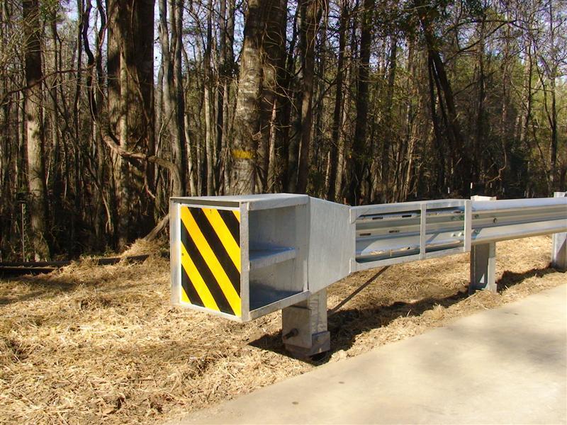
3 1.0 Introduction Roads safety barrier systems are designed to shield vehicles from striking a hazard. Steel guardrail systems are the world s most widely specified safety barrier systems and have significantly contributed to improving the safety of our regions roads. The strength of a steel guardrail system is primarily developed through a combination of the flexural resistance of the rail and the bending resistance of the supporting posts. In addition, the use of end terminals is an important characteristic in the function of a steel guardrail system. Terminals are the specially designed end pieces located at the leading and trailing end of the system. End terminals are designed to anchor the steel guardrail system and introduce the necessary tensile and flexural strength required for safe vehicle containment and re-direction throughout the length-of-need section. Some guardrail end terminals also provide the additional feature of reducing the severity of an impact near or at the end of the system. 2.0 The The guardrail end terminal is an energyabsorbing, tangent end terminal, designed to minimise the severity of impacts occurring at the end of the safety barrier system. Designed for attachment directly to w-beam guardrail, the is one of the world s leading end treatment solutions and is fully compliant to the requirements of NCHRP Report 350. The represents the latest configuration for the SKT terminal that was first introduced in Since that time the SKT has evolved to suit the challenges facing current designers and facilitate rapid installation and repair. The preserves many components used in the original SKT design including the impact head, slotted anchor rail concept and cable anchor bracket. The tangential design feature allows the to be installed parallel to the roadway reducing the requirement for earthworks and site grading associated with traditional parabolic-flared terminal designs. The is available in two configurations. The compact 7.62m TL2 terminal is an economical solution where the posted speed is less than or equal to 70km/h. The standard 15.24m TL3 terminal is acceptable for all posted speeds greater than 70km/h. 3
4 3.0 How the Functions The comprises several unique components integral to the performance of the terminal. These include; Slotted anchor rail; Impact head; Bolted hinged posts; Steel line posts; and Anchor bracket and cable assembly. During head-on impacts, the impact head slides over the w-beam guardrail. The w-beam is sequentially kinked as it moves through the head and exits away from the traffic face. The kinking action of the rail absorbs the kinetic energy of the impacting vehicle bringing the vehicle to a controlled stop. As the impact head slides over the w-beam guardrail, the bolted hinged posts at post locations 1 and 2 yield at ground level. The yielding action of the hinged posts contributes to a soft impact for vehicle occupants. The use of steel line posts at post locations 3 and beyond provides the with the necessary lateral support required for safe vehicle containment and re-direction through the length-ofneed section. 4.0 Crash Test Performance The has been crash tested and assessed in accordance with Test Level 3 (TL3) of the National Cooperative Highway Research Program (NCHRP) Report 350. NCHRP Report 350 is the nominated crash test procedure of AS/NZS 3845: Road Safety Barrier Systems and evaluates the structural adequacy of the terminal, vehicle occupant risk and post impact vehicle behaviour. Crash testing of the in accordance with NCHRP Report 350 TL3 was undertaken with an 820kg small car and a 2,000kg pick-up truck travelling at 100km/h. At the nose of the terminal, these impacts are performed end-on or at angles up to 15. Along the length-of-need, impacts are performed at 20. The is also available in a NCHRP Report 350 TL2 configuration. TL2 evaluates vehicle impacts occurring at 70km/h. The only difference between the TL3 and TL2 configuration of the is the length of the terminal. The TL2 configuration of the measures 7.62m compared to the TL3 configuration length of 15.24m. The hardware arrangement through the first 7.62m remains the same for both TL3 and TL2 terminals. The upper speed limit used for the evaluation of all guardrail end terminals in accordance with NCHRP Report 350 TL3 is 100km/h. Whilst there are roads within Australia with posted speeds greater than 100km/h the is acceptable for these high speed locations. A crash test performed at 100km/h is still considered representative of worst case run-off-road crashes. Extensive evaluation of real-life crash impacts has concluded that, regardless of posted speeds, most impacts with fixed objects occurs at somewhat reduced speeds, likely due to pre-crash application of brakes. 4

5 5.0 Characteristics of Terminals 5.1 Gating Classification Although the terms gating and non-gating have traditionally been used to categorise end terminal behaviour, these definitions can be misleading when applied to w-beam guardrail end terminals. The AS/NZS 3845 definitions of gating and nongating are as follows; Gating: terminals that are designed to break away, pivot or hinge, and that allow a vehicle to pass through when impacted at an angle to the end, or at a point upstream of the beginning length-of-need of the safety barrier system. Non-Gating: terminals that are designed to redirect and absorb part of the energy of an impacting vehicle at any point along the terminal without allowing it to pass behind the safety barrier system. All w-beam guardrail end terminals are gating terminals. When struck at or near the nose at an angle of 15 or greater, w-beam guardrail terminals will yield, allowing a vehicle to continue into the area immediately behind and beyond the terminal. However, a significant performance benefit of the is its ability to dissipate kinetic energy during a head-on impact occurring at the nose. This energyabsorbing feature brings the errant vehicle to a controlled stop over a relatively short distance, even at high impact speeds. The energy-absorbing feature of the contrasts with traditional, parabolic flared terminals such as the MELT and BCTA (used in Victoria). These traditional terminals are classified as non-energy absorbing and will allow an un-braked vehicle to travel a significant distance behind the barrier system when struck head-on at high speeds. 5
6 5.2 The Point-of-Need Since all w-beam guardrail end terminals fall into the gating category, it is important that the terminal point-of-need is identified. This is the location along the terminal that has demonstrated complete containment and re-direction when subjected to a 2,000kg pick-up truck impacting at 20. When assessed for TL3 conditions, the speed of the impact is performed at 100km/h. The point-of-need is post location 3, a distance of 3.81m downstream from the start of the terminal. In order to adequately shield a roadside hazard, the beginning length-of-need is required to be calculated for that site. At a minimum, the should be installed so that the terminal point-ofneed (post 3) aligns with the site beginning-lengthof-need. Figure 1 provides an example. The point-of-need location may vary between terminal types. However, provided the terminal point-of-need and the site beginning-length-of-need are horizontally aligned, the road safety barrier system will provide the same re-directive capabilities, regardless of the terminal selected. Terminal Point-of-Need Hazard Edge of Shoulder Direction of Travel a = Angle of Departure Figure 1: Positioning of Terminal Point-of-Need to Adequately Shield a Roadside Hazard 6
7 5.3 Trailing End Protection The is typically installed on the leading end of a guardrail barrier. However, in some instances it is necessary to install a crashworthy terminal on the trailing end. This occurs when the trailing end of a guardrail barrier is located within the clear zone of approaching traffic. The clear zone is the horizontal width of space available for the safe use of an errant vehicle. This distance is dependent upon the posted speed and road geometry. Guidelines for determining the clear zone width are contained within state road authority publications. Please note that in some Australian jurisdictions a crash worthy terminal is required on both the leading and trailing end of a guardrail barrier when installed on an undivided roadway. This is regardless of whether the trailing end is located outside the clear zone of approaching traffic. Please consult with state road authority publications for guidelines. Clear Zone Width for Vehicle 1 Required on Approach and Trailing End when within Clear Zone of Vehicles 1 & 2 1 Travelled Path Clear Zone Width for Vehicle 2 Travelled Path 2 Clear Zone Width for Vehicle 1 Clear Zone Width for Vehicle 2 Figure 2: Assessment of Trailing End Protection 7
8 6.0 Set-out Under crash test conditions, the surfaces immediately in front of and behind terminals are reasonably flat and unobstructed. In the field, conditions vary from site to site and obstructions such as kerbs, services and embankments are encountered. 6.1 Site Grading Requirements Grading around the area of a guardrail end terminal is an important consideration regardless of the specific terminal selected. The site grading should be considered from three perspectives; advance grading, adjacent grading and run-out grading Advance Grading It is recommended that the area in advance of a terminal be limited to a grading of 10H:1V to ensure that the vehicle s suspension is neither extended nor compressed at the moment of impact. An advantage of the is its tangential construction which may reduce the requirement for earthworks normally associated with the use of a traditional parabolic flared terminal such as the MELT or BCTA Adjacent Grading Adjacent grading refers to the surface on which the terminal is installed and the area immediately behind. It is recommended that this area be relatively flat (10H:1V) so that the terrain does not contribute to vehicle behaviour. Where re-direction is expected (beyond the point-of-need), the terminal posts should have 600mm of fill material behind them, providing sufficient lateral support Run-Out Grading Since all w-beam guardrail end terminals are gating, consideration must be given to the area parallel to and behind the safety barrier system. When struck at or near the nose at an angle of 15 or greater, w- beam guardrail end terminals will yield, allowing a vehicle to continue into the area immediately behind and beyond the terminal. AS/NZS 3845 Road safety Barrier Systems nominates an area measuring 22.5m long x 6.0m wide measured from the nose of the terminal to be reasonably traversable and free from fixed object hazards. This may be difficult to address, particularly on existing roadways. This is recognised by AS/NZS 3845 which also states that if a clear run-out area is not possible, this area should at least be similar in character to adjacent unshielded roadside areas. Generally a risk evaluation would conclude that an end terminal installed without the required run-out area could be considered a lower risk than leaving a roadside hazard completely unshielded. When the desirable run-out area is not available or when there is a high likelihood of a head-on impact with the terminal, the use of an energy-absorbing terminal such as the should be the preferred option over non-energy absorbing terminals such as the MELT and BCTA. The ability of the to dissipate energy during head-on impacts and bring an errant vehicle travelling at high-speed to a controlled stop over a short distance reduces the opportunity for an errant vehicle to pass behind the system. For near head-on impacts with the front-right of a vehicle, grading of 10H:1V should extend 1500mm behind the nose of the terminal, minimising the potential for vehicle roll as the terminal is engaged. 8
9 Variable Taper 1500mm Edge of Batter Grading of 10H:1V 600mm Edge of Shoulder Direction of Travel Figure 3: Preferred Grading Arrangement Variable Taper 3000mm Edge of Batter Grading of 10H:1V 600mm Edge of Shoulder Direction of Travel Figure 4: Alternate Grading Arrangement 9
10 6.2 Kerbs Placing kerbs in front of w-beam guardrail terminals on high-speed roads is not recommended. As an alternative, a shallow gutter in front of the terminal or subsurface grated drainage should be considered. On lower speed roads that often require a kerb, it is recommended that the location of the kerb be as close as practicable to the face of rail minimising the potential for vehicle launching. If the posted speed is 80km/h the kerb height should be limited to 100mm. 6.3 Placement in Concrete The line posts of the provide lateral resistance during side-on impacts and are designed to absorb some crash energy through post rotation in the surrounding material prior to fully yielding. There may be instances when designers prefer the area beneath the safety barrier system to be paved. Whilst a paved surface has aesthetic appeal, it is important that it does not have an adverse effect on the functionality of the terminal. When installed in a paved area, it is recommended that a leave-out area in the pavement be provided that will allow at least 180mm of post deflection at ground line. This leave-out area can be filled with a low-strength concrete mix. 6.4 Other Obstructions & Hazards During head-on impacts, the impact head slides over the w-beam guardrail. It is important that there are no obstructions located or positioned below the impact head, such as vegetation, that may hinder the travel of the impact head. An advantage of the is the shape of the impact head which provides increased clearance below the impact head minimising the potential for contacting ground level obstructions. Since the functions by sequentially kinking the rail away from the traffic face, a risk assessment is recommended if pedestrians and/or cyclists will be accessing the area behind the terminal. Leave-Out Behind the Post using Low- Strength Concrete Standard Strength Concrete Leave-Out may be Square or Round Plan View Figure 5: Recommended Post Set-Out for Placement in a Paved Area 10
11 6.5 Use of an Offset The is classified as a tangential end terminal and is installed parallel to the roadway. However, the may be installed on a 25:1 straight flare away from the roadway. This will achieve a 600mm offset measured from the face of rail over the length of the TL3 configuration (15.24m). Whilst providing a straight flare is not mandatory, the use of a straight flare positions the impact head further away from the edge of the travelled way and reduces the potential for nuisance impacts. 6.6 Placement on Curves When the is installed at the end of a guardrail system following a curved alignment, the must be installed along a straight alignment over the length of the terminal. To prevent encroachment onto the travelled way, the terminal may be installed on a tapered offset as described in Section Length Between Terminals The recommended minimum length of a w-beam guardrail barrier is generally 30m (includes the length of the terminals), although this may vary depending upon the design speed. There is no limitation on maximum length of a w-beam guardrail barrier. 0 to 600mm Offset (Measured to Face of Rail) 15.24m Terminal Edge of Shoulder Direction of Travel Figure 6: Offset Set-Out 11

12 7.0 Summary The is fully compliant to NCHRP Report 350. The terminal is available as a 15.24m TL3 compliant system or a 7.62m TL2 compliant system. Components used for the assembly of the SKT- SP are interchangeable with the FLEAT-SP with the exception of the impact head. This significantly reduces inventory requirements. The specially engineered impact head features high strength steel construction. The impact head features a longer design than competing systems. This characteristic improves performance and absorbs the kinetic energy of the impacting vehicle at a more controlled rate. This results in lower ride down deceleration forces. The open throat design of the impact head where the sequential kinking occurs facilitates easier removal following design impacts. The can be installed on a straight alignment, parallel to the edge of the roadway or along a taper achieving a 600mm offset to the face of the rail over the length of the TL3 terminal (refer to Figure 6). The features steel line posts that are driven directly into the ground without the requirement for concrete. The dissipates energy during head-on impacts and brings errant vehicles travelling at high-speeds to a controlled stop over a short distance. This feature reduces the frequency an errant vehicle may pass behind the system. The tangential design of the minimises site grading works. 12
13 8.0 Designers Checklist Determine the design speed and select the most appropriate configuration i.e. 7.62m TL2 terminal or 15.24m TL3 terminal. Calculate the beginning length-of-need required to shield the roadside hazard. Ensure the point-of-need is appropriately aligned with the site beginning length-of-need. Refer to example shown in Figure 1. Calculate the clear zone width and determine whether an is also required on the trailing end. Refer to example shown in Figure 2. Note that some Australian jurisdictions may require a on both the leading and trailing end when a barrier system is installed on an undivided roadway. This is regardless of whether the trailing end is located outside the clear zone of approaching traffic. Ensure appropriate grading is provided in advance and adjacent to the. Refer to examples shown in Figures 3 and 4. Provide a suitable run-out area for impacts occurring prior to the terminal point-of-need. As a minimum the area immediately behind the should at least be similar in character to adjacent unshielded roadside areas. Consider providing a 25:1 straight offset over the length of the. Refer to Figure 6. If the is used to terminate a guardrail system following a curved alignment, ensure the set-out of the follows a straight alignment and does not require the use of curved rails. Ensure the guideline for minimum length between terminals is observed. If a paved area is proposed beneath the, provide a leave-out behind each post that will allow at least 180mm of post deflection at ground line. Refer to Figure 5. On high-speed roads, provide a shallow gutter or subsurface grated drainage as an alternative to a kerb. Undertake a risk assessment if pedestrians and/or cyclists will be accessing the area behind the terminal. 13
14 14
15 15

16 DISTRIBUTOR Safe Direction Pty Ltd Unit 1, 35 Bluett Drive Smeaton Grange NSW 2567 Australia Ph: E: ABN
Product Specification. ABSORB 350 TM TL-2 Non-Redirective, Gating, Crash Cushion Applied to Quickchange Moveable Barrier
 TB 000612 Rev. 0 Page 1 of 9 Product Specification ABSORB 350 TM TL-2 Non-Redirective, Gating, Crash Cushion Applied to Quickchange Moveable Barrier I. General The ABSORB 350 TM TL-2 System is a Non-Redirective,
Safety Barrier System Conditions
 Safety Barrier System Conditions MOBILE BARRIERS MBT-1 Steel Safety Barrier - Temporary The conditions for use of the MOBILE BARRIERS MBT-1 Steel Safety Barrier Temporary on the New South Wales classified
VULCAN BARRIER TL-3 GENERAL SPECIFICATIONS
 VULCAN BARRIER TL-3 GENERAL SPECIFICATIONS I. GENERAL A. The VULCAN BARRIER TL-3 (VULCAN TL-3) shall be a highly portable and crashworthy longitudinal barrier especially suited for use as a temporary barrier
Locating Ground Mounted Equipment
 Network Asset Technical Document Locating Ground Mounted Equipment Original issue: April 2008 Prepared by: Lee Chan & Robert Rogerson This revision: Original Issue Date for next review: April 2013 Copyright
Crash Testing Growth Common Roadside Hardware Systems Draft FHWA and AASHTO Requirements for Implementing MASH 2015
 64 th Annual Illinois Traffic Safety and Engineering Conference October 14, 2015 Crash Testing Growth Common Roadside Hardware Systems Draft FHWA and AASHTO Requirements for Implementing MASH 2015 1 https://www.youtube.com/watch?feature
High Tension Cable Barrier
 High Tension Cable Barrier (and Rumble Strips) Practices & Guidelines 2017 Tri-Party Transportation Conference Red Deer, Alberta Hal Cook, P. Eng. Design, Project Management and Training Section Technical
DISTRIBUTION: Electronic Recipients List TRANSMITTAL LETTER NO. (15-01) MINNESOTA DEPARTMENT OF TRANSPORTATION. MANUAL: Road Design English Manual
 MINNESOTA DEPARTMENT OF TRANSPORTATION. MANUAL: Road Design English Manual") DISTRIBUTION: Electronic Recipients List MINNESOTA DEPARTMENT OF TRANSPORTATION DEVELOPED BY: Design Standards Unit ISSUED BY: Office of Project Management and Technical Support TRANSMITTAL LETTER NO.
DISTRIBUTION: Electronic Recipients List MINNESOTA DEPARTMENT OF TRANSPORTATION DEVELOPED BY: Design Standards Unit ISSUED BY: Office of Project Management and Technical Support TRANSMITTAL LETTER NO.
A Cost-Benefit Analysis of Heavy Vehicle Underrun Protection
 A Cost-Benefit Analysis of Heavy Vehicle Underrun Protection Narelle Haworth 1 ; Mark Symmons 1 (Presenter) 1 Monash University Accident Research Centre Biography Mark Symmons is a Research Fellow at Monash
PRODUCT DESCRIPTION. X-Tension DS. is suitable for all road types: Motorways, country roads, city streets for speed categories up to 110 km/h.
 INDEX Introduction 2 Product Description 3 Installation 6 Specifications 7 Crash Tests Table 8 Reusability 9 FAQ 10 Annexes 14 Drawings 15 Pictures 16 Crash Tests Results 18 Approvals 23 INTRODUCTION Improving
VULCAN BARRIER TL-3 GENERAL SPECIFICATIONS
 VULCAN BARRIER TL-3 GENERAL SPECIFICATIONS I. GENERAL A. The VULCAN BARRIER TL-3 (VULCAN TL-3) shall be a highly portable and crashworthy longitudinal barrier especially suited for use as a temporary barrier
Section 6H.01 Typical Applications
 December 27, 2010 Draft Page 6H-1 Section 6H.01 Typical Applications Support: 01 Whenever the acronym TTC is used in this Chapter, it refers to temporary traffic control. 02 The needs and control of all
Universal TAU-IIR Redirective, Non-Gating, Crash Cushion
 TB 110927 Rev. 0 Page 1 of 5 Product Specification Universal TAU-IIR Redirective, Non-Gating, Crash Cushion I. General The Universal TAU-IIR system is a Redirective, Non-Gating Crash Cushion in accordance
SUMMARY CHANGES FOR NCHRP REPORT 350 GUIDELINES [NCHRP (02)] Keith A. Cota, Chairman Technical Committee on Roadside Safety June 14, 2007
![SUMMARY CHANGES FOR NCHRP REPORT 350 GUIDELINES [NCHRP (02)] Keith A. Cota, Chairman Technical Committee on Roadside Safety June 14, 2007](/thumbs/87/97351925.jpg "SUMMARY CHANGES FOR NCHRP REPORT 350 GUIDELINES [NCHRP (02)] Keith A. Cota, Chairman Technical Committee on Roadside Safety June 14, 2007") SUMMARY CHANGES FOR NCHRP REPORT 350 GUIDELINES [NCHRP 22-14 (02)] Keith A. Cota, Chairman Technical Committee on Roadside Safety June 14, 2007 BACKGROUND Circular 482 (1962) First full scale crash test
SUMMARY CHANGES FOR NCHRP REPORT 350 GUIDELINES [NCHRP 22-14 (02)] Keith A. Cota, Chairman Technical Committee on Roadside Safety June 14, 2007 BACKGROUND Circular 482 (1962) First full scale crash test
Guide Rail Safety Symposium
 Ministry of Transportation Guide Rail Safety Symposium MTO Provincial Roadside Safety Update Mark C. Ayton, P. Eng. Senior Engineer, Highway Design MTO Highway Standards Branch MTO Provincial Roadside
ArmorGuard Barrier Portable Longitudinal Barrier
 ArmorGuard Barrier Portable Longitudinal Barrier Installation & Maintenance Manual AGB I&M 082409 Page 1 of 12 ArmorGuard Barrier Table of contents Preface... 2 Applications and System Characteristics
CHAPTER 9: VEHICULAR ACCESS CONTROL Introduction and Goals Administration Standards
 9.00 Introduction and Goals 9.01 Administration 9.02 Standards 9.1 9.00 INTRODUCTION AND GOALS City streets serve two purposes that are often in conflict moving traffic and accessing property. The higher
[Insert name] newsletter CALCULATING SAFETY OUTCOMES FOR ROAD PROJECTS. User Manual MONTH YEAR
![[Insert name] newsletter CALCULATING SAFETY OUTCOMES FOR ROAD PROJECTS. User Manual MONTH YEAR](/thumbs/75/72619921.jpg "[Insert name] newsletter CALCULATING SAFETY OUTCOMES FOR ROAD PROJECTS. User Manual MONTH YEAR") [Insert name] newsletter MONTH YEAR CALCULATING SAFETY OUTCOMES FOR ROAD PROJECTS User Manual MAY 2012 Page 2 of 20 Contents 1 Introduction... 4 1.1 Background... 4 1.2 Overview... 4 1.3 When is the Worksheet
[Insert name] newsletter MONTH YEAR CALCULATING SAFETY OUTCOMES FOR ROAD PROJECTS User Manual MAY 2012 Page 2 of 20 Contents 1 Introduction... 4 1.1 Background... 4 1.2 Overview... 4 1.3 When is the Worksheet
METAL BEAM GUARDFENCE TRANSITION AND END TREATMENT IDENTIFICATION GUIDE
 2016 TxDOT Design Division METAL BEAM GUARDFENCE TRANSITION AND END TREATMENT IDENTIFICATION GUIDE A guide to help TxDOT employees identify metal beam guardfence transitions and end treatments for the
Alberta Infrastructure HIGHWAY GEOMETRIC DESIGN GUIDE AUGUST 1999
 &+$37(5Ã)Ã Alberta Infrastructure HIGHWAY GEOMETRIC DESIGN GUIDE AUGUST 1999 &+$37(5) 52$'6,'()$&,/,7,(6 7$%/(2)&217(176 Section Subject Page Number Page Date F.1 VEHICLE INSPECTION STATIONS... F-3 April
November 16, 1998 Refer to: HNG-14. Mr. David Allardyce Mechanical Engineer B&B Electromatic Main Street Norwood, Louisiana 70761
 November 16, 1998 Refer to: HNG-14 Mr. David Allardyce Mechanical Engineer B&B Electromatic 14113 Main Street Norwood, Louisiana 70761 Dear Mr. Allardyce: In your August 31 letter, you presented some preliminary
Manual for Assessing Safety Hardware
 American Association of State Highway and Transportation Officials Manual for Assessing Safety Hardware 2009 vii PREFACE Effective traffic barrier systems, end treatments, crash cushions, breakaway devices,
Roadside Safety MASH
 Ministry of Transportation MEA 2016 ANNUAL WORKSHOP AND GENERAL MEETING Roadside Safety MASH MTO Design & Contract Standards Office Highway Standards Branch November 24, 2016 Roadside Safety - MASH Highway
s MEDIAN BARRIERS FOR TEXAS HIGHWAYS
 s MEDIAN BARRIERS FOR TEXAS HIGHWAYS SUMMARY REPORT of Research Report Number 146-4 Study 2-8-68-146 Cooperative Research Program of the Texas Transportation Institute and the Texas Highway Department
TRACC. Trinity Attenuating Crash Cushion
 TRACC Trinity Attenuating Crash Cushion CSP Pacific Business Unit of Fletcher Concrete & Infrastructure Limited 306 Neilson Street Onehunga, Auckland Phone: (09) 634 1239 or 0800 655 200 Fax: (09) 634
800 Access Control, R/W Use Permits and Drive Design
 Table of Contents 801 Access Control... 8-1 801.1 Access Control Directives... 8-1 801.2 Access Control Policies... 8-1 801.2.1 Interstate Limited Access... 8-1 801.2.2 Limited Access... 8-1 801.2.3 Controlled
StopGate TM Barrier Arm GENERAL SPECIFICATIONS
 StopGate TM Barrier Arm GENERAL SPECIFICATIONS I. GENERAL All StopGate Barrier Arms shall be designed and manufactured by Energy Absorption Systems, Inc., of Chicago, Illinois. II. DESCRIPTION OF SYSTEM
TxDOT Representative
 This guide was sponsored by the Federal Highway Administration (FHWA), under FHWA Contract DTFH61-10-D- 00021, Roadside Safety Systems Installers and Designers Mentor Program. The following individuals
Development and Validation of a Finite Element Model of an Energy-absorbing Guardrail End Terminal
 Development and Validation of a Finite Element Model of an Energy-absorbing Guardrail End Terminal Yunzhu Meng 1, Costin Untaroiu 1 1 Department of Biomedical Engineering and Virginia Tech, Blacksburg,
The need for regulation of mobility scooters, also known as motorised wheelchairs Spinal Cord Injuries Australia Submission
 The need for regulation of mobility scooters, also known as motorised wheelchairs Spinal Cord Injuries Australia Submission - 2018 1 Jennifer Street, Little Bay NSW 2036 t. 1800 819 775 w. scia.org.au
W-Beam Approach Treatment at Bridge Rail Ends Near Intersecting Roadways
 TRANSPORTATION RESEARCH RECORD 1133 51 W-Beam Approach Treatment at Bridge Rail Ends Near Intersecting Roadways M. E. BRONSTAD, M. H. RAY, J. B. MAYER, JR., AND c. F. MCDEVITT This paper is concerned with
Discussion Paper. Footway Parking
 Discussion Paper Footway Parking AUGUST 2002 Discussion Paper Footway Parking AUGUST 2002 Contents An issue of community concern 3 A focus on pedestrian needs 3 A list of existing problems 4 Regulations
DESIGN PRACTICE NOTE MOBILITY VEHICLE SIMULATIONS AT PEDESTRIAN CROSSINGS
 Approval Amendment Record Approval Date Version Description 21/05/2015 1 Initial issue under MTM 04/08/2016 2 Clearance for mobility vehicles amended and details for fencing and paving added PRINTOUT MAY
ArmorGuard Barrier Portable Longitudinal Barrier
 ArmorGuard Barrier Portable Longitudinal Barrier Installation & Maintenance Manual AGB I&M 112811 Page 1 of 13 ArmorGuard Barrier Table of contents Preface... 2 Applications and System Characteristics
July 17, In Reply Refer To: HSSD/B-176A
 July 17, 2008 1200 New Jersey Avenue, SE. Washington, DC 20590 In Reply Refer To: HSSD/B-176A Mr. John Addy Hill & Smith Springvale Business and Industrial Park Bliston, Wolverhampton, West Midlands, UK,
SLED End Treatment System Manual
 SLED End Treatment System Manual 160 Ave. La Pata San Clemente, California 92673 (949) 361-5663 FAX (949) 361-9205 www.traffixdevices.com PN 45045 Revision E (Dated 11/26/12) Table of Contents IMPORTANT:
June 27, In Reply Refer To: HSSD/B-176
 June 27, 2008 1200 New Jersey Avenue, SE. Washington, DC 20590 In Reply Refer To: HSSD/B-176 Mr. John Addy Hill & Smith Springvale Business and Industrial Park Bliston, Wolverhampton, West Midlands, UK,
PN SoftStop. Revision A June End Terminal. Product Description Assembly Manual
 PN 620237 SoftStop End Terminal Product Description Assembly Manual SoftStop End Terminal Product Description Assembly Manual 2525 Stemmons Freeway Dallas, Texas 75207 Important: This Manual is to be used
Waste and Recycling Disposal Service Requirements for New Residential Developments
 Waste and Recycling Disposal Service Requirements for New Residential Developments Introduction This document applies to all residential building/development applications and outlines the minimum design
June 5, In Reply Refer To: HSSD/B-178. Mr. Kevin K. Groeneweg Mobile Barriers LLC Genesee Trail Road Golden, CO Dear Mr.
 June 5, 2008 1200 New Jersey Avenue, SE. Washington, DC 20590 In Reply Refer To: HSSD/B-178 Mr. Kevin K. Groeneweg Mobile Barriers LLC 24918 Genesee Trail Road Golden, CO 80401 Dear Mr. Groeneweg: This
Worksite Safety Update Promoting safety in road construction
 Worksite Safety Update Promoting safety in road construction No 116 February 2012 In this Edition: Temporary Safety Barrier Developments Page 1 Internal Traffic Control Plans for Improved Site Safety Page
NEW HAVEN HARTFORD SPRINGFIELD RAIL PROGRAM
 NEW HAVEN HARTFORD SPRINGFIELD RAIL PROGRAM Hartford Rail Alternatives Analysis www.nhhsrail.com What Is This Study About? The Connecticut Department of Transportation (CTDOT) conducted an Alternatives
MASH 2016 Implementation: What, When and Why
 MASH 2016 Implementation: What, When and Why Roger P. Bligh, Ph.D., P.E. Senior Research Engineer Texas A&M Transportation Institute June 7, 2016 2016 Traffic Safety Conference College Station, Texas Outline
Engineering Report: Shasta-Trinity National Forest. Shasta McCloud Management Unit. Analysis of. National Forest System Road 37N79
 Engineering Report: Shasta-Trinity National Forest Shasta McCloud Management Unit Analysis of National Forest System Road 37N79 (milepost 0.56 to 2.28) for Motorized Mixed Use Designation Forest: Shasta-Trinity
VERIFICATION & VALIDATION REPORT of MGS Barrier Impact with 1100C Vehicle Using Toyota Yaris Coarse FE Model
 VERIFICATION & VALIDATION REPORT of MGS Barrier Impact with 1100C Vehicle Using Toyota Yaris Coarse FE Model CCSA VALIDATION/VERIFICATION REPORT Page 1 of 4 Project: CCSA Longitudinal Barriers on Curved,
Engineering Report: Shasta-Trinity National Forest. South Fork Management Unit. Analysis of. National Forest System Road 30N44
 Engineering Report: Shasta-Trinity National Forest South Fork Management Unit Analysis of National Forest System Road 30N44 (milepost 0.00 to 0.40) for Motorized Mixed Use Designation Forest: Shasta-Trinity
DELINEATOR REFERENCE POINT 200' TYPICAL SPACING (YELLOW DELINEATORS) END OF MERGE LANE TAPER DELINEATOR REFERENCE POINT
 END OF MERGE LANE TAPER DELINEATOR REFERENCE POINT") 200' TYP. 0' < EACH SIDE BOTH ROADWAYS END OF MERGE LANE TAPER TYPICAL FOR ALL 2-LANE MERGES EXCEPT WHERE THERE IS A MERGE FROM THE RIGHT AND NO OFFSET IN THE THROUGH LANES END OF MERGE LANE TAPER 200'
200' TYP. 0' < EACH SIDE BOTH ROADWAYS END OF MERGE LANE TAPER TYPICAL FOR ALL 2-LANE MERGES EXCEPT WHERE THERE IS A MERGE FROM THE RIGHT AND NO OFFSET IN THE THROUGH LANES END OF MERGE LANE TAPER 200'
Illinois Safety Program IDOT District ATSSA Workshop
 Illinois Safety Program IDOT District ATSSA Workshop Roadway Departure & MASH DRAFT IDOT Facilitator: Dave Piper ATSSA Facilitator: Jim Thonn 1 Illinois Emphasis Area Priority Pyramid 2 Fatalities and
Guardrail/Bridgerail Recommendations for Very Low Volume Local Roads in Kansas
 Guardrail/Bridgerail Recommendations for Very Low Volume Local Roads in Kansas MINK Conference September 20, 2017 Ronald J. Seitz, P.E. and Tod Salfrank The Problem The Local Road System in Kansas is Very
M I D - C O A S T REGIONAL PLANNING COMMISSION 166 SOUTH MAIN STREET, SUITE 201 ROCKLAND, ME (207)
") M I D - C O A S T REGIONAL PLANNING COMMISSION 166 SOUTH MAIN STREET, SUITE 201 ROCKLAND, ME 04841 (207) 594-2299 Appropriate access management of municipal roadways can enhance safety, maintain roadway
M I D - C O A S T REGIONAL PLANNING COMMISSION 166 SOUTH MAIN STREET, SUITE 201 ROCKLAND, ME 04841 (207) 594-2299 Appropriate access management of municipal roadways can enhance safety, maintain roadway
AASHTO Manual for Assessing Safety Hardware, AASHTO/FHWA Joint Implementation Plan Standing Committee on Highways September 24, 2015
 AASHTO Manual for Assessing Safety Hardware, 2015 AASHTO/FHWA Joint Implementation Plan Standing Committee on Highways September 24, 2015 Full Scale MASH Crash Tests (NCHRP 22-14(02)) Conducted several
RATED CAPACITY MANUAL MODEL MAC 25 HYDRAULIC ALL TERRAIN PICK & CARRY CRANE
 ABN : 86 010 671 048 ACN : 010 671 048 E-Mail : info@terex.com.au Internet : www.terex.com.au Terex Lifting Australia Pty. Ltd. RATED CAPACITY MANUAL MODEL MAC 25 16.6t REAR AXLE WEIGHT BOOK PART NUMBER
Chapter III Geometric design of Highways. Tewodros N.
 Chapter III Geometric design of Highways Tewodros N. www.tnigatu.wordpress.com tedynihe@gmail.com Introduction Appropriate Geometric Standards Design Controls and Criteria Design Class Sight Distance Design
Slotted Rail Guardrail Terminal
 TRANSPORTATION RESEARCH RECORD 1500 43 Slotted Rail Guardrail Terminal KING K. MAK, ROGER P. BLIGH, HAYES E. Ross, JR., AND DEAN L. SICKING A slotted rail terminal (SRT) for W-beam guardrails was successfully
Cheescutters, Eggslicers and Motorcyclists Wire Rope Safety Barriers and the risks posed to Motorcyclists. Nicholas Rodger Dip.Eng (Civil), GIPENZ
, GIPENZ") Cheescutters, Eggslicers and Motorcyclists Wire Rope Safety Barriers and the risks posed to Motorcyclists Nicholas Rodger Dip.Eng (Civil), GIPENZ Background Recent years have seen growing concern amongst
Cheescutters, Eggslicers and Motorcyclists Wire Rope Safety Barriers and the risks posed to Motorcyclists Nicholas Rodger Dip.Eng (Civil), GIPENZ Background Recent years have seen growing concern amongst
Safety Barriers (Including Amendment No. 1, dated January 2016)
") Safety Barriers (Including Amendment No. 1, dated January 2016) DN-REQ-03034 November 2015 DN Design Standards TRANSPORT INFRASTRUCTURE IRELAND (TII) PUBLICATIONS About TII Transport Infrastructure Ireland
Safety Barriers (Including Amendment No. 1, dated January 2016) DN-REQ-03034 November 2015 DN Design Standards TRANSPORT INFRASTRUCTURE IRELAND (TII) PUBLICATIONS About TII Transport Infrastructure Ireland
Streetcar Level Boarding Background Memo
 Level Boarding Background Memo Introduction This memo has been prepared by the and the Community Coalition to facilitate industry discussion on the application of level boarding concepts to US modern streetcar
DRIVEWAY STANDARDS EXHIBIT A. The following definition shall replace the definition of driveway in Section 62:
 1365 S. Camino del Rio Durango, CO 81303 970-382-6363 DRIVEWAY STANDARDS Resolution 2014-40 EXHIBIT A The following definition shall replace the definition of driveway in Section 62: Driveway means a roadway,
#366. Gate Operator Pre-Installation and Site Planning. Introduction
 Gate Operator Pre-Installation and Site Planning Introduction Although each manufacturer s equipment has unique design characteristics and functions, gate operators are somewhat similar in many installation
Guidelines for Retro-fitting Existing Roads to Optimise Safety Benefits. A Practitioners Experience and Assessment of Options for Improvement.
 Guidelines for Retro-fitting Existing Roads to Optimise Safety Benefits. A Practitioners Experience and Assessment of Options for Improvement. Author: Stephen Levett, Manager, Safer Roads Policy, Standards
CARPARK, RAMP AND DRIVEWAY CERTIFICATION OF RESIDENTIAL USE DEVELOPMENT. Prepared for: Harvey Property Investments Pty Ltd
 CARPARK, RAMP AND DRIVEWAY CERTIFICATION OF RESIDENTIAL USE DEVELOPMENT 8-9 Harvey Place in Toongabbie Prepared for: Harvey Property Investments Pty Ltd N1615708A (Version 1b) May 2016 Suite 195, 79 to
Schedule 18 (Technical Requirements) DBFO Agreement EXECUTION VERSION APPENDIX B - SELECT DEPARTMENT STANDARD DRAWINGS AND REFERENCE TABLES
 DBFO Agreement EXECUTION VERSION APPENDIX B - SELECT DEPARTMENT STANDARD DRAWINGS AND REFERENCE TABLES") Schedule (Technical Requirements) DBFO Agreement EXECUTION VERSION APPENDIX B - SELECT DEPARTMENT STANDARD DRAWINGS AND REFERENCE TABLES Schedule (Technical Requirements) DBFO Agreement EXECUTION VERSION
Schedule (Technical Requirements) DBFO Agreement EXECUTION VERSION APPENDIX B - SELECT DEPARTMENT STANDARD DRAWINGS AND REFERENCE TABLES Schedule (Technical Requirements) DBFO Agreement EXECUTION VERSION
Advances in Simulating Corrugated Beam Barriers under Vehicular Impact
 13 th International LS-DYNA Users Conference Session: Automotive Advances in Simulating Corrugated Beam Barriers under Vehicular Impact Akram Abu-Odeh Texas A&M Transportation Institute Abstract W-beam
Guidelines for Motorcycling
 Guidelines for Motorcycling 8 8.1 Summary There is no exhaustive checklist for taking responsible account of PTWs in ( RSA ) work. Nor does anyone expect a or to undertake motorcycle training in order
DESIGN FOR CRASHWORTHINESS
 - The main function of the body structure is to protect occupants in a collision - There are many standard crash tests and performance levels - For the USA, these standards are contained in Federal Motor
BarrierGate. General Specifications. Manual Operations General Specifications
 BarrierGate General Specifications Manual Operations General Specifications BarrierGate GENERAL SPECIFICATIONS I. GENERAL A. The BarrierGate system (the gate) shall be designed and manufactured by Energy
Midwest Guardrail System Without Blockouts
 Duplication for publication or sale is strictly prohibited without prior written permission of the Transportation Research Board Paper No. 13-0418 Midwest Guardrail System Without Blockouts by John D.
CrashGard. Sand Barrel System Product Guide
 Product Guide General Information PSS CrashGard is a non-redirective, gating sand barrel, or crash cushion. Sand barrels are designed to protect fixed objects, whether permanent or temporary. Sand barrels
Technical Note DESIGN OF ANGLED PARKING BAYS. Peter Damen and Anna Huband, ARRB Group
 84 DESIGN OF ANGLED PARKING BAYS Peter Damen and Anna Huband, ARRB Group Following the release of Australian and New Zealand Standard AS/NZS 2890.1-2004: Off-street parking, a review was undertaken to
Designing Highways for Motorcyclists
 Designing Highways for Motorcyclists London s Urban Motorcycle Design Handbook Andy Mayo How can traffic engineers, highway design and maintenance professionals contribute to motorcycle safety in the urban
Petition for Rulemaking; 49 CFR Part 571 Federal Motor Vehicle Safety Standards; Rear Impact Guards; Rear Impact Protection
 The Honorable David L. Strickland Administrator National Highway Traffic Safety Administration 1200 New Jersey Avenue, SE Washington, D.C. 20590 Petition for Rulemaking; 49 CFR Part 571 Federal Motor Vehicle
In-depth analysis of speed-related road crashes
 Summary In-depth analysis of speed-related road crashes TØI Report 1569/2017 Author: Alena Høye Oslo 2017 109 pages Norwegian language The report summarizes detailed results of in-depth investigations
PN /21/ SURFACE SMOOTHNESS REQUIREMENTS FOR PAVEMENTS
 PN 420-10/21/2016 - SURFACE SMOOTHNESS REQUIREMENTS FOR PAVEMENTS DESCRIPTION: The surface tolerance specification requirements are modified as follows for all pavements of constant width with at least
ARTICLE 4 RIGHT-OF-WAY UTILIZATION
 RIGHT-OF-WAY UTILIZATION Index 4.01 GENERAL 4.02 DEFINITIONS 4.03 EXCLUSIONS 4.04 GENERAL REGULATIONS 4.05 RESTORATION AND MAINTENANCE 4.06 UTILITY ACCOMMODATION 4.07 INSPECTION 4.08 OPERATIONAL SAFETY
1962: HRCS Circular 482 one-page document, specified vehicle mass, impact speed, and approach angle for crash tests.
 1 2 3 1962: HRCS Circular 482 one-page document, specified vehicle mass, impact speed, and approach angle for crash tests. 1973: NCHRP Report 153 16-page document, based on technical input from 70+ individuals
D1.3 FINAL REPORT (WORKPACKAGE SUMMARY REPORT)
") WP 1 D1.3 FINAL REPORT (WORKPACKAGE SUMMARY REPORT) Project Acronym: Smart RRS Project Full Title: Innovative Concepts for smart road restraint systems to provide greater safety for vulnerable road users.
WP 1 D1.3 FINAL REPORT (WORKPACKAGE SUMMARY REPORT) Project Acronym: Smart RRS Project Full Title: Innovative Concepts for smart road restraint systems to provide greater safety for vulnerable road users.
Plastic Safety Systems
 Plastic Safety Systems CrashGard Sand Barrel System Manual On the Roadway for Safety Version 4.4 11/12 Download full-line PSS Product Catalog. General Information Manual Contents: This manual provides
SPEED CUSHION POLICY AND INSTALLATION PROCEDURES FOR RESIDENTIAL STREETS
 SPEED CUSHION POLICY AND INSTALLATION PROCEDURES FOR RESIDENTIAL STREETS CITY OF GRAND PRAIRIE TRANSPORTATION SERVICES DEPARTMENT SPEED CUSHION INSTALLATION POLICY A. GENERAL Speed cushions are an effective
Chapter 4 COLLISION REDUCTION PROGRAM
 Chapter 4 COLLISION REDUCTION PROGRAM Table of Contents 4.0 Background...4-3 4.1 Safety Improvement Projects SHOPP 201.010 Program...4-3 4.1.1 Spot Improvements..4-3 4.1.2 Wet Improvements...4-4 4.1.3
Response to the Department for Transport & Department for Infrastructure, Northern Ireland Consultation Paper
 Response to the Department for Transport & Department for Infrastructure, Northern Ireland Consultation Paper Regulatory Changes to Support the Take-up of Alternatively-fuelled Light Commercial Vehicles
Multilayer Energy Dissipating Inlet Column in Center-Feed Clarifiers 1
 Multilayer Energy Dissipating Inlet Column in Center-Feed Clarifiers 1 References 6,276,537 08/21/2001 Esler et al 210/519 6,800,209 10/05/2004 Wright 210/801 Field of Invention Clarifiers are tanks where
TRAFFIC ENGINEERING DIVISION INSTRUCTIONAL & INFORMATIONAL MEMORANDUM
 VIRGINIA DEPARTMENT OF TRANSPORTATION TRAFFIC ENGINEERING DIVISION INSTRUCTIONAL & INFORMATIONAL MEMORANDUM GENERAL SUBJECT: Portable Temporary Rumble Strips (PTRS) SPECIFIC SUBJECT: Guidelines for the
Alberta Transportation Rumble Strips - C-TEP Lunch and Learn
 Alberta Transportation Rumble Strips - C-TEP Lunch and Learn Bill Kenny P.Eng, Director: Design, Project Management and Training, Technical Standards Branch. - July 2011 What are Rumble Strips? A preventative
Ride on roller Note: It is recommended that you read the Supporting Information page before you read this factsheet.
 Ride on roller Note: It is recommended that you read the Supporting Information page before you read this factsheet. Preparation and completing work (Preparation) Ride on rollers fall into the category
Median Barriers in North Carolina
 Median Barriers in North Carolina AASHTO Subcommittee on Design - 2006 June 13-16, 2006 Jay A. Bennett North Carolina DOT State Roadway Design Engineer Brian Murphy, PE Traffic Safety Engineer Safety Evaluation
Location Concept Plan Amendment Recommendation Approved 2011 Concept Plan
 Valley Line West LRT Concept Plan Recommended Amendments Lewis Farms LRT Terminus Site Location Concept Plan Amendment Recommendation Approved 2011 Concept Plan Lewis Farms LRT terminus site, 87 Avenue/West
MICHIGAN DEPARTMENT OF TRANSPORTATION SPECIAL PROVISION FOR PAVEMENT RIDE QUALITY (MEAN ROUGHNESS INDEX ACCEPTANCE CRITERIA)
") MICHIGAN DEPARTMENT OF TRANSPORTATION SPECIAL PROVISION FOR PAVEMENT RIDE QUALITY (MEAN ROUGHNESS INDEX ACCEPTANCE CRITERIA) CFS:TEH 1 of 10 APPR:KPK:JFS:07-07-16 FHWA:APPR:07-15-16 a. Description. This
MICHIGAN DEPARTMENT OF TRANSPORTATION SPECIAL PROVISION FOR PAVEMENT RIDE QUALITY (MEAN ROUGHNESS INDEX ACCEPTANCE CRITERIA) CFS:TEH 1 of 10 APPR:KPK:JFS:07-07-16 FHWA:APPR:07-15-16 a. Description. This
Australian/New Zealand Standard
 AS/NZS 3845:1999 Australian/New Zealand Standard Road safety barrier systems AS/NZS 3845:1999 This Joint Australian/New Zealand Standard was prepared by Joint Technical Committee CE/33, Road Safety Barrier
Improving Roadside Safety by Computer Simulation
 A2A04:Committee on Roadside Safety Features Chairman: John F. Carney, III, Worcester Polytechnic Institute Improving Roadside Safety by Computer Simulation DEAN L. SICKING, University of Nebraska, Lincoln
Defensive Driving Policy
 Date: 01 January 2015 To: All Chieftain Contract Services LLC Employees From: Scott Wiegers, Director of Safety, Chieftain Contract Services LLC Re: Defensive Driving Policy Defensive Driving Policy Chieftain
EL DORADO COUNTY REGIONAL FIRE PROTECTION STANDARD
 EL DORADO COUNTY REGIONAL FIRE PROTECTION STANDARD EMERGENCY APPARATUS ACCESS WAYS STANDARD #B-003 EFFECTIVE 05-05-2009 PURPOSE To establish a consistent guideline for fire access roadways required by
SIDEWALK CAFE AND PARKING PATIO GUIDELINES
 SIDEWALK CAFE AND PARKING PATIO GUIDELINES The following guidelines establish requirements for the licensing and operation of Sidewalk Cafes and Parking Patios located on City of Saskatoon right-of-way
DRIVER SPEED COMPLIANCE WITHIN SCHOOL ZONES AND EFFECTS OF 40 PAINTED SPEED LIMIT ON DRIVER SPEED BEHAVIOURS Tony Radalj Main Roads Western Australia
 DRIVER SPEED COMPLIANCE WITHIN SCHOOL ZONES AND EFFECTS OF 4 PAINTED SPEED LIMIT ON DRIVER SPEED BEHAVIOURS Tony Radalj Main Roads Western Australia ABSTRACT Two speed surveys were conducted on nineteen
CRITICAL FLARE RATES FOR W-BEAM GUARDRAIL DETERMINING MAXIMUM CAPACITY USING COMPUTER SIMULATION NCHRP 17-20(3)
") CRITICAL FLARE RATES FOR W-BEAM GUARDRAIL DETERMINING MAXIMUM CAPACITY USING COMPUTER SIMULATION NCHRP 17-2(3) Submitted by Beau D. Kuipers, B.S.M.E., E.I.T. Graduate Research Assistant Ronald K. Faller,
CRITICAL FLARE RATES FOR W-BEAM GUARDRAIL DETERMINING MAXIMUM CAPACITY USING COMPUTER SIMULATION NCHRP 17-2(3) Submitted by Beau D. Kuipers, B.S.M.E., E.I.T. Graduate Research Assistant Ronald K. Faller,
Sight Distance. A fundamental principle of good design is that
 Session 9 Jack Broz, PE, HR Green May 5-7, 2010 Sight Distance A fundamental principle of good design is that the alignment and cross section should provide adequate sight lines for drivers operating their
South Carolina. It s serious. Deadly serious.
 South Carolina It s serious. Deadly serious. Work Zone Safety Guidelines for the South Carolina Department of Transportation, Municipalities, Counties, Utilities, and Contractors 2013 1 Table of Contents
Evaluation and Design of ODOT s Type 5 Guardrail with Tubular Backup
 Evaluation and Design of ODOT s Type 5 Guardrail with Tubular Backup Draft Final Report Chuck A. Plaxico, Ph.D. James C. Kennedy, Jr., Ph.D. Charles R. Miele, P.E. for the Ohio Department of Transportation
Form DOT F (8-72) Texas Transportation Institute The Texas A&M University System College Station, Texas
 Texas Transportation Institute The Texas A&M University System College Station, Texas") 1. Report No. FHWA/TX-02/4162-1 Technical Report Documentation Page 2. Government Accession No. 3. Recipient's Catalog No. 4. Title and Subtitle EVALUATION OF TEXAS GRID-SLOT PORTABLE CONCRETE BARRIER
1. Report No. FHWA/TX-02/4162-1 Technical Report Documentation Page 2. Government Accession No. 3. Recipient's Catalog No. 4. Title and Subtitle EVALUATION OF TEXAS GRID-SLOT PORTABLE CONCRETE BARRIER
EXTENDING TL-2 SHORT-RADIUS GUARDRAIL TO LARGER RADII
 Research Project Number TPF-5(193) Supplement 27 EXTENDING TL-2 SHORT-RADIUS GUARDRAIL TO LARGER RADII Submitted by Cody S. Stolle, Ph.D., E.I.T. Post-Doctoral Research Associate Robert W. Bielenberg,
Horizontal Alignment
 Session 8 Jim Rosenow, PE, Mn/DOT March 5-7, 2010 Horizontal Alignment The shortest distance between two points is: A straight line The circumference of a circle passing through both points and the center
MOBILE FIRE - RESCUE DEPARTMENT FIRE CODE ADMINISTRATION
 MOBILE FIRE - RESCUE DEPARTMENT FIRE CODE ADMINISTRATION Section 502 Definition 2009 International Fire Code Access Road Requirements 502.1 Fire Apparatus Access Road is a road that provides fire apparatus