MASH Test 3-11 on the T131RC Bridge Rail
|
|
|
- Dale Baldwin
- 6 years ago
- Views:
Transcription


1 TTI: MASH Test 3-11 on the T131RC Bridge Rail ISO Laboratory Testing Certificate # Crash testing performed at: TTI Proving Ground 3100 SH 47, Building 7091 Bryan, TX Test Report No Cooperative Research Program TEXAS A&M TRANSPORTATION INSTITUTE THE TEXAS A&M UNIVERSITY SYSTEM COLLEGE STATION, TEXAS TEXAS DEPARTMENT OF TRANSPORTATION in cooperation with the Federal Highway Administration and the Texas Department of Transportation
2
3 1. Report No. FHWA/TX-12/ Title and Subtitle MASH TEST 3-11 ON THE T131RC BRIDGE RAIL 2. Government Accession No. 3. Recipient's Catalog No. Technical Report Documentation Page 5. Report Date June 2012 Published: October Performing Organization Code 7. Author(s) William F. Williams, Roger P. Bligh, and Wanda L. Menges 9. Performing Organization Name and Address Texas A&M Transportation Institute Proving Ground The Texas A&M University System College Station, Texas Sponsoring Agency Name and Address Texas Department of Transportation Research and Technology Implementation Office P.O. Box 5080 Austin, Texas Performing Organization Report No. Test Report No Work Unit No. (TRAIS) 11. Contract or Grant No. Project 13. Type of Report and Period Covered Test Report: September 2011 June Sponsoring Agency Code 15. Supplementary Notes Project performed in cooperation with the Texas Department of Transportation and the Federal Highway Administration. Project Title: Roadside Safety Device Crash Testing Program URL: Abstract Texas Department of Transportation (TxDOT) currently uses the TxDOT Type T101RC Bridge Rail, a steel post and beam bridge rail anchored to the top of concrete curbs. The T101RC Bridge Rail is 27 inches in height and can be anchored to the top of concrete curbs of varying heights. The heights of the posts and the number of bridge rail elements vary depending on the height of the concrete curb. The posts are anchored to the curb using four adhesive anchors. Based on crash testing of similar rail designs of the same height, the researchers believed that the TxDOT Type T101RC Bridge Rail would not meet the American Association of State Highway and Transportation Officials (AASHTO) Manual for Assessing Safety Hardware (MASH) Test Level 3 (TL-3) criteria. The purpose of this portion of the project was to design and crash test a modified design of the TxDOT T101RC Bridge Rail that would meet the strength and safety performance criteria for TL-3 of MASH. A new bridge rail was developed and tested for this project. The TxDOT T131RC Bridge Rail met all the strength and safety performance criteria of MASH. This bridge rail is recommended for implementation on new or retrofit railing applications. 17. Key Words Bridge Rail, Aesthetic Rail, Longitudinal Barrier, Crash Testing, Roadside Safety 19. Security Classif. (of this report) Unclassified Form DOT F (8-72) 20. Security Classif. (of this page) Unclassified 18. Distribution Statement No restrictions. This document is available to the public through NTIS: National Technical Information Service Alexandria, Virginia No. of Pages 22. Price 74 Reproduction of completed page authorized
4
5 MASH TEST 3-11 ON THE T131RC BRIDGE RAIL by William F. Williams, P.E. Associate Research Engineer Texas A&M Transportation Institute Roger P. Bligh, Ph.D., P.E. Research Engineer Texas A&M Transportation Institute and Wanda L. Menges Research Specialist Texas A&M Transportation Institute Test Report No Project Project Title: Roadside Safety Device Crash Testing Program Performed in cooperation with the Texas Department of Transportation and the Federal Highway Administration June 2012 Published: October 2012 TEXAS A&M TRANSPORTATION INSTITUTE The Texas A&M University System College Station, Texas
6
7 DISCLAIMER This research was performed in cooperation with the Texas Department of Transportation (TxDOT) and the Federal Highway Administration (FHWA). The contents of this report reflect the views of the authors, who are responsible for the facts and the accuracy of the data presented herein. The contents do not necessarily reflect the official view or policies of the FHWA or TxDOT. This report does not constitute a standard, specification, or regulation, and its contents are not intended for construction, bidding, or permit purposes. In addition, the above listed agencies assume no liability for its contents or use thereof. The United States Government and the State of Texas do not endorse products or manufacturers. Trade or manufacturers names appear herein solely because they are considered essential to the object of this report. The engineer in charge of the project was Roger P. Bligh, P.E. (Texas, #78550). TTI PROVING GROUND DISCLAIMER The results of the crash testing reported herein apply only to the article being tested. Wanda L. Menges, Research Specialist Deputy Quality Manager ISO Laboratory Testing Certificate # Crash testing performed at: TTI Proving Ground 3100 SH 47, Building 7091 Bryan, TX Richard A. Zimmer, Senior Research Specialist Test Facility Manager Quality Manager Technical Manager TR No v
8 ACKNOWLEDGMENTS This research project was conducted under a cooperative program between the Texas A&M Transportation Institute, the Texas Department of Transportation, and the Federal Highway Administration. The TxDOT project director for this research was Rory Meza, P.E. John Holt, P.E., and Jon Reis with the Bridge Division served as project advisors and were actively involved in the design of the bridge rail system. The TxDOT Research Engineer was Wade Odell, P.E., with the Research and Technology Implementation Office. The authors acknowledge and appreciate their guidance and assistance. TR No vi
9 TABLE OF CONTENTS Page LIST OF FIGURES... ix LIST OF TABLES... x CHAPTER 1. INTRODUCTION INTRODUCTION BACKGROUND OBJECTIVES/SCOPE OF RESEARCH... 1 CHAPTER 2. SYSTEM DETAILS TEST ARTICLE DESIGN AND CONSTRUCTION MATERIAL SPECIFICATIONS... 3 CHAPTER 3. TEST REQUIREMENTS AND EVALUATION CRITERIA CRASH TEST MATRIX EVALUATION CRITERIA... 7 CHAPTER 4. CRASH TEST PROCEDURES TEST FACILITY VEHICLE TOW AND GUIDANCE PROCEDURES DATA ACQUISITION SYSTEMS Vehicle Instrumentation and Data Processing Anthropomorphic Dummy Instrumentation Photographic Instrumentation and Data Processing CHAPTER 5. CRASH TEST RESULTS TEST DESIGNATION AND ACTUAL IMPACT CONDITIONS TEST VEHICLE WEATHER CONDITIONS TEST DESCRIPTION DAMAGE TO TEST INSTALLATION VEHICLE DAMAGE OCCUPANT RISK FACTORS CHAPTER 6. SUMMARY AND CONCLUSIONS ASSESSMENT OF TEST RESULTS Structural Adequacy Occupant Risk Vehicle Trajectory CONCLUSIONS CHAPTER 7. IMPLEMENTATION STATEMENT TR No vii
10 TABLE OF CONTENTS (CONTINUED) Page REFERENCES APPENDIX A. DETAILS OF THE T131RC BRIDGE RAIL APPENDIX B. CERTIFICATION DOCUMENTATION APPENDIX C. TEST VEHICLE PROPERTIES AND INFORMATION APPENDIX D. SEQUENTIAL PHOTOGRAPHS APPENDIX E. VEHICLE ANGULAR DISPLACEMENTS AND ACCELERATIONS TR No viii
11 LIST OF FIGURES Figure Page Figure 2.1. Layout of the T131RC Bridge Rail Installation....4 Figure 2.2. Details of the T131RC Bridge Rail Installation....5 Figure 2.3. T131RC Bridge Rail Installation before Test No Figure 5.1. Vehicle/Installation Geometrics for Test No Figure 5.2. Vehicle before Test No Figure 5.3. Vehicle/Installation after Test No Figure 5.4. Installation after Test No Figure 5.5. Vehicle after Test No Figure 5.6. Interior of Vehicle after Test No Figure 5.7. Summary of Results for MASH Test 3-11 on the T131RC Bridge Rail Figure D1. Sequential Photographs for Test No (Field Side of Bridge Rail) Figure D2. Sequential Photographs for Test No (Frontal View) Figure E1. Vehicle Angular Displacements for Test No Figure E2. Vehicle Longitudinal Accelerometer Trace for Test No (Accelerometer Located at Center of Gravity) Figure E3. Vehicle Lateral Accelerometer Trace for Test No (Accelerometer Located at Center of Gravity) Figure E4. Vehicle Vertical Accelerometer Trace for Test No (Accelerometer Located at Center of Gravity) Figure E5. Vehicle Longitudinal Accelerometer Trace for Test No (Accelerometer Located Rear of Center of Gravity) Figure E6. Vehicle Lateral Accelerometer Trace for Test No (Accelerometer Located Rear of Center of Gravity) Figure E7. Vehicle Vertical Accelerometer Trace for Test No (Accelerometer Located Rear of Center of Gravity) TR No ix
12 LIST OF TABLES Table Page Table 6.1. Performance Evaluation Summary for MASH Test 3-11 on the T131RC Bridge Rail Table C1. Vehicle Properties for Test No Table C2. Vertical CG Measurements for Test No Table C3. Exterior Crush Measurements for Test No Table C4. Occupant Compartment Measurements for Test No TR No x
13 CHAPTER 1. INTRODUCTION 1.1 INTRODUCTION This project was set up to provide the Texas Department of Transportation (TxDOT) with a mechanism to quickly and effectively evaluate high-priority issues related to roadside safety devices. Roadside safety devices shield motorists from roadside hazards such as non-traversable terrain and fixed objects. To maintain the desired level of safety for the motoring public, these safety devices must be designed to accommodate a variety of site conditions, placement locations, and a changing vehicle fleet. Periodically, there is a need to assess the compliance of existing safety devices with current vehicle testing criteria and develop new devices that address identified needs. Under this project, roadside safety issues are identified and prioritized for investigation. Each roadside safety issue is addressed with a separate work plan, and the results are summarized in individual test reports. TxDOT currently uses a steel post and beam bridge rail that is anchored to the top of concrete curbs. This bridge rail is called the TxDOT Type T101RC Bridge Rail. The T101RC is 27 inches in height and can be anchored to the top of concrete curbs of varying heights. The heights of the posts and the number of bridge rail elements vary depending on the height of the concrete curb. The posts are anchored to the curb using four adhesive anchors. Based on crash testing of similar rail designs of the same height, the TxDOT Type T101RC Bridge Rail does not meet the American Association of State Highway and Transportation Officials (AASHTO) Manual for Assessing Safety Hardware (MASH) (1). The purpose of this portion of the project was to design and crash test a modified design of the TxDOT T101RC Bridge Rail that would meet the strength and safety performance criteria for Test Level 3 (TL-3) of MASH. 1.2 BACKGROUND AASHTO published MASH in October MASH supersedes National Cooperative Highway Research Program (NCHRP) Report 350 (2) as the recommended guidance for the safety performance evaluation of roadside safety features. 1.3 OBJECTIVES/SCOPE OF RESEARCH The purpose of this project was to design and crash test a modified design of the TxDOT T101RC Bridge Rail that would meet the strength and safety performance criteria for TL-3 of MASH. TR No
14
15 CHAPTER 2. SYSTEM DETAILS 2.1 TEST ARTICLE DESIGN AND CONSTRUCTION The TxDOT T131RC Bridge Rail consists of two tubular steel rail elements supported by W6 20 steel posts. The overall length of the test installation was 80 ft and consisted of 16 posts spaced on 5 ft centers. The total height of the bridge rail is 36 inches above the pavement surface. The steel bridge rail was anchored to an 8-inch wide 11-inch high cast in place concrete curb. The concrete curb was anchored to a cast-in-place 8-inch thick concrete deck cantilever. The width of the cantilever was inches. Mr. John Holt with TxDOT provided the detailed design information on the bridge rail design. The TxDOT Type T131RC Bridge Rail tested for this project consisted of two rail elements. Both rail elements were HSS6 6 1/4 A500 Grade C structural tubes. The centerline heights of the rail elements were 21 inches and 33 inches for the lower and top rail elements, respectively. Each rail element was attached to each post using a ⅝-inch diameter A307 button head bolt. The W6 15 posts were welded to 14-inch 16-inch ⅝-inch thick baseplates. These baseplates were bent using a 3-inch diameter radius to fit the front and top sides of the concrete curb. The baseplates were fabricated using A572 Grade 50 material, and the posts, from ASTM A992 material. The posts were anchored to the concrete curb using four ¾-inch diameter A193 B7 threaded rods 8½ inches long and anchored 6¾ inches in the concrete curb using the Hilti HAS-E anchor bolt. A simulated concrete bridge deck cantilever and curb was constructed immediately adjacent to an existing concrete runway located at the Texas A&M Transportation Institute (TTI) Proving Ground test facility. The total length of the deck was 76 ft 6 inches long. The bridge deck cantilever was 20¾ inches wide and 6 inches thick. Reinforcement in the deck consisted of a single layer of reinforcing steel placed in the transverse and longitudinal directions. The transverse reinforcement consisted of #4 bars located 10 inches on centers. Longitudinal reinforcement consisted of three #4 bars. Two bars were located immediately beneath the concrete curb, with the third bar located approximately 22 inches from the edge of the deck cantilever. Vertical reinforcement in the curb consisted of #3 stirrups located on 10- inch centers. Two longitudinal #3 bars were located within the curb stirrup and at the top corners of the stirrups. For additional information on the bridge railing test installation, please refer to Figures 2.1 through 2.3 and Appendix A in this report. 2.2 MATERIAL SPECIFICATIONS These baseplates were fabricated using A572 Grade 50 material, and the posts, from ASTM A992 material. All reinforcement used in the concrete deck had a minimum specified yield strength of 60 ksi. The concrete deck and curb has a specified concrete strength of 3600 psi. Concrete compressive strength tests were performed on the day the test was performed. The tests performed at 25 days age on the concrete deck resulted in an average compressive strength of 3870 psi. The tests performed at 21 days age on the concrete curb resulted in an average compressive strength of 4610 psi. TR No
16 TR No Figure 2.1. Layout of the T131RC Bridge Rail Installation.
17 TR No Figure 2.2. Details of the T131RC Bridge Rail Installation.


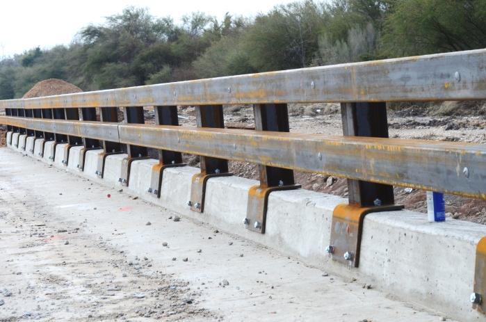
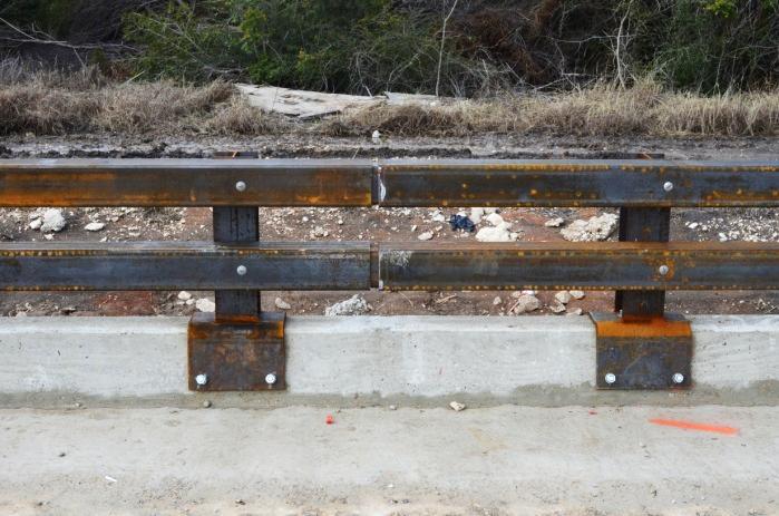
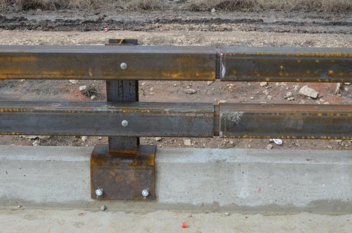
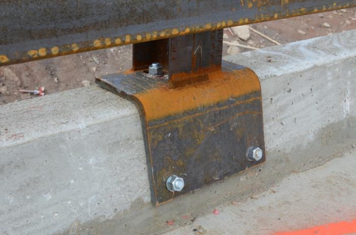
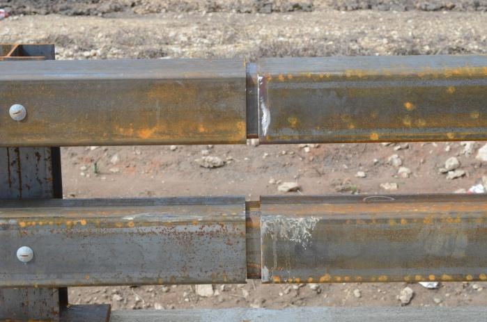
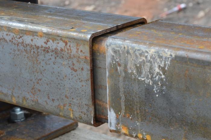
18 Figure 2.3. T131RC Bridge Rail Installation before Test No TR No
19 CHAPTER 3. TEST REQUIREMENTS AND EVALUATION CRITERIA 3.1 CRASH TEST MATRIX According to MASH, two tests are recommended to evaluate longitudinal barriers to test level three (TL-3). MASH Test Designation 3-10: A 2425-lb vehicle impacting the critical impact point (CIP) of the length of need (LON) of the barrier at a nominal impact speed and angle of 62 mi/h and 25 degrees, respectively. This test investigates a barrier s ability to successfully contain and redirect a small passenger vehicle. MASH Test Designation 3-11: A 5000-lb pickup truck impacting the CIP of the LON of the barrier at a nominal impact speed and angle of 62 mi/h and 25 degrees, respectively. This test investigates a barrier s ability to successfully contain and redirect light trucks and sport utility vehicles. Based on the geometry and strength of the new rail design, the project team concluded that Test 3-10 was not warranted. The test reported here corresponds to Test 3-11 of MASH (5000-lb pickup, 62 mi/h, 25 degrees). The crash test and data analysis procedures were in accordance with guidelines presented in MASH. Chapter 4 presents brief descriptions of these procedures. 3.2 EVALUATION CRITERIA The crash test was evaluated in accordance with the criteria presented in MASH. The performance of the T131RC Bridge Rail is judged on the basis of three factors: structural adequacy, occupant risk, and post impact vehicle trajectory. Structural adequacy is judged upon the ability of the T131RC Bridge Rail to contain and redirect the vehicle, or bring the vehicle to a controlled stop in a predictable manner. Occupant risk criteria evaluate the potential risk of hazard to occupants in the impacting vehicle, and, to some extent, other traffic, pedestrians, or workers in construction zones, if applicable. Post-impact vehicle trajectory is assessed to determine potential for secondary impact with other vehicles or fixed objects, creating further risk of injury to occupants of the impacting vehicle and/or risk of injury to occupants in other vehicles. The appropriate safety evaluation criteria from Table 5-1 of MASH were used to evaluate the crash test reported here, and are listed in further detail under the assessment of the crash test. TR No
20
21 CHAPTER 4. CRASH TEST PROCEDURES 4.1 TEST FACILITY The full-scale crash test reported here was performed at Texas A&M Transportation Institute Proving Ground, an International Standards Organization (ISO) accredited laboratory with American Association for Laboratory Accreditation (A2LA) Mechanical Testing certificate The full-scale crash test was performed according to TTI Proving Ground quality procedures and according to the MASH guidelines and standards. The Texas A&M Transportation Institute Proving Ground is a 2000-acre complex of research and training facilities located 10 miles northwest of the main campus of Texas A&M University. The site, formerly an Air Force base, has large expanses of concrete runways and parking aprons well-suited for experimental research and testing in the areas of vehicle performance and handling, vehicle-roadway interaction, durability and efficacy of highway pavements, and safety evaluation of roadside safety hardware. The site selected for construction and testing of the T131RC Bridge Rail evaluated under this project was along the edge of an outof-service apron. The apron consists of an unreinforced jointed-concrete pavement in 12.5 ft 15 ft blocks nominally 6 8 inches deep. The apron is over 50 years old, and the joints have some displacement, but are otherwise flat and level. 4.2 VEHICLE TOW AND GUIDANCE PROCEDURES The test vehicle was towed into the test installation using a steel cable guidance and reverse tow system. A steel cable for guiding the test vehicle was tensioned along the path, anchored at each end, and threaded through an attachment to the front wheel of the test vehicle. An additional steel cable was connected to the test vehicle, passed around a pulley near the impact point, through a pulley on the tow vehicle, and then anchored to the ground such that the tow vehicle moved away from the test site. A two-to-one speed ratio between the test and tow vehicle existed with this system. Just prior to impact with the installation, the test vehicle was released to be unrestrained. The vehicle remained free-wheeling (i.e., no steering or braking inputs) until it cleared the immediate area of the test site, after which the brakes were activated to bring it to a safe and controlled stop. 4.3 DATA ACQUISITION SYSTEMS Vehicle Instrumentation and Data Processing The test vehicle was instrumented with a self-contained, on-board data acquisition system. The signal conditioning and acquisition system is a 16-channel, Tiny Data Acquisition System (TDAS) Pro produced by Diversified Technical Systems, Inc. The accelerometers that measure the x, y, and z axis of vehicle acceleration are strain gauge type with linear millivolt output proportional to acceleration. Angular rate sensors measuring vehicle roll, pitch, and yaw TR No
22 rates are ultra-small size, solid state units designed for crash test service. The TDAS Pro hardware and software conform to the latest SAE J211, Instrumentation for Impact Test. Each of the 16 channels is capable of providing precision amplification, scaling, and filtering based on transducer specifications and calibrations. During the test, data are recorded from each channel at a rate of 10,000 values per second with a resolution of one part in 65,536. Once the data are recorded, internal batteries back these up inside the unit should the primary battery cable be severed. Initial contact of the pressure switch on the vehicle bumper provides a time zero mark and initiates the recording process. After each test, the data are downloaded from the TDAS Pro unit into a laptop computer at the test site. The Test Risk Assessment Program (TRAP) software then processes the raw data to produce detailed reports of the test results. Each of the TDAS Pro units are returned to the factory annually for complete recalibration. Accelerometers and rate transducers are also calibrated annually with traceability to the National Institute for Standards and Technology. TRAP uses the data from the TDAS Pro to compute occupant/compartment impact velocities, time of occupant/compartment impact after vehicle impact, and the highest 10-millisecond (ms) average ridedown acceleration. TRAP calculates change in vehicle velocity at the end of a given impulse period. In addition, the program computes the maximum average accelerations over 50-ms intervals in each of the three directions. For reporting purposes, the data from the vehicle-mounted accelerometers are filtered with a 60-Hz digital filter, and acceleration versus time curves for the longitudinal, lateral, and vertical directions are plotted using TRAP. TRAP uses the data from the yaw, pitch, and roll rate transducers to compute angular displacement in degrees at s intervals and then plots yaw, pitch, and roll versus time. These displacements are in reference to the vehicle-fixed coordinate system with the initial position and orientation of the vehicle-fixed coordinate systems being initial impact Anthropomorphic Dummy Instrumentation According to MASH, the use of a dummy in the 2270P vehicle is optional. Researchers did not use any dummy in the tests with the 2270P vehicle Photographic Instrumentation and Data Processing Photographic coverage of the test included three high-speed cameras: one overhead with a field of view perpendicular to the ground and directly over the impact point; one placed behind the installation at an angle; and a third placed to have a field of view parallel to and aligned with the installation at the downstream end. A flashbulb activated by pressure-sensitive tape switches was positioned on the impacting vehicle to indicate the instant of contact with the installation and was visible from each camera. The films from these high-speed cameras were analyzed on a computer-linked motion analyzer to observe phenomena occurring during the collision and to obtain time-event, displacement, and angular data. A mini-dv camera and still cameras recorded and documented conditions of the test vehicle and installation before and after the test. TR No
23 CHAPTER 5. CRASH TEST RESULTS 5.1 TEST DESIGNATION AND ACTUAL IMPACT CONDITIONS MASH Test 3-11 involves a 2270P vehicle weighing 5000 lb ±100 lb and impacting the bridge rail at an impact speed of 62.2 mi/h ±2.5 mi/h and an angle of 25 degrees ±1.5 degrees. The target impact point was 4.3 ft upstream of the centerline of post 6. The 2007 Dodge Ram 1500 pickup truck used in the test weighed 4985 lb and the actual impact speed and angle were 63.0 mi/h and 24.7 degrees, respectively. The actual impact point was 5 ft upstream of post 6. Impact severity (IS) was kip-ft, which was equal to the target IS. 5.2 TEST VEHICLE A 2007 Dodge Ram 1500 pickup truck, shown in Figures 4 and 5, was used for the crash test. Both the test inertia weight and the gross static weight of the vehicle was 4985 lb. The height to the lower edge of the vehicle bumper was inches, and it was inches to the upper edge of the bumper. The height to the vehicle s center of gravity was inches. Tables C1 and C2 in Appendix C give additional dimensions and information on the vehicle. The pickup was directed into the installation using the cable reverse tow and guidance system, and was released to be free-wheeling and unrestrained just prior to impact. 5.3 WEATHER CONDITIONS The test was performed on the morning of February 14, Weather conditions at the time of testing were: Wind speed: 8 mi/h; Wind direction: 133 degrees with respect to the vehicle (vehicle was traveling in a southwesterly direction); Temperature: 67 F, Relative humidity: 70 percent. 5.4 TEST DESCRIPTION The 2007 Dodge Ram 1500 pickup, traveling at an impact speed of 63.0 mi/h, impacted the T131RC bridge rail 5 ft upstream of post 6 at an impact angle of 24.7 degrees. At s after impact, post 5 began to deflect toward the field side, and posts 6 and 7 began to deflect towards field side at s and s, respectively. The concrete deck around post 5 began to crack at s, and at s on the downstream side. Post 7 began to deflect toward the field side at s, and the concrete deck around posts 6 and 7 began to crack at and s, respectively. At s, the right front tire blew out, and at s, the concrete deck at post 8 began to crack. The rear of the vehicle contacted the bridge rail at s. At s, the vehicle lost contact with the bridge rail. The overhead camera failed, and therefore exit speed and angle were not obtainable. Brakes on the vehicle were not applied, and the vehicle subsequently came to rest 310 ft downstream of impact. Figures D1 and D2 in Appendix D show sequential photographs of the test period. TR No


24 Figure 5.1. Vehicle/Installation Geometrics for Test No TR No


25 Figure 5.2. Vehicle before Test No TR No
26 5.5 DAMAGE TO TEST INSTALLATION Figures 5.3 and 5.4 show damage to the T131RC Bridge Rail after the test. The concrete curb sustained minor damage at posts 2 and 3, and more significant damage at posts 4 through 9. The curb separated 1 inch from the deck at posts 5 and 6. Posts 3 through 8 were leaning toward the field side between 3 degrees to a maximum of 8 degrees at post 6. Length of contact of the vehicle with the bridge rail was 13.2 ft. Maximum permanent deformation was 6.5 inches. The overhead camera failed to trigger, therefore, maximum dynamic deflection and working width were not obtainable. 5.6 VEHICLE DAMAGE Figure 5.5 shows damage that the 2270P vehicle sustained. The right front upper and lower ball joints pulled out of the sockets, and the tie rod, the right upper and lower A-arms, and the right frame rail were deformed. Also damaged were the front bumper, grill, hood, right front tire and wheel rim, right front fender, right front and rear doors, right cab corner, right rear exterior bed, right rear tire and wheel rim, and rear bumper. Maximum exterior crush to the vehicle was 15.0 inches in the side plane at the right front corner at bumper height. Maximum occupant compartment deformation was 0.5 inch in the lateral area across the cab at the left front passenger s kickpanel. Figure 5.6 has photographs of the interior of the vehicle. In Appendix C, Tables C3 and C4 provide exterior crush and occupant compartment measurements. 5.7 OCCUPANT RISK FACTORS Data from the accelerometer, located at the vehicle center of gravity, were digitized for evaluation of occupant risk. In the longitudinal direction, the occupant impact velocity was 15.1 ft/s at s, the highest s occupant ridedown acceleration was 3.4 Gs from to s, and the maximum s average acceleration was 7.0 Gs between and s. In the lateral direction, the occupant impact velocity was 25.9 ft/s at s, the highest s occupant ridedown acceleration was 10.6 Gs from to s, and the maximum s average was 12.8 Gs between and s. Theoretical Head Impact Velocity (THIV) was 32.4 km/h or 9.0 m/s at s; Post-Impact Head Decelerations (PHD) was 10.7 Gs between and s; and Acceleration Severity Index (ASI) was 1.52 between and s. Figure 5.7 summarizes these data and other pertinent information from the test. Figures E1 through E7 in Appendix E present the vehicle angular displacements and accelerations versus time traces. TR No


27 Figure 5.3. Vehicle/Installation after Test No TR No

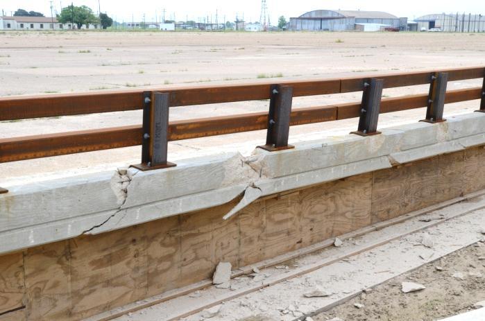
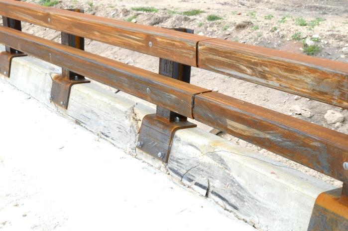
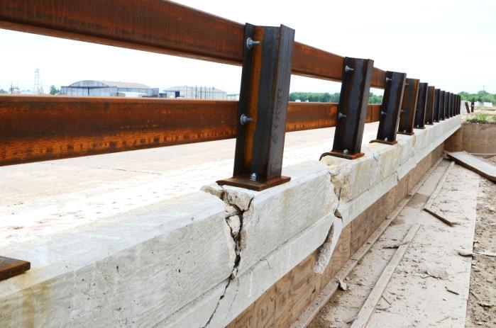
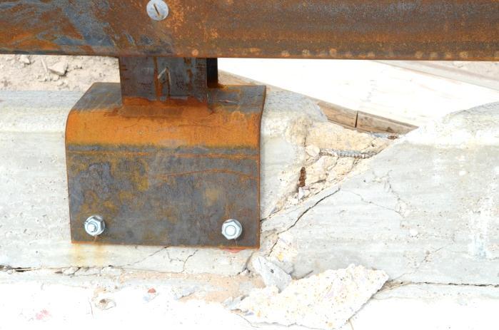
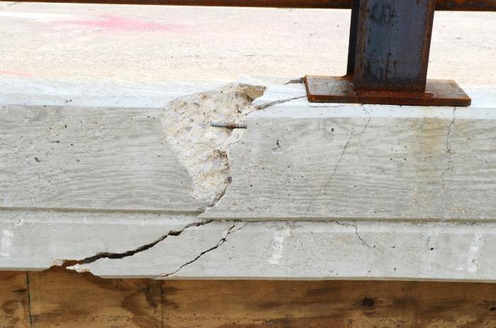
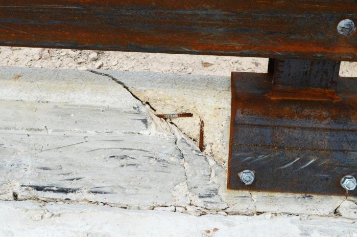
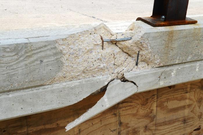
28 Figure 5.4. Installation after Test No TR No


29 Figure 5.5. Vehicle after Test No TR No


30 Figure 5.6. Interior of Vehicle after Test No TR No
 MASH Test 3-11 490022-1 2012-02-14 Bridge Rail TxDOT T131RC Bridge Rail 80 ft Soil Type and Condition.")


31 TR No General Information Test Agency... Test Standard Test No.... TTI Test No.... Test Date... Test Article Type... Name... Installation Length... Material or Key Elements s s s s Texas A&M Transportation Institute (TTI) MASH Test Bridge Rail TxDOT T131RC Bridge Rail 80 ft Soil Type and Condition... Concrete Bridge Deck Test Vehicle Type/Designation P Make and Model Dodge Ram 1500 Curb lb Test Inertial lb Dummy... No dummy Gross Static lb Impact Conditions Speed mi/h Angle degrees Location/Orientation... 5 ft upstream of post 6 Impact Severity kip-ft Exit Conditions Speed... Not obtainable Angle... Not obtainable Occupant Risk Values Impact Velocity Longitudinal ft/s Lateral ft/s Ridedown Accelerations Longitudinal G Lateral G THIV km/h PHD G ASI Max s Average Longitudinal G Lateral G Vertical G Figure 5.7. Summary of Results for MASH Test 3-11 on the T131RC Bridge Rail. Post-Impact Trajectory Stopping Distance ft dwnstrm Vehicle Stability Maximum Yaw Angle degrees Maximum Pitch Angle degrees Maximum Roll Angle degrees Vehicle Snagging... No Vehicle Pocketing... No Test Article Deflections Dynamic... Not obtainable Permanent inches Working Width... Not obtainable Vehicle Damage VDS... 01RFQ4 CDC... 01FREW4 Max. Exterior Deformation inches OCDI... RF Max. Occupant Compartment Deformation inch
32
33 CHAPTER 6. SUMMARY AND CONCLUSIONS 6.1 ASSESSMENT OF TEST RESULTS An assessment of the test based on the applicable MASH safety evaluation criteria is provided below Structural Adequacy A. Test article should contain and redirect the vehicle or bring the vehicle to a controlled stop; the vehicle should not penetrate, underride, or override the installation although controlled lateral deflection of the test article is acceptable. Results: The T131RC bridge rail contained and redirected the 2270P vehicle. The vehicle did not penetrate, underride, or override the installation. Maximum permanent deformation was 6.5 inches. (PASS) Occupant Risk D. Detached elements, fragments, or other debris from the test article should not penetrate or show potential for penetrating the occupant compartment, or present an undue hazard to other traffic, pedestrians, or personnel in a work zone. Deformation of, or intrusions into, the occupant compartment should not exceed limits set forth in Section 5.3 and Appendix E of MASH. (roof 4.0 inches; windshield = 3.0 inches; side windows = no shattering by test article structural member; wheel/foot well/toe pan 9.0 inches; forward of A-pillar 12.0 inches; front side door area above seat 9.0 inches; front side door below seat 12.0 inches; floor pan/transmission tunnel area 12.0 inches) Results: No detached elements, fragments, or other debris were present to penetrate or show potential for penetrating the occupant compartment, nor present hazard to others in the area. (PASS) Maximum occupant compartment deformation was 0.5 inch in the lateral area across the cab at front passenger hip height and the lateral area across the cab at the front passenger side kickpanel. (PASS) F. The vehicle should remain upright during and after collision. The maximum roll and pitch angles are not to exceed 75 degrees. Results: The 2270P vehicle remained upright during and after the collision event. The maximum roll and pitch angles were 23 degrees and 11 degrees, respectively. (PASS) TR No
34 H. Occupant impact velocities should satisfy the following: Longitudinal and Lateral Occupant Impact Velocity Preferred Maximum 30 ft/s 40 ft/s Results: Longitudinal occupant impact velocity was 15.1 ft/s, and lateral occupant impact velocity was 25.9 ft/s. (PASS) I. Occupant ridedown accelerations should satisfy the following: Longitudinal and Lateral Occupant Ridedown Accelerations Preferred Maximum 15.0 Gs Gs Results: Longitudinal ridedown acceleration was 3.4 G, and lateral ridedown acceleration was 10.6 G. (PASS) Vehicle Trajectory For redirective devices, the vehicle shall exit the barrier within the exit box (not less than 32.8 ft). Result: The 2270P vehicle exited within the exit box. (PASS) CONCLUSIONS The T131RC bridge rail performed acceptably for MASH Test 3-11 (see Table 6.1). TR No
35 TR No Table 6.1. Performance Evaluation Summary for MASH Test 3-11 on the T131RC Bridge Rail. Test Agency: Texas A&M Transportation Institute Test No.: Test Date: MASH Test 3-11 Evaluation Criteria Test Results Assessment Structural Adequacy A. Test article should contain and redirect the vehicle or bring the vehicle to a controlled stop; the vehicle should not penetrate, underride, or override the installation although controlled lateral deflection of the test article is acceptable. Occupant Risk D. Detached elements, fragments, or other debris from the test article should not penetrate or show potential for penetrating the occupant compartment, or present an undue hazard to other traffic, pedestrians, or personnel in a work zone. Deformations of, or intrusions into, the occupant compartment should not exceed limits set forth in Section 5.3 and Appendix E of MASH. F. The vehicle should remain upright during and after collision. The maximum roll and pitch angles are not to exceed 75 degrees. H. Longitudinal and lateral occupant impact velocities should fall below the preferred value of 30 ft/s, or at least below the maximum allowable value of 40 ft/s. I. Longitudinal and lateral occupant ridedown accelerations should fall below the preferred value of 15.0 Gs, or at least below the maximum allowable value of Gs. Vehicle Trajectory For redirective devices, the vehicle shall exit the barrier within the exit box (not less than 32.8 ft). The T131RC Bridge Rail contained and redirected the 2270P vehicle. The vehicle did not penetrate, underride, or override the installation. Maximum permanent deformation was 6.5 inches. No detached elements, fragments, or other debris were present to penetrate or show potential for penetrating the occupant compartment, nor pose a hazard to others in the area. Maximum occupant compartment deformation was 0.5 inch in the lateral area across the cab at front passenger hip height and the lateral area across the cab at the front passenger side kickpanel. The 2270P vehicle remained upright during and after the collision event. The maximum roll and pitch angles were 23 degrees and 11 degrees, respectively. Longitudinal occupant impact velocity was 15.1 ft/s, and lateral occupant impact velocity was 25.9 ft/s. Longitudinal ridedown acceleration was 3.4 G, and lateral ridedown acceleration was 10.6 G. The 2270P vehicle exited within the exit box. Pass Pass Pass Pass Pass Pass Pass
36
37 CHAPTER 7. IMPLEMENTATION STATEMENT TxDOT currently uses the TxDOT Type T101RC Bridge Rail, a steel post and beam bridge anchored to the top of concrete curbs. The T101RC Bridge Rail is 27 inches in height and can be anchored to the top of concrete curbs of varying heights. The heights of the posts and the number of bridge rail elements vary depending on the height of the concrete curb. The posts are anchored to the curb using four adhesive anchors. Based on crash testing of similar rail designs of the same height, the researchers believed that the TxDOT Type T101RC Bridge Rail would not meet the MASH TL-3 criteria. The purpose of this portion of the project was to design and crash test a modified design of the TxDOT T101RC Bridge Rail that would meet the strength and safety performance criteria for TL-3 of MASH. A new bridge rail was developed and tested for this project. The TxDOT T131RC Bridge Rail met all the strength and safety performance criteria of MASH. This bridge rail is recommended for implementation on new or retrofit railing applications. TR No
38
39 REFERENCES 1. AASHTO. Manual for Assessing Safety Hardware. American Association of State Highway and Transportation Officials, Washington, D.C., H. E. Ross, Jr., D. L. Sicking, R. A. Zimmer and J. D. Michie. Recommended Procedures for the Safety Performance Evaluation of Highway Features, National Cooperative Highway Research Program Report 350, Transportation Research Board, National Research Council, Washington, D.C., TR No
40
41 APPENDIX A. DETAILS OF THE T131RC BRIDGE RAIL TR No
42 TR No
43 TR No
44 TR No
45 TR No
46 TR No
47 TR No
48 TR No
49 TR No
50
51 APPENDIX B. CERTIFICATION DOCUMENTATION TR No
52 TR No

53 TR No

54 TR No

55 TR No

56 TR No
57 TR No
58 TR No
59 APPENDIX C. TEST VEHICLE PROPERTIES AND INFORMATION Table C1. Vehicle Properties for Test No Date: Test No.: VIN No.: 1D7HA18P Year: 2007 Make: Dodge Model: Ram 1500 Tire Size: P265/70R17 Tire Inflation Pressure: 35 psi Tread Type: All Terrain Odometer: Note any damage to the vehicle prior to test: Denotes accelerometer location. NOTES: Engine Type: V-8 Engine CID: 4.7 liter Transmission Type: x Auto or Manual FWD x RWD 4WD Optional Equipment: Dummy Data: Type: Mass: Seat Position: No dummy Geometry: inches A F K P 2.88 U B G L Q V C H M R W D I N S X E J O T Wheel Center Wheel Well Bottom Frame Height Front Clearance (Front) 5.00 Height - Front Wheel Center Wheel Well Bottom Frame Height Rear Clearance (Rear) Height - Rear RANGE LIMIT: A=78 ±2 inches; C=237 ±13 inches; E=148 ±12 inches; F=39 ±3 inches; G = > 28 inches; H = 63 ±4 inches; O=43 ±4 inches; M+N/2=67 ±1.5 inches GVWR Ratings: Mass: lb Curb Test Inertial Gross Static Front 3700 M front Back 3900 M rear Total 6700 M Total (Allowable Range for TIM and GSM = 5000 lb ±110 lb) Mass Distribution: lb LF: 1457 RF: 1345 LR: 1083 RR: 1100 TR No
60 Table C2. Vertical CG Measurements for Test No Date: Test No.: VIN No.: 1D7HA18P Year: 2007 Make: Dodge Model: Ram 1500 Body Style: Quad Cab Mileage: Engine: 4.7 liter V-8 Transmission: Automatic Fuel Level: Empty Ballast: 76 lb at front of bed (440 lb max) Tire Pressure: Front: 35 psi Rear: 35 psi Size: P265/70R17 Measured Vehicle Weights: (lb) LF: 1433 RF: 1367 Front Axle: 2800 LR: 1075 RR: 1114 Rear Axle: 2189 Left: 2508 Right: 2481 Total: ±110 lb allowed Wheel Base: inches Track: F: 68.5 inches R: 68 inches 148 ±12 inches allowed Track = (F+R)/2 = 67 ±1.5 inches allowed Center of Gravity, SAE J874 Suspension Method X: in Rear of Front Axle (63 ±4 inches allowed) Y: in Left - Right + of Vehicle Centerline Z: in Above Ground (minumum 28.0 inches allowed) Hood Height: 44.5 inches Front Bumper Height: inches 43 ±4 inches allowed Front Overhang: 36.0 inches Rear Bumper Height: inches 39 ±3 inches allowed Overall Length: inches 237 ±13 inches allowed TR No
61 Table C3. Exterior Crush Measurements for Test No Date: Test No.: VIN No.: 1D7HA18P Year: 2007 Make: Dodge Model: Ram 1500 VEHICLE CRUSH MEASUREMENT SHEET 1 Complete When Applicable End Damage Side Damage Undeformed end width Bowing: B1 X1 Corner shift: A1 End shift at frame (CDC) (check one) A2 < 4 inches 4 inches Bowing constant X 1+ X 2 2 B2 X2 = Note: Measure C 1 to C 6 from Driver to Passenger side in Front or Rear impacts Rear to Front in Side Impacts. Direct Damage Specific Impact Plane* of Width** Max*** Field C 1 C 2 C 3 C 4 C 5 C 6 ±D Number C-Measurements (CDC) Crush L** 1 Front plane at bumper ht Side plane at bumper ht Measurements recorded in inches 1 Table taken from National Accident Sampling System (NASS). *Identify the plane at which the C-measurements are taken (e.g., at bumper, above bumper, at sill, above sill, at beltline, etc.) or label adjustments (e.g., free space). Free space value is defined as the distance between the baseline and the original body contour taken at the individual C locations. This may include the following: bumper lead, bumper taper, side protrusion, side taper, etc. Record the value for each C-measurement and maximum crush. **Measure and document on the vehicle diagram the beginning or end of the direct damage width and field L (e.g., side damage with respect to undamaged axle). ***Measure and document on the vehicle diagram the location of the maximum crush. Note: Use as many lines/columns as necessary to describe each damage profile. TR No
62 Table C4. Occupant Compartment Measurements for Test No Date: Test No.: VIN No.: 1D7HA18P Year: 2007 Make: Dodge Model: Ram 1500 *Lateral area across the cab from driver s side kickpanel to passenger s side kickpanel. OCCUPANT COMPARTMENT DEFORMATION MEASUREMENT Before After ( inches ) ( inches ) A A A B B B B B B C C C D D D E E E E F G H I J* TR No


63 APPENDIX D. SEQUENTIAL PHOTOGRAPHS s s s s Figure D1. Sequential Photographs for Test No (Field Side of Bridge Rail). TR No


")

64 0.196s s s s Figure D1. Sequential Photographs for Test No (Field Side of Bridge Rail) (continued). TR No


65 0.000 s s s s s s s s Figure D2. Sequential Photographs for Test No (Frontal View). TR No
66
67 APPENDIX E. VEHICLE ANGULAR DISPLACEMENTS AND ACCELERATIONS TR No Angles (degrees) Roll, Pitch, and Yaw Angles Roll Pitch Yaw Test Number: Test Standard Test No.: MASH Test 3-11 Test Article: T131RC Bridge Rail Test Vehicle: 2007 Dodge Ram 1500 Pickup Inertial Mass: 4985 lb Impact Speed: 63 mph Impact Angle: 24.7 degrees Time (s) Axes are vehicle-fixed. Sequence for determining orientation: 1. Yaw. 2. Pitch. 3. Roll. Figure E1. Vehicle Angular Displacements for Test No
68 TR No Longitudinal Acceleration (G) X Acceleration at CG Time (s) Test Number: Test Standard Test No.: MASH Test 3-11 Test Article: T131RC Bridge Rail Test Vehicle: 2007 Dodge Ram 1500 Pickup Inertial Mass: 4985 lb Impact Speed: 63 mph Impact Angle: 24.7 degrees Time of OIV ( sec) SAE Class 60 Filter 50-msec average Figure E2. Vehicle Longitudinal Accelerometer Trace for Test No (Accelerometer Located at Center of Gravity).
69 TR No Lateral Acceleration (G) Y Acceleration at CG Time (s) Test Number: Test Standard Test No.: MASH Test 3-11 Test Article: T131RC Bridge Rail Test Vehicle: 2007 Dodge Ram 1500 Pickup Inertial Mass: 4985 lb Impact Speed: 63 mph Impact Angle: 24.7 degrees Time of OIV ( sec) SAE Class 60 Filter 50-msec average Figure E3. Vehicle Lateral Accelerometer Trace for Test No (Accelerometer Located at Center of Gravity).
70 TR No Vertical Acceleration (G) Z Acceleration at CG SAE Class 60 Filter 50-msec average Time (s) Test Number: Test Standard Test No.: MASH Test 3-11 Test Article: T131RC Bridge Rail Test Vehicle: 2007 Dodge Ram 1500 Pickup Inertial Mass: 4985 lb Impact Speed: 63 mph Impact Angle: 24.7 degrees Figure E4. Vehicle Vertical Accelerometer Trace for Test No (Accelerometer Located at Center of Gravity).
71 TR No Longitudinal Acceleration (G) X Acceleration Rear of CG SAE Class 60 Filter 50-msec average Time (s) Test Number: Test Standard Test No.: MASH Test 3-11 Test Article: T131RC Bridge Rail Test Vehicle: 2007 Dodge Ram 1500 Pickup Inertial Mass: 4985 lb Impact Speed: 63 mph Impact Angle: 24.7 degrees Impact Speed: 0 Impact Angle: 0 Figure E5. Vehicle Longitudinal Accelerometer Trace for Test No (Accelerometer Located Rear of Center of Gravity).
72 TR No Lateral Acceleration (G) Y Acceleration Rear of CG SAE Class 60 Filter 50-msec average Time (s) Test Number: Test Standard Test No.: MASH Test 3-11 Test Article: T131RC Bridge Rail Test Vehicle: 2007 Dodge Ram 1500 Pickup Inertial Mass: 4985 lb Impact Speed: 63 mph Impact Angle: 24.7 degrees Impact Speed: 0 Impact Angle: 0 Figure E6. Vehicle Lateral Accelerometer Trace for Test No (Accelerometer Located Rear of Center of Gravity).
73 TR No Vertical Acceleration (G) Z Acceleration Rear of CG SAE Class 60 Filter 50-msec average Time (s) Test Number: Test Standard Test No.: MASH Test 3-11 Test Article: T131RC Bridge Rail Test Vehicle: 2007 Dodge Ram 1500 Pickup Inertial Mass: 4985 lb Impact Speed: 63 mph Impact Angle: 24.7 degrees Impact Speed: 0 Impact Angle: 0 Figure E7. Vehicle Vertical Accelerometer Trace for Test No (Accelerometer Located Rear of Center of Gravity).
74
MASH TEST 3-11 OF THE TxDOT T222 BRIDGE RAIL
 TTI: 9-1002-12 MASH TEST 3-11 OF THE TxDOT T222 BRIDGE RAIL ISO 17025 Laboratory Testing Certificate # 2821.01 Crash testing performed at: TTI Proving Ground 3100 SH 47, Building 7091 Bryan, TX 77807 Test
MASH TEST 3-11 OF THE TxDOT SINGLE SLOPE BRIDGE RAIL (TYPE SSTR) ON PAN-FORMED BRIDGE DECK
 ON PAN-FORMED BRIDGE DECK") TTI: 9-1002 MASH TEST 3-11 OF THE TxDOT SINGLE SLOPE BRIDGE RAIL (TYPE SSTR) ON PAN-FORMED BRIDGE DECK ISO 17025 Laboratory Testing Certificate # 2821.01 Crash testing performed at: TTI Proving Ground
TTI: 9-1002 MASH TEST 3-11 OF THE TxDOT SINGLE SLOPE BRIDGE RAIL (TYPE SSTR) ON PAN-FORMED BRIDGE DECK ISO 17025 Laboratory Testing Certificate # 2821.01 Crash testing performed at: TTI Proving Ground
CRASH TEST AND EVALUATION OF 3-FT MOUNTING HEIGHT SIGN SUPPORT SYSTEM
 TTI: 9-1002-15 CRASH TEST AND EVALUATION OF 3-FT MOUNTING HEIGHT SIGN SUPPORT SYSTEM ISO 17025 Laboratory Testing Certificate # 2821.01 Crash testing performed at: TTI Proving Ground 3100 SH 47, Building
A MASH Compliant W-Beam Median Guardrail System
 0 0 0 0 0 A MASH Compliant W-Beam Median Guardrail System By A. Y. Abu-Odeh, R. P. Bligh, W. Odell, A. Meza, and W. L. Menges Submitted: July 0, 0 Word Count:, + ( figures + tables=,000) =, words Authors:
MASH TEST 3-37 OF THE TxDOT 31-INCH W-BEAM DOWNSTREAM ANCHOR TERMINAL
 TTI: 9-1002 MASH TEST 3-37 OF THE TxDOT 31-INCH W-BEAM DOWNSTREAM ANCHOR TERMINAL ISO 17025 Laboratory Testing Certificate # 2821.01 Crash testing performed at: TTI Proving Ground 3100 SH 47, Building
MASH08 TEST 3-11 OF THE ROCKINGHAM PRECAST CONCRETE BARRIER
 Proving Ground Report No. 400001-RPC4 Report Date: July 2009 MASH08 TEST 3-11 OF THE ROCKINGHAM PRECAST CONCRETE BARRIER by C. Eugene Buth, P.E. Research Engineer William F. Williams, P.E. Assistant Research
Form DOT F (8-72) Texas Transportation Institute The Texas A&M University System College Station, Texas
 Texas Transportation Institute The Texas A&M University System College Station, Texas") 1. Report No. FHWA/TX-02/4162-1 Technical Report Documentation Page 2. Government Accession No. 3. Recipient's Catalog No. 4. Title and Subtitle EVALUATION OF TEXAS GRID-SLOT PORTABLE CONCRETE BARRIER
1. Report No. FHWA/TX-02/4162-1 Technical Report Documentation Page 2. Government Accession No. 3. Recipient's Catalog No. 4. Title and Subtitle EVALUATION OF TEXAS GRID-SLOT PORTABLE CONCRETE BARRIER
CRASH TEST AND EVALUATION OF TEMPORARY WOOD SIGN SUPPORT SYSTEM FOR LARGE GUIDE SIGNS
 TTI: 9-1002-15 CRASH TEST AND EVALUATION OF TEMPORARY WOOD SIGN SUPPORT SYSTEM FOR LARGE GUIDE SIGNS ISO 17025 Laboratory Testing Certificate # 2821.01 Crash testing performed at: TTI Proving Ground 3100
MASH TEST 3-21 ON TL-3 THRIE BEAM TRANSITION WITHOUT CURB
 TTI: 9-1002-12 MASH TEST 3-21 ON TL-3 THRIE BEAM TRANSITION WITHOUT CURB ISO 17025 Laboratory Testing Certificate # 2821.01 Crash testing performed at: TTI Proving Ground 3100 SH 47, Building 7091 Bryan,
NCHRP Report 350 Crash Testing and Evaluation of the S-Square Mailbox System
 TTI: 0-5210 NCHRP Report 350 Crash Testing and Evaluation of the S-Square Mailbox System ISO 17025 Laboratory Testing Certificate # 2821.01 Crash testing performed at: TTI Proving Ground 3100 SH 47, Building
Texas Transportation Institute The Texas A&M University System College Station, Texas
 1. Report No. FHWA/TX-05/9-8132-P7 4. Title and Subtitle TL-4 CRASH TESTING OF THE F411 BRIDGE RAIL 2. Government Accession No. 3. Recipient's Catalog No. 5. Report Date October 2004 Technical Report Documentation
MASH TEST 3-10 ON 31-INCH W-BEAM GUARDRAIL WITH STANDARD OFFSET BLOCKS
 TTI: 9-1002 MASH TEST 3-10 ON 31-INCH W-BEAM GUARDRAIL WITH STANDARD OFFSET BLOCKS ISO 17025 Laboratory Testing Certificate # 2821.01 Crash testing performed at: TTI Proving Ground 3100 SH 47, Building
Sponsored by Roadside Safety Research Program Pooled Fund Study No. TPF-5(114)
") Proving Ground Test Report No. 405160-23-2 Test Report Date: February 2012 MASH TEST 3-11 OF THE W-BEAM GUARDRAIL ON LOW-FILL BOX CULVERT by William F. Williams, P.E. Associate Research Engineer and Wanda
Proving Ground Test Report No. 405160-23-2 Test Report Date: February 2012 MASH TEST 3-11 OF THE W-BEAM GUARDRAIL ON LOW-FILL BOX CULVERT by William F. Williams, P.E. Associate Research Engineer and Wanda
Texas Transportation Institute The Texas A&M University System College Station, Texas
 2. Government Accession No. 3. Recipient's Catalog No. 1. Report No. FHWA/TX-03/0-4138-3 4. Title and Subtitle PERFORMANCE OF THE TXDOT T202 (MOD) BRIDGE RAIL REINFORCED WITH FIBER REINFORCED POLYMER BARS
DEVELOPMENT OF A MASH TL-3 MEDIAN BARRIER GATE
 TTI: 9-1002 DEVELOPMENT OF A MASH TL-3 MEDIAN BARRIER GATE ISO 17025 Laboratory Testing Certificate # 2821.01 Crash testing performed at: TTI Proving Ground 3100 SH 47, Building 7091 Bryan, TX 77807 Research/Test
NCHRP Report 350 Test 4-12 of the Modified Thrie Beam Guardrail
 NCHRP Report 350 Test 4-12 of the Modified Thrie Beam Guardrail PUBLICATION NO. FHWA-RD-99-065 DECEMBER 1999 Research, Development, and Technology Turner-Fairbank Highway Research Center 6300 Georgetown
ASTM F TEST M30 ON THE RSS-3000 DROP BEAM SYSTEM
 Proving Ground Test Report No.: 510602-RSS3 Test Report Date: January 2014 ASTM F2656-07 TEST M30 ON THE RSS-3000 DROP BEAM SYSTEM by Dean C. Alberson, Ph.D., P.E. Research Engineer Michael S. Brackin,
Evaluation of Barriers for Very High Speed Roadways
 TTI: 0-6071 Evaluation of Barriers for Very High Speed Roadways ISO 17025 Laboratory Testing Certificate # 2821.01 Crash testing performed at: TTI Proving Ground 3100 SH 47, Building 7091 Bryan, TX 77807
Texas Transportation Institute The Texas A&M University System College Station, Texas
 1. Report No. FHWA/TX-07/0-5527-1 4. Title and Subtitle DEVELOPMENT OF A LOW-PROFILE TO F-SHAPE TRANSITION BARRIER SEGMENT 2. Government Accession No. 3. Recipient's Catalog No. Technical Report Documentation
Texas Transportation Institute The Texas A&M University System College Station, Texas
 1. Report No. FHWA/TX-04/9-8132-1 4. Title and Subtitle TESTING AND EVALUATION OF THE FLORIDA JERSEY SAFETY SHAPED BRIDGE RAIL 2. Government Accession No. 3. Recipient's Catalog No. 5. Report Date February
Manual for Assessing Safety Hardware
 American Association of State Highway and Transportation Officials Manual for Assessing Safety Hardware 2009 vii PREFACE Effective traffic barrier systems, end treatments, crash cushions, breakaway devices,
VULCAN BARRIER TL-3 GENERAL SPECIFICATIONS
 VULCAN BARRIER TL-3 GENERAL SPECIFICATIONS I. GENERAL A. The VULCAN BARRIER TL-3 (VULCAN TL-3) shall be a highly portable and crashworthy longitudinal barrier especially suited for use as a temporary barrier
TEXAS TRANSPORTATION INSTITUTE THE TEXAS A & M UNIVERSITY SYSTEM COLLEGE STATION, TEXAS 77843
 NCHRP REPORT 350 TEST 3-11 OF THE NEW YORK DOT PORTABLE CONCRETE BARRIER WITH I-BEAM CONNECTION (RETEST) by Roger P. Bligh, P.E. Assistant Research Engineer Wanda L. Menges Associate Research Specialist
Technical Report Documentation Page Form DOT F (8-72) Reproduction of completed page authorized
 Reproduction of completed page authorized") 1. Report No. FHWA/TX-05/0-4162-3 4. Title and Subtitle 2. Government Accession No. 3. Recipient's Catalog No. DEVELOPMENT OF LOW-DEFLECTION PRECAST CONCRETE ARRIER 5. Report Date January 2005 Technical
1. Report No. FHWA/TX-05/0-4162-3 4. Title and Subtitle 2. Government Accession No. 3. Recipient's Catalog No. DEVELOPMENT OF LOW-DEFLECTION PRECAST CONCRETE ARRIER 5. Report Date January 2005 Technical
REPORT NUMBER: 301-CAL SAFETY COMPLIANCE TESTING FOR FMVSS 301 FUEL SYSTEM INTEGRITY HONDA MOTOR COMPANY 2007 HONDA ACCORD 4-DOOR SEDAN
 REPORT NUMBER: 301-CAL-07-05 SAFETY COMPLIANCE TESTING FOR FMVSS 301 FUEL SYSTEM INTEGRITY HONDA MOTOR COMPANY 2007 HONDA ACCORD 4-DOOR SEDAN NHTSA NUMBER: C75304 CALSPAN TEST NUMBER: 8832-F301-05 CALSPAN
Advances in Simulating Corrugated Beam Barriers under Vehicular Impact
 13 th International LS-DYNA Users Conference Session: Automotive Advances in Simulating Corrugated Beam Barriers under Vehicular Impact Akram Abu-Odeh Texas A&M Transportation Institute Abstract W-beam
VULCAN BARRIER TL-3 GENERAL SPECIFICATIONS
 VULCAN BARRIER TL-3 GENERAL SPECIFICATIONS I. GENERAL A. The VULCAN BARRIER TL-3 (VULCAN TL-3) shall be a highly portable and crashworthy longitudinal barrier especially suited for use as a temporary barrier
Product Specification. ABSORB 350 TM TL-2 Non-Redirective, Gating, Crash Cushion Applied to Quickchange Moveable Barrier
 TB 000612 Rev. 0 Page 1 of 9 Product Specification ABSORB 350 TM TL-2 Non-Redirective, Gating, Crash Cushion Applied to Quickchange Moveable Barrier I. General The ABSORB 350 TM TL-2 System is a Non-Redirective,
OPTIMIZATION OF THRIE BEAM TERMINAL END SHOE CONNECTION
 TTI: 9-1002-15 OPTIMIZATION OF THRIE BEAM TERMINAL END SHOE CONNECTION ISO 17025 Laboratory Testing Certificate # 2821.01 Pendulum testing performed at: TTI Proving Ground 3100 SH 47, Building 7091 Bryan,
February 8, In Reply Refer To: HSSD/CC-104
 February 8, 2008 200 New Jersey Avenue, SE. Washington, DC 20590 In Reply Refer To: HSSD/CC-04 Barry D. Stephens, P.E. Sr. Vice President Engineering Energy Absorption Systems, Inc. 367 Cincinnati Avenue
STI Project: Barrier Systems, Inc. RTS-QMB Longitudinal Barrier. Page 38 of 40 QBOR1. Appendix F (Continued) Figure F-3
 Figure F-3") Barrier Systems, Inc. RTS-QMB Longitudinal Barrier STI Project: QBOR1 Page 38 of 40 Appendix F (Continued) Figure F-3 t=.500sec 115 meters overall 37.1 Impact Severity (kj).. 141.6 Angle (deg).. 25 Speed
Barrier Systems, Inc. RTS-QMB Longitudinal Barrier STI Project: QBOR1 Page 38 of 40 Appendix F (Continued) Figure F-3 t=.500sec 115 meters overall 37.1 Impact Severity (kj).. 141.6 Angle (deg).. 25 Speed
TEXAS TRANSPORTATION INSTITUTE THE TEXAS A & M UNIVERSITY SYSTEM COLLEGE STATION, TEXAS 77843
 NCHRP REPORT 350 TEST 3-11 OF THE STEEL-BACKED TIMBER GUARDRAIL by D. Lance Bullard, Jr., P.E. Associate Research Engineer Wanda L. Menges Associate Research Specialist and Sandra K. Schoeneman Research
CRASH TESTING OF RSA/K&C ANTI-RAM FOUNDATION BOLLARD PAD IN ACCORDANCE WITH U.S. DEPARTMENT OF STATE DIPLOMATIC SECURITY SD-STD-02.
 CRASH TESTING OF RSA/K&C ANTI-RAM FOUNDATION BOLLARD PAD IN ACCORDANCE WITH U.S. DEPARTMENT OF STATE DIPLOMATIC SECURITY SD-STD-02.01 REVISION A Prepared for RSA Protective Technologies, LLC FINAL REPORT
Virginia Department of Transportation
 TEST REPORT FOR: Virginia Department of Transportation SKT SP 350 50 (15.24 m) System PREPARED FOR: Virginia Department of Transportation 1401 E. Broad St. Richmond, VA 23219 TEST REPORT NUMBER: REPORT
TEXAS TRANSPORTATION INSTITUTE THE TEXAS A & M UNIVERSITY SYSTEM COLLEGE STATION, TEXAS
 NCHRP REPORT 350 TEST 4-21 OF THE ALASKA MULTI-STATE BRIDGE RAIL THRIE-BEAM TRANSITION by C. Eugene Buth Senior Research Engineer William F. Williams Assistant Research Engineer Wanda L. Menges Associate
VERIFICATION & VALIDATION REPORT of MGS Barrier Impact with 1100C Vehicle Using Toyota Yaris Coarse FE Model
 VERIFICATION & VALIDATION REPORT of MGS Barrier Impact with 1100C Vehicle Using Toyota Yaris Coarse FE Model CCSA VALIDATION/VERIFICATION REPORT Page 1 of 4 Project: CCSA Longitudinal Barriers on Curved,
MASH 2016 Implementation: What, When and Why
 MASH 2016 Implementation: What, When and Why Roger P. Bligh, Ph.D., P.E. Senior Research Engineer Texas A&M Transportation Institute June 7, 2016 2016 Traffic Safety Conference College Station, Texas Outline
GUARDRAIL TESTING MODIFIED ECCENTRIC LOADER TERMINAL (MELT) AT NCHRP 350 TL-2. Dean C. Alberson, Wanda L. Menges, and Rebecca R.
 AT NCHRP 350 TL-2. Dean C. Alberson, Wanda L. Menges, and Rebecca R.") GUARDRAIL TESTING MODIFIED ECCENTRIC LOADER TERMINAL (MELT) AT NCHRP 350 TL-2 Dean C. Alberson, Wanda L. Menges, and Rebecca R. Haug Prepared for The New England Transportation Consortium July 2002 NETCR
GUARDRAIL TESTING MODIFIED ECCENTRIC LOADER TERMINAL (MELT) AT NCHRP 350 TL-2 Dean C. Alberson, Wanda L. Menges, and Rebecca R. Haug Prepared for The New England Transportation Consortium July 2002 NETCR
CRASH TEST REPORT FOR PERIMETER BARRIERS AND GATES TESTED TO SD-STD-02.01, REVISION A, MARCH Anti-Ram Bollards
 CRASH TEST REPORT FOR PERIMETER BARRIERS AND GATES TESTED TO SD-STD-02.01, REVISION A, MARCH 2003 Anti-Ram Bollards Prepared for: RSA Protective Technologies, LLC 1573 Mimosa Court Upland, CA 91784 Test
Universal TAU-IIR Redirective, Non-Gating, Crash Cushion
 TB 110927 Rev. 0 Page 1 of 5 Product Specification Universal TAU-IIR Redirective, Non-Gating, Crash Cushion I. General The Universal TAU-IIR system is a Redirective, Non-Gating Crash Cushion in accordance
Evaluation and Design of ODOT s Type 5 Guardrail with Tubular Backup
 Evaluation and Design of ODOT s Type 5 Guardrail with Tubular Backup Draft Final Report Chuck A. Plaxico, Ph.D. James C. Kennedy, Jr., Ph.D. Charles R. Miele, P.E. for the Ohio Department of Transportation
CRASH TEST REPORT FOR PERIMETER BARRIERS AND GATES TESTED TO SD-STD-02.01, REVISION A, MARCH Anti-Ram Bollards
 CRASH TEST REPORT FOR PERIMETER BARRIERS AND GATES TESTED TO SD-STD-02.01, REVISION A, MARCH 2003 Anti-Ram Bollards Prepared for: RSA Protective Technologies, LLC 1573 Mimosa Court Upland, CA 91784 Test
TEXAS TRANSPORTATION INSTITUTE THE TEXAS A & M UNIVERSITY SYSTEM COLLEGE STATION, TEXAS 77843
 NCHRP REPORT 350 ASSESSMENT OF EXISTING ROADSIDE SAFETY HARDWARE by C. Eugene Buth, P.E. Senior Research Engineer Wanda L. Menges Associate Research Specialist and Sandra K. Schoeneman Research Associate
July 10, Refer to: HSA-10/CC-78A
 July 10, 2003 Refer to: HSA-10/CC-78A Barry D. Stephens, P.E. Senior Vice President of Engineering ENERGY ABSORPTION Systems, Inc. 3617 Cincinnati Avenue Rocklin, California 95765 Dear Mr. Stephens: Your
PERFORMANCE EVALUATION OF THE FREE-STANDING TEMPORARY BARRIER UPDATE TO NCHRP 350 TEST NO WITH 28" C.G. HEIGHT (2214TB-2)
") PERFORMANCE EVALUATION OF THE FREE-STANDING TEMPORARY BARRIER UPDATE TO NCHRP 350 TEST NO. 3-11 WITH 28" C.G. HEIGHT (2214TB-2) Submitted by Karla A. Polivka, M.S.M.E., E.I.T. Research Associate Engineer
PERFORMANCE EVALUATION OF THE FREE-STANDING TEMPORARY BARRIER UPDATE TO NCHRP 350 TEST NO. 3-11 WITH 28" C.G. HEIGHT (2214TB-2) Submitted by Karla A. Polivka, M.S.M.E., E.I.T. Research Associate Engineer
REPORT NUMBER: 301-MGA SAFETY COMPLIANCE TESTING FOR FMVSS 301R FUEL SYSTEM INTEGRITY REAR IMPACT
 REPORT NUMBER: 301-MGA-2010-007 SAFETY COMPLIANCE TESTING FOR FMVSS 301R FUEL SYSTEM INTEGRITY REAR IMPACT NISSAN MOTOR COMPANY LTD 2010 NISSAN CUBE NHTSA NUMBER: CA5205 PREPARED BY: MGA RESEARCH CORPORATION
June 5, In Reply Refer To: HSSD/B-178. Mr. Kevin K. Groeneweg Mobile Barriers LLC Genesee Trail Road Golden, CO Dear Mr.
 June 5, 2008 1200 New Jersey Avenue, SE. Washington, DC 20590 In Reply Refer To: HSSD/B-178 Mr. Kevin K. Groeneweg Mobile Barriers LLC 24918 Genesee Trail Road Golden, CO 80401 Dear Mr. Groeneweg: This
Development of Combination Pedestrian-Traffic Bridge Railings
 TRANSPORTATION RESEARCH RECORD 1468 41 Development of Combination Pedestrian-Traffic Bridge Railings D. LANCE BULLARD, JR., WANDA L. MENGES, AND C. EUGENE BUTH Two bridge railing designs have been developed
PERFORMANCE EVALUATION OF THE PERMANENT NEW JERSEY SAFETY SHAPE BARRIER UPDATE TO NCHRP 350 TEST NO (2214NJ-2)
") PERFORMANCE EVALUATION OF THE PERMANENT NEW JERSEY SAFETY SHAPE BARRIER UPDATE TO NCHRP 350 TEST NO. 4-12 (2214NJ-2) Submitted by Karla A. Polivka, M.S.M.E., E.I.T. Research Associate Engineer Dean L.
PERFORMANCE EVALUATION OF THE PERMANENT NEW JERSEY SAFETY SHAPE BARRIER UPDATE TO NCHRP 350 TEST NO. 4-12 (2214NJ-2) Submitted by Karla A. Polivka, M.S.M.E., E.I.T. Research Associate Engineer Dean L.
SAFETY COMPLIANCE TESTING FOR FMVSS NO. 214S SIDE IMPACT PROTECTION (STATIC)
") REPORT NUMBER 214-GTL-09-002 SAFETY COMPLIANCE TESTING FOR S SIDE IMPACT PROTECTION (STATIC) MAZDA MOTOR CORPORATION 2009 MAZDA 3, PASSENGER CAR NHTSA NO. C95400 GENERAL TESTING LABORATORIES, INC. 1623
REPORT NUMBER 214-GTL-09-002 SAFETY COMPLIANCE TESTING FOR S SIDE IMPACT PROTECTION (STATIC) MAZDA MOTOR CORPORATION 2009 MAZDA 3, PASSENGER CAR NHTSA NO. C95400 GENERAL TESTING LABORATORIES, INC. 1623
PERFORMANCE EVALUATION OF THE FREE-STANDING TEMPORARY BARRIER UPDATE TO NCHRP 350 TEST NO (2214TB-1)
") PERFORMANCE EVALUATION OF THE FREE-STANDING TEMPORARY BARRIER UPDATE TO NCHRP 350 TEST NO. 3-11 (2214TB-1) Submitted by Karla A. Polivka, M.S.M.E., E.I.T. Research Associate Engineer Dean L. Sicking, Ph.D.,
PERFORMANCE EVALUATION OF THE FREE-STANDING TEMPORARY BARRIER UPDATE TO NCHRP 350 TEST NO. 3-11 (2214TB-1) Submitted by Karla A. Polivka, M.S.M.E., E.I.T. Research Associate Engineer Dean L. Sicking, Ph.D.,
Remote Combination Adaptive Driving Equipment Investigation Dynamic Science, Inc. (DSI), Case Number G 1990 Ford Bronco Arizona October
, Case Number G 1990 Ford Bronco Arizona October") Remote Combination Adaptive Driving Equipment Investigation Dynamic Science, Inc. (DSI), Case Number 2007-76-131G 1990 Ford Bronco Arizona October 2007 This document is disseminated under the sponsorship
Remote Combination Adaptive Driving Equipment Investigation Dynamic Science, Inc. (DSI), Case Number 2007-76-131G 1990 Ford Bronco Arizona October 2007 This document is disseminated under the sponsorship
PERFORMANCE EVALUATION OF THE MODIFIED G4(1S) GUARDRAIL UPDATE TO NCHRP 350 TEST NO WITH 28" C.G. HEIGHT (2214WB-2)
 GUARDRAIL UPDATE TO NCHRP 350 TEST NO WITH 28 C.G. HEIGHT (2214WB-2)") PERFORMANCE EVALUATION OF THE MODIFIED G4(1S) GUARDRAIL UPDATE TO NCHRP 350 TEST NO. 3-11 WITH 28" C.G. HEIGHT (2214WB-2) Submitted by Karla A. Polivka, M.S.M.E., E.I.T. Research Associate Engineer Dean
PERFORMANCE EVALUATION OF THE MODIFIED G4(1S) GUARDRAIL UPDATE TO NCHRP 350 TEST NO. 3-11 WITH 28" C.G. HEIGHT (2214WB-2) Submitted by Karla A. Polivka, M.S.M.E., E.I.T. Research Associate Engineer Dean
REPORT NUMBER: 301-MGA SAFETY COMPLIANCE TESTING FOR FMVSS 301R FUEL SYSTEM INTEGRITY REAR IMPACT
 REPORT NUMBER: 301-MGA-2011-008 SAFETY COMPLIANCE TESTING FOR FMVSS 301R FUEL SYSTEM INTEGRITY REAR IMPACT MAZDA MOTOR CORPORATION 2011 MAZDA 2 SPORT MT NHTSA NUMBER: CB5400 PREPARED BY: MGA RESEARCH CORPORATION
REPORT NUMBER: 301-CAL SAFETY COMPLIANCE TESTING FOR FMVSS 301 FUEL SYSTEM INTEGRITY REAR IMPACT FORD MOTOR COMPANY 2009 FORD F150 2-DOOR PICKUP
 REPORT NUMBER: 301-CAL-09-03 SAFETY COMPLIANCE TESTING FOR FMVSS 301 FUEL SYSTEM INTEGRITY REAR IMPACT FORD MOTOR COMPANY 2009 FORD F150 2-DOOR PICKUP NHTSA NUMBER: C90206 CALSPAN TRANSPORTATION SCIENCES
CRASH TEST OF MILE POST MARKER. T. J. Hirsch Research Engineer. and. Eugene Buth Assistant Research Engineer. Research Report Number 146-8
 CRASH TEST OF MILE POST MARKER by T. J. Hirsch Research Engineer and Eugene Buth Assistant Research Engineer Research Report Number 146-8 Studies of Field Adaption of Impact Attenuation Systems Research
REPORT NUMBER: 301-MGA SAFETY COMPLIANCE TESTING FOR FMVSS 301R FUEL SYSTEM INTEGRITY REAR IMPACT
 REPORT NUMBER: 301-MGA-2007-002 SAFETY COMPLIANCE TESTING FOR FMVSS 301R FUEL SYSTEM INTEGRITY REAR IMPACT NISSAN MOTOR CO., LTD. 2006 NISSAN PATHFINDER LE 4X2 NHTSA NUMBER: C65200 PREPARED BY: MGA RESEARCH
REPORT NO. TR-P NC SAFETY COMPLIANCE TESTING FOR FMVSS 223 REAR IMPACT GUARDS 2007 TRANSFREIGHT TECHNOLOGY NHTSA NO.
 REPORT NO. SAFETY COMPLIANCE TESTING FOR FMVSS 223 REAR IMPACT GUARDS 2007 TRANSFREIGHT TECHNOLOGY NHTSA NO. RIG 009 PREPARED BY: KARCO ENGINEERING, LLC. 9270 HOLLY ROAD ADELANTO, CALIFORNIA 92301 SEPTEMBER
REPORT NUMBER: 301-CAL SAFETY COMPLIANCE TESTING FOR FMVSS 301 FUEL SYSTEM INTEGRITY REAR IMPACT MAZDA MOTOR CORPORATION 2008 MAZDA CX-9 SUV
 REPORT NUMBER: 301-CAL-08-03 SAFETY COMPLIANCE TESTING FOR FMVSS 301 FUEL SYSTEM INTEGRITY REAR IMPACT MAZDA MOTOR CORPORATION 2008 MAZDA CX-9 SUV NHTSA NUMBER: C85401 CALSPAN TRANSPORTATION SCIENCES CENTER
REPORT NUMBER: 301-MGA SAFETY COMPLIANCE TESTING FOR FMVSS 301R FUEL SYSTEM INTEGRITY REAR IMPACT
 REPORT NUMBER: 301-MGA-2010-005 SAFETY COMPLIANCE TESTING FOR FMVSS 301R FUEL SYSTEM INTEGRITY REAR IMPACT NISSAN MOTOR COMPANY LTD 2010 NISSAN CUBE NHTSA NUMBER: CA5201 PREPARED BY: MGA RESEARCH CORPORATION
FAAC International, Inc.
 TEST REPORT FOR: FAAC International, Inc. J 355 HA M30 (K4) Bollard TESTED TO: ASTM F 2656-07 Standard Test Method for Vehicle Crash Testing of Perimeter Barriers Test M30 PREPARED FOR: FAAC International,
BarrierGate. General Specifications. Manual Operations General Specifications
 BarrierGate General Specifications Manual Operations General Specifications BarrierGate GENERAL SPECIFICATIONS I. GENERAL A. The BarrierGate system (the gate) shall be designed and manufactured by Energy
NCHRP REPORT 350 TEST 4-12 OF THE MASSACHUSETTS S3-TL4 STEEL BRIDGE RAILING MOUNTED ON CURB AND SIDEWALK
 TEXAS TRANSPORTATION INSTITUTE NCHRP REPORT 350 TEST 4-12 OF THE MASSACHUSETTS S3-TL4 STEEL BRIDGE RAILING MOUNTED ON CURB AND SIDEWALK by C. Eugene Buth Research Engineer and Wanda L. Menges Associate
REPORT NUMBER: 301-CAL SAFETY COMPLIANCE TESTING FOR FMVSS 301 FUEL SYSTEM INTEGRITY REAR IMPACT
 REPORT NUMBER: 301-CAL-09-01 SAFETY COMPLIANCE TESTING FOR FMVSS 301 FUEL SYSTEM INTEGRITY REAR IMPACT HYUNDAI MOTOR COMPANY 2009 HYUNDAI ACCENT 4-DOOR SEDAN NHTSA NUMBER: C90503 CALSPAN TRANSPORTATION
Wyoming Road Closure Gate
 38 TRANSPORTATION RESEARCH RECORD 1528 Wyoming Road Closure Gate KING K. MAK, ROGER P. BLIGH, AND WILLIAM B. WILSON Road closure gates are used to close certain highways when driving conditions become
CRASH TESTING AND EVALUATION OF WORK ZONE TRAFFIC CONTROL DEVICES
 Paper No. 980627 CRASH TESTING AND EVALUATION OF WORK ZONE TRAFFIC CONTROL DEVICES by King K. Mak Phone: 210-698-2068 Fax: 210-698-2068 e-mail: king@tti3a.tamu.edu Texas Transportation Institute The Texas
REPORT NUMBER: 305-MGA
 REPORT NUMBER: 305-MGA-2011-004 SAFETY COMPLIANCE TESTING FOR FMVSS 305 Electric Powered Vehicles: Electrolyte Spillage and Electrical Shock Protection NISSAN MOTOR CO., LTD. 2011 NISSAN LEAF 5-DR HATCHBACK
Evaluation of the Midwest Guardrail System Stiffness Transition with Curb
 Duplication for publication or sale is strictly prohibited without prior written permission of the Transportation Research Board Paper No. -0 Evaluation of the Midwest Guardrail System Stiffness Transition
SUMMARY CHANGES FOR NCHRP REPORT 350 GUIDELINES [NCHRP (02)] Keith A. Cota, Chairman Technical Committee on Roadside Safety June 14, 2007
![SUMMARY CHANGES FOR NCHRP REPORT 350 GUIDELINES [NCHRP (02)] Keith A. Cota, Chairman Technical Committee on Roadside Safety June 14, 2007](/thumbs/87/97351925.jpg "SUMMARY CHANGES FOR NCHRP REPORT 350 GUIDELINES [NCHRP (02)] Keith A. Cota, Chairman Technical Committee on Roadside Safety June 14, 2007") SUMMARY CHANGES FOR NCHRP REPORT 350 GUIDELINES [NCHRP 22-14 (02)] Keith A. Cota, Chairman Technical Committee on Roadside Safety June 14, 2007 BACKGROUND Circular 482 (1962) First full scale crash test
SUMMARY CHANGES FOR NCHRP REPORT 350 GUIDELINES [NCHRP 22-14 (02)] Keith A. Cota, Chairman Technical Committee on Roadside Safety June 14, 2007 BACKGROUND Circular 482 (1962) First full scale crash test
Remote, Redesigned Air Bag Special Study Dynamic Science, Inc., Case Number ( C) 1998 Nissan Altima Texas August/1998
 1998 Nissan Altima Texas August/1998") Remote, Redesigned Air Bag Special Study Dynamic Science, Inc., Case Number ( 1998-49-136C) 1998 Nissan Altima Texas August/1998 Technical Report Documentation Page 1. Report No. 2. Government Accession
Remote, Redesigned Air Bag Special Study Dynamic Science, Inc., Case Number ( 1998-49-136C) 1998 Nissan Altima Texas August/1998 Technical Report Documentation Page 1. Report No. 2. Government Accession
SAFETY COMPLIANCE TESTING FOR FMVSS 225 Child Restraint Anchorage Systems
 FINAL REPORT NUMBER 225-MGA-06-002 SAFETY COMPLIANCE TESTING FOR FMVSS 225 GENERAL MOTORS CORPORATION 2006 HUMMER H3 NHTSA No. C60102 MGA RESEARCH CORPORATION 446 Executive Drive Troy, Michigan 48083 Test
AASHTO Manual for Assessing Safety Hardware, AASHTO/FHWA Joint Implementation Plan Standing Committee on Highways September 24, 2015
 AASHTO Manual for Assessing Safety Hardware, 2015 AASHTO/FHWA Joint Implementation Plan Standing Committee on Highways September 24, 2015 Full Scale MASH Crash Tests (NCHRP 22-14(02)) Conducted several
1962: HRCS Circular 482 one-page document, specified vehicle mass, impact speed, and approach angle for crash tests.
 1 2 3 1962: HRCS Circular 482 one-page document, specified vehicle mass, impact speed, and approach angle for crash tests. 1973: NCHRP Report 153 16-page document, based on technical input from 70+ individuals
SAFETY COMPLIANCE TESTING FOR FMVSS 225 Child Restraint Anchorage Systems
 FINAL REPORT NUMBER 225-MGA-06-007 SAFETY COMPLIANCE TESTING FOR FMVSS 225 TOYOTA MOTOR CORPORATION 2006 TOYOTA HIGHLANDER NHTSA No. C65101 MGA RESEARCH CORPORATION 446 Executive Drive Troy, Michigan 48083
W-Beam Guiderail Transition from Light to Heavy Posts
 TRANSPORTATION RESEARCH RECORD 1198 55 W-Beam Guiderail Transition from Light to Heavy Posts DONALD G. HERRING AND JAMES E. BRYDEN Two full-scale crash tests evaluated a transition between lightand heavy-post
Assessing Options for Improving Roadside Barrier Crashworthiness
 13 th International LS-DYNA Users Conference Session: Simulation Assessing Options for Improving Roadside Barrier Crashworthiness D. Marzougui, C.D. Kan, and K.S. Opiela Center for Collision Safety and
Crash Testing Growth Common Roadside Hardware Systems Draft FHWA and AASHTO Requirements for Implementing MASH 2015
 64 th Annual Illinois Traffic Safety and Engineering Conference October 14, 2015 Crash Testing Growth Common Roadside Hardware Systems Draft FHWA and AASHTO Requirements for Implementing MASH 2015 1 https://www.youtube.com/watch?feature
Performance Level 1 Bridge Railings
 80 TRANSPORTATION RESEARCH RECORD 1500 Performance Level 1 Bridge Railings DEAN C. ALBERSON, WANDA L. MENGES, AND C. EUGENE BUTH Twenty-three states, FHW A, and the District of Columbia sponsored the project
COMPLIANCE TESTING FOR FMVSS 207 SEATING SYSTEMS
 REPORT NO. COMPLIANCE TESTING FOR FMVSS 207 SEATING SYSTEMS 2008 CHEVROLET IMPALA 4-DOOR NHTSA NO.C80102 PREPARED BY: KARCO ENGINEERING, LLC 9270 HOLLY ROAD ADELANTO, CALIFORNIA 92301 September 24, 2008
RSA Protective Technologies
 TEST REPORT FOR: RSA Protective Technologies K12 Surface Mounted Bollard System TESTED TO: ASTM F 2656-07 Standard Test Method for Vehicle Crash Testing of Perimeter Barriers Test M50 PREPARED FOR: Battelle
I. 22. Price. Technical Report Documentation Page
 1. Report No. TX-00/1914-5 1 2. Government Accession No. 4. Title and Subtitle THE 1995 PERFORMANCE RESULTS FOR SLOPE PROTECTION PRODUCTS, HYDRAULIC MULCHES, AND FLEXIBLE CHANNEL LINERS Technical Report
ROBUST PROJECT Norwegian Public Roads Administration / Force Technology Norway AS
 ROBUST PROJECT Norwegian Public Roads Administration / Force Technology Norway AS Evaluation of small car - RM_R1 - prepared by Politecnico di Milano Volume 1 of 1 January 2006 Doc. No.: ROBUST-5-002/TR-2004-0039
Evaluation of the Midwest Guardrail System stiffness transition with curb
 University of Nebraska - Lincoln DigitalCommons@University of Nebraska - Lincoln Civil Engineering Faculty Publications Civil Engineering 2016 Evaluation of the Midwest Guardrail System stiffness transition
Development of Turning Templates for Various Design Vehicles
 Transportation Kentucky Transportation Center Research Report University of Kentucky Year 1991 Development of Turning Templates for Various Design Vehicles Kenneth R. Agent Jerry G. Pigman University of
SAFETY PERFORMANCE OF WORK-ZONE DEVICES UNDER MASH TESTING
 SAFETY PERFORMANCE OF WORK-ZONE DEVICES UNDER MASH TESTING Schmidt, Faller, Lechtenberg, Sicking, Holloway Midwest Roadside Safety Facility Nebraska Transportation Center University of Nebraska-Lincoln
Technical Report Documentation Page 2. Government Accession No. 3. Recipient's Catalog No. 1. Report No. FHWA/TX-09/
 1. Report No. FHWA/TX-09/0-6071-1 4. Title and Subtitle ANALYSIS OF ROADSIDE SAFETY DEVICES FOR USE ON VERY HIGH-SPEED ROADWAYS Technical Report Documentation Page 2. Government Accession No. 3. Recipient's
SAFETY COMPLIANCE TESTING FOR FMVSS 225 Child Restraint Anchorage Systems
 FINAL REPORT NUMBER 225-MGA-10-003 SAFETY COMPLIANCE TESTING FOR FMVSS 225 NISSAN MOTORS 2010 NISSAN ROGUE NHTSA No. CA5202 MGA RESEARCH CORPORATION 446 Executive Drive Troy, Michigan 48083 Test Date:
Midwest Guardrail System Without Blockouts
 Duplication for publication or sale is strictly prohibited without prior written permission of the Transportation Research Board Paper No. 13-0418 Midwest Guardrail System Without Blockouts by John D.
PR V2. Submitted by. Professor MIDWEST Vine Street (402) Submitted to
 Submitted to") FINAL REPORT PR4893118-V2 ZONE OF INTRUSION STUDY Submitted by John D. Reid, Ph.D. Professor Dean L.. Sicking, Ph.D., P.E. Professorr and MwRSF Director MIDWEST ROADSIDE SAFETY FACILITY University of Nebraska-Lincoln
FINAL REPORT PR4893118-V2 ZONE OF INTRUSION STUDY Submitted by John D. Reid, Ph.D. Professor Dean L.. Sicking, Ph.D., P.E. Professorr and MwRSF Director MIDWEST ROADSIDE SAFETY FACILITY University of Nebraska-Lincoln
Pedestrian Autonomous Emergency Braking Test Protocol (Version II) February 2019
 February 2019") Pedestrian Autonomous Emergency Braking Test Protocol (Version II) February 2019 Contents DOCUMENT REVISION HISTORY... ii SUMMARY... 1 TEST ENVIRONMENT... 2 Surface and Markings... 2 Surroundings... 2
Pedestrian Autonomous Emergency Braking Test Protocol (Version II) February 2019 Contents DOCUMENT REVISION HISTORY... ii SUMMARY... 1 TEST ENVIRONMENT... 2 Surface and Markings... 2 Surroundings... 2
W-Beam Approach Treatment at Bridge Rail Ends Near Intersecting Roadways
 TRANSPORTATION RESEARCH RECORD 1133 51 W-Beam Approach Treatment at Bridge Rail Ends Near Intersecting Roadways M. E. BRONSTAD, M. H. RAY, J. B. MAYER, JR., AND c. F. MCDEVITT This paper is concerned with
KENTUCKY TRANSPORTATION CENTER
 Research Report KTC-08-10/UI56-07-1F KENTUCKY TRANSPORTATION CENTER EVALUATION OF 70 MPH SPEED LIMIT IN KENTUCKY OUR MISSION We provide services to the transportation community through research, technology
COMPARISON OF THE IMPACT PERFORMANCE OF THE G4(1W) AND G4(2W) GUARDRAIL SYSTEMS UNDER NCHRP REPORT 350 TEST 3-11 CONDITIONS
 AND G4(2W) GUARDRAIL SYSTEMS UNDER NCHRP REPORT 350 TEST 3-11 CONDITIONS") Paper No. 00-0525 COMPARISON OF THE IMPACT PERFORMANCE OF THE G4(1W) AND G4(2W) GUARDRAIL SYSTEMS UNDER NCHRP REPORT 350 TEST 3-11 CONDITIONS by Chuck A. Plaxico Associate Research Engineer Worcester Polytechnic
Paper No. 00-0525 COMPARISON OF THE IMPACT PERFORMANCE OF THE G4(1W) AND G4(2W) GUARDRAIL SYSTEMS UNDER NCHRP REPORT 350 TEST 3-11 CONDITIONS by Chuck A. Plaxico Associate Research Engineer Worcester Polytechnic
Appendix D. Figure D-1. ENCLOSURE 1 (4 Pages) SafeGuard TM Gate System
 SafeGuard TM Gate System") Appendix D Figure D-1 SafeGuard TM Gate System ENCLOSURE 1 (4 Pages) Appendix D (Continued) Figure D-4 SafeGuard TM Gate System Appendix D (Continued) Figure D-9 SafeGuardTM Gate System Page D-9 Figure
Appendix D Figure D-1 SafeGuard TM Gate System ENCLOSURE 1 (4 Pages) Appendix D (Continued) Figure D-4 SafeGuard TM Gate System Appendix D (Continued) Figure D-9 SafeGuardTM Gate System Page D-9 Figure
SAFETY COMPLIANCE TESTING FOR FMVSS 202a Head Restraints
 FINAL REPORT NUMBER 202a-MGA-10-003 SAFETY COMPLIANCE TESTING FOR FMVSS 202a FORD MOTOR COMPANY 2010 Lincoln MKT MPV NHTSA No. CA0213 MGA RESEARCH CORPORATION 446 Executive Drive Troy, Michigan 48083 Test
Safe-Stop TMA (Truck Mounted Attenuator) GENERAL SPECIFICATIONS
 GENERAL SPECIFICATIONS") Safe-Stop TMA (Truck Mounted Attenuator) GENERAL SPECIFICATIONS I. GENERAL A. All Safe-Stop Truck Mounted Attenuators (Safe-Stop TMA) shall be designed and manufactured by Energy Absorption Systems, Incorporated,
Safe-Stop TMA (Truck Mounted Attenuator) GENERAL SPECIFICATIONS I. GENERAL A. All Safe-Stop Truck Mounted Attenuators (Safe-Stop TMA) shall be designed and manufactured by Energy Absorption Systems, Incorporated,
Electronic Reporting
 Electronic Reporting Test TB31 of BS EN 1317 Parts 1 & 2 Test Number: TRL068 Trief Kerb and Pavement (Opinions and interpretations do not form part of this report.) TEST REPORT VIDEO FOOTAGE TRL068, Trief
SAFETY COMPLIANCE TESTING FOR FMVSS NO. 225 CHILD RESTRAINT ANCHORAGE SYSTEMS LOWER AND TETHER ANCHORAGES
 REPORT NUMBER 225-GTL-06-006 SAFETY COMPLIANCE TESTING FOR FMVSS NO. 225 CHILD RESTRAINT ANCHORAGE SYSTEMS LOWER AND TETHER ANCHORAGES GENERAL MOTORS OF CANADA, LTD. 2005 BUICK LACROSSE, PASSENGER CAR
REPORT NUMBER: 305-MGA
 REPORT NUMBER: 305-MGA-2011-001 SAFETY COMPLIANCE TESTING FOR FMVSS 305 Electric Powered Vehicles: Electrolyte Spillage and Electrical Shock Protection HONDA MOTOR CO., LTD 2011 HONDA CR-Z 3-DR HATCHBACK
The Center for Auto Safety
 TEST REPORT FOR: The Center for Auto Safety 40 mph Vehicle to Vehicle 30% Offset Rear Impact 40 mph Vehicle to Vehicle 30% Offset Rear Impact 1996 Jeep Grand Cherokee Limited 1988 Ford Taurus PREPARED