ASTM F TEST M30 ON THE RSS-3000 DROP BEAM SYSTEM
|
|
|
- Gerald Rodgers
- 6 years ago
- Views:
Transcription


1 Proving Ground Test Report No.: RSS3 Test Report Date: January 2014 ASTM F TEST M30 ON THE RSS-3000 DROP BEAM SYSTEM by Dean C. Alberson, Ph.D., P.E. Research Engineer Michael S. Brackin, M.S.C.E., P.E. Associate Transportation Researcher Wanda L. Menges Research Specialist and Darrell L. Kuhn, P.E. Assistant Research Specialist Contract No.: Test No.: RSS3 Test Date: Sponsored by RSSI Barriers, LLC TEXAS A&M TRANSPORTATION INSTITUTE PROVING GROUND Mailing Address: Located at: Roadside Safety & Physical Security Texas A&M Riverside Campus Texas A&M University System Building TAMU 3100 State Highway 47 College Station, TX Bryan, TX ISO Laboratory Testing Certificate #
2 DISCLAIMER The contents of this report reflect the views of the authors who are solely responsible for the facts and accuracy of the data, and the opinions, findings, and conclusions presented herein. The contents do not necessarily reflect the official views or policies of RSSI Barriers LLC, The Texas A&M University System, or Texas A&M Transportation Institute. This report does not constitute a standard, specification, or regulation. In addition, the above listed agencies assume no liability for its contents or use thereof. The names of specific products or manufacturers listed herein do not imply endorsement of those products or manufacturers. The results reported herein apply only to the article being tested. Wanda L. Menges, Research Specialist Deputy Quality Manager Richard A. Zimmer, Senior Research Specialist Test Facility Manager Quality Manager Technical Manager
3 1. Report No. 2. Government Accession No. 3. Recipient's Catalog No. Technical Report Documentation Page 4. Title and Subtitle ASTM F TEST M30 ON THE RSS-3000 DROP BEAM SYSTEM 5. Report Date December Performing Organization Code 7. Author(s) Dean C. Alberson, Michael S. Brackin, and Wanda L. Menges 9. Performing Organization Name and Address Texas A&M Transportation Institute Proving Ground 3135 TAMU College Station, Texas Sponsoring Agency Name and Address RSSI Barriers, LLC 6530 East Highway 22 Panama City, FL Performing Organization Report No. Test Report No RSS3 10. Work Unit No. (TRAIS) 11. Contract or Grant No. P Type of Report and Period Covered Test Report: August October Sponsoring Agency Code 15. Supplementary Notes Research Study Title: ASTM F M30 Crash Test for the RSS-3000 Drop Beam Name of Contacting Representative: Jeff Burnham 16. Abstract The objective of the test reported herein was to determine if the RSS-3000 Drop Beam System was capable of arresting a 15,000 lb truck traveling between mi/h according to Condition Designation M30 of ASTM F This condition designation requires the RSS-3000 Drop Beam System to withstand kinetic energy of 451,000 ft-lb. The 2000 International 4700 single-unit flatbed truck impacted the security device at 90.2 degrees, with the centerline of the vehicle aligned with the centerline of the RSS-3000 Drop Beam System. The acceptable range for impact speed for this M30 test was at mi/h, and the actual impact speed was 30.8 mi/h. The RSS-3000 Drop Beam System brought the vehicle to a complete stop. The cargo remained onboard the vehicle; however, the hood and other parts of the vehicle were thrown beyond the protected edge of the security device. The vehicle was disabled. The leading edge of the cargo bed did not penetrate beyond the inside edge of the RSS-3000 Drop Beam System. ASTM F provides a range of vehicle test designations and penetration levels that allow agencies to select perimeter security devices that satisfy their specific facility needs. The amount of vehicle penetration of the security device at the required impact velocity determines the dynamic penetration rating for each condition designation. The leading edge of the cargo bed did not penetrate beyond the inside edge of the RSS-3000 Drop Beam System. According to ASTM F , the RSS-3000 Drop Beam System meets Condition Designation/Penetration Rating M30/P1, which allows penetration of less than 3.3 ft when impacted by the medium duty truck at mi/h. 17. Key Words anti-ram; perimeter; crash testing; barriers; gates; fences; homeland security 19. Security Classif.(of this report) Unclassified Form DOT F (8-72) 20. Security Classif.(of this page) Unclassified Reproduction of completed page authorized 18. Distribution Statement Copyrighted. Not to be copied or reprinted without consent from RSSI Barriers LLC. 21. No. of Pages Price
4 ii
5 TABLE OF CONTENTS Section Page INTRODUCTION... 1 PROBLEM... 1 BACKGROUND... 1 OBJECTIVES/SCOPE OF RESEARCH... 1 TECHNICAL DISCUSSION... 3 TEST PARAMETERS... 3 Test Facility... 3 Test Article Design and Construction... 3 Test Conditions and Evaluation Criteria... 5 CRASH TEST RSS3 (ASTM F M30)... 9 Test Vehicle... 9 Weather Conditions... 9 Impact Description... 9 Damage to Test Article... 9 Vehicle Damage Occupant Risk Factors SUMMARY AND CONCLUSIONS ASSESSMENT OF TEST RESULTS CONCLUSIONS REFERENCES APPENDIX A. DETAILS OF THE RSS-3000 DROP BEAM SYSTEM APPENDIX B. CRASH TEST PROCEDURES AND DATA ANALYSIS ELECTRONIC INSTRUMENTATION AND DATA PROCESSING PHOTOGRAPHIC INSTRUMENTATION AND DATA PROCESSING TEST VEHICLE PROPULSION AND GUIDANCE APPENDIX C. TEST VEHICLE PROPERTIES AND INFORMATION APPENDIX D. SEQUENTIAL PHOTOGRAPHS APPENDIX E. VEHICLE ACCELERATIONS TR No RSS3 iii
6 LIST OF FIGURES Figure 1. Details of the RSS-3000 Drop Beam System Figure 2. RSS-3000 Drop Beam System prior to testing Figure 3. Vehicle/installation geometrics for test no RSS Figure 4. Vehicle before test no RSS Figure 5. Vehicle trajectory path after test no RSS Figure 6. RSS-3000 Drop Beam System after test no RSS Figure 7. Vehicle after test no RSS Figure 8. Interior of vehicle for test no RSS Figure 9. Summary of results for ASTM F test M30 on RSS-3000 Drop Beam System Figure 10. Sequential photographs for test no RSS3 (overhead and perpendicular views) Figure 11. Vehicle longitudinal accelerometer trace for test no RSS3 (accelerometer located at center of gravity) Figure 12. Vehicle lateral accelerometer trace for test no RSS3 (accelerometer located at center of gravity) Figure 13. Vehicle vertical accelerometer trace for test no RSS3 (accelerometer located at center of gravity) Figure 14. Vehicle longitudinal accelerometer trace for test no RSS3 (accelerometer located over rear axle) Figure 15. Vehicle lateral accelerometer trace for test no RSS3 (accelerometer located over rear axle) Figure 16. Vehicle vertical accelerometer trace for test no RSS3 (accelerometer located over rear axle) Page LIST OF TABLES Table 1. Impact Condition Designations according to ASTM F Table 2. Penetration Ratings according to ASTM F Table 3. Vehicle properties for test no RSS Page TR No RSS3 iv
7 INTRODUCTION PROBLEM In an effort to assess the performance of anti-terrorist protection barriers, the United States Department of State, Bureau of Diplomatic Security, Physical Security Division, Office of Physical Security Programs (PSP) developed guidelines to evaluate the performance of perimeter security devices. According to this standard, performance of an anti-terrorist protection security device (barrier/gate) is evaluated and assessed according to its effectiveness in arresting attacking vehicles, and not necessarily for economics, aesthetics, operational cycle time, special maintenance needs, or climate and environment effects. The RSS-3000 Drop Beam System evaluated herein was designed by RSSI Barriers, LLC. The intended function of this design is to provide perimeter security capable of arresting an attacking vehicle. BACKGROUND In August 2007, the American Standards for Testing Materials (ASTM) International developed and published ASTM Designation: F , Standard Test Method for Vehicle Crash Testing of Perimeter Barriers. The procedures set out in ATSM F are intended to ensure that perimeter security devices provide a specified level of vehicle impact resistance as recommended by the U. S. Department of State, Bureau of Diplomatic Security, Physical Security Division, Office of Physical Security Programs. The ATSM F test method provides a range of vehicle impact conditions, test designations, and penetration levels that allow agencies to select perimeter security devices that satisfy their specific facility needs. This test method was formally adopted by U. S. Department of State, Bureau of Diplomatic Security, Physical Security Division, Office of Physical Security Programs, in February 2009 as the official standard for testing of perimeter security devices. The test reported herein was performed and evaluated in accordance with ATSM F , Standard Test Method for Vehicle Crash Testing of Perimeter Barriers. OBJECTIVES/SCOPE OF RESEARCH The objective of the test reported herein was to determine if the RSS-3000 Drop Beam System was capable of arresting a 15,000 lb truck traveling between mi/h according to Condition Designation M30 of ASTM F This condition designation requires the RSS Drop Beam System to withstand kinetic energy of 451,000 ft-lb. This report presents the construction details of the RSS-3000 Drop Beam System, details of the impact vehicle used in the test, details of the test performed, and the assessment of the test results. TR No RSS
8
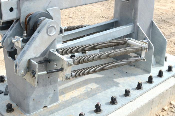
9 TECHNICAL DISCUSSION TEST PARAMETERS Test Facility The full-scale crash test reported herein was performed at Texas A&M Transportation Institute (TTI) Proving Ground. TTI Proving Ground is an International Standards Organization (ISO) accredited laboratory with American Association for Laboratory Accreditation (A2LA) Mechanical Testing certificate The full-scale crash test was performed according to TTI Proving Ground quality procedures developed for ISO accreditation and according to the ASTM F2656 guidelines and standards. The test facilities at the Texas A&M Transportation Institute s Proving Ground consist of a 2000-acre complex of research and training facilities situated 10 miles northwest of the main campus of Texas A&M University. The site, formerly an Air Force base, has large expanses of concrete runways and parking aprons well suited for experimental research and testing in the areas of vehicle performance and handling, vehicle-roadway interaction, durability and efficacy of highway pavements, and evaluation of roadside safety hardware and perimeter security devices. The site selected for installation of the RSS-3000 Drop Beam System was at the end of a wide out-of-service apron. The apron consists of an unreinforced jointed concrete pavement in 12.5 ft 15 ft blocks nominally 6 inches deep. The apron is over 50 years old and the joints have some displacement, but are otherwise flat and level. Test Article Design and Construction The test installation consisted of a RSSI M30 P1 Electric Drop Arm, a proprietary vehicle barrier system. The overall installed width of the system, including foundations, was 21 ft-7½ inches. The total roadway clearance was 10 ft-7½ inches, measured to the inside face of each of two foundations at either end of the installation. The bottom of the Drop Arm was 2 ft-9½ inches above the road surface. The drop arm was fabricated from 6-inch 3-inch ⅜-inch A36 rectangular tubing. The total length of the drop arm was 19 ft-9½ inches. The open span between the road-side faces of the support bollards was 12 ft-11½ inches. The drop arm was counterbalanced with eight tension springs (four each side) that were ganged and attached to two crank arms (one each side). The crank arms were connected to the drop arm via a 2 7 / 16 -inch diameter pivot pin, and the arms were fully welded on all sides. The pivot pin was supported by two 2 7 / 16 -inch Cooper P03 2-bolt pillow block bearings, one on each side of the drop arm. Impact arresting pegs, each 2-inch diameter, were located in each end of the drop arm at 3 inches beyond the field-side face of each support bollard, and, upon impact, engaged ½-inch thick beam guides in the top of each post. TR No RSS
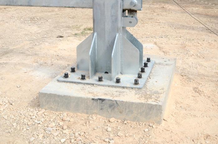
10 The pivot side support post was fabricated from 12-inch 12-inch ½-inch A36 rectangular tubing, and was 37½ inches tall. It was welded to a 71-inch 41-inch ¾-inch thick base plate of A36 material with twenty-eight 1¼-inch diameter anchor bolt holes. Two 8-inch 18-inch ½-inch thick vertical gussets were welded to both the up and down stream faces of the post, and two 4-inch 18-inch ½-inch thick vertical gussets were welded to the road side face of the post (for a total of 6 gussets) and to the base plate. A square bottomed V notch was fabricated in the top of the bollard to act as a beam guide/receiver for the drop arm. The pivot mechanism was supported by a similar A36 rectangular tubing 12-inch 12-inch ½-inch, which was 23 inches tall. Two 36-inch long 2-inch 3-inch ¼-inch angles connected the bollard to the support. The static side support post was fabricated from 12-inch 12-inch ½-inch A36 rectangular tubing, and was 37½ inches tall. It was welded to a 36-inch 36-inch ¾-inch thick base plate of A36 material with sixteen 1¼-inch diameter anchor bolt holes. Two 8-inch 16-inch ½-inch thick vertical gussets were welded to each of the bollard s four corners (for a total of 8 gussets) and to the base plate. Four 3-inch 30-inch ¾-inch thick internal vertical stiffeners were welded to bridge each internal corner of the static post. A square bottomed V notch was fabricated in the top of the bollard to act as a beam guide/receiver for the drop arm. All drop arm components were hot dip galvanized with the exception of the tension springs and the pillow block bearings. For this test, neither the electric drive lift mechanism system nor the decorative cowlings were installed. No area paving or simulated roadway was placed around or in between the foundations. The pivot side foundation was 7 ft wide 4 ft long 3 ft-6 inches deep (nominal dimensions) reinforced poured-in-place concrete. The top of the foundation was 6 inches above grade, thus leaving 3 ft buried in the soil. Reinforcement consisted of #5 rebar with a minimum of 3½ inches of concrete cover on the top and on the upstream and downstream faces, and approximately 11 inches on the roadside face and 8 inches on the field face. The 3-level rebar cage was approximately 5 ft-8½ inches wide 3 ft-6½ inches long 2 ft deep. Rebar spacing averaged approximately 13 inches with six 3 ft-6½ inch long bars and four 5 ft-9 inch long bars in each of three mats. Additionally, twenty-four 2 ft-½ inch long bars secured the three mats in the vertical direction at each node. The rebar cage was field tied. Once the concrete hardened, twenty-eight 1-inch diameter 16-inch long grade 4140 threaded rods were embedded 12 inches deep into site drilled 1⅛-inch diameter holes in the foundation and secured with MKT LiquidRoc 500 Epoxy per MKT instructions. Flat washers and double hex nuts were used to secure the pivot mechanism to the foundation. The foundation was back-filled and compacted with crushed limestone base material. The pivot side foundation weighed approximately 14,700 lb. The static side foundation was 4 ft wide 5 ft long 3 ft-6 inches deep (nominal dimensions) reinforced poured-in-place concrete. The top of the foundation was 6 inches above grade, thus leaving 3 ft buried in the soil. Reinforcement consisted of #5 rebar with a minimum TR No RSS
11 of 3½ inches of concrete cover on the top, and approximately 11 inches on the upstream and downstream faces, 9½ inches on the roadside face, and 10½ inches on the field face. The 3-level rebar cage was approximately 2 ft-5 inches wide 3 ft-3½ inches long 2 ft-½ inch deep. Rebar spacing averaged approximately 13 inches width wise and 7½ inches length wise, with three 3 ft-3½ inch long bars and six 2 ft-5 inch long bars in each of three mats. Additionally, eighteen 2 ft-½ inch long bars secured the three mats in the vertical direction at each node. The rebar cage was field tied. Sixteen 1-inch diameter 16-inch long grade 4140 threaded rods were embedded 12 inches deep in the foundation and secured with 3-inch square ⅜-inch thick flat washers and nuts. A pre-drilled plywood template located and temporarily secured the bolts in the foundation form. Flat washers and double hex nuts were used to secure the pivot mechanism to the foundation. The foundation was back-filled and compacted with crushed limestone base material. The static side foundation weighed approximately 10,500 lb. At the time of the crash test, the average moisture content of the crushed limestone base material in which the RSSI Electric Drop Arm foundations were installed was 5.0 percent and average compaction was 91.8 percent. Concrete strength for the drop arm installation was specified to be 5000 psi minimum. The foundations were poured on September 5, 2013, and had a reported average strength of 4790 psi on the test date of September 10, All steel reinforcing bar material was specified as grade 60. Overall details of the test installation are provided in Figure 1 and Figure 2. Further details can be found in Appendix A. Metal fabrication drawings are on file at the TTI Proving Ground. Test Conditions and Evaluation Criteria The test reported herein was performed in accordance with ASTM F Appendix B presents a brief description of the procedures followed for this test. According to ASTM F , the RSS-3000 Drop Beam System can be rated according to one of three designated condition levels when tested with a medium-duty truck, as shown in Table 1. The levels of kinetic energy that a security device shall withstand at each condition level are also shown in Table 1. The test conditions are intended to ensure that perimeter barriers and gates will provide a specified level of vehicle impact resistance. Actual vehicle weight and speed must be within a permissible range to receive the specific condition designation. The condition designations, which are defined by test vehicle type and impact speed, are shown in the last column of Table 1 as taken from ASTM F TR No RSS
12 TR No RSS Figure 1. Details of the RSS-3000 Drop Beam System.


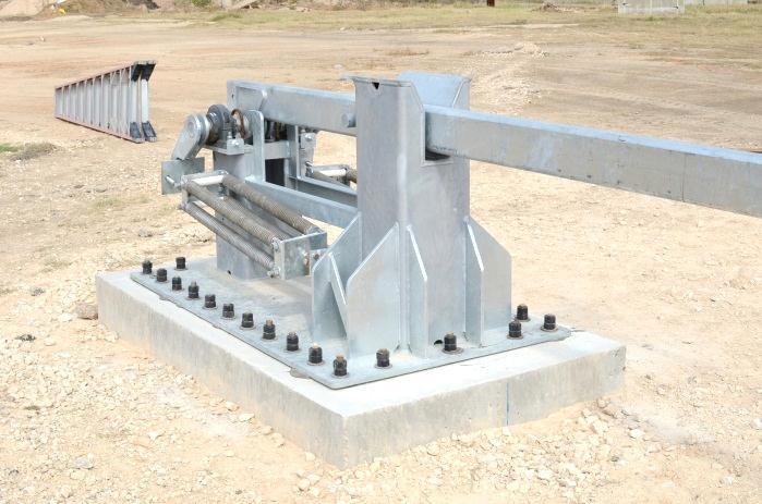
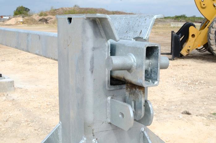
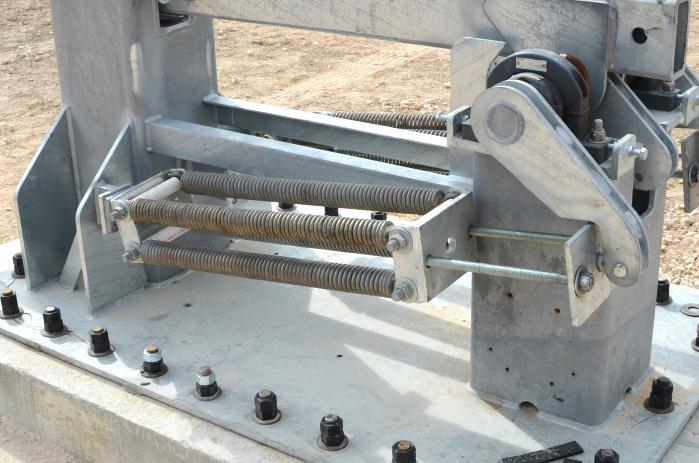
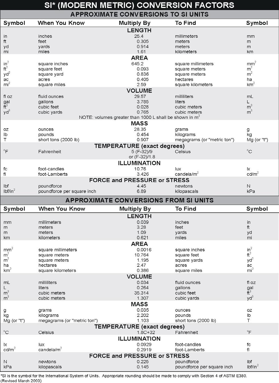
13 Figure 2. RSS-3000 Drop Beam System prior to testing. TR No RSS
14 Table 1. Impact Condition Designations according to ASTM F Test Vehicle/Minimum Test Inertial Mass, kg(lbm) Small passenger car (C) 1100 (2430) Pickup truck (P) 2300 (5070) Medium-duty truck (M) 6800(15000) Heavy goods vehicle (H) 29500(65000) Nominal Minimum Test Velocity km/h(mph) 65 (40) 80 (50) 100 (60) 65 (40) 80 (50) 100 (60) 50 (30) 65 (40) 80 (50) 50 (30) 65 (40) 80 (50) Permissible Speed Range, km/h (mph) ( ) ( ) 90.1-above (57.0- above) ( ) ( ) 90.1-above (57.0- above) ( ) ( ) 75.1-above (47.0- above) ( ) ( ) 75.1-above (47.0- above) Kinetic Energy, KJ (ft-kips) 179 (131) 271 (205) 424 (295) 375 (273) 568 (426) 887 (613) 656 (451) 1110 (802) 1680 (1250) 2850 (1950) 4810 (3470) 7280 (5430) Condition Designation C40 C50 C60 PU40 PU50 PU60 M30 M40 M50 H30 H40 H50 The test vehicle specified was a medium duty truck with diesel engine, tested at a vehicle gross weight of 15,000 lb ±309 lb. According to Condition Designation M30 of ASTM F , which involves the medium duty truck impacting at mi/h, the RSS-3000 Drop Beam System is required to withstand kinetic energy of 451,000 ft-lb. The amount of vehicle penetration of the security device at the required impact velocity determines the dynamic penetration rating for each condition designation. Test vehicle dynamic penetration is referenced to each vehicle as follows: The base of the A pillar for the small passenger car (C); the front leading lower edge of the pickup truck bed (P); the leading lower edge of the cargo bed on the medium duty truck (M); and the leading lower vertical edge of the cargo bed on the heavy goods vehicle (H). Penetration ratings according to ASTM F are shown in table 2. Table 2. Penetration Ratings according to ASTM F Penetration Designation P1 P2 P3 P4 Dynamic Penetration Rating 1 m (3.3 ft) 1.01 m to 7 m (3.31 to 23.0 ft) 7.01 m to 30 m (23.1 to 98.4 ft) 30 m (98 ft) or greater TR No RSS
15 CRASH TEST RSS3 (ASTM F M30) Test Vehicle A 2000 International 4700 single-unit flatbed truck, shown in Figures 3 and 4, was used for the crash test. Test inertia weight of the vehicle was 15,100 lb. The height to the lower edge of the vehicle front bumper was 20.0 inches, and the height to the upper edge of the front bumper was 31.0 inches. Table 3 in Appendix C gives additional dimensions and information on the vehicle. The vehicle was directed into the installation using the cable reverse tow and guidance system, and was released to be free-wheeling and unrestrained just prior to impact. Weather Conditions The crash test was performed the morning of September 10, Weather conditions at the time of testing were: Wind Speed: 5 mi/h; Wind Direction: 105 degrees with respect to the vehicle (vehicle was traveling in a northerly direction); Temperature: 85ºF; Relative Humidity: 72 percent. Impact Description The 2000 International 4700 single-unit flatbed truck, traveling at an impact speed of 30.8 mi/h, impacted the RSS-3000 Drop Beam System at an impact angle of 90.2 degrees. The centerline of the vehicle was aligned with the centerline of the span between the drop arm pegs of the RSS-3000 Drop Beam System. At approximately s after impact, the hood of the vehicle began to ride up and over the drop arm, and at s, the hood detached from the vehicle. The front of the vehicle pitched downward at s as the vehicle travel forward, and the cab of the vehicle began to deform and the windshield separated from the cab at s. At s, the cab began to deform around the drop arm, and at s, the front of the vehicle began to pitch downward. The vehicle stopped forward motion at s, and then began to rebound at s. The vehicle did not penetrate the drop arm and subsequently came to rest with the leading edge of the cargo bed 46 inches forward of the protected edge of the installation. Appendix D, Figure 10 show sequential photographs of the test period. Damage to Test Article Damage to RSS-3000 Drop Beam System is shown in Figures 5 and 6. The foundation on the right side was pulled up from the ground 3 inches. The foundation on the left side was pushed toward the protected side ¼ inch. The drop arm was deformed upward and toward the protected side 17¼ inches. TR No RSS


16 Figure 3. Vehicle/installation geometrics for test no RSS3. TR No RSS


17 Figure 4. Vehicle before test no RSS3. TR No RSS


18 Figure 5. Vehicle trajectory path after test no RSS3. TR No RSS


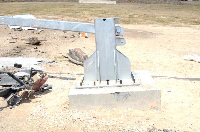
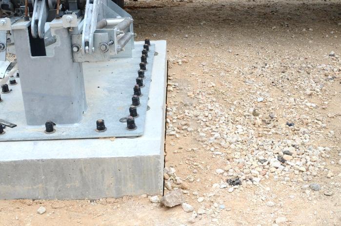
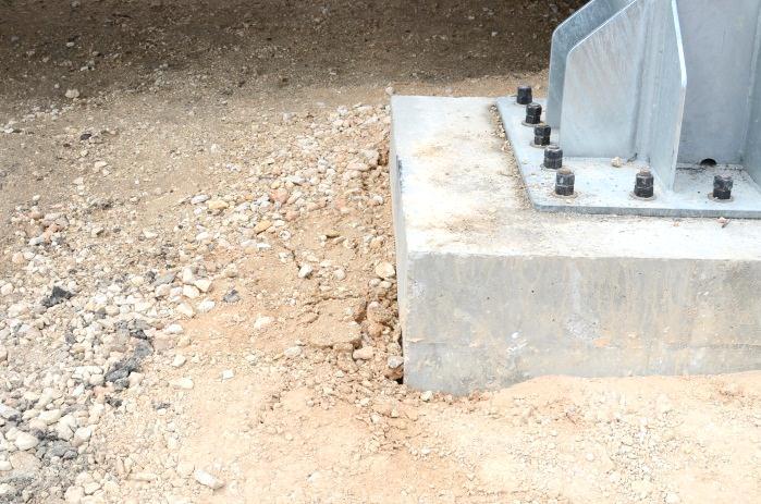
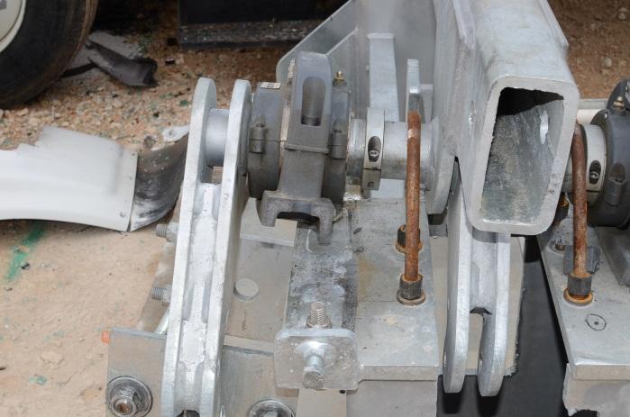
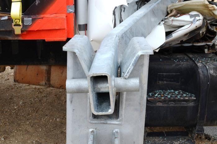
19 Figure 6. RSS-3000 Drop Beam System after test no RSS3. TR No RSS
20 Vehicle Damage Damage to the vehicle is shown in Figure 7. The transmission mount, drive shaft, motor mount, and steering column were deformed. Also damaged were the hood, radiator and support, fan, water pump, firewall, floor pan, cab, windshield, roof, right and left doors, instrument panel, and front seat. Estimated maximum exterior crush to the vehicle was 70 inches. Photographs of the interior of the vehicle are shown in Figure 8. Occupant Risk Factors Data from the accelerometer, located at the vehicle center of gravity, were digitized for evaluation of occupant risk for informational purposes only. In the longitudinal direction, the occupant impact velocity was 20.3 ft/s at s, the highest s occupant ridedown acceleration was 5.4 Gs from to s, and the maximum s average acceleration was -4.7 Gs between and s. In the lateral direction, the occupant impact velocity was 1.0 ft/s at s, the highest s occupant ridedown acceleration was 5.3 Gs from to s, and the maximum s average was -1.5 Gs between and s. These data and other pertinent information from the test are summarized in Figure 9. Vehicle accelerations versus time traces are presented in Appendix E, Figures 11 through 16. TR No RSS


21 Figure 7. Vehicle after test no RSS3. TR No RSS


22 BEFORE TEST AFTER TEST Figure 8. Interior of vehicle for test no RSS3. TR No RSS

23 TR No RSS s s s s General Information Test Agency... Texas A&M Transportation Institute (TTI) Test Standard Test No.... ASTM F M30 Test No RSS3 Date Test Article Type... Security Gate Name... RSS-3000 Drop Beam System Installation Length ft 7½ inches Material or Key Elements... Electric drop arm fabricated from HSS 6-inch 3-inch 3/8-inch with road clearance of 12 ft-11½ inches Soil/Foundation Type... Concrete foundation in crushed limestone Test Vehicle Type... Medium Duty Truck Designation... M30 Model International 4700 Mass Curb... 12,000 lb Test Inertial... 15,100 lb Impact Conditions Speed mi/h Angle degrees Exit Conditions Speed... Stopped Angle... NA Occupant Risk Values Impact Velocity Longitudinal ft/s Lateral ft/s Ridedown Accelerations Longitudinal G Lateral G Max s Average Longitudinal G Lateral G Vertical G Figure 9. Summary of results for ASTM F test M30 on RSS-3000 Drop Beam System. Distance Beyond Inside Edge of Security Device... Did not penetrate Truck Disabled?... Yes Rating... M30/P1
24
25 SUMMARY AND CONCLUSIONS ASSESSMENT OF TEST RESULTS The 2000 International 4700 single-unit flatbed truck impacted the security device at 90.2 degrees, with the centerline of the vehicle aligned with the centerline of the RSS-3000 Drop Beam System. The acceptable range for impact speed for this M30 test was at mi/h, and the actual impact speed was 30.8 mi/h. The RSS-3000 Drop Beam System brought the vehicle to a complete stop. The cargo remained onboard the vehicle; however, the hood and other parts of the vehicle were thrown beyond the protected edge of the security device. The vehicle was disabled. The leading edge of the cargo bed did not penetrate beyond the inside edge of the RSS-3000 Drop Beam System. CONCLUSIONS ASTM F provides a range of vehicle test designations and penetration levels that allow agencies to select perimeter security devices that satisfy their specific facility needs. The amount of vehicle penetration of the security device at the required impact velocity determines the dynamic penetration rating for each condition designation. The leading edge of the cargo bed did not penetrate beyond the inside edge of the RSS-3000 Drop Beam System. According to ASTM F , the RSS-3000 Drop Beam System meets Condition Designation/Penetration Rating M30/P1, which allows penetration of less than 3.3 ft when impacted by the medium duty truck at mi/h. TR No RSS
26
27 REFERENCES 1. Standard Test Method for Vehicle Crash Testing of Perimeter Barriers, ASTM Designation: F , American Standards for Testing Materials International, West Conshohocken, PA, August TR No RSS
28
29 APPENDIX A. DETAILS OF THE RSS-3000 DROP BEAM SYSTEM TR No RSS
30 TR No RSS
31 TR No RSS
32 TR No RSS
33 TR No RSS
34 TR No RSS
35 APPENDIX B. CRASH TEST PROCEDURES AND DATA ANALYSIS The crash test and data analysis procedures were in accordance with guidelines presented in ASTM F Brief descriptions of these procedures are presented as follows. ELECTRONIC INSTRUMENTATION AND DATA PROCESSING The test vehicle was instrumented with a self-contained, on-board data acquisition system. The signal conditioning and acquisition system is a 16-channel, Tiny Data Acquisition System (TDAS) Pro produced by Diversified Technical Systems, Inc. The accelerometers, which measure the x, y, and z axis of vehicle acceleration, are strain gauge type with linear millivolt output proportional to acceleration. Angular rate sensors, measuring vehicle roll, pitch, and yaw rates, are ultra-small, solid state units designed for crash test service. The TDAS Pro hardware and software conform to the latest SAE J211, Instrumentation for Impact Test. Each of the 16 channels is capable of providing precision amplification, scaling, and filtering based on transducer specifications and calibrations. During the test, data are recorded from each channel at a rate of 10,000 values per second with a resolution of one part in 65,536. Once data are recorded, internal batteries back these up inside the unit should the primary battery cable be severed. Initial contact of the pressure switch on the vehicle bumper provides a time zero mark and initiates the recording process. After each test, the data are downloaded from the TDAS Pro unit into a laptop computer at the test site. The Test Risk Assessment Program (TRAP) software then processes the raw data to produce detailed reports of the test results. Each of the TDAS Pro units is returned to the factory annually for complete recalibration. All accelerometers are calibrated annually according to SAE J by means of an ENDEVCO 2901, precision primary vibration standard. This device and its support instruments are returned to the factory annually for a National Institute of Standards Technology (NIST) traceable calibration. The subsystems of each data channel are also evaluated annually, using instruments with current NIST traceability, and the results are factored into the accuracy of the total data channel, per SAE J211. Calibrations and evaluations are also made any time data are suspect. Acceleration data is measured with an expanded uncertainty of ±1.7% at a confidence factor of 95 percent (k=2). TRAP uses the data from WinDigit to compute occupant/compartment impact velocities, time of occupant/compartment impact after vehicle impact, and the highest 10-millisecond (ms) average ridedown acceleration. In addition, maximum average accelerations over 50-ms intervals in each of the three directions are computed. For reporting purposes, the data from the vehicle-mounted accelerometers are filtered with a 60-Hz digital filter, and acceleration versus time curves for the longitudinal, lateral, and vertical directions are plotted using TRAP. TR No RSS
36 PHOTOGRAPHIC INSTRUMENTATION AND DATA PROCESSING Photographic coverage of the test included three high-speed cameras: one overhead with a field of view perpendicular to the ground and directly over the impact point; one placed behind the installation at an angle; and a third placed to have a field of view parallel to and aligned with the installation at the downstream end. A flashbulb activated by pressure-sensitive tape switches was positioned on the impacting vehicle to indicate the instant of contact with the installation and was visible from each camera. The films from these high-speed cameras were analyzed on a computer-linked motion analyzer to observe phenomena occurring during the collision and to obtain time-event, displacement, and angular data. A mini-dv and still cameras recorded and documented conditions of the test vehicle and installation before and after the test. TEST VEHICLE PROPULSION AND GUIDANCE The test vehicle was towed into the test installation using a steel cable guidance and reverse tow system. A steel cable for guiding the test vehicle was tensioned along the path, anchored at each end, and threaded through an attachment to the front wheel of the test vehicle. An additional steel cable was connected to the test vehicle, passed around a pulley near the impact point, through a pulley on the tow vehicle, and then anchored to the ground such that the tow vehicle moved away from the test site. A two-to-one speed ratio between the test and tow vehicle existed with this system. Just prior to impact with the installation, the test vehicle was released to be free-wheeling and unrestrained. The vehicle remained free-wheeling, i.e., no steering or braking inputs, until the vehicle cleared the immediate area of the test site. TR No RSS
37 APPENDIX C. TEST VEHICLE PROPERTIES AND INFORMATION Table 3. Vehicle properties for test no RSS3. DATE: TEST NO.: RSS3 VIN NO.: 1HTSCABN6YH YEAR: 2000 MAKE: International MODEL: 4700 TIRE SIZE: 295/75R22 ODOMETER: ACCELEROMETERS K P S N T PENETRATION REFERENCE POINT TEST INERTIAL C.G. J I A L H O B C D E F G GEOMETRY (inches) M1 R Q M2 A B C D E F G H I J K L N O P Q R S T D+E = Allowed Range for Wheelbase (D+E) = 208 ±20 inches; Allowable Flatbed Length = 18 ft ±24 inches; Allowable U-bolt Spacing = 3 ft ±8 inches MASS DISTRIBUTION (lb) 3630 LF 3900 RF 3920 LR RR 3650 MASS (lb) CURB TEST INERTIAL M 1 M 2 M Total Allowed Range for Inertial Wt.= ± 309 lb TR No RSS
38


39 APPENDIX D. SEQUENTIAL PHOTOGRAPHS s s s s Figure 10. Sequential photographs for test no RSS3 (overhead and perpendicular views). TR No RSS

 (continued). TR No.")
40 0.488 s s s s Figure 10. Sequential photographs for test no RSS3 (overhead and perpendicular views) (continued). TR No RSS
41 TR No RSS Longitudinal Acceleration (G) X Acceleration at CG SAE Class 60 Filter 50-msec average Time (s) Test Number: RSS3 Test Standard Test No.: ASTM F M30 Test Article: RSS-3000 Drop Beam System Test Vehicle: 2000 International 4700 Truck Inertial Mass: 15,100 lb Impact Speed: 30.8 mph Impact Angle: 90.2 degrees Figure 11. Vehicle longitudinal accelerometer trace for test no RSS3 (accelerometer located at center of gravity). APPENDIX E. VEHICLE ACCELERATIONS
42 TR No RSS Lateral Acceleration (G) Y Acceleration at CG SAE Class 60 Filter 50-msec average Time (s) Figure 12. Vehicle lateral accelerometer trace for test no RSS3 (accelerometer located at center of gravity). Test Number: RSS3 Test Standard Test No.: ASTM F M30 Test Article: RSS-3000 Drop Beam System Test Vehicle: 2000 International 4700 Truck Inertial Mass: 15,100 lb Impact Speed: 30.8 mph Impact Angle: 90.2 degrees
43 TR No RSS Vertical Acceleration (G) Z Acceleration at CG SAE Class 60 Filter 50-msec average Time (s) Figure 13. Vehicle vertical accelerometer trace for test no RSS3 (accelerometer located at center of gravity). Test Number: RSS3 Test Standard Test No.: ASTM F M30 Test Article: RSS-3000 Drop Beam System Test Vehicle: 2000 International 4700 Truck Inertial Mass: 15,100 lb Impact Speed: 30.8 mph Impact Angle: 90.2 degrees
44 TR No RSS Longitudinal Acceleration (G) X Acceleration over rear axle SAE Class 60 Filter 50-msec average Time (s) Test Number: RSS3 Test Standard Test No.: ASTM F M30 Test Article: RSS-3000 Drop Beam System Test Vehicle: 2000 International 4700 Truck Inertial Mass: 15,100 lb Impact Speed: 30.8 mph Impact Angle: 90.2 degrees Figure 14. Vehicle longitudinal accelerometer trace for test no RSS3 (accelerometer located over rear axle).
45 TR No RSS Lateral Acceleration (G) Y Acceleration over rear axle SAE Class 60 Filter 50-msec average Time (s) Figure 15. Vehicle lateral accelerometer trace for test no RSS3 (accelerometer located over rear axle). Test Number: RSS3 Test Standard Test No.: ASTM F M30 Test Article: RSS-3000 Drop Beam System Test Vehicle: 2000 International 4700 Truck Inertial Mass: 15,100 lb Impact Speed: 30.8 mph Impact Angle: 90.2 degrees
46 TR No RSS Vertical Acceleration (G) Z Acceleration over rear axle SAE Class 60 Filter 50-msec average Time (s) Figure 16. Vehicle vertical accelerometer trace for test no RSS3 (accelerometer located over rear axle). Test Number: RSS3 Test Standard Test No.: ASTM F M30 Test Article: RSS-3000 Drop Beam System Test Vehicle: 2000 International 4700 Truck Inertial Mass: 15,100 lb Impact Speed: 30.8 mph Impact Angle: 90.2 degrees
CRASH TEST AND EVALUATION OF 3-FT MOUNTING HEIGHT SIGN SUPPORT SYSTEM
 TTI: 9-1002-15 CRASH TEST AND EVALUATION OF 3-FT MOUNTING HEIGHT SIGN SUPPORT SYSTEM ISO 17025 Laboratory Testing Certificate # 2821.01 Crash testing performed at: TTI Proving Ground 3100 SH 47, Building
MASH Test 3-11 on the T131RC Bridge Rail
 TTI: 9-1002-12 MASH Test 3-11 on the T131RC Bridge Rail ISO 17025 Laboratory Testing Certificate # 2821.01 Crash testing performed at: TTI Proving Ground 3100 SH 47, Building 7091 Bryan, TX 77807 Test
CRASH TESTING OF RSA/K&C ANTI-RAM FOUNDATION BOLLARD PAD IN ACCORDANCE WITH U.S. DEPARTMENT OF STATE DIPLOMATIC SECURITY SD-STD-02.
 CRASH TESTING OF RSA/K&C ANTI-RAM FOUNDATION BOLLARD PAD IN ACCORDANCE WITH U.S. DEPARTMENT OF STATE DIPLOMATIC SECURITY SD-STD-02.01 REVISION A Prepared for RSA Protective Technologies, LLC FINAL REPORT
CRASH TEST AND EVALUATION OF TEMPORARY WOOD SIGN SUPPORT SYSTEM FOR LARGE GUIDE SIGNS
 TTI: 9-1002-15 CRASH TEST AND EVALUATION OF TEMPORARY WOOD SIGN SUPPORT SYSTEM FOR LARGE GUIDE SIGNS ISO 17025 Laboratory Testing Certificate # 2821.01 Crash testing performed at: TTI Proving Ground 3100
FAAC International, Inc.
 TEST REPORT FOR: FAAC International, Inc. J 355 HA M30 (K4) Bollard TESTED TO: ASTM F 2656-07 Standard Test Method for Vehicle Crash Testing of Perimeter Barriers Test M30 PREPARED FOR: FAAC International,
MASH TEST 3-11 OF THE TxDOT T222 BRIDGE RAIL
 TTI: 9-1002-12 MASH TEST 3-11 OF THE TxDOT T222 BRIDGE RAIL ISO 17025 Laboratory Testing Certificate # 2821.01 Crash testing performed at: TTI Proving Ground 3100 SH 47, Building 7091 Bryan, TX 77807 Test
MASH08 TEST 3-11 OF THE ROCKINGHAM PRECAST CONCRETE BARRIER
 Proving Ground Report No. 400001-RPC4 Report Date: July 2009 MASH08 TEST 3-11 OF THE ROCKINGHAM PRECAST CONCRETE BARRIER by C. Eugene Buth, P.E. Research Engineer William F. Williams, P.E. Assistant Research
CRASH TEST REPORT FOR PERIMETER BARRIERS AND GATES TESTED TO SD-STD-02.01, REVISION A, MARCH Anti-Ram Bollards
 CRASH TEST REPORT FOR PERIMETER BARRIERS AND GATES TESTED TO SD-STD-02.01, REVISION A, MARCH 2003 Anti-Ram Bollards Prepared for: RSA Protective Technologies, LLC 1573 Mimosa Court Upland, CA 91784 Test
Form DOT F (8-72) Texas Transportation Institute The Texas A&M University System College Station, Texas
 Texas Transportation Institute The Texas A&M University System College Station, Texas") 1. Report No. FHWA/TX-02/4162-1 Technical Report Documentation Page 2. Government Accession No. 3. Recipient's Catalog No. 4. Title and Subtitle EVALUATION OF TEXAS GRID-SLOT PORTABLE CONCRETE BARRIER
1. Report No. FHWA/TX-02/4162-1 Technical Report Documentation Page 2. Government Accession No. 3. Recipient's Catalog No. 4. Title and Subtitle EVALUATION OF TEXAS GRID-SLOT PORTABLE CONCRETE BARRIER
MASH TEST 3-11 OF THE TxDOT SINGLE SLOPE BRIDGE RAIL (TYPE SSTR) ON PAN-FORMED BRIDGE DECK
 ON PAN-FORMED BRIDGE DECK") TTI: 9-1002 MASH TEST 3-11 OF THE TxDOT SINGLE SLOPE BRIDGE RAIL (TYPE SSTR) ON PAN-FORMED BRIDGE DECK ISO 17025 Laboratory Testing Certificate # 2821.01 Crash testing performed at: TTI Proving Ground
TTI: 9-1002 MASH TEST 3-11 OF THE TxDOT SINGLE SLOPE BRIDGE RAIL (TYPE SSTR) ON PAN-FORMED BRIDGE DECK ISO 17025 Laboratory Testing Certificate # 2821.01 Crash testing performed at: TTI Proving Ground
NCHRP Report 350 Crash Testing and Evaluation of the S-Square Mailbox System
 TTI: 0-5210 NCHRP Report 350 Crash Testing and Evaluation of the S-Square Mailbox System ISO 17025 Laboratory Testing Certificate # 2821.01 Crash testing performed at: TTI Proving Ground 3100 SH 47, Building
RSA Protective Technologies
 TEST REPORT FOR: RSA Protective Technologies K12 Surface Mounted Bollard System TESTED TO: ASTM F 2656-07 Standard Test Method for Vehicle Crash Testing of Perimeter Barriers Test M50 PREPARED FOR: Battelle
Texas Transportation Institute The Texas A&M University System College Station, Texas
 1. Report No. FHWA/TX-05/9-8132-P7 4. Title and Subtitle TL-4 CRASH TESTING OF THE F411 BRIDGE RAIL 2. Government Accession No. 3. Recipient's Catalog No. 5. Report Date October 2004 Technical Report Documentation
Virginia Department of Transportation
 TEST REPORT FOR: Virginia Department of Transportation SKT SP 350 50 (15.24 m) System PREPARED FOR: Virginia Department of Transportation 1401 E. Broad St. Richmond, VA 23219 TEST REPORT NUMBER: REPORT
A MASH Compliant W-Beam Median Guardrail System
 0 0 0 0 0 A MASH Compliant W-Beam Median Guardrail System By A. Y. Abu-Odeh, R. P. Bligh, W. Odell, A. Meza, and W. L. Menges Submitted: July 0, 0 Word Count:, + ( figures + tables=,000) =, words Authors:
MASH TEST 3-37 OF THE TxDOT 31-INCH W-BEAM DOWNSTREAM ANCHOR TERMINAL
 TTI: 9-1002 MASH TEST 3-37 OF THE TxDOT 31-INCH W-BEAM DOWNSTREAM ANCHOR TERMINAL ISO 17025 Laboratory Testing Certificate # 2821.01 Crash testing performed at: TTI Proving Ground 3100 SH 47, Building
DEVELOPMENT OF A MASH TL-3 MEDIAN BARRIER GATE
 TTI: 9-1002 DEVELOPMENT OF A MASH TL-3 MEDIAN BARRIER GATE ISO 17025 Laboratory Testing Certificate # 2821.01 Crash testing performed at: TTI Proving Ground 3100 SH 47, Building 7091 Bryan, TX 77807 Research/Test
OPTIMIZATION OF THRIE BEAM TERMINAL END SHOE CONNECTION
 TTI: 9-1002-15 OPTIMIZATION OF THRIE BEAM TERMINAL END SHOE CONNECTION ISO 17025 Laboratory Testing Certificate # 2821.01 Pendulum testing performed at: TTI Proving Ground 3100 SH 47, Building 7091 Bryan,
MASH TEST 3-10 ON 31-INCH W-BEAM GUARDRAIL WITH STANDARD OFFSET BLOCKS
 TTI: 9-1002 MASH TEST 3-10 ON 31-INCH W-BEAM GUARDRAIL WITH STANDARD OFFSET BLOCKS ISO 17025 Laboratory Testing Certificate # 2821.01 Crash testing performed at: TTI Proving Ground 3100 SH 47, Building
NCHRP Report 350 Test 4-12 of the Modified Thrie Beam Guardrail
 NCHRP Report 350 Test 4-12 of the Modified Thrie Beam Guardrail PUBLICATION NO. FHWA-RD-99-065 DECEMBER 1999 Research, Development, and Technology Turner-Fairbank Highway Research Center 6300 Georgetown
TEXAS TRANSPORTATION INSTITUTE THE TEXAS A & M UNIVERSITY SYSTEM COLLEGE STATION, TEXAS 77843
 NCHRP REPORT 350 ASSESSMENT OF EXISTING ROADSIDE SAFETY HARDWARE by C. Eugene Buth, P.E. Senior Research Engineer Wanda L. Menges Associate Research Specialist and Sandra K. Schoeneman Research Associate
REPORT NUMBER: 301-MGA SAFETY COMPLIANCE TESTING FOR FMVSS 301R FUEL SYSTEM INTEGRITY REAR IMPACT
 REPORT NUMBER: 301-MGA-2010-007 SAFETY COMPLIANCE TESTING FOR FMVSS 301R FUEL SYSTEM INTEGRITY REAR IMPACT NISSAN MOTOR COMPANY LTD 2010 NISSAN CUBE NHTSA NUMBER: CA5205 PREPARED BY: MGA RESEARCH CORPORATION
REPORT NUMBER: 301-CAL SAFETY COMPLIANCE TESTING FOR FMVSS 301 FUEL SYSTEM INTEGRITY HONDA MOTOR COMPANY 2007 HONDA ACCORD 4-DOOR SEDAN
 REPORT NUMBER: 301-CAL-07-05 SAFETY COMPLIANCE TESTING FOR FMVSS 301 FUEL SYSTEM INTEGRITY HONDA MOTOR COMPANY 2007 HONDA ACCORD 4-DOOR SEDAN NHTSA NUMBER: C75304 CALSPAN TEST NUMBER: 8832-F301-05 CALSPAN
STI Project: Barrier Systems, Inc. RTS-QMB Longitudinal Barrier. Page 38 of 40 QBOR1. Appendix F (Continued) Figure F-3
 Figure F-3") Barrier Systems, Inc. RTS-QMB Longitudinal Barrier STI Project: QBOR1 Page 38 of 40 Appendix F (Continued) Figure F-3 t=.500sec 115 meters overall 37.1 Impact Severity (kj).. 141.6 Angle (deg).. 25 Speed
Barrier Systems, Inc. RTS-QMB Longitudinal Barrier STI Project: QBOR1 Page 38 of 40 Appendix F (Continued) Figure F-3 t=.500sec 115 meters overall 37.1 Impact Severity (kj).. 141.6 Angle (deg).. 25 Speed
Evaluation of Barriers for Very High Speed Roadways
 TTI: 0-6071 Evaluation of Barriers for Very High Speed Roadways ISO 17025 Laboratory Testing Certificate # 2821.01 Crash testing performed at: TTI Proving Ground 3100 SH 47, Building 7091 Bryan, TX 77807
REPORT NUMBER: 301-MGA SAFETY COMPLIANCE TESTING FOR FMVSS 301R FUEL SYSTEM INTEGRITY REAR IMPACT
 REPORT NUMBER: 301-MGA-2011-008 SAFETY COMPLIANCE TESTING FOR FMVSS 301R FUEL SYSTEM INTEGRITY REAR IMPACT MAZDA MOTOR CORPORATION 2011 MAZDA 2 SPORT MT NHTSA NUMBER: CB5400 PREPARED BY: MGA RESEARCH CORPORATION
GUARDRAIL TESTING MODIFIED ECCENTRIC LOADER TERMINAL (MELT) AT NCHRP 350 TL-2. Dean C. Alberson, Wanda L. Menges, and Rebecca R.
 AT NCHRP 350 TL-2. Dean C. Alberson, Wanda L. Menges, and Rebecca R.") GUARDRAIL TESTING MODIFIED ECCENTRIC LOADER TERMINAL (MELT) AT NCHRP 350 TL-2 Dean C. Alberson, Wanda L. Menges, and Rebecca R. Haug Prepared for The New England Transportation Consortium July 2002 NETCR
GUARDRAIL TESTING MODIFIED ECCENTRIC LOADER TERMINAL (MELT) AT NCHRP 350 TL-2 Dean C. Alberson, Wanda L. Menges, and Rebecca R. Haug Prepared for The New England Transportation Consortium July 2002 NETCR
Texas Transportation Institute The Texas A&M University System College Station, Texas
 1. Report No. FHWA/TX-04/9-8132-1 4. Title and Subtitle TESTING AND EVALUATION OF THE FLORIDA JERSEY SAFETY SHAPED BRIDGE RAIL 2. Government Accession No. 3. Recipient's Catalog No. 5. Report Date February
Manual for Assessing Safety Hardware
 American Association of State Highway and Transportation Officials Manual for Assessing Safety Hardware 2009 vii PREFACE Effective traffic barrier systems, end treatments, crash cushions, breakaway devices,
Sponsored by Roadside Safety Research Program Pooled Fund Study No. TPF-5(114)
") Proving Ground Test Report No. 405160-23-2 Test Report Date: February 2012 MASH TEST 3-11 OF THE W-BEAM GUARDRAIL ON LOW-FILL BOX CULVERT by William F. Williams, P.E. Associate Research Engineer and Wanda
Proving Ground Test Report No. 405160-23-2 Test Report Date: February 2012 MASH TEST 3-11 OF THE W-BEAM GUARDRAIL ON LOW-FILL BOX CULVERT by William F. Williams, P.E. Associate Research Engineer and Wanda
REPORT NUMBER: 301-MGA SAFETY COMPLIANCE TESTING FOR FMVSS 301R FUEL SYSTEM INTEGRITY REAR IMPACT
 REPORT NUMBER: 301-MGA-2010-005 SAFETY COMPLIANCE TESTING FOR FMVSS 301R FUEL SYSTEM INTEGRITY REAR IMPACT NISSAN MOTOR COMPANY LTD 2010 NISSAN CUBE NHTSA NUMBER: CA5201 PREPARED BY: MGA RESEARCH CORPORATION
Texas Transportation Institute The Texas A&M University System College Station, Texas
 1. Report No. FHWA/TX-07/0-5527-1 4. Title and Subtitle DEVELOPMENT OF A LOW-PROFILE TO F-SHAPE TRANSITION BARRIER SEGMENT 2. Government Accession No. 3. Recipient's Catalog No. Technical Report Documentation
TEXAS TRANSPORTATION INSTITUTE THE TEXAS A & M UNIVERSITY SYSTEM COLLEGE STATION, TEXAS 77843
 NCHRP REPORT 350 TEST 3-11 OF THE NEW YORK DOT PORTABLE CONCRETE BARRIER WITH I-BEAM CONNECTION (RETEST) by Roger P. Bligh, P.E. Assistant Research Engineer Wanda L. Menges Associate Research Specialist
MASH TEST 3-21 ON TL-3 THRIE BEAM TRANSITION WITHOUT CURB
 TTI: 9-1002-12 MASH TEST 3-21 ON TL-3 THRIE BEAM TRANSITION WITHOUT CURB ISO 17025 Laboratory Testing Certificate # 2821.01 Crash testing performed at: TTI Proving Ground 3100 SH 47, Building 7091 Bryan,
Remote Combination Adaptive Driving Equipment Investigation Dynamic Science, Inc. (DSI), Case Number G 1990 Ford Bronco Arizona October
, Case Number G 1990 Ford Bronco Arizona October") Remote Combination Adaptive Driving Equipment Investigation Dynamic Science, Inc. (DSI), Case Number 2007-76-131G 1990 Ford Bronco Arizona October 2007 This document is disseminated under the sponsorship
Remote Combination Adaptive Driving Equipment Investigation Dynamic Science, Inc. (DSI), Case Number 2007-76-131G 1990 Ford Bronco Arizona October 2007 This document is disseminated under the sponsorship
CRASH TEST OF MILE POST MARKER. T. J. Hirsch Research Engineer. and. Eugene Buth Assistant Research Engineer. Research Report Number 146-8
 CRASH TEST OF MILE POST MARKER by T. J. Hirsch Research Engineer and Eugene Buth Assistant Research Engineer Research Report Number 146-8 Studies of Field Adaption of Impact Attenuation Systems Research
REPORT NUMBER: 301-MGA SAFETY COMPLIANCE TESTING FOR FMVSS 301R FUEL SYSTEM INTEGRITY REAR IMPACT
 REPORT NUMBER: 301-MGA-2007-002 SAFETY COMPLIANCE TESTING FOR FMVSS 301R FUEL SYSTEM INTEGRITY REAR IMPACT NISSAN MOTOR CO., LTD. 2006 NISSAN PATHFINDER LE 4X2 NHTSA NUMBER: C65200 PREPARED BY: MGA RESEARCH
I. 22. Price. Technical Report Documentation Page
 1. Report No. TX-00/1914-5 1 2. Government Accession No. 4. Title and Subtitle THE 1995 PERFORMANCE RESULTS FOR SLOPE PROTECTION PRODUCTS, HYDRAULIC MULCHES, AND FLEXIBLE CHANNEL LINERS Technical Report
Texas Transportation Institute The Texas A&M University System College Station, Texas
 2. Government Accession No. 3. Recipient's Catalog No. 1. Report No. FHWA/TX-03/0-4138-3 4. Title and Subtitle PERFORMANCE OF THE TXDOT T202 (MOD) BRIDGE RAIL REINFORCED WITH FIBER REINFORCED POLYMER BARS
REPORT NUMBER: 301-CAL SAFETY COMPLIANCE TESTING FOR FMVSS 301 FUEL SYSTEM INTEGRITY REAR IMPACT FORD MOTOR COMPANY 2009 FORD F150 2-DOOR PICKUP
 REPORT NUMBER: 301-CAL-09-03 SAFETY COMPLIANCE TESTING FOR FMVSS 301 FUEL SYSTEM INTEGRITY REAR IMPACT FORD MOTOR COMPANY 2009 FORD F150 2-DOOR PICKUP NHTSA NUMBER: C90206 CALSPAN TRANSPORTATION SCIENCES
REPORT NUMBER: 305-MGA
 REPORT NUMBER: 305-MGA-2011-004 SAFETY COMPLIANCE TESTING FOR FMVSS 305 Electric Powered Vehicles: Electrolyte Spillage and Electrical Shock Protection NISSAN MOTOR CO., LTD. 2011 NISSAN LEAF 5-DR HATCHBACK
REPORT NO. TR-P NC SAFETY COMPLIANCE TESTING FOR FMVSS 223 REAR IMPACT GUARDS 2007 TRANSFREIGHT TECHNOLOGY NHTSA NO.
 REPORT NO. SAFETY COMPLIANCE TESTING FOR FMVSS 223 REAR IMPACT GUARDS 2007 TRANSFREIGHT TECHNOLOGY NHTSA NO. RIG 009 PREPARED BY: KARCO ENGINEERING, LLC. 9270 HOLLY ROAD ADELANTO, CALIFORNIA 92301 SEPTEMBER
SAFETY COMPLIANCE TESTING FOR FMVSS NO. 214S SIDE IMPACT PROTECTION (STATIC)
") REPORT NUMBER 214-GTL-09-002 SAFETY COMPLIANCE TESTING FOR S SIDE IMPACT PROTECTION (STATIC) MAZDA MOTOR CORPORATION 2009 MAZDA 3, PASSENGER CAR NHTSA NO. C95400 GENERAL TESTING LABORATORIES, INC. 1623
REPORT NUMBER 214-GTL-09-002 SAFETY COMPLIANCE TESTING FOR S SIDE IMPACT PROTECTION (STATIC) MAZDA MOTOR CORPORATION 2009 MAZDA 3, PASSENGER CAR NHTSA NO. C95400 GENERAL TESTING LABORATORIES, INC. 1623
REPORT NUMBER: 301-CAL SAFETY COMPLIANCE TESTING FOR FMVSS 301 FUEL SYSTEM INTEGRITY REAR IMPACT MAZDA MOTOR CORPORATION 2008 MAZDA CX-9 SUV
 REPORT NUMBER: 301-CAL-08-03 SAFETY COMPLIANCE TESTING FOR FMVSS 301 FUEL SYSTEM INTEGRITY REAR IMPACT MAZDA MOTOR CORPORATION 2008 MAZDA CX-9 SUV NHTSA NUMBER: C85401 CALSPAN TRANSPORTATION SCIENCES CENTER
TEXAS TRANSPORTATION INSTITUTE THE TEXAS A & M UNIVERSITY SYSTEM COLLEGE STATION, TEXAS 77843
 NCHRP REPORT 350 TEST 3-11 OF THE STEEL-BACKED TIMBER GUARDRAIL by D. Lance Bullard, Jr., P.E. Associate Research Engineer Wanda L. Menges Associate Research Specialist and Sandra K. Schoeneman Research
Development of Turning Templates for Various Design Vehicles
 Transportation Kentucky Transportation Center Research Report University of Kentucky Year 1991 Development of Turning Templates for Various Design Vehicles Kenneth R. Agent Jerry G. Pigman University of
REPORT NUMBER: 301-CAL SAFETY COMPLIANCE TESTING FOR FMVSS 301 FUEL SYSTEM INTEGRITY REAR IMPACT
 REPORT NUMBER: 301-CAL-09-01 SAFETY COMPLIANCE TESTING FOR FMVSS 301 FUEL SYSTEM INTEGRITY REAR IMPACT HYUNDAI MOTOR COMPANY 2009 HYUNDAI ACCENT 4-DOOR SEDAN NHTSA NUMBER: C90503 CALSPAN TRANSPORTATION
REPORT NUMBER: 305-MGA
 REPORT NUMBER: 305-MGA-2011-001 SAFETY COMPLIANCE TESTING FOR FMVSS 305 Electric Powered Vehicles: Electrolyte Spillage and Electrical Shock Protection HONDA MOTOR CO., LTD 2011 HONDA CR-Z 3-DR HATCHBACK
VERIFICATION & VALIDATION REPORT of MGS Barrier Impact with 1100C Vehicle Using Toyota Yaris Coarse FE Model
 VERIFICATION & VALIDATION REPORT of MGS Barrier Impact with 1100C Vehicle Using Toyota Yaris Coarse FE Model CCSA VALIDATION/VERIFICATION REPORT Page 1 of 4 Project: CCSA Longitudinal Barriers on Curved,
TEXAS TRANSPORTATION INSTITUTE THE TEXAS A & M UNIVERSITY SYSTEM COLLEGE STATION, TEXAS
 NCHRP REPORT 350 TEST 4-21 OF THE ALASKA MULTI-STATE BRIDGE RAIL THRIE-BEAM TRANSITION by C. Eugene Buth Senior Research Engineer William F. Williams Assistant Research Engineer Wanda L. Menges Associate
July 10, Refer to: HSA-10/CC-78A
 July 10, 2003 Refer to: HSA-10/CC-78A Barry D. Stephens, P.E. Senior Vice President of Engineering ENERGY ABSORPTION Systems, Inc. 3617 Cincinnati Avenue Rocklin, California 95765 Dear Mr. Stephens: Your
February 8, In Reply Refer To: HSSD/CC-104
 February 8, 2008 200 New Jersey Avenue, SE. Washington, DC 20590 In Reply Refer To: HSSD/CC-04 Barry D. Stephens, P.E. Sr. Vice President Engineering Energy Absorption Systems, Inc. 367 Cincinnati Avenue
Product Specification. ABSORB 350 TM TL-2 Non-Redirective, Gating, Crash Cushion Applied to Quickchange Moveable Barrier
 TB 000612 Rev. 0 Page 1 of 9 Product Specification ABSORB 350 TM TL-2 Non-Redirective, Gating, Crash Cushion Applied to Quickchange Moveable Barrier I. General The ABSORB 350 TM TL-2 System is a Non-Redirective,
Universal TAU-IIR Redirective, Non-Gating, Crash Cushion
 TB 110927 Rev. 0 Page 1 of 5 Product Specification Universal TAU-IIR Redirective, Non-Gating, Crash Cushion I. General The Universal TAU-IIR system is a Redirective, Non-Gating Crash Cushion in accordance
COMPLIANCE TESTING FOR FMVSS 207 SEATING SYSTEMS
 REPORT NO. COMPLIANCE TESTING FOR FMVSS 207 SEATING SYSTEMS 2008 CHEVROLET IMPALA 4-DOOR NHTSA NO.C80102 PREPARED BY: KARCO ENGINEERING, LLC 9270 HOLLY ROAD ADELANTO, CALIFORNIA 92301 September 24, 2008
SAFETY COMPLIANCE TESTING FOR FMVSS 110 TIRE SELECTION AND RIMS
 REPORT NUMBER 110-STF-09-001 SAFETY COMPLIANCE TESTING FOR TIRE SELECTION AND RIMS GENERAL MOTORS CORPORATION 2009 CHEVROLET IMPALA FOUR-DOOR PASSENGER CAR NHTSA NO. C90100 U.S. DOT SAN ANGELO TEST FACILITY
REPORT NUMBER: NCAP305I-MGA NEW CAR ASSESSMENT PROGRAM (NCAP) FMVSS No. 305 Indicant Test
 FMVSS No. 305 Indicant Test") REPORT NUMBER: NCAP305I-MGA-2012-008 NEW CAR ASSESSMENT PROGRAM (NCAP) FMVSS No. 305 Indicant Test GENERAL MOTORS LLC 2013 Chevrolet Malibu ECO4-Dr Hybrid Sedan NHTSA NUMBER: MD0101 MGA RESEARCH CORPORATION
REPORT NUMBER: NCAP305I-MGA-2012-008 NEW CAR ASSESSMENT PROGRAM (NCAP) FMVSS No. 305 Indicant Test GENERAL MOTORS LLC 2013 Chevrolet Malibu ECO4-Dr Hybrid Sedan NHTSA NUMBER: MD0101 MGA RESEARCH CORPORATION
June 5, In Reply Refer To: HSSD/B-178. Mr. Kevin K. Groeneweg Mobile Barriers LLC Genesee Trail Road Golden, CO Dear Mr.
 June 5, 2008 1200 New Jersey Avenue, SE. Washington, DC 20590 In Reply Refer To: HSSD/B-178 Mr. Kevin K. Groeneweg Mobile Barriers LLC 24918 Genesee Trail Road Golden, CO 80401 Dear Mr. Groeneweg: This
GENERAL TESTING LABORATORIES, INC LEEDSTOWN ROAD COLONIAL BEACH, VIRGINIA 22443
 REPORT NUMBER 202a-GTL-10-004 SAFETY COMPLIANCE TESTING FOR S HEAD RESTRAINTS STATIC REQUIREMENTS VOLVO CAR CORPORATION 2010 VOLVO S40, PASSENGER CAR NHTSA NO. CA5900 GENERAL TESTING LABORATORIES, INC.
SAFETY COMPLIANCE TESTING FOR FMVSS 202a Head Restraints
 FINAL REPORT NUMBER 202a-MGA-10-003 SAFETY COMPLIANCE TESTING FOR FMVSS 202a FORD MOTOR COMPANY 2010 Lincoln MKT MPV NHTSA No. CA0213 MGA RESEARCH CORPORATION 446 Executive Drive Troy, Michigan 48083 Test
StopGate TM Barrier Arm GENERAL SPECIFICATIONS
 StopGate TM Barrier Arm GENERAL SPECIFICATIONS I. GENERAL All StopGate Barrier Arms shall be designed and manufactured by Energy Absorption Systems, Inc., of Chicago, Illinois. II. DESCRIPTION OF SYSTEM
REPORT NUMBER: 114-CAL SAFETY COMPLIANCE TESTING FOR FMVSS No. 114 THEFT PROTECTION AND ROLLOWAY PREVENTION
 REPORT NUMBER: 114-CAL-08-06 SAFETY COMPLIANCE TESTING FOR FMVSS No. 114 THEFT PROTECTION AND ROLLOWAY PREVENTION FORD MOTOR COMPANY 2008 FORD RANGER REGULAR CAB PICKUP NHTSA NUMBER: C80205 CALSPAN TEST
VULCAN BARRIER TL-3 GENERAL SPECIFICATIONS
 VULCAN BARRIER TL-3 GENERAL SPECIFICATIONS I. GENERAL A. The VULCAN BARRIER TL-3 (VULCAN TL-3) shall be a highly portable and crashworthy longitudinal barrier especially suited for use as a temporary barrier
SAFETY COMPLIANCE TESTING FOR FMVSS 225 Child Restraint Anchorage Systems
 FINAL REPORT NUMBER 225-MGA-06-002 SAFETY COMPLIANCE TESTING FOR FMVSS 225 GENERAL MOTORS CORPORATION 2006 HUMMER H3 NHTSA No. C60102 MGA RESEARCH CORPORATION 446 Executive Drive Troy, Michigan 48083 Test
ROBUST PROJECT Norwegian Public Roads Administration / Force Technology Norway AS
 ROBUST PROJECT Norwegian Public Roads Administration / Force Technology Norway AS Evaluation of small car - RM_R1 - prepared by Politecnico di Milano Volume 1 of 1 January 2006 Doc. No.: ROBUST-5-002/TR-2004-0039
MASH 2016 Implementation: What, When and Why
 MASH 2016 Implementation: What, When and Why Roger P. Bligh, Ph.D., P.E. Senior Research Engineer Texas A&M Transportation Institute June 7, 2016 2016 Traffic Safety Conference College Station, Texas Outline
Advances in Simulating Corrugated Beam Barriers under Vehicular Impact
 13 th International LS-DYNA Users Conference Session: Automotive Advances in Simulating Corrugated Beam Barriers under Vehicular Impact Akram Abu-Odeh Texas A&M Transportation Institute Abstract W-beam
SAFETY COMPLIANCE TESTING FOR FMVSS 225 Child Restraint Anchorage Systems
 FINAL REPORT NUMBER 225-MGA-06-007 SAFETY COMPLIANCE TESTING FOR FMVSS 225 TOYOTA MOTOR CORPORATION 2006 TOYOTA HIGHLANDER NHTSA No. C65101 MGA RESEARCH CORPORATION 446 Executive Drive Troy, Michigan 48083
REPORT NUMBER: 111SB-MGA SAFETY COMPLIANCE TESTING FOR FMVSS NO. 111SB SCHOOL BUS REARVIEW MIRRORS
 REPORT NUMBER: 111SB-MGA-2009-001 SAFETY COMPLIANCE TESTING FOR FMVSS NO. 111SB SCHOOL BUS REARVIEW MIRRORS THOMAS BUILT BUSES 2009 THOMAS MINOTOUR SCHOOL BUS NHTSA NO.: C90901 PREPARED BY: MGA RESEARCH
BarrierGate. General Specifications. Manual Operations General Specifications
 BarrierGate General Specifications Manual Operations General Specifications BarrierGate GENERAL SPECIFICATIONS I. GENERAL A. The BarrierGate system (the gate) shall be designed and manufactured by Energy
PR V2. Submitted by. Professor MIDWEST Vine Street (402) Submitted to
 Submitted to") FINAL REPORT PR4893118-V2 ZONE OF INTRUSION STUDY Submitted by John D. Reid, Ph.D. Professor Dean L.. Sicking, Ph.D., P.E. Professorr and MwRSF Director MIDWEST ROADSIDE SAFETY FACILITY University of Nebraska-Lincoln
FINAL REPORT PR4893118-V2 ZONE OF INTRUSION STUDY Submitted by John D. Reid, Ph.D. Professor Dean L.. Sicking, Ph.D., P.E. Professorr and MwRSF Director MIDWEST ROADSIDE SAFETY FACILITY University of Nebraska-Lincoln
Technical Report Documentation Page Form DOT F (8-72) Reproduction of completed page authorized
 Reproduction of completed page authorized") 1. Report No. FHWA/TX-05/0-4162-3 4. Title and Subtitle 2. Government Accession No. 3. Recipient's Catalog No. DEVELOPMENT OF LOW-DEFLECTION PRECAST CONCRETE ARRIER 5. Report Date January 2005 Technical
1. Report No. FHWA/TX-05/0-4162-3 4. Title and Subtitle 2. Government Accession No. 3. Recipient's Catalog No. DEVELOPMENT OF LOW-DEFLECTION PRECAST CONCRETE ARRIER 5. Report Date January 2005 Technical
Pedestrian Autonomous Emergency Braking Test Protocol (Version II) February 2019
 February 2019") Pedestrian Autonomous Emergency Braking Test Protocol (Version II) February 2019 Contents DOCUMENT REVISION HISTORY... ii SUMMARY... 1 TEST ENVIRONMENT... 2 Surface and Markings... 2 Surroundings... 2
Pedestrian Autonomous Emergency Braking Test Protocol (Version II) February 2019 Contents DOCUMENT REVISION HISTORY... ii SUMMARY... 1 TEST ENVIRONMENT... 2 Surface and Markings... 2 Surroundings... 2
SAFETY COMPLIANCE TESTING FOR FMVSS 110 TIRE SELECTION AND RIMS
 REPORT NUMBER 110-STF-10-004 SAFETY COMPLIANCE TESTING FOR FMVSS 110 TIRE SELECTION AND RIMS MAZDA MOTOR CORPORATION 2010 MAZDA 6 FOUR-DOOR PASSENGER CAR NHTSA NO. CA5402 U.S. DOT SAN ANGELO TEST FACILITY
SAFETY COMPLIANCE TESTING FOR FMVSS 124 ACCELERATOR CONTROL SYSTEMS
 REPORT NUMBER 124-GTL-07-001 SAFETY COMPLIANCE TESTING FOR FMVSS 124 ACCELERATOR CONTROL SYSTEMS HYUNDAI MOTOR COMPANY 2007 HYUNDAI ELANTRA 4-DOOR PASSENGER CAR NHTSA NO. C70502 GENERAL TESTING LABORATORIES,
November 16, 1998 Refer to: HNG-14. Mr. David Allardyce Mechanical Engineer B&B Electromatic Main Street Norwood, Louisiana 70761
 November 16, 1998 Refer to: HNG-14 Mr. David Allardyce Mechanical Engineer B&B Electromatic 14113 Main Street Norwood, Louisiana 70761 Dear Mr. Allardyce: In your August 31 letter, you presented some preliminary
1962: HRCS Circular 482 one-page document, specified vehicle mass, impact speed, and approach angle for crash tests.
 1 2 3 1962: HRCS Circular 482 one-page document, specified vehicle mass, impact speed, and approach angle for crash tests. 1973: NCHRP Report 153 16-page document, based on technical input from 70+ individuals
SAFETY COMPLIANCE TESTING FOR FMVSS NO. 401 INTERIOR TRUNK RELEASE
 REPORT NUMBER 401-STF-09-002 SAFETY COMPLIANCE TESTING FOR FMVSS NO. 401 INTERIOR TRUNK RELEASE HYUNDAI MOTOR COMPANY 2009 HYUNDAI GENESIS FOUR-DOOR PASSENGER CAR NHTSA NO. C90501 U.S. DOT SAN ANGELO TEST
FHWA/IN/JTRP-2000/23. Final Report. Sedat Gulen John Nagle John Weaver Victor Gallivan
 FHWA/IN/JTRP-2000/23 Final Report DETERMINATION OF PRACTICAL ESALS PER TRUCK VALUES ON INDIANA ROADS Sedat Gulen John Nagle John Weaver Victor Gallivan December 2000 Final Report FHWA/IN/JTRP-2000/23 DETERMINATION
Pedestrian Autonomous Emergency Braking Test Protocol (Version 1) December 2018
 December 2018") Pedestrian Autonomous Emergency Braking Test Protocol (Version 1) December 2018 Contents DOCUMENT REVISION HISTORY... ii SUMMARY... 1 TEST ENVIRONMENT... 1 Surface and Markings... 1 Surroundings... 2 Ambient
Pedestrian Autonomous Emergency Braking Test Protocol (Version 1) December 2018 Contents DOCUMENT REVISION HISTORY... ii SUMMARY... 1 TEST ENVIRONMENT... 1 Surface and Markings... 1 Surroundings... 2 Ambient
SAFETY COMPLIANCE TESTING FOR FMVSS 225 Child Restraint Anchorage Systems
 FINAL REPORT NUMBER 225-MGA-10-003 SAFETY COMPLIANCE TESTING FOR FMVSS 225 NISSAN MOTORS 2010 NISSAN ROGUE NHTSA No. CA5202 MGA RESEARCH CORPORATION 446 Executive Drive Troy, Michigan 48083 Test Date:
VULCAN BARRIER TL-3 GENERAL SPECIFICATIONS
 VULCAN BARRIER TL-3 GENERAL SPECIFICATIONS I. GENERAL A. The VULCAN BARRIER TL-3 (VULCAN TL-3) shall be a highly portable and crashworthy longitudinal barrier especially suited for use as a temporary barrier
REPORT NUMBER: 120-MGA
 REPORT NUMBER: 120-MGA-2011-001 SAFETY COMPLIANCE TESTING FOR FMVSS NO. 120 TIRE SELECTION AND RIMS FOR MOTOR VEHICLES WITH A GVWR OF MORE THAN 4,536 kg FOREST RIVER, INC. / STARCRAFT DIVISION 2011 STARCRAFT
REPORT NUMBER: 114-CAL SAFETY COMPLIANCE TESTING FOR FMVSS No. 114 THEFT PROTECTION AND ROLLOWAY PREVENTION
 REPORT NUMBER: 114-CAL-08-07 SAFETY COMPLIANCE TESTING FOR FMVSS No. 114 THEFT PROTECTION AND ROLLOWAY PREVENTION GENERAL MOTORS CORPORATION 2008 CHEVROLET MALIBU HYBRID FOUR-DOOR SEDAN NHTSA NUMBER: C80110
SUMMARY CHANGES FOR NCHRP REPORT 350 GUIDELINES [NCHRP (02)] Keith A. Cota, Chairman Technical Committee on Roadside Safety June 14, 2007
![SUMMARY CHANGES FOR NCHRP REPORT 350 GUIDELINES [NCHRP (02)] Keith A. Cota, Chairman Technical Committee on Roadside Safety June 14, 2007](/thumbs/87/97351925.jpg "SUMMARY CHANGES FOR NCHRP REPORT 350 GUIDELINES [NCHRP (02)] Keith A. Cota, Chairman Technical Committee on Roadside Safety June 14, 2007") SUMMARY CHANGES FOR NCHRP REPORT 350 GUIDELINES [NCHRP 22-14 (02)] Keith A. Cota, Chairman Technical Committee on Roadside Safety June 14, 2007 BACKGROUND Circular 482 (1962) First full scale crash test
SUMMARY CHANGES FOR NCHRP REPORT 350 GUIDELINES [NCHRP 22-14 (02)] Keith A. Cota, Chairman Technical Committee on Roadside Safety June 14, 2007 BACKGROUND Circular 482 (1962) First full scale crash test
SAFETY COMPLIANCE TESTING FOR FMVSS NO. 202 HEAD RESTRAINTS STATIC REQUIREMENTS
 REPORT NUMBER 202-GTL-08-004 SAFETY COMPLIANCE TESTING FOR FMVSS NO. 202 HEAD RESTRAINTS STATIC REQUIREMENTS HYUNDAI MOTOR MANUFACTURING ALABAMA, LLC 2008 HYUNDAI SONATA, PASSENGER CAR NHTSA NO. C80507
Remote, Redesigned Air Bag Special Study Dynamic Science, Inc., Case Number ( C) 1998 Nissan Altima Texas August/1998
 1998 Nissan Altima Texas August/1998") Remote, Redesigned Air Bag Special Study Dynamic Science, Inc., Case Number ( 1998-49-136C) 1998 Nissan Altima Texas August/1998 Technical Report Documentation Page 1. Report No. 2. Government Accession
Remote, Redesigned Air Bag Special Study Dynamic Science, Inc., Case Number ( 1998-49-136C) 1998 Nissan Altima Texas August/1998 Technical Report Documentation Page 1. Report No. 2. Government Accession
REPORT NUMBER: 114-CAL SAFETY COMPLIANCE TESTING FOR FMVSS No. 114 THEFT PROTECTION AND ROLLOWAY PREVENTION
 REPORT NUMBER: 114-CAL-08-08 SAFETY COMPLIANCE TESTING FOR FMVSS No. 114 THEFT PROTECTION AND ROLLOWAY PREVENTION SUZUKI MOTOR CORPORATION 2008 SUZUKI SX4 4-DOOR SEDAN NHTSA NUMBER: C80512 CALSPAN TEST
REPORT NUMBER: 114-CAL SAFETY COMPLIANCE TESTING FOR FMVSS No. 114 THEFT PROTECTION AND ROLLOWAY PREVENTION
 REPORT NUMBER: 114-CAL-08-02 SAFETY COMPLIANCE TESTING FOR FMVSS No. 114 THEFT PROTECTION AND ROLLOWAY PREVENTION MAZDA MOTOR CORPORATION 2008 MAZDA CX-9 MPV NHTSA NUMBER: C85401 CALSPAN TEST NUMBER: 8858-F114-02
SAFETY COMPLIANCE TESTING FOR FMVSS NO. 103 WINDSHIELD DEFROSTING AND DEFOGGING SYSTEMS
 REPORT NUMBER 103-GTL-06-002 SAFETY COMPLIANCE TESTING FOR FMVSS NO. 103 WINDSHIELD DEFROSTING AND DEFOGGING SYSTEMS FORD MOTOR CO. 2006 FORD MUSTANG, PASSENGER CAR NHTSA NO. C60203 GENERAL TESTING LABORATORIES,
PERFORMANCE EVALUATION OF THE FREE-STANDING TEMPORARY BARRIER UPDATE TO NCHRP 350 TEST NO WITH 28" C.G. HEIGHT (2214TB-2)
") PERFORMANCE EVALUATION OF THE FREE-STANDING TEMPORARY BARRIER UPDATE TO NCHRP 350 TEST NO. 3-11 WITH 28" C.G. HEIGHT (2214TB-2) Submitted by Karla A. Polivka, M.S.M.E., E.I.T. Research Associate Engineer
PERFORMANCE EVALUATION OF THE FREE-STANDING TEMPORARY BARRIER UPDATE TO NCHRP 350 TEST NO. 3-11 WITH 28" C.G. HEIGHT (2214TB-2) Submitted by Karla A. Polivka, M.S.M.E., E.I.T. Research Associate Engineer
SAFETY COMPLIANCE TESTING FOR FMVSS NO. 401 INTERIOR TRUNK RELEASE
 REPORT NUMBER 401-STF-09-001 SAFETY COMPLIANCE TESTING FOR FMVSS NO. 401 INTERIOR TRUNK RELEASE GENERAL MOTORS CORPORATION 2009 CHEVROLET IMPALA FOUR-DOOR PASSENGER CAR NHTSA NO. C90100 U.S. DOT SAN ANGELO
PERFORMANCE EVALUATION OF THE PERMANENT NEW JERSEY SAFETY SHAPE BARRIER UPDATE TO NCHRP 350 TEST NO (2214NJ-2)
") PERFORMANCE EVALUATION OF THE PERMANENT NEW JERSEY SAFETY SHAPE BARRIER UPDATE TO NCHRP 350 TEST NO. 4-12 (2214NJ-2) Submitted by Karla A. Polivka, M.S.M.E., E.I.T. Research Associate Engineer Dean L.
PERFORMANCE EVALUATION OF THE PERMANENT NEW JERSEY SAFETY SHAPE BARRIER UPDATE TO NCHRP 350 TEST NO. 4-12 (2214NJ-2) Submitted by Karla A. Polivka, M.S.M.E., E.I.T. Research Associate Engineer Dean L.
SAFETY COMPLIANCE TESTING FOR FMVSS NO. 110 TIRE SELECTION AND RIMS
 REPORT NUMBER 110-STF-11-001 SAFETY COMPLIANCE TESTING FOR FMVSS NO. 110 TIRE SELECTION AND RIMS FORD MOTOR COMPANY 2011 FORD FIESTA FOUR-DOOR PASSENGER CAR NHTSA NO. CB0200 U.S. DOT SAN ANGELO TEST FACILITY
SAFETY COMPLIANCE TESTING FOR FMVSS NO. 103 WINDSHIELD DEFROSTING AND DEFOGGING SYSTEMS
 REPORT NUMBER 103-GTL-07-001 SAFETY COMPLIANCE TESTING FOR FMVSS NO. 103 WINDSHIELD DEFROSTING AND DEFOGGING SYSTEMS HYUNDAI MOTOR COMPANY 2007 HYUNDAI ELANTRA, PASSENGER CAR NHTSA NO. C70502 GENERAL TESTING
JRS Dynamic Rollover Test Toyota Camry
 Page 1 of 60 JRS Dynamic Rollover Test 2007 Toyota Camry Hybrid Version Sponsored By: Automotive Safety Research Institute Charlottesville, VA. Introduction Page 2 of 60 Center for Injury Research conducted
SAFETY COMPLIANCE TESTING FOR FMVSS NO. 103 WINDSHIELD DEFROSTING AND DEFOGGING SYSTEMS
 REPORT NUMBER 103-GTL-11-002 SAFETY COMPLIANCE TESTING FOR WINDSHIELD DEFROSTING AND DEFOGGING SYSTEMS NISSAN MOTOR CO., LTD. 2011 NISSAN LEAF, PASSENGER CAR NHTSA NO. CB5200 GENERAL TESTING LABORATORIES,
Evaluation and Design of ODOT s Type 5 Guardrail with Tubular Backup
 Evaluation and Design of ODOT s Type 5 Guardrail with Tubular Backup Draft Final Report Chuck A. Plaxico, Ph.D. James C. Kennedy, Jr., Ph.D. Charles R. Miele, P.E. for the Ohio Department of Transportation
TEST REPORT No. 2 ALUMINUM BRIDGE RAIL SYSTEMS. Prepared for. The Aluminum Association Inc. 818 Connecticut Avenue Washington, D.C.
 TEST REPORT No. 2 ALUMNUM BRDGE RAL SYSTEMS Prepared for The Aluminum Association nc. 818 Connecticut Avenue Washington, D.C. 26 by C. E. Buth Research Engineer G. G. Hayes Assoc. Research Physicist and