Texas Transportation Institute The Texas A&M University System College Station, Texas
|
|
|
- Gloria Benson
- 5 years ago
- Views:
Transcription
1 2. Government Accession No. 3. Recipient's Catalog No. 1. Report No. FHWA/TX-03/ Title and Subtitle PERFORMANCE OF THE TXDOT T202 (MOD) BRIDGE RAIL REINFORCED WITH FIBER REINFORCED POLYMER BARS Technical Report Documentation Page 5. Report Date October 2002 Resubmitted: November Performing Organization Code 7. Author(s) C. Eugene Buth, William F. Williams, Roger P. Bligh, Wanda L. Menges, and Rebecca R. Haug 9. Performing Organization Name and Address Texas Transportation Institute The Texas A&M University System College Station, Texas Sponsoring Agency Name and Address Texas Department of Transportation Research and Technology Implementation Office P.O. Box 5080 Austin, Texas Performing Organization Report No. Report Work Unit No. (TRAIS) 11. Contract or Grant No. Project No Type of Report and Period Covered Research: September August Sponsoring Agency Code 15. Supplementary Notes Research performed in cooperation with the Texas Department of Transportation and the U.S. Department of Transportation, Federal Highway Administration. Research Project Title: Full-Scale Crash Tests of FRP Bar Reinforced Bridge Rail 16. Abstract The purpose of this project was to investigate the behavior of fiber reinforced polymer (FRP) reinforcement in a concrete bridge rail when subjected to a vehicle collision. FRP reinforcement for a Texas Department of Transportation (TXDOT) T202 (MOD) bridge rail (now TXDOT T203 bridge rail) was designed, and the rail was subjected to two full-scale crash tests. Two design conditions were incorporated into the test article. One was based on strength immediately after construction, and the other was based on reduced strength after deterioration due to long-term exposure to the environment. In the first test, which was performed on the stronger section, structural performance of the rail was good, but the vehicle rolled and safety performance was unacceptable. For the second test, which was performed on the weaker section, the height of the rail was increased to 30 inches. Both structural and safety performance of the rail was good. 17. Key Words Bridge Rails, Glass Fiber Reinforced Polymer, Crash Testing, Longitudinal Barriers, Concrete Barriers, Roadside Safety 19. Security Classif.(of this report) Unclassified Form DOT F (8-72) 20. Security Classif.(of this page) Unclassified Reproduction of completed page authorized 18. Distribution Statement No restrictions. This document is available to the public through NTIS: National Technical Information Service 5285 Port Royal Road Springfield, Virginia No. of Pages Price
2
3 PERFORMANCE OF THE TxDOT T202 (MOD) BRIDGE RAIL REINFORCED WITH FIBER REINFORCED POLYMER BARS by C. Eugene Buth, P.E. Senior Research Engineer Texas Transportation Institute William F. Williams, P.E. Assistant Research Engineer Texas Transportation Institute Roger P. Bligh, P.E. Associate Research Engineer Texas Transportation Institute Wanda L. Menges Associate Research Specialist Texas Transportation Institute and Rebecca R. Haug Research Assistant Texas Transportation Institute Report Project Number Research Project Title: Full-Scale Crash Tests of FRP Bar Reinforced Bridge Rail Sponsored by the Texas Department of Transportation In Cooperation with the U.S. Department of Transportation Federal Highway Administration October 2002 Resubmitted: November 2003 TEXAS TRANSPORTATION INSTITUTE The Texas A&M University System College Station, Texas
4
5 DISCLAIMER The contents of this report reflect the views of the authors, who are responsible for the facts and the accuracy of the data, and the opinions, findings, and conclusions presented herein. The contents do not necessarily reflect the official view or policies of the Texas Department of Transportation (TxDOT), Federal Highway Administration (FHWA), the Texas A&M University System, or the Texas Transportation Institute. This report does not constitute a standard, specification, or regulation, and its contents are not intended for construction, bidding, or permit purposes. In addition, the above listed agencies assume no liability for its contents or use thereof. The names of specific products or manufacturers listed herein do not imply endorsement of those products or manufacturers. The engineer in charge was C. Eugene Buth, P.E. # v
6 ACKNOWLEDGMENTS This research project was conducted under a cooperative program between the Texas Transportation Institute, the Texas Department of Transportation, and the U.S. Department of Transportation, Federal Highway Administration. The authors acknowledge and appreciate the guidance of the Program Chairman, David Hohmann, the Project Director, Timothy Bradberry, and the TxDOT Project Monitoring Committee: Robert Sarcinella, Kevin Pruski, Peter Chang, Mark Bloschock, and Brian Mosser. vi
7 TABLE OF CONTENTS Page LIST OF FIGURES... ix LIST OF TABLES... xi INTRODUCTION... 1 EXPERIMENTAL PROGRAM... 5 SUMMARY AND CONCLUSIONS... 7 APPENDIX A: NCHRP REPORT 350 TEST 3-11 OF THE TXDOT T202 (MOD) BRIDGE RAIL WITH GFRP REINFORCEMENT... A-1 CHAPTER 1. INTRODUCTION... A-1 PROBLEM... A-1 BACKGROUND... A-1 OBJECTIVES/SCOPE OF RESEARCH... A-1 CHAPTER 2. PROJECT APPROACH... A-3 TEST FACILITY... A-3 TEST ARTICLE... A-3 CRASH TEST CONDITIONS... A-7 EVALUATION CRITERIA... A-7 CHAPTER 3. CRASH TEST RESULTS... A-9 TEST NO (NCHRP Report 350 TEST NO. 3-11)... A-9 Test Vehicle... A-9 Weather Conditions... A-9 Test Description... A-9 Damage to Test Installation... A-15 Vehicle Damage... A-15 Occupant Risk Factors... A-15 CHAPTER 4. SUMMARY AND CONCLUSIONS... A-31 ASSESSMENT OF TEST RESULTS... A-31 CONCLUSIONS... A-33 IMPLEMENTATION STATEMENT... A-33 APPENDIX B: NCHRP REPORT 350 TEST 3-11 OF THE TXDOT T202 (MOD) BRIDGE RAIL WITH GFRP REINFORCEMENT AND METAL RAIL... B-1 CHAPTER 1. INTRODUCTION... B-1 PROBLEM... B-1 BACKGROUND... B-1 OBJECTIVES/SCOPE OF RESEARCH... B-1 vii
8 TABLE OF CONTENTS (CONTINUED) Page CHAPTER 2. PROJECT APPROACH... B-5 TEST FACILITY... B-5 TEST ARTICLE... B-5 CRASH TEST CONDITIONS... B-10 EVALUATION CRITERIA... B-10 CHAPTER 3. CRASH TEST RESULTS... B-13 TEST NO (NCHRP Report 350 TEST NO. 3-11)... B-13 Test Vehicle... B-13 Weather Conditions... B-16 Test Description... B-16 Damage to Test Installation... B-20 Vehicle Damage... B-20 Occupant Risk Factors... B-20 CHAPTER 4. SUMMARY AND CONCLUSIONS... B-35 ASSESSMENT OF TEST RESULTS... B-35 CONCLUSIONS... B-37 IMPLEMENTATION STATEMENT... B-37 APPENDIX C: CRASH TEST PROCEDURES AND DATA ANALYSIS... C-1 ELECTRONIC INSTRUMENTATION AND DATA PROCESSING... C-1 ANTHROPOMORPHIC DUMMY INSTRUMENTATION... C-2 PHOTOGRAPHIC INSTRUMENTATION AND DATA PROCESSING... C-2 TEST VEHICLE PROPULSION AND GUIDANCE... C-2 REFERENCES... R-1 viii
9 LIST OF FIGURES Figure Page 1 T202 Bridge Rail Cross Section T202 (MOD) (Now T203) Bridge Rail Cross Section... 4 A-1 Details of the TxDOT T202 (MOD) Bridge Rail with GFRP.... A-4 A-2 Test Article/Installation before Test A-8 A-3 Vehicle/Installation Geometrics for Test A-10 A-4 Vehicle before Test A-11 A-5 Vehicle Properties for Test A-12 A-6 Sequential Photographs for Test (Frontal View)... A-13 A-7 Sequential Photographs for Test (Rear View)... A-14 A-8 After Impact Trajectory for Test A-16 A-9 Installation after Test A-17 A-10 Vehicle after Test A-18 A-11 Interior of Vehicle for Test A-19 A-12 Summary of Results for Test , NCHRP Report 350 Test A-22 A-13 Vehicular Angular Displacements for Test A-23 A-14 Vehicle Longitudinal Accelerometer Trace for Test (Accelerometer Located at Center of Gravity).... A-24 A-15 Vehicle Lateral Accelerometer Trace for Test (Accelerometer Located at Center of Gravity).... A-25 A-16 Vehicle Vertical Accelerometer Trace for Test (Accelerometer Located at Center of Gravity).... A-26 A-17 Vehicle Longitudinal Accelerometer Trace for Test (Accelerometer Located over Rear Axle)... A-27 A-18 Vehicle Lateral Accelerometer Trace for Test (Accelerometer Located over Rear Axle)... A-28 A-19 Vehicle Vertical Accelerometer Trace for Test (Accelerometer Located over Rear Axle)... A-29 B-1 Details of the TxDOT T202 (MOD) Bridge Rail with GFRP and Metal Rail.... B-6 B-2 Test Article/Installation before Test B-11 B-3 Vehicle/Installation Geometrics for Test B-14 B-4 Vehicle before Test B-15 B-5 Vehicle Properties for Test B-16 B-6 Sequential Photographs for Test (Overhead and Frontal Views)... B-17 B-7 Sequential Photographs for Test (Rear View)... B-19 B-8 After Impact Trajectory for Test B-21 B-9 Installation after Test B-22 B-10 Vehicle after Test B-23 B-11 Interior of Vehicle for Test B-24 B-12 Summary of Results for Test , NCHRP Report 350 Test B-27 ix
10 LIST OF FIGURES (CONTINUED) Figure Page B-13 Vehicular Angular Displacements for Test B-28 B-14 Vehicle Longitudinal Accelerometer Trace for Test (Accelerometer Located at Center of Gravity).... B-29 B-15 Vehicle Lateral Accelerometer Trace for Test (Accelerometer Located at Center of Gravity).... B-30 B-16 Vehicle Vertical Accelerometer Trace for Test (Accelerometer Located at Center of Gravity).... B-31 B-17 Vehicle Longitudinal Accelerometer Trace for Test (Accelerometer Located over Rear Axle)... B-32 B-18 Vehicle Lateral Accelerometer Trace for Test (Accelerometer Located over Rear Axle)... B-33 B-19 Vehicle Vertical Accelerometer Trace for Test (Accelerometer Located over Rear Axle)... B-34 x
11 LIST OF TABLES Table Page A-1 Exterior Crush Measurements for Test A-20 A-2 Occupant Compartment Measurements for Test A-21 A-3 Performance Evaluation Summary for Test , NCHRP Report 350 Test A-34 B-1 Exterior Crush Measurements For Test B-25 B-2 Occupant Compartment Measurements For Test B-26 B-3 Performance Evaluation Summary for Test , NCHRP Report 350 Test B-38 xi
12
13 INTRODUCTION Corrosion of reinforcing steel in structural concrete has been and continues to be a problem in many reinforced concrete structures such as highway bridges. Ways of addressing the problem have been pursued with varying degrees of success. Recently, non-metallic reinforcing bars have been offered and are being studied as a solution for eliminating corrosion. Researchers are studying various types of fibers in various types of resins. Some are rather expensive, and all have mechanical/chemical properties that are new to the reinforced concrete industry. Fiber reinforced polymer bars have been proposed for use as reinforcing bars in structural concrete, and some are being manufactured on a limited basis. Common types of fiber reinforced polymer bars for concrete are: Glass Fiber Reinforced Polymer (GFRP) Tensile Strength ksi, Elastic Modulus E6 psi Carbon Fiber Reinforced Polymer (CFRP) Tensile Strength ksi, Elastic Modulus E6 psi Aramid Fiber Reinforced Polymer (AFRP) Tensile Strength ksi, Elastic Modulus E6 psi. The American Concrete Institute (ACI) Committee 440 published report ACI 440.1R-01, Guide for the Design and Construction of Concrete Reinforced with FRP Bars in May 2001 (1). The guide provides extensive information on properties of the various types of FRP bars, recommended design philosophy, and detailed design equations. Significant properties of fiber reinforced polymer (FRP) bars, such as tensile strength, creep rupture, and fatigue endurance, are reduced by long-term exposure to the environment. The guide gives environmental reduction factors for various fibers and exposure conditions. The reduction factors, in the form of constant coefficients (C E ), are multiplied by the initial strength to obtain the expected strength after long-term exposure. Values of reduction factors are based on short-term exposure and accelerated environmental testing, and have been extrapolated to account for long-term exposure. ACI 440 guide states Conservatism is advised in applying these results in design until additional long-term durability data are available. Specimens taken from the structures tested in the study reported herein and from the earlier study have been set aside in the ambient environment for future study of the remaining strength/moduli of the GFRP bars (2). Another significant property of FRP bars is the brittle behavior exhibited when loaded to rupture. This behavior has been cause for concern on the part of those investigating the use of FRP bars in reinforced concrete. Concrete is a brittle material, and ductile reinforced concrete structures are obtained by proportioning members such that the ductile steel portion of a member reaches its load limit before the concrete in the 1
14 member reaches its load limit. This approach will not provide a ductile member/structure when FRP bars are used. The approach being adopted is to over-reinforce members so that the concrete portion reaches its load limit before the FRP bars do because the concrete portion is the more ductile of the two materials. This approach will provide members with more ductility than those designed to fail by rupture of the GFRP reinforcement. However, concrete members reinforced with GFRP will be less ductile than those constructed with conventional steel reinforcement. The T202 bridge rail was a TxDOT standard December A cross section showing the basic geometry of the T202 design is shown in Figure 1. Full-scale vehicle crash tests showed that snagging of the vehicle wheel occurred on posts in that design (3). The cross section was then modified to provide more post setback as shown in Figure 2. For a period of time, the modified design was referred to as the T202 (MOD). That design became a TxDOT standard and is designated the T203. The cross sectional geometry of the T202 (MOD) (the T203), shown in Figure 2, is the geometry of the rail addressed in the study reported herein. 2
15 Figure 1. T202 Bridge Rail Cross Section. 3
16 Figure 2. T202 (MOD) (Now T203) Bridge Rail Cross Section. 4
17 EXPERIMENTAL PROGRAM Researchers selected the Aslan 100 Vinyl Resin with E-Glass Fiber Reinforced Polymer Bars as manufactured by Hughes Brothers Inc., Seward, Nebraska, for use in the TxDOT T202 (MOD) bridge rail to be subjected to full-scale vehicle crash tests. Researchers developed a detailed design of a prototype test installation. Physical properties of the FRP bars from a specific manufacturer were used in the design calculations. At construction time, bars from that manufacturer were no longer available. Another supplier was selected, and the prototype railing was redesigned using physical properties of bars from that manufacturer. A T202 (MOD) bridge rail was selected for investigation. The cross sectional dimensions were held, and glass fiber reinforced polymer reinforcement was designed to replace the steel reinforcement. Although it does not corrode like steel, GFRP reinforcement deteriorates with age. It loses strength, and the modulus of elasticity decreases. To account for this behavior, ACI 440 prescribes the use of an environment coefficient in design equations. A value of C E = 1.0 would indicate no expected deterioration, and a value of C E = 0.7 would account for the expected deterioration of GFRP during its life. In other words, a design mode using a value of C E = 0.7 would initially be stronger than required but would have adequate strength after losses due to deterioration. Portions of the test railing were designed for each of the two values of C E. The first crash test was performed on the portion of railing designed using C E = 0.7. The railing demonstrated adequate structural capacity by containing and redirecting the vehicle with no structural distress. However, the vehicle rolled onto its side and did not pass the performance requirements of National Cooperative Highway Research Program (NCHRP) Report 350 (4). Appendix A includes a detailed report of that test. Results of that test presented a dilemma because a railing with the same geometry performed acceptably in an earlier test. After much deliberation, TxDOT and Texas Transportation Institute (TTI) engineers decided to test the weaker (C E = 1.0) portion of the railing with a structural steel tube added to the top to increase total height to 30 inches. Roll stability of the vehicle was much improved. In that test, the bridge rail demonstrated adequate structural capacity and met the requirements of NCHRP Report 350. Appendix B includes a detailed report of the second test. 5
18
19 SUMMARY AND CONCLUSIONS A T202 (MOD) bridge rail constructed with GFRP reinforcement was designed and subjected to full-scale vehicle crash testing. In accordance with NCHRP Report 350 test 3-11 for test level three, two full-scale tests were performed. Structural adequacy of the rail was demonstrated in both tests. There was no structural distress and no shortcomings attributable to the GFRP reinforcement. In the first test, the vehicle rolled, and the safety performance was not acceptable. For the second test, the height of rail was increased by 3 inches to 30 inches. Rollover did not occur, and safety performance of the rail was acceptable. Results of this testing indicate that bridge rails and deck overhangs constructed with GFRP reinforcing performed acceptably during impact loads from collisions by vehicles. Other appropriately designed bridge rails using GFRP reinforcement would be expected to perform acceptably. Collision loads imposed on the bridge rail were readily resisted by the bridge rail. Structural distress did not occur in the bridge rail. Consequently, structural failure modes for the bridge rail with GFRP reinforcement were not identified in the full-scale crash tests. In an earlier study of GFRP reinforcement, impact tests with a pendulum were performed on short lengths of TxDOT T2 bridge rail mounted on deck overhang (B). In those tests, two types of specimens were tested. Some had conventional steel reinforcement and others had GFRP for the top layer of reinforcement in the deck. Strength of the hybrid deck specimens (GFRP reinforcement in the top layer of the deck) was similar to strength of specimens using conventional steel reinforcement. 7
20
21 APPENDIX A: NCHRP REPORT 350 Test 3-11 OF THE TXDOT T202 (MOD) BRIDGE RAIL WITH GFRP REINFORCEMENT CHAPTER 1. INTRODUCTION PROBLEM In some areas of the state, corrosion of reinforcing steel in concrete bridge structures, especially in deck slabs, continues to be a serious problem for the Texas Department of Transportation (TxDOT). One remedial measure for this problem might be the use of glass fiber reinforced polymer (GFRP) reinforcing bars. Physical properties of these reinforcing bars differ significantly from those of conventional reinforcing steel, and the behavior of concrete reinforced with GFRP is not completely defined and understood. GFRP reinforcement is typically much more brittle than conventional reinforcing steel, and its behavior under dynamic load from a vehicle collision is not known. This project addresses the behavior of a bridge slab/rail structure reinforced with glass fiber reinforced polymer when subjected to full-scale vehicle crash tests. BACKGROUND Use of GFRP reinforcement in decks, rails, and perhaps other elements of bridge structures has high potential for reducing the problem of deterioration of bridge structures as a result of corrosion of reinforcement. Glass fiber reinforced polymer reinforcement cannot be used as a direct replacement for steel because GFRP has significantly different mechanical properties. One major fundamental difference is that GFRP is a relatively brittle material while steel is ductile. Ductility of steel is the fundamental property that allows one to design reinforced concrete structures that behave in a ductile manner, although the (plain) concrete is brittle. This ductility is accomplished by providing ratios of steel reinforcement that cause the steel to yield before the concrete ruptures in a brittle manner. With the use of GFRP, the greatest amount of structural ductility is achieved by proportioning the materials such that the concrete ruptures first because it is the more ductile of the two materials. Thus, the expected result is a bridge structure that is somewhat more brittle than a structure with conventional steel reinforcement and, therefore, its behavior under dynamic loads needs to be evaluated. Sufficient ductility and/or reserve strength for adequate performance in service must exist. OBJECTIVES/SCOPE OF RESEARCH TxDOT Project , FRP Reinforcing Bars in Bridge Decks, was initiated in August This was a joint project involving the Texas Transportation Institute, the University of Texas at Arlington, and Texas Tech University. In that project, GFRP reinforcement was used on a trial basis in the top of a bridge deck in selected spans in a structure A-1
22 in Potter County. Behavior of the GFRP was monitored during construction, and monitoring will continue while the bridge is in service. Also, extensive laboratory studies of the fundamental properties and behavior of concrete reinforced with GFRP were undertaken. TTI researchers have performed full-scale vehicle crash tests on concrete bridge rails with conventional steel reinforcement that are now TxDOT standard bridge rails (3,6-19). In some instances, TTI researchers worked cooperatively with TxDOT engineers to develop the design details of the bridge rail. These bridge rails are now being used throughout the state with some of them being more popular in some areas. Several rail designs that are used more in the areas of the state where corrosion continues to be a major problem were considered for inclusion in this project. Should the project demonstrate that partial or full replacement of steel reinforcement with GFRP reinforcement is acceptable, those rail designs will be available and approved for use in areas of the state that need to address problems with corrosion. TxDOT currently uses several standard concrete bridge rails. They include the T201, T202 (MOD), T4, and the T500 series. The TTI researchers met with TxDOT personnel to review usage of the various designs and selected the T202 (MOD) bridge rail design for testing and evaluation. Design details, including replacement of reinforcing steel with GFRP, were established in concert with TxDOT engineers. TTI researchers performed calculations to determine the strength of the T202 (MOD) rail and posts using conventional steel reinforcement and details as shown on a TxDOT drawing entitled Type T202 (MOD) and dated September Using these calculated strengths, TTI researchers then performed calculations to determine the required GFRP reinforcement needed in the rail and posts using the American Concrete Institute (ACI) 440.1R-01 Guide for the Design and Construction of Concrete Reinforced with FRP Bars (1). GFRP reinforcement loses some strength with age. The guide accounts for the loss in strength by using an environmental reduction factor, C E, for various fiber type and exposure conditions in design calculations. Two designs were used. The first used a factor of C E = 0.7. This design would have the required strength after long-term exposure to the environment. The second design used a factor of C E = 1.0, which resulted in a reduced amount of reinforcement that would, at the time of testing, represent the strength that would exist after aging. A full-scale test installation was then constructed using the required GFRP reinforcement for both designs. One-half of the rail was reinforced with the amount of reinforcement required by the guide, and the remaining one-half was reinforced with a reduced amount of reinforcement that would represent loss of strength with age. This report presents the results from one crash test performed on the maximum strength design case (C E = 0.7). The TxDOT T202 (MOD) bridge rail with GFRP reinforcement was subjected to National Cooperative Highway Research Program (NCHRP) Report 350 test designation 3-11 (4). Test 3-11 is a strength test for Test Level 3 (TL-3) of NCHRP Report 350 and involves a 4405-lb (2000 kg) pickup truck traveling at 62.1 mi/h (100 km/h) and impacting the railing at an approach angle of 25 degrees. Standard evaluation criteria of NCHRP Report 350 for evaluating safety performance of the railing were used. Researchers evaluated the structural behavior of the railing and deck overhang in detail to determine behavior of the GFRP reinforcement. A-2
23 CHAPTER 2. PROJECT APPROACH TEST FACILITY The test facilities at the Texas Transportation Institute s Proving Ground consist of an 2,000 acre (809-hectare) complex of research and training facilities situated 10 miles (16 km) northwest of the main campus of Texas A&M University. The site, formerly an air force base, has large expanses of concrete runways and parking aprons well suited for experimental research and testing in the areas of vehicle performance and handling, vehicle-roadway interaction, durability and efficacy of highway pavements, and safety evaluation of roadside safety hardware. The site selected for construction of the TxDOT T202 (MOD) bridge rail with GFRP is along a wide out-of-service apron/runway. The apron/runway consists of an unreinforced jointed concrete pavement in 12.5 ft by 15.0 ft (3.8 m by 4.6 m) blocks nominally 8 to 12 inches ( mm) deep. The aprons and runways are about 50 years old, and the joints have some displacement, but are otherwise flat and level. TEST ARTICLE The bridge deck cantilever constructed for this project was 2 ft-4 3/8 inch (721 mm) in width and 8 inch (203 mm) thick. The bridge deck was constructed immediately adjacent to an existing concrete runway located at the TTI test facility. The concrete deck was anchored into the existing runway with #5 (#16) steel reinforcement in the bottom layer in the deck overhang. The transverse reinforcement in the top and bottom layers of reinforcing in the deck cantilever consisted of #6 (#19) GFRP bars spaced 5 1/2 inches (140 mm) apart. The longitudinal reinforcement in the top of the deck cantilever consisted of #5 (#16) GFRP bars spaced 9 inches (229 mm) apart. The longitudinal reinforcement in the bottom of the deck consisted of two #5 (#16) bars on the field side of the deck spaced 3 inches (75 mm) apart with the next adjacent # 5 (#16) bar spaced 12 inches (305 mm) toward the traffic face. Transit Mix Concrete and Materials, Bryan, Texas, provided the concrete used for this project. TxDOT Class S concrete was used to construct the deck cantilever. The average compressive strength of the Class S concrete exceeded the required strength of 4000 psi (28 MPa) at the time the test was performed. The T202 (MOD) bridge rail consists of a 1 ft-1 1/2 inches 1 ft-2 inches (343 mm 356 mm) concrete bridge rail supported by 7 1/2 inches 5 ft-0 inch (191 mm 1524 mm) concrete posts spaced 5 ft-0 inch (1524 mm) apart. The total height of the T202 (MOD) bridge rail was 2 ft-3 inches (686 mm). Two separate designs were constructed within this test installation. The details of the maximum strength design (C E = 0.7) are reported herein. For details of both designs, please refer to the drawings shown as Figure A-1 in this report. For the maximum strength design, vertical reinforcement in each post consisted of 17 #6 (#19) L shaped GFRP bars equally spaced on the front face (traffic side) and nine straight #5 (#16) GFRP bars equally spaced on the back face (field side). Longitudinal reinforcement in each post consisted of a #4 (#13) GFRP bar located on the front and back faces. Reinforcement in the rail consisted of four longitudinal #5 GFRP bars equally spaced on both the front and back faces of the rail (eight A-3
24 A-4 Figure A-1. Details of the TxDOT T202 (MOD) Bridge Rail with GFRP.
25 A-5 Figure A-1. Details of the TxDOT T202 (MOD) Bridge Rail with GFRP (Continued).
26 A-6 Figure A-1. Details of the TxDOT T202 (MOD) Bridge Rail with GFRP (Continued).
27 total). This longitudinal reinforcement was enclosed by #4 (#13) GFRP stirrups spaced 4 1/2 inches (114 mm) apart. Each stirrup was constructed using two U shaped bars that were lapped together on the vertical faces of the rail. Hughes Brothers in Seward, Nebraska, provided all the GFRP reinforcement used for this project. TxDOT Class C concrete was used to construct the bridge rail. The average compressive strength of the Class C concrete exceeded the required strength of 3600 psi (25 MPa) at the time the test was performed. Please refer to Figure A-1 for additional details. Figure A-2 shows photographs of the completed installation. CRASH TEST CONDITIONS NCHRP Report 350 recommends two tests for Test Level 3 evaluation of longitudinal barriers, such as the T202 (MOD) with GFRP reinforcement: NCHRP Report 350 test designation 3-10: This test involves a 1806-lb (820 kg) passenger car impacting the critical impact point (CIP) in the length of need (LON) of the longitudinal barrier at a nominal speed and angle of 62 mi/h (100 km/h) and 20 degrees. The purpose of this test is to evaluate the overall performance of the LON section in general and occupant risks in particular. NCHRP Report 350 test designation 3-11: This test involves a 4405-lb (2000 kg) pickup truck impacting the CIP in the LON of the longitudinal barrier at a nominal speed and angle of 62 mi/h (100 km/h) and 25 degrees. The test is intended to evaluate the strength of the section for containing and redirecting the pickup truck. This report documents the results of test , which corresponds to NCHRP Report 350 test designation The crash test and data analysis procedures were in accordance with guidelines presented in NCHRP Report 350. Appendix C presents brief descriptions of these procedures. EVALUATION CRITERIA The crash test performed was evaluated in accordance with NCHRP Report 350. As stated in NCHRP Report 350, Safety performance of a highway appurtenance cannot be measured directly but can be judged on the basis of three factors: structural adequacy, occupant risk, and vehicle trajectory after collision. Accordingly, researchers used the safety evaluation criteria from Table 5.1 of NCHRP Report 350 to evaluate the crash test reported herein. A-7

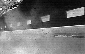
28 Figure A-2. Test Article/Installation before Test A-8
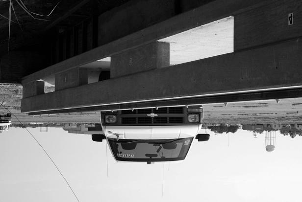
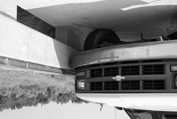
29 CHAPTER 3. CRASH TEST RESULTS TEST NO (NCHRP Report 350 TEST NO. 3-11) Test Vehicle Figures A-3 and A-4 show a 1998 Chevrolet 2500 pickup truck used for the crash test. Test inertia weight of the vehicle was 4498 lb (2042 kg), and its gross static weight was 4498 lb (2042 kg). The height to the lower edge of the vehicle bumper was 17.1 inches (435 mm), and it was 25.8 inches (655 mm) to the upper edge of the bumper. Figure A-5 shows additional dimensions and information on the vehicle. The vehicle was directed into the installation using the cable reverse tow and guidance system, and was released to be free-wheeling and unrestrained just prior to impact. Weather Conditions The test was performed on the morning of March 12, Weather conditions at the time of testing were as follows: Wind speed: 5 mi/h (8 km/h); Wind direction: 0 degrees with respect to the vehicle (vehicle was traveling in a northeasterly direction); Temperature: 52 F (11 C); Relative humidity: 70 percent. Test Description The 4498-lb (2042 kg) pickup truck traveling at 62.8 mi/h (101.0 km/h) impacted the TxDOT T202 (MOD) bridge rail with GFRP 63.0 inches (1600 mm) upstream of leading edge of post 3 at an impact angle of 26.1 degrees. At approximately s after impact, the driver s side door (impact side) opened slightly, and at s the vehicle began to redirect. The right front tire lost contact with the ground at s, followed by the right rear tire at s, and the left front tire at s. At s the vehicle became parallel with the bridge rail and was traveling at a speed of 44.5 mi/h (71.7 km/h). The vehicle lost contact with the bridge rail at s while traveling at a speed of 42.5 mi/h (68.4 km/h) and an exit angle of 18.9 degrees. As the vehicle exited the rail, it came down on the left front quarter panel and rolled onto its left side. The vehicle subsequently came to rest on the left side, ft (52.6 m) downstream of impact and 31.2 ft (9.5 m) forward of the traffic face of the rail. Figures A-6 and A-7 show sequential photographs of the test period. A-9
30 Figure A-3. Vehicle/Installation Geometrics for Test A-10


31 Figure A-4. Vehicle before Test A-11
32 Figure A-5. Vehicle Properties for Test A-12


33 0.000 s s s s s s s s Figure A-6. Sequential Photographs for Test (Frontal View). A-13


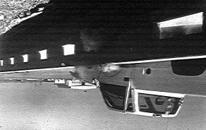
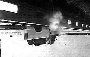
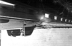
34 0.000 s s s s s s s s Figure A-7. Sequential Photographs for Test (Rear View). A-14
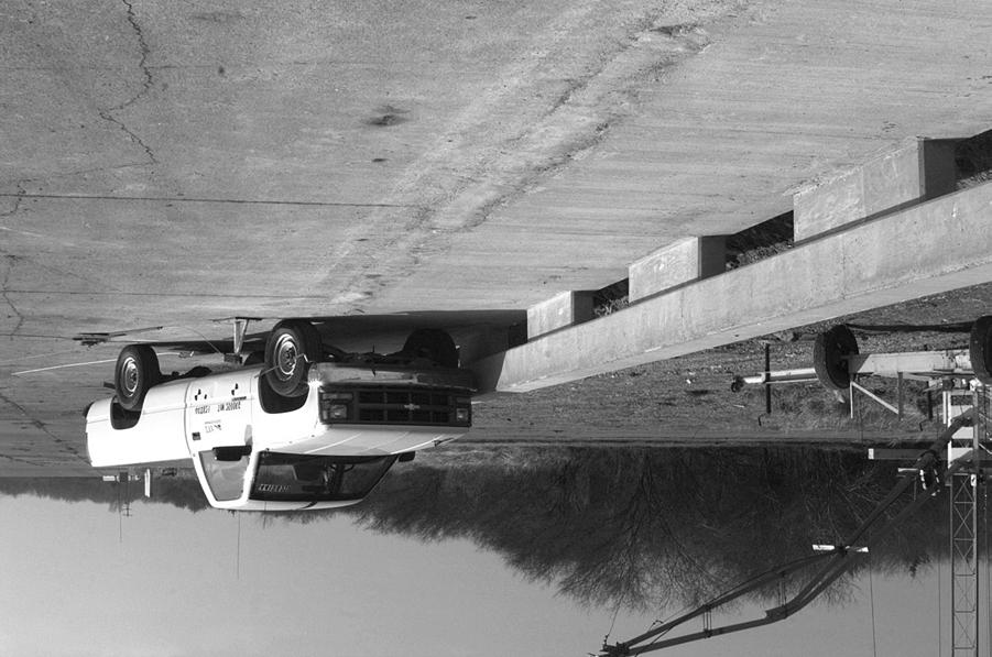
35 Damage to Test Installation Pieces of concrete were chipped out of the lower edge of the beam rail where the vehicle s tire/wheel contacted it. Hairline cracks in the deck radiated from both sides of post 3. The vehicle was in contact with the bridge rail for a distance of ft (4.22 m). Figures A-8 and A-9 show photographs of the damage to the bridge rail. There was no indication of significant structural damage to the rail or the deck. There was no indication that the GFRP exhibited any undesirable traits. Vehicle Damage Figure A-10 shows damage to the vehicle. Structural damage was imparted to the stabilizer bar, left upper and lower A-arms, left rod ends, left front frame member, firewall, and floor pan. Also damaged were the front bumper, hood, radiator, fan, left front tire and wheel rim, left front quarter panel, left door and window glass, and left rear exterior bed. The windshield broke during vehicle rollover. Maximum exterior crush to the exterior of the vehicle was 22.8 inches (580 mm) in the front plane at the left front corner near bumper height. Maximum occupant compartment deformation was 5.0 inches (128 mm) in the floor pan to instrument panel on the left side near the driver s feet. Figure A-11 shows photographs of the interior of the vehicle. Tables A-1 and A-2 show exterior vehicle crush and occupant compartment measurements. Occupant Risk Factors Data from the triaxial accelerometer, located at the vehicle center of gravity, were digitized to compute occupant impact velocity and ridedown accelerations. Only the longitudinal occupant impact velocity and ridedown accelerations are required for evaluation of criterion L of NCHRP Report 350. In the longitudinal direction, occupant impact velocity was 20.3 ft/s (6.2 m/s) at s, maximum s ridedown acceleration was 5.3 g s from to s, and the maximum s average was 10.3 g s between and s. Figure A-12 presents data and other information pertinent to the test. Figures A-13 through A-19 show vehicle angular displacements and accelerations versus time traces. A-15

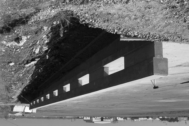
36 Figure A-8. After Impact Trajectory for Test A-16


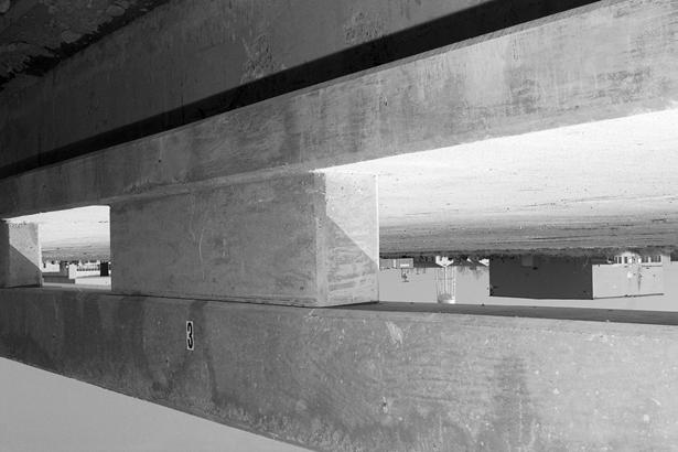
37 Figure A-9. Installation after Test A-17


38 Figure A-10. Vehicle after Test A-18


39 Before Test After Test Figure A-11. Interior of Vehicle for Test A-19
40 Table A-1. Exterior Crush Measurements for Test VEHICLE CRUSH MEASUREMENT SHEET 1 Complete When Applicable End Damage Side Damage Undeformed end width Bowing: B1 X1 Corner shift: A1 B2 X2 End shift at frame (CDC) (check one) A2 < 4 inches > 4 inches Bowing constant X1 + X2 2 = Note: Measure C 1 to C 6 from Driver to Passenger Side in Front or Rear Impacts Rear to Front in Side Impacts. Specific Impact Number Plane* of C-Measurements Direct Damage Width** (CDC) Max*** Crush Field L** C 1 C 2 C 3 C 4 C 5 C 6 ±D 1 Front bumper mm above ground Wheel Well Table taken from National Accident Sampling System (NASS). *Identify the plane at which the C-measurements are taken (e.g., at bumper, above bumper, at sill, above sill, at beltline, etc.) or label adjustments (e.g., free space). Free space value is defined as the distance between the baseline and the original body contour taken at the individual C locations. This may include the following: bumper lead, bumper taper, side protrusion, side taper, etc. Record the value for each C-measurement and maximum crush. **Measure and document on the vehicle diagram the beginning or end of the direct damage width and field L (e.g., side damage with respect to undamaged axle). ***Measure and document on the vehicle diagram the location of the maximum crush. Note: Use as many lines/columns as necessary to describe each damage profile. A-20
41 Table A-2. Occupant Compartment Measurements for Test Truck Occupant Compartment Deformation BEFORE AFTER (mm) (mm) A A A B B B C C C D D D E E F G H I J* *J = measurement laterally across occupant compartment from kickpanel to kickpanel. A-21
 Curb... Test Inertial... Dummy... Gross Static.")
 T202 (MOD) Concrete Bridge Rail With GFRP Reinforcement Concrete Footing Production 2000P 1998 Chevrolet 2500 Pickup 4697 (2133 kg) 4498 (2042 kg) N/A 4498 (2042 kg) Impact Conditions Speed")
... ASI... Max. 0.050-s Average (g's) x-direction... y-direction... z-direction... 62.8 (101 km/h) 26.1 42.5 (68.4 km/h) 18.9 20.3 (6.2 m/s) 23.0 (7.0 m/s) 20.7 (33.")
42 0.000 s s s s A-22 General Information Test Agency... Test No.... Date... Test Article Type... Name... Installation Length (ft)... Material or Key Elements... Soil Type and Condition... Test Vehicle Type... Designation... Model... Mass (lbs) Curb... Test Inertial... Dummy... Gross Static... Texas Transportation Institute /12/02 Bridge Rail T202 (MOD) Bridge Rail With GFRP 95 (28.96 m) T202 (MOD) Concrete Bridge Rail With GFRP Reinforcement Concrete Footing Production 2000P 1998 Chevrolet 2500 Pickup 4697 (2133 kg) 4498 (2042 kg) N/A 4498 (2042 kg) Impact Conditions Speed (mi/h)... Angle (deg)... Exit Conditions Speed (mi/h)... Angle (deg)... Occupant Risk Values Impact Velocity (ft/s) x-direction... y-direction... THIV (mi/h)... Ridedown Accelerations (g's) x-direction... y-direction... PHD (g=s)... ASI... Max s Average (g's) x-direction... y-direction... z-direction (101 km/h) (68.4 km/h) (6.2 m/s) 23.0 (7.0 m/s) 20.7 (33.3 km/h) Test Article Deflections (ft) Dynamic... Permanent... Working Width... Vehicle Damage Exterior VDS... CDC... Maximum Exterior Vehicle Crush (in)... Interior OCDI... Max. Occ. Compart. Deformation (in)... Post-Impact Behavior (during 1.0 s after impact) Max. Yaw Angle (deg)... Max. Pitch Angle (deg)... Max. Roll Angle (deg)... None None 1.72 (0.52 m) 11FL3 11FFAO (580 mm) LF (128 mm) Figure A-12. Summary of Results for Test , NCHRP Report 350 Test 3-11.
43 100 Roll, Pitch and Yaw Angles 50 A-23 Angles (degrees) 0 Test Number: Test Article: T202(MOD) w/gfrp Test Vehicle: 1998 Chevrolet 2500 Pickup Inertial Mass: 2042 kg Gross Mass: 2042 kg Impact Speed: 101 km/h Impact Angle: 26.1 degrees Time (sec) Roll Pitch Yaw Axes are vehicle-fixed. Sequence for determining orientation: 1. Yaw. 2. Pitch. 3. Roll. Figure A-13. Vehicular Angular Displacements for Test
44 20 X Acceleration at CG A-24 Longitudinal Acceleration (g's) Time (sec) Test Number: Test Article: T202(MOD) w/gfrp Reinforcement Test Vehicle: 1998 Chevrolet 2500 Pickup Inertial Mass: 2042 kg Gross Mass: 2042 kg Impact Speed: 101 km/h Impact Angle: 26.1 degrees SAE Class 60 Filter Figure A-14. Vehicle Longitudinal Accelerometer Trace for Test (Accelerometer Located at Center of Gravity).
45 Y Acceleration at CG 50 A-25 Lateral Acceleration (g's) Test Number: Test Article: T202(MOD) w/gfrp Reinforcement Test Vehicle: 1998 Chevrolet 2500 Pickup Inertial Mass: 2042 kg Gross Mass: 2042 kg Impact Speed: 101 km/h Impact Angle: 26.1 degrees Time (sec) SAE Class 60 Filter Figure A-15. Vehicle Lateral Accelerometer Trace for Test (Accelerometer Located at Center of Gravity).
46 20 Z Acceleration at CG A-26 Vertical Acceleration (g's) Test Number: Test Article: T202(MOD) w/gfrp Reinforcement Test Vehicle: 1998 Chevrolet 2500 Pickup -20 Inertial Mass: 2042 kg Gross Mass: 2042 kg Impact Speed: 101 km/h Impact Angle: 26.1 degrees Time (sec) SAE Class 60 Filter Figure A-16. Vehicle Vertical Accelerometer Trace for Test (Accelerometer Located at Center of Gravity).
47 10 X Acceleration Over Rear Axle A-27 Longitudinal Acceleration (g's) Time (sec) Test Number: Test Article: T202(MOD) w/gfrp Reinforcement Test Vehicle: 1998 Chevrolet 2500 Pickup Inertial Mass: 2042 kg Gross Mass: 2042 kg Impact Speed: 101 km/h Impact Angle: 26.1 degrees SAE Class 60 Filter Figure A-17. Vehicle Longitudinal Accelerometer Trace for Test (Accelerometer Located over Rear Axle).
48 Y Acceleration Over Rear Axle 20 A-28 Lateral Acceleration (g's) Test Number: Test Article: T202(MOD) w/gfrp Reinforcement Test Vehicle: 1998 Chevrolet 2500 Pickup Inertial Mass: 2042 kg Gross Mass: 2042 kg Impact Speed: 101 km/h Impact Angle: 26.1 degrees Time (sec) SAE Class 60 Filter Figure A-18. Vehicle Lateral Accelerometer Trace for Test (Accelerometer Located over Rear Axle).
49 10 Z Acceleration Over Rear Axle A-29 Vertical Acceleration (g's) Test Number: Test Article: T202(MOD) w/gfrp Reinforcement Test Vehicle: 1998 Chevrolet 2500 Pickup -10 Inertial Mass: 2042 kg Gross Mass: 2042 kg Impact Speed: 101 km/h Impact Angle: 26.1 degrees Time (sec) SAE Class 60 Filter Figure A-19. Vehicle Vertical Accelerometer Trace for Test (Accelerometer Located over Rear axle).
50
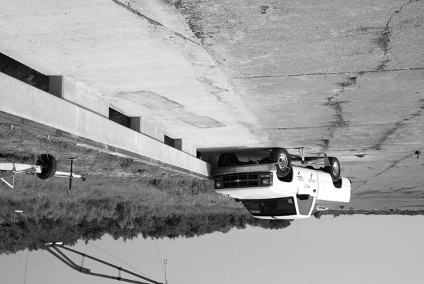
51 CHAPTER 4. SUMMARY AND CONCLUSIONS ASSESSMENT OF TEST RESULTS An assessment of the test based on the applicable NCHRP Report 350 safety evaluation criteria is provided below (4). Structural Adequacy A. Test article should contain and redirect the vehicle; the vehicle should not penetrate, underride, or override the installation although controlled lateral deflection of the test article is acceptable. Results: The TxDOT T202 (MOD) with GFRP reinforcement contained and redirected the 4498-lb (2042 kg) pickup truck. The vehicle did not penetrate, underride, or override the bridge rail. No measurable deflection was noted. Occupant Risk D. Detached elements, fragments, or other debris from the test article should not penetrate or show potential for penetrating the occupant compartment, or present an undue hazard to other traffic, pedestrians, or personnel in a work zone. Deformation of, or intrusions into, the occupant compartment that could cause serious injuries should not be permitted. Results: No detached elements, fragments, or other debris were present to penetrate or to show potential for penetrating the occupant compartment, or to present undue hazard to others in the area. Maximum occupant compartment deformation was 5.0 inches (128 mm) in the floor pan to instrument panel on the left side near the driver s feet. F. The vehicle should remain upright during and after collision although moderate roll, pitching, and yawing are acceptable. Results: The 4498-lb (2042 kg) pickup truck rolled onto its left side after exiting the installation. Vehicle Trajectory K. After collision, it is preferable that the vehicle s trajectory not intrude into adjacent traffic lanes. Results: The vehicle subsequently came to rest on the left side, ft (52.6 m) downstream of impact and 31.2 ft (9.5 m) forward of the traffic face of the rail. A-31
52 L. The occupant impact velocity in the longitudinal direction should not exceed 12 m/s, and the occupant ridedown acceleration in the longitudinal direction should not exceed 20 g s. Results: Longitudinal occupant impact velocity was 20.3 ft/s (6.2 m/s), and longitudinal occupant ridedown acceleration was 5.3 g s. M. The exit angle from the test article preferably should be less than 60 percent of the test impact angle, measured at time of vehicle loss of contact with the test device. Results: Exit angle at loss of contact was 18.9 degrees, which was 72 percent of the impact angle. The following supplemental evaluation factors and terminology, as presented in the FHWA memo entitled Action: Identifying Acceptable Highway Safety Features, were used for visual assessment of test results (20): Passenger Compartment Intrusion 1. Windshield Intrusion a. No windshield contact (broke on roll) e. Complete intrusion into b. Windshield contact, no damage passenger compartment c. Windshield contact, no intrusion f. Partial intrusion into d. Device embedded in windshield, no passenger compartment significant intrusion 2. Body Panel Intrusion yes or no Loss of Vehicle Control 1. Physical loss of control 3. Perceived threat to other vehicles 2. Loss of windshield visibility 4. Debris on pavement Physical Threat to Workers or Other Vehicles 1. Harmful debris that could injure workers or others in the area 2. Harmful debris that could injure occupants in other vehicles No debris was present Vehicle and Device Condition 1. Vehicle Damage a. None d. Major dents to grill and body panels b. Minor scrapes, scratches, or dents e. Major structural damage c. Significant cosmetic dents A-32
53 2. Windshield Damage a. None e. Shattered, remained intact but b. Minor chip or crack partially dislodged c. Broken, no interference with visibility f. Large portion removed d. Broken or shattered, visibility g. Completely removed restricted but remained intact 3. Device Damage a. None d. Substantial, replacement parts b. Superficial needed for repair c. Substantial, but can be straightened e. Cannot be repaired CONCLUSIONS The TxDOT T202 (MOD) bridge rail with GFRP reinforcement contained and redirected the 4498-lb (2042 kg) pickup truck. The vehicle did not penetrate, underride, or override the bridge rail. No measurable deflection was noted. No detached elements, fragments, or other debris were present to penetrate or to show potential for penetrating the occupant compartment, or to present undue hazard to others in the area. Maximum occupant compartment deformation was 5.0 inches (128 mm) in the floor pan to instrument panel on the left side near the driver s feet. The 4498-lb (2042 kg) pickup truck rolled onto its left side after exiting the installation. The vehicle subsequently came to rest on the left side, ft (52.6 m) downstream of impact and 31.2 ft (9.5 m) forward of the traffic face of the rail. Longitudinal occupant impact velocity was 20.3 ft/s (6.2 m/s) and longitudinal occupant ridedown acceleration was 5.3 g s. Exit angle at loss of contact was 18.9 degrees, which was 72 percent of the impact angle. As seen in Table A-3, the TxDOT T202 (MOD) bridge rail with GFRP reinforcement did not pass the required specifications for occupant risk during NCHRP Report 350 Test 3-11 due to rollover. No significant structural damage occurred to the rail or the deck. There was no indication that the GFRP exhibited any undesirable traits. IMPLEMENTATION STATEMENT No implementation is indicated at this time. A-33
54 Table A-3. Performance Evaluation Summary for Test , NCHRP Report 350 Test A-34 Test Agency: Texas Transportation Institute Test No.: Test Date: 03/12/2002 NCHRP Report 350 Test 3-11 Evaluation Criteria Test Results Assessment Structural Adequacy A. Test article should contain and redirect the vehicle; the vehicle should not penetrate, underride, or override the installation although controlled lateral deflection of the test article is acceptable. Occupant Risk D. Detached elements, fragments, or other debris from the test article should not penetrate or show potential for penetrating the occupant compartment, or present an undue hazard to other traffic, pedestrians, or personnel in a work zone. Deformations of, or intrusions into, the occupant compartment that could cause serious injuries should not be permitted. F. The vehicle should remain upright during and after collision although moderate roll, pitching, and yawing are acceptable. Vehicle Trajectory K. After collision it is preferable that the vehicle s trajectory not intrude into adjacent traffic lanes. L. The occupant impact velocity in the longitudinal direction should not exceed 12 m/s, and the occupant ridedown acceleration in the longitudinal direction should not exceed 20 g s. M. The exit angle from the test article preferably should be less than 60 percent of test impact angle, measured at time of vehicle loss of contact with test device. *Criteria K and M are preferable, not required. The TxDOT T202 (MOD) with GFRP reinforcement contained and redirected the 4498-lb (2042 kg) pickup truck. The vehicle did not penetrate, underride, or override the bridge rail. No measurable deflection was noted. No detached elements, fragments, or other debris were present to penetrate or to show potential for penetrating the occupant compartment, or to present undue hazard to others in the area. Maximum occupant compartment deformation was 5.0 inches (128 mm) in the floor pan to instrument panel on the left side near the driver s feet. The 4498-lb (2042 kg) pickup truck rolled onto its left side after exiting the installation. The vehicle subsequently came to rest on the left side, 52.6 m downstream of impact and 9.5 m forward of the traffic face of the rail. Longitudinal occupant impact velocity was 20.3 ft/s (6.2 m/s), and longitudinal occupant ridedown acceleration was 5.3 g s. Exit angle at loss of contact was 18.9 degrees, which was 72 percent of the impact angle. Pass Pass Fail Fail* Pass Fail*
55 APPENDIX B: NCHRP REPORT 350 TEST 3-11 OF THE TXDOT T202 (MOD) BRIDGE RAIL WITH GFRP REINFORCEMENT AND METAL RAIL CHAPTER 1. INTRODUCTION PROBLEM In some areas of the state, corrosion of reinforcing steel in concrete bridge structures, especially in deck slabs, continues to be a serious problem for the Texas Department of Transportation (TxDOT). One remedial measure for this problem might be the use of glass fiber reinforced polymer (GFRP) reinforcing bars. Physical properties of these reinforcing bars differ significantly from those of conventional reinforcing steel, and the behavior of concrete reinforced with GFRP is not completely defined and understood. GFRP reinforcement is typically much more brittle than conventional reinforcing steel, and its behavior under dynamic load from a vehicle collision is not known. This project addresses the behavior of a bridge slab/rail structure reinforced with glass fiber reinforced polymer when subjected to full-scale vehicle crash tests. BACKGROUND Use of GFRP reinforcement in decks, rails, and perhaps other elements of bridge structures has high potential for reducing the problem of deterioration of bridge structures as a result of corrosion of reinforcement. Glass fiber reinforced polymer reinforcement cannot be used as a direct replacement for steel because GFRP has significantly different mechanical properties. One major fundamental difference is that GFRP is a relatively brittle material while steel is ductile. Ductility of steel is the fundamental property that allows one to design reinforced concrete structures that behave in a ductile manner, although the (plain) concrete is brittle. This ductility is accomplished by providing ratios of steel reinforcement that cause the steel to yield before the concrete ruptures in a brittle manner. With the use of GFRP, the greatest amount of structural ductility is achieved by proportioning the materials such that the concrete ruptures first because it is the more ductile of the two materials. This is expected to result in a bridge structure that is somewhat more brittle than a structure with conventional steel reinforcement and, therefore, its behavior under dynamic loads needs to be evaluated. Sufficient ductility and/or reserve strength for adequate performance in service must exist. OBJECTIVES/SCOPE OF RESEARCH TxDOT Project , FRP Reinforcing Bars in Bridge Decks was initiated in August This was a joint project involving the Texas Transportation Institute, the University of Texas at Arlington, and Texas Tech University. In that project, GFRP reinforcement was used on a trial basis in the top of a bridge deck in selected spans in a structure in Potter County. Behavior of the GFRP was monitored during construction, and monitoring will continue while B-1
56 the bridge is in service. Also, extensive laboratory studies of the fundamental properties and behavior of concrete reinforced with GFRP were undertaken. TTI researchers have performed full-scale vehicle crash tests on concrete bridge rails with conventional steel reinforcement that are now TxDOT standard bridge rails (3, 6-19). In some instances, TTI researchers worked cooperatively with TxDOT engineers to develop the design details of the bridge rail. These bridge rails are now being used throughout the state with some of them being more popular in some areas. Several rail designs that are used more in the areas of the state where corrosion continues to be a major problem were considered for inclusion in this project. Should the project demonstrate that partial or full replacement of steel reinforcement with GFRP reinforcement is acceptable, those rail designs will be available and approved for use in areas of the state that need to address problems with corrosion. TxDOT currently uses several standard concrete bridge rails. They include the T201, T202 (MOD), T4, and the T500 series. The TTI researchers met with TxDOT personnel to review usage of the various designs and selected the T202 (MOD) bridge rail design for testing and evaluation. Design details, including replacement of reinforcing steel with GFRP, were established in concert with TxDOT engineers. TTI researchers performed calculations to determine the strength of the T202 (MOD) rail and posts using conventional steel reinforcement and details as shown on a TxDOT drawing entitled Type T202 (MOD) and dated September Using these calculated strengths, TTI researchers then performed calculations to determine the required GFRP reinforcement needed in the rail and posts using the American Concrete Institute (ACI) 440.1R-01 Guide for the Design and Construction of Concrete Reinforced with FRP Bars (1). GFRP reinforcement loses some strength with age. The guide accounts for the loss in strength by using an environmental reduction factor, C E, for various fiber type and exposure conditions in design calculations. Two designs were used. The first used a factor of C E = 0.7. This design would have the required strength after long-term exposure to the environment. The second design used a factor of C E = 1.0. This design resulted in a reduced amount of reinforcement that would, at the time of testing, represent the strength that would exist after aging. A full-scale test installation was then constructed using the required GFRP reinforcement for both designs. One-half of the rail was reinforced with the amount of reinforcement required by the guide and the remaining one-half was reinforced with a reduced amount of reinforcement that would represent loss of strength with age. Researchers performed a full-scale vehicle crash test on the maximum strength design case (C E = 0.7). In that test, the vehicle rolled onto its side and thus failed the safety requirements of National Cooperative Highway Research Program (NCHRP) Report 350 (4). However, structural behavior of the bridge rail (with GFRP reinforcement) was entirely acceptable. An earlier report presented the results of that test (21). This outcome presented a dilemma because the Type T202 (MOD) bridge rail had acceptable safety performance in two previous tests (test 3-11 of NCHRP Report 350) (2,3). There was some indication that the 27-inches (686 mm) height of the rail was marginal and was the cause of the rollover. B-2
57 After deliberations, it was decided that the need to test the railing with reduced amount of reinforcement (C E = 1.0) was still valid. Height of the rail was increased 3 inches (76 mm) by adding a TS6 3 1/4 inch (TS ) member on top of the existing test article. This test article was then subjected to NCHRP Report 350 test designation Test 3-11 is a strength test for Test Level 3 (TL-3) of NCHRP Report 350 and involves a 4405-lb (2000 kg) pickup truck traveling at 62.1 mi/h (100 km/h) and impacting the railing at an approach angle of 25 degrees. Researchers used standard evaluation criteria of NCHRP Report 350 for evaluating safety performance of the railing. Next they evaluated the structural behavior of the railing and deck overhang in detail to determine behavior of the GFRP reinforcement. B-3
58
59 CHAPTER 2. PROJECT APPROACH TEST FACILITY The test facilities at the Texas Transportation Institute s Proving Ground consist of an 2,000 acre (809-hectare) complex of research and training facilities situated 10 miles (16 km) northwest of the main campus of Texas A&M University. The site, formerly an air force base, has large expanses of concrete runways and parking aprons well suited for experimental research and testing in the areas of vehicle performance and handling, vehicle-roadway interaction, durability and efficacy of highway pavements, and safety evaluation of roadside safety hardware. The site selected for construction of the TxDOT T202 (MOD) bridge rail with GFRP is along a wide out-of-service apron/runway. The apron/runway consists of an unreinforced jointed concrete pavement in 12.5 ft by 15.0 ft (3.8 m by 4.6 m) blocks nominally 8 to 12 inches (203 to 305 mm) deep. The aprons and runways are about 50 years old, and the joints have some displacement, but are otherwise flat and level. TEST ARTICLE The bridge deck cantilever constructed for this project was 2 ft-4 3/8 inches (721 mm) in width and 8 inches (203 mm) thick. The bridge deck was constructed immediately adjacent to an existing concrete runway located at the TTI test facility. The concrete deck was anchored into the existing runway with #5 (#16) steel reinforcement in the bottom layer in the deck overhang. The transverse reinforcement in the top and bottom layers of reinforcing in the deck cantilever consisted of #6 (#19) GFRP bars spaced 5½ inches (140 mm) apart. The longitudinal reinforcement in the top of the deck cantilever consisted of #5 (#16) GFRP bars spaced 9 inches (229 mm) apart. The longitudinal reinforcement in the bottom of the deck consisted of two #5 (#16) bars on the field side of the deck spaced 3 inches (75 mm) apart with the next adjacent #5 (#16) bar spaced 12 inches (305 mm) toward the traffic face. Transit Mix Concrete and Materials, Bryan, Texas, provided the concrete used for this project. TxDOT Class S concrete was used to construct the deck cantilever. The average compressive strength of the Class S concrete exceeded the required strength of 4000 psi (28 MPa) at the time the test was performed. The T202 (MOD) bridge rail consists of a 1 ft-1½ inches 1 ft-2 inches (343 mm 356 mm) concrete bridge rail supported by 7½ inches 5 ft-0 inch (191 mm 1524 mm) concrete posts spaced 5 ft-0 inch (1524 mm) apart. The total height of the T202 (MOD) bridge rail was 2 ft-3 inches (686 mm). Researchers constructed two separate designs within this test installation. The details of the reduced strength design (C E = 1.0) are reported herein. For details of both designs, please refer to the drawings shown as Figure B-1 in this report. For the reduced strength design, vertical reinforcement in each post consisted of 13 #6 (#19) L shaped GFRP bars equally spaced on the front face (traffic side) and nine straight #5 (#16) GFRP bars equally spaced on the back face (field side). Longitudinal reinforcement in each post consisted of a #4 (#13) GFRP bar located on the front and back faces. Reinforcement in the rail consisted of four longitudinal #4 GFRP bars equally spaced on both the front and back faces of the rail B-5
60 B-6 Figure B-1. Details of the TxDOT T202 (MOD) Bridge Rail with GFRP and Metal Rail.
61 B-7 Figure B-1. Details of the TxDOT T202 (MOD) Bridge Rail with GFRP and Metal Rail (Continued).
62 B-8 Figure B-1. Details of the TxDOT T202 (MOD) Bridge Rail with GFRP and Metal Rail (Continued).
63 B-9 Figure B-1. Details of the TxDOT T202 (MOD) Bridge Rail with GFRP and Metal Rail (Continued).
64 (eight total). This longitudinal reinforcement was enclosed by #4 (#13) GFRP stirrups spaced 4½ inches (114 mm) apart. Researchers constructed each stirrup using two U shaped bars that were lapped together on the vertical faces of the rail. Hughes Brothers in Seward, Nebraska, provided all the GFRP reinforcement used for this project. TxDOT Class C concrete was used to construct the bridge rail. The average compressive strength of the Class C concrete exceeded the required strength of 3600 psi (25 MPa) at the time the test was performed. In an effort to enhance vehicle performance, the height of the rail was increased to 30 inches (762 mm). This modification was achieved by attaching a TS6 3 ¼ (TS 152 mm 76 mm 6 mm) steel tube to the top of the concrete rail and flush with the traffic face of the rail. The steel tube was anchored to the top of the concrete rail using ¾-inch (19 mm) diameter Hilti Kwik Bolt II anchor bolts spaced 2 ft-6 inches (0.76 m) apart. Please refer to Figure B-1 for additional details. Figure B-2 shows photographs of the completed installation. CRASH TEST CONDITIONS NCHRP Report 350 recommends two tests for Test Level 3 evaluation of longitudinal barriers, such as the T202 (MOD) with GFRP reinforcement: NCHRP Report 350 test designation 3-10: This test involves an 1806-lb (820 kg) passenger car impacting the critical impact point (CIP) in the length of need (LON) of the longitudinal barrier at a nominal speed and angle of 62 mi/h (100 km/h) and 20 degrees. The purpose of this test is to evaluate the overall performance of the LON section in general and occupant risks in particular. NCHRP Report 350 test designation 3-11: This test involves a 4405-lb (2000 kg) pickup truck impacting the CIP in the LON of the longitudinal barrier at a nominal speed and angle of 62 mi/h (100 km/h) and 25 degrees. The test is intended to evaluate the strength of the section for containing and redirecting the pickup truck. This report documents the results of test , which corresponds to NCHRP Report 350 test designation The crash test and data analysis procedures were in accordance with guidelines presented in NCHRP Report 350. Appendix C presents brief descriptions of these procedures. EVALUATION CRITERIA The crash test performed was evaluated in accordance with NCHRP Report 350. As stated in NCHRP Report 350, Safety performance of a highway appurtenance cannot be measured directly but can be judged on the basis of three factors: structural adequacy, occupant risk, and vehicle trajectory after collision. Accordingly, researchers used the safety evaluation criteria from Table 5.1 of NCHRP Report 350 to evaluate the crash test reported herein. B-10


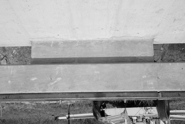
65 Figure B-2. Test Article/Installation before Test B-11
66
67 CHAPTER 3. CRASH TEST RESULTS TEST NO (NCHRP Report 350 TEST NO. 3-11) Test Vehicle Figures B-3 and B-4 show the 1997 Chevrolet 2500 pickup truck used for the crash test. Test inertia mass of the vehicle was 4502 lb (2044 kg), and its gross static mass was 4502 lb (2044 kg). The height to the lower edge of the vehicle bumper was 17.3 inches (440 mm), and it was 25.9 inches (660 mm) to the upper edge of the bumper. Figure B-5 shows additional dimensions and information on the vehicle. The vehicle was directed into the installation using the cable reverse tow and guidance system, and was released to be free-wheeling and unrestrained just prior to impact. Weather Conditions Researchers performed the test on the morning of June 14, Weather conditions at the time of testing were as follows: Wind speed: 10 mi/h (16 km/h); Wind direction: 180 degrees with respect to the vehicle (vehicle was traveling in a southwesterly direction); Temperature: 84 F (29 C); Relative humidity: 63 percent. Test Description The 4502-lb (2044 kg) pickup truck traveling at 62.6 mi/h (100.7 km/h) impacted the TxDOT T202 (MOD) bridge rail with GFRP 54.7 inches (1390 mm) upstream of leading edge of post 3 at an impact angle of 25.0 degrees. At approximately s after impact, the passenger s side door (impact side) opened slightly, and at s the vehicle began to redirect. The left front tire lost contact with the ground at s. At s the vehicle became parallel with the bridge rail and was traveling at a speed of 48.3 mi/h (77.7 km/h). The vehicle lost contact with the bridge rail at s while traveling at a speed of 41.6 mi/h (66.9 km/h) and an exit angle of 14.2 degrees. Brakes on the vehicle were applied at 1.8 s after impact. The vehicle subsequently came to rest upright, ft (57.2 m) downstream of impact and 15.7 ft (4.8 m) forward of the traffic face of the rail. Figures B-6 and B-7 show sequential photographs of the test period. B-13
68 Figure B-3. Vehicle/Installation Geometrics for Test B-14


69 Figure B-4. Vehicle before Test B-15
70 Figure B-5. Vehicle Properties for Test B-16


71 0.000 s s s s Figure B-6. Sequential Photographs for Test (Overhead and Frontal Views). B-17


72 0.276 s s s s Figure B-6. Sequential Photographs for Test (Overhead and Frontal Views) (Continued). B-18


73 0.000 s s s s s s s s Figure B-7. Sequential Photographs for Test (Rear View). B-19
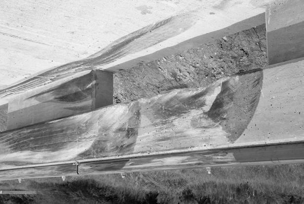
74 Damage to Test Installation Tire marks were located on the face of post 8 and small pieces of concrete were chipped out of the underside of lower edge of the beam rail between posts 8 and 9 where the vehicle s tire/wheel contacted it. The upper beam experienced hairline cracks 14.2 inches (360 mm) and 33.9 inches (860 mm) upstream of post 8. No cracks were evident in the deck. The vehicle was in contact with the bridge rail for a distance of ft (3.97 m). Figures B-8 and B-9 show photographs of the damage to the bridge rail. There was no indication of significant structural damage to the rail or the deck. There was no indication that the GFRP exhibited any undesirable traits. Vehicle Damage Figure B-10 shows damage to the vehicle. Structural damage was imparted to the stabilizer bar, right upper and lower A-arms, right spindle, right rod ends, right front frame member, firewall, and floor pan. Also damaged were the front bumper, hood, radiator, fan, right front tire and wheel rim, right front quarter panel, right door, right rear exterior bed and right rear tire and wheel rim. The windshield sustained stress cracks. Maximum exterior crush to the exterior of the vehicle was 23.6 inches (600 mm) in the front plane at the right front corner near bumper height. Maximum occupant compartment deformation was 5.6 inches (143 mm) in the kick panel area on the passenger s side. Figure B-11 shows photographs of the interior of the vehicle. Tables B-1 and B-2 show exterior vehicle crush and occupant compartment measurements. Occupant Risk Factors Data from the tri-axial accelerometer, located at the vehicle center of gravity, were digitized to compute occupant impact velocity and ridedown accelerations. Only the longitudinal occupant impact velocity and ridedown accelerations are required for evaluation of criterion L of NCHRP Report 350. In the longitudinal direction, occupant impact velocity was 21.3 ft/s (6.5 m/s) at s, maximum s ridedown acceleration was 4.6 g s from to s, and the maximum s average was 10.6 g s between and s. Figure B-12 presents data and other information pertinent to the test. Figures B-13 through B-19 show vehicle angular displacements and accelerations versus time traces. B-20

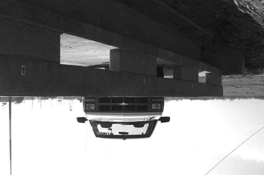
75 Figure B-8. After Impact Trajectory for Test B-21


76 Figure B-9. Installation after Test B-22


77 Figure B-10. Vehicle after Test B-23


78 Before Test After Test Figure B-11. Interior of Vehicle for Test B-24
79 Table B-1. Exterior Crush Measurements For Test VEHICLE CRUSH MEASUREMENT SHEET 1 Complete When Applicable End Damage Side Damage Undeformed end width Bowing: B1 X1 Corner shift: A1 B2 X2 End shift at frame (CDC) (check one) A2 < 4 inches > 4 inches Bowing constant X1 + X2 2 = Note: Measure C 1 to C 6 from Driver to Passenger side in Front or Rear impacts Rear to Front in Side Impacts. Specific Impact Number Plane* of C-Measurements Direct Damage Width** (CDC) Max*** Crush Field L** C 1 C 2 C 3 C 4 C 5 C 6 ±D 1 Front bumper mm above ground Wheel Well Table taken from National Accident Sampling System (NASS). *Identify the plane at which the C-measurements are taken (e.g., at bumper, above bumper, at sill, above sill, at beltline, etc.) or label adjustments (e.g., free space). Free space value is defined as the distance between the baseline and the original body contour taken at the individual C locations. This may include the following: bumper lead, bumper taper, side protrusion, side taper, etc. Record the value for each C-measurement and maximum crush. **Measure and document on the vehicle diagram the beginning or end of the direct damage width and field L (e.g., side damage with respect to undamaged axle). ***Measure and document on the vehicle diagram the location of the maximum crush. Note: Use as many lines/columns as necessary to describe each damage profile. B-25
 AFTER (mm) A1 870 880 A2 930 926 A3 910 895 B1 1075 1065 B2 1030 958 B3 1070 1155 C1 1375 1375 C2 535 510 C3 1368 1315 D1 320 333 D2 161 145 D3 315 412 E1 1582 1587 E2 1592 1635 F 1460")
80 Table B-2. Occupant Compartment Measurements For Test Occupant Compartment Deformation *J = measurement laterally across occupant compartment from kickpanel to kickpanel. BEFORE (mm) AFTER (mm) A A A B B B C C C D D D E E F G H I J* T r u c k B-26
 Curb... Test Inertial... Dummy... Gross Static.")
 T202(MOD) Concrete Bridge Rail With GFRP Reinforcement And Metal Rail Concrete Footing Production 2000P 1997 Chevrolet 2500 Pickup 4761 (2162 kg) 4501 (2044 kg) N/A 4501 (2044 kg) Impact")
 x-direction... y-direction... PHD (g=s)... ASI... Max. 0.050-s Average (g's) x-direction... y-direction... z-direction... 62.6 (100.7 km/h) 25.0 41.6 (66.9 km/h) 14.")
... Interior OCDI... Max. Occ. Compart. Deformation (inch)... Post-Impact Behavior (during 1.0 s after impact) Max. Yaw Angle (deg)... Max. Pitch Angle (deg).")
81 0.000 s s s s B-27 General Information Test Agency... Test No.... Date... Test Article Type... Name... Installation Length (ft)... Material or Key Elements... Soil Type and Condition... Test Vehicle Type... Designation... Model... Mass (lbs) Curb... Test Inertial... Dummy... Gross Static... Texas Transportation Institute /14/02 Bridge Rail T202 (MOD) Bridge Rail With GFRP and Metal Rail 95 (29.0 m) T202(MOD) Concrete Bridge Rail With GFRP Reinforcement And Metal Rail Concrete Footing Production 2000P 1997 Chevrolet 2500 Pickup 4761 (2162 kg) 4501 (2044 kg) N/A 4501 (2044 kg) Impact Conditions Speed (mi/h)... Angle (deg)... Exit Conditions Speed (mi/h)... Angle (deg)... Occupant Risk Values Impact Velocity (ft/s) x-direction... y-direction... THIV (mi/h)... Ridedown Accelerations (g's) x-direction... y-direction... PHD (g=s)... ASI... Max s Average (g's) x-direction... y-direction... z-direction (100.7 km/h) (66.9 km/h) (6.5 m/s) 23.9 (7.3 m/s) 21.5 (34.6 km/h) Test Article Deflections (ft) Dynamic... Permanent... Working Width... Vehicle Damage Exterior VDS... CDC... Maximum Exterior Vehicle Crush (inch)... Interior OCDI... Max. Occ. Compart. Deformation (inch)... Post-Impact Behavior (during 1.0 s after impact) Max. Yaw Angle (deg)... Max. Pitch Angle (deg)... Max. Roll Angle (deg)... None None 1.61 (0.49 m) 01FR3 01FREW3 5.6 (143 mm) RF (600 mm) Figure B-12. Summary of Results for Test , NCHRP Report 350 Test 3-11.
Form DOT F (8-72) Texas Transportation Institute The Texas A&M University System College Station, Texas
 Texas Transportation Institute The Texas A&M University System College Station, Texas") 1. Report No. FHWA/TX-02/4162-1 Technical Report Documentation Page 2. Government Accession No. 3. Recipient's Catalog No. 4. Title and Subtitle EVALUATION OF TEXAS GRID-SLOT PORTABLE CONCRETE BARRIER
1. Report No. FHWA/TX-02/4162-1 Technical Report Documentation Page 2. Government Accession No. 3. Recipient's Catalog No. 4. Title and Subtitle EVALUATION OF TEXAS GRID-SLOT PORTABLE CONCRETE BARRIER
Texas Transportation Institute The Texas A&M University System College Station, Texas
 1. Report No. FHWA/TX-04/9-8132-1 4. Title and Subtitle TESTING AND EVALUATION OF THE FLORIDA JERSEY SAFETY SHAPED BRIDGE RAIL 2. Government Accession No. 3. Recipient's Catalog No. 5. Report Date February
NCHRP Report 350 Crash Testing and Evaluation of the S-Square Mailbox System
 TTI: 0-5210 NCHRP Report 350 Crash Testing and Evaluation of the S-Square Mailbox System ISO 17025 Laboratory Testing Certificate # 2821.01 Crash testing performed at: TTI Proving Ground 3100 SH 47, Building
MASH Test 3-11 on the T131RC Bridge Rail
 TTI: 9-1002-12 MASH Test 3-11 on the T131RC Bridge Rail ISO 17025 Laboratory Testing Certificate # 2821.01 Crash testing performed at: TTI Proving Ground 3100 SH 47, Building 7091 Bryan, TX 77807 Test
Texas Transportation Institute The Texas A&M University System College Station, Texas
 1. Report No. FHWA/TX-05/9-8132-P7 4. Title and Subtitle TL-4 CRASH TESTING OF THE F411 BRIDGE RAIL 2. Government Accession No. 3. Recipient's Catalog No. 5. Report Date October 2004 Technical Report Documentation
A MASH Compliant W-Beam Median Guardrail System
 0 0 0 0 0 A MASH Compliant W-Beam Median Guardrail System By A. Y. Abu-Odeh, R. P. Bligh, W. Odell, A. Meza, and W. L. Menges Submitted: July 0, 0 Word Count:, + ( figures + tables=,000) =, words Authors:
MASH TEST 3-11 OF THE TxDOT T222 BRIDGE RAIL
 TTI: 9-1002-12 MASH TEST 3-11 OF THE TxDOT T222 BRIDGE RAIL ISO 17025 Laboratory Testing Certificate # 2821.01 Crash testing performed at: TTI Proving Ground 3100 SH 47, Building 7091 Bryan, TX 77807 Test
GUARDRAIL TESTING MODIFIED ECCENTRIC LOADER TERMINAL (MELT) AT NCHRP 350 TL-2. Dean C. Alberson, Wanda L. Menges, and Rebecca R.
 AT NCHRP 350 TL-2. Dean C. Alberson, Wanda L. Menges, and Rebecca R.") GUARDRAIL TESTING MODIFIED ECCENTRIC LOADER TERMINAL (MELT) AT NCHRP 350 TL-2 Dean C. Alberson, Wanda L. Menges, and Rebecca R. Haug Prepared for The New England Transportation Consortium July 2002 NETCR
GUARDRAIL TESTING MODIFIED ECCENTRIC LOADER TERMINAL (MELT) AT NCHRP 350 TL-2 Dean C. Alberson, Wanda L. Menges, and Rebecca R. Haug Prepared for The New England Transportation Consortium July 2002 NETCR
CRASH TEST AND EVALUATION OF 3-FT MOUNTING HEIGHT SIGN SUPPORT SYSTEM
 TTI: 9-1002-15 CRASH TEST AND EVALUATION OF 3-FT MOUNTING HEIGHT SIGN SUPPORT SYSTEM ISO 17025 Laboratory Testing Certificate # 2821.01 Crash testing performed at: TTI Proving Ground 3100 SH 47, Building
Texas Transportation Institute The Texas A&M University System College Station, Texas
 1. Report No. FHWA/TX-07/0-5527-1 4. Title and Subtitle DEVELOPMENT OF A LOW-PROFILE TO F-SHAPE TRANSITION BARRIER SEGMENT 2. Government Accession No. 3. Recipient's Catalog No. Technical Report Documentation
MASH TEST 3-11 OF THE TxDOT SINGLE SLOPE BRIDGE RAIL (TYPE SSTR) ON PAN-FORMED BRIDGE DECK
 ON PAN-FORMED BRIDGE DECK") TTI: 9-1002 MASH TEST 3-11 OF THE TxDOT SINGLE SLOPE BRIDGE RAIL (TYPE SSTR) ON PAN-FORMED BRIDGE DECK ISO 17025 Laboratory Testing Certificate # 2821.01 Crash testing performed at: TTI Proving Ground
TTI: 9-1002 MASH TEST 3-11 OF THE TxDOT SINGLE SLOPE BRIDGE RAIL (TYPE SSTR) ON PAN-FORMED BRIDGE DECK ISO 17025 Laboratory Testing Certificate # 2821.01 Crash testing performed at: TTI Proving Ground
NCHRP Report 350 Test 4-12 of the Modified Thrie Beam Guardrail
 NCHRP Report 350 Test 4-12 of the Modified Thrie Beam Guardrail PUBLICATION NO. FHWA-RD-99-065 DECEMBER 1999 Research, Development, and Technology Turner-Fairbank Highway Research Center 6300 Georgetown
Technical Report Documentation Page Form DOT F (8-72) Reproduction of completed page authorized
 Reproduction of completed page authorized") 1. Report No. FHWA/TX-05/0-4162-3 4. Title and Subtitle 2. Government Accession No. 3. Recipient's Catalog No. DEVELOPMENT OF LOW-DEFLECTION PRECAST CONCRETE ARRIER 5. Report Date January 2005 Technical
1. Report No. FHWA/TX-05/0-4162-3 4. Title and Subtitle 2. Government Accession No. 3. Recipient's Catalog No. DEVELOPMENT OF LOW-DEFLECTION PRECAST CONCRETE ARRIER 5. Report Date January 2005 Technical
MASH08 TEST 3-11 OF THE ROCKINGHAM PRECAST CONCRETE BARRIER
 Proving Ground Report No. 400001-RPC4 Report Date: July 2009 MASH08 TEST 3-11 OF THE ROCKINGHAM PRECAST CONCRETE BARRIER by C. Eugene Buth, P.E. Research Engineer William F. Williams, P.E. Assistant Research
MASH TEST 3-37 OF THE TxDOT 31-INCH W-BEAM DOWNSTREAM ANCHOR TERMINAL
 TTI: 9-1002 MASH TEST 3-37 OF THE TxDOT 31-INCH W-BEAM DOWNSTREAM ANCHOR TERMINAL ISO 17025 Laboratory Testing Certificate # 2821.01 Crash testing performed at: TTI Proving Ground 3100 SH 47, Building
TEXAS TRANSPORTATION INSTITUTE THE TEXAS A & M UNIVERSITY SYSTEM COLLEGE STATION, TEXAS 77843
 NCHRP REPORT 350 ASSESSMENT OF EXISTING ROADSIDE SAFETY HARDWARE by C. Eugene Buth, P.E. Senior Research Engineer Wanda L. Menges Associate Research Specialist and Sandra K. Schoeneman Research Associate
TEXAS TRANSPORTATION INSTITUTE THE TEXAS A & M UNIVERSITY SYSTEM COLLEGE STATION, TEXAS 77843
 NCHRP REPORT 350 TEST 3-11 OF THE NEW YORK DOT PORTABLE CONCRETE BARRIER WITH I-BEAM CONNECTION (RETEST) by Roger P. Bligh, P.E. Assistant Research Engineer Wanda L. Menges Associate Research Specialist
February 8, In Reply Refer To: HSSD/CC-104
 February 8, 2008 200 New Jersey Avenue, SE. Washington, DC 20590 In Reply Refer To: HSSD/CC-04 Barry D. Stephens, P.E. Sr. Vice President Engineering Energy Absorption Systems, Inc. 367 Cincinnati Avenue
July 10, Refer to: HSA-10/CC-78A
 July 10, 2003 Refer to: HSA-10/CC-78A Barry D. Stephens, P.E. Senior Vice President of Engineering ENERGY ABSORPTION Systems, Inc. 3617 Cincinnati Avenue Rocklin, California 95765 Dear Mr. Stephens: Your
Manual for Assessing Safety Hardware
 American Association of State Highway and Transportation Officials Manual for Assessing Safety Hardware 2009 vii PREFACE Effective traffic barrier systems, end treatments, crash cushions, breakaway devices,
TEXAS TRANSPORTATION INSTITUTE THE TEXAS A & M UNIVERSITY SYSTEM COLLEGE STATION, TEXAS 77843
 NCHRP REPORT 350 TEST 3-11 OF THE STEEL-BACKED TIMBER GUARDRAIL by D. Lance Bullard, Jr., P.E. Associate Research Engineer Wanda L. Menges Associate Research Specialist and Sandra K. Schoeneman Research
STI Project: Barrier Systems, Inc. RTS-QMB Longitudinal Barrier. Page 38 of 40 QBOR1. Appendix F (Continued) Figure F-3
 Figure F-3") Barrier Systems, Inc. RTS-QMB Longitudinal Barrier STI Project: QBOR1 Page 38 of 40 Appendix F (Continued) Figure F-3 t=.500sec 115 meters overall 37.1 Impact Severity (kj).. 141.6 Angle (deg).. 25 Speed
Barrier Systems, Inc. RTS-QMB Longitudinal Barrier STI Project: QBOR1 Page 38 of 40 Appendix F (Continued) Figure F-3 t=.500sec 115 meters overall 37.1 Impact Severity (kj).. 141.6 Angle (deg).. 25 Speed
Evaluation of Barriers for Very High Speed Roadways
 TTI: 0-6071 Evaluation of Barriers for Very High Speed Roadways ISO 17025 Laboratory Testing Certificate # 2821.01 Crash testing performed at: TTI Proving Ground 3100 SH 47, Building 7091 Bryan, TX 77807
TEXAS TRANSPORTATION INSTITUTE THE TEXAS A & M UNIVERSITY SYSTEM COLLEGE STATION, TEXAS
 NCHRP REPORT 350 TEST 4-21 OF THE ALASKA MULTI-STATE BRIDGE RAIL THRIE-BEAM TRANSITION by C. Eugene Buth Senior Research Engineer William F. Williams Assistant Research Engineer Wanda L. Menges Associate
CRASH TEST AND EVALUATION OF TEMPORARY WOOD SIGN SUPPORT SYSTEM FOR LARGE GUIDE SIGNS
 TTI: 9-1002-15 CRASH TEST AND EVALUATION OF TEMPORARY WOOD SIGN SUPPORT SYSTEM FOR LARGE GUIDE SIGNS ISO 17025 Laboratory Testing Certificate # 2821.01 Crash testing performed at: TTI Proving Ground 3100
Advances in Simulating Corrugated Beam Barriers under Vehicular Impact
 13 th International LS-DYNA Users Conference Session: Automotive Advances in Simulating Corrugated Beam Barriers under Vehicular Impact Akram Abu-Odeh Texas A&M Transportation Institute Abstract W-beam
MASH TEST 3-21 ON TL-3 THRIE BEAM TRANSITION WITHOUT CURB
 TTI: 9-1002-12 MASH TEST 3-21 ON TL-3 THRIE BEAM TRANSITION WITHOUT CURB ISO 17025 Laboratory Testing Certificate # 2821.01 Crash testing performed at: TTI Proving Ground 3100 SH 47, Building 7091 Bryan,
MASH TEST 3-10 ON 31-INCH W-BEAM GUARDRAIL WITH STANDARD OFFSET BLOCKS
 TTI: 9-1002 MASH TEST 3-10 ON 31-INCH W-BEAM GUARDRAIL WITH STANDARD OFFSET BLOCKS ISO 17025 Laboratory Testing Certificate # 2821.01 Crash testing performed at: TTI Proving Ground 3100 SH 47, Building
DEVELOPMENT OF A MASH TL-3 MEDIAN BARRIER GATE
 TTI: 9-1002 DEVELOPMENT OF A MASH TL-3 MEDIAN BARRIER GATE ISO 17025 Laboratory Testing Certificate # 2821.01 Crash testing performed at: TTI Proving Ground 3100 SH 47, Building 7091 Bryan, TX 77807 Research/Test
Evaluation and Design of ODOT s Type 5 Guardrail with Tubular Backup
 Evaluation and Design of ODOT s Type 5 Guardrail with Tubular Backup Draft Final Report Chuck A. Plaxico, Ph.D. James C. Kennedy, Jr., Ph.D. Charles R. Miele, P.E. for the Ohio Department of Transportation
VERIFICATION & VALIDATION REPORT of MGS Barrier Impact with 1100C Vehicle Using Toyota Yaris Coarse FE Model
 VERIFICATION & VALIDATION REPORT of MGS Barrier Impact with 1100C Vehicle Using Toyota Yaris Coarse FE Model CCSA VALIDATION/VERIFICATION REPORT Page 1 of 4 Project: CCSA Longitudinal Barriers on Curved,
VULCAN BARRIER TL-3 GENERAL SPECIFICATIONS
 VULCAN BARRIER TL-3 GENERAL SPECIFICATIONS I. GENERAL A. The VULCAN BARRIER TL-3 (VULCAN TL-3) shall be a highly portable and crashworthy longitudinal barrier especially suited for use as a temporary barrier
Development of Combination Pedestrian-Traffic Bridge Railings
 TRANSPORTATION RESEARCH RECORD 1468 41 Development of Combination Pedestrian-Traffic Bridge Railings D. LANCE BULLARD, JR., WANDA L. MENGES, AND C. EUGENE BUTH Two bridge railing designs have been developed
ASTM F TEST M30 ON THE RSS-3000 DROP BEAM SYSTEM
 Proving Ground Test Report No.: 510602-RSS3 Test Report Date: January 2014 ASTM F2656-07 TEST M30 ON THE RSS-3000 DROP BEAM SYSTEM by Dean C. Alberson, Ph.D., P.E. Research Engineer Michael S. Brackin,
VULCAN BARRIER TL-3 GENERAL SPECIFICATIONS
 VULCAN BARRIER TL-3 GENERAL SPECIFICATIONS I. GENERAL A. The VULCAN BARRIER TL-3 (VULCAN TL-3) shall be a highly portable and crashworthy longitudinal barrier especially suited for use as a temporary barrier
Sponsored by Roadside Safety Research Program Pooled Fund Study No. TPF-5(114)
") Proving Ground Test Report No. 405160-23-2 Test Report Date: February 2012 MASH TEST 3-11 OF THE W-BEAM GUARDRAIL ON LOW-FILL BOX CULVERT by William F. Williams, P.E. Associate Research Engineer and Wanda
Proving Ground Test Report No. 405160-23-2 Test Report Date: February 2012 MASH TEST 3-11 OF THE W-BEAM GUARDRAIL ON LOW-FILL BOX CULVERT by William F. Williams, P.E. Associate Research Engineer and Wanda
Remote Combination Adaptive Driving Equipment Investigation Dynamic Science, Inc. (DSI), Case Number G 1990 Ford Bronco Arizona October
, Case Number G 1990 Ford Bronco Arizona October") Remote Combination Adaptive Driving Equipment Investigation Dynamic Science, Inc. (DSI), Case Number 2007-76-131G 1990 Ford Bronco Arizona October 2007 This document is disseminated under the sponsorship
Remote Combination Adaptive Driving Equipment Investigation Dynamic Science, Inc. (DSI), Case Number 2007-76-131G 1990 Ford Bronco Arizona October 2007 This document is disseminated under the sponsorship
PR V2. Submitted by. Professor MIDWEST Vine Street (402) Submitted to
 Submitted to") FINAL REPORT PR4893118-V2 ZONE OF INTRUSION STUDY Submitted by John D. Reid, Ph.D. Professor Dean L.. Sicking, Ph.D., P.E. Professorr and MwRSF Director MIDWEST ROADSIDE SAFETY FACILITY University of Nebraska-Lincoln
FINAL REPORT PR4893118-V2 ZONE OF INTRUSION STUDY Submitted by John D. Reid, Ph.D. Professor Dean L.. Sicking, Ph.D., P.E. Professorr and MwRSF Director MIDWEST ROADSIDE SAFETY FACILITY University of Nebraska-Lincoln
CRASH TEST OF MILE POST MARKER. T. J. Hirsch Research Engineer. and. Eugene Buth Assistant Research Engineer. Research Report Number 146-8
 CRASH TEST OF MILE POST MARKER by T. J. Hirsch Research Engineer and Eugene Buth Assistant Research Engineer Research Report Number 146-8 Studies of Field Adaption of Impact Attenuation Systems Research
CRASH TESTING AND EVALUATION OF WORK ZONE TRAFFIC CONTROL DEVICES
 Paper No. 980627 CRASH TESTING AND EVALUATION OF WORK ZONE TRAFFIC CONTROL DEVICES by King K. Mak Phone: 210-698-2068 Fax: 210-698-2068 e-mail: king@tti3a.tamu.edu Texas Transportation Institute The Texas
Appendix D. Figure D-1. ENCLOSURE 1 (4 Pages) SafeGuard TM Gate System
 SafeGuard TM Gate System") Appendix D Figure D-1 SafeGuard TM Gate System ENCLOSURE 1 (4 Pages) Appendix D (Continued) Figure D-4 SafeGuard TM Gate System Appendix D (Continued) Figure D-9 SafeGuardTM Gate System Page D-9 Figure
Appendix D Figure D-1 SafeGuard TM Gate System ENCLOSURE 1 (4 Pages) Appendix D (Continued) Figure D-4 SafeGuard TM Gate System Appendix D (Continued) Figure D-9 SafeGuardTM Gate System Page D-9 Figure
SUMMARY CHANGES FOR NCHRP REPORT 350 GUIDELINES [NCHRP (02)] Keith A. Cota, Chairman Technical Committee on Roadside Safety June 14, 2007
![SUMMARY CHANGES FOR NCHRP REPORT 350 GUIDELINES [NCHRP (02)] Keith A. Cota, Chairman Technical Committee on Roadside Safety June 14, 2007](/thumbs/87/97351925.jpg "SUMMARY CHANGES FOR NCHRP REPORT 350 GUIDELINES [NCHRP (02)] Keith A. Cota, Chairman Technical Committee on Roadside Safety June 14, 2007") SUMMARY CHANGES FOR NCHRP REPORT 350 GUIDELINES [NCHRP 22-14 (02)] Keith A. Cota, Chairman Technical Committee on Roadside Safety June 14, 2007 BACKGROUND Circular 482 (1962) First full scale crash test
SUMMARY CHANGES FOR NCHRP REPORT 350 GUIDELINES [NCHRP 22-14 (02)] Keith A. Cota, Chairman Technical Committee on Roadside Safety June 14, 2007 BACKGROUND Circular 482 (1962) First full scale crash test
June 5, In Reply Refer To: HSSD/B-178. Mr. Kevin K. Groeneweg Mobile Barriers LLC Genesee Trail Road Golden, CO Dear Mr.
 June 5, 2008 1200 New Jersey Avenue, SE. Washington, DC 20590 In Reply Refer To: HSSD/B-178 Mr. Kevin K. Groeneweg Mobile Barriers LLC 24918 Genesee Trail Road Golden, CO 80401 Dear Mr. Groeneweg: This
NCHRP REPORT 350 TEST 4-12 OF THE MASSACHUSETTS S3-TL4 STEEL BRIDGE RAILING MOUNTED ON CURB AND SIDEWALK
 TEXAS TRANSPORTATION INSTITUTE NCHRP REPORT 350 TEST 4-12 OF THE MASSACHUSETTS S3-TL4 STEEL BRIDGE RAILING MOUNTED ON CURB AND SIDEWALK by C. Eugene Buth Research Engineer and Wanda L. Menges Associate
MASH 2016 Implementation: What, When and Why
 MASH 2016 Implementation: What, When and Why Roger P. Bligh, Ph.D., P.E. Senior Research Engineer Texas A&M Transportation Institute June 7, 2016 2016 Traffic Safety Conference College Station, Texas Outline
CRASH TESTING OF RSA/K&C ANTI-RAM FOUNDATION BOLLARD PAD IN ACCORDANCE WITH U.S. DEPARTMENT OF STATE DIPLOMATIC SECURITY SD-STD-02.
 CRASH TESTING OF RSA/K&C ANTI-RAM FOUNDATION BOLLARD PAD IN ACCORDANCE WITH U.S. DEPARTMENT OF STATE DIPLOMATIC SECURITY SD-STD-02.01 REVISION A Prepared for RSA Protective Technologies, LLC FINAL REPORT
Performance Level 1 Bridge Railings
 80 TRANSPORTATION RESEARCH RECORD 1500 Performance Level 1 Bridge Railings DEAN C. ALBERSON, WANDA L. MENGES, AND C. EUGENE BUTH Twenty-three states, FHW A, and the District of Columbia sponsored the project
Product Specification. ABSORB 350 TM TL-2 Non-Redirective, Gating, Crash Cushion Applied to Quickchange Moveable Barrier
 TB 000612 Rev. 0 Page 1 of 9 Product Specification ABSORB 350 TM TL-2 Non-Redirective, Gating, Crash Cushion Applied to Quickchange Moveable Barrier I. General The ABSORB 350 TM TL-2 System is a Non-Redirective,
Virginia Department of Transportation
 TEST REPORT FOR: Virginia Department of Transportation SKT SP 350 50 (15.24 m) System PREPARED FOR: Virginia Department of Transportation 1401 E. Broad St. Richmond, VA 23219 TEST REPORT NUMBER: REPORT
Universal TAU-IIR Redirective, Non-Gating, Crash Cushion
 TB 110927 Rev. 0 Page 1 of 5 Product Specification Universal TAU-IIR Redirective, Non-Gating, Crash Cushion I. General The Universal TAU-IIR system is a Redirective, Non-Gating Crash Cushion in accordance
W-Beam Guiderail Transition from Light to Heavy Posts
 TRANSPORTATION RESEARCH RECORD 1198 55 W-Beam Guiderail Transition from Light to Heavy Posts DONALD G. HERRING AND JAMES E. BRYDEN Two full-scale crash tests evaluated a transition between lightand heavy-post
BarrierGate. General Specifications. Manual Operations General Specifications
 BarrierGate General Specifications Manual Operations General Specifications BarrierGate GENERAL SPECIFICATIONS I. GENERAL A. The BarrierGate system (the gate) shall be designed and manufactured by Energy
Vehicle Crash Tests of Concrete Median Barrier Retrofitted with Slipformed Concrete Glare Screen
 TRANSPORTATION RESEARCH RECORD 1419 35 Vehicle Crash Tests of Concrete Median Barrier Retrofitted with Slipformed Concrete Glare Screen PAYAM RowHANI, DoRAN GLAuz, AND RoGER L. STOUGHTON Two vehicle crash
Remote, Redesigned Air Bag Special Study Dynamic Science, Inc., Case Number ( C) 1998 Nissan Altima Texas August/1998
 1998 Nissan Altima Texas August/1998") Remote, Redesigned Air Bag Special Study Dynamic Science, Inc., Case Number ( 1998-49-136C) 1998 Nissan Altima Texas August/1998 Technical Report Documentation Page 1. Report No. 2. Government Accession
Remote, Redesigned Air Bag Special Study Dynamic Science, Inc., Case Number ( 1998-49-136C) 1998 Nissan Altima Texas August/1998 Technical Report Documentation Page 1. Report No. 2. Government Accession
Transportation Institute
 .JIIIIIII"" Texas Transportation Institute SUMMARY OF TESTING ON 'l'he RENCO TRUCK MOUNTED ATTENUATOR by Wanda L. Menges Associate Research Specialist C. Eugene Buth, P.E. Senior Research Engineer and
PERFORMANCE EVALUATION OF THE PERMANENT NEW JERSEY SAFETY SHAPE BARRIER UPDATE TO NCHRP 350 TEST NO (2214NJ-2)
") PERFORMANCE EVALUATION OF THE PERMANENT NEW JERSEY SAFETY SHAPE BARRIER UPDATE TO NCHRP 350 TEST NO. 4-12 (2214NJ-2) Submitted by Karla A. Polivka, M.S.M.E., E.I.T. Research Associate Engineer Dean L.
PERFORMANCE EVALUATION OF THE PERMANENT NEW JERSEY SAFETY SHAPE BARRIER UPDATE TO NCHRP 350 TEST NO. 4-12 (2214NJ-2) Submitted by Karla A. Polivka, M.S.M.E., E.I.T. Research Associate Engineer Dean L.
OPTIMIZATION OF THRIE BEAM TERMINAL END SHOE CONNECTION
 TTI: 9-1002-15 OPTIMIZATION OF THRIE BEAM TERMINAL END SHOE CONNECTION ISO 17025 Laboratory Testing Certificate # 2821.01 Pendulum testing performed at: TTI Proving Ground 3100 SH 47, Building 7091 Bryan,
SAFETY COMPLIANCE TESTING FOR FMVSS NO. 214S SIDE IMPACT PROTECTION (STATIC)
") REPORT NUMBER 214-GTL-09-002 SAFETY COMPLIANCE TESTING FOR S SIDE IMPACT PROTECTION (STATIC) MAZDA MOTOR CORPORATION 2009 MAZDA 3, PASSENGER CAR NHTSA NO. C95400 GENERAL TESTING LABORATORIES, INC. 1623
REPORT NUMBER 214-GTL-09-002 SAFETY COMPLIANCE TESTING FOR S SIDE IMPACT PROTECTION (STATIC) MAZDA MOTOR CORPORATION 2009 MAZDA 3, PASSENGER CAR NHTSA NO. C95400 GENERAL TESTING LABORATORIES, INC. 1623
PERFORMANCE EVALUATION OF THE FREE-STANDING TEMPORARY BARRIER UPDATE TO NCHRP 350 TEST NO WITH 28" C.G. HEIGHT (2214TB-2)
") PERFORMANCE EVALUATION OF THE FREE-STANDING TEMPORARY BARRIER UPDATE TO NCHRP 350 TEST NO. 3-11 WITH 28" C.G. HEIGHT (2214TB-2) Submitted by Karla A. Polivka, M.S.M.E., E.I.T. Research Associate Engineer
PERFORMANCE EVALUATION OF THE FREE-STANDING TEMPORARY BARRIER UPDATE TO NCHRP 350 TEST NO. 3-11 WITH 28" C.G. HEIGHT (2214TB-2) Submitted by Karla A. Polivka, M.S.M.E., E.I.T. Research Associate Engineer
I. 22. Price. Technical Report Documentation Page
 1. Report No. TX-00/1914-5 1 2. Government Accession No. 4. Title and Subtitle THE 1995 PERFORMANCE RESULTS FOR SLOPE PROTECTION PRODUCTS, HYDRAULIC MULCHES, AND FLEXIBLE CHANNEL LINERS Technical Report
KENTUCKY TRANSPORTATION CENTER
 Research Report KTC-08-10/UI56-07-1F KENTUCKY TRANSPORTATION CENTER EVALUATION OF 70 MPH SPEED LIMIT IN KENTUCKY OUR MISSION We provide services to the transportation community through research, technology
PERFORMANCE EVALUATION OF THE FREE-STANDING TEMPORARY BARRIER UPDATE TO NCHRP 350 TEST NO (2214TB-1)
") PERFORMANCE EVALUATION OF THE FREE-STANDING TEMPORARY BARRIER UPDATE TO NCHRP 350 TEST NO. 3-11 (2214TB-1) Submitted by Karla A. Polivka, M.S.M.E., E.I.T. Research Associate Engineer Dean L. Sicking, Ph.D.,
PERFORMANCE EVALUATION OF THE FREE-STANDING TEMPORARY BARRIER UPDATE TO NCHRP 350 TEST NO. 3-11 (2214TB-1) Submitted by Karla A. Polivka, M.S.M.E., E.I.T. Research Associate Engineer Dean L. Sicking, Ph.D.,
Development and Validation of a Finite Element Model of an Energy-absorbing Guardrail End Terminal
 Development and Validation of a Finite Element Model of an Energy-absorbing Guardrail End Terminal Yunzhu Meng 1, Costin Untaroiu 1 1 Department of Biomedical Engineering and Virginia Tech, Blacksburg,
AASHTO Manual for Assessing Safety Hardware, AASHTO/FHWA Joint Implementation Plan Standing Committee on Highways September 24, 2015
 AASHTO Manual for Assessing Safety Hardware, 2015 AASHTO/FHWA Joint Implementation Plan Standing Committee on Highways September 24, 2015 Full Scale MASH Crash Tests (NCHRP 22-14(02)) Conducted several
Remote, Redesigned Air Bag Special Study FOR NHTSA S INTERNAL USE ONLY Dynamic Science, Inc., Case Number ( J) 1998 Dodge Caravan Indiana
 1998 Dodge Caravan Indiana") Remote, Redesigned Air Bag Special Study FOR NHTSA S INTERNAL USE ONLY Dynamic Science, Inc., Case Number (1998-073-111J) 1998 Dodge Caravan Indiana September/1998 Technical Report Documentation Page 1.
Remote, Redesigned Air Bag Special Study FOR NHTSA S INTERNAL USE ONLY Dynamic Science, Inc., Case Number (1998-073-111J) 1998 Dodge Caravan Indiana September/1998 Technical Report Documentation Page 1.
The University of Texas at Arlington The University of Texas System Texas Transportation Institute The Texas A&M University System
 1. Report No. FHWA/TX-08/5-4385-01-1 4. Title and Subtitle PILOT IMPLEMENTATION OF BUMP DETECTION PROFILER Technical Report Documentation Page 2. Government Accession No. 3. Recipient's Catalog No. 5.
REPORT NUMBER: 301-CAL SAFETY COMPLIANCE TESTING FOR FMVSS 301 FUEL SYSTEM INTEGRITY HONDA MOTOR COMPANY 2007 HONDA ACCORD 4-DOOR SEDAN
 REPORT NUMBER: 301-CAL-07-05 SAFETY COMPLIANCE TESTING FOR FMVSS 301 FUEL SYSTEM INTEGRITY HONDA MOTOR COMPANY 2007 HONDA ACCORD 4-DOOR SEDAN NHTSA NUMBER: C75304 CALSPAN TEST NUMBER: 8832-F301-05 CALSPAN
Remote, Redesigned Air Bag Special Study FOR NHTSA S INTERNAL USE ONLY Dynamic Science, Inc., Case Number ( E) 1998 Buick Century Colorado
 1998 Buick Century Colorado") Remote, Redesigned Air Bag Special Study FOR NHTSA S INTERNAL USE ONLY Dynamic Science, Inc., Case Number (1998-075-803E) 1998 Buick Century Colorado October, 1998 Technical Report Documentation Page 1.
Remote, Redesigned Air Bag Special Study FOR NHTSA S INTERNAL USE ONLY Dynamic Science, Inc., Case Number (1998-075-803E) 1998 Buick Century Colorado October, 1998 Technical Report Documentation Page 1.
Development of Turning Templates for Various Design Vehicles
 Transportation Kentucky Transportation Center Research Report University of Kentucky Year 1991 Development of Turning Templates for Various Design Vehicles Kenneth R. Agent Jerry G. Pigman University of
ROBUST PROJECT Norwegian Public Roads Administration / Force Technology Norway AS
 ROBUST PROJECT Norwegian Public Roads Administration / Force Technology Norway AS Evaluation of small car - RM_R1 - prepared by Politecnico di Milano Volume 1 of 1 January 2006 Doc. No.: ROBUST-5-002/TR-2004-0039
Remote, Redesigned Air Bag Special Study FOR NHTSA S INTERNAL USE ONLY Dynamic Science, Inc., Case Number ( J) 1998 Ford Taurus station
 1998 Ford Taurus station") Remote, Redesigned Air Bag Special Study FOR NHTSA S INTERNAL USE ONLY Dynamic Science, Inc., Case Number (1999-79-122J) 1998 Ford Taurus station wagon California September/1999 Technical Report Documentation
Remote, Redesigned Air Bag Special Study FOR NHTSA S INTERNAL USE ONLY Dynamic Science, Inc., Case Number (1999-79-122J) 1998 Ford Taurus station wagon California September/1999 Technical Report Documentation
Evaluation of the Midwest Guardrail System Stiffness Transition with Curb
 Duplication for publication or sale is strictly prohibited without prior written permission of the Transportation Research Board Paper No. -0 Evaluation of the Midwest Guardrail System Stiffness Transition
November 16, 1998 Refer to: HNG-14. Mr. David Allardyce Mechanical Engineer B&B Electromatic Main Street Norwood, Louisiana 70761
 November 16, 1998 Refer to: HNG-14 Mr. David Allardyce Mechanical Engineer B&B Electromatic 14113 Main Street Norwood, Louisiana 70761 Dear Mr. Allardyce: In your August 31 letter, you presented some preliminary
Assessing Options for Improving Roadside Barrier Crashworthiness
 13 th International LS-DYNA Users Conference Session: Simulation Assessing Options for Improving Roadside Barrier Crashworthiness D. Marzougui, C.D. Kan, and K.S. Opiela Center for Collision Safety and
Crash Testing Growth Common Roadside Hardware Systems Draft FHWA and AASHTO Requirements for Implementing MASH 2015
 64 th Annual Illinois Traffic Safety and Engineering Conference October 14, 2015 Crash Testing Growth Common Roadside Hardware Systems Draft FHWA and AASHTO Requirements for Implementing MASH 2015 1 https://www.youtube.com/watch?feature
1962: HRCS Circular 482 one-page document, specified vehicle mass, impact speed, and approach angle for crash tests.
 1 2 3 1962: HRCS Circular 482 one-page document, specified vehicle mass, impact speed, and approach angle for crash tests. 1973: NCHRP Report 153 16-page document, based on technical input from 70+ individuals
SAFETY COMPLIANCE TESTING FOR FMVSS NO. 225 CHILD RESTRAINT ANCHORAGE SYSTEMS LOWER AND TETHER ANCHORAGES
 REPORT NUMBER 225-GTL-06-006 SAFETY COMPLIANCE TESTING FOR FMVSS NO. 225 CHILD RESTRAINT ANCHORAGE SYSTEMS LOWER AND TETHER ANCHORAGES GENERAL MOTORS OF CANADA, LTD. 2005 BUICK LACROSSE, PASSENGER CAR
Side Curtain Air Bag Investigation Dynamic Science, Inc. (DSI), Case Number DS Subaru B9 Tribeca Nebraska May 2008
, Case Number DS Subaru B9 Tribeca Nebraska May 2008") Side Curtain Air Bag Investigation Dynamic Science, Inc. (DSI), Case Number 2006 Subaru B9 Tribeca Nebraska May 2008 This document is disseminated under the sponsorship of the Department of Transportation
Side Curtain Air Bag Investigation Dynamic Science, Inc. (DSI), Case Number 2006 Subaru B9 Tribeca Nebraska May 2008 This document is disseminated under the sponsorship of the Department of Transportation
Heating Comparison of Radial and Bias-Ply Tires on a B-727 Aircraft
 'S Heating Comparison of Radial and Bias-Ply Tires on a B-727 Aircraft November 1997 DOT/FAA/AR-TN97/50 This document is available to the U.S. public through the National Technical Information Service
PERFORMANCE EVALUATION OF THE MODIFIED G4(1S) GUARDRAIL UPDATE TO NCHRP 350 TEST NO WITH 28" C.G. HEIGHT (2214WB-2)
 GUARDRAIL UPDATE TO NCHRP 350 TEST NO WITH 28 C.G. HEIGHT (2214WB-2)") PERFORMANCE EVALUATION OF THE MODIFIED G4(1S) GUARDRAIL UPDATE TO NCHRP 350 TEST NO. 3-11 WITH 28" C.G. HEIGHT (2214WB-2) Submitted by Karla A. Polivka, M.S.M.E., E.I.T. Research Associate Engineer Dean
PERFORMANCE EVALUATION OF THE MODIFIED G4(1S) GUARDRAIL UPDATE TO NCHRP 350 TEST NO. 3-11 WITH 28" C.G. HEIGHT (2214WB-2) Submitted by Karla A. Polivka, M.S.M.E., E.I.T. Research Associate Engineer Dean
Midwest Guardrail System Without Blockouts
 Duplication for publication or sale is strictly prohibited without prior written permission of the Transportation Research Board Paper No. 13-0418 Midwest Guardrail System Without Blockouts by John D.
COMPARISON OF THE IMPACT PERFORMANCE OF THE G4(1W) AND G4(2W) GUARDRAIL SYSTEMS UNDER NCHRP REPORT 350 TEST 3-11 CONDITIONS
 AND G4(2W) GUARDRAIL SYSTEMS UNDER NCHRP REPORT 350 TEST 3-11 CONDITIONS") Paper No. 00-0525 COMPARISON OF THE IMPACT PERFORMANCE OF THE G4(1W) AND G4(2W) GUARDRAIL SYSTEMS UNDER NCHRP REPORT 350 TEST 3-11 CONDITIONS by Chuck A. Plaxico Associate Research Engineer Worcester Polytechnic
Paper No. 00-0525 COMPARISON OF THE IMPACT PERFORMANCE OF THE G4(1W) AND G4(2W) GUARDRAIL SYSTEMS UNDER NCHRP REPORT 350 TEST 3-11 CONDITIONS by Chuck A. Plaxico Associate Research Engineer Worcester Polytechnic
REPORT NUMBER: NCAP305I-MGA NEW CAR ASSESSMENT PROGRAM (NCAP) FMVSS No. 305 Indicant Test
 FMVSS No. 305 Indicant Test") REPORT NUMBER: NCAP305I-MGA-2012-008 NEW CAR ASSESSMENT PROGRAM (NCAP) FMVSS No. 305 Indicant Test GENERAL MOTORS LLC 2013 Chevrolet Malibu ECO4-Dr Hybrid Sedan NHTSA NUMBER: MD0101 MGA RESEARCH CORPORATION
REPORT NUMBER: NCAP305I-MGA-2012-008 NEW CAR ASSESSMENT PROGRAM (NCAP) FMVSS No. 305 Indicant Test GENERAL MOTORS LLC 2013 Chevrolet Malibu ECO4-Dr Hybrid Sedan NHTSA NUMBER: MD0101 MGA RESEARCH CORPORATION
GENERAL TESTING LABORATORIES, INC LEEDSTOWN ROAD COLONIAL BEACH, VIRGINIA 22443
 REPORT NUMBER 202a-GTL-10-004 SAFETY COMPLIANCE TESTING FOR S HEAD RESTRAINTS STATIC REQUIREMENTS VOLVO CAR CORPORATION 2010 VOLVO S40, PASSENGER CAR NHTSA NO. CA5900 GENERAL TESTING LABORATORIES, INC.
WP5 - Computational Mechanics B5 - Temporary Vertical Concrete Safety Barrier MAIN REPORT Volume 1 of 1
 ROBUST PROJECT TRL Limited WP5 - Computational Mechanics B5 - Temporary Vertical Concrete Safety Barrier MAIN REPORT Volume 1 of 1 December 2005 Doc. No.: ROBUST-5-010c Rev. 0. (Logo here) Main Report
SAFETY COMPLIANCE TESTING FOR FMVSS 225 Child Restraint Anchorage Systems
 FINAL REPORT NUMBER 225-MGA-06-007 SAFETY COMPLIANCE TESTING FOR FMVSS 225 TOYOTA MOTOR CORPORATION 2006 TOYOTA HIGHLANDER NHTSA No. C65101 MGA RESEARCH CORPORATION 446 Executive Drive Troy, Michigan 48083
REPORT NO. TR-P NC SAFETY COMPLIANCE TESTING FOR FMVSS 223 REAR IMPACT GUARDS 2007 TRANSFREIGHT TECHNOLOGY NHTSA NO.
 REPORT NO. SAFETY COMPLIANCE TESTING FOR FMVSS 223 REAR IMPACT GUARDS 2007 TRANSFREIGHT TECHNOLOGY NHTSA NO. RIG 009 PREPARED BY: KARCO ENGINEERING, LLC. 9270 HOLLY ROAD ADELANTO, CALIFORNIA 92301 SEPTEMBER
Technical Report Documentation Page 2. Government Accession No. 3. Recipient's Catalog No. 1. Report No. FHWA/TX-09/
 1. Report No. FHWA/TX-09/0-6071-1 4. Title and Subtitle ANALYSIS OF ROADSIDE SAFETY DEVICES FOR USE ON VERY HIGH-SPEED ROADWAYS Technical Report Documentation Page 2. Government Accession No. 3. Recipient's
Child Safety Seat Investigation Dynamic Science, Inc. / Case Number: DS Mercedes-Benz 190E California January 2008
 Child Safety Seat Investigation Dynamic Science, Inc. / Case Number: DS08001 1985 Mercedes-Benz 190E California January 2008 This document is disseminated under the sponsorship of the Department of Transportation
SAFETY PERFORMANCE OF WORK-ZONE DEVICES UNDER MASH TESTING
 SAFETY PERFORMANCE OF WORK-ZONE DEVICES UNDER MASH TESTING Schmidt, Faller, Lechtenberg, Sicking, Holloway Midwest Roadside Safety Facility Nebraska Transportation Center University of Nebraska-Lincoln
TRACC. Trinity Attenuating Crash Cushion
 TRACC Trinity Attenuating Crash Cushion CSP Pacific Business Unit of Fletcher Concrete & Infrastructure Limited 306 Neilson Street Onehunga, Auckland Phone: (09) 634 1239 or 0800 655 200 Fax: (09) 634
REPORT NUMBER: 301-MGA SAFETY COMPLIANCE TESTING FOR FMVSS 301R FUEL SYSTEM INTEGRITY REAR IMPACT
 REPORT NUMBER: 301-MGA-2011-008 SAFETY COMPLIANCE TESTING FOR FMVSS 301R FUEL SYSTEM INTEGRITY REAR IMPACT MAZDA MOTOR CORPORATION 2011 MAZDA 2 SPORT MT NHTSA NUMBER: CB5400 PREPARED BY: MGA RESEARCH CORPORATION
REPORT NUMBER: 301-MGA SAFETY COMPLIANCE TESTING FOR FMVSS 301R FUEL SYSTEM INTEGRITY REAR IMPACT
 REPORT NUMBER: 301-MGA-2010-005 SAFETY COMPLIANCE TESTING FOR FMVSS 301R FUEL SYSTEM INTEGRITY REAR IMPACT NISSAN MOTOR COMPANY LTD 2010 NISSAN CUBE NHTSA NUMBER: CA5201 PREPARED BY: MGA RESEARCH CORPORATION
Development of a Finite Element Model of a Motorcycle
 Development of a Finite Element Model of a Motorcycle N. Schulz, C. Silvestri Dobrovolny and S. Hurlebaus Texas A&M Transportation Institute Abstract Over the past years, extensive research efforts have
Remote, Redesigned Air Bag Special Study FOR NHTSA S INTERNAL USE ONLY Dynamic Science, Inc., Case Number ( E) 1998 Mercury Tracer
 1998 Mercury Tracer") Remote, Redesigned Air Bag Special Study FOR NHTSA S INTERNAL USE ONLY Dynamic Science, Inc., Case Number (1998-082-801E) 1998 Mercury Tracer Washington July/1998 Technical Report Documentation Page 1.
Remote, Redesigned Air Bag Special Study FOR NHTSA S INTERNAL USE ONLY Dynamic Science, Inc., Case Number (1998-082-801E) 1998 Mercury Tracer Washington July/1998 Technical Report Documentation Page 1.
s MEDIAN BARRIERS FOR TEXAS HIGHWAYS
 s MEDIAN BARRIERS FOR TEXAS HIGHWAYS SUMMARY REPORT of Research Report Number 146-4 Study 2-8-68-146 Cooperative Research Program of the Texas Transportation Institute and the Texas Highway Department
Development of a Low-Profile Portable Concrete Barrier
 36 TRANSPORTATION RESEARCH RECORD 1367 Development of a Low-Profile Portable Concrete Barrier TODD R. GUIDRY AND W. LYNN BEASON A low-profile portable concrete barrier (PCB) has been developed for use
REPORT NUMBER: 301-MGA SAFETY COMPLIANCE TESTING FOR FMVSS 301R FUEL SYSTEM INTEGRITY REAR IMPACT
 REPORT NUMBER: 301-MGA-2010-007 SAFETY COMPLIANCE TESTING FOR FMVSS 301R FUEL SYSTEM INTEGRITY REAR IMPACT NISSAN MOTOR COMPANY LTD 2010 NISSAN CUBE NHTSA NUMBER: CA5205 PREPARED BY: MGA RESEARCH CORPORATION
Evaluation of the Midwest Guardrail System stiffness transition with curb
 University of Nebraska - Lincoln DigitalCommons@University of Nebraska - Lincoln Civil Engineering Faculty Publications Civil Engineering 2016 Evaluation of the Midwest Guardrail System stiffness transition
CRITICAL FLARE RATES FOR W-BEAM GUARDRAIL DETERMINING MAXIMUM CAPACITY USING COMPUTER SIMULATION NCHRP 17-20(3)
") CRITICAL FLARE RATES FOR W-BEAM GUARDRAIL DETERMINING MAXIMUM CAPACITY USING COMPUTER SIMULATION NCHRP 17-2(3) Submitted by Beau D. Kuipers, B.S.M.E., E.I.T. Graduate Research Assistant Ronald K. Faller,
CRITICAL FLARE RATES FOR W-BEAM GUARDRAIL DETERMINING MAXIMUM CAPACITY USING COMPUTER SIMULATION NCHRP 17-2(3) Submitted by Beau D. Kuipers, B.S.M.E., E.I.T. Graduate Research Assistant Ronald K. Faller,