I I TEXAS TRANSPORTATION INSTITUTE THE TEXAS A & M UNIVERSITY SYSTEM COLLEGE STATION, TEXAS
|
|
|
- Todd James
- 5 years ago
- Views:
Transcription
1 TEXAS TRANSPORTATON NSTTUTE Testing and Evaluation of the Vermont W-Beam Guardrail Terminal for Low Speed Areas by Althea G. Arnold Assistant Research Engineer Wanda L. Menges Associate Research Specialist and Barbara G. Butler Research Associate Contract No Sponsored by State ofvennont Agency of Transportation May 1998 TEXAS TRANSPORTATON NSTTUTE THE TEXAS A & M UNVERSTY SYSTEM COLLEGE STATON, TEXAS
2 DSCLAMER The contents of this report reflect the views of the authors who are solely responsible for the facts and accuracy of the data, and the opinions, [mdings and conclusions presented herein. The contents do not necessarily reflect the official views or policies of the State of Vennont Agency for Transportation, The Texas A&M University System or Texas Transportation nstitute, This report does not constitute a standard, specification, or regulation. n addition, the above listed agencies assume no liability for its contents or use thereof. The names of specific products or manufacturers listed herein does not imply endors~ent of those products or manufacturers.
3 L R«portNo. 2. Qcn'cmmcnl Accession No. 3. R<:<.ipiOllt"' Catalog No Title and $ublil\e 5. Report Da!e Testing and Evaluation of the Vermont W-Beam Guardrail Terminal for Low Speed Areas TECHNCAL REPORT DOCUMENTATON PAGE May Perfonni"8 Qrsanizalion Code 7. Altbo(.) 8. Peri'OJ1ling Organization Rq>ort No. Althea G. Arnold, Wanda L. Menges, and Barbara G. Butler Paforming Orpnization Name and Address 10. Wolk Unit No. Texas Transportation nstitnte The Texas A&M University System College Station, Texas Contract OJ: Gr.nt No. Contact No SponsoriDg Agency Name..,d Address B. Type of Report and Period em"'ed State of Vermont Agency of Transportation Final Report 133 State Street, Administration Building March 1997 through January 1998 Montpelier, Vermont Sponsoring AsencY Code \5. Supplementary Note. Name of contacting representative of State of Vermont Agency of Transportation: John Armstrong, PE Project Manager 16. Ab'nC\ The State of Vermont has an existing end treatment for the strong post W-beam guardrail system. for use on low speed roadways (64 kmh or less) named the G -d Standard. This low speed terminal has not been crash tested and research shows that currently no end terminal for strong post W -beam systems is being tested for low speed applications. n 1993, the Federal Highway Administration (FHWA) adopted National Cooperative Highway Research Program (NCHRP) Report 350 as a guideline for determining the acceptability of roadside featnres for use in projects on the National Highway System (NHS). Each user or state agency must determine which of the NCHRP Report 350 test levels is most appropriate for a featnre's intended application. The goal of this project is to determine whether the Vermont G-d end terminal qualifies under NCHRP Report 350 guidelines. The first test performed was at test level (TL-) test, NCHRP Report 350 test designation 1-30 (the small car at 50 kmh, with the right quarter point on the nose of the terminal at 0 deg). The terminal performed acceptably for this particular test and the State of Vermont decided to perform the remaining tests at TL-2. Four tests were performed under this contract. This report presents the results of the full-scale crash tests performed on the State of Vermont G-d strong post W-beam end treatment. 17. Key Words 18. Distribution S\alement End treatments, guardrails, terminals, crash testing, roadside safety. No restrictions. This document, if published, is available to the public through National Technical nformation Service, 5285 Port Royal Road, Springfield, Virginia Security C1assif. (of uu..1qmltt) 20. So<:urity Classif. (of this page) 21. No. of Page. 22. PriC<' Unclassified Unclassified 99 Fonn DOT F (8-69) /..
4 Symbol APPROXMATE CONVERSONS TO S UNTS When You Multiply by To Find Symbol Know LENGTH APPROXMATE CONVERSONS FROM S UNTS Symbol When You Know Multiply by To Find Symbol LENGTH ;n inches 25.4 millimeters mm mm millimeters inches ;n ft feet meters m m meters 3.28 feet t yd yards meters m m meters 1.09 yards yd m; miles 1.61 kilometers km km kilometers miles m; AREA AREA in 2 square inches square millimeters mm' mm' square millimeters square nches in 2 ft' square feet square meters m' m' square meters square feet t' yd' square yards square meters m' m' square meters square yards yd' ae acres hectares ha ha hectares 2.47 acres ae mi 2 square miles 2.59 square kifometers km' km' square kilometers square miles mi 2 VOLUME' VOLUME 110z ftuld ounces milliliters ml ml milliliters fluid ounces fl-oz gal gallons liters L L liters gallons gal ft' cubic feet cubic meters m' m' cubic meters cubic feet ft' :;: yd' cubic yards cubic meters m' m' cubic meters cubic yards yd' NOTE: Volumes greater than 1000 shall be shown in m 3 MASS MASS oz ounces grams 9 9 grams ounces oz b pounds kilograms k9 kg kilograms pounds b T short tons megagrams Mg Mg megagrams short tons T 12000lbl (or "metric ton") (or "t") (or "t") (or "metric ton n ) 12000lbl TEMPERATURE TEMPERATURE 'F Fahrenheit 5(F-32)/9 or Celcius 'C 'C Celcius 1.8C+32 Fahrenheit 'F temperature F temperature temperature temperature LLUMNATON LLUMNATON fe foot-candles lux x x lux foot-candles fe fl foot-lamberts candela/m2 cdfm 2 cd/m2 candela 1m foot-lamberts FORCE and PRESSURE or STRESS FORCE and PRESSURE or STRESS bf poundforce 4.45 newtons N N newtons poundforce bf bflin 2 poundforce per 6.89 kilopascals kpa kpa kilopascals poundforce per bf/in 2 square inch square inch 101 for the nternational System of Units. Appropria rounding should be made to comply with Section 4 of ASTM E380..~--.~~ ~~-----
5 TABLE OF CONTENTS. NTRODUCTON STUDY APPROACH... 3 TEST ARTCLE... 3 CRASH TEST CONDTONS... 3 EVALUATON CRTERA... 8 CRASH TEST AND DATA ANALYSS PROCEDURES... 9 Electronic nstrumentation and Data Processing Anthropomorphic Dummy nstrumentation Photographic nstrumentation and Data Processing Test Vehicle Propulsion and Guidance CRASH TEST RESULTS TEST (NCHRP Report 350 test no. 1-30) Test Description Damage to Test nstallation ". 13 Vehicle Damage Occupant Risk Values... : 19 TEST (NCHRP Report 350 test no. 2-30) Test Description Damage to Test nstallation Vehicle Damage Occupant Risk Values TEST (NCHRP Report 350 test no. 2-34) Test Description... ' Damage to Test nstallation Vehicle Damage Occupant Risk Values TEST (NCHRP Report 350 test no. 2-35) Test Description Damage to Test nstallation Vehicle Damage Occupant Risk Values V. SUMMARY OF FNDNGS AND CONCLUSONS SUMMARY OF FNDNGS CONCLUSONS APPENDX A. VEHCLE PROPERTES APPENDX B. SEQUENTAL PHOTOGRAPHS... 65
6 TABLE OF CONTENTS (continued) APPENDX C. VEmCLE ANGULAR DSPLACEMENTS APPENDX D. VEmCLE ACCELEROMETER TRACES REFERENCES V
7 LST OF FGURES Figure No. Page 1 Details of the Vermont terminal installation Layout of the Vermont terminal installation Vermont terminal installation before test Vehicle/installation geometries for test Vehicle before test After impact trajectory for test nstallation after test Vehicle after test Summary of results for test Vermont terminal installation before test Vehicle/installation geometries for test Vehicle before test After impact trajectory for test nstallation after test Vehicle after test Summary of results for test Vermont terminal installation before test Vehicle/installation geometries for test Vehicle before test After impact trajectory for test nstallation after test Vehicle after test ; Summary of results for test Vehicle/installation geometries for test Vehicle before test ; After impact trajectory for test nstallation after test Vehicle after test Summary of results for test Vehicle properties for test Vehicle properties for test Vehicle properties for test Vehicle properties for test Sequential photographs for test (overhead and frontal views) Sequential photographs for test (rear view) Sequential photographs for test (overhead and frontal views) Sequential photographs for test (rear view) v
8 LST OF FGURES (continued) Figure No. Page 38 Sequential photographs for test (overhead and frontal views) Sequential photographs for test (rear view) Sequential photographs for test (overhead and frontal views) Sequential photographs for test (rear view) Vehicle angular displacements for test Vehicle angular displacements for test Vehicle angular displacements for test Vehicle angular displacements for test Vehicle longitudinal accelerometer trace for test Vehicle lateral accelerometer trace for test Vehicle vertical accelerometer trace for test Vehicle longitudinal accelerometer trace for test Vehicle lateral accelerometer trace for test Vehicle vertical accelerometer trace for test Vehicle longitudinal accelerometer trace for test Vehicle lateral accelerometer trace for test Vehicle vertical accelerometer trace for test Vehicle longitudinal accelerometer trace for test Vehicle lateral accelerometer trace for test Vehicle vertical accelerometer trace for test V i,
9 LST OF TABLES Table No. Page Performance evaluation sununary for test , NCHRP Report 350 Test Performance evaluation sununary for test , NCHRP Report 350 Test Performance evaluation sununary for test , NCHRP Report 350 Test Performance evaluation sununary for test , NCHRP Report 350 Test Exterior crush measurements for test Occupant compartment deformation for test Exterior vehicle crush measurements for test Occupant compartment deformation for test Exterior vehicle crush measurements for test Occupant compartment deformation for test Exterior vehicle crush measurements for test Occupant compartment deformation for test VB
10
11 . NTRODUCTON The State of Vermont has an existing end treatment for the strong post W-beam gnardrail system for use on low speed roadways (64 kmh or less) called the Gl-d Standard. This low speed terminal has not been crash tested and research shows that currently no end terminal for strong post W -beam systems is being tested for low speed applications. n 1993, the Federal Highway Administration (FHWA) adopted National Cooperative Highway Research Program (NCHRP) Report 350 as a guideline for determining the acceptability of roadside features for use in projects on the National Highway System (NHS). Each user or state agency must determine which of the NCHRP Report 350 test levels is most appropriate for a feature's intended application. The goal of this project is to determine whether the Vermont Gl-d end terminal qualifies under NCHRP Report 350 guidelines. The fust test performed was at test level 1 (TL-l), NCHRP Report 350 test designation 1-30 (the small car at 50 kmh, with the right quarter point on the nose of the terminal at 0 deg). The terminal performed acceptably for this particular test and the State of Vermont decided to perform the remaining tests at TL-2. Three tests were performed at TL-2. This report presents the results of the full-scale crash tests performed on the State of Vermont Gl-d strong post W-beam end treatment.
12 (,,
13 . STUDY APPROACH TEST ARTCLE The State of Vermont standard G l-d guardrail terminal is a short terminal on steel posts as shown in figures 1 and 2. The length of need consists of 3.8 m lengths of 12 GA W-beam guardrail attached to the W150x13x360 mm offset blocks with one 16 mm diameter by 51 mm long post bolt at each post. The offset block is attached to W150x13x1829 mm post with two 16 mm diameter by 32mm hex bolts with washers. The terminal is one 3.8 m long W-beam rail section shop-formed to a 4.9 m radius with a standard W-beam end section (RWE03a). Post 1 is offset 1473 mm from the tangent line of the guardrail, post 2 is along the 4.9 m guardrail radius, and post 3 is the first post along the tangent line of the guardrail length of need. The steel beam guardrail anchor is attached to the rail at post 3. The guardrail anchor consists of an Anchor Spider, an Alternate Anchor Rod Connector, an Anchor Rod assembly and a Concrete Block. The Anchor Spider is made from a 6-mm plate bent to conform the W-beam guardrail. t is attached to the guardrail with eight 16 mm diameter by 64 mm long rail bolts. The Alternate Anchor Rod Connector is made of 12.7 mm and 19 mm plates. t is attached to the Anchor Spider with four 19 mm diameter by 51 mm long A325 bolts. The 29-mm diameter Anchor Rod fits through a35-mm hole in the 19-mm plate of the Anchor Rod Connector. The Anchor Rod assembly consists of a 29 mm diameter by 305 mm long bolt connected to a 29 mm diameter by 2438 mm long rod with a turnbuckle. The other end of the 29 mm diameter by 2438 mm long rod connects through a 610 mm by 610 mm by 152 nim concrete block and is attached with a9.5 mm by 127 mm square plate washer and standard nut. The rail height is 375 mm from the ground to the bottom of the rail at all posts. The shoulder slopes away to the field side 10% from the tangent line of the guardrail for a distance of m. The completed test installation is shown in figure 3. CRASH TEST CONDTONS According to the guidelines set forth in NCHRP Report 350, seven crash tests are required for evaluating this type of gating end treatment for anyone test level. 1. NCHRP Report 350 test designation 2-30: 820 kg passenger car impacting post 1 with the right quarter point of the vehicle at a nominal speed of 70 kmh and angle of 0 degrees. The purpose of this test is to evaluate the occupant risk and the vehicle trajectory criteria. Test designation 1-30 passed (Test ) and it was decided to proceed with the testing at test level 2 (TL-2). Test corresponds to the NCHRP Report 350 test designation
14 ~ 0.~ til - '" ] :a.s.~ ~ 1:1 0 <J.) ;>- <J.) -;9 '+< 0 ~ a '" -0 Ci, 1 -<J.)!> on.~ ~ 4!
15 Vl 550t mm '-!' 30 m '! /-r -<>j r--- 1 ~05 rrm p,ost i'pacirg (1yp )! t,hf= 1473 mm offset Figure 2. Layout of the Vermont terminal installation.. ~~~-.--~~. ~
16 Figure 3. Vermont terminal installation before test
17 2. NCHRP Report 350 test designation 2-31: 2000 kg pickup truck impacting post 1 with the centerline oithe vehicle at a nominal speed of 70 krnh and angle of 0 degrees. The purpose of this test is to evaluate the occupant risk and the vehicle trajectory criteria. Based on the results of test 2-30, where the small car safely gated through the terminal, it is believed that the 2000P vehicle will also safely gate through. Therefore test 2-31 was eliminated from the test matrix. 3. NCHRP Report 350 test designation 2-32: 820 kg passenger car impacting post 1 with the centerline of the vehicle at a nominal speed of 70 krnh and angle of 15 degrees. The purpose of this test is to evaluate the occupant risk and the vehicle trajectory criteria. Test 2-32 is less severe than test 2-30 since this is a gating terminal and the angle in 2-32 is 15 degrees, allowing for less interaction with the rail for the small car. Therefore test 2-32 was eliminated from the test matrix NCHRP Report 350 test designation 2-33: 2000 kg pickup truck impacting post 1 with the centerline of the vehicle at a nominal speed of 70 krnh and angle of 15 degrees. The purpose of this test is to evaluate the occupant risk and the vehicle trajectory criteria. Test 2-33 is less severe than test 2-30 since this is a gating terminal and the angle in 2-33 is 15 degrees, allowing for less interaction with the rail for the pickup truck. Therefore test 2-33 was eliminated from the test matrix. NCHRP Report 350 test designation 2-34: 820 kg passenger car impacting the critical impact point (CP) with the centerline of the vehicle at a nominal speed of 70 km/h and angle of 15 degrees. The purpose of this test is to evaluate the occupant risk and the vehicle trajectory criteria. For this particular installation, the CP was determined to be the quarter point of the vehicle aligned with the centerline of post 2. Test corresponds to this NCHRP Report 350 test NCHRP Report 350 test designation 2-35: 2000 kg pickup truck impacting the beginning of the length of need (LON) with the comer of the vehicle at a nominal speed of 70 km/h and angle of 20 degrees. The purpose of this test is to evaluate the ability of the device to contain and redirect the 2000P vehicle. The beginning of LON for this installation was post 3. Test corresponds to this NCHRP Report 350 test. 7. NCHRP Report 350 test designation 2-39: 2000 kg pickup truck impacting the rail terminal at a distance of Ll2 in the reverse direction at a nominal speed of 70 km/h and angle of 20 degrees. The purpose of this test is to evaluate the performance of the terminal for a "reverse" hit. The terminal flares back 1473 mm, a reverse hit of 15 degrees at 7
18 Ll2 would just glance the rail. t is believed that there would be no substantial interaction between the rail and the 2000P vehicle. Therefore test 2-39 was eliminated from the test matrix. The following test was performed in addition to those listed above. The test is identical to NCHRP Report 350 test designation 2-30, except the speed is slower. NCHRP Report 350 test designation 1-30: A 820 kg passenger car impacting post 1 with the right quarter point of the vehicle at a nominal speed of 50 kmh and angle of 0 degrees. The purpose of this test is to evaluate the occupant risk and the vehicle trajectory criteria. Test corresponds to this NCHRP Report 350 test. EVALUATON CRTERA The crash tests performed were evaluated in accordance with the criteria presented in NCHRP Report 350. As stated in NCHRP Report 350, "Safety performance of a highway appurtenance cannot be measured directly but can be judged on the basis of three factors: structural adequacy, occupant risk, and vehicle trajectory after collision." Accordingly, the following safety evaluation criteria from table 5.1 of NCHRP Report 350 were used to evaluate the crash tests reported herein: Structural Adequacy A. For test 2-35: Test article should contain and redirect the vehicle; the vehicle should not penetrate, under ride, or override the installation although controlled lateral deflection of the test article is acceptable. C. For tests , and 2-34: Acceptable test article performance may be by redirection, controlled penetration, or controlled stopping of the vehicle. Occupant Risk D. For tests 1-30,2-30,2-34, and 2-35: Detached elements, fragments or other debris from the test article should not penetrate or show potential for penetrating the occupant compartment, or present an undue hazard to other traffic, pedestrians, or personnel in a work zone. Deformation of, or intrusions into, the occupant compartment that could cause serious injuries should not be permitted. 8
19 F. For tests 2-30, 2-34, and 2-35: The vehicle should remain upright during and after collision although moderate roll, pitching and yawing are acceptable. G. For test 1-30: t is preferable, although not essential that the vehicle remain upright during and after collision. H. For tests 1-30, 2-30, and 2-34: Occupant impact velocities should satisfy the following: Longitudinal and Lateral Occupant mpact Velocity - mls Preferred Maximum For tests 1-30, 2-30, and 2-34: Occupant ridedown accelerations should satisfy the following: Vehicle Trajectory Longitudinal and Lateral Occupant Ridedown Accelerations - g's Preferred Maximum K. For tests 1-30, 2-30, and 2-34: After collision it is preferable that the vehicle's trajectory not intrude into adjacent traffic lanes. 1. For test 2-35: The occupant impact velocity in the longitudinal direction should not exceed 12 mls and the occupant ridedown acceleration in the longitudinal direction should not exceed 20 g's. M. For test 2-35: The exit angle from the test article preferably should be less than 60 percent of the test impact angle, measured at time of vehicle loss of contact with the test device. N. For tests 1-30, 2-30, and 2-34: Vehicle trajectory behind the test article is acceptable. CRASH TEST AND DATA ANALYSS PROCEDURES The crash test and data analysis procedures were in accordance with guidelines presented in NCHRP Report 350. Brief descriptions of these procedures are presented as follows. 9
20 i Electronic nstrnmentation and Data Processing The test vehicle was instrumented with three solid-state angular rate transducers to measure roll, pitch and yaw rates; a triaxial accelerometer near the vehicle center-of-gravity to measure longitudinal, lateral, and vertical acceleration levels, and a back-up biaxial accelerometer in the rear of the vehicle to measure longitudinal and lateral acceleration levels. The accelerometers were strain gauge type with a linear millivolt output proportional to acceleration. The electronic signals from the accelerometers and transducers were transmitted to a base station by means of constant bandwidth FMlFM telemetry link for recording on magnetic tape and for display on a real-time strip chart. Calibration signals were recorded before and after the test, and an accurate time reference signal was simultaneously recorded with the data. Pressure sensitive switches on the bumper of the impacting vehicle were actuated just prior to impact by wooden dowels to indicate the elapsed time over a known distance to provide a measurement of impact velocity. The initial contact also produced an "event" mark on the data record to establish the exact instant of contact with the installation. The multiplex of data channels, transmitted on one radio frequency, were received at the data acquisition station, and demultiplexed into separate tracks of nter-range nstrumentation Group (.R.G.) tape recorders. After the test, the data were played back from the tape machines, filtered with an SAE J211 filter, and digitized using a microcomputer, for analysis and evaluation of impact performance. The digitized data were then processed using two computer programs: DGTZE and PLOTANGLE. Brief descriptions on the functions of these two computer programs are provided as follows. The DGTZE program uses digitized data from vehicle-mounted linear accelerometers to compute occupant/compartment impact velocities, time of occupant/compartment impact after vehicle impact, and the highest O-ms average ridedown acceleration. The DGTZE program also calculates a vehicle impact velocity and the change in vehicle velocity at the end of a given impulse period. n addition, maximum average accelerations over s intervals in each of the three directions are computed. For reporting purposes, the data from the vehicle-mounted accelerometers were then filtered with a 60 Hz digital filter and acceleration versus time curves for the longitudinal, lateral, and vertical directions were plotted using a commercially available software package (QUATTRO PRO)..,. The PLOTANGLE program used the digitized data from the yaw, pitch, and roll rate transducers to compute angular displacement in degrees at s intervals and then instructs a plotter to draw a reproducible plot: yaw, pitch, and roll versus time. These displacements are in reference to the vehicle-fixed coordinate system with the initial position and orientation of the vehicle-fixed coordinate system being that which existed at initial impact. 10
21 Anthropomorphic Dummy nstrumentation An Alderson Research Laboratories Hybrid, 50th percentile male anthropomorphic dummy, restrained with lap and shoulder belts, was placed in the driver's position of the 820C vehicle. The dummy was un-instrumented. Use of a dummy in the 2000P vehicle is optional according to NCHRP Report 350 and there was no dummy used in the tests with the 2000P vehicle. Photographic nstrumentation and Data Processing Photographic coverage of the test included three high-speed cameras: one overhead with a field of view perpendicular to the ground and directly over the impact point; one placed behind the installation at an angle; a third placed to have a field of view parallel to and aligned with the installation at the downstream end. A flash bulb activated by pressure sensitive tape switches was positioned on the impacting vehicle to indicate the instant of contact with the installation and was visible from each camera. The films from these highspeed cameras were analyzed on a computer-linked Motion Analyzer to observe phenomena occurring dnring the collision and to obtain time-event, displacement and angular data. A Betacam and a '.-inch video camera and recorder, and still cameras were used to record and document conditions of the test vehicle and installation before and after the test. i, Test Vehicle Propulsion and Guidance The test vehicle was towed into the test installation using a steel cable guidance and reverse tow system. A steel cable for guiding the test vehicle was tensioned along the path, anchored at each end, and threaded through an attachment to the front wheel of the test vehicle. An additional steel cable was connected to the test vehicle, passed around a pulley near the impact point, through a pulley on the tow vehicle, and then anchored to the ground such that the tow vehicle moved away from the test site. A 2 to speed ratio between the test and tow vehicle existed with this system for the test level 2 tests (70 km/h). A one to one speed ratio was used for the test level test (40 km/h). Just prior to impact with the installation, the test vehicle was released to be free-wheeling and uurestrained. The vehicle remained free-wheeling, i.e., no steering or braking inputs, until the vehicle cleared the immediate area of the test site, at which time brakes on the vehicle were activated, if necessary, to bring it to a safe and controlled stop., 11
22 ..
23 . CRASH TEST RESULTS TEST (NCHRP Report 350 test no. 1-30) A 1990 Oeo Metro, shown in figures 4 and 5, was used for the crash test. Test inertia weight of the vehicle was 820 kg, and its gross static weight was 896 kg. The height to the lower edge of the vehicle bumper was 400 mm and it was 595 mm to the upper edge of the bumper. Additional dimensions and information on the vehicle are given in appendix A, figure 30. The vehicle was directed into the installation using the cable reverse tow and guidance system, and was released to be free-wheeling and unrestrained just prior to impact. Test Description The vehicle, traveling at km/h, impacted the Vermont terminal at 0 degrees, with the right quarter point of the vehicle aligned with the centerline of the post. Shortly after impact the rail began to bend at post 2. At s the right and left rear wheels left the ground. As the vehicle stopped moving forward, the rear rotated clockwise. At s the rear wheels returned to the ground. Brakes on the vehicle were not applied. At s the vehicle came to rest at a angle relative to tangent of the guardrail. Sequential photographs of the test period are shown in appendix B, figures 34 and 35. Damage to Test nstallation The end buffer and rail pulled off post 1. Post was pushed back 320 mm measured at the ground level and was twisted slightly. Post 2 was pushed back 20 mm and post 3 was pushed back 5 mm measured at the ground level. The rail was kinked at the buffer head and at post 2. After the test, post was removed and the permanent deflection of the post measured at a chord was 305 mm. Damage to the test installation is shown in figures 6 and 7. Vehicle Damage The vehicle sustained damage to the fan and radiator and minor damage to the right front axle. As shown in figure 8, the bumper, hood, grill and both front fenders were also deformed. The maximum crush to the front bumper was 300 mm. There was no deformation or intrusion into the occupant compartment. Exterior crush measurement and occupant compartment measurements are shown in appendix A, tables 5 and 6. 13
24 .. Figure 4. Vehicle/installation geometries for test
25 Figure 5. Vehicle before test i,
26 .>. Figure 6. Atier impact trajectory for test
27 Figure 7. nstallation after test
28 ,, Figure 8. Vehicle after test
29 Occupant Risk Values Data from the accelerometer located at the vehicle center-of-gravity were digitized for evaluation of occupant risk and were computed as follows. n the longitudinal direction, the occupant impact velocity was 8.46 mls at s, the highest O.OlO-s occupant ridedown acceleration was g from to s, and the maximum s average acceleration g between and s. n the lateral direction, the occupant impact velocity was 1.37 mls at s, the highest s occupant ridedown acceleration was g from to s, and the maximum s average was g between and s. These data and other pertinent information from the test are summarized in figure 9. Vehicle angular displacements are displayed in appendix C, figure 42. Vehicular accelerations versus time traces are presented in appendix D, figures 46 through 48. TEST (NCHRP Report 350 test no. 2-30) The Vermont terminal installation was repaired as shown in figure 10 and used for the second test. A 1991 Ford Festiva, shown in figures 11 and 12, was used for this crash test. Test inertia weight of the vehicle was 820 kg, and its gross static weight was 896 kg. The height to the lower edge of the vehicle bumper was 345 l)l and it was 530 mm to the upper edge of the bumper. Additional dimensions and information on the vehicle are given in appendix A, figure 31. The vehicle was directed into the installation using the cable reverse tow and guidance system, and was released to be free-wheeling and unrestrained just prior to impact. Test Description The vehicle, traveling at kmh, impacted the terminal at 0 degrees with the centerline of post aligned with the right quarter point of the vehicle. Shortly after impact the buffer begins to move followed by the rail moving away from post 2. An elbow forms 0.32 m upstream from post 2 at s. At s post shows movement followed by the rail impacting post 2 at s. The rail has wrapped around post 2 by s and the buffer on the end of the rail impacts with post 3. As the vehicle exits, its speed is calculated at kmh. The vehicle contacted the rear of post 11 and 12, coming to final rest at a 4.59 degree angle relative to tangent of the terminal. Brakes on the vehicle were not applied. Sequential photographs of the test period are presented in appendix B, figures 36 and
30 ; s s s ~ill ~~_.l-_-'-_..j.._-'-_.d._d_...j ""_J..._.l..._-'-_-'-_-'-_-'-_.d._""_-'_~~~ s 1905 mm post spacing (71 J =j r mt offset 550t mm r t'-.j o General nformation Test Agency Texas Transportation nstitute Test No Date... 07/17/97 Test Article Type...,..,.... Name".,..,.... nstallation Length (m) Size and/or dimension and material of key elements Soil Type and Condition.,.., Test Vehicle Type.... Designation..,.,..., Model.... Mass (kg) Curb..... Test nertial.... Dummy. '"... Gross Static.... Terminal Vermont G-1 d 37.6 W-bea,m guardrail on W150x14 steel posts with 1.47 m offset flare Standard soil, dry Production 820C 1990 Geo Metro mpact Conditions Speed (km/h).... Angle (deg).... Exit Conditions Speed (km/h).... Angle (deg) stopped Occupant Risk Values mpact Velocity (m/s) x-direction v-direction Ridedown Accelerations (g's) x~direction... ~6.32 y~direction. :... ~1.75 Max ~s Average (g'5) x~direction y-direction.., z-direction...,... ~3,27 Figure 9. Summary of results for test Test Article Deflections (m) Dynamic....,, Permanent..., Vehicle Damage Exterior VDS.... CDC.... Maximum Exterior Vehicle Crush (mm)..., nterior OCD.... Max. Occ. Com part. Deformation (mm) Post-mpact Behavior (during after impact) Max. Roll Angle (deg).... Max. Pitch Angle (deg).... Max. Yaw Angle (deg) FD3 12FDEW3 300 FSOOOOOOO o
31 . i, Figure 10. Vermont terminal installation before test
32 .. Figure. Vehiclelinstallation geometries for test

33 ! Figure 12. Vehicle before test
34 ! Damage to Test nstallation The end buffer and rail pulled off post 1. Post 1 was pushed back 490 mm measured. at the ground level. Post 2 had a later movement of 34 mm. Post 3 moved 10 mm laterally and 10 rmn forward. Posts 4 and 5 were disturbed. The anchor was also disturbed. The blockout for post 2 was bent. The rail was detached from post 1 and bent at post 2. After the test, post 1 was removed and a permanent deflection of 305 mm was measured at a cord. Damage to the test installation can be seen in figures 13 and 14. Vehicle Damage The vehicle sustained damage to the fan, radiator, outer tie rod and spindle on the left front. Also damaged, as shown in figure 15, were the headlights, bumper, hood and grill. The maximum crush occurred at the top of the front bumper with a measurement of 255 mm. There was no deformation or intrusion. into the occupant compartment. Exterior vehicle crush and occupant compartment measurements are shown in appendix A, tables 7 and 8. Occupant Risk Values Data from the accelerometer located at the vehicle center-of-gravity were digitized for evaluation of occupant risk and were computed as follows. n the longitudinal direction, the occupant impact velocity was 5.38 mls at s, the highest s occupant ridedown acceleration was g from to s, and the maximum s average acceleration g between and s. n the lateral direction, there was no occupant contact during impact. The maximum s average was 1.43 g between and s. These data and other pertinent information from the test are summarized in figure 16. Vehicle angular displacements are displayed in appendix C, figure 43. Vehicular accelerations versus time traces are presented in appendix D, figures 49 through 51. TEST (NCHRP Report 350 test no. 2-34) The Vermont terminal installation was repaired as shown in figure 17 and used for the third test. A 1993 Ford F estiva, shown in figures 18 and 19, was used for this crash test. Test inertia weight of the vehicle was 820 kg, and its gross static weight was 896 kg. The height to the lower edge of the vehicle bumper was 380 mm and it was 525 mm to the upper edge of the bumper. Additional dimensions and information on the vehicle are given in appendix A, figure 32. The vehicle was directed into the installation using the cable reverse tow and guidance system, and was released to be free-wheeling and unrestrained just prior to impact. 24
35 Figure 13. After impact trajectory for test S
36 Figure 14. nstallation after test
37 Figure 15. Vehicle atier test
38 0.000 s s s A '''t''~ "-. ""JCjj 46"~ i Jj~!! [!! L p... >1 i!] s 1905 mm post spacing (7-1 =j r mo-. offset 550t mm i P, n! ;i! ~ ~ ~ u u General nformation ~ Test Agency, Texas Transportation nstitute Test No Oate Test Article Type.... Name...,..... nstallation Length (m) Size and/or dimension and material of key elements..,..,.... Soil Type and Condition.,.., Test Vehicle Type.... Designation.,..., Model,.... Mass (kg) Curb..., Test nertial.... Dummy.... Gross Static.... Terminal Vermont G-1d 37.6 W-beam gua'rdrail on W150x14 steel posts with 1'.47 m offset flare Standard soil, dry Production 820C 1991 Ford Festiva mpact Conditions Speed (kmlh).... Angle (deg).... Exit Conditions Speed (kmlh).... Angle (deg) Occupant Risk Values mpact Velocity (mg) x-direction...,.., v-direction, No contact Ridedown Accelerations (g's) x-direction.... v-direction.... Max Average (g's) x-direction v-direction z-direction...,, NA Test Article Deflections 1m) Dvnamic gated through Permanent...,... ".. gated through Vehicle Damage Exterior VDS.... CDC Maximum Exterior Vehicle Crush (mm)..,. nterior oed...,... Max. Occ. Com part. Deformation (mm) Post-mpact Behavior (during after impact) Max. Roll Angle (deg).... Max, Pitch Angle (deg).... Max. Yaw Angle (deg),.., 12FD2 12FDEW2 255 FSOOOOOOO o Figure 16. Summary of results for test
39 Figure 17. Vermont terminal installation before test
40 Figure 18. Vehiclelinstallation geometries for test
41 f Figure 19. Vehicle before test
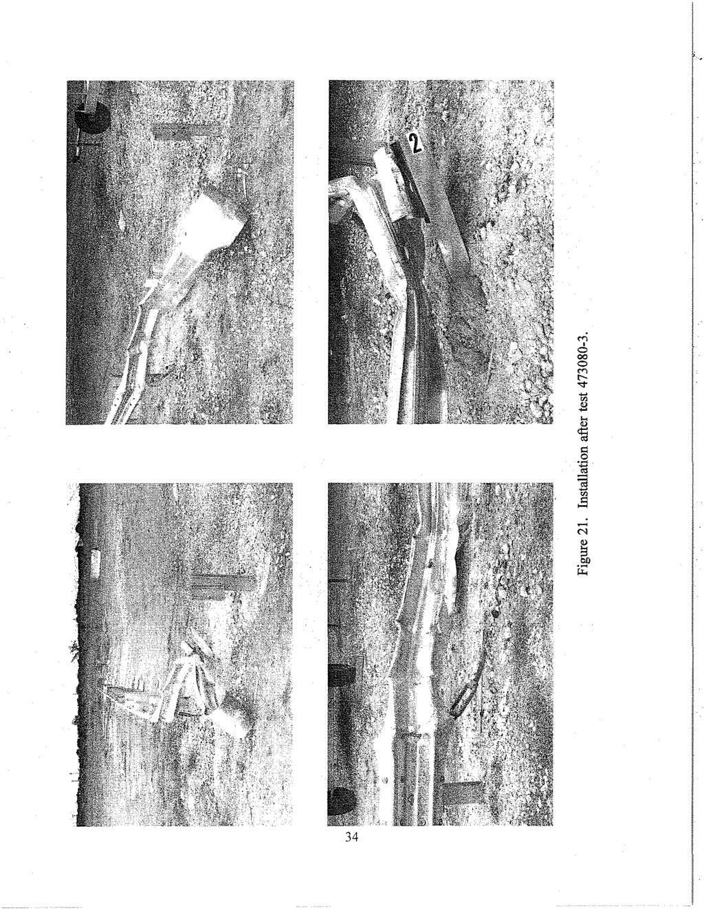
42 Test Description,. " The vehicle, traveling at kmh, impacted the terminal at a degree angle with the right quarter point of the vehicle aligned with the centerline of post 2. Shortly after impact the rail shows movement followed by movement at post 2. At s, post 1 starts to turn toward post 2. The vehicle's right front tire then impacts post 2 and deflates. The rail breaks away from the blockout at post 1 and post 1 snaps back into its original position at s. At s the vehicle impacts with the turnbuckle and the vehicle's rear tires lift off the ground. The vehicle moves backwards at 8.11 kmh. At s the rear tires comes back in contact with the ground. The vehicle continues moving backwards until coming to final rest 2.7 m from the face of the rail and at a 56.7 degree angle relative to tangent of the rail. Brakes on the vehicle were not applied. Sequential photographs of the test period are presented in appendix B, figures 38 and 39. Damage to Test nstallation Most of the damage to the terminal was near post 2, as shown in figures 20 and 21. Post 2 was pushed back 280 mm and laterally 20 mm. The guardrail mounting bolt pulled through the guardrail and backup plate, but remained on the post. Post 1 was disturbed, the blockout was twisted, the buffer end was off, and the bolt was still attached to the post and blockout. Post 3 was disturbed and the front flange on the blockout was twisted. The anchor rod was deformed downward and the turnbuckle was scraped. Vehicle Damage The vehicle sustained damage as shown in figure 22. The stabilizer bar, right and left front struts, fan, radiator, and right front axle received damage. The right front tire, wheel, and quarter panel were deformed. Both doors were jammed. Damage was also sustained to the hood, grill, bumper, and headlights. Maximum exterior crush to the vehicle was 270 mm at the top of the front bumper. Maximum occupant compartment deformation was 42 mm in the floor pan area. Exterior crush measurements and occupant compartment measurements are shown in appendix A, tables 9 and 10. Occupant Risk Values Data from the accelerometer located at the vehicle center-of-gravity were digitized for evaluation of occupant risk and were computed as follows. n the longitudinal direction, the occupant impact velocity was 11.3 mls at s, the highest O.OO-s occupant ridedown acceleration was g from to s, and the maximum s average acceleration g between and s. n the lateral direction, the occupant impact velocity was 3.34 mls at s, the highest s occupant ridedown acceleration was 32
43 , Figure 20. After impact trajectory for test
44 34 l '
45 Figure 22. Vehicle after test
46 2.48 g from to s,and the maximum s average was g between and s. These data and other pertinent information from the test are summarized in figure 23. Vehicle angular displacements are displayed in figure 44. Vehicular accelerations versus time traces are presented in figure 52 through 54. TEST (NCHRP Report 350 test no. 2-35) The installation was repaired, and a 1991 Chevrolet 2500 pickup, shown in figures 24 and 25, was used for the crash test. Test inertia weight of the vehicle was 2000 kg, and its gross static weight was 2000 kg. The height to the lower edge of the vehicle bumper was 465 mm and it was 686 mm to the upper edge of the bumper. Additional dimensions and information on the vehicle are given in appendix A, figure 33. The vehicle was directed into the installation using the cable reverse tow and guidance system, and was released to be freewheeling and unrestrained just prior to impact. Test Description The vehicle, traveling at km/h, impacted the terminal 0.05 m upstream of post 3 at an impact angle of degrees. Shortly following impact the vehicle begins to redirect. At and s, the vehicle is.at posts 4 and 5 respectively, becoming parallel to the rail at s. At this point the vehicle has slowed to km/h. The rear of the vehicle impacts the rail then exits at s, traveling km/h and at an degree angle. Brakes on the vehicle were applied at 2.1 s after impact, after the vehicle exited the installation. The vehicle's right front then contacts the post located third from the end and spins around approximately 180 degrees. The vehicle subsequently came to rest 14.0 m fr()m the end of the terminal and 7.3 m behind the installation. Sequential photographs are presented in appendix B, figures 40 and 41. Damage to Test nstallation There was minimal damage to the installation as shown in figures 26 and 27. The W-beam was deformed from post 3 through post 5. The vehicle was in contact with the rail for 4.34 m and then re-contacted the installation near the opposite end. Maximum permanent deformation was 40 mm at post 4. 36
47 0.000 s s s s 1905 mm post spacing (~ mrr!, offset 550t mm r w General nformation -...J Test Agency,...,... Test No.,, Date...,.. ".,.... Test Article Type.,.... Name.,...,.. nstallation Length (m) Size and/or dimension and material of key elements., Soil Type and Condition.... Test Vehicle Type.... Designation..,..,..,.., Model...,..,..,... Mass (kg) Curb..,..,... Test nertial.,.. Dummy.... Gross Static..,. Texas Transportation nstitute /09/97 Terminal Vermont G~ld 37.6 W beam guardrail on W150x14-steel posts with 1.47 m offset flare Standard soil,. dry Production 820C 1993 Ford Festiva mpact Conditions Speed km/h)..... Angle deg) Exit Conditions Speed km/h).... Angle deg) Occupant Risk Values mpact Velocity (mig) x-direction.... v-direction Ridedown Accelerations (g's) x'-direction ".... y-direction.... Max s Average (g's) x-direction _.. y-direction z-direction Test Article Deflections (m) Dynamic Permanent.... Vehicle Damage Exterior VDS.... CDC.... Maximum Exterior Vehicle Crush (mm)... nterior OCD.... Max. Dec. Com part. Deformation (mm) Post.. lmpact Behavior (during 1.0 s after impact) Max. Roll Angle (deg)... Max. Pitch Angle deg)... Max. Yaw Angle (deg)... N/A FD3 11 FDEW3 270 FS Figure 23. Summary of results for test

48 Figure 24. Vehicle/installation geometries for test
49 Figure 25. Vehicle before test
50 ; Figure 26. After impact trajectory for test
51 ...;-, M t-...;- '" $l... 'til " <: 0.~ 10 - ::;J rj -t- M ~ OJ) ~, 41
52 Vehicle Damage The vehicle received damage to exterior body panels only as shown in figure 28. This damage included the grill, bumper, right front and rear quarter panels and the door. Maximum exterior vehicle crush was 330 mm at the right front comer at bumper height. There was no deformation or intrusion of the occupant compartment. Exterior crush and occupant compartment measurements are shown in appendix A, tables 11 and 12. Occupant Risk Values Data from the accelerometer located at the vehicle center-of-gravity were digitized for evaluation of occupant risk and were computed as follows. n the longitudinal direction, the occupant impact velocity was 3.16 mlsat s, the highest s occupant ridedown acceleration was g from to to s, and the maximum s average acceleration was g between and s n the lateral direction, the occupant impact velocity was 3.80 mls at s, the highest s occupant ridedown acceleration was g from to to 0.275s, and the maximum s average was g between and s. These data and other pertinent information from the test are summarized in figure 29. Vehicle angular displacements are displayed in figure 45. Vehicular accelerations versus time traces are presented in figure 55 through
53 Figure 28. Vehicle after test
54 0.000 s s s s #"~ T 14.0 "' 1905 mm post spacing (~ =j r mrr offset "".~.~ r '<...,. '~'. 20.4SdOQ 550i mm i i!! i ij r, ~ u u ~ ~ t General nformation Test Agency..,...,.. Texas Transportation nstitute Test No Date... 11/05/97 Test Article Type.... Terminal Name"...,...,.... Vermont G-1 d nstallation Length (m) 37.6 Size and lor dimension and material of key W-beam guardrail on -W150x14 steel elements...,.... posts with 1.47 m offset flare Soil Type and Condition.... Standard'soil, dry Test Vehicle Type.... Production Designation P Model Chevrolet 2500 pickup Mass (kg) Curb...., Test nertial Dummy.... No dummy Gross Static mpact Conditions Speed (km/h).... Angle (deg).... Exit Conditions Speed (km/h).... Angle (deg).... Occupant Risk Values mpact Velocity (m/s) x-direction.,.... v-direction.... R.idedbwn Accelerations (g's) x-direction.... v-direction.... Max s Average (g's) x-direction.... v-direction z-direction Figure 29. Summary of results for test Test Article Deflections (m) Dvnamic Permanent Vehicle Damage Exterior VDS... 01RFQ2 CDC FREK2 & 01RDEW2 Maximum Exterior Vehicle Crush (mm) 330 nterior OCD!... FSOOOOOOO Max. Occ. Com part. Deformation (mm)... 0 Post-mpact Behavior (during 1.0 s after impact) Max. Roll Angle (deg) Max. Pitch Angle (deg) Max. Vaw Angle (deg) ~-~
55 V. SUMMARY OF FNDNGS AND CONCLUSONS SUMMARY OF FNDNGS The Vermont Agency of Transportation G-d W-Beam Terminal brought the vehicle to a controlled stop for test The vehicle gated through the terminal and came to a controlled stop behind the installation in test Damage sustained by the vehicle was considered moderate for both tests. There was no deformation of the occupant compartment for test 1 and test 2. The vehicle for test 3 came to a controlled stop after impacting the terminal at post 2. The vehicle sustained moderate damage and minimal occupant compartment deformation. The vehicle for test 4 was redirected at a safe angle and braked to a stop beyond the test installation. The vehicle sustained minimal damage and there was no occupant compartment deformation. For all tests there were no detached elements or debris to show potential for penetrating the occupant compartment or to present undue hazard to others in the area. The vehicle remained upright during and after the collision for all tests. There was no intrusion into adjacent traffic lanes caused by the vehicle trajectory. The occupant risk factors were well within the preferred limits specified in NCHRP Report 350 for tests 1, 2, and 4 and within the maximum required limits for test 3. CONCLUSONS The Vermont agency of Transportation G-d W-Beam Terminal met all the evaluation criteria set forth in NCHRP Report 350 for test designations 1-30,2-30, 3-34and 2-35 as shown in tables 1 thru 4. This testing is sufficient to meet the NCHRP 350 evaluation criteria for test level 2 terminals. 45!
56 _._--- ~ Table. Performance evaluation sununary for test , NCHRP Report 350 Test Test Agency: Texas Transportation nstitute Test No.: Test Date: 07/17/97 NCHRP Report 350 Evaluation Criteria Test Results Assessment Structural Adeguacx C. Acceptable test article performance may be by redirection, The Vermont G-l d Terminal stopped the vehicle controlled penetration, or controlled stopping of the vehicle. which came to rest adjacent to the rail. Occupant Risk D. Detached elements, fragments or other debris from the test There were no detached elements, fragments or article should not penetrate or show potential for penetrating debris to penetrate nor show potential for penetrating the occupant compartment, or present an undue hazard to the occupant compartment or to present undue hazard other traffic, pedestrians, or personnel in a work zone. to others in the area. There was no deformation or Pass Deformations of, or intrusions into, the occupant intrusion into the occupant compartment. compartment that could cause serious injuries should not be pennitted. G. t is preferable, although not essential, that the vehicle The vehicle remained upright during and after the remain upright during and after collision. collision. Pass H. Occupant impact velocities should satisfy the following: Occupant Velocity Limits (m/s) Component Preferred Maximum Longitudinal and lateral 9 12 Longitudinal occupant impact velocity = 8.46 mls Lateral occupant impact velocity = 1.37 mls. Occupant ridedown accelerations should satisfy the following: Occupant Ridedown Acceleration Limits (g's) Longitudinal ridedown acceleration = g Pass Lateral ridedown acceleration = g Component Preferred Maximum Pass Pass Longitudinal and lateral '. Vehicle Trajectorx K. After collision it is preferable that the vehicle's trajectory The vehicle did not intrude into adjacent traffic not intrude into adjacent traffic lanes. lanes. N. Vehicle trajectory behind the test article is acceptable. The vehicle came to a stop adjacent to the front face of the rail. Pass N/A
57 - - -.) "'" Table 2. Performance evaluation summary for test , NCHRP Report 350 Test Test Agency: Texas Transportation nstitute Test No.: ~ ~ Test Date: 08114/97 Structural Adeguacx NCHRP Report 350 Evaluation Criteria Test Results Assessment C. Acceptabletest article performance may be by redirection, The Vermont G-td Terminal allowed the vehicle to controlled penetration, or controlled stopping of the vehicle. gate through and the vehicle came to rest behind the Pass installation. Occupant Risk D. Detached elements, fragments or other debris from the test There were no detached elements, fragments or debris article should not penetrate or show potential for penetrating to penetrate nor show potential for penetrating the the occupant compartment, or present an undue hazard to occupant compartment or to present undue hazard to other traffic, pedestrians, or personnel in a work zone. others in the area. There was no deformation or Pass Deformations of, or intrusions into, the occupant intrusion into the occupant compartment. compartment that could cause serious injuries should not be permitted. F. The vehicle should remain upright during and after collision The vehicle remained upright during and after the although moderate roll, pitching and yawing are acceptable. collision. Pass H. Occupant impact velocities should satisfy the following: Occupant Velocity Limits (m/s) Longitudinal occupant impact velocity = 5.38 mls There was no occupant contact in the lateral direction. Pass Component Preferred Maximum Longitudinal and lateral Occupant ridedown accelerations should satisfy the, following: Occupant Ridedown Acceleration Limits (g's) Component Preferred Maximum Longitudinal and lateral S 20 Vehicle Trajectorx Longitudinal ridedown acceleration = g No contact in lateral direction. K. After collision it is preferable that the vehicle's tr1!iectory not The vehicle did not intrude into adjacent traffic lanes. intrude into adjacent traffic lanes. N. Vehicle traiectorv behind the test article is acceptable. The vehicle came to rest behind the installation. Pass Pass Pass.
58 Table 3. Performance evaluation summary for test , NCHRP Report 350 Test Test Agency: Texas Transportation nstitute Test No.: Test Date: 09/09/97 NCHRP Report 350 Evaluation Criteria Test Results Assessment Structural Adeguac)(.j>. 00 C. Acceptable test article performance may be by redirection, controlled penetration, or controlled stopping of the vehicle. Occupant Risk D. Detached elements, fragments or other debris from the test article should not penetrate or show potential for penetrating the occupant compartment, or present an undue hazard to other traffic, pedestrians, or personnel in a work zone. Deformations of, or intrusions into, the occupant compartment that could cause serious injuries should not be permitted. F. The vehicle should remain upright during and after collision although moderate roll, pitching and yawing are acceptable. H. Occupant impact velocities should satisfy the following: Occupant Velocity Limits (m/s) Component Preferred Maximum The Vermont G-d Terminal brought the vehicle to a.. stop adjacent to the rail. There were no detached elements, fragments or debris to penetrate nor show potential for penetrating the occupant compartment or to present undue hazard to others in the area. Maximum deformation into the occupant compartment was 42 mm in the firewalllfloor pan and are judged to not cause serious injury. The vehicle remained upright during and after the collision. Longitudinal occupant impact velocity = mls Lateral occupant impact velocity = 3.34 mls Pass Pass Pass Pass Longitudinal and lateral Occupant ridedown accelerations should satisfy the following: Occupant Ridedown Acceleration Limits (g's) Component Preferred Maximum Longitudinal and lateral Longitudinal ridedown acceleration = g Lateral ridedown acceleration = 2.48 g Pass Vehicle Trajector)( K. After collision it is preferable that the vehicle's trajectory not intrude into adjacent traffic lanes. The vehicle did not intrude into adjacent traffic lanes. Pass N. Vehicle trajectory behind the test article is acceptable... The vehicle came to rest adjacent to the front face of the rail. N/A,~-~-".~ ~..-~.~-.
59 Table 4. Perfonnance evaluation summary for test , NCHRP Report 350 Test Test Agency: Texas Transportation nstitute Test No.: Test Date: 10/16/97 NCHRP Report 350 Evaluation Criteria Test Results Assessment Structural Adequacy A. Test article should contain and redirect the vehicle; The Vermont G-d Terminal redirected the the vehicle should not penetrate, uoderride, or vehicle. The vehicle did not penetrate, uoderride, override the installation although controlled lateral or override the installation. deflection of the test article is acceptable. Pass..,. 'D Occupant Risk D. Detached elements, fragments or other debris from the There were no detached elements, fragments or test article should not penetrate or show potential for debris to penetrate nor show potential for penetrating the occupant compartment, or present an penetrating the occupant compartment or to present uodue hazard to other traffic, pedestrians, or personnel uodue hazard to others in the area. There was no Pass in a work zone. Defonnations of, or intrusions into, defonnation or intrusion into the occupant the occupant compartment that could cause serious compartment. injuries should not be pennitted. F. The vehicle should remain upright during and after The vehicle remained upright during and after the collision although moderate roll, pitching and yawing collision. Pass are acceptable. Vehicle Trajectory K. After collision it is preferable that the vehicle's The vehicle did not intrude into adjacent traffic trajectory not intrude into adjacent traffic lanes. lanes. Pass L. The occupant impact velocity in the longitudinal Longitudinal occupant impact velocity was direction should not exceed 12 mls and the occupant 3.16 mls and longitudinal occupant ridedown ridedown acceleration in the longitudinal direction acceleration was g. Pass should not exceed 20 g's. M. The exit angle from the test article preferably should The exit angle of degrees was 57 percent of be less than 60 percent oftest impact angle, measured the impact angle. Pass at time of vehicle loss of contact with test device. ~.-.. ~~~. '-"~"--~----,--
60
61 i APPENDX A. VEDCLE PROPERTES This section provides additional dimensions and information on vehicles used for the crash tests performed under this study. 51
62 l\h DATE, Z/1Z/9Z TEST NO.' ~N ND.,2C1 MR n01make'_-'g>je:jo"- MODEl: M ERQ YEAR 1990 ODOMETER; TiRE SZE- 155 R12 TRE NFlATON PRESSUR['c' 1st Use:_ 2nd or More Use:L Minor Damage Charged to Projed: MASS DSTRBUTON (kg) LF_~2,"2,,-Z<-_ RF_~2'"'4±l0" LR LlZLJ8"---_ RR --"luzc;5l-_ DESCRBE ANY DAMAGE TO VEHCLE PROR TO TEST: /\ ACC:~MrnRS N WfjEEL i-r '''''' -L::J \\ -P<: f-i llre DA--,- ~EEL OiA c- d 'n cc \ '+' " }-- TEST NERTAL C.M. (~~ <t VEHCl 1 WHEEL lmck ENGNE TYPE' 3 CY ENGNE CD: :0L.LJ..! TRANSMSSON lype: _ AUTO!L MANUAL OPTONAL EQUPMENT: l~ ~ '-' \\ \ " ~ ff; rr'-'i -,-, -,, E- M, M,," t, f ; 0 DUMMY DATA: TYPE: 50th percentilg mqle MASS: 76 kg SEAT PQSTON:.JDld"",veL' GEOMETRY - (mm) A 1420 E 640 J 680 N B 730 F 3645 K c 2225 G 91.6 L Z50 p D 1340 H M TEST MASS - (kg) CURB NERTAL M, Z M, M, Z R 1340 s 535 T 330 u GROSS STATC , Figure 30. Vehicle properties for test
63 Table 5. Exterior crush measurements for test \. VEHCLE CRUSH MEASUREMENT SHEET 1 Complete When Applicable End Damage Side Damage Undefonned end width Bowing: B -- Xl -- Comer shift: A End shift at frame (CDC) (check one) A2 B Bowing constant Xl +X2 < 4 inches --- > 4 inches 2 X2 -- Note: Measure Cl to C6 from Driver to Passenger side in Front or Rear impacts Rear to Front in Side impacts. Direct Damage Specific mpact Plane* of Width ** Max*** Field Nwnber C-Measurements (CDC) Crush L" C, C, C, C, C, C, ±D 1 Front bumper 'Table taken from National Accident Sampling System (NASS). *dentify the plane at which the C-measurements are taken (e.g., at bumper, above bumper, at sill, above sil, at beltline, etc.) or label adjustments (e.g., free space). Free space value is defined as the distance between the baseline and the original body contour taken at the individual C locations. This may include the following: bumper lead, bumper taper, side protrusion, side taper, etc. Record the value for each C-measurement and maximum crush. **Measure and document on the vehicle diagram the beginning or end of the direct damage width and field L (e.g., side damage with respect to undamaged axle). ***Measure and document on the vehicle diagram the location of the maximum crush. Note: Use as many lines/columns as necessary to describe each damage profile. 53
64 Table 6. Occupant compartment deformation for test Occupant Compartment Deformation BEFORE AFTER ((f ~, P H 1'Q, 'fin F : G dj G l t:----- JjJ' \v ~ BB. B ::;::;:-... ( ) \,--C'-l LJ LJ A1 A2 A3 B1 B2 B3 B4 B5 B6 B7 B8 B9 C1 C2 C3 D1 D2 D3 E1 E2 F G H ~--- 54
65 DATE, 8/14/97 MODEL: EESTVA TRE NFLATON PRESSURE.~ TEST NO." ~N No,KN,P06HOM w<" FORD YEAR, 1,,9,,9o..1L- ODOMETER: ",3",5"1.. 9,,,4,- TRE SZE 1 55 R 1 2 1st Use 2nd or More Use:~ Minor Domoge Charged to Project:--"X'--- MASS DlSTR8UTON (kg),,_~2..,6,,-1l---_ RF_~2'-'4t.i9'-_ LR L1 6"'4"---_ RR --"l'-'4,,6'-_ DESCR8E ANY DAMAGE TO VEHCLE PROR TO TEST: ~ N:.CElLROMrr R.S note: ::J N WHEEL. ~ ''''''' 't' K::J \ TRE DA--,- WHEEL DA- roc- - U \~ i " ~ ~ -,-, -, c N, 0, n \\ Y?f " 1'No 't' }- TEST NERTAL C.f.!. [~~.~ rm ' N,,- q; VEHCLE 1 WHEEL r~', ;, 0 ENGNE TYPE- 4 Cyt ENGNE cd:-11~3,ll TRANSMSSON TYPE: _ AUTO ~ MANUAL OPTONAL EQUPMENT: DUMMY DATA: lype: 50th nercentile mq!@ MASS: 76 kn SEAT POSTON:.cP"'riv"'"''-- GEOMETRY - (mm) A 600 E 550 B 650 F 3480 c 2280 G H 770 N K 530 L 86 p N 345 Q 1420 R s T u 2370 MASS - (kg) CURB M, 535 M, 291 MT 826 TEST NERTAL GROSS STATC Figure 31. Vehicle properties for test
66 Table 7. Exterior vehicle crush measurements for test f VEHCLE CRUSH MEASUREMENT SHEET' Complete When Applicable End Damage Side Damage Undefonned end width Bowing: B -- Xl -- Comer shift: Al A2 - B2 -- End shift at frame (CDC) Bowing constant (check one) Xl + X2 < 4 inches = > 4 inches X2 -- Note: Measure Cl to C6 from Driver to Passenger side in Front or Rear impacts Rear to Front in Side impacts. Direct Damage Specific mpact Plane* of Width ** Max*** Field Number C~Measurements (CDC) Crush L" C, C, C, C, C, C, ±D 1 Top affront bumper 'Table taken from National Accident Sampling System (NASS). *dentify the plane at which the C-measurements are taken (e.g., at bumper, above bumper, at sill, above sill, at beltline, etc.) or label adjustments (e.g. free space). Free space value is defined as the distance between the baseline and the original body contour taken at the individual C locations. This may include the following: bumper lead, bumper taper, side protrusion, side taper, etc. Record the value for each C-measurement and maximum crush. **Measure and document on the vehicle diagram the beginning or end of the direct damage width and field L (e.g., side damage with respect to undamaged axle). ***Measure and document on the vehicle diagram the location of the maximum crush. Note: Use as many lines/columns as necessary to describe each damage profile. 56
67 Table 8. Occupant compartment deformation for test Occupant Compartment Deformation BEFORE AFTER ((r ~ )~ 'RQ F : G djg l t.:----- Jjf \v ~ A1 A2 A3 B1 B B B4 B5 B ( \,-Tr-l LJ LJ B7 B8 B9 C1 C2 C E1 E2 F G H
68 DATEo 9/19 (97 TEST NO ~N ND.,KNJPOSHXP61286S7MAKE, FORD MODEL: FESTl VA TRE NFLATON PRESSURE'~ YEAR: 1993 ODOMETER: TRE SZE- 155 R12 1st Use:_ 2nd or More Use:~ Minor Domage Charged to Project: ~_ MASS DSTR8UTON (kg) LF_~2"",6,,,3,,----_ RF.. 2-"5,,,2~_ lr 1... S"'6"----_ RR --'-l 4",,9 DESCRBE ANY DAMAGE TO VEHCLE PROR TO TEST: SOME DAMAGE TO ROOF N WHEEL ""'" ~ ""L~ TRE DA- 1--'- ~c 1'\ note: """''''co" / \' «71 ~ \ ( ::.. R-170mm TO LT \\1, 't' )-- TEST NERTlAL C.M.,- C- D 'n ~~~ l-s.: ~ ~ F::~ tm " \\\ ~ WHEEL 01A T-, -,, E-., M. 0 M, q:., vthcle 1 WHEEL r"", ~ ; 0 ENGNE TYPE- 4 CY ENGNE CD;--L]~3,,----1L- TRANSMSSON TYPE: _AuTO ~ MANUAL OPTONAL EQUPMENT: DUMMY DATA: lype: 50th percentile mole MASS: 76 kg SEAT POSTON:~Omri~ye,,-, GEOMETRY - (mm) A 1500 E S N B 640 F 3505 K c 2295 G l 115 p H M 380 Q 1390 R s SOO S u 2400 TEST MASS - (kg) CURB NERTAL M, 525 5]5 M, 28Q ;3Q5 MT 8Q5 82Q GROSS STATC t.\nporh\47308o\wlkptpj.dwg Figure 32. Vehicle properties for test
69 Table 9. Exterior vehicle crush measurements for test VEHCLE CRUSH MEASUREMENT SHEET 1 Complete When Applicable End Damage Side Damage Undeformed end width Bowing: B -- X -- Comer shift: Al End shift at frame (CDC) (check one) A2 B Bowing constant Xl + X2 < 4 inches ---- > 4 inches 2 X2 -- Note: Measure Cl to C6 from Driver to Passenger side in Front or Rear impacts Rear to Front in Side impacts. Direct Damage Specific mpact Plane* of Width ** Max*** Field Number C-Measurements (CDC) Crush L" C, C, c, c, c, C, ±D 1 Top front bumper 'Table taken from National Accident Sampling System (NASS). *dentify the plane at which the C-measurements are taken (e.g., at bumper, above bumper, at sill, above sill, at beltline, etc.) or label adjustments (e.g., free space). Free space value is defined as the distance between the baseline and the original body contour taken at the individual C locations. This may include the following: bumper lead, bumper taper, side protrusion, side taper, etc. Record the value for each C-measurement and maximum crush. **Measure and document on the vehicle diagram the beginning or end of the direct damage width and field L (e.g., side damage with respect to undamaged axle). ***Measure and document on the vehicle diagram the location of the maximum crush. Note: Use as many lines/columns as necessary to describe each damage profile. 59
70 ;" Table 10. Occupant compartment deformation for test Occupant Compartment Deformation BEFORE AFTER ((f ~, P H 1)1 'H~ F : G djg t.:----- Jj) ~ ~ ( \,--YF-l LJ LJ A1 A2 A3 B1 B2 B3 B4 B5 B6 B7 B8 B9 C1 C2 C3 D1 D2 03 E1 E2 F G H
71 DATE, -'..1,-1 _-",5_-~9,-,7 TEST NO.' -"4!...7"'3"'0"'8"'0_-,,4=---- VN No.,_1,..,G"'C"'G"'C'-'2"4"Z"'5"'M,,E..,1-"'5"'9,,4"'68"-- YEAR, -'..1 9,,-9,,-,-1 TRE NFlATON PRESSURE: "A(, _--"C!:!Hs,:EV:!..R!;:O><.L~EO!T' MOO'l, -=2"'5"'0"'0--'-'P L "u=---- OOOMETER,_-'2... 1,,2~0"_7,,9':! TlR' SlZE"--,L",T,---,2",4",5,-,7-,,5,,,R,..,1..,,6,-_ MASS DSTRBUTON (kg) LF 548 RF_--"5,,,3,,6 lr 4",6,,-7,- RR_-"4,,,4,,9 DESCRBE ANY DAMAGE TO VEHCLE PROR TO TEST; [ "~~ TRE ,- Wl1EEL r1 - [!.= ~ r' - " f-rn== '-----' '\:- c- ~ ~ //l V C"/ b -,. M,,, F _._--.. '" >- ~ mr '""'''' '" kw)t 1 M,,-. VEKCLE T [ ' i WHEEl """ Denotes accelerometer location. NOTES: REAR ACC S 60mro TO! T OF C ENGNE lype- ENGNE CD: 8 CYL. 5.7 L TRANSMSSON TYPE: X AUTO OPTONAL ECUPMENT: DUMMY OATA: _ MANUAL ryp" MASS: SEAT POSTON: i GEOMETRY - (mm) A 1850, F 5450 c 3355 G H MASS - (kg) CURB N K p " TEST NERTAL R S r u GROSS STATC M, 1119 M, 838 Mr Figure 33. Vehicle properties for test
72 Table 11. Exterior vehicle crush measurements for test i' VEHCLE CRUSH MEASUREMENT SHEET' Complete When Applicable End Damage Side Damage Undeformed end width Bowing: Bl -- X -- Comer shift: A A2 B X2 -- End shift at frame (CDC) (check one) Bowing constant < 4 inches Xl + X2 :--- > 4 inches 2 Note: Measure C to C6 from Driver to Passenger side in Front or Rear impacts Rear to Front in Side impacts. Specific Direct Damage C, C, C, mpact Plane'" of Width ** Max*** Field Number C-Measurements (CDC) Crush L", Top of front bumper C, C, C, ±D mm above ground N/A 35 (Rear fender well) 0 40 '70 0 'Table taken from National Accident Sampling System (NASS). *dentify the plane at which the C-measurements are taken (e.g., at bumper, above bumper, at sill, above sill, at beltline, etc.) or label adjustments (e.g., free space). Free space value is defined as the distance between the baseline and the original body contour taken at the individual C locations. This may include the following: bumper lead, bumper taper, side protrusion, side taper, etc. Record the value for each C-measurement and maximum crush. **Measure and document on the vehicle diagram the beginning or end of the direct damage width and field L (e.g., side damage with respect to undamaged axle). ***Measure and document on the vehic~e diagram the location of the maximum crush. Note: Use as many lines/columns as necessary to describe each damage profile. 62
73 ~ Table 12. Occupant compartment deformation for test Occupant Compartment Deformation r--'~~~~--, \.! cd \ G\\ \ / \1 L ~r:=:j1 L BEFORE AFTER A A A B B B //. l C ,-- ~~ Al.2'3 il - - C ,...-1 j i J ~~ 2&.3 i U(--\]., CL2&3-i C ,...LJ ~'-.// ~-T-r\ ~ " E E ( Bl B2 _ B3 11 F Elt~1 G /~ ~ " \7-, H U LJ
74 ,
75 APPENDX B. SEQUENTAL PHOTOGRAPHS This section contains photographs taken from high speed film during the test sequence of the crash tests performed under this study. 65

76 0.000 s s s s Figure 34. Sequential photographs for test (overhead and frontal views). 66
77 0.177 s s s, s Figure 34. Sequential photographs for test (overhead and frontal views) (continued). 67
78 0.000 s s s s s s s s Figure 35. Sequential photographs for test (rear view). 68 1
79 0.000 s s, s s Figure 36. Sequential photographs for test (overhead and frontal views). 69
80 i s s s s Figure 36. Sequential photographs for test (overhead and frontal views) (continued). 70
81 0.000 s s s s s s i, s s Figure 37. Sequential photographs for test (rear view). 71
82 0.000 s s s s Figure 38. Sequential photographs for test (overhead and frontal views). 72
83 i s s r s s Figure 38. Sequential photographs for test (overhead and frontal views) (continued). 73
84 0.000 s s s s, s s s s Figure 39. Sequential photographs for test (rear view). 74
85 0.000 s s s s Figure 40. Sequential photographs for test (overhead and frontal views). 75
86 0.355 s s s s Figure 40. Sequential photographs for test (overhead and frontal views) (continued). 76

87 i s s s s s s s s Figure 41. Sequential photographs for test (rear view). 77
NCHRP Report 350 Test 4-12 of the Modified Thrie Beam Guardrail
 NCHRP Report 350 Test 4-12 of the Modified Thrie Beam Guardrail PUBLICATION NO. FHWA-RD-99-065 DECEMBER 1999 Research, Development, and Technology Turner-Fairbank Highway Research Center 6300 Georgetown
TEXAS TRANSPORTATION INSTITUTE THE TEXAS A & M UNIVERSITY SYSTEM COLLEGE STATION, TEXAS 77843
 NCHRP REPORT 350 ASSESSMENT OF EXISTING ROADSIDE SAFETY HARDWARE by C. Eugene Buth, P.E. Senior Research Engineer Wanda L. Menges Associate Research Specialist and Sandra K. Schoeneman Research Associate
GUARDRAIL TESTING MODIFIED ECCENTRIC LOADER TERMINAL (MELT) AT NCHRP 350 TL-2. Dean C. Alberson, Wanda L. Menges, and Rebecca R.
 AT NCHRP 350 TL-2. Dean C. Alberson, Wanda L. Menges, and Rebecca R.") GUARDRAIL TESTING MODIFIED ECCENTRIC LOADER TERMINAL (MELT) AT NCHRP 350 TL-2 Dean C. Alberson, Wanda L. Menges, and Rebecca R. Haug Prepared for The New England Transportation Consortium July 2002 NETCR
GUARDRAIL TESTING MODIFIED ECCENTRIC LOADER TERMINAL (MELT) AT NCHRP 350 TL-2 Dean C. Alberson, Wanda L. Menges, and Rebecca R. Haug Prepared for The New England Transportation Consortium July 2002 NETCR
TEXAS TRANSPORTATION INSTITUTE THE TEXAS A & M UNIVERSITY SYSTEM COLLEGE STATION, TEXAS 77843
 NCHRP REPORT 350 TEST 3-11 OF THE STEEL-BACKED TIMBER GUARDRAIL by D. Lance Bullard, Jr., P.E. Associate Research Engineer Wanda L. Menges Associate Research Specialist and Sandra K. Schoeneman Research
TEXAS TRANSPORTATION INSTITUTE THE TEXAS A & M UNIVERSITY SYSTEM COLLEGE STATION, TEXAS
 NCHRP REPORT 350 TEST 4-21 OF THE ALASKA MULTI-STATE BRIDGE RAIL THRIE-BEAM TRANSITION by C. Eugene Buth Senior Research Engineer William F. Williams Assistant Research Engineer Wanda L. Menges Associate
NCHRP REPORT 350 TEST 4-12 OF THE MASSACHUSETTS S3-TL4 STEEL BRIDGE RAILING MOUNTED ON CURB AND SIDEWALK
 TEXAS TRANSPORTATION INSTITUTE NCHRP REPORT 350 TEST 4-12 OF THE MASSACHUSETTS S3-TL4 STEEL BRIDGE RAILING MOUNTED ON CURB AND SIDEWALK by C. Eugene Buth Research Engineer and Wanda L. Menges Associate
TEXAS TRANSPORTATION INSTITUTE THE TEXAS A & M UNIVERSITY SYSTEM COLLEGE STATION, TEXAS 77843
 NCHRP REPORT 350 TEST 3-11 OF THE NEW YORK DOT PORTABLE CONCRETE BARRIER WITH I-BEAM CONNECTION (RETEST) by Roger P. Bligh, P.E. Assistant Research Engineer Wanda L. Menges Associate Research Specialist
Form DOT F (8-72) Texas Transportation Institute The Texas A&M University System College Station, Texas
 Texas Transportation Institute The Texas A&M University System College Station, Texas") 1. Report No. FHWA/TX-02/4162-1 Technical Report Documentation Page 2. Government Accession No. 3. Recipient's Catalog No. 4. Title and Subtitle EVALUATION OF TEXAS GRID-SLOT PORTABLE CONCRETE BARRIER
1. Report No. FHWA/TX-02/4162-1 Technical Report Documentation Page 2. Government Accession No. 3. Recipient's Catalog No. 4. Title and Subtitle EVALUATION OF TEXAS GRID-SLOT PORTABLE CONCRETE BARRIER
CRASH TEST AND EVALUATION OF 3-FT MOUNTING HEIGHT SIGN SUPPORT SYSTEM
 TTI: 9-1002-15 CRASH TEST AND EVALUATION OF 3-FT MOUNTING HEIGHT SIGN SUPPORT SYSTEM ISO 17025 Laboratory Testing Certificate # 2821.01 Crash testing performed at: TTI Proving Ground 3100 SH 47, Building
NCHRP Report 350 Crash Testing and Evaluation of the S-Square Mailbox System
 TTI: 0-5210 NCHRP Report 350 Crash Testing and Evaluation of the S-Square Mailbox System ISO 17025 Laboratory Testing Certificate # 2821.01 Crash testing performed at: TTI Proving Ground 3100 SH 47, Building
Texas Transportation Institute The Texas A&M University System College Station, Texas
 1. Report No. FHWA/TX-05/9-8132-P7 4. Title and Subtitle TL-4 CRASH TESTING OF THE F411 BRIDGE RAIL 2. Government Accession No. 3. Recipient's Catalog No. 5. Report Date October 2004 Technical Report Documentation
MASH08 TEST 3-11 OF THE ROCKINGHAM PRECAST CONCRETE BARRIER
 Proving Ground Report No. 400001-RPC4 Report Date: July 2009 MASH08 TEST 3-11 OF THE ROCKINGHAM PRECAST CONCRETE BARRIER by C. Eugene Buth, P.E. Research Engineer William F. Williams, P.E. Assistant Research
February 8, In Reply Refer To: HSSD/CC-104
 February 8, 2008 200 New Jersey Avenue, SE. Washington, DC 20590 In Reply Refer To: HSSD/CC-04 Barry D. Stephens, P.E. Sr. Vice President Engineering Energy Absorption Systems, Inc. 367 Cincinnati Avenue
MASH Test 3-11 on the T131RC Bridge Rail
 TTI: 9-1002-12 MASH Test 3-11 on the T131RC Bridge Rail ISO 17025 Laboratory Testing Certificate # 2821.01 Crash testing performed at: TTI Proving Ground 3100 SH 47, Building 7091 Bryan, TX 77807 Test
STI Project: Barrier Systems, Inc. RTS-QMB Longitudinal Barrier. Page 38 of 40 QBOR1. Appendix F (Continued) Figure F-3
 Figure F-3") Barrier Systems, Inc. RTS-QMB Longitudinal Barrier STI Project: QBOR1 Page 38 of 40 Appendix F (Continued) Figure F-3 t=.500sec 115 meters overall 37.1 Impact Severity (kj).. 141.6 Angle (deg).. 25 Speed
Barrier Systems, Inc. RTS-QMB Longitudinal Barrier STI Project: QBOR1 Page 38 of 40 Appendix F (Continued) Figure F-3 t=.500sec 115 meters overall 37.1 Impact Severity (kj).. 141.6 Angle (deg).. 25 Speed
MASH TEST 3-37 OF THE TxDOT 31-INCH W-BEAM DOWNSTREAM ANCHOR TERMINAL
 TTI: 9-1002 MASH TEST 3-37 OF THE TxDOT 31-INCH W-BEAM DOWNSTREAM ANCHOR TERMINAL ISO 17025 Laboratory Testing Certificate # 2821.01 Crash testing performed at: TTI Proving Ground 3100 SH 47, Building
A MASH Compliant W-Beam Median Guardrail System
 0 0 0 0 0 A MASH Compliant W-Beam Median Guardrail System By A. Y. Abu-Odeh, R. P. Bligh, W. Odell, A. Meza, and W. L. Menges Submitted: July 0, 0 Word Count:, + ( figures + tables=,000) =, words Authors:
VULCAN BARRIER TL-3 GENERAL SPECIFICATIONS
 VULCAN BARRIER TL-3 GENERAL SPECIFICATIONS I. GENERAL A. The VULCAN BARRIER TL-3 (VULCAN TL-3) shall be a highly portable and crashworthy longitudinal barrier especially suited for use as a temporary barrier
TEXAS TRANSPORTATION INSTITUTE THE TEXAS A & M UNIVERSITY SYSTEM COLLEGE STATION, TEXAS
 TEXAS TRANSPORTATION INSTITUTE Test Level 2 Evaluation of the RENCO Ren-Gard 815 Truck Mounted Attenuator by C. Eugene Buth Senior Research Engineer and Wanda L. Menges Associate Research Specialist Contract
VERIFICATION & VALIDATION REPORT of MGS Barrier Impact with 1100C Vehicle Using Toyota Yaris Coarse FE Model
 VERIFICATION & VALIDATION REPORT of MGS Barrier Impact with 1100C Vehicle Using Toyota Yaris Coarse FE Model CCSA VALIDATION/VERIFICATION REPORT Page 1 of 4 Project: CCSA Longitudinal Barriers on Curved,
Evaluation and Design of ODOT s Type 5 Guardrail with Tubular Backup
 Evaluation and Design of ODOT s Type 5 Guardrail with Tubular Backup Draft Final Report Chuck A. Plaxico, Ph.D. James C. Kennedy, Jr., Ph.D. Charles R. Miele, P.E. for the Ohio Department of Transportation
Universal TAU-IIR Redirective, Non-Gating, Crash Cushion
 TB 110927 Rev. 0 Page 1 of 5 Product Specification Universal TAU-IIR Redirective, Non-Gating, Crash Cushion I. General The Universal TAU-IIR system is a Redirective, Non-Gating Crash Cushion in accordance
EVALUATION OF THE CRASH PERFORMANCE OF TRIPLE STEEL U-CHANNEL SIGN SUPPORT INSTALLATIONS IN STRONG SOIL
 EVALUATON OF THE CRASH PERFORMANCE OF TRPLE STEEL U-CHANNEL SGN SUPPORT NSTALLATONS N STRONG SOL Prepared for The Marion Steel Company 912 Cheney Ave. Marion, OH 4332 Prepared by Dean C. Alberson, P.E.
Virginia Department of Transportation
 TEST REPORT FOR: Virginia Department of Transportation SKT SP 350 50 (15.24 m) System PREPARED FOR: Virginia Department of Transportation 1401 E. Broad St. Richmond, VA 23219 TEST REPORT NUMBER: REPORT
Product Specification. ABSORB 350 TM TL-2 Non-Redirective, Gating, Crash Cushion Applied to Quickchange Moveable Barrier
 TB 000612 Rev. 0 Page 1 of 9 Product Specification ABSORB 350 TM TL-2 Non-Redirective, Gating, Crash Cushion Applied to Quickchange Moveable Barrier I. General The ABSORB 350 TM TL-2 System is a Non-Redirective,
Transportation Institute
 .JIIIIIII"" Texas Transportation Institute SUMMARY OF TESTING ON 'l'he RENCO TRUCK MOUNTED ATTENUATOR by Wanda L. Menges Associate Research Specialist C. Eugene Buth, P.E. Senior Research Engineer and
Texas Transportation Institute The Texas A&M University System College Station, Texas
 1. Report No. FHWA/TX-07/0-5527-1 4. Title and Subtitle DEVELOPMENT OF A LOW-PROFILE TO F-SHAPE TRANSITION BARRIER SEGMENT 2. Government Accession No. 3. Recipient's Catalog No. Technical Report Documentation
MASH TEST 3-11 OF THE TxDOT T222 BRIDGE RAIL
 TTI: 9-1002-12 MASH TEST 3-11 OF THE TxDOT T222 BRIDGE RAIL ISO 17025 Laboratory Testing Certificate # 2821.01 Crash testing performed at: TTI Proving Ground 3100 SH 47, Building 7091 Bryan, TX 77807 Test
Manual for Assessing Safety Hardware
 American Association of State Highway and Transportation Officials Manual for Assessing Safety Hardware 2009 vii PREFACE Effective traffic barrier systems, end treatments, crash cushions, breakaway devices,
VULCAN BARRIER TL-3 GENERAL SPECIFICATIONS
 VULCAN BARRIER TL-3 GENERAL SPECIFICATIONS I. GENERAL A. The VULCAN BARRIER TL-3 (VULCAN TL-3) shall be a highly portable and crashworthy longitudinal barrier especially suited for use as a temporary barrier
July 10, Refer to: HSA-10/CC-78A
 July 10, 2003 Refer to: HSA-10/CC-78A Barry D. Stephens, P.E. Senior Vice President of Engineering ENERGY ABSORPTION Systems, Inc. 3617 Cincinnati Avenue Rocklin, California 95765 Dear Mr. Stephens: Your
MASH TEST 3-11 OF THE TxDOT SINGLE SLOPE BRIDGE RAIL (TYPE SSTR) ON PAN-FORMED BRIDGE DECK
 ON PAN-FORMED BRIDGE DECK") TTI: 9-1002 MASH TEST 3-11 OF THE TxDOT SINGLE SLOPE BRIDGE RAIL (TYPE SSTR) ON PAN-FORMED BRIDGE DECK ISO 17025 Laboratory Testing Certificate # 2821.01 Crash testing performed at: TTI Proving Ground
TTI: 9-1002 MASH TEST 3-11 OF THE TxDOT SINGLE SLOPE BRIDGE RAIL (TYPE SSTR) ON PAN-FORMED BRIDGE DECK ISO 17025 Laboratory Testing Certificate # 2821.01 Crash testing performed at: TTI Proving Ground
14. Sponsoring Agency Code McLean, Virginia
 TECHNICAL REPORT DOCUMENTATION PAGE I. Report No. 2. Government Accession No. FHWA-RD-93-069 4. Title and Subtitle TESTING OF NEW BRIDGE RAIL AND TRANSITION DESIGNS Volume XII: Appendix K Oregon Transition
Texas Transportation Institute The Texas A&M University System College Station, Texas
 2. Government Accession No. 3. Recipient's Catalog No. 1. Report No. FHWA/TX-03/0-4138-3 4. Title and Subtitle PERFORMANCE OF THE TXDOT T202 (MOD) BRIDGE RAIL REINFORCED WITH FIBER REINFORCED POLYMER BARS
CRASH TEST AND EVALUATION OF TEMPORARY WOOD SIGN SUPPORT SYSTEM FOR LARGE GUIDE SIGNS
 TTI: 9-1002-15 CRASH TEST AND EVALUATION OF TEMPORARY WOOD SIGN SUPPORT SYSTEM FOR LARGE GUIDE SIGNS ISO 17025 Laboratory Testing Certificate # 2821.01 Crash testing performed at: TTI Proving Ground 3100
MASH TEST 3-10 ON 31-INCH W-BEAM GUARDRAIL WITH STANDARD OFFSET BLOCKS
 TTI: 9-1002 MASH TEST 3-10 ON 31-INCH W-BEAM GUARDRAIL WITH STANDARD OFFSET BLOCKS ISO 17025 Laboratory Testing Certificate # 2821.01 Crash testing performed at: TTI Proving Ground 3100 SH 47, Building
CRASH TEST REPORT FOR PERIMETER BARRIERS AND GATES TESTED TO SD-STD-02.01, REVISION A, MARCH Anti-Ram Bollards
 CRASH TEST REPORT FOR PERIMETER BARRIERS AND GATES TESTED TO SD-STD-02.01, REVISION A, MARCH 2003 Anti-Ram Bollards Prepared for: RSA Protective Technologies, LLC 1573 Mimosa Court Upland, CA 91784 Test
Technical Report Documentation Page Form DOT F (8-72) Reproduction of completed page authorized
 Reproduction of completed page authorized") 1. Report No. FHWA/TX-05/0-4162-3 4. Title and Subtitle 2. Government Accession No. 3. Recipient's Catalog No. DEVELOPMENT OF LOW-DEFLECTION PRECAST CONCRETE ARRIER 5. Report Date January 2005 Technical
1. Report No. FHWA/TX-05/0-4162-3 4. Title and Subtitle 2. Government Accession No. 3. Recipient's Catalog No. DEVELOPMENT OF LOW-DEFLECTION PRECAST CONCRETE ARRIER 5. Report Date January 2005 Technical
Texas Transportation Institute The Texas A&M University System College Station, Texas
 1. Report No. FHWA/TX-04/9-8132-1 4. Title and Subtitle TESTING AND EVALUATION OF THE FLORIDA JERSEY SAFETY SHAPED BRIDGE RAIL 2. Government Accession No. 3. Recipient's Catalog No. 5. Report Date February
TEST REPORT No. 2 ALUMINUM BRIDGE RAIL SYSTEMS. Prepared for. The Aluminum Association Inc. 818 Connecticut Avenue Washington, D.C.
 TEST REPORT No. 2 ALUMNUM BRDGE RAL SYSTEMS Prepared for The Aluminum Association nc. 818 Connecticut Avenue Washington, D.C. 26 by C. E. Buth Research Engineer G. G. Hayes Assoc. Research Physicist and
FHW A-RD TESTING OF NEW BRIDGE RAIL AND TRANSITION DESIGNS Volume IX: Appendix H Illinois Side Mount Bridge Railing
 TECHNICAL REPORT DOCUMENTATION PAGE 1. Report No. 2. Goverrunent Accession No. FHW A-RD-93-066 4. Title and Subtitle TESTING OF NEW BRIDGE RAIL AND TRANSITION DESIGNS Volume IX: Appendix H Illinois Side
ASTM F TEST M30 ON THE RSS-3000 DROP BEAM SYSTEM
 Proving Ground Test Report No.: 510602-RSS3 Test Report Date: January 2014 ASTM F2656-07 TEST M30 ON THE RSS-3000 DROP BEAM SYSTEM by Dean C. Alberson, Ph.D., P.E. Research Engineer Michael S. Brackin,
W-Beam Guiderail Transition from Light to Heavy Posts
 TRANSPORTATION RESEARCH RECORD 1198 55 W-Beam Guiderail Transition from Light to Heavy Posts DONALD G. HERRING AND JAMES E. BRYDEN Two full-scale crash tests evaluated a transition between lightand heavy-post
TESTING AND EVALUATION OF A MODIFIED STEEL POST W-BEAM GUARDRAIL WITH RECYCLED POLYETHYLENE BLOCKOUTS
 TEXAS TRANSPORTATON NSTTUTE TESTNG AND EVALUATON OF A MODFED STEEL POST W-BEAM GUARDRAL WTH RECYCLED POLYETHYLENE BLOCKOUTS by Roger P. Bligh Assistant Research Engineer and Wanda L. Menges Associate Research
FAAC International, Inc.
 TEST REPORT FOR: FAAC International, Inc. J 355 HA M30 (K4) Bollard TESTED TO: ASTM F 2656-07 Standard Test Method for Vehicle Crash Testing of Perimeter Barriers Test M30 PREPARED FOR: FAAC International,
DEVELOPMENT OF A MASH TL-3 MEDIAN BARRIER GATE
 TTI: 9-1002 DEVELOPMENT OF A MASH TL-3 MEDIAN BARRIER GATE ISO 17025 Laboratory Testing Certificate # 2821.01 Crash testing performed at: TTI Proving Ground 3100 SH 47, Building 7091 Bryan, TX 77807 Research/Test
Development and Validation of a Finite Element Model of an Energy-absorbing Guardrail End Terminal
 Development and Validation of a Finite Element Model of an Energy-absorbing Guardrail End Terminal Yunzhu Meng 1, Costin Untaroiu 1 1 Department of Biomedical Engineering and Virginia Tech, Blacksburg,
Evaluation of the Sequential Dynamic Curve Warning System Summary of Full Report Publication No. FHWA-15-CAI-012-A November 2015
 Evaluation of the Sequential Dynamic Curve Warning System Summary of Full Report Publication No. FHWA-15-CAI-012-A November 2015 Source: ISU/TTI Notice This document is disseminated under the sponsorship
PERFORMANCE EVALUATION OF THE MODIFIED G4(1S) GUARDRAIL UPDATE TO NCHRP 350 TEST NO WITH 28" C.G. HEIGHT (2214WB-2)
 GUARDRAIL UPDATE TO NCHRP 350 TEST NO WITH 28 C.G. HEIGHT (2214WB-2)") PERFORMANCE EVALUATION OF THE MODIFIED G4(1S) GUARDRAIL UPDATE TO NCHRP 350 TEST NO. 3-11 WITH 28" C.G. HEIGHT (2214WB-2) Submitted by Karla A. Polivka, M.S.M.E., E.I.T. Research Associate Engineer Dean
PERFORMANCE EVALUATION OF THE MODIFIED G4(1S) GUARDRAIL UPDATE TO NCHRP 350 TEST NO. 3-11 WITH 28" C.G. HEIGHT (2214WB-2) Submitted by Karla A. Polivka, M.S.M.E., E.I.T. Research Associate Engineer Dean
Evaluation of Barriers for Very High Speed Roadways
 TTI: 0-6071 Evaluation of Barriers for Very High Speed Roadways ISO 17025 Laboratory Testing Certificate # 2821.01 Crash testing performed at: TTI Proving Ground 3100 SH 47, Building 7091 Bryan, TX 77807
Crash Testing Growth Common Roadside Hardware Systems Draft FHWA and AASHTO Requirements for Implementing MASH 2015
 64 th Annual Illinois Traffic Safety and Engineering Conference October 14, 2015 Crash Testing Growth Common Roadside Hardware Systems Draft FHWA and AASHTO Requirements for Implementing MASH 2015 1 https://www.youtube.com/watch?feature
Performance Level 1 Bridge Railings
 80 TRANSPORTATION RESEARCH RECORD 1500 Performance Level 1 Bridge Railings DEAN C. ALBERSON, WANDA L. MENGES, AND C. EUGENE BUTH Twenty-three states, FHW A, and the District of Columbia sponsored the project
EVALUATION OF TENNESSEE BRIDGE RAIL DESIGNS
 TEXAS TRANSPORTATON NSTTUTE EVALUATON OF TENNESSEE BRDGE RAL DESGNS by Roger P. Bligh Engineering Research Associate King K. Mak Research Engineer and T. J. Hirsch Research Engineer Research Report RF
June 5, In Reply Refer To: HSSD/B-178. Mr. Kevin K. Groeneweg Mobile Barriers LLC Genesee Trail Road Golden, CO Dear Mr.
 June 5, 2008 1200 New Jersey Avenue, SE. Washington, DC 20590 In Reply Refer To: HSSD/B-178 Mr. Kevin K. Groeneweg Mobile Barriers LLC 24918 Genesee Trail Road Golden, CO 80401 Dear Mr. Groeneweg: This
SUMMARY CHANGES FOR NCHRP REPORT 350 GUIDELINES [NCHRP (02)] Keith A. Cota, Chairman Technical Committee on Roadside Safety June 14, 2007
![SUMMARY CHANGES FOR NCHRP REPORT 350 GUIDELINES [NCHRP (02)] Keith A. Cota, Chairman Technical Committee on Roadside Safety June 14, 2007](/thumbs/87/97351925.jpg "SUMMARY CHANGES FOR NCHRP REPORT 350 GUIDELINES [NCHRP (02)] Keith A. Cota, Chairman Technical Committee on Roadside Safety June 14, 2007") SUMMARY CHANGES FOR NCHRP REPORT 350 GUIDELINES [NCHRP 22-14 (02)] Keith A. Cota, Chairman Technical Committee on Roadside Safety June 14, 2007 BACKGROUND Circular 482 (1962) First full scale crash test
SUMMARY CHANGES FOR NCHRP REPORT 350 GUIDELINES [NCHRP 22-14 (02)] Keith A. Cota, Chairman Technical Committee on Roadside Safety June 14, 2007 BACKGROUND Circular 482 (1962) First full scale crash test
Appendix D. Figure D-1. ENCLOSURE 1 (4 Pages) SafeGuard TM Gate System
 SafeGuard TM Gate System") Appendix D Figure D-1 SafeGuard TM Gate System ENCLOSURE 1 (4 Pages) Appendix D (Continued) Figure D-4 SafeGuard TM Gate System Appendix D (Continued) Figure D-9 SafeGuardTM Gate System Page D-9 Figure
Appendix D Figure D-1 SafeGuard TM Gate System ENCLOSURE 1 (4 Pages) Appendix D (Continued) Figure D-4 SafeGuard TM Gate System Appendix D (Continued) Figure D-9 SafeGuardTM Gate System Page D-9 Figure
PRODUCT DESCRIPTION. X-Tension DS. is suitable for all road types: Motorways, country roads, city streets for speed categories up to 110 km/h.
 INDEX Introduction 2 Product Description 3 Installation 6 Specifications 7 Crash Tests Table 8 Reusability 9 FAQ 10 Annexes 14 Drawings 15 Pictures 16 Crash Tests Results 18 Approvals 23 INTRODUCTION Improving
Development of Combination Pedestrian-Traffic Bridge Railings
 TRANSPORTATION RESEARCH RECORD 1468 41 Development of Combination Pedestrian-Traffic Bridge Railings D. LANCE BULLARD, JR., WANDA L. MENGES, AND C. EUGENE BUTH Two bridge railing designs have been developed
Office of Safety & Traffic Operations R&D Federal Highway Administration August September Georgetown Pike
 TECHNICAL REPORT DOCUMENTATION PAGE I. Report No. 2. Government Accession No. FHWA-RD-93-067 4. Title and Subtitle TESTING OF NEW BRIDGE RAIL AND TRANSITION DESIGNS Volume X: Appendix I 42-in (1.07-m)
BarrierGate. General Specifications. Manual Operations General Specifications
 BarrierGate General Specifications Manual Operations General Specifications BarrierGate GENERAL SPECIFICATIONS I. GENERAL A. The BarrierGate system (the gate) shall be designed and manufactured by Energy
MASH TEST 3-21 ON TL-3 THRIE BEAM TRANSITION WITHOUT CURB
 TTI: 9-1002-12 MASH TEST 3-21 ON TL-3 THRIE BEAM TRANSITION WITHOUT CURB ISO 17025 Laboratory Testing Certificate # 2821.01 Crash testing performed at: TTI Proving Ground 3100 SH 47, Building 7091 Bryan,
RSA Protective Technologies
 TEST REPORT FOR: RSA Protective Technologies K12 Surface Mounted Bollard System TESTED TO: ASTM F 2656-07 Standard Test Method for Vehicle Crash Testing of Perimeter Barriers Test M50 PREPARED FOR: Battelle
Final Report Federal Highway Administration August September Georgetown Pike
 TECHNICAL REPORT DOCUMENTATION PAGE 1. Report No. 2. Government Accession No. FHW A-RD-93-065 4. Title and Subtitle TESTING OF NEW BRIDGE RAIL AND TRANSITION DESIGNS Volume VIII: Appendix G BR27C Bridge
REPORT NUMBER: 301-CAL SAFETY COMPLIANCE TESTING FOR FMVSS 301 FUEL SYSTEM INTEGRITY REAR IMPACT FORD MOTOR COMPANY 2009 FORD F150 2-DOOR PICKUP
 REPORT NUMBER: 301-CAL-09-03 SAFETY COMPLIANCE TESTING FOR FMVSS 301 FUEL SYSTEM INTEGRITY REAR IMPACT FORD MOTOR COMPANY 2009 FORD F150 2-DOOR PICKUP NHTSA NUMBER: C90206 CALSPAN TRANSPORTATION SCIENCES
PERFORMANCE EVALUATION OF THE PERMANENT NEW JERSEY SAFETY SHAPE BARRIER UPDATE TO NCHRP 350 TEST NO (2214NJ-2)
") PERFORMANCE EVALUATION OF THE PERMANENT NEW JERSEY SAFETY SHAPE BARRIER UPDATE TO NCHRP 350 TEST NO. 4-12 (2214NJ-2) Submitted by Karla A. Polivka, M.S.M.E., E.I.T. Research Associate Engineer Dean L.
PERFORMANCE EVALUATION OF THE PERMANENT NEW JERSEY SAFETY SHAPE BARRIER UPDATE TO NCHRP 350 TEST NO. 4-12 (2214NJ-2) Submitted by Karla A. Polivka, M.S.M.E., E.I.T. Research Associate Engineer Dean L.
PERFORMANCE EVALUATION OF THE FREE-STANDING TEMPORARY BARRIER UPDATE TO NCHRP 350 TEST NO (2214TB-1)
") PERFORMANCE EVALUATION OF THE FREE-STANDING TEMPORARY BARRIER UPDATE TO NCHRP 350 TEST NO. 3-11 (2214TB-1) Submitted by Karla A. Polivka, M.S.M.E., E.I.T. Research Associate Engineer Dean L. Sicking, Ph.D.,
PERFORMANCE EVALUATION OF THE FREE-STANDING TEMPORARY BARRIER UPDATE TO NCHRP 350 TEST NO. 3-11 (2214TB-1) Submitted by Karla A. Polivka, M.S.M.E., E.I.T. Research Associate Engineer Dean L. Sicking, Ph.D.,
Research Report 1442-lF
 1. Report No. 2. Government Accession No. 3. Recipient's Catalog-No. FHW A/TX-95/1442-lF 4. Title and Subtitle 5. Report Date November 1994 SHORT-RADUS THRE BEAM TREATMENT FOR NTERSECTNG STREETS AND DRVES
Sponsored by Roadside Safety Research Program Pooled Fund Study No. TPF-5(114)
") Proving Ground Test Report No. 405160-23-2 Test Report Date: February 2012 MASH TEST 3-11 OF THE W-BEAM GUARDRAIL ON LOW-FILL BOX CULVERT by William F. Williams, P.E. Associate Research Engineer and Wanda
Proving Ground Test Report No. 405160-23-2 Test Report Date: February 2012 MASH TEST 3-11 OF THE W-BEAM GUARDRAIL ON LOW-FILL BOX CULVERT by William F. Williams, P.E. Associate Research Engineer and Wanda
II ;:;:i;:;~::~stitute I~~;;;:~ II
 TECHNCAL REPORT DOCUMENTATON PAGE llrfh_1._r~-~~-~-~rd -_96_----------------~2_.~ ~_A_~_i - N_ ---------------r~-3-.~- _p~_,_~_~_n_ ----------------~~~ 11 Ti~oaodSubti~o ~U_.:...~_; 1 _ 996 ----ill NCHRP
CRASH TESTING OF RSA/K&C ANTI-RAM FOUNDATION BOLLARD PAD IN ACCORDANCE WITH U.S. DEPARTMENT OF STATE DIPLOMATIC SECURITY SD-STD-02.
 CRASH TESTING OF RSA/K&C ANTI-RAM FOUNDATION BOLLARD PAD IN ACCORDANCE WITH U.S. DEPARTMENT OF STATE DIPLOMATIC SECURITY SD-STD-02.01 REVISION A Prepared for RSA Protective Technologies, LLC FINAL REPORT
W-Beam Approach Treatment at Bridge Rail Ends Near Intersecting Roadways
 TRANSPORTATION RESEARCH RECORD 1133 51 W-Beam Approach Treatment at Bridge Rail Ends Near Intersecting Roadways M. E. BRONSTAD, M. H. RAY, J. B. MAYER, JR., AND c. F. MCDEVITT This paper is concerned with
SAFETY COMPLIANCE TESTING FOR FMVSS NO. 214S SIDE IMPACT PROTECTION (STATIC)
") REPORT NUMBER 214-GTL-09-002 SAFETY COMPLIANCE TESTING FOR S SIDE IMPACT PROTECTION (STATIC) MAZDA MOTOR CORPORATION 2009 MAZDA 3, PASSENGER CAR NHTSA NO. C95400 GENERAL TESTING LABORATORIES, INC. 1623
REPORT NUMBER 214-GTL-09-002 SAFETY COMPLIANCE TESTING FOR S SIDE IMPACT PROTECTION (STATIC) MAZDA MOTOR CORPORATION 2009 MAZDA 3, PASSENGER CAR NHTSA NO. C95400 GENERAL TESTING LABORATORIES, INC. 1623
REPORT NUMBER: 301-CAL SAFETY COMPLIANCE TESTING FOR FMVSS 301 FUEL SYSTEM INTEGRITY REAR IMPACT MAZDA MOTOR CORPORATION 2008 MAZDA CX-9 SUV
 REPORT NUMBER: 301-CAL-08-03 SAFETY COMPLIANCE TESTING FOR FMVSS 301 FUEL SYSTEM INTEGRITY REAR IMPACT MAZDA MOTOR CORPORATION 2008 MAZDA CX-9 SUV NHTSA NUMBER: C85401 CALSPAN TRANSPORTATION SCIENCES CENTER
PERFORMANCE EVALUATION OF THE FREE-STANDING TEMPORARY BARRIER UPDATE TO NCHRP 350 TEST NO WITH 28" C.G. HEIGHT (2214TB-2)
") PERFORMANCE EVALUATION OF THE FREE-STANDING TEMPORARY BARRIER UPDATE TO NCHRP 350 TEST NO. 3-11 WITH 28" C.G. HEIGHT (2214TB-2) Submitted by Karla A. Polivka, M.S.M.E., E.I.T. Research Associate Engineer
PERFORMANCE EVALUATION OF THE FREE-STANDING TEMPORARY BARRIER UPDATE TO NCHRP 350 TEST NO. 3-11 WITH 28" C.G. HEIGHT (2214TB-2) Submitted by Karla A. Polivka, M.S.M.E., E.I.T. Research Associate Engineer
 . Report No. FHWA-RD-96-2.
 REPORT NUMBER: 301-CAL SAFETY COMPLIANCE TESTING FOR FMVSS 301 FUEL SYSTEM INTEGRITY REAR IMPACT
 REPORT NUMBER: 301-CAL-09-01 SAFETY COMPLIANCE TESTING FOR FMVSS 301 FUEL SYSTEM INTEGRITY REAR IMPACT HYUNDAI MOTOR COMPANY 2009 HYUNDAI ACCENT 4-DOOR SEDAN NHTSA NUMBER: C90503 CALSPAN TRANSPORTATION
PR V2. Submitted by. Professor MIDWEST Vine Street (402) Submitted to
 Submitted to") FINAL REPORT PR4893118-V2 ZONE OF INTRUSION STUDY Submitted by John D. Reid, Ph.D. Professor Dean L.. Sicking, Ph.D., P.E. Professorr and MwRSF Director MIDWEST ROADSIDE SAFETY FACILITY University of Nebraska-Lincoln
FINAL REPORT PR4893118-V2 ZONE OF INTRUSION STUDY Submitted by John D. Reid, Ph.D. Professor Dean L.. Sicking, Ph.D., P.E. Professorr and MwRSF Director MIDWEST ROADSIDE SAFETY FACILITY University of Nebraska-Lincoln
REPORT NO. TR-P NC SAFETY COMPLIANCE TESTING FOR FMVSS 223 REAR IMPACT GUARDS 2007 TRANSFREIGHT TECHNOLOGY NHTSA NO.
 REPORT NO. SAFETY COMPLIANCE TESTING FOR FMVSS 223 REAR IMPACT GUARDS 2007 TRANSFREIGHT TECHNOLOGY NHTSA NO. RIG 009 PREPARED BY: KARCO ENGINEERING, LLC. 9270 HOLLY ROAD ADELANTO, CALIFORNIA 92301 SEPTEMBER
Advances in Simulating Corrugated Beam Barriers under Vehicular Impact
 13 th International LS-DYNA Users Conference Session: Automotive Advances in Simulating Corrugated Beam Barriers under Vehicular Impact Akram Abu-Odeh Texas A&M Transportation Institute Abstract W-beam
TEXAS TRANSPORTATION INSTITUTE THE TEXAS A & M UNIVERSITY SYSTEM COLLEGE STATION. TEXAS
 TEX ASTRA NSPOR TA TION INS TITU TE NCHRP REPORT 350 TESTS 3-36 AND 3-30 OF THE WIDE REACT by Wanda L. Menges Associate Research Specialist and C. Eugene Buth Research Engineer Contract No. 400001-WDR9-11
REPORT NUMBER: 301-CAL SAFETY COMPLIANCE TESTING FOR FMVSS 301 FUEL SYSTEM INTEGRITY HONDA MOTOR COMPANY 2007 HONDA ACCORD 4-DOOR SEDAN
 REPORT NUMBER: 301-CAL-07-05 SAFETY COMPLIANCE TESTING FOR FMVSS 301 FUEL SYSTEM INTEGRITY HONDA MOTOR COMPANY 2007 HONDA ACCORD 4-DOOR SEDAN NHTSA NUMBER: C75304 CALSPAN TEST NUMBER: 8832-F301-05 CALSPAN
Slotted Rail Guardrail Terminal
 TRANSPORTATION RESEARCH RECORD 1500 43 Slotted Rail Guardrail Terminal KING K. MAK, ROGER P. BLIGH, HAYES E. Ross, JR., AND DEAN L. SICKING A slotted rail terminal (SRT) for W-beam guardrails was successfully
OPTIMIZATION OF THRIE BEAM TERMINAL END SHOE CONNECTION
 TTI: 9-1002-15 OPTIMIZATION OF THRIE BEAM TERMINAL END SHOE CONNECTION ISO 17025 Laboratory Testing Certificate # 2821.01 Pendulum testing performed at: TTI Proving Ground 3100 SH 47, Building 7091 Bryan,
ROBUST PROJECT Norwegian Public Roads Administration / Force Technology Norway AS
 ROBUST PROJECT Norwegian Public Roads Administration / Force Technology Norway AS Evaluation of small car - RM_R1 - prepared by Politecnico di Milano Volume 1 of 1 January 2006 Doc. No.: ROBUST-5-002/TR-2004-0039
Midwest Guardrail System Without Blockouts
 Duplication for publication or sale is strictly prohibited without prior written permission of the Transportation Research Board Paper No. 13-0418 Midwest Guardrail System Without Blockouts by John D.
safedirection.com.au Ref: PM 017/02
 DISTRIBUTOR 0 Product Manual Ref: PM 017/02 Table of Contents 1.0 Introduction... 3 2.0 The... 3 3.0 How the Functions... 4 4.0 Crash Test Performance... 4 5.0 Characteristics of Terminals... 5 5.1 Gating
COMPARISON OF THE IMPACT PERFORMANCE OF THE G4(1W) AND G4(2W) GUARDRAIL SYSTEMS UNDER NCHRP REPORT 350 TEST 3-11 CONDITIONS
 AND G4(2W) GUARDRAIL SYSTEMS UNDER NCHRP REPORT 350 TEST 3-11 CONDITIONS") Paper No. 00-0525 COMPARISON OF THE IMPACT PERFORMANCE OF THE G4(1W) AND G4(2W) GUARDRAIL SYSTEMS UNDER NCHRP REPORT 350 TEST 3-11 CONDITIONS by Chuck A. Plaxico Associate Research Engineer Worcester Polytechnic
Paper No. 00-0525 COMPARISON OF THE IMPACT PERFORMANCE OF THE G4(1W) AND G4(2W) GUARDRAIL SYSTEMS UNDER NCHRP REPORT 350 TEST 3-11 CONDITIONS by Chuck A. Plaxico Associate Research Engineer Worcester Polytechnic
REPORT NUMBER: 301-MGA SAFETY COMPLIANCE TESTING FOR FMVSS 301R FUEL SYSTEM INTEGRITY REAR IMPACT
 REPORT NUMBER: 301-MGA-2011-008 SAFETY COMPLIANCE TESTING FOR FMVSS 301R FUEL SYSTEM INTEGRITY REAR IMPACT MAZDA MOTOR CORPORATION 2011 MAZDA 2 SPORT MT NHTSA NUMBER: CB5400 PREPARED BY: MGA RESEARCH CORPORATION
Evaluation of the Midwest Guardrail System Stiffness Transition with Curb
 Duplication for publication or sale is strictly prohibited without prior written permission of the Transportation Research Board Paper No. -0 Evaluation of the Midwest Guardrail System Stiffness Transition
Remote Combination Adaptive Driving Equipment Investigation Dynamic Science, Inc. (DSI), Case Number G 1990 Ford Bronco Arizona October
, Case Number G 1990 Ford Bronco Arizona October") Remote Combination Adaptive Driving Equipment Investigation Dynamic Science, Inc. (DSI), Case Number 2007-76-131G 1990 Ford Bronco Arizona October 2007 This document is disseminated under the sponsorship
Remote Combination Adaptive Driving Equipment Investigation Dynamic Science, Inc. (DSI), Case Number 2007-76-131G 1990 Ford Bronco Arizona October 2007 This document is disseminated under the sponsorship
TRACC. Trinity Attenuating Crash Cushion
 TRACC Trinity Attenuating Crash Cushion CSP Pacific Business Unit of Fletcher Concrete & Infrastructure Limited 306 Neilson Street Onehunga, Auckland Phone: (09) 634 1239 or 0800 655 200 Fax: (09) 634
CRASH TEST OF MILE POST MARKER. T. J. Hirsch Research Engineer. and. Eugene Buth Assistant Research Engineer. Research Report Number 146-8
 CRASH TEST OF MILE POST MARKER by T. J. Hirsch Research Engineer and Eugene Buth Assistant Research Engineer Research Report Number 146-8 Studies of Field Adaption of Impact Attenuation Systems Research
StopGate TM Barrier Arm GENERAL SPECIFICATIONS
 StopGate TM Barrier Arm GENERAL SPECIFICATIONS I. GENERAL All StopGate Barrier Arms shall be designed and manufactured by Energy Absorption Systems, Inc., of Chicago, Illinois. II. DESCRIPTION OF SYSTEM
AASHTO Manual for Assessing Safety Hardware, AASHTO/FHWA Joint Implementation Plan Standing Committee on Highways September 24, 2015
 AASHTO Manual for Assessing Safety Hardware, 2015 AASHTO/FHWA Joint Implementation Plan Standing Committee on Highways September 24, 2015 Full Scale MASH Crash Tests (NCHRP 22-14(02)) Conducted several
REPORT NUMBER: 111-MGA SAFETY COMPLIANCE TESTING FOR FMVSS NO. 111 SCHOOL BUS REARVIEW MIRRORS
 REPORT NUMBER: 111-MGA-05-002 SAFETY COMPLIANCE TESTING FOR FMVSS NO. 111 SCHOOL BUS REARVIEW MIRRORS Girardin Minibus Inc. 2005 Minibus NHTSA No. C50902 PREPARED BY: MGA RESEARCH CORPORATION 5000 WARREN
Development of Turning Templates for Various Design Vehicles
 Transportation Kentucky Transportation Center Research Report University of Kentucky Year 1991 Development of Turning Templates for Various Design Vehicles Kenneth R. Agent Jerry G. Pigman University of
FRONTAL OFF SET COLLISION
 FRONTAL OFF SET COLLISION MARC1 SOLUTIONS Rudy Limpert Short Paper PCB2 2014 www.pcbrakeinc.com 1 1.0. Introduction A crash-test-on- paper is an analysis using the forward method where impact conditions
REPORT NUMBER: 301-MGA SAFETY COMPLIANCE TESTING FOR FMVSS 301R FUEL SYSTEM INTEGRITY REAR IMPACT
 REPORT NUMBER: 301-MGA-2010-007 SAFETY COMPLIANCE TESTING FOR FMVSS 301R FUEL SYSTEM INTEGRITY REAR IMPACT NISSAN MOTOR COMPANY LTD 2010 NISSAN CUBE NHTSA NUMBER: CA5205 PREPARED BY: MGA RESEARCH CORPORATION
REPORT NUMBER: 111-MGA SAFETY COMPLIANCE TESTING FOR FMVSS NO. 111 SCHOOL BUS REARVIEW MIRRORS
 REPORT NUMBER: 111-MGA-05-003 SAFETY COMPLIANCE TESTING FOR FMVSS NO. 111 SCHOOL BUS REARVIEW MIRRORS Les Entreprises Michel Corbeil Inc. 2004 Corbeil 30 Passenger School Bus NHTSA No. C40902 PREPARED