Midwest Guardrail System Without Blockouts
|
|
|
- Gilbert Quinn
- 6 years ago
- Views:
Transcription
1 Duplication for publication or sale is strictly prohibited without prior written permission of the Transportation Research Board Paper No Midwest Guardrail System Without Blockouts by John D. Reid, Ph.D. Mechanical & Materials Engineering Midwest Roadside Safety Facility University of Nebraska-Lincoln W342 NH (0526) Lincoln, NE Phone: (402) Fax: (402) (Corresponding Author) Robert W. Bielenberg, M.S.M.E., E.I.T. Midwest Roadside Safety Facility University of Nebraska-Lincoln 130 Whittier Building 2200 Vine Street Lincoln, NE Phone: (402) Fax: (402) Ronald K. Faller, Ph.D., P.E. Midwest Roadside Safety Facility University of Nebraska-Lincoln 130 Whittier Building 2200 Vine Street Lincoln, NE Phone: (402) Fax: (402) Karla A. Lechtenberg, M.S.M.E., E.I.T. Midwest Roadside Safety Facility University of Nebraska-Lincoln 130 Whittier Building 2200 Vine Street Lincoln, NE Phone: (402) Fax: (402) submitted to Transportation Research Board 92 nd Annual Meeting January 13-17, 2013 Washington, D.C. November 6, 2012 Length of Paper: 144 (abstract) + 3,846 (text) + 3,000 (11 figures and 1 table) = 6,990 words
2 Reid, Faller, Bielenberg, and Lechtenberg 2 ABSTRACT The Midwest Guardrail System (MGS) has been shown to provide exceptional redirective capability in standard and many special applications. However, the roadway width required to install a guardrail system with a blockout is not always available. In response, a non-proprietary non-blocked MGS was developed and successfully crash tested according to the testing standards established in the Manual for Assessing Safety Hardware (MASH). Results from the 1100c small car and 2270p pickup truck tests are compared between the blocked and non-blocked version of the MGS, and it is concluded that the blocked MGS performs better than the non-blocked MGS. As a result, it is recommended that the non-blocked MGS only be used in places where roadway width is a limiting parameter. But, if width is not restricted, it is still recommended to use a blockout as designated in the design drawings of the standard MGS. Keywords: Roadside Safety, Midwest Guardrail System, MGS, Non-Blocked Guardrail, MASH, Crash Testing INTRODUCTION The Midwest Guardrail System (MGS) is a non-proprietary, strong-post, W-beam guardrail system consisting of standard steel or wood guardrail posts with 12-in. (305-mm) deep blockouts [1-4]. The MGS has been successfully crash tested according to the Test Level 3 (TL-3) safety performance evaluation criteria for both the National Cooperative Highway Research Program (NCHRP) Report No. 350 [5] and the Manual for Assessing Safety Hardware (MASH) [6]. Unfortunately, the roadway space required to install the blocked guardrail system is not always available. Therefore, a non-blocked version of the MGS would be useful in many situations. Currently, in areas where space is limited, states are forced to utilize a proprietary system due to the lack of a non-proprietary alternative. Three propriety, strong-post, non-blocked W- beam guardrail systems have been recently developed and successfully crash tested. One was developed by Trinity Industries and is called the T-31 Guardrail [7]. The second is offered by Gregory Industries and is called the Gregory Mini Spacer (GMS) Guardrail [8]. The third was developed by Nucor Steel Marion Inc. and is called Nucor Strong Post W-Beam Guardrail System (NU-GUARD) [9]. These proprietary non-blocked W-beam guardrail systems use unique components such as post-rail attachment hardware or variations to the standard guardrail post. The MGS has demonstrated improved vehicle containment, safety performance, and redirective capacity over that provided by conventional, strong-post, W-beam guardrail systems [1-4, 10-13]. The MGS has also been shown to provide satisfactory safety performance when used in combination with curbs, culverts, slopes, high flare rates and other roadside anomalies. More recently, a version of a non-blocked MGS was successfully developed for use in shielding the hazardous vertical drop-offs created by wire-faced MSE walls [14]. The MSE wall application placed the non-blocked MGS at the slope break point of a 6-ft (1.9-m) wide, 3H:1V fill slope located on the wall. Thus, based on the historical performance of the standard MGS and its specialized applications, the Midwest States Pooled Fund Roadside Safety Program sponsored the project reported herein to develop and test a standard non-proprietary MGS without blockouts. A detailed comparison between the blocked and non-blocked MGS test results is also included.
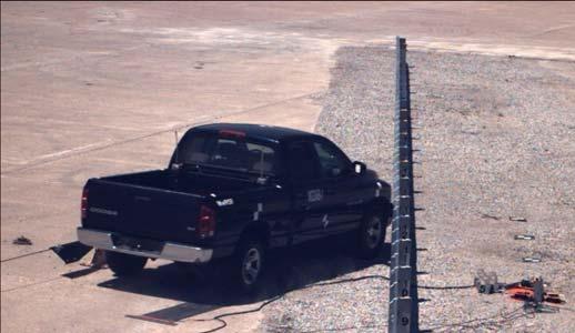
3 Reid, Faller, Bielenberg, and Lechtenberg 3 DESIGN DETAILS The standard MGS formed the basis for the barrier system. However, the MGS was modified by removing the 12-in. (305-mm) deep wood spacer blocks and incorporating W-beam backup plates. The test installation consisted of 181 ft-3 in. (55.25 m) of standard 12-gauge (2.66-mm thick) W-beam supported by steel posts. Complete design details as well as the results of the testing are provided in MwRSF report TRP [15]. System layouts of the tested systems are shown in Figure 1. MGSNB-1 MGSNB-2 FIGURE 1 System Layout
4 Reid, Faller, Bielenberg, and Lechtenberg 4 The system was constructed with twenty-nine guardrail posts spaced 75 in. (1,905 mm) on center. Post nos. 3 through 27 were galvanized ASTM A992 steel W6x8.5 (W152x12.6) sections measuring 6 ft (1.8 m) long with a soil embedment depth of 40 in. (1,016 mm). Post nos. 1, 2, 28, and 29 were breakaway cable terminal (BCT) timber posts measuring 5½ in. wide x 7½ in. deep x 46 in. long (140 mm x 191 mm x 1,168 mm) and were placed in 6-ft (1.8-m) long foundation tubes. All posts were placed in a compacted coarse, crushed limestone material as recommended in MASH. Rail splices were placed at the midspan locations between guardrail posts. All lap splice connections between the rail sections were configured with the upstream segment in front to reduce vehicle snag at the splice during the crash test. For post nos. 3 through 27, 12-in. (305- mm) long, 12-gauge (2.66-mm thick) W-beam backup plates were located between the rail and the front face of the steel posts. Anchorage systems similar to those used on tangent guardrail terminals were utilized on both the upstream and downstream ends of the guardrail system. The mounting height of the W-beam was test dependent. For the pickup test, MGSNB-1, the top mounting height was 31 in. (787 m) above ground with a 24⅞ in. (632-mm) center mounting height. While for the small car test, MGSNB-2, the rail was raised 1 in. (25 mm) such that the height to the top of the guardrail was 32 in. (813 mm). The rail was attached to the posts using ASTM A307 5/8 x 1½ [M16x38] long guardrail bolts and nuts. TEST REQUIREMENTS AND EVALUATION CRITERIA Longitudinal barriers, such as W-beam guardrails, have been required to satisfy the impact safety standards provided in MASH to be eligible according to the FHWA for use on National Highway System (NHS) construction projects or as a replacement for existing designs not meeting current safety standards. According to TL-3 criteria found in MASH, longitudinal barriers must be subjected to two full-scale vehicle crash tests: (1) a 2,425-lb (1,100-kg) passenger car impacting at a speed of 62 mph (100 km/h) and at an angle of 25 degrees and (2) a 5,000-lb (2,268-kg) pickup truck impacting at a speed of 62 mph (100 km/h) and at an angle of 25 degrees. The evaluation criteria for full-scale vehicle crash testing are based on three appraisal areas: (1) structural adequacy; (2) occupant risk; and (3) vehicle trajectory after collision. Criteria for structural adequacy are intended to evaluate the ability of the guardrail to contain and redirect the vehicle. In addition, controlled lateral deflection of the test article is acceptable. Occupant risk evaluates the degree of hazard to occupants in the impacting vehicle. Vehicle trajectory after collision is a measure of the potential for the post-impact trajectory of the vehicle to result in multi-vehicle accidents. This criterion also indicates the potential for safety hazard for the occupants of other vehicles or occupants of the crash vehicle when subjected to secondary collisions with other fixed objects. These three evaluation criteria are described in greater detail in MASH.
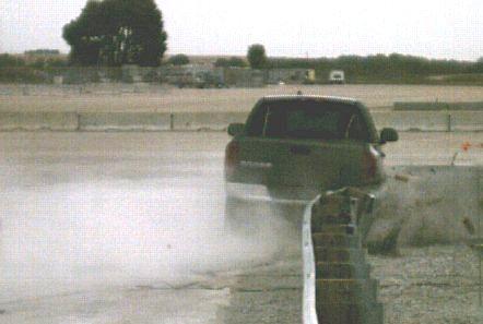
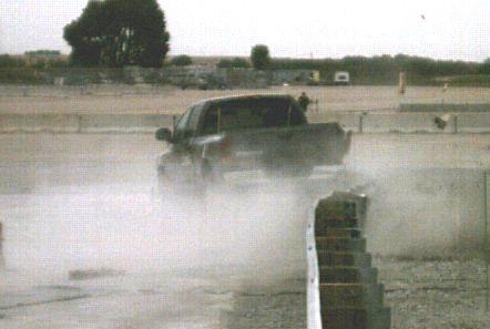
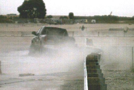
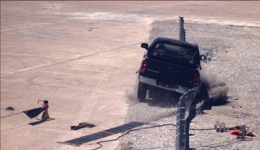
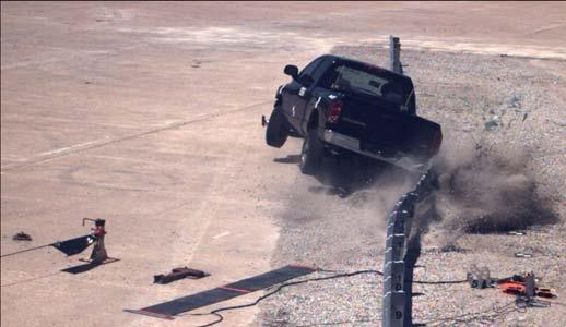
5 Reid, Faller, Bielenberg, and Lechtenberg 5 FULL-SCALE CRASH TESTING Test No. MGSNB-1 Pickup Truck Test For test no. MGSNB-1, a 5,181-lb (2,350-kg) pickup truck impacted the non-blocked MGS at a speed of 62.7 mph (100.9 km/h) and at an angle of 24.7 degrees. A summary of the test results are shown in Figure 2. Initial impact occurred at 9½ in. (0.2 m) upstream from the centerline of post no. 13. At sec after impact, the vehicle became parallel to the guardrail with a speed of 47.9 mph (77.1 km/h). At sec, the vehicle exited the guardrail at an angle of 14.4 degrees and at a speed of 47.4 mph (76.3 km/h). The vehicle was smoothly redirected even though the right-front tire snagged on post no. 15 and was disengaged from the vehicle. Exterior vehicle damage was moderate, and the interior occupant compartment deformations were minimal, with a maximum of 1¼ in. (32 mm), consequently not violating the limits established in MASH. Damage to the barrier was also moderate, consisting mostly of deformed W-beam and guardrail posts as well as contact marks on guardrail and posts. The maximum lateral dynamic rail deflection was 34.1 in. (867 mm) at the mid-span between post nos. 14 and 15. The working width of the system was 43.2 in. (1,097 mm). All occupant risk measures were well below recommended values, and the test vehicle showed no tendency to roll over. Therefore, test no. MGSNB-1 was determined to be acceptable according to the TL-3 safety performance criteria found in MASH. Test No. MGSNB-2 Small Car Test For test no. MGSNB-2, a 2,578-lb (1,169-kg) small car impacted the non-blocked MGS at a speed of 63.0 mph (101.4 km/h) and at an angle of 25.5 degrees. A summary of the test results are shown in Figure 3. Initial impact occurred at 32¼ in. (0.8 m) upstream from the centerline of post no. 14. After impact, the vehicle began to redirect, including a counter-clockwise yaw rotation (i.e., backend towards the rail). At sec after impact, the vehicle snagged on post no. 14 causing the vehicle to essentially stop yawing. At sec, the vehicle exited the guardrail at a trajectory angle of 19.1 degrees and at a speed of 25.7 mph (41.4 km/h). Exterior vehicle damage was moderate, and the interior occupant compartment deformations were minimal, with a maximum deformation of 1¼ in. (32 mm), consequently not violating the limits established in MASH. Damage to the barrier was moderate, consisting mostly of deformed W-beam rail and steel guardrail posts as well as contact marks on guardrail and posts. The maximum lateral dynamic rail deflection was 29.1 in. (740 mm) at the mid-span between post nos. 14 and 15. The working width of the system was 34.5 in. (877 mm). All occupant risk measures were well below recommended values, and the test vehicle showed no tendency to roll over. Therefore, test no. MGSNB-2 was determined to be acceptable according to the TL-3 safety performance criteria found in MASH.

6 Reid, Faller, Bielenberg, and Lechtenberg 6 FIGURE 2 Test MGSNB-1 Results

7 Reid, Faller, Bielenberg, and Lechtenberg 7 FIGURE 3 Test MGSNB-2 Results
8 Reid, Faller, Bielenberg, and Lechtenberg 8 COMPARISON BETWEEN BLOCKOUT AND NON-BLOCKOUT MGS TESTING A comparison between the blocked and non-blocked MGS for both the 2270p truck and 1100c small car is presented in Table 1. Rear view sequentials for the 2270p and 1100c tests are shown in Figures 4 and 5, respectively. Barrier damage and vehicle damage are shown in Figures 6 and 7, respectively. Longitudinal and lateral change in velocity plots are shown in Figure 8. TABLE 1 Test Comparisons Comparison of Results MASH Test 3-11 MASH Test 3-10 Standard MGS Non-Blocked MGS Standard MGS Non-Blocked MGS Test Number 2214MG-2 MGSNB MG-3 MGSNB-2 Reference Number [2] [14] [3] [14] Vehicle Impact Conditions Exit Conditions ORD, g's OIV, ft/s (m/s) Designation Speed, mph (km/h) Speed, mph (km/h) Longitudinal Longitudinal 2270p 62.8 (101.1) 39.6 (63.7) (4.7) 2270p 62.7 (100.9) 47.4 (76.3) (5.2) 1100c 60.8 (97.8) 30.1 (48.4) (4.5) 1100c 63.0 (101.4) 25.7 (41.4) (9.5) Test Inertial, lb (kg) Angle, deg Trajectory Angle, deg Lateral Lateral 5,000 (2,268) (4.8) 5,011 (2,273) (5.7) 2,423 (1,099) (5.2) 2,407 (1,092) (4.8) Dynamic 3.6 (1.1) 2.8 (0.9) 3.0 (0.9) 2.4 (0.7) Test Article Deflections, ft (m) Permanent 2.6 (0.8) 1.6 (0.5) 1.7 (0.5) 1.2 (0.4) Working Width 4.1 (1.2) 3.6 (1.1) 4.0 (1.2) 2.9 (0.9) Impact Severity, kip-ft (kn-m) 122 (166) 115 (156) 55 (75) 59 (80) Max. Occupant Compart. Deformation, in. (mm) 0.8 (19) 1.3 (32) 0.2 (6) 1.3 (32) Max. Yaw Angle, deg Max. Roll Angle, deg Max. Pitch Angle, deg Impact Point 18" upstream post 12 10" upstream post 13 46" upstream post 14 32" upstream post 14 Posts detached from rail during impact posts posts posts posts Posts hit by leading tire (wheel snag) posts posts posts posts Posts pulled out of ground none none none posts 14 and 16 Leading tire/wheel disengaged mostly yes tire debeaded yes Each test successfully passed all criteria set forth by MASH. In fact, all data, photos, and videos showed that none of the tests conducted were in any danger of failing any of the criteria. However, there were some noteworthy differences between the blocked and non-blocked results for the respective vehicles.

9 Reid, Faller, Bielenberg, and Lechtenberg 9 FIGURE 4 Rear View of 2270p Truck Tests 2214MG-2 (left) and MGSNB-1 (right)


10 Reid, Faller, Bielenberg, and Lechtenberg 10 FIGURE 5 Rear View of 1100c Car Tests 2214MG-3 (left) and MGSNB-2 (right)

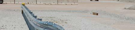
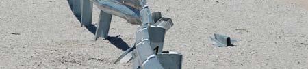


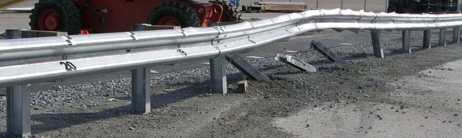
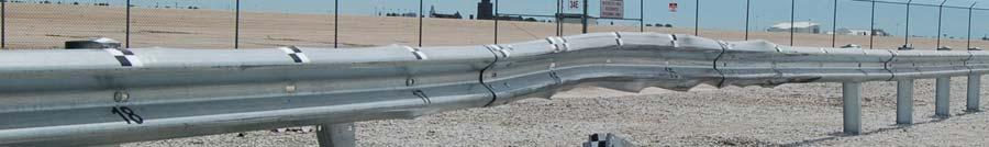
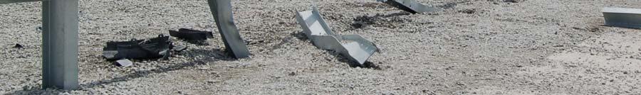
11 Reid, Faller, Bielenberg, and Lechtenberg MG-2 MGSNB MG-3 MGSNB-2 FIGURE 6 Barrier Damage
 2.5 5 7.5 10 12.5 2214MG 2_Blocked MGSNB 1_Non Blocked 15 0 0.05 0.1 0.15 0.2 0.25 0.3 0.35 0.4 0.45 0.")
 0 Longitudinal Change in Velocity 1100c Blocked and Non-Blocked Testing 0 Lateral Change in Velocity 1100c Blocked and Non-Blocked Testing Longitudinal Change in Velocity (m/s) 2.5 5 7.")
12 Reid, Faller, Bielenberg, and Lechtenberg 12 FIGURE 7 Vehicle Damage (left blocked tests, right non-blocked tests) Longitudinal Change in Velocity 2270p Blocked and Non-Blocked Testing Lateral Change in Velocity 2270p Blocked and Non-Blocked Testing 0 0 Longitudinal Change in Velocity (m/s) MG 2_Blocked MGSNB 1_Non Blocked Time (sec) Lateral Change in Velocity (m/s) MG 2_Blocked MGSNB 1_Non Blocked Time (sec) 0 Longitudinal Change in Velocity 1100c Blocked and Non-Blocked Testing 0 Lateral Change in Velocity 1100c Blocked and Non-Blocked Testing Longitudinal Change in Velocity (m/s) MG 3_Blocked 17.5 MGSNB 2_Non Blocked Time (sec) Lateral Change in Velocity (m/s) MG 3_Blocked 17.5 MGSNB 2_Non Blocked Time (sec) FIGURE 8 Longitudinal and Lateral Change In Velocity
13 Reid, Faller, Bielenberg, and Lechtenberg 13 For the 2270p vehicle, the non-blocked test when compared to the blocked test had significantly reduced rail deflections, a roll into the barrier as opposed to away from the barrier, fewer posts detached from the rail, and fewer posts snagged by the tire. The occupant ridedown decelerations (ORD) and occupant impact velocity s (OIV) were, percentage wise, much higher for the non-blocked system; these differences are also somewhat evident by examining the change in velocity plots. However, the occupant risk measures for both systems were small enough to not cause undue concern. In general, the blocked MGS had higher rail deflections and lower occupant risk numbers. For the 1100c vehicle, the non-blocked test compared to the blocked test had significantly reduced rail deflections, a yaw that was essentially stopped due to wheel snag, more posts detached from the rail, and more posts snagged by the tire. The occupant ridedown decelerations were much lower for the non-blocked system. But the longitudinal occupant impact velocity was significantly higher for the non-blocked system due to a large wheel snag early in the nonblocked test. Again, these occupant differences are evident by examining the change in velocity plots. In general, the blocked MGS had higher rail deflections and prevented an early wheel snag that essentially controlled the occupant risk measures for the non-blocked system. Much of the rail deflection differences can probably be attributed to the soil conditions. The more recent non-blocked MGS testing was performed in soil that used a relatively new compaction method, which has been determined to provide a somewhat stiffer soil condition. Thus, most likely, reducing dynamic deflections. Soil conditions for all tests were well within MASH recommendations. Discussion Based on the full-scale testing results, the main advantages of using a blockout for the MGS are threefold: (1) there is improved stability for both vehicles, lower roll and pitch for the pickup truck partially due to an effective rail height increase during post rotation, and smoother redirection for the small car as seen by the consistent/smooth yaw motion; (2) reduced snag on posts which provides for lower longitudinal velocity change for the small car, smoother yaw motion of the small car, and lower longitudinal decelerations for both vehicles, and (3) reduced occupant risk measures, all are better for the truck, while the small car s longitudinal OIV is much better. Additionally for the small car, the non-blocked test did have lower lateral ORD but that was due to lack of yaw caused by wheel snag, and its lower longitudinal ORD was due to high initial longitudinal decelerations, as seen in the early steep drop of longitudinal change in velocity (see Figure 8). Overall, it was concluded that the blocked system performed better than the non-blocked system.
14 Reid, Faller, Bielenberg, and Lechtenberg 14 RAIL-POST ATTACHMENT During MGSNB-1 and MGSNB-2, the locations of the post bolts were varied within the rail slots in order to investigate rail release away from the posts, as indicated in Figure 1 and shown in Figure 9. Post 15 was determined to be the most likely worst case scenario if the rail did not release from the post during impact. As a result, the post bolt was located at the downstream end of the rail slot. For both the pickup and small car tests, the guardrail detached from post 15 as the bolt head was pulled through the rail. Slight tearing of the rail was evident around the rail bolt hole, but not of significance to cause concern for rail rupture. Video analysis also showed that the release of the rail occurred considerably before the post could pull the rail down as the posts rotated in the soil. Further, for both tests, the post bolt at post 16 was initially in the center of the slot. For the truck test, MGSNB-1, post 16 rotated in the soil, the rail did not release from the post, and the tire did not snag on the post. Although in the impact zone, release of the rail for this post was not required for good redirection performance. For the small car test, MGSNB-2, the rail slipped along the bolt, causing the bolt to butt up against the end of the slot. The bolt head was then pulled through the rail in a timely manner, this time without any tearing of the rail around the bolt hole. Similar behavior for rail release under worst case scenarios occurred during testing of the non-blocked MGS for MSE walls. That performance was documented in [14]. In order to prevent the rail from being pulled down as a post rotates in the soil, as well as a possible vehicle override of the barrier during an impact event, the rail may need to detach away from the post. Fortunately, it has been shown that the bolt attachment mechanism used for the MGS, the same one used for standard W-beam guardrail systems for several decades, provides for satisfactory rail detachment.
 FIGURE 9 Bolt Located in Worst Case Location Pull-Through Behavior Still")
15 Reid, Faller, Bielenberg, and Lechtenberg 15 (a) MGSNB-1 (2270p, non-blocked) (b) MGSNB-2 (1100c, non-blocked) FIGURE 9 Bolt Located in Worst Case Location Pull-Through Behavior Still Occurred
16 Reid, Faller, Bielenberg, and Lechtenberg 16 IMPORTANCE OF THE BLOCKOUT The 31-in. mounting height is only one component which contributes to the enhanced performance of the MGS. It is well acknowledged that blockouts serve two primary purposes in the strong-post system. The first, and most important, is causing the rail to rise during an impact. As illustrated in Figure 10, during an impact, the rotation of the posts in conjunction with the blockout causes the rail to rise in the MGS (as well as in Standard W-Beam Guardrail Systems). This is not the case for the 31-in. W-Beam Guardrail System without blockouts; where the rail immediately begins to drop as the post rotates in the soil. The deeper blockout on the MGS has significantly improved performance in concert with the increased mounting height. FIGURE 10 Post/Rail Rotation During Impact - Blockout Holds Rail Up As indicated by the successful crash testing, this does not mean that the non-blocked MGS system is unsafe. Even though the rail is dropping upon post rotation in the non-blocked system, it is not dropping below a critical height during the initial 25 degrees of rotation. In fact, the rail of the 31-in. height MGS with no blockout after 25 degrees of rotation is approximately at the initial height of standard metric W-beam guardrail system. Post-in-soil rotation of 25 degrees is considered a reasonable amount for absorbing a significant amount of energy of the impacting vehicle. However, the larger blockout depth clearly increases the effective guardrail height. The second function of the blockout is to keep vehicles away from the posts, thus reducing both the potential for wheel snag and the amount of wheel snag if it were to occur. Although in all of the testing of the MGS and its variations over the past decade, wheel snag has never proven to be a problem. However, it is prudent to avoid unnecessary impacts of major components. While our surrogate test vehicles may function without blockouts, many other vehicles on the road may suffer degraded performance when interacting with a no-blockout system.

. It also helped pull post 14 out-of-the-ground as well as helped disengage the tire/wheel during the test.")
17 Reid, Faller, Bielenberg, and Lechtenberg 17 A significant wheel snag occurred at post 14 during test MGSNB-2 which did not occur during test 2214MG-3, as shown in Figure 11. Initial impact for both tests was just upstream of post 13, and each vehicle easily cleared post 13 without tire-post overlap. The wheel snag at post 14 during MGSNB-1 was the cause for the relatively abrupt change in longitudinal velocity (see Figure 8), as well as the relatively high OIV compared to the blocked test, 2214MG-3 (31.3 ft/s versus 14.8 ft/s). It also helped pull post 14 out-of-the-ground as well as helped disengage the tire/wheel during the test. 2214MG-3 Blocked MGSNB-2 Non-Blocked FIGURE c Crash Tests at Post 14 Blockout Reduces Wheel Snag CONCLUSIONS AND RECOMMENDATIONS The non-proprietary, non-blocked MGS was successfully crash tested using both the 1100c small car and 2270p pickup truck vehicles according to TL-3 safety performance guidelines provided in MASH. Based on this research, the non-blocked MGS has demonstrated to be a safe and viable option for use in areas where the roadway space is limited. The non-blocked MGS provides an economical design variation of the MGS for such applications. Previously, it has been demonstrated that wood blockouts used in combination with the MGS greatly increases barrier capacity, often reduces occupant risk, and improves the vehicle post-impact trajectory compared to standard W-beam guardrail systems. Now, based on comparing the blocked to the non-blocked MGS test results, it is concluded that the blocked MGS performs better than the non-blocked MGS. Thus, it is recommended that 12-in. (305-mm) deep wood spacer blocks, or acceptable alternatives, be used with the MGS whenever the roadside geometry can accommodate a guardrail system with increased width. Several variations of the MGS system have been developed for special applications, which may be more sensitive to the elimination of the blockouts. These special applications would include the MGS long span system, MGS adjacent to 2:1 fill slopes, MGS on 8:1 approach slopes, MGS adjacent to curb, MGS stiffness transition to approach guardrail transitions, MGS
18 Reid, Faller, Bielenberg, and Lechtenberg 18 with reduced post spacing, and MGS with various wood posts. Since several MGS variations are available, recommendations regarding the use of a blockout will likely vary depending on the nature and behavior of the special applications listed above. Implementation guidance and/or recommendations regarding the use or omission of blockouts in these special applications are discussed in detail in the report documenting this project [15]. DISCLAIMER The contents of this report reflect the views of the authors who are responsible for the facts and the accuracy of the data presented herein. The contents do not necessarily reflect the official views or policies of the Federal Highway Administration. This report does not constitute a standard, specification, or regulation. ACKNOWLEDGEMENTS The authors acknowledge two major sources that made contributions to this project: the Midwest States Regional Pooled Fund Program for sponsoring the research project, and the Midwest Roadside Safety Facility personnel for constructing the barriers, conducting the crash tests, documenting the results and writing portions of the related research report. REFERENCES 1. Faller, R.K., Polivka, K.A., Kuipers, B.D., Bielenberg, B.W., Reid, J.D., Rohde, J.R., and Sicking, D.L., Midwest Guardrail System for Standard and Special Applications, Transportation Research Record No. 1890, Transportation Research Board of the National Academies, Washington, D.C., 2004, pp Polivka, K.A., Faller, R.K., Sicking, D.L., Rohde, J.R., Bielenberg, B.W., and Reid, J.D., Performance Evaluation of the Midwest Guardrail System - Update to NCHRP 350 Test No with 28 C.G. Height (2214MG-2). Final Report to the National Cooperative Highway Research Program, MwRSF Research Report No. TRP , Midwest Roadside Safety Facility, University of Nebraska-Lincoln, October 11, Polivka, K.A., Faller, R.K., Sicking, D.L., Rohde, J.R., Bielenberg, B.W., and Reid, J.D., Performance Evaluation of the Midwest Guardrail System - Update to NCHRP 350 Test No (2214MG-3). Final Report to the National Cooperative Highway Research Program, MwRSF Research Report No. TRP , Midwest Roadside Safety Facility, University of Nebraska-Lincoln, October 11, Gutierrez, D.A., Lechtenberg, K.A., Faller, R.K., Reid, J.D., and Sicking, D.L., Midwest Guardrail System (MGS) with Southern Yellow Pine Posts, MwRSF Research Report No. TRP , Midwest Roadside Safety Facility, University of Nebraska-Lincoln, Lincoln, NE, Ross, H.E., Sicking, D.L., Zimmer, R.A., and Michie, J.D., Recommended Procedures for the Safety Performance Evaluation of Highway Features, National Cooperative Highway
19 Reid, Faller, Bielenberg, and Lechtenberg 19 Research Program (NCHRP) Report No. 350, Transportation Research Board, Washington, D.C., Manual for Assessing Safety Hardware (MASH), American Association of State Highway and Transportation Official (AASHTO), Washington, D.C., Baxter, J.R., Federal Highway Administration (FHWA), Acceptance Letter NCHRP Report 350 TL-3 Testing of the T-31 W-beam Guardrail, HSA-10/B-140, November 3, Baxter, J.R., Federal Highway Administration (FHWA), Acceptance Letter Gregory Mini Spacer (GMS), HSA-10/B-150, October 27, Rice, G.E., Federal Highway Administration (FHWA), Acceptance Letter Nucor Strong Post W-Beam Guardrail System with no blockouts, HSSD/B-162, September 11, Faller, R.K., Sicking, D.L., Bielenberg, R.W., Rohde, J.R., Polivka, K.A., and Reid, J.D., Performance of Steel-Post W-Beam Guardrail Systems, Transportation Research Record No. 2025, Transportation Research Board of the National Academies, Washington, D.C., 2007, pp Reid, J.D., Kuipers, B.D., Sicking, D.L., and Faller, R.K., Impact Performance of W-Beam Guardrail Installed at Various Flare Rates, International Journal of Impact Engineering, Volume 36, Issue 3, March 2009, pages Bielenberg, R.W., Faller, R.K., Sicking, D.L., Rohde, J.R., and Reid, J.D., Midwest Guardrail System for Long Span Culvert Applications, Paper No , Transportation Research Record No. 2025, Transportation Research Board of the National Academies, Washington, D.C., 2007, pp Polivka, K.A., Faller, R.K., Sicking, D.L., and Bielenberg, R.W., Midwest Guardrail System Adjacent to a 2:1 Slope, Transportation Research Record No. 2060, Transportation Research Board of the National Academies, Washington, D.C., 2008, pp Lechtenberg, K.A., Faller, R.K., Rohde, J.R., Sicking, D.L., and Reid, J.D., Non-Blocked Midwest Guardrail System for Wire-Faced Walls of Mechanically Stabilized Earth, Transportation Research Record 2262, Transportation Research Board of the National Academies, Washington, D.C., 2011, pp Schrum, K.D., Lechtenberg, K.A., Rosenbaugh, S.K., Faller, R.K., Reid, J.D., and Sicking, D.L., Safety Performance Evaluation of the Non-Blocked Midwest Guardrail System (MGS), MwRSF Research Report No. TRP , Midwest Roadside Safety Facility, University of Nebraska-Lincoln, Lincoln, NE, October 23, 2012.
MINIMUM EFFECTIVE LENGTH FOR THE MIDWEST GUARDRAIL SYSTEM
 Duplication for publication or sale is strictly prohibited without prior written permission of the Transportation Research Board Paper No. 15-0484 MINIMUM EFFECTIVE LENGTH FOR THE MIDWEST GUARDRAIL SYSTEM
Development and Implementation of the Simplified MGS Stiffness Transition
 Duplication for publication or sale is strictly prohibited without prior written permission of the Transportation Research Board Paper No. 12-3367 Development and Implementation of the Simplified MGS Stiffness
DEVELOPMENT OF A MASH TL-3 TRANSITION BETWEEN GUARDRAIL AND PORTABLE CONCRETE BARRIERS
 Duplication for publication or sale is strictly prohibited without prior written permission of the Transportation Research Board Paper No. 17-01712 DEVELOPMENT OF A MASH TL-3 TRANSITION BETWEEN GUARDRAIL
Evaluation of the Midwest Guardrail System Stiffness Transition with Curb
 Duplication for publication or sale is strictly prohibited without prior written permission of the Transportation Research Board Paper No. -0 Evaluation of the Midwest Guardrail System Stiffness Transition
Evaluation of the Midwest Guardrail System stiffness transition with curb
 University of Nebraska - Lincoln DigitalCommons@University of Nebraska - Lincoln Civil Engineering Faculty Publications Civil Engineering 2016 Evaluation of the Midwest Guardrail System stiffness transition
SGR52 TOP-MOUNTED WEAK-POST GUARDRAIL ATTACHED TO CULVERT PLAN VIEW ELEVATION VIEW DETAIL B DETAIL A SHEET NO. DATE: 37 1/2" 953 (TYP) 150" 3810
 150 3810") PLAN VIEW C 150" 3810 37 1/2" 953 (TYP) A B C 8-FBB01 RWB01a FWR01 RWM04a FWR01 RWB01a RWM04a PSF01 FBX08a PSF01 FBX08a DETAIL A DETAIL B 1 of 7 12/5/2016 INTENDED USE The Top-Mounted Weak-Post Guardrail
PLAN VIEW C 150" 3810 37 1/2" 953 (TYP) A B C 8-FBB01 RWB01a FWR01 RWM04a FWR01 RWB01a RWM04a PSF01 FBX08a PSF01 FBX08a DETAIL A DETAIL B 1 of 7 12/5/2016 INTENDED USE The Top-Mounted Weak-Post Guardrail
CRITICAL FLARE RATES FOR W-BEAM GUARDRAIL DETERMINING MAXIMUM CAPACITY USING COMPUTER SIMULATION NCHRP 17-20(3)
") CRITICAL FLARE RATES FOR W-BEAM GUARDRAIL DETERMINING MAXIMUM CAPACITY USING COMPUTER SIMULATION NCHRP 17-2(3) Submitted by Beau D. Kuipers, B.S.M.E., E.I.T. Graduate Research Assistant Ronald K. Faller,
CRITICAL FLARE RATES FOR W-BEAM GUARDRAIL DETERMINING MAXIMUM CAPACITY USING COMPUTER SIMULATION NCHRP 17-2(3) Submitted by Beau D. Kuipers, B.S.M.E., E.I.T. Graduate Research Assistant Ronald K. Faller,
A MASH Compliant W-Beam Median Guardrail System
 0 0 0 0 0 A MASH Compliant W-Beam Median Guardrail System By A. Y. Abu-Odeh, R. P. Bligh, W. Odell, A. Meza, and W. L. Menges Submitted: July 0, 0 Word Count:, + ( figures + tables=,000) =, words Authors:
PERFORMANCE EVALUATION OF THE MODIFIED G4(1S) GUARDRAIL UPDATE TO NCHRP 350 TEST NO WITH 28" C.G. HEIGHT (2214WB-2)
 GUARDRAIL UPDATE TO NCHRP 350 TEST NO WITH 28 C.G. HEIGHT (2214WB-2)") PERFORMANCE EVALUATION OF THE MODIFIED G4(1S) GUARDRAIL UPDATE TO NCHRP 350 TEST NO. 3-11 WITH 28" C.G. HEIGHT (2214WB-2) Submitted by Karla A. Polivka, M.S.M.E., E.I.T. Research Associate Engineer Dean
PERFORMANCE EVALUATION OF THE MODIFIED G4(1S) GUARDRAIL UPDATE TO NCHRP 350 TEST NO. 3-11 WITH 28" C.G. HEIGHT (2214WB-2) Submitted by Karla A. Polivka, M.S.M.E., E.I.T. Research Associate Engineer Dean
Advances in Simulating Corrugated Beam Barriers under Vehicular Impact
 13 th International LS-DYNA Users Conference Session: Automotive Advances in Simulating Corrugated Beam Barriers under Vehicular Impact Akram Abu-Odeh Texas A&M Transportation Institute Abstract W-beam
DEFLECTION LIMITS FOR TEMPORARY CONCRETE BARRIERS
 Midwest State s Regional Pooled Fund Research Program Fiscal Year 1998-1999 (Year 9) NDOR Research Project Number SPR-3(017) DEFLECTION LIMITS FOR TEMPORARY CONCRETE BARRIERS Submitted by Dean L. Sicking,
VERIFICATION & VALIDATION REPORT of MGS Barrier Impact with 1100C Vehicle Using Toyota Yaris Coarse FE Model
 VERIFICATION & VALIDATION REPORT of MGS Barrier Impact with 1100C Vehicle Using Toyota Yaris Coarse FE Model CCSA VALIDATION/VERIFICATION REPORT Page 1 of 4 Project: CCSA Longitudinal Barriers on Curved,
SUMMARY CHANGES FOR NCHRP REPORT 350 GUIDELINES [NCHRP (02)] Keith A. Cota, Chairman Technical Committee on Roadside Safety June 14, 2007
![SUMMARY CHANGES FOR NCHRP REPORT 350 GUIDELINES [NCHRP (02)] Keith A. Cota, Chairman Technical Committee on Roadside Safety June 14, 2007](/thumbs/87/97351925.jpg "SUMMARY CHANGES FOR NCHRP REPORT 350 GUIDELINES [NCHRP (02)] Keith A. Cota, Chairman Technical Committee on Roadside Safety June 14, 2007") SUMMARY CHANGES FOR NCHRP REPORT 350 GUIDELINES [NCHRP 22-14 (02)] Keith A. Cota, Chairman Technical Committee on Roadside Safety June 14, 2007 BACKGROUND Circular 482 (1962) First full scale crash test
SUMMARY CHANGES FOR NCHRP REPORT 350 GUIDELINES [NCHRP 22-14 (02)] Keith A. Cota, Chairman Technical Committee on Roadside Safety June 14, 2007 BACKGROUND Circular 482 (1962) First full scale crash test
AASHTO Manual for Assessing Safety Hardware, AASHTO/FHWA Joint Implementation Plan Standing Committee on Highways September 24, 2015
 AASHTO Manual for Assessing Safety Hardware, 2015 AASHTO/FHWA Joint Implementation Plan Standing Committee on Highways September 24, 2015 Full Scale MASH Crash Tests (NCHRP 22-14(02)) Conducted several
EXTENDING TL-2 SHORT-RADIUS GUARDRAIL TO LARGER RADII
 Research Project Number TPF-5(193) Supplement 27 EXTENDING TL-2 SHORT-RADIUS GUARDRAIL TO LARGER RADII Submitted by Cody S. Stolle, Ph.D., E.I.T. Post-Doctoral Research Associate Robert W. Bielenberg,
INCREASED SPAN LENGTH FOR THE MGS LONG-SPAN GUARDRAIL SYSTEM PART III: FAILURE ANALYSIS
 Midwest States Pooled Fund Research Program Fiscal Years 2013 (Years 23) Research Project Number TPF-5(193) Supplement #56 NDOR Sponsoring Agency Code RPFP-13-MGS-3 INCREASED SPAN LENGTH FOR THE MGS LONG-SPAN
Evaluation and Design of ODOT s Type 5 Guardrail with Tubular Backup
 Evaluation and Design of ODOT s Type 5 Guardrail with Tubular Backup Draft Final Report Chuck A. Plaxico, Ph.D. James C. Kennedy, Jr., Ph.D. Charles R. Miele, P.E. for the Ohio Department of Transportation
Analysis of Existing Work-Zone Sign Supports Using Manual for Assessing Safety Hardware Safety Performance Criteria
 University of Nebraska - Lincoln DigitalCommons@University of Nebraska - Lincoln Civil Engineering Faculty Publications Civil Engineering 2011 Analysis of Existing Work-Zone Sign Supports Using Manual
Assessing Options for Improving Roadside Barrier Crashworthiness
 13 th International LS-DYNA Users Conference Session: Simulation Assessing Options for Improving Roadside Barrier Crashworthiness D. Marzougui, C.D. Kan, and K.S. Opiela Center for Collision Safety and
Crash Testing Growth Common Roadside Hardware Systems Draft FHWA and AASHTO Requirements for Implementing MASH 2015
 64 th Annual Illinois Traffic Safety and Engineering Conference October 14, 2015 Crash Testing Growth Common Roadside Hardware Systems Draft FHWA and AASHTO Requirements for Implementing MASH 2015 1 https://www.youtube.com/watch?feature
PR V2. Submitted by. Professor MIDWEST Vine Street (402) Submitted to
 Submitted to") FINAL REPORT PR4893118-V2 ZONE OF INTRUSION STUDY Submitted by John D. Reid, Ph.D. Professor Dean L.. Sicking, Ph.D., P.E. Professorr and MwRSF Director MIDWEST ROADSIDE SAFETY FACILITY University of Nebraska-Lincoln
FINAL REPORT PR4893118-V2 ZONE OF INTRUSION STUDY Submitted by John D. Reid, Ph.D. Professor Dean L.. Sicking, Ph.D., P.E. Professorr and MwRSF Director MIDWEST ROADSIDE SAFETY FACILITY University of Nebraska-Lincoln
DEVELOPMENT OF A TRANSITION BETWEEN FREE-STANDING AND REDUCED-DEFLECTION PORTABLE CONCRETE BARRIERS PHASE I
 Research Project Number TPF-5(193) Supplement #78 DEVELOPMENT OF A TRANSITION BETWEEN FREE-STANDING AND REDUCED-DEFLECTION PORTABLE CONCRETE BARRIERS PHASE I Submitted by Mojdeh Asadollahi Pajouh, Ph.D.
VULCAN BARRIER TL-3 GENERAL SPECIFICATIONS
 VULCAN BARRIER TL-3 GENERAL SPECIFICATIONS I. GENERAL A. The VULCAN BARRIER TL-3 (VULCAN TL-3) shall be a highly portable and crashworthy longitudinal barrier especially suited for use as a temporary barrier
Product Specification. ABSORB 350 TM TL-2 Non-Redirective, Gating, Crash Cushion Applied to Quickchange Moveable Barrier
 TB 000612 Rev. 0 Page 1 of 9 Product Specification ABSORB 350 TM TL-2 Non-Redirective, Gating, Crash Cushion Applied to Quickchange Moveable Barrier I. General The ABSORB 350 TM TL-2 System is a Non-Redirective,
Manual for Assessing Safety Hardware
 American Association of State Highway and Transportation Officials Manual for Assessing Safety Hardware 2009 vii PREFACE Effective traffic barrier systems, end treatments, crash cushions, breakaway devices,
1962: HRCS Circular 482 one-page document, specified vehicle mass, impact speed, and approach angle for crash tests.
 1 2 3 1962: HRCS Circular 482 one-page document, specified vehicle mass, impact speed, and approach angle for crash tests. 1973: NCHRP Report 153 16-page document, based on technical input from 70+ individuals
VULCAN BARRIER TL-3 GENERAL SPECIFICATIONS
 VULCAN BARRIER TL-3 GENERAL SPECIFICATIONS I. GENERAL A. The VULCAN BARRIER TL-3 (VULCAN TL-3) shall be a highly portable and crashworthy longitudinal barrier especially suited for use as a temporary barrier
SAFETY PERFORMANCE OF WORK-ZONE DEVICES UNDER MASH TESTING
 SAFETY PERFORMANCE OF WORK-ZONE DEVICES UNDER MASH TESTING Schmidt, Faller, Lechtenberg, Sicking, Holloway Midwest Roadside Safety Facility Nebraska Transportation Center University of Nebraska-Lincoln
MASH TEST 3-10 ON 31-INCH W-BEAM GUARDRAIL WITH STANDARD OFFSET BLOCKS
 TTI: 9-1002 MASH TEST 3-10 ON 31-INCH W-BEAM GUARDRAIL WITH STANDARD OFFSET BLOCKS ISO 17025 Laboratory Testing Certificate # 2821.01 Crash testing performed at: TTI Proving Ground 3100 SH 47, Building
PERFORMANCE EVALUATION OF THE PERMANENT NEW JERSEY SAFETY SHAPE BARRIER UPDATE TO NCHRP 350 TEST NO (2214NJ-2)
") PERFORMANCE EVALUATION OF THE PERMANENT NEW JERSEY SAFETY SHAPE BARRIER UPDATE TO NCHRP 350 TEST NO. 4-12 (2214NJ-2) Submitted by Karla A. Polivka, M.S.M.E., E.I.T. Research Associate Engineer Dean L.
PERFORMANCE EVALUATION OF THE PERMANENT NEW JERSEY SAFETY SHAPE BARRIER UPDATE TO NCHRP 350 TEST NO. 4-12 (2214NJ-2) Submitted by Karla A. Polivka, M.S.M.E., E.I.T. Research Associate Engineer Dean L.
PERFORMANCE EVALUATION OF THE FREE-STANDING TEMPORARY BARRIER UPDATE TO NCHRP 350 TEST NO WITH 28" C.G. HEIGHT (2214TB-2)
") PERFORMANCE EVALUATION OF THE FREE-STANDING TEMPORARY BARRIER UPDATE TO NCHRP 350 TEST NO. 3-11 WITH 28" C.G. HEIGHT (2214TB-2) Submitted by Karla A. Polivka, M.S.M.E., E.I.T. Research Associate Engineer
PERFORMANCE EVALUATION OF THE FREE-STANDING TEMPORARY BARRIER UPDATE TO NCHRP 350 TEST NO. 3-11 WITH 28" C.G. HEIGHT (2214TB-2) Submitted by Karla A. Polivka, M.S.M.E., E.I.T. Research Associate Engineer
July 10, Refer to: HSA-10/CC-78A
 July 10, 2003 Refer to: HSA-10/CC-78A Barry D. Stephens, P.E. Senior Vice President of Engineering ENERGY ABSORPTION Systems, Inc. 3617 Cincinnati Avenue Rocklin, California 95765 Dear Mr. Stephens: Your
PERFORMANCE EVALUATION OF THE FREE-STANDING TEMPORARY BARRIER UPDATE TO NCHRP 350 TEST NO (2214TB-1)
") PERFORMANCE EVALUATION OF THE FREE-STANDING TEMPORARY BARRIER UPDATE TO NCHRP 350 TEST NO. 3-11 (2214TB-1) Submitted by Karla A. Polivka, M.S.M.E., E.I.T. Research Associate Engineer Dean L. Sicking, Ph.D.,
PERFORMANCE EVALUATION OF THE FREE-STANDING TEMPORARY BARRIER UPDATE TO NCHRP 350 TEST NO. 3-11 (2214TB-1) Submitted by Karla A. Polivka, M.S.M.E., E.I.T. Research Associate Engineer Dean L. Sicking, Ph.D.,
Continued Development of a Non-Proprietary, High-Tension, Cable End Terminal System
 University of Nebraska - Lincoln DigitalCommons@University of Nebraska - Lincoln Nebraska Department of Transportation Research Reports Nebraska LTAP 4-29-2016 Continued Development of a Non-Proprietary,
Research Project Number SPR-P1(13)M326 DEVELOPMENT OF A MASH TL-3 TRANSITION BETWEEN GUARDRAIL AND PORTABLE CONCRETE BARRIERS.
M326 DEVELOPMENT OF A MASH TL-3 TRANSITION BETWEEN GUARDRAIL AND PORTABLE CONCRETE BARRIERS.") Research Project Number SPR-P1(13)M326 DEVELOPMENT OF A MASH TL-3 TRANSITION BETWEEN GUARDRAIL AND PORTABLE CONCRETE BARRIERS Submitted by David A. Gutierrez, B.S.C.E., E.I.T. Graduate Research Assistant
Research Project Number SPR-P1(13)M326 DEVELOPMENT OF A MASH TL-3 TRANSITION BETWEEN GUARDRAIL AND PORTABLE CONCRETE BARRIERS Submitted by David A. Gutierrez, B.S.C.E., E.I.T. Graduate Research Assistant
Universal TAU-IIR Redirective, Non-Gating, Crash Cushion
 TB 110927 Rev. 0 Page 1 of 5 Product Specification Universal TAU-IIR Redirective, Non-Gating, Crash Cushion I. General The Universal TAU-IIR system is a Redirective, Non-Gating Crash Cushion in accordance
W-Beam Guiderail Transition from Light to Heavy Posts
 TRANSPORTATION RESEARCH RECORD 1198 55 W-Beam Guiderail Transition from Light to Heavy Posts DONALD G. HERRING AND JAMES E. BRYDEN Two full-scale crash tests evaluated a transition between lightand heavy-post
COMPARISON OF THE IMPACT PERFORMANCE OF THE G4(1W) AND G4(2W) GUARDRAIL SYSTEMS UNDER NCHRP REPORT 350 TEST 3-11 CONDITIONS
 AND G4(2W) GUARDRAIL SYSTEMS UNDER NCHRP REPORT 350 TEST 3-11 CONDITIONS") Paper No. 00-0525 COMPARISON OF THE IMPACT PERFORMANCE OF THE G4(1W) AND G4(2W) GUARDRAIL SYSTEMS UNDER NCHRP REPORT 350 TEST 3-11 CONDITIONS by Chuck A. Plaxico Associate Research Engineer Worcester Polytechnic
Paper No. 00-0525 COMPARISON OF THE IMPACT PERFORMANCE OF THE G4(1W) AND G4(2W) GUARDRAIL SYSTEMS UNDER NCHRP REPORT 350 TEST 3-11 CONDITIONS by Chuck A. Plaxico Associate Research Engineer Worcester Polytechnic
February 8, In Reply Refer To: HSSD/CC-104
 February 8, 2008 200 New Jersey Avenue, SE. Washington, DC 20590 In Reply Refer To: HSSD/CC-04 Barry D. Stephens, P.E. Sr. Vice President Engineering Energy Absorption Systems, Inc. 367 Cincinnati Avenue
MASH 2016 Implementation: What, When and Why
 MASH 2016 Implementation: What, When and Why Roger P. Bligh, Ph.D., P.E. Senior Research Engineer Texas A&M Transportation Institute June 7, 2016 2016 Traffic Safety Conference College Station, Texas Outline
INCREASED SPAN LENGTH FOR THE MGS LONG-SPAN GUARDRAIL SYSTEM
 University of Nebraska - Lincoln DigitalCommons@University of Nebraska - Lincoln Mechanical (and Materials) Engineering -- Dissertations, Theses, and Student Research Mechanical & Materials Engineering,
Crash Performance of Strong-Post W-Beam Guardrail with Missing Blockouts Carolyn E. Hampton and Hampton C. Gabler
 Crash Performance of Strong-Post W-Beam Guardrail with Missing Blockouts Carolyn E. Hampton and Hampton C. Gabler Virginia Tech Center for Injury Biomechanics, Blacksburg VA 24061 Abstract Missing blockouts
June 5, In Reply Refer To: HSSD/B-178. Mr. Kevin K. Groeneweg Mobile Barriers LLC Genesee Trail Road Golden, CO Dear Mr.
 June 5, 2008 1200 New Jersey Avenue, SE. Washington, DC 20590 In Reply Refer To: HSSD/B-178 Mr. Kevin K. Groeneweg Mobile Barriers LLC 24918 Genesee Trail Road Golden, CO 80401 Dear Mr. Groeneweg: This
Sponsored by Roadside Safety Research Program Pooled Fund Study
 Proving Ground Report No. 405160-10 Report Date: August 2010 EVALUATION OF EXISTING T-INTERSECTION GUARDRAIL SYSTEMS FOR EQUIVALENCY WITH NCHRP REPORT 350 TL-2 TEST CONDITIONS by Akram Y. Abu-Odeh Associate
TEST MATRICES FOR EVALUATING CABLE MEDIAN BARRIERS PLACED IN V-DITCHES
 Midwest States Regional Pooled Fund Research Program Fiscal Year 2012 (Year 22) Research Project Number TPF-5(193) Supplement #44 NDOR Sponsoring Agency Code RPFP-12-CABLE1&2 TEST MATRICES FOR EVALUATING
Slotted Rail Guardrail Terminal
 TRANSPORTATION RESEARCH RECORD 1500 43 Slotted Rail Guardrail Terminal KING K. MAK, ROGER P. BLIGH, HAYES E. Ross, JR., AND DEAN L. SICKING A slotted rail terminal (SRT) for W-beam guardrails was successfully
W-Beam Approach Treatment at Bridge Rail Ends Near Intersecting Roadways
 TRANSPORTATION RESEARCH RECORD 1133 51 W-Beam Approach Treatment at Bridge Rail Ends Near Intersecting Roadways M. E. BRONSTAD, M. H. RAY, J. B. MAYER, JR., AND c. F. MCDEVITT This paper is concerned with
Improving Roadside Safety by Computer Simulation
 A2A04:Committee on Roadside Safety Features Chairman: John F. Carney, III, Worcester Polytechnic Institute Improving Roadside Safety by Computer Simulation DEAN L. SICKING, University of Nebraska, Lincoln
Development of a Slotted-Rail Breakaway Cable Terminal
 TRANSPORTATION RESEA RCH RECORD 1233 65 Development of a Slotted-Rail Breakaway Cable Terminal DEAN L. SICKING, ASIF B. QuRESHY, AND HAYES E. Ross, JR. Development of the Slotted-Rail Breakaway Cable Terminal
June 27, In Reply Refer To: HSSD/B-176
 June 27, 2008 1200 New Jersey Avenue, SE. Washington, DC 20590 In Reply Refer To: HSSD/B-176 Mr. John Addy Hill & Smith Springvale Business and Industrial Park Bliston, Wolverhampton, West Midlands, UK,
July 17, In Reply Refer To: HSSD/B-176A
 July 17, 2008 1200 New Jersey Avenue, SE. Washington, DC 20590 In Reply Refer To: HSSD/B-176A Mr. John Addy Hill & Smith Springvale Business and Industrial Park Bliston, Wolverhampton, West Midlands, UK,
Development and Validation of a Finite Element Model of an Energy-absorbing Guardrail End Terminal
 Development and Validation of a Finite Element Model of an Energy-absorbing Guardrail End Terminal Yunzhu Meng 1, Costin Untaroiu 1 1 Department of Biomedical Engineering and Virginia Tech, Blacksburg,
Illinois Safety Program IDOT District ATSSA Workshop
 Illinois Safety Program IDOT District ATSSA Workshop Roadway Departure & MASH DRAFT IDOT Facilitator: Dave Piper ATSSA Facilitator: Jim Thonn 1 Illinois Emphasis Area Priority Pyramid 2 Fatalities and
Implementation of AASHTO s Manual for Assessing Safety Hardware (MASH) 2016
 2016") Implementation of AASHTO s Manual for Assessing Safety Hardware (MASH) 2016 Update from the Technical Committee on Roadside Safety Keith Cota, New Hampshire DOT MASH 2016 Overview Background Ballot Results/Dates
Implementation of AASHTO s Manual for Assessing Safety Hardware (MASH) 2016 Update from the Technical Committee on Roadside Safety Keith Cota, New Hampshire DOT MASH 2016 Overview Background Ballot Results/Dates
BarrierGate. General Specifications. Manual Operations General Specifications
 BarrierGate General Specifications Manual Operations General Specifications BarrierGate GENERAL SPECIFICATIONS I. GENERAL A. The BarrierGate system (the gate) shall be designed and manufactured by Energy
NCHRP Report 350 Test 4-12 of the Modified Thrie Beam Guardrail
 NCHRP Report 350 Test 4-12 of the Modified Thrie Beam Guardrail PUBLICATION NO. FHWA-RD-99-065 DECEMBER 1999 Research, Development, and Technology Turner-Fairbank Highway Research Center 6300 Georgetown
DISTRIBUTION: Electronic Recipients List TRANSMITTAL LETTER NO. (15-01) MINNESOTA DEPARTMENT OF TRANSPORTATION. MANUAL: Road Design English Manual
 MINNESOTA DEPARTMENT OF TRANSPORTATION. MANUAL: Road Design English Manual") DISTRIBUTION: Electronic Recipients List MINNESOTA DEPARTMENT OF TRANSPORTATION DEVELOPED BY: Design Standards Unit ISSUED BY: Office of Project Management and Technical Support TRANSMITTAL LETTER NO.
DISTRIBUTION: Electronic Recipients List MINNESOTA DEPARTMENT OF TRANSPORTATION DEVELOPED BY: Design Standards Unit ISSUED BY: Office of Project Management and Technical Support TRANSMITTAL LETTER NO.
TRACC. Trinity Attenuating Crash Cushion
 TRACC Trinity Attenuating Crash Cushion CSP Pacific Business Unit of Fletcher Concrete & Infrastructure Limited 306 Neilson Street Onehunga, Auckland Phone: (09) 634 1239 or 0800 655 200 Fax: (09) 634
s MEDIAN BARRIERS FOR TEXAS HIGHWAYS
 s MEDIAN BARRIERS FOR TEXAS HIGHWAYS SUMMARY REPORT of Research Report Number 146-4 Study 2-8-68-146 Cooperative Research Program of the Texas Transportation Institute and the Texas Highway Department
Cable-to-Post Attachments for Use in Non- Proprietary High-Tension Cable Median Barrier Phase II
 University of Nebraska - Lincoln DigitalCommons@University of Nebraska - Lincoln Nebraska Department of Transportation Research Reports Nebraska LTAP 3-24-2016 Cable-to-Post Attachments for Use in Non-
Correlation of Occupant Evaluation Index on Vehicle-occupant-guardrail Impact System Guo-sheng ZHANG, Hong-li LIU and Zhi-sheng DONG
 07 nd International Conference on Computer, Mechatronics and Electronic Engineering (CMEE 07) ISBN: 978--60595-53- Correlation of Occupant Evaluation Index on Vehicle-occupant-guardrail Impact System Guo-sheng
safedirection.com.au Ref: PM 017/02
 DISTRIBUTOR 0 Product Manual Ref: PM 017/02 Table of Contents 1.0 Introduction... 3 2.0 The... 3 3.0 How the Functions... 4 4.0 Crash Test Performance... 4 5.0 Characteristics of Terminals... 5 5.1 Gating
Evaluation of Barriers for Very High Speed Roadways
 TTI: 0-6071 Evaluation of Barriers for Very High Speed Roadways ISO 17025 Laboratory Testing Certificate # 2821.01 Crash testing performed at: TTI Proving Ground 3100 SH 47, Building 7091 Bryan, TX 77807
Guardrail/Bridgerail Recommendations for Very Low Volume Local Roads in Kansas
 Guardrail/Bridgerail Recommendations for Very Low Volume Local Roads in Kansas MINK Conference September 20, 2017 Ronald J. Seitz, P.E. and Tod Salfrank The Problem The Local Road System in Kansas is Very
METAL BEAM GUARDFENCE TRANSITION AND END TREATMENT IDENTIFICATION GUIDE
 2016 TxDOT Design Division METAL BEAM GUARDFENCE TRANSITION AND END TREATMENT IDENTIFICATION GUIDE A guide to help TxDOT employees identify metal beam guardfence transitions and end treatments for the
ROBUST PROJECT Norwegian Public Roads Administration / Force Technology Norway AS
 ROBUST PROJECT Norwegian Public Roads Administration / Force Technology Norway AS Evaluation of small car - RM_R1 - prepared by Politecnico di Milano Volume 1 of 1 January 2006 Doc. No.: ROBUST-5-002/TR-2004-0039
Form DOT F (8-72) Texas Transportation Institute The Texas A&M University System College Station, Texas
 Texas Transportation Institute The Texas A&M University System College Station, Texas") 1. Report No. FHWA/TX-02/4162-1 Technical Report Documentation Page 2. Government Accession No. 3. Recipient's Catalog No. 4. Title and Subtitle EVALUATION OF TEXAS GRID-SLOT PORTABLE CONCRETE BARRIER
1. Report No. FHWA/TX-02/4162-1 Technical Report Documentation Page 2. Government Accession No. 3. Recipient's Catalog No. 4. Title and Subtitle EVALUATION OF TEXAS GRID-SLOT PORTABLE CONCRETE BARRIER
Sponsored by Roadside Safety Research Program Pooled Fund Study No. TPF-5(114)
") Proving Ground Test Report No. 405160-23-2 Test Report Date: February 2012 MASH TEST 3-11 OF THE W-BEAM GUARDRAIL ON LOW-FILL BOX CULVERT by William F. Williams, P.E. Associate Research Engineer and Wanda
Proving Ground Test Report No. 405160-23-2 Test Report Date: February 2012 MASH TEST 3-11 OF THE W-BEAM GUARDRAIL ON LOW-FILL BOX CULVERT by William F. Williams, P.E. Associate Research Engineer and Wanda
MASH TEST 3-37 OF THE TxDOT 31-INCH W-BEAM DOWNSTREAM ANCHOR TERMINAL
 TTI: 9-1002 MASH TEST 3-37 OF THE TxDOT 31-INCH W-BEAM DOWNSTREAM ANCHOR TERMINAL ISO 17025 Laboratory Testing Certificate # 2821.01 Crash testing performed at: TTI Proving Ground 3100 SH 47, Building
November 16, 1998 Refer to: HNG-14. Mr. David Allardyce Mechanical Engineer B&B Electromatic Main Street Norwood, Louisiana 70761
 November 16, 1998 Refer to: HNG-14 Mr. David Allardyce Mechanical Engineer B&B Electromatic 14113 Main Street Norwood, Louisiana 70761 Dear Mr. Allardyce: In your August 31 letter, you presented some preliminary
MASH Test 3-11 on the T131RC Bridge Rail
 TTI: 9-1002-12 MASH Test 3-11 on the T131RC Bridge Rail ISO 17025 Laboratory Testing Certificate # 2821.01 Crash testing performed at: TTI Proving Ground 3100 SH 47, Building 7091 Bryan, TX 77807 Test
GUARDRAIL TESTING MODIFIED ECCENTRIC LOADER TERMINAL (MELT) AT NCHRP 350 TL-2. Dean C. Alberson, Wanda L. Menges, and Rebecca R.
 AT NCHRP 350 TL-2. Dean C. Alberson, Wanda L. Menges, and Rebecca R.") GUARDRAIL TESTING MODIFIED ECCENTRIC LOADER TERMINAL (MELT) AT NCHRP 350 TL-2 Dean C. Alberson, Wanda L. Menges, and Rebecca R. Haug Prepared for The New England Transportation Consortium July 2002 NETCR
GUARDRAIL TESTING MODIFIED ECCENTRIC LOADER TERMINAL (MELT) AT NCHRP 350 TL-2 Dean C. Alberson, Wanda L. Menges, and Rebecca R. Haug Prepared for The New England Transportation Consortium July 2002 NETCR
Texas Transportation Institute The Texas A&M University System College Station, Texas
 1. Report No. FHWA/TX-07/0-5527-1 4. Title and Subtitle DEVELOPMENT OF A LOW-PROFILE TO F-SHAPE TRANSITION BARRIER SEGMENT 2. Government Accession No. 3. Recipient's Catalog No. Technical Report Documentation
John Rohde, Ph.D., P.E. Associate Professor Department of Civil Engineering University of Nebraska-Lincoln
 Report # MATC-UNL: 222 Final Report 25-1121-1-222 Development of a Socketed Foundation for Cable Barrier Posts - Phase I John Rohde, Ph.D., P.E. Associate Professor Department of Civil Engineering University
Evaluating The Relevancy Of Current Crash Test Guidelines For Roadside Safety Barriers On High Speed Roads
 Evaluating The Relevancy Of Current Crash Test Guidelines For Roadside Safety Barriers On High Speed Roads Connie Xavier Dominique Lord Chiara Dobrovolny Roger Bligh TRB 1 st International Roadside Safety
CRASH TEST OF MILE POST MARKER. T. J. Hirsch Research Engineer. and. Eugene Buth Assistant Research Engineer. Research Report Number 146-8
 CRASH TEST OF MILE POST MARKER by T. J. Hirsch Research Engineer and Eugene Buth Assistant Research Engineer Research Report Number 146-8 Studies of Field Adaption of Impact Attenuation Systems Research
CRASH TEST EVALUATION OF THRIE BEAM TRAFFIC BARRIERS
 CRASH TEST EVALUATION OF THRIE BEAM TRAFFIC BARRIERS M. E. Bronstad and J. D. Michie, Southwest Research Institute; J. G. Viner, Federal Highway Administration; and W. E. Behm, Anderson Safeway Guard Rail
PRODUCT DESCRIPTION. X-Tension DS. is suitable for all road types: Motorways, country roads, city streets for speed categories up to 110 km/h.
 INDEX Introduction 2 Product Description 3 Installation 6 Specifications 7 Crash Tests Table 8 Reusability 9 FAQ 10 Annexes 14 Drawings 15 Pictures 16 Crash Tests Results 18 Approvals 23 INTRODUCTION Improving
STI Project: Barrier Systems, Inc. RTS-QMB Longitudinal Barrier. Page 38 of 40 QBOR1. Appendix F (Continued) Figure F-3
 Figure F-3") Barrier Systems, Inc. RTS-QMB Longitudinal Barrier STI Project: QBOR1 Page 38 of 40 Appendix F (Continued) Figure F-3 t=.500sec 115 meters overall 37.1 Impact Severity (kj).. 141.6 Angle (deg).. 25 Speed
Barrier Systems, Inc. RTS-QMB Longitudinal Barrier STI Project: QBOR1 Page 38 of 40 Appendix F (Continued) Figure F-3 t=.500sec 115 meters overall 37.1 Impact Severity (kj).. 141.6 Angle (deg).. 25 Speed
Working Paper. Development and Validation of a Pick-Up Truck Suspension Finite Element Model for Use in Crash Simulation
 Working Paper NCAC 2003-W-003 October 2003 Development and Validation of a Pick-Up Truck Suspension Finite Element Model for Use in Crash Simulation Dhafer Marzougui Cing-Dao (Steve) Kan Matthias Zink
ROBUST PROJECT Norwegian Public Roads Administration / Force Technology Norway AS
 ROBUST PROJECT Norwegian Public Roads Administration / Force Technology Norway AS Volume 1 of 1 April 2005 Doc. No.: ROBUST-05-009/TR-2005-0012 - Rev. 0 286-2-1-no-en Main Report Report title: Simulation
The Emerging Risk of Fatal Motorcycle Crashes with Guardrails
 Gabler (Revised 1-24-2007) 1 The Emerging Risk of Fatal Motorcycle Crashes with Guardrails Hampton C. Gabler Associate Professor Department of Mechanical Engineering Virginia Tech Center for Injury Biomechanics
NCHRP Report 350 Crash Testing and Evaluation of the S-Square Mailbox System
 TTI: 0-5210 NCHRP Report 350 Crash Testing and Evaluation of the S-Square Mailbox System ISO 17025 Laboratory Testing Certificate # 2821.01 Crash testing performed at: TTI Proving Ground 3100 SH 47, Building
CRASH TEST AND EVALUATION OF 3-FT MOUNTING HEIGHT SIGN SUPPORT SYSTEM
 TTI: 9-1002-15 CRASH TEST AND EVALUATION OF 3-FT MOUNTING HEIGHT SIGN SUPPORT SYSTEM ISO 17025 Laboratory Testing Certificate # 2821.01 Crash testing performed at: TTI Proving Ground 3100 SH 47, Building
Midwest Roadside Safety Facility
 Downstream End Upstream End 28 Spaces @ 75" [05] = 175'-0" [53340] 29 28 27 26 25 24 23 22 21 20 18 17 16 15 14 13 12 11 10 9 8 7 6 5 4 3 2 1 25 75" 05 (Typ.) Impact 2270P PLAN VIEW a6 a5 a4 a3 a4 a4 a4
D-25 Speed Advisory System
 Report Title Report Date: 2002 D-25 Speed Advisory System Principle Investigator Name Pesti, Geza Affiliation Texas Transportation Institute Address CE/TTI, Room 405-H 3135 TAMU College Station, TX 77843-3135
Development of Combination Pedestrian-Traffic Bridge Railings
 TRANSPORTATION RESEARCH RECORD 1468 41 Development of Combination Pedestrian-Traffic Bridge Railings D. LANCE BULLARD, JR., WANDA L. MENGES, AND C. EUGENE BUTH Two bridge railing designs have been developed
(Item 1) PSS - Type III barricade with a lightweight light attachment, and with a variation in the panel spacing;
 PSS - Type III barricade with a lightweight light attachment, and with a variation in the panel spacing;") Refer to: HSA-10/WZ-102 Mr. Chuck Bailey Plastic Safety Systems, Inc. 2444 Baldwin Road Cleveland, OH 44104 Dear Mr. Bailey: Thank you for your letter of February 19, 2002, requesting Federal Highway Administration
Refer to: HSA-10/WZ-102 Mr. Chuck Bailey Plastic Safety Systems, Inc. 2444 Baldwin Road Cleveland, OH 44104 Dear Mr. Bailey: Thank you for your letter of February 19, 2002, requesting Federal Highway Administration
CrashGard. Sand Barrel System Product Guide
 Product Guide General Information PSS CrashGard is a non-redirective, gating sand barrel, or crash cushion. Sand barrels are designed to protect fixed objects, whether permanent or temporary. Sand barrels
Development of a TL-5 Vertical Faced Concrete Median Barrier Incorporating Head Ejection Criteria
 Midwest States Regional Pooled Fund Research Program Fiscal Year 2004-2005 (Year 15) Research Project Number SPR-3(017) NDOR Sponsoring Agency Code RPFP-05-01 Development of a TL-5 Vertical Faced Median
Virginia Department of Transportation
 TEST REPORT FOR: Virginia Department of Transportation SKT SP 350 50 (15.24 m) System PREPARED FOR: Virginia Department of Transportation 1401 E. Broad St. Richmond, VA 23219 TEST REPORT NUMBER: REPORT
Technical Report Documentation Page 2. Government Accession No. 3. Recipient's Catalog No. 1. Report No. FHWA/TX-09/
 1. Report No. FHWA/TX-09/0-6071-1 4. Title and Subtitle ANALYSIS OF ROADSIDE SAFETY DEVICES FOR USE ON VERY HIGH-SPEED ROADWAYS Technical Report Documentation Page 2. Government Accession No. 3. Recipient's
High Tension Cable Barrier
 High Tension Cable Barrier (and Rumble Strips) Practices & Guidelines 2017 Tri-Party Transportation Conference Red Deer, Alberta Hal Cook, P. Eng. Design, Project Management and Training Section Technical
Development of a Heavy Containment Level Bridge Rail for Istanbul
 Original Article Abstract The international highways within the city limits of Istanbul are used to transit more than 15 million trucks and other heavy good vehicles per year. According to the statistics,
EVALUATING THE RELEVANCY OF CURRENT CRASH TEST GUIDELINES FOR ROADSIDE SAFETY BARRIERS ON HIGH SPEED ROADS
 EVALUATING THE RELEVANCY OF CURRENT CRASH TEST GUIDELINES FOR ROADSIDE SAFETY BARRIERS ON HIGH SPEED ROADS CONNIE XAVIER DOMINIQUE LORD, PH.D. Zachry Department of Civil Engineering, Texas A&M University
1200 New Jersey Ave., SE of Transportation Washington, D.C
 U.S. Department 1200 New Jersey Ave., SE of Transportation Washington, D.C. 20590 Federal Highway Administration Mr. Gerrit A. Dyke Lindsay Transportation Solutions, Inc. 180 River Road Rio Vista, CA 94571
TEXAS TRANSPORTATION INSTITUTE THE TEXAS A & M UNIVERSITY SYSTEM COLLEGE STATION, TEXAS 77843
 NCHRP REPORT 350 ASSESSMENT OF EXISTING ROADSIDE SAFETY HARDWARE by C. Eugene Buth, P.E. Senior Research Engineer Wanda L. Menges Associate Research Specialist and Sandra K. Schoeneman Research Associate
April 22, In Reply Refer To: HSA-10/WZ-206. Mr. Jan Miller TrafFix Devices 220 Calle Pintoresco San Clemente, California Dear Mr.
 April 22, 2005 400 Seventh St., S.W. Washington, D.C. 20590 In Reply Refer To: HSA-10/WZ-206 Mr. Jan Miller TrafFix Devices 220 Calle Pintoresco San Clemente, California 92672 Dear Mr. Miller: Thank you
MASH08 TEST 3-11 OF THE ROCKINGHAM PRECAST CONCRETE BARRIER
 Proving Ground Report No. 400001-RPC4 Report Date: July 2009 MASH08 TEST 3-11 OF THE ROCKINGHAM PRECAST CONCRETE BARRIER by C. Eugene Buth, P.E. Research Engineer William F. Williams, P.E. Assistant Research
IN-SERVICE PERFORMANCE EVALUATION OF POST-AND-BEAM GUARDRAILS IN CONNECTICUT, IOWA AND NORTH CAROLINA
 Paper No. IN-SERVICE PERFORMANCE EVALUATION OF POST-AND-BEAM GUARDRAILS IN CONNECTICUT, IOWA AND NORTH CAROLINA by Malcolm H. Ray Associate Professor Jennifer A. Weir Associate Research Engineer Department