Cable-to-Post Attachments for Use in Non- Proprietary High-Tension Cable Median Barrier Phase II
|
|
|
- James Stafford
- 5 years ago
- Views:
Transcription

1 University of Nebraska - Lincoln DigitalCommons@University of Nebraska - Lincoln Nebraska Department of Transportation Research Reports Nebraska LTAP Cable-to-Post Attachments for Use in Non- Proprietary High-Tension Cable Median Barrier Phase II Scott K. Rosenbaugh University of Nebraska - Lincoln, srosenbaugh2@unl.edu Robert W. Bielenberg University of Nebraska - Lincoln, rbielenberg2@unl.edu Jessica L. Lingenfelter University of Nebraska - Lincoln Ronald K. Faller University of Nebraska - Lincoln, rfaller1@unl.edu John D. Reid University of Nebraska - Lincoln, jreid@unl.edu See next page for additional authors Follow this and additional works at: Part of the Transportation Engineering Commons Rosenbaugh, Scott K.; Bielenberg, Robert W.; Lingenfelter, Jessica L.; Faller, Ronald K.; Reid, John D.; and Lechtenberg, Karla A., "Cable-to-Post Attachments for Use in Non-Proprietary High-Tension Cable Median Barrier Phase II" (2016). Nebraska Department of Transportation Research Reports This Article is brought to you for free and open access by the Nebraska LTAP at DigitalCommons@University of Nebraska - Lincoln. It has been accepted for inclusion in Nebraska Department of Transportation Research Reports by an authorized administrator of DigitalCommons@University of Nebraska - Lincoln.
2 Authors Scott K. Rosenbaugh, Robert W. Bielenberg, Jessica L. Lingenfelter, Ronald K. Faller, John D. Reid, and Karla A. Lechtenberg This article is available at of Nebraska - Lincoln:


3 Midwest States Regional Pooled Fund Research Program Fiscal Years 2012 and 2014 (Years 22 and 24) Research Project Number TPF-5(193) NDOR Sponsoring Agency Code RPFP-12-CABLE-1&2 and RPFP-14-CABLE-1 CABLE-TO-POST ATTACHMENTS FOR A NON- PROPRIETARY HIGH-TENSION CABLE BARRIER PHASE III Submitted by Scott K. Rosenbaugh, M.S.C.E., E.I.T. Research Associate Engineer Jessica L. Lingenfelter Undergraduate Research Assistant John D. Reid, Ph.D. Professor Robert W. Bielenberg, M.S.M.E., E.I.T. Research Associate Engineer Ronald K. Faller, Ph.D., P.E. Research Associate Professor MwRSF Director Karla A. Lechtenberg, M.S.M.E., E.I.T. Research Associate Engineer MIDWEST ROADSIDE SAFETY FACILITY Nebraska Transportation Center University of Nebraska-Lincoln 130 Whittier Research Center 2200 Vine Street Lincoln, Nebraska (402) Submitted to MIDWEST STATES POOLED FUND PROGRAM Nebraska Department of Roads 1500 Nebraska Highway 2 Lincoln, Nebraska MwRSF Research Report No. TRP
4 TECHNICAL REPORT DOCUMENTATION PAGE 1. Report No Recipient s Accession No. TRP Title and Subtitle 5. Report Date Cable-to-Post Attachments for Use in Non-Proprietary High-Tension Cable Median Barrier Phase II Author(s) 8. Performing Organization Report No. Rosenbaugh, S.K., Bielenberg, R.W., Lingenfelter, J.L., Faller, R.K., Reid, J.D., and Lechtenberg, K.A. TRP Performing Organization Name and Address 10. Project/Task/Work Unit No. Midwest Roadside Safety Facility (MwRSF) Nebraska Transportation Center University of Nebraska-Lincoln 130 Whittier Research Center 2200 Vine Street Lincoln, Nebraska Contract or Grant (G) No. TPF-5(193) Supplement 44 TFP-5(193) Supplement Sponsoring Organization Name and Address 13. Type of Report and Period Covered Midwest States Pooled Fund Program Nebraska Department of Roads 1500 Nebraska Highway 2 Lincoln, Nebraska Final Report: Sponsoring Agency Code RPFP-12-CABLE1&2 RPFP-14-CABLE Supplementary Notes Prepared in cooperation with U.S. Department of Transportation, Federal Highway Administration. 16. Abstract The objective of this study was to reevaluate and improve the existing cable-to-post attachment hardware that is utilized in the non-proprietary cable barrier being developed at MwRSF. The study focused on redesigning the bolted, tabbed bracket (V10) to eliminate the bolt, reduce the number of components per bracket, eliminate the need for tools during installation, and reduce the number of small parts. Three attachment concepts were selected for evaluation through dynamic testing: (1) the key plate attachment; (2) the wire lock pin attachment; and (3) the pinned back attachment. Each attachment prototype was subjected to two vertical and two lateral dynamic component tests to evaluate the release loads and fracture mechanisms of the brackets. Test results were compared to previous tests on the bolted tabbed bracket (V10). None of the three bracket attachment designs were found to satisfy all of the design criteria for an alternative bracket. The lack of fixity in the connection between the brackets and the post led to a variable position of the tabs within the keyway which frequently caused unsatisfactory release loads. Therefore, none of the three alternative attachment brackets were recommended for use within the prototype non-proprietary cable barrier. 17. Document Analysis/Descriptors 18. Availability Statement Highway Safety, Crash Test, Roadside Appurtenances, Compliance Test, High-Tension, Median, Cable Barrier, Cable Hardware, Dynamic Bogie Testing, and Component Testing No restrictions. Document available from: National Technical Information Services, Springfield, Virginia Security Class (this report) 20. Security Class (this page) 21. No. of Pages 22. Price Unclassified Unclassified 110 i
5 DISCLAIMER STATEMENT This report was completed with funding from the Federal Highway Administration, U.S. Department of Transportation and the Midwest States Pooled Fund Program. The contents of this report reflect the views and opinions of the authors who are responsible for the facts and the accuracy of the data presented herein. The contents do not necessarily reflect the official views or policies of the state highway departments participating in the Midwest States Pooled Fund Program nor the Federal Highway Administration, U.S. Department of Transportation. This report does not constitute a standard, specification, regulation, product endorsement, or an endorsement of manufacturers. UNCERTAINTY OF MEASUREMENT STATEMENT The Midwest Roadside Safety Facility (MwRSF) has determined the uncertainty of measurements for several parameters involved in standard full-scale crash testing and nonstandard testing of roadside safety features. Information regarding the uncertainty of measurements for critical parameters is available upon request by the sponsor and the Federal Highway Administration. Test nos. HTTB-49 through HTTB-60 were non-certified component tests conducted for research and development purposes only and are outside the scope of the MwRSF s A2LA Accreditation. INDEPENDENT APPROVING AUTHORITY The Independent Approving Authority (IAA) for the data contained herein was Dr. Jennifer Schmidt, Research Assistant Professor. ii
6 ACKNOWLEDGEMENTS The authors wish to acknowledge several sources that made a contribution to this project: (1) the Midwest States Regional Pooled Fund Program funded by the Illinois Department of Transportation, Indiana Department of Transportation, Iowa Department of Transportation, Kansas Department of Transportation, Minnesota Department of Transportation, Missouri Department of Transportation, Nebraska Department of Roads, New Jersey Department of Transportation, Ohio Department of Transportation, South Dakota Department of Transportation, Wisconsin Department of Transportation, and Wyoming Department of Transportation for sponsoring this project; and (2) MwRSF personnel for conducting the component tests. Acknowledgement is also given to the following individuals who made a contribution to the completion of this research project. Midwest Roadside Safety Facility J.C. Holloway, M.S.C.E., E.I.T., Test Site Manager J.D. Schmidt, Ph.D., P.E., Research Assistant Professor C.S. Stolle, Ph.D., Research Assistant Professor A.T. Russell, B.S.B.A., Shop Manager K.L. Krenk, B.S.M.A., former Maintenance Mechanic S.M. Tighe, Laboratory Mechanic D.S. Charroin, Laboratory Mechanic M.A. Rasmussen, Laboratory Mechanic E.W. Krier, Laboratory Mechanic Undergraduate and Graduate Research Assistants Illinois Department of Transportation Priscilla A. Tobias, P.E., State Safety Engineer/Bureau Chief Tim Sheehan, P.E., Safety Design Engineer Paul L. Lorton, P.E., Safety Programs Unit Chief Indiana Department of Transportation Todd Shields, P.E., Maintenance Field Support Manager iii
7 Iowa Department of Transportation Chris Poole, P.E., Roadside Safety Engineer Brian Smith, P.E., Methods Engineer Kansas Department of Transportation Ron Seitz, P.E., Bureau Chief Scott King, P.E., Road Design Bureau Chief Kelly Keele, P.E., Road Design Leader Thomas Rhoads, P.E., Engineering Associate III, Bureau of Road Design Minnesota Department of Transportation Michael Elle, P.E., Design Standards Engineer Missouri Department of Transportation Ronald Effland, P.E., ACTAR, LCI, Non-Motorized Transportation Engineer Joseph G. Jones, P.E., former Engineering Policy Administrator Nebraska Department of Roads Phil TenHulzen, P.E., Design Standards Engineer Jim Knott, P.E., State Roadway Design Engineer Jodi Gibson, Research Coordinator New Jersey Department of Transportation Dave Bizuga, P.E., Manager 2, Roadway Design Group 1 Ohio Department of Transportation Don Fisher, P.E., Roadway Standards Engineer Maria E. Ruppe, P.E., former Roadway Standards Engineer South Dakota Department of Transportation David Huft, P.E., Research Engineer Bernie Clocksin, P.E., Lead Project Engineer Wisconsin Department of Transportation Jerry Zogg, P.E., Chief Roadway Standards Engineer Erik Emerson, P.E., Standards Development Engineer Rodney Taylor, P.E., Roadway Design Standards Unit Supervisor iv
8 Wyoming Department of Transportation William Wilson, P.E., Architectural and Highway Standards Engineer Federal Highway Administration John Perry, P.E., Nebraska Division Office Danny Briggs, Nebraska Division Office v
9 TABLE OF CONTENTS TECHNICAL REPORT DOCUMENTATION PAGE... i DISCLAIMER STATEMENT... ii UNCERTAINTY OF MEASUREMENT STATEMENT... ii INDEPENDENT APPROVING AUTHORITY... ii ACKNOWLEDGEMENTS... iii TABLE OF CONTENTS... vi LIST OF FIGURES... viii LIST OF TABLES... xi 1 INTRODUCTION Background Objective Research Approach TABBED BRACKET ATTACHMENT DESIGN DETAILS Design Criteria Selected Designs Design Details TABBED BRACKET COMPONENT TESTING CONDITIONS Purpose Scope Test Facility Equipment and Instrumentation Bogie Vehicle Test Jig Load Cell Digital Photography Data Processing and Analysis TABBED BRACKET COMPONENT TESTING Results Test No. HTTB Test No. HTTB Test No. HTTB Test No. HTTB Test No. HTTB Test No. HTTB Test No. HTTB Test No. HTTB vi
10 4.1.9 Test No. HTTB Test No. HTTB Test No. HTTB Test No. HTTB Discussion SUMMARY, CONCLUSIONS, AND RECOMMENDATIONS REFERENCES APPENDICES Appendix A. Material Specifications Appendix B. Cable-to-Post Attachment Dynamic Load Cell Test Results vii
11 LIST OF FIGURES Figure 1. Bolted, Tabbed Bracket on MWP...1 Figure 2. Bolted, Tabbed Bracket V-10, Design Details...2 Figure 3. Lateral Shear Plate Attachment Design Concept [3]...5 Figure 4. Lateral Shear Plate Attachment Design Concept, Continued [3]...6 Figure 5. Drop-In Shear Plate Attachment Design Concept [3]...7 Figure 6. Drop-In Shear Plate Attachment Design Concept, Continued [3]...8 Figure 7. Cable-to-Post Attachment Dynamic Component Test Setup, Test Nos. HTTB-49 through HTTB Figure 8. Cable-to-Post Attachment Dynamic Component Test Details, Test Nos. HTTB-49 through HTTB Figure 9. Test Jig Setup, Test Nos. HTTB-49 through HTTB Figure 10. Mounting Plate Details, Test Nos. HTTB-49 through HTTB Figure 11. Assembled Post and Tabbed Bracket, Test Nos. HTTB-49, HTTB-50, HTTB-55, and HTTB Figure 12. Assembled Post and Tabbed Bracket, Test Nos. HTTB-51 through HTTB-54 and HTTB-57 through HTTB Figure 13. MWP 8-A Section Details, Test Nos. HTTB-49 and HTTB Figure 14. Reinforced MWP Details for Tabbed Bracket with Key Plate, Test Nos. HTTB- 49 and HTTB Figure 15. MWP 8-B Section Details, Test Nos. HTTB-55 and HTTB Figure 16. Reinforced MWP Details for Tabbed Bracket with Key Plate, Test Nos. HTTB- 55 and HTTB Figure 17. MWP 8-C Section Details, Test Nos. HTTB-51, HTTB-52, HTTB-57, and HTTB Figure 18. Reinforced MWP Details for Wire Lock Pin, Test Nos. HTTB-51, HTTB-52, HTTB-57, and HTTB Figure 19. MWP 8-D Section Details, Test Nos. HTTB-53, HTTB-54, HTTB-59, and HTTB Figure 20. Reinforced MWP Details for Pinned-Back, Test Nos. HTTB-53, HTTB-54, HTTB-59, and HTTB Figure 21. Tabbed Bracket with Key Plate Attachment, Test Nos. HTTB-49, HTTB-50, HTTB-55, and HTTB Figure 22. Tabbed Bracket with Key Plate Attachment Flat Pattern, Test Nos. HTTB-49, HTTB-50, HTTB-55, and HTTB Figure 23. Tabbed Bracket with Wire Lock Pin, Test Nos. HTTB-51, HTTB-52, HTTB-57, and HTTB Figure 24. Tabbed Bracket with Wire Pin Lock Flat Pattern, Test Nos. HTTB-51, HTTB- 52, HTTB-57, and HTTB Figure 25. Tabbed Bracket with Pinned Back, Test Nos. HTTB-53, HTTB-54, HTTB-59, and HTTB Figure 26. Tabbed Bracket with Pinned Back Flat Pattern, Test Nos. HTTB-53, HTTB-54, HTTB-59, and HTTB Figure 27. Key Plate for Tabbed Bracket with Key Plate Attachment, Test Nos. HTTB-49, HTTB-50, HTTB-55, and HTTB viii
12 ix Figure 28. Wire Lock Pin for Tabbed Bracket with Wire Lock Pin, Test Nos. HTTB-51, HTTB-52, HTTB-57, and HTTB Figure 29. Pinned Back and Attachment for Tabbed Bracket with Pinned Back, Test Nos. HTTB-53, HTTB-54, HTTB-59, and HTTB Figure 30. Bogie Testing Matrix...37 Figure 31. Bill of Materials...38 Figure 32. Bill of Materials, Continued...39 Figure 33. Rigid-Frame Bogie on Guidance Track...42 Figure 34. Test Jig...43 Figure 35. Force vs. Time Data, Test No. HTTB Figure 36. Pre-Test (Upper) and Post-Test (Lower) Photographs, Test No. HTTB Figure 37. Sequential Photographs, Test No. HTTB Figure 38. Force vs. Time Data, Test No. HTTB Figure 39. Pre-Test (Upper) and Post-Test (Lower) Photographs, Test No. HTTB Figure 40. Sequential Photographs, Test No. HTTB Figure 41. Force vs. Time Data, Test No. HTTB Figure 42. Pre-Test (Upper) and Post-Test (Lower) Photographs, Test No. HTTB Figure 43. Sequential Photographs, Test No. HTTB Figure 44. Force vs. Time Data, Test No. HTTB Figure 45. Pre-Test (Upper) and Post-Test (Lower) Photographs, Test No. HTTB Figure 46. Sequential Photographs, Test No. HTTB Figure 47. Force vs. Time Data, Test No. HTTB Figure 48. Pre-Test (Upper) and Post-Test (Lower) Photographs, Test No. HTTB Figure 49. Sequential Photographs, Test No. HTTB Figure 50. Force vs. Time Data, Test No. HTTB Figure 51. Pre-Test (Upper) and Post-Test (Lower) Photographs, Test No. HTTB Figure 52. Sequential Photographs, Test No. HTTB Figure 53. Force vs. Time Data, Test No. HTTB Figure 54. Pre-Test (Upper) and Post-Test (Lower) Photographs, Test No. HTTB Figure 55. Sequential Photographs, Test No. HTTB Figure 56. Force vs. Time Data, Test No. HTTB Figure 57. Pre-Test (Upper) and Post-Test (Lower) Photographs, Test No. HTTB Figure 58. Sequential Photographs, Test No. HTTB Figure 59. Force vs. Time Data, Test No. HTTB Figure 60. Pre-Test (Upper) and Post-Test (Lower) Photographs, Test No. HTTB Figure 61. Sequential Photographs, Test No. HTTB Figure 62. Force vs. Time Data, Test No. HTTB Figure 63. Pre-Test (Upper) and Post-Test (Lower) Photographs, Test No. HTTB Figure 64. Sequential Photographs, Test No. HTTB Figure 65. Force vs. Time Data, Test No. HTTB Figure 66. Pre-Test (Upper) and Post-Test (Lower) Photographs, Test No. HTTB Figure 67. Sequential Photographs, Test No. HTTB Figure 68. Force vs. Time Data, Test No. HTTB Figure 69. Pre-Test (Upper) and Post-Test (Lower) Photographs, Test No. HTTB Figure 70. Sequential Photographs, Test No. HTTB Figure 71. Lateral Test Fracture/Failure Mechanisms for Bolted Bracket and Key Plate Bracket Designs...85
13 Figure 72. Lateral Test Fracture/Failure Mechanisms for Wire Lock Pin Bracket and Pinned-Back Bracket Designs...86 Figure 73. Pre-Test Tab Locations for Bolted Brackets and Key Plate Brackets...87 Figure 74. Pre-Test Tab Locations for Wire Lock Pin Brackets and Pinned-Back Brackets...88 Figure A-1. Midwest Weak Post...95 Figure A-2. Tabbed Brackets...96 Figure B-1. Load Cell Results, Test No. HTTB Figure B-2. Load Cell Results, Test No. HTTB Figure B-3. Load Cell Results, Test No. HTTB Figure B-4. Load Cell Results, Test No. HTTB Figure B-5. Load Cell Results, Test No. HTTB Figure B-6. Load Cell Results, Test No. HTTB Figure B-7. Load Cell Results, Test No. HTTB Figure B-8. Load Cell Results, Test No. HTTB Figure B-9. Load Cell Results, Test No. HTTB Figure B-10. Load Cell Results, Test No. HTTB Figure B-11. Load Cell Results, Test No. HTTB Figure B-12. Load Cell Results, Test No. HTTB x
14 LIST OF TABLES Table 1. Tabbed Bracket Dynamic Testing Results from Previous Tests...4 Table 2. Tabbed Bracket Testing Matrix...41 Table 3. Tabbed Bracket Dynamic Testing Results...84 xi
 conducted an expansive research and development effort that led to a new concept for a non-proprietary, four-cable median barrier")
 a new post fabricated from bent plate, now referred to as the Midwest Weak Post (MWP); 2) a new cable-to-post attachment")
15 1 INTRODUCTION 1.1 Background In 2012, the Midwest Roadside Safety Facility (MwRSF) conducted an expansive research and development effort that led to a new concept for a non-proprietary, four-cable median barrier system. The new cable barrier system consisted of three unique hardware pieces: 1) a new post fabricated from bent plate, now referred to as the Midwest Weak Post (MWP); 2) a new cable-to-post attachment bracket to be utilized on the lower three cables of the system; and 3) a new V-notch and brass rod cable attachment located on the top of the post [1-2]. The new cable-to-post attachment bracket was fabricated from 12-gauge (2.66-mm) steel, had a tabbed top portion that extended through a keyway in the post, and was attached to the post with a 5 / 16 -in. (8-mm) diameter bolt. The top of the tabbed bracket was designed to release through the keyway under relatively low vertical loading, approximately lb ( kn). However, when loaded laterally, the tabs would catch the narrow portion of the keyway and provide over 6 kips (26.7 kn) of resistance. The bolted, tabbed bracket (Version 10) is shown in Figures 1 and 2. Figure 1. Bolted, Tabbed Bracket on MWP 1
16 2 Figure 2. Bolted, Tabbed Bracket V-10, Design Details
17 3 Although the new design for the four-cable median barrier seemed promising, a few sponsor states voiced concerns for the bolted, tabbed bracket. Specifically, there were concerns that installation may become cumbersome because each bolted, tabbed bracket required three separate pieces and a tool (wrench/socket) to install. Further, it was thought that the small nut and bolt may be difficult to handle during winter months when workers wear gloves to protect their hands. Thus, there was a need to develop an alternative attachment method for the tabbed brackets that would perform the same as the bolted attachment but simplify the installation process. In April of 2013, the project sponsors elected to conduct an alternative attachment study [3]. However, in the interest of time, this study was conducted in parallel with full-scale crash testing on the new four-cable barrier system utilizing the bolted, tabbed bracket. If the system performed satisfactorily in the full-scale tests, and the new brackets behaved similar to the bolted, tabbed brackets, it was believed that either bracket design would be acceptable for use within the system. The alternative attachment study consisted of the concept development of over 25 different bracket and attachment designs. Ultimately, two alternate attachment designs, the lateral shear plate design and the drop-in shear plate design, were selected for evaluation through dynamic component testing. These bracket designs are illustrated in Figures 3 through 6, and the results of these component tests are summarized in Table 1. Unfortunately, neither of the alternative attachment designs performed as well as the original bolted, tabbed bracket. The drop-in shear plate design provided a lateral release load that was 10 percent below the desired release load. Additionally, the bracket was loosely attached to the post, which allowed it to rotate or twist slightly under minimal loads. Minor rotations of the bracket ultimately caused the top tabs to snag on the side of the keyway and during vertical release tests, and the resulting vertical
18 release load was three times higher than desired. The lateral shear plate attachment design satisfied both the lateral and vertical release loads during component testing, but problems arose in the installation and removal process. Specifically, the part would not always snap into place as originally designed, and tools were required to remove the shear plate after installation. A loose attachment in the lateral shear plate design also led to concerns that the bracket may rotate and snag on the keyway (similar to the vertical test result of the drop-in shear plate design) under slightly different load circumstances. Subsequently, the bolted, tabbed bracket was recommended for continued use within the non-proprietary, four-cable barrier system until the alternative brackets were redesigned and successfully tested against these standards [3]. Table 1. Tabbed Bracket Dynamic Testing Results from Previous Tests Test Bracket Load Load Direction kips (kn) Failure HTTB-37 Bolted - V10 Vertical 0.42 (1.86) Tab release through keyway. HTTB-38 Bolted - V10 Vertical 0.27 (1.21) Tab release through keyway HTTB-41 Lateral Shear 0.31 Vertical Plate (1.37) Tab release through keyway HTTB-42 Lateral Shear 0.36 Vertical Plate (1.61) Tab release through keyway HTTB-43 Drop-In 0.31 Vertical Shear Plate (1.38) Tab release through keyway HTTB-44 Drop-In 1.03 Tab release through keyway (snag on inside Vertical Shear Plate (4.56) of keyway) HTTB-31 Bolted - V10 Lateral 6.03 (26.82) Fracture around bolt hole HTTB-32 Bolted - V10 Lateral 6.17 (27.45) Fracture through bracket spine HTTB-45 Lateral Shear 6.21 Lateral Plate (27.61) Tearing/bending at tabs HTTB-46 Lateral Shear 6.26 Lateral Plate (27.84) Tearing/bending at tabs HTTB-47 Drop-In 5.30 Tearing/bending at tabs and opening of Lateral Shear Plate (23.59) lower legs notch with minor tearing HTTB-48 Drop-In 5.40 Tearing/bending at tabs and opening of Lateral Shear Plate (24.03) lower legs notch with tearing Bolted, tabbed bracket V10 [2] and shear plate [3] test results from previous studies. 4
19 5 Figure 3. Lateral Shear Plate Attachment Design Concept [3]
20 6 Figure 4. Lateral Shear Plate Attachment Design Concept, Continued [3]
21 7 Figure 5. Drop-In Shear Plate Attachment Design Concept [3]
22 8 Figure 6. Drop-In Shear Plate Attachment Design Concept, Continued [3]
23 1.2 Objective The objective for this project was to develop an alternative cable-to-post attachment bracket for the lower three cables of the non-proprietary, high-tension, four-cable median barrier system. The top of the bracket was to remain the same as the previous bolted, tabbed bracket (V10). However, the bottom of the tabbed bracket was to be redesigned to eliminate the 5 / 16 -in. (8-mm) diameter bolt and utilize a simpler attachment mechanism. Specifically, it was desired that the alternative bracket 1) provide an attachment that requires no tools during installation, 2) eliminate small components from the design, and 3) reduce the number of parts per attachment. The new bracket design had to perform similarly to the previously developed bolted, tabbed bracket V10 in terms of both vertical and lateral release loads. 1.3 Research Approach Previous component testing of the lateral shear plate attachment design, conducted during Phase II of the development of cable-to-post attachment hardware, showed potential as a viable alternative to the bolted, tabbed bracket. Thus, the lateral shear plate attachment was redesigned for easier installation and removal, resulting in a new key plate attachment design. In addition, two previously proposed concepts from Phase II, the pinned-back attachment and the wire lock pin attachment, were revisited and approved for dynamic component testing. Each design was evaluated for vertical and lateral cable release characteristics and compared against similar tests conducted on the original bolted, tabbed bracket (V10). Conclusions and recommendations were then made pertaining to the use of the three designs. 9
24 2.1 Design Criteria 2 TABBED BRACKET ATTACHMENT DESIGN DETAILS 10 During the development of the bolted, tabbed bracket, the designers desired to create a bracket that would provide enough lateral strength to cause post bending from loading of a single cable. Subsequently, a lateral strength of 6 kips (26.7 kn) was desired prior to cable release. Alternatively, a low vertical cable release load, less than 400 lb (1.8 kn), was desired to prevent vehicle roof and A-pillar crush during redirection. Through dynamic component tests, the bolted, tabbed bracket V10 was shown to satisfy these loading requirements [2]. In order for an alternative bracket design to be deemed equivalent to the bolted, tabbed bracket V10, it would have to perform similarly in terms of its lateral and vertical release loads. In addition to the strength/release requirements, the new bracket attachment needed to be easier to install. Three criteria were established to optimize the effort required to assemble the barrier: 1. reduce the number of components (currently three: bracket, bolt, and nut); 2. eliminate small components so that attachment pieces were easy to handle, even with gloves on; and 3. eliminate the need for tools during installation. Due to the successful release characteristics of the bolted, tabbed bracket, it was desired to have the top portion of the bracket and the keyway in the post remain the same. Thus, any alternative brackets would be fabricated from 12-gauge (2.66-mm thick) steel, and only the bottom bracket geometry and the attachment hardware were to be altered. 2.2 Selected Designs Following the testing of the alternative bracket attachments conducted under Phase II of cable-to-post hardware development, the project sponsors desired to continue the development of
25 11 the lateral shear plate attachment concept. Subsequently, the bracket, designated the key plate design, was modified to allow easy installation and remove of all connection pieces, tighten the connection between the bracket and the post, and prevent unwanted rotations to the bracket prior to loading (i.e., eliminate the wiggle in the previous version of the bracket attachment). In addition to this modified bracket, the project sponsors desired to evaluate two other bracket attachment concepts which had been previously proposed during Phase II of the project. Thus, both the wire lock pin design and the pinned-back design were also selected for evaluation through dynamic component testing. 2.3 Design Details Three alternative attachment designs for the cable-to-post tabbed brackets were selected for evaluation through dynamic component testing: 1) the key plate design; 2) the wire lock pin design; and 3) the pinned-back design. All three designs were similar to the original bolted, tabbed bracket (Version 10). In fact, the top part of each bracket design (from the top tab to the spine of the bracket) was identical. Only the bottom portion of the brackets and the attachment hardware differed between designs. Design details for the three bracket designs, their respective attachment plates, and the test jig utilized to evaluate the new brackets are shown in Figures 7 through 32. Material specifications, mill certifications, and certificates of conformity for the tabbed brackets and associated components are shown in Appendix A. The key plate design was developed by modifying the lateral shear plate connection previously evaluated during Phase II of this project [3]. The primary modifications to this shear plate design were made to ease the installation and removal process. Due to difficulties encountered during installation of the previous version of the bracket, the snapping/buckling mechanism utilized to lock the shear plate in place was eliminated. Instead, the key plate was designed to be installed laterally through the slots in the bracket legs and then slid downward to
26 12 secure the plate. Vertical slots were cut into the bottom of the key plate, as shown in Figure 27, which allowed the plate to fit over the bottom portion of the bracket legs and prevented the key plate from slipping out laterally and releasing the bracket. The outer portion of the key plate was bent at a 90-degree angle to prevent snag and to aid in handling the plate during installation. In order to allow the key plate to slide down into position, both the shear plate and the legs of the bracket were extended ½ in. (13 mm) vertically. The bracket was also modified to tighten the attachment and prevent bracket rotations which could result in the top tabs being positioned incorrectly within the keyway for proper release. The vertical slots in the bracket legs were narrowed from 3 / 16 in. (5 mm) to ⅛ in. (3 mm), and the spine of the bracket, which lies flush with the face of the post, was extended 1 in. (25 mm) beyond the bottom of the bracket legs. The bracket with wire lock pin was designed to attach to the post using only a single lateral pin. The bracket spine was bent such that a loop near the lower end of the bracket would extend through a slot cut in the face of the post, as shown in Figures 12 and 23. A lateral pin was then inserted through a hole in the web of the post, through the loop in the bracket, and out past the free edge of the post. The pin transfers lateral loads as it bears against the inside face of the post. The wire lock pin was 2½ in. (64 mm) long and had a 3 / 8 -in. (10-mm) diameter. A 3 / 32 -in. (2-mm) diameter wire connected the pin head and bottom to secure the pin and prevent it from slipping out and releasing the bracket. The bottom of the bracket widened from ½ in. to 1 in. (13 mm to 25 mm) in order to prevent it from being pulled through the slot in the post when the bracket is loaded laterally. Specific dimensions for this bracket and the wire lock pin are shown in Figures 23 and 28, respectively. The pinned-back attachment design utilized a vertical pin placed inside the post to secure the bracket. The bottom of the bracket was designed to be installed through a lateral slot in the
27 post and extend horizontally toward the web of the post, as shown in Figure 12. A winged, U- shaped bracket was then inserted over the horizontal extension and the assembly was locked into place using a vertical pin. Both the main bracket and the winged, U-shaped bracket contained 7 / 16 -in. (11-mm) diameter holes to accept the 3 / 8 -in. (10-mm) diameter pin. The wings of the U- shaped bracket were designed to bear against the inside face of the post and prevent the tabbed bracket from moving. Specific dimensions for both brackets and the vertical pin utilized in the pinned-back attachment design are shown in Figures 25 and 29, respectively. Similar to the original bolted, tabbed bracket V10, all of the new tabbed bracket designs were fabricated from 12-gauge (2.66-mm thick) ASTM A1011 HSLA grade 50 steel. Conveniently, the key plate was also fabricated from the same steel. The wire lock pin was fabricated from ANSI C1010 low carbon steel, and the bar stock pin was fabricated from ASTM A307 grade A steel. The short Midwest Weak Post (MWP) sections that were designed to fit within the test jig were fabricated from 7-gauge (4.6-mm thick) ASTM A1011 HSLA grade 50 steel, while the gusset stiffeners were fabricated from ASTM A36 steel. The cable that was utilized to load the brackets was a ¾-in. (19-mm) diameter 6x19 wire rope. Although ¾-in. (19- mm) diameter 3x7 wire rope is typically used in cable barrier systems, the wire rope utilized during testing had the same diameter and would result in similar loading of the brackets. 13
28 14 Figure 7. Cable-to-Post Attachment Dynamic Component Test Setup, Test Nos. HTTB-49 through HTTB-60
29 15 Figure 8. Cable-to-Post Attachment Dynamic Component Test Details, Test Nos. HTTB-49 through HTTB-60
30 16 Figure 9. Test Jig Setup, Test Nos. HTTB-49 through HTTB-60
31 17 Figure 10. Mounting Plate Details, Test Nos. HTTB-49 through HTTB-60
32 18 Figure 11. Assembled Post and Tabbed Bracket, Test Nos. HTTB-49, HTTB-50, HTTB-55, and HTTB-56
33 19 Figure 12. Assembled Post and Tabbed Bracket, Test Nos. HTTB-51 through HTTB-54 and HTTB-57 through HTTB-60
34 20 Figure 13. MWP 8-A Section Details, Test Nos. HTTB-49 and HTTB-50
35 21 Figure 14. Reinforced MWP Details for Tabbed Bracket with Key Plate, Test Nos. HTTB-49 and HTTB-50
36 22 Figure 15. MWP 8-B Section Details, Test Nos. HTTB-55 and HTTB-56
37 23 Figure 16. Reinforced MWP Details for Tabbed Bracket with Key Plate, Test Nos. HTTB-55 and HTTB-56
38 24 Figure 17. MWP 8-C Section Details, Test Nos. HTTB-51, HTTB-52, HTTB-57, and HTTB-58
39 25 Figure 18. Reinforced MWP Details for Wire Lock Pin, Test Nos. HTTB-51, HTTB-52, HTTB-57, and HTTB-58
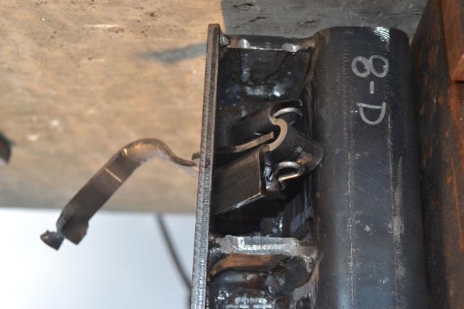
40 26 Figure 19. MWP 8-D Section Details, Test Nos. HTTB-53, HTTB-54, HTTB-59, and HTTB-60
41 27 Figure 20. Reinforced MWP Details for Pinned-Back, Test Nos. HTTB-53, HTTB-54, HTTB-59, and HTTB-60
42 28 Figure 21. Tabbed Bracket with Key Plate Attachment, Test Nos. HTTB-49, HTTB-50, HTTB-55, and HTTB-56
43 29 Figure 22. Tabbed Bracket with Key Plate Attachment Flat Pattern, Test Nos. HTTB-49, HTTB-50, HTTB-55, and HTTB-56
44 30 Figure 23. Tabbed Bracket with Wire Lock Pin, Test Nos. HTTB-51, HTTB-52, HTTB-57, and HTTB-58
45 31 Figure 24. Tabbed Bracket with Wire Pin Lock Flat Pattern, Test Nos. HTTB-51, HTTB-52, HTTB-57, and HTTB-58
46 32 Figure 25. Tabbed Bracket with Pinned Back, Test Nos. HTTB-53, HTTB-54, HTTB-59, and HTTB-60
47 33 Figure 26. Tabbed Bracket with Pinned Back Flat Pattern, Test Nos. HTTB-53, HTTB-54, HTTB-59, and HTTB-60
48 34 Figure 27. Key Plate for Tabbed Bracket with Key Plate Attachment, Test Nos. HTTB-49, HTTB-50, HTTB-55, and HTTB-56
49 35 Figure 28. Wire Lock Pin for Tabbed Bracket with Wire Lock Pin, Test Nos. HTTB-51, HTTB-52, HTTB-57, and HTTB-58
50 36 Figure 29. Pinned Back and Attachment for Tabbed Bracket with Pinned Back, Test Nos. HTTB-53, HTTB-54, HTTB-59, and HTTB- 60
51 37 Figure 30. Bogie Testing Matrix
52 38 Figure 31. Bill of Materials
53 39 Figure 32. Bill of Materials, Continued
54 3 TABBED BRACKET COMPONENT TESTING CONDITIONS 3.1 Purpose Dynamic component testing of the new tabbed bracket attachment designs was conducted to evaluate their performance. Specifically, testing was conducted to obtain the cable release loads in both the vertical and lateral directions. The results were compared to the release loads of the previously tested bolted, tabbed bracket (V10) to evaluate the performance of the new bracket designs for potential use within the non-proprietary high-tension cable barrier system. 3.2 Scope Twelve dynamic component tests were conducted on the new tabbed bracket designs. These tests consisted of attaching one end of a cable to a bogie and looping the other end through the inside of the test article (tabbed bracket). The bracket and cable assembly were mounted to a rigid MWP section, which was contained within the test jig. The test jig linked the MWP section to a load cell and was anchored to a rigid concrete block. A target bogie speed of 5 mph (8 km/h) away from the test article was used to load the cable in tension and dynamically load the new bracket configurations. Loading continued to increase until the cable was released from the bracket. An adjustable plate was used within the jig, which allowed the MWP segment to be rotated between 0 and 90 degrees. Thus, the brackets were loaded in both the vertical and lateral directions, respectively. The key plate, wire lock pin, and pinned-back attachment designs were subjected to two tests in each direction for a total of twelve component tests. The test matrix is shown in Table 2. The load cell data was then analyzed and the results were compared with the bolted tabbed bracket (V10) dynamic test results [2]. 40
55 Table 2. Tabbed Bracket Testing Matrix Test No. Bracket Attachment Design Orientation (deg.) Load Direction HTTB-49 Key Plate 0 Vertical HTTB-50 Key Plate 0 Vertical HTTB-51 Wire Lock Pin 0 Vertical HTTB-52 Wire Lock Pin 0 Vertical HTTB-53 Pinned Back 0 Vertical HTTB-54 Pinned Back 0 Vertical HTTB-55 Key Plate 90 Lateral HTTB-56 Key Plate 90 Lateral HTTB-57 Wire Lock Pin 90 Lateral HTTB-58 Wire Lock Pin 90 Lateral HTTB-59 Pinned Back 90 Lateral HTTB-60 Pinned Back 90 Lateral Target Speed mph (km/h) 5 (8) 5 (8) 5 (8) 5 (8) 5 (8) 5 (8) 5 (8) 5 (8) 5 (8) 5 (8) 5 (8) 5 (8) 3.3 Test Facility Physical testing of the tabbed bracket alternative attachment designs was conducted at the MwRSF outdoor proving grounds, which is located at the Lincoln Air Park on the northwest side of Lincoln Municipal Airport. The facility is approximately 5 miles (8 km) northwest of the University of Nebraska-Lincoln city campus. 41
 load cell, a test jig, high-speed and standard-speed digital video cameras, and still cameras. 3.4.")
56 3.4 Equipment and Instrumentation The equipment and instrumentation that was utilized to collect and record data during the cable-to-post dynamic bogie tests included a bogie vehicle, a 50-kip (222-kN) load cell, a test jig, high-speed and standard-speed digital video cameras, and still cameras Bogie Vehicle A rigid-frame bogie was used to pull the cable that was attached to the various tabbed bracket designs. The weight of the bogie was 1,682 lb (763 kg). A pickup truck was used to propel the bogie along a guidance track to a target speed of 5 mph (8 km/h). The pickup truck braked, allowing the bogie to be free-rolling as it approached the end of the guidance system and applied the load to the cable-to-post attachment. A remote braking system was installed on the bogie, allowing it to be brought safely to rest after the test. The bogie with the test setup is shown in Figure 33. Figure 33. Rigid-Frame Bogie on Guidance Track 42

57 3.4.2 Test Jig A test jig was utilized to support and anchor the test article. The short MWP post selection was bolted to a mounting plate, which could be adjusted to change the angle at which the cable pulled on the post-bracket assembly. A steel rod was used to connect and transfer loads from the mounting plate to the load cell. The steel rod was encased by a cylindrical steel tube to restrict motion to only the direction of loading. A looped cable was placed through the tabbed bracket and through a feeder tube in line with the load cell and mounting plate. The other end of the cable was attached to the bogie. The test jig was mounted to the side of a rigid concrete block, as shown in Figure 34. Figure 34. Test Jig 43
58 3.4.3 Load Cell A 50-kip (222-kN) capacity load cell was used to measure the force exerted on the test article by the cable until the cable was released. This load cell was placed between the mounting plate and a rigid anchor plate and recorded the tensile loads imparted to the tabbed bracket and post assembly Digital Photography Two AOS high speed digital video cameras and one GoPro Hero 3 digital camera were used to document each test. The AOS high-speed cameras had a frame rate of 500 frames per second and the GoPro digital video camera recorded at 120 frames per second. A Nikon D50 digital still camera was also used, to document pre- and post-test conditions for all tests. 3.5 Data Processing and Analysis Force data was measured with the load cell transducer and filtered using the SAE Class 60 Butterworth filter conforming to SAE J211/1 specifications [4]. Once the data was processed, the period of the loading event was determined. Since the tensile load in the cable was gradually increased until the cable was pulled taut, it was often difficult to determine the beginning of loading from the load cell data alone. However, the moment of cable release was easily detectable as the point when the load dropped to zero very rapidly. Thus, high-speed video was utilized to determine the time duration between initial loading and cable release. The load cell data was then cropped to reflect the same time duration. 44
59 4 TABBED BRACKET COMPONENT TESTING 4.1 Results A total of twelve component tests, test nos. HTTB-49 through HTTB-60, were conducted on the three tabbed bracket alternative attachment designs. Each design concept was loaded twice in its vertical orientation and twice in its lateral orientation. The peak forces were obtained from the load cell data, and the behavior of the cable and the bracket was observed from highspeed video. Test results for all load cells are provided in Appendix B Test No. HTTB-49 Test no. HTTB-49 evaluated the tabbed bracket with the key plate attachment by loading the bracket vertically, or at an angle of 0 degrees relative to the face of the post. Once the cable was pulled into tension, the construction tolerances within the key plate connection allowed the bracket to rotate slightly outward. As the load imparted to the tabbed bracket increased, the spine of the bracket began to bend, and the bracket opened. At seconds after the initial loading, a peak load of 0.27 kips (1.20 kn) was reached. After this peak, the force fell quickly as the bracket continued to open. The peak occurring after this time was caused by the cable briefly catching on the tabs after it released from the bracket, a phenomenon possible only because of the cable loop. In an actual installation where the cable is straight, the tabs would not be expected to snag the cable. As such, the forces associated with the snag were not considered part of the release load. The tabs completely exited the keyway by seconds. The force vs. time curve is shown in Figure 35. Pre- and post-test photographs and sequential photographs are shown in Figures 36 and 37, respectively. 45
60 0.3 CFC 60 Load - Extracted HTTB Force (kips) Time (sec) CFC 60 LOAD (kips) Figure 35. Force vs. Time Data, Test No. HTTB-49 46

")


61 47 Figure 36. Pre-Test (Upper) and Post-Test (Lower) Photographs, Test No. HTTB-49
62 48 Time = 0 sec Time = sec Time = sec Time = sec Figure 37. Sequential Photographs, Test No. HTTB-49
63 Force (kips) Test No. HTTB-50 Test no. HTTB-50 evaluated the tabbed bracket with the key plate attachment by loading the bracket vertically, or at an angle of 0 degrees relative to the face of the post. Once the cable was pulled into tension, the construction tolerances within the key plate connection allowed the bracket to rotate slightly outward. As the load imparted to the tabbed bracket increased, the spine of the bracket began to bend, and the bracket opened. At seconds after the initial loading, a peak load of 0.29 kips (1.29 kn) was reached. After this peak, the force fell quickly as the bracket continued to open and the tabs were lifted out of the keyway. The tabs completely exited the keyway at seconds. The force vs. time curve is shown in Figure 38. Pre- and post-test photographs and sequential photographs are shown in Figures 39 and 40, respectively CFC 60 Load - Extracted HTTB Time (sec) CFC 60 LOAD (kips) Figure 38. Force vs. Time Data, Test No. HTTB-50 49

")


64 50 Figure 39. Pre-Test (Upper) and Post-Test (Lower) Photographs, Test No. HTTB-50
65 51 Time = 0 sec Time = sec Time = sec Time = sec Figure 40. Sequential Photographs, Test No. HTTB-50
66 Force (kips) Test No. HTTB-51 Test no. HTTB-51 evaluated the tabbed bracket with the wire lock pin attachment by loading the bracket vertically, or at an angle of 0 degrees relative to the face of the post. Once the cable was pulled into tension, the construction tolerances within the wire lock pin connection allowed the bracket to rotate slightly outward. As the load imparted to the tabbed bracket increased, the spine of the bracket began to bend, and the bracket opened. At seconds after the initial loading, a peak load of 0.26 kips (1.16 kn) was reached. After this peak, the force fell quickly as the bracket continued to open and the tabs were lifted out of the keyway. By seconds, the tabs had completely exited the keyway. The two peaks occurring after this time were caused by the cable briefly catching on the tabs after it released from the bracket and were not considered part of the release load. The force vs. time curve is shown in Figure 41. Pre- and post-test photographs and sequential photographs are shown in Figures 42 and 43, respectively. 0.3 CFC 60 Load - Extracted HTTB Time (sec) CFC 60 LOAD (kips) Figure 41. Force vs. Time Data, Test No. HTTB-51 52

")


67 53 Figure 42. Pre-Test (Upper) and Post-Test (Lower) Photographs, Test No. HTTB-51
68 54 Time = 0 sec Time = sec Time = sec Time = sec Figure 43. Sequential Photographs, Test No. HTTB-51
69 Force (kips) Test No. HTTB-52 Test no. HTTB-52 evaluated the tabbed bracket with the wire lock pin attachment when loaded vertically, or at an angle of 0 degrees relative to the face of the post. Once the cable was pulled into tension, the construction tolerances within the wire lock pin connection allowed the bracket to rotate slightly outward. As the load imparted to the tabbed bracket increased, the spine of the bracket began to bend, and the bracket opened. At seconds after the initial loading, a peak load of 0.79 kips (3.51 kn) was reached. Installation tolerances allowed the bracket to twist and the tabs to catch on the side of the keyway for a short time before releasing at seconds. After this, the force fell quickly as the bracket continued to open and the tabs were lifted out of the keyway. After the tab released from its snagged position on the keyway, bracket flexure and snag on the cable produced loads similar to the previous vertical release loads with a peak load of 0.25 kips (1.11 kn). The force vs. time curve is shown in Figure 44. Pre- and post-test photographs and sequential photographs are shown in Figures 45 and 46, respectively. 0.9 CFC 60 Load - Extracted HTTB Time (sec) CFC 60 LOAD (kips) Figure 44. Force vs. Time Data, Test No. HTTB-52 55

")


70 56 Figure 45. Pre-Test (Upper) and Post-Test (Lower) Photographs, Test No. HTTB-52
71 57 Time = 0 sec Time = sec Time = sec Time = sec Figure 46. Sequential Photographs, Test No. HTTB-52
72 Force (kips) Test No. HTTB-53 Test no. HTTB-53 evaluated the tabbed bracket with the pinned-back attachment by loading the bracket vertically, or at an angle of 0 degrees relative to the face of the post. Once the cable was pulled into tension, the construction tolerances within the pinned-back connection allowed the bracket to rotate slightly outward. As the load imparted to the tabbed bracket increased, the spine of the bracket began to bend, and the bracket opened. At seconds after the initial loading, a peak load of 0.28 kips (1.25 kn) was reached. After this peak, the force fell quickly as the bracket continued to open and the tabs were lifted out of the keyway. By seconds, the tabs had completely exited the keyway. The two peaks occurring after this time were caused by the cable briefly catching on the tabs after it released from the bracket and were not considered part of the release load. The force vs. time curve is shown in Figure 47. Pre- and post-test photographs and sequential photographs are shown in Figures 48 and 49, respectively. 0.3 CFC 60 Load - Extracted HTTB Time (sec) CFC 60 LOAD (kips) Figure 47. Force vs. Time Data, Test No. HTTB-53 58

")


73 59 Figure 48. Pre-Test (Upper) and Post-Test (Lower) Photographs, Test No. HTTB-53
74 60 Time = 0 sec Time = sec Time = sec Time = sec Figure 49. Sequential Photographs, Test No. HTTB-53
75 Force (kips) Test No. HTTB-54 Test no. HTTB-54 evaluated the tabbed bracket with the pinned-back attachment by loading the bracket vertically, or at an angle of 0 degrees relative to the face of the post. Once the cable was pulled into tension, the construction tolerances within the pinned-back connection allowed the bracket to rotate slightly outward. As the load imparted to the tabbed bracket increased, the spine of the bracket began to bend, and the bracket opened. At seconds after the initial loading, a peak load of 0.29 kips (1.29 kn) was reached. By seconds, the bracket had completely released the cable. The force vs. time curve is shown in Figure 50. Pre- and posttest photographs and sequential photographs are shown in Figures 51 and 52, respectively CFC 60 Load - Extracted HTTB Time (sec) CFC 60 LOAD (kips) Figure 50. Force vs. Time Data, Test No. HTTB-54 61

")


76 62 Figure 51. Pre-Test (Upper) and Post-Test (Lower) Photographs, Test No. HTTB-54

77 63 Time = 0 sec Time = sec Time = sec Time = sec Figure 52. Sequential Photographs, Test No. HTTB-54
78 Force (kips) Test No. HTTB-55 Test no. HTTB-55 evaluated the tabbed bracket with the key plate attachment by loading the bracket laterally, or normal to the flange of the post. As the cable was pulled into tension, the tabs were pulled against the post flange at the bottom of the keyway. As the load increased, the spine of the bracket began to bend and stretch. At seconds, a peak load of 4.77 kips (21.22 kn) was reached and bending of the tabs resulted in the tabs being pulled through the keyway. By seconds, the tabs had completely exited the keyway. The spine of the bracket bent open, and the cable was released at seconds. The force vs. time curve is shown in Figure 53. Pre- and post-test photographs and sequential photographs are shown in Figures 54 and 55, respectively. 6 CFC 60 Load - Extracted HTTB Time (sec) CFC 60 LOAD (kips) Figure 53. Force vs. Time Data, Test No. HTTB-55 64

")


79 65 Figure 54. Pre-Test (Upper) and Post-Test (Lower) Photographs, Test No. HTTB-55


80 66 Time = 0 sec Time = sec Time = sec Time = sec Figure 55. Sequential Photographs, Test No. HTTB-55
81 Force (kips) Test No. HTTB-56 Test no. HTTB-56 evaluated the tabbed bracket with the key plate attachment by loading the bracket laterally, or normal to the flange of the post. As the cable was pulled into tension, the tabs were pulled against the post flange at the bottom of the keyway. As the load increased, the spine of the bracket began to bend and stretch. At seconds, the spine continued to bend, causing the tabs to rotate out of the keyway without ever catching on the keyway. At seconds, a peak load of 0.41 kips (1.82 kn) was reached. The remaining force peaks were caused by further bending of the spine before the cable was released. The cable was completely released from the bracket at seconds after initial loading. The force vs. time curve is shown in Figure 56. Pre- and post-test photographs and sequential photographs are shown in Figures 57 and 58, respectively CFC 60 Load - Extracted HTTB Time (sec) CFC 60 LOAD (kips) Figure 56. Force vs. Time Data, Test No. HTTB-56 67

")


82 68 Figure 57. Pre-Test (Upper) and Post-Test (Lower) Photographs, Test No. HTTB-56

83 69 Time = 0 sec Time = sec Time = sec Time = sec Figure 58. Sequential Photographs, Test No. HTTB-56
84 Force (kips) Test No. HTTB-57 Test no. HTTB-57 evaluated the tabbed bracket with the wire lock pin attachment by loading the bracket laterally, or normal to the flange of the post. As the cable was pulled into tension, the tabs were pulled against the post flange at the bottom of the keyway. As the load increased, the spine of the bracket began to bend and stretch. At seconds, a peak load of 6.59 kips (29.31 kn) was reached. The tabs sheared off while exiting the keyway at seconds. The cable was fully released from the bracket at seconds. The force vs. time curve is shown in Figure 59. Pre- and post-test photographs and sequential photographs are shown in Figures 60 and 61, respectively. 7 CFC 60 Load - Extracted HTTB Time (sec) CFC 60 LOAD (kips) Figure 59. Force vs. Time Data, Test No. HTTB-57 70

")


85 71 Figure 60. Pre-Test (Upper) and Post-Test (Lower) Photographs, Test No. HTTB-57
86 72 Time = 0 sec Time = sec Time = sec Time = sec Figure 61. Sequential Photographs, Test No. HTTB-57
87 Force (kips) Test No. HTTB-58 Test no. HTTB-58 evaluated the tabbed bracket with the wire lock pin attachment by loading the bracket laterally, or normal to the flange of the post. As the cable was pulled into tension, the tabs were pulled against the post flange at the bottom of the keyway. As the load increased, the spine of the bracket began to bend and stretch. The tabs may not have been fully engaged with the keyway as a peak load of 3.50 kips (15.57 kn) was reached at seconds. At this time, the tab edges sheared and the bracket exited the keyway at seconds. The cable was fully released from the bracket at seconds. The force vs. time curve is shown in Figure 62. Pre- and post-test photographs and sequential photographs are shown in Figures 63 and 64, respectively. 4 CFC 60 Load - Extracted HTTB Time (sec) CFC 60 LOAD (kips) Figure 62. Force vs. Time Data, Test No. HTTB-58 73

")


88 74 Figure 63. Pre-Test (Upper) and Post-Test (Lower) Photographs, Test No. HTTB-58

89 75 Time = 0 sec Time = sec Time = sec Time = sec Figure 64. Sequential Photographs, Test No. HTTB-58
90 Force (kips) Test No. HTTB-59 Test no. HTTB-59 evaluated the tabbed bracket with the pinned-back attachment by loading the bracket laterally, or normal to the flange of the post. As the cable was pulled into tension, the tabs were pulled against the post flange at the bottom of the keyway. As the load increased, the spine of the bracket began to bend and stretch. At seconds, a peak load of 6.24 kips (27.76 kn) was reached. The bracket continued to bend and stretch but never fractured or released from the keyway. Instead, the bogie vehicle was brought to a stop, and the load ended at seconds. Because the tabs never released, the actual failure load would be greater than the recorded peak. The force vs. time curve is shown in Figure 65. Pre- and post-test photographs and sequential photographs are shown in Figures 66 and 67, respectively. 7 CFC 60 Load - Extracted HTTB Time (sec) CFC 60 LOAD (kips) Figure 65. Force vs. Time Data, Test No. HTTB-59 76

")


91 77 Figure 66. Pre-Test (Upper) and Post-Test (Lower) Photographs, Test No. HTTB-59

92 78 Time = 0 sec Time = sec Time = sec Time = sec Figure 67. Sequential Photographs, Test No. HTTB-59
93 Force (kips) Test No. HTTB-60 Test no. HTTB-60 evaluated the tabbed bracket with the pinned-back attachment by loading the bracket laterally, or normal to the flange of the post. As the cable was pulled into tension, the tabs were pulled against the post flange at the bottom of the keyway. As the load increased, the spine of the bracket began to bend and stretch. At seconds, a peak load of 6.84 kips (30.43 kn) was reached. The tabs sheared off while exiting the keyway shortly after this peak was reached. The force vs. time curve is shown in Figure 68. Pre- and post-test photographs and sequential photographs are shown in Figures 69 and 70, respectively. Due to a faulty trigger, the AOS high-speed digital video camera failed to record the test. Thus, video from a GoPro Hero 3 digital camera was used for sequential photographs. 8 CFC 60 Load - Extracted HTTB Time (sec) CFC 60 LOAD (kips) Figure 68. Force vs. Time Data, Test No. HTTB-60 79


")


94 Figure 69. Pre-Test (Upper) and Post-Test (Lower) Photographs, Test No. HTTB-60 80

95 Time = 0 sec Time = sec Time = sec Figure 70. Sequential Photographs, Test No. HTTB-60 81
96 4.2 Discussion Twelve dynamic component tests were performed to evaluate three alternative attachment designs that simplified the installation process of the bolted, tabbed bracket (V10). Two vertical and two lateral load tests were conducted on each attachment design. A summary of the tabbed bracket component testing results is shown in Table 3. Previous test results of the bolted, tabbed bracket (V10) were added to the table to allow for direct comparisons [2]. These previous tests are highlighted to avoid confusion with the component tests conducted herein. All six of the brackets loaded in the vertical direction released the cable after the bracket bent, and the tabs rotated out of the upper portion of the keyway, as expected. However, one of the vertical load tests, test no. HTTB-52 with the wire lock pin attachment, exceeded the desired maximum force of 400 lb (1.8 kn). During test no. HTTB-52, the bracket twisted, and the tabs snagged on the side of the keyway. This behavior was not expected nor desired, and caused the peak force to increase to 790 lb (3.5 kn), more than double the targeted value. This behavior was attributed to a loose connection between the bracket and the post segment resulting from construction tolerances and limited fixity in the connection. The connection ultimately allowed the bracket to twist prior to being loaded. All other vertical tests resulted in the bracket tabs releasing through the keyway, and peak loads ranged between 260 lb and 290 lb (1.2 and 1.3 kn). The release/failure mechanism observed in the lateral load tests was variable, as shown in Figures 71 and 72. Two lateral tests resulted in the tabs rotating out of the keyway, a release mechanism not desired for lateral loads. Three of the tests resulted in the tabs tearing just prior to cable release, one of three failure mechanisms of the original bolted, tabbed bracket (V10). Due to the variable release mechanisms, the lateral load tests produced rather inconsistent release loads, and only half of the tests produced release loads above the 6-kip (27-kN) design value. 82
97 83 The key plate attachment brackets both released prior to achieving the targeted lateral load. During test no. HTTB-55 the tabs caught in the keyway and sheared off, one of the intended failure modes. However, a maximum load of only 4.77 kips (21.2 kn) was observed, well short of the desired 6 kips (27 kn). This outcome may be a result of the lack of fixity in the bracket-to-post connection that allowed the bracket to rotate slightly prior to loading of the bracket. This rotation could have resulted in the tabs being loaded out of plane and introducing Mode III fracture where there was previously only Mode II. The lack of fixity in the connection was also thought to contribute to unexpected release of the tabs in test no. HTTB-56 when the bracket opened up without the tabs ever catching on the keyway and resulted in a very low release load of 0.41 kips (1.8 kn). The wire lock pin bracket tests produced lateral release loads of 6.59 kips and 3.50 kips (29.3 kn and 15.6 kn). The low release load, obtained during test no. HTTB-58, did not fully engage the keyway and the tabs slipped out prior to their failure. Similar to the key plate attachment, a lack of fixity in the connection was thought to be responsible for the unexpected release of the tabs through the keyway. Both of the pinned-back brackets produced lateral release loads above the 6-kip (27-kN) design value. Interestingly, during test no. HTTB-59, the bracket never released the cable, and the bogie was brought to a stop. Thus, the actual failure load for that bracket would be greater than the maximum recorded force of 6.25 kips (27.8 kn). However, the connection design still resulted in a lack of fixity and a lot of allowable movement of the bracket prior to loading. Thus, a concern for potential unexpected failures similar to the other two designs still exists. In general, all three of the alternative attachment designs for the tabbed brackets resulted in loose connections that allowed each bracket some wiggle room after attached. This freedom to rotate and translate slightly while attached to the post resulted in a variable pre-test location of
98 the tabs within the keyway, as shown Figures 73 and 74. Throughout the testing and evaluation of these tabbed brackets, both herein and during previous phases [2-3], the performance of the brackets was sensitive to the initial location of the tabs within the keyway. Thus, the alternative attachment brackets continued to demonstrate more variable results than the bolted, tabbed brackets where the bracket is fixed to the post. Table 3. Tabbed Bracket Dynamic Testing Results Test Bracket Load Load Direction kips (kn) Failure HTTB-37 Bolted - V10 Vertical 0.42 (1.86) Tab release through keyway. HTTB-38 Bolted - V10 Vertical 0.27 (1.21) Tab release through keyway HTTB-49 Key Plate Vertical 0.27 (1.20) Tab release through keyway HTTB-50 Key Plate Vertical 0.29 (1.29) Tab release through keyway HTTB-51 Wire Lock 0.26 Vertical Pin (1.16) Tab release through keyway HTTB-52 Wire Lock 0.79 Tab release through keyway (snag on upper Vertical Pin (3.51) part of keyway) HTTB-53 Pinned Back Vertical 0.28 (1.25) Tab release through keyway HTTB-54 Pinned Back Vertical 0.29 (1.29) Tab release through keyway HTTB-31 Bolted - V10 Lateral 6.03 (26.82) Fracture around bolt hole HTTB-32 Bolted - V10 Lateral 6.17 (27.45) Fracture through bracket spine HTTB-55 Key Plate Lateral 4.77 (21.22) Bending and tearing of tabs HTTB-56 Key Plate Lateral 0.41 Tabs rotated up and through keyway tabs (1.82) never caught HTTB-57 Wire Lock 6.59 Lateral Pin (29.31) Tearing off of tabs HTTB-58 Wire Lock 3.50 Minor tab deformation tabs released Lateral Pin (15.57) through keyway HTTB-59 Pinned Back Lateral 6.24 (27.76) No failure stopped bogie HTTB-60 Pinned Back Lateral 6.84 (30.43) Tearing off of tabs Bolted, tabbed bracket (V10) test results from previous study [2] 84


99 85 Bolted Bracket Key Plate Bracket Figure 71. Lateral Test Fracture/Failure Mechanisms for Bolted Bracket and Key Plate Bracket Designs


100 86 Wire Lock Pin Bracket Pinned Back Bracket Figure 72. Lateral Test Fracture/Failure Mechanisms for Wire Lock Pin Bracket and Pinned-Back Bracket Designs


101 Vertical Bolted Bracket Lateral Vertical Key Plate Bracket Lateral Figure 73. Pre-Test Tab Locations for Bolted Brackets and Key Plate Brackets 87


102 Vertical Wire Lock Pin Bracket Lateral Vertical Pinned-Back Bracket Lateral Figure 74. Pre-Test Tab Locations for Wire Lock Pin Brackets and Pinned-Back Brackets 88
Continued Development of a Non-Proprietary, High-Tension, Cable End Terminal System
 University of Nebraska - Lincoln DigitalCommons@University of Nebraska - Lincoln Nebraska Department of Transportation Research Reports Nebraska LTAP 4-29-2016 Continued Development of a Non-Proprietary,
INCREASED SPAN LENGTH FOR THE MGS LONG-SPAN GUARDRAIL SYSTEM PART III: FAILURE ANALYSIS
 Midwest States Pooled Fund Research Program Fiscal Years 2013 (Years 23) Research Project Number TPF-5(193) Supplement #56 NDOR Sponsoring Agency Code RPFP-13-MGS-3 INCREASED SPAN LENGTH FOR THE MGS LONG-SPAN
TEST MATRICES FOR EVALUATING CABLE MEDIAN BARRIERS PLACED IN V-DITCHES
 Midwest States Regional Pooled Fund Research Program Fiscal Year 2012 (Year 22) Research Project Number TPF-5(193) Supplement #44 NDOR Sponsoring Agency Code RPFP-12-CABLE1&2 TEST MATRICES FOR EVALUATING
DEVELOPMENT OF A TRANSITION BETWEEN FREE-STANDING AND REDUCED-DEFLECTION PORTABLE CONCRETE BARRIERS PHASE I
 Research Project Number TPF-5(193) Supplement #78 DEVELOPMENT OF A TRANSITION BETWEEN FREE-STANDING AND REDUCED-DEFLECTION PORTABLE CONCRETE BARRIERS PHASE I Submitted by Mojdeh Asadollahi Pajouh, Ph.D.
DEFLECTION LIMITS FOR TEMPORARY CONCRETE BARRIERS
 Midwest State s Regional Pooled Fund Research Program Fiscal Year 1998-1999 (Year 9) NDOR Research Project Number SPR-3(017) DEFLECTION LIMITS FOR TEMPORARY CONCRETE BARRIERS Submitted by Dean L. Sicking,
PR V2. Submitted by. Professor MIDWEST Vine Street (402) Submitted to
 Submitted to") FINAL REPORT PR4893118-V2 ZONE OF INTRUSION STUDY Submitted by John D. Reid, Ph.D. Professor Dean L.. Sicking, Ph.D., P.E. Professorr and MwRSF Director MIDWEST ROADSIDE SAFETY FACILITY University of Nebraska-Lincoln
FINAL REPORT PR4893118-V2 ZONE OF INTRUSION STUDY Submitted by John D. Reid, Ph.D. Professor Dean L.. Sicking, Ph.D., P.E. Professorr and MwRSF Director MIDWEST ROADSIDE SAFETY FACILITY University of Nebraska-Lincoln
John Rohde, Ph.D., P.E. Associate Professor Department of Civil Engineering University of Nebraska-Lincoln
 Report # MATC-UNL: 222 Final Report 25-1121-1-222 Development of a Socketed Foundation for Cable Barrier Posts - Phase I John Rohde, Ph.D., P.E. Associate Professor Department of Civil Engineering University
Development of a TL-5 Vertical Faced Concrete Median Barrier Incorporating Head Ejection Criteria
 Midwest States Regional Pooled Fund Research Program Fiscal Year 2004-2005 (Year 15) Research Project Number SPR-3(017) NDOR Sponsoring Agency Code RPFP-05-01 Development of a TL-5 Vertical Faced Median
EXTENDING TL-2 SHORT-RADIUS GUARDRAIL TO LARGER RADII
 Research Project Number TPF-5(193) Supplement 27 EXTENDING TL-2 SHORT-RADIUS GUARDRAIL TO LARGER RADII Submitted by Cody S. Stolle, Ph.D., E.I.T. Post-Doctoral Research Associate Robert W. Bielenberg,
Midwest Guardrail System Without Blockouts
 Duplication for publication or sale is strictly prohibited without prior written permission of the Transportation Research Board Paper No. 13-0418 Midwest Guardrail System Without Blockouts by John D.
Development and Implementation of the Simplified MGS Stiffness Transition
 Duplication for publication or sale is strictly prohibited without prior written permission of the Transportation Research Board Paper No. 12-3367 Development and Implementation of the Simplified MGS Stiffness
Research Project Number SPR-P1(13)M326 DEVELOPMENT OF A MASH TL-3 TRANSITION BETWEEN GUARDRAIL AND PORTABLE CONCRETE BARRIERS.
M326 DEVELOPMENT OF A MASH TL-3 TRANSITION BETWEEN GUARDRAIL AND PORTABLE CONCRETE BARRIERS.") Research Project Number SPR-P1(13)M326 DEVELOPMENT OF A MASH TL-3 TRANSITION BETWEEN GUARDRAIL AND PORTABLE CONCRETE BARRIERS Submitted by David A. Gutierrez, B.S.C.E., E.I.T. Graduate Research Assistant
Research Project Number SPR-P1(13)M326 DEVELOPMENT OF A MASH TL-3 TRANSITION BETWEEN GUARDRAIL AND PORTABLE CONCRETE BARRIERS Submitted by David A. Gutierrez, B.S.C.E., E.I.T. Graduate Research Assistant
CRITICAL FLARE RATES FOR W-BEAM GUARDRAIL DETERMINING MAXIMUM CAPACITY USING COMPUTER SIMULATION NCHRP 17-20(3)
") CRITICAL FLARE RATES FOR W-BEAM GUARDRAIL DETERMINING MAXIMUM CAPACITY USING COMPUTER SIMULATION NCHRP 17-2(3) Submitted by Beau D. Kuipers, B.S.M.E., E.I.T. Graduate Research Assistant Ronald K. Faller,
CRITICAL FLARE RATES FOR W-BEAM GUARDRAIL DETERMINING MAXIMUM CAPACITY USING COMPUTER SIMULATION NCHRP 17-2(3) Submitted by Beau D. Kuipers, B.S.M.E., E.I.T. Graduate Research Assistant Ronald K. Faller,
Evaluation of the Midwest Guardrail System Stiffness Transition with Curb
 Duplication for publication or sale is strictly prohibited without prior written permission of the Transportation Research Board Paper No. -0 Evaluation of the Midwest Guardrail System Stiffness Transition
DEVELOPMENT OF A MASH TL-3 TRANSITION BETWEEN GUARDRAIL AND PORTABLE CONCRETE BARRIERS
 Duplication for publication or sale is strictly prohibited without prior written permission of the Transportation Research Board Paper No. 17-01712 DEVELOPMENT OF A MASH TL-3 TRANSITION BETWEEN GUARDRAIL
Evaluation of the Midwest Guardrail System stiffness transition with curb
 University of Nebraska - Lincoln DigitalCommons@University of Nebraska - Lincoln Civil Engineering Faculty Publications Civil Engineering 2016 Evaluation of the Midwest Guardrail System stiffness transition
SAFETY PERFORMANCE OF WORK-ZONE DEVICES UNDER MASH TESTING
 SAFETY PERFORMANCE OF WORK-ZONE DEVICES UNDER MASH TESTING Schmidt, Faller, Lechtenberg, Sicking, Holloway Midwest Roadside Safety Facility Nebraska Transportation Center University of Nebraska-Lincoln
Analysis of Existing Work-Zone Sign Supports Using Manual for Assessing Safety Hardware Safety Performance Criteria
 University of Nebraska - Lincoln DigitalCommons@University of Nebraska - Lincoln Civil Engineering Faculty Publications Civil Engineering 2011 Analysis of Existing Work-Zone Sign Supports Using Manual
MINIMUM EFFECTIVE LENGTH FOR THE MIDWEST GUARDRAIL SYSTEM
 Duplication for publication or sale is strictly prohibited without prior written permission of the Transportation Research Board Paper No. 15-0484 MINIMUM EFFECTIVE LENGTH FOR THE MIDWEST GUARDRAIL SYSTEM
PERFORMANCE EVALUATION OF THE FREE-STANDING TEMPORARY BARRIER UPDATE TO NCHRP 350 TEST NO (2214TB-1)
") PERFORMANCE EVALUATION OF THE FREE-STANDING TEMPORARY BARRIER UPDATE TO NCHRP 350 TEST NO. 3-11 (2214TB-1) Submitted by Karla A. Polivka, M.S.M.E., E.I.T. Research Associate Engineer Dean L. Sicking, Ph.D.,
PERFORMANCE EVALUATION OF THE FREE-STANDING TEMPORARY BARRIER UPDATE TO NCHRP 350 TEST NO. 3-11 (2214TB-1) Submitted by Karla A. Polivka, M.S.M.E., E.I.T. Research Associate Engineer Dean L. Sicking, Ph.D.,
PERFORMANCE EVALUATION OF THE FREE-STANDING TEMPORARY BARRIER UPDATE TO NCHRP 350 TEST NO WITH 28" C.G. HEIGHT (2214TB-2)
") PERFORMANCE EVALUATION OF THE FREE-STANDING TEMPORARY BARRIER UPDATE TO NCHRP 350 TEST NO. 3-11 WITH 28" C.G. HEIGHT (2214TB-2) Submitted by Karla A. Polivka, M.S.M.E., E.I.T. Research Associate Engineer
PERFORMANCE EVALUATION OF THE FREE-STANDING TEMPORARY BARRIER UPDATE TO NCHRP 350 TEST NO. 3-11 WITH 28" C.G. HEIGHT (2214TB-2) Submitted by Karla A. Polivka, M.S.M.E., E.I.T. Research Associate Engineer
PERFORMANCE EVALUATION OF THE PERMANENT NEW JERSEY SAFETY SHAPE BARRIER UPDATE TO NCHRP 350 TEST NO (2214NJ-2)
") PERFORMANCE EVALUATION OF THE PERMANENT NEW JERSEY SAFETY SHAPE BARRIER UPDATE TO NCHRP 350 TEST NO. 4-12 (2214NJ-2) Submitted by Karla A. Polivka, M.S.M.E., E.I.T. Research Associate Engineer Dean L.
PERFORMANCE EVALUATION OF THE PERMANENT NEW JERSEY SAFETY SHAPE BARRIER UPDATE TO NCHRP 350 TEST NO. 4-12 (2214NJ-2) Submitted by Karla A. Polivka, M.S.M.E., E.I.T. Research Associate Engineer Dean L.
Manual for Assessing Safety Hardware
 American Association of State Highway and Transportation Officials Manual for Assessing Safety Hardware 2009 vii PREFACE Effective traffic barrier systems, end treatments, crash cushions, breakaway devices,
Development of a Moving Automatic Flagger Assistance Device (AFAD) for Moving Work Zone Operations
 for Moving Work Zone Operations") Development of a Moving Automatic Flagger Assistance Device (AFAD) for Moving Work Zone Operations Edward F. Terhaar, Principal Investigator Wenck Associates, Inc. March 2017 Research Project Final Report
Development of a Moving Automatic Flagger Assistance Device (AFAD) for Moving Work Zone Operations Edward F. Terhaar, Principal Investigator Wenck Associates, Inc. March 2017 Research Project Final Report
PERFORMANCE EVALUATION OF THE MODIFIED G4(1S) GUARDRAIL UPDATE TO NCHRP 350 TEST NO WITH 28" C.G. HEIGHT (2214WB-2)
 GUARDRAIL UPDATE TO NCHRP 350 TEST NO WITH 28 C.G. HEIGHT (2214WB-2)") PERFORMANCE EVALUATION OF THE MODIFIED G4(1S) GUARDRAIL UPDATE TO NCHRP 350 TEST NO. 3-11 WITH 28" C.G. HEIGHT (2214WB-2) Submitted by Karla A. Polivka, M.S.M.E., E.I.T. Research Associate Engineer Dean
PERFORMANCE EVALUATION OF THE MODIFIED G4(1S) GUARDRAIL UPDATE TO NCHRP 350 TEST NO. 3-11 WITH 28" C.G. HEIGHT (2214WB-2) Submitted by Karla A. Polivka, M.S.M.E., E.I.T. Research Associate Engineer Dean
SGR52 TOP-MOUNTED WEAK-POST GUARDRAIL ATTACHED TO CULVERT PLAN VIEW ELEVATION VIEW DETAIL B DETAIL A SHEET NO. DATE: 37 1/2" 953 (TYP) 150" 3810
 150 3810") PLAN VIEW C 150" 3810 37 1/2" 953 (TYP) A B C 8-FBB01 RWB01a FWR01 RWM04a FWR01 RWB01a RWM04a PSF01 FBX08a PSF01 FBX08a DETAIL A DETAIL B 1 of 7 12/5/2016 INTENDED USE The Top-Mounted Weak-Post Guardrail
PLAN VIEW C 150" 3810 37 1/2" 953 (TYP) A B C 8-FBB01 RWB01a FWR01 RWM04a FWR01 RWB01a RWM04a PSF01 FBX08a PSF01 FBX08a DETAIL A DETAIL B 1 of 7 12/5/2016 INTENDED USE The Top-Mounted Weak-Post Guardrail
KENTUCKY TRANSPORTATION CENTER
 Research Report KTC-08-10/UI56-07-1F KENTUCKY TRANSPORTATION CENTER EVALUATION OF 70 MPH SPEED LIMIT IN KENTUCKY OUR MISSION We provide services to the transportation community through research, technology
CRASH TEST OF MILE POST MARKER. T. J. Hirsch Research Engineer. and. Eugene Buth Assistant Research Engineer. Research Report Number 146-8
 CRASH TEST OF MILE POST MARKER by T. J. Hirsch Research Engineer and Eugene Buth Assistant Research Engineer Research Report Number 146-8 Studies of Field Adaption of Impact Attenuation Systems Research
FHWA/IN/JTRP-2000/23. Final Report. Sedat Gulen John Nagle John Weaver Victor Gallivan
 FHWA/IN/JTRP-2000/23 Final Report DETERMINATION OF PRACTICAL ESALS PER TRUCK VALUES ON INDIANA ROADS Sedat Gulen John Nagle John Weaver Victor Gallivan December 2000 Final Report FHWA/IN/JTRP-2000/23 DETERMINATION
July 10, Refer to: HSA-10/CC-78A
 July 10, 2003 Refer to: HSA-10/CC-78A Barry D. Stephens, P.E. Senior Vice President of Engineering ENERGY ABSORPTION Systems, Inc. 3617 Cincinnati Avenue Rocklin, California 95765 Dear Mr. Stephens: Your
The University of Texas at Arlington The University of Texas System Texas Transportation Institute The Texas A&M University System
 1. Report No. FHWA/TX-08/5-4385-01-1 4. Title and Subtitle PILOT IMPLEMENTATION OF BUMP DETECTION PROFILER Technical Report Documentation Page 2. Government Accession No. 3. Recipient's Catalog No. 5.
Update to NCHRP Report 350. Current Safety Issues
 Workshop on the Update to NCHRP Report 350 and Current Safety Issues July 18 21, 2004 Sponsored by TRB COMMITTEE AFB20 ROADSIDE SAFETY DESIGN DoubleTree Hotel Overland Park-Corporate Woods 10100 College
Development of Turning Templates for Various Design Vehicles
 Transportation Kentucky Transportation Center Research Report University of Kentucky Year 1991 Development of Turning Templates for Various Design Vehicles Kenneth R. Agent Jerry G. Pigman University of
1962: HRCS Circular 482 one-page document, specified vehicle mass, impact speed, and approach angle for crash tests.
 1 2 3 1962: HRCS Circular 482 one-page document, specified vehicle mass, impact speed, and approach angle for crash tests. 1973: NCHRP Report 153 16-page document, based on technical input from 70+ individuals
REPORT NO. TR-P NC SAFETY COMPLIANCE TESTING FOR FMVSS 223 REAR IMPACT GUARDS 2007 TRANSFREIGHT TECHNOLOGY NHTSA NO.
 REPORT NO. SAFETY COMPLIANCE TESTING FOR FMVSS 223 REAR IMPACT GUARDS 2007 TRANSFREIGHT TECHNOLOGY NHTSA NO. RIG 009 PREPARED BY: KARCO ENGINEERING, LLC. 9270 HOLLY ROAD ADELANTO, CALIFORNIA 92301 SEPTEMBER
Guardrail/Bridgerail Recommendations for Very Low Volume Local Roads in Kansas
 Guardrail/Bridgerail Recommendations for Very Low Volume Local Roads in Kansas MINK Conference September 20, 2017 Ronald J. Seitz, P.E. and Tod Salfrank The Problem The Local Road System in Kansas is Very
NTC. Cable Median Barrier Failure Analysis and Prevention
 Nebraska Transportation Center Report # TRP-03-275-12 Final Report 25-1121-0001-428 Cable Median Barrier Failure Analysis and Prevention Dean L. Sicking, Ph.D., P.E. Professor Department of Civil Engineering
AASHTO Manual for Assessing Safety Hardware, AASHTO/FHWA Joint Implementation Plan Standing Committee on Highways September 24, 2015
 AASHTO Manual for Assessing Safety Hardware, 2015 AASHTO/FHWA Joint Implementation Plan Standing Committee on Highways September 24, 2015 Full Scale MASH Crash Tests (NCHRP 22-14(02)) Conducted several
SAFETY COMPLIANCE TESTING FOR FMVSS 202a Head Restraints
 FINAL REPORT NUMBER 202a-MGA-10-003 SAFETY COMPLIANCE TESTING FOR FMVSS 202a FORD MOTOR COMPANY 2010 Lincoln MKT MPV NHTSA No. CA0213 MGA RESEARCH CORPORATION 446 Executive Drive Troy, Michigan 48083 Test
RELATIVE COSTS OF DRIVING ELECTRIC AND GASOLINE VEHICLES
 SWT-2018-1 JANUARY 2018 RELATIVE COSTS OF DRIVING ELECTRIC AND GASOLINE VEHICLES IN THE INDIVIDUAL U.S. STATES MICHAEL SIVAK BRANDON SCHOETTLE SUSTAINABLE WORLDWIDE TRANSPORTATION RELATIVE COSTS OF DRIVING
TRAFFIC SIMULATION IN REGIONAL MODELING: APPLICATION TO THE INTERSTATEE INFRASTRUCTURE NEAR THE TOLEDO SEA PORT
 MICHIGAN OHIO UNIVERSITY TRANSPORTATION CENTER Alternate energy and system mobility to stimulate economic development. Report No: MIOH UTC TS41p1-2 2012-Final TRAFFIC SIMULATION IN REGIONAL MODELING: APPLICATION
SFI SPECIFICATION 35.2 EFFECTIVE: DECEMBER 29, 2014 *
 SFI SPECIFICATION 35.2 EFFECTIVE: DECEMBER 29, 2014 * PRODUCT: Heavy Duty Stock Car Steel Wheels 1.0 GENERAL INFORMATION 1.1 This SFI Specification establishes uniform test procedures and minimum standards
D-25 Speed Advisory System
 Report Title Report Date: 2002 D-25 Speed Advisory System Principle Investigator Name Pesti, Geza Affiliation Texas Transportation Institute Address CE/TTI, Room 405-H 3135 TAMU College Station, TX 77843-3135
Crash Testing Growth Common Roadside Hardware Systems Draft FHWA and AASHTO Requirements for Implementing MASH 2015
 64 th Annual Illinois Traffic Safety and Engineering Conference October 14, 2015 Crash Testing Growth Common Roadside Hardware Systems Draft FHWA and AASHTO Requirements for Implementing MASH 2015 1 https://www.youtube.com/watch?feature
FAA T53-L-13L Turbine Fragment Containment Test
 DOT/FAA/AR-98/22 Office of Aviation Research Washington, D.C. 20591 FAA T53-L-13L Turbine Fragment Containment Test Appro- June 1998 Final Report This document is available to the U.S. public through the
Heating Comparison of Radial and Bias-Ply Tires on a B-727 Aircraft
 'S Heating Comparison of Radial and Bias-Ply Tires on a B-727 Aircraft November 1997 DOT/FAA/AR-TN97/50 This document is available to the U.S. public through the National Technical Information Service
Improving Roadside Safety by Computer Simulation
 A2A04:Committee on Roadside Safety Features Chairman: John F. Carney, III, Worcester Polytechnic Institute Improving Roadside Safety by Computer Simulation DEAN L. SICKING, University of Nebraska, Lincoln
Control of Pavement Smoothness in Kansas
 Report No. FHWA-KS-8-5 Final REPORT Control of Pavement Smoothness in Kansas William H. Parcells, Jr., P.E. Kansas Department of Transportation Topeka, Kansas May 29 KANSAS DEPARTMENT OF TRANSPORTATION
REPORT NUMBER: 301-CAL SAFETY COMPLIANCE TESTING FOR FMVSS 301 FUEL SYSTEM INTEGRITY REAR IMPACT FORD MOTOR COMPANY 2009 FORD F150 2-DOOR PICKUP
 REPORT NUMBER: 301-CAL-09-03 SAFETY COMPLIANCE TESTING FOR FMVSS 301 FUEL SYSTEM INTEGRITY REAR IMPACT FORD MOTOR COMPANY 2009 FORD F150 2-DOOR PICKUP NHTSA NUMBER: C90206 CALSPAN TRANSPORTATION SCIENCES
800 Access Control, R/W Use Permits and Drive Design
 Table of Contents 801 Access Control... 8-1 801.1 Access Control Directives... 8-1 801.2 Access Control Policies... 8-1 801.2.1 Interstate Limited Access... 8-1 801.2.2 Limited Access... 8-1 801.2.3 Controlled
OPTIMIZATION OF THRIE BEAM TERMINAL END SHOE CONNECTION
 TTI: 9-1002-15 OPTIMIZATION OF THRIE BEAM TERMINAL END SHOE CONNECTION ISO 17025 Laboratory Testing Certificate # 2821.01 Pendulum testing performed at: TTI Proving Ground 3100 SH 47, Building 7091 Bryan,
I. 22. Price. Technical Report Documentation Page
 1. Report No. TX-00/1914-5 1 2. Government Accession No. 4. Title and Subtitle THE 1995 PERFORMANCE RESULTS FOR SLOPE PROTECTION PRODUCTS, HYDRAULIC MULCHES, AND FLEXIBLE CHANNEL LINERS Technical Report
SGS North America, Inc.: Grant of Expansion of Recognition. AGENCY: Occupational Safety and Health Administration (OSHA), Labor.
, Labor.") This document is scheduled to be published in the Federal Register on 10/27/2014 and available online at http://federalregister.gov/a/2014-25378, and on FDsys.gov DEPARTMENT OF LABOR Occupational Safety
This document is scheduled to be published in the Federal Register on 10/27/2014 and available online at http://federalregister.gov/a/2014-25378, and on FDsys.gov DEPARTMENT OF LABOR Occupational Safety
INSPECTION TECHNIQUE FOR BWR CORE SPRAY THERMAL SLEEVE WELD
 More Info at Open Access Database www.ndt.net/?id=18479 INSPECTION TECHNIQUE FOR BWR CORE SPRAY THERMAL SLEEVE WELD ABSTRACT J.L. Fisher, G. Light, Jim Crane, Albert Parvin, Southwest Research Institute,
June 27, In Reply Refer To: HSSD/B-176
 June 27, 2008 1200 New Jersey Avenue, SE. Washington, DC 20590 In Reply Refer To: HSSD/B-176 Mr. John Addy Hill & Smith Springvale Business and Industrial Park Bliston, Wolverhampton, West Midlands, UK,
April 22, In Reply Refer To: HSA-10/WZ-206. Mr. Jan Miller TrafFix Devices 220 Calle Pintoresco San Clemente, California Dear Mr.
 April 22, 2005 400 Seventh St., S.W. Washington, D.C. 20590 In Reply Refer To: HSA-10/WZ-206 Mr. Jan Miller TrafFix Devices 220 Calle Pintoresco San Clemente, California 92672 Dear Mr. Miller: Thank you
CFIRE December 2009
 i BRIDGE ANALYSIS AND EVALUATION OF EFFECTS UNDER OVERLOAD VEHICLES (PHASE 1) CFIRE 02-03 December 2009 National Center for Freight & Infrastructure Research & Education College of Engineering Department
Toyota Motor North America, Inc. Grant of Petition for Temporary Exemption from an Electrical Safety Requirement of FMVSS No. 305
 This document is scheduled to be published in the Federal Register on 01/02/2015 and available online at http://federalregister.gov/a/2014-30749, and on FDsys.gov DEPARTMENT OF TRANSPORTATION National
U.S. Highway Attributes Relevant to Lane Tracking Raina Shah Christopher Nowakowski Paul Green
 Technical Report UMTRI-98-34 August, 1998 U.S. Highway Attributes Relevant to Lane Tracking Raina Shah Christopher Nowakowski Paul Green 1. Report No. UMTRI-98-34 Technical Report Documentation Page 2.
REPORT NUMBER: 301-CAL SAFETY COMPLIANCE TESTING FOR FMVSS 301 FUEL SYSTEM INTEGRITY HONDA MOTOR COMPANY 2007 HONDA ACCORD 4-DOOR SEDAN
 REPORT NUMBER: 301-CAL-07-05 SAFETY COMPLIANCE TESTING FOR FMVSS 301 FUEL SYSTEM INTEGRITY HONDA MOTOR COMPANY 2007 HONDA ACCORD 4-DOOR SEDAN NHTSA NUMBER: C75304 CALSPAN TEST NUMBER: 8832-F301-05 CALSPAN
Implementation of Automatic Flagger Assistance Devices (AFADs) for Minnesota Department of Transportation Flagger Operations
 for Minnesota Department of Transportation Flagger Operations") Implementation of Automatic Flagger Assistance Devices (AFADs) for Minnesota Department of Transportation Flagger Operations Edward F. Terhaar, Principal Investigator Wenck Associates, Inc. December 2014
Implementation of Automatic Flagger Assistance Devices (AFADs) for Minnesota Department of Transportation Flagger Operations Edward F. Terhaar, Principal Investigator Wenck Associates, Inc. December 2014
REPORT NUMBER: 301-CAL SAFETY COMPLIANCE TESTING FOR FMVSS 301 FUEL SYSTEM INTEGRITY REAR IMPACT
 REPORT NUMBER: 301-CAL-09-01 SAFETY COMPLIANCE TESTING FOR FMVSS 301 FUEL SYSTEM INTEGRITY REAR IMPACT HYUNDAI MOTOR COMPANY 2009 HYUNDAI ACCENT 4-DOOR SEDAN NHTSA NUMBER: C90503 CALSPAN TRANSPORTATION
February 8, In Reply Refer To: HSSD/CC-104
 February 8, 2008 200 New Jersey Avenue, SE. Washington, DC 20590 In Reply Refer To: HSSD/CC-04 Barry D. Stephens, P.E. Sr. Vice President Engineering Energy Absorption Systems, Inc. 367 Cincinnati Avenue
REPORT NUMBER: NCAP305I-MGA NEW CAR ASSESSMENT PROGRAM (NCAP) FMVSS No. 305 Indicant Test
 FMVSS No. 305 Indicant Test") REPORT NUMBER: NCAP305I-MGA-2012-008 NEW CAR ASSESSMENT PROGRAM (NCAP) FMVSS No. 305 Indicant Test GENERAL MOTORS LLC 2013 Chevrolet Malibu ECO4-Dr Hybrid Sedan NHTSA NUMBER: MD0101 MGA RESEARCH CORPORATION
REPORT NUMBER: NCAP305I-MGA-2012-008 NEW CAR ASSESSMENT PROGRAM (NCAP) FMVSS No. 305 Indicant Test GENERAL MOTORS LLC 2013 Chevrolet Malibu ECO4-Dr Hybrid Sedan NHTSA NUMBER: MD0101 MGA RESEARCH CORPORATION
July 17, In Reply Refer To: HSSD/B-176A
 July 17, 2008 1200 New Jersey Avenue, SE. Washington, DC 20590 In Reply Refer To: HSSD/B-176A Mr. John Addy Hill & Smith Springvale Business and Industrial Park Bliston, Wolverhampton, West Midlands, UK,
SFI SPECIFICATION 35.1 EFFECTIVE: AUGUST 26, 2008 *
 SFI SPECIFICATION 35.1 EFFECTIVE: AUGUST 26, 2008 * PRODUCT: Stock Car Steel Wheels 1.0 GENERAL INFORMATION 1.1 This SFI Specification establishes uniform test procedures and minimum standards for evaluating
June 5, In Reply Refer To: HSSD/B-178. Mr. Kevin K. Groeneweg Mobile Barriers LLC Genesee Trail Road Golden, CO Dear Mr.
 June 5, 2008 1200 New Jersey Avenue, SE. Washington, DC 20590 In Reply Refer To: HSSD/B-178 Mr. Kevin K. Groeneweg Mobile Barriers LLC 24918 Genesee Trail Road Golden, CO 80401 Dear Mr. Groeneweg: This
State of California AIR RESOURCES BOARD. EXECUTIVE ORDER D Relating to Exemptions Under Section of the Vehicle Code
 (Page 1 of 2) State of California AIR RESOURCES BOARD EXECUTIVE ORDER D 176 11 Relating to Exemptions Under Section 27156 of the Vehicle Code DINAN ENGINEERING, INC. HIGH FLOW COLD AIR INTAKE SYSTEM Pursuant
CRASH TESTING OF RSA/K&C ANTI-RAM FOUNDATION BOLLARD PAD IN ACCORDANCE WITH U.S. DEPARTMENT OF STATE DIPLOMATIC SECURITY SD-STD-02.
 CRASH TESTING OF RSA/K&C ANTI-RAM FOUNDATION BOLLARD PAD IN ACCORDANCE WITH U.S. DEPARTMENT OF STATE DIPLOMATIC SECURITY SD-STD-02.01 REVISION A Prepared for RSA Protective Technologies, LLC FINAL REPORT
Electron Positron Proton Spectrometer for use at Laboratory for Laser Energetics
 LLNL-TR-427769 Electron Positron Proton Spectrometer for use at Laboratory for Laser Energetics S. L. Ayers April 13, 2010 Disclaimer This document was prepared as an account of work sponsored by an agency
The Deployable Gage Restraint Measurement System - Description and Operational Performance
 The Deployable Gage Restraint Measurement System - Description and Operational Performance GARY A. MARTIN ENSCO, INC 5400 PORT ROYAL ROAD SPRINGFIELD, VA 22151 703-321-4513 703-321-7619 (FAX) JEFFREY A.
REPORT NUMBER: 301-CAL SAFETY COMPLIANCE TESTING FOR FMVSS 301 FUEL SYSTEM INTEGRITY REAR IMPACT MAZDA MOTOR CORPORATION 2008 MAZDA CX-9 SUV
 REPORT NUMBER: 301-CAL-08-03 SAFETY COMPLIANCE TESTING FOR FMVSS 301 FUEL SYSTEM INTEGRITY REAR IMPACT MAZDA MOTOR CORPORATION 2008 MAZDA CX-9 SUV NHTSA NUMBER: C85401 CALSPAN TRANSPORTATION SCIENCES CENTER
A Recommended Approach to Pipe Stress Analysis to Avoid Compressor Piping Integrity Risk
 A Recommended Approach to Pipe Stress Analysis to Avoid Compressor Piping Integrity Risk by: Kelly Eberle, P.Eng. Beta Machinery Analysis Calgary, AB Canada keberle@betamachinery.com keywords: reciprocating
SUMMARY CHANGES FOR NCHRP REPORT 350 GUIDELINES [NCHRP (02)] Keith A. Cota, Chairman Technical Committee on Roadside Safety June 14, 2007
![SUMMARY CHANGES FOR NCHRP REPORT 350 GUIDELINES [NCHRP (02)] Keith A. Cota, Chairman Technical Committee on Roadside Safety June 14, 2007](/thumbs/87/97351925.jpg "SUMMARY CHANGES FOR NCHRP REPORT 350 GUIDELINES [NCHRP (02)] Keith A. Cota, Chairman Technical Committee on Roadside Safety June 14, 2007") SUMMARY CHANGES FOR NCHRP REPORT 350 GUIDELINES [NCHRP 22-14 (02)] Keith A. Cota, Chairman Technical Committee on Roadside Safety June 14, 2007 BACKGROUND Circular 482 (1962) First full scale crash test
SUMMARY CHANGES FOR NCHRP REPORT 350 GUIDELINES [NCHRP 22-14 (02)] Keith A. Cota, Chairman Technical Committee on Roadside Safety June 14, 2007 BACKGROUND Circular 482 (1962) First full scale crash test
CRASH TEST REPORT FOR PERIMETER BARRIERS AND GATES TESTED TO SD-STD-02.01, REVISION A, MARCH Anti-Ram Bollards
 CRASH TEST REPORT FOR PERIMETER BARRIERS AND GATES TESTED TO SD-STD-02.01, REVISION A, MARCH 2003 Anti-Ram Bollards Prepared for: RSA Protective Technologies, LLC 1573 Mimosa Court Upland, CA 91784 Test
SAFETY COMPLIANCE TESTING FOR FMVSS NO. 214S SIDE IMPACT PROTECTION (STATIC)
") REPORT NUMBER 214-GTL-09-002 SAFETY COMPLIANCE TESTING FOR S SIDE IMPACT PROTECTION (STATIC) MAZDA MOTOR CORPORATION 2009 MAZDA 3, PASSENGER CAR NHTSA NO. C95400 GENERAL TESTING LABORATORIES, INC. 1623
REPORT NUMBER 214-GTL-09-002 SAFETY COMPLIANCE TESTING FOR S SIDE IMPACT PROTECTION (STATIC) MAZDA MOTOR CORPORATION 2009 MAZDA 3, PASSENGER CAR NHTSA NO. C95400 GENERAL TESTING LABORATORIES, INC. 1623
CRASH TEST REPORT FOR PERIMETER BARRIERS AND GATES TESTED TO SD-STD-02.01, REVISION A, MARCH Anti-Ram Bollards
 CRASH TEST REPORT FOR PERIMETER BARRIERS AND GATES TESTED TO SD-STD-02.01, REVISION A, MARCH 2003 Anti-Ram Bollards Prepared for: RSA Protective Technologies, LLC 1573 Mimosa Court Upland, CA 91784 Test
Wyoming Road Closure Gate
 38 TRANSPORTATION RESEARCH RECORD 1528 Wyoming Road Closure Gate KING K. MAK, ROGER P. BLIGH, AND WILLIAM B. WILSON Road closure gates are used to close certain highways when driving conditions become
TITLE 16. TRANSPORTATION CHAPTER 27. TRAFFIC REGULATIONS AND TRAFFIC CONTROL DEVICES
 NOTE: This is a courtesy copy of this rule. The official version can be found in the New Jersey Administrative Code. Should there be any discrepancies between this text and the official version, the official
SAFETY COMPLIANCE TESTING FOR FMVSS NO. 104 WINDSHIELD WIPING AND WASHING SYSTEMS
 REPORT NUMBER 104-GTL-07-003 SAFETY COMPLIANCE TESTING FOR FMVSS NO. 104 WINDSHIELD WIPING AND WASHING SYSTEMS HONDA MOTOR CO. 2007 HONDA FIT, PASSENGER CAR NHTSA NO. C75300 GENERAL TESTING LABORATORIES,
Remote, Redesigned Air Bag Special Study Dynamic Science, Inc., Case Number ( C) 1998 Nissan Altima Texas August/1998
 1998 Nissan Altima Texas August/1998") Remote, Redesigned Air Bag Special Study Dynamic Science, Inc., Case Number ( 1998-49-136C) 1998 Nissan Altima Texas August/1998 Technical Report Documentation Page 1. Report No. 2. Government Accession
Remote, Redesigned Air Bag Special Study Dynamic Science, Inc., Case Number ( 1998-49-136C) 1998 Nissan Altima Texas August/1998 Technical Report Documentation Page 1. Report No. 2. Government Accession
Statement before the New Hampshire House Transportation Committee. Research on primary-enforcement safety belt use laws
 Statement before the New Hampshire House Transportation Committee Research on primary-enforcement safety belt use laws Jessica B. Cicchino, Ph.D. Insurance Institute for Highway Safety The Insurance Institute
SAFETY COMPLIANCE TESTING FOR FMVSS NO. 104 WINDSHIELD WIPING AND WASHING SYSTEMS
 REPORT NUMBER 104-GTL-07-002 SAFETY COMPLIANCE TESTING FOR FMVSS NO. 104 WINDSHIELD WIPING AND WASHING SYSTEMS NISSAN MOTOR CO., LTD. 2007 NISSAN VERSA, PASSENGER CAR NHTSA NO. C75201 GENERAL TESTING LABORATORIES,
SFI SPECIFICATION 28.3 EFFECTIVE: APRIL 21, 2014 *
 SFI SPECIFICATION 28.3 EFFECTIVE: APRIL 21, 2014 * PRODUCT: Competition Fuel Cell Bladder 1.0 GENERAL INFORMATION 1.1 This SFI Specification establishes uniform test procedures and minimum standards for
Stress Analysis in Pulley of Stacker-Reclaimer by Using Fem Vs Analytical
 Stress Analysis in Pulley of Stacker-Reclaimer by Using Fem Vs Analytical X. Oscar fenn Daniel 1, A. Hussain lal 2 PG. Scholar, Department of Mechanical Engineering,, JJ College of Engineering and Technology,
EVALUATING VOLTAGE REGULATION COMPLIANCE OF MIL-PRF-GCS600A(ARMY) FOR VEHICLE ON-BOARD GENERATORS AND ASSESSING OVERALL VEHICLE BUS COMPLIANCE
 FOR VEHICLE ON-BOARD GENERATORS AND ASSESSING OVERALL VEHICLE BUS COMPLIANCE") EVALUATING VOLTAGE REGULATION COMPLIANCE OF MIL-PRF-GCSA(ARMY) FOR VEHICLE ON-BOARD GENERATORS AND ASSESSING OVERALL VEHICLE BUS COMPLIANCE Wesley G. Zanardelli, Ph.D. Advanced Propulsion Team Disclaimer:
EVALUATING VOLTAGE REGULATION COMPLIANCE OF MIL-PRF-GCSA(ARMY) FOR VEHICLE ON-BOARD GENERATORS AND ASSESSING OVERALL VEHICLE BUS COMPLIANCE Wesley G. Zanardelli, Ph.D. Advanced Propulsion Team Disclaimer:
This is a new permit condition titled, "2D.1111 Subpart ZZZZ, Part 63 (Existing Non-Emergency nonblack start CI > 500 brake HP)"
") This is a new permit condition titled, "2D.1111 Subpart ZZZZ, Part 63 (Existing Non-Emergency nonblack start CI > 500 brake HP)" Note to Permit Writer: This condition is for existing engines (commenced
This is a new permit condition titled, "2D.1111 Subpart ZZZZ, Part 63 (Existing Non-Emergency nonblack start CI > 500 brake HP)" Note to Permit Writer: This condition is for existing engines (commenced
BMW of North America, LLC, Grant of Petition for Decision of. AGENCY: National Highway Traffic Safety Administration (NHTSA),
,") This document is scheduled to be published in the Federal Register on 11/21/2017 and available online at https://federalregister.gov/d/2017-25168, and on FDsys.gov DEPARTMENT OF TRANSPORTATION National
This document is scheduled to be published in the Federal Register on 11/21/2017 and available online at https://federalregister.gov/d/2017-25168, and on FDsys.gov DEPARTMENT OF TRANSPORTATION National
ASTM F TEST M30 ON THE RSS-3000 DROP BEAM SYSTEM
 Proving Ground Test Report No.: 510602-RSS3 Test Report Date: January 2014 ASTM F2656-07 TEST M30 ON THE RSS-3000 DROP BEAM SYSTEM by Dean C. Alberson, Ph.D., P.E. Research Engineer Michael S. Brackin,
ACTION TRANSMITTAL No
 Transportation Advisory Board of the Metropolitan Council of the Twin Cities DATE: January 4, 2016 TO: ACTION TRANSMITTAL No. 2016-19 TAC Funding and Programming Committee PREPARED BY: Joe Barbeau, Senior
Statement before Massachusetts Auto Damage Appraiser Licensing Board. Institute Research on Cosmetic Crash Parts. Stephen L. Oesch.
 Statement before Massachusetts Auto Damage Appraiser Licensing Board Institute Research on Cosmetic Crash Parts Stephen L. Oesch INSURANCE INSTITUTE FOR HIGHWAY SAFETY 1005 N. GLEBE RD. ARLINGTON, VA 22201-4751
INCREASED SPAN LENGTH FOR THE MGS LONG-SPAN GUARDRAIL SYSTEM
 University of Nebraska - Lincoln DigitalCommons@University of Nebraska - Lincoln Mechanical (and Materials) Engineering -- Dissertations, Theses, and Student Research Mechanical & Materials Engineering,
COMPLIANCE TESTING FOR FMVSS 207 SEATING SYSTEMS
 REPORT NO. COMPLIANCE TESTING FOR FMVSS 207 SEATING SYSTEMS 2008 CHEVROLET IMPALA 4-DOOR NHTSA NO.C80102 PREPARED BY: KARCO ENGINEERING, LLC 9270 HOLLY ROAD ADELANTO, CALIFORNIA 92301 September 24, 2008
Evaluation of Major Street Speeds for Minnesota Intersection Collision Warning Systems
 Evaluation of Major Street Speeds for Minnesota Intersection Collision Warning Systems Shauna Hallmark, Principal Investigator Center for Transportation Research and Education Iowa State University June
Hybrid Electric Vehicle End-of-Life Testing On Honda Insights, Honda Gen I Civics and Toyota Gen I Priuses
 INL/EXT-06-01262 U.S. Department of Energy FreedomCAR & Vehicle Technologies Program Hybrid Electric Vehicle End-of-Life Testing On Honda Insights, Honda Gen I Civics and Toyota Gen I Priuses TECHNICAL
REPORT NUMBER: 114-CAL SAFETY COMPLIANCE TESTING FOR FMVSS No. 114 THEFT PROTECTION AND ROLLOWAY PREVENTION
 REPORT NUMBER: 114-CAL-08-02 SAFETY COMPLIANCE TESTING FOR FMVSS No. 114 THEFT PROTECTION AND ROLLOWAY PREVENTION MAZDA MOTOR CORPORATION 2008 MAZDA CX-9 MPV NHTSA NUMBER: C85401 CALSPAN TEST NUMBER: 8858-F114-02
MagneMotion Maglev Demonstration on ODU Guideway
 MagneMotion Maglev Demonstration on ODU Guideway SUMMARY MagneMotion and Old Dominion University undertook a cooperative agreement to demonstrate the MagneMotion M3 urban maglev technology on an existing
SAFETY COMPLIANCE TESTING FOR FMVSS NO. 114 THEFT PROTECTION
 REPORT NUMBER 114-GTL-10-007 SAFETY COMPLIANCE TESTING FOR FMVSS NO. 114 THEFT PROTECTION TOYOTA MOTOR CORPORATION 2010 SCION tc PASSENGER CAR NHTSA NO. CA5106 GENERAL TESTING LABORATORIES, INC. 1623 LEEDSTOWN
HAS MOTORIZATION IN THE U.S. PEAKED? PART 9: VEHICLE OWNERSHIP AND DISTANCE DRIVEN, 1984 TO 2015
 SWT-2017-4 FEBRUARY 2017 HAS MOTORIZATION IN THE U.S. PEAKED? PART 9: VEHICLE OWNERSHIP AND DISTANCE DRIVEN, 1984 TO 2015 MICHAEL SIVAK SUSTAINABLE WORLDWIDE TRANSPORTATION HAS MOTORIZATION IN THE U.S.
Investigation of Alternative Work Zone Merging Sign Configurations
 Report # MATC-MU: 176 Final Report 25-1121-0003-176 Investigation of Alternative Work Zone Merging Sign Configurations Praveen Edara, Ph.D., P.E., PTOE Associate Professor Department of Civil Engineering