John Rohde, Ph.D., P.E. Associate Professor Department of Civil Engineering University of Nebraska-Lincoln
|
|
|
- June O’Neal’
- 6 years ago
- Views:
Transcription


1 Report # MATC-UNL: 222 Final Report Development of a Socketed Foundation for Cable Barrier Posts - Phase I John Rohde, Ph.D., P.E. Associate Professor Department of Civil Engineering University of Nebraska-Lincoln Ryan J. Terpsma, B.S.M.E., E.I.T. Graduate Research Assistant Ling Zhu, Ph.D. Graduate Research Assistant Benjamin J. Dickey, B.S.C.E., E.I.T Graduate Research Assistant Scott K. Rosenbaugh, M.S.C.E., E.I.T. Research Associate Engineer Ronald K. Faller, Ph.D., P.E. Resarch Assistant Professor 212 A Cooperative Research Project sponsored by the U.S. Department of Transportation Research and Innovative Technology Administration MATC The contents of this report reflect the views of the authors, who are responsible for the facts and the accuracy of the information presented The contents herein. of This this document report reflect is disseminated the views of under the authors, the sponsorship who are of responsible the U.S. Department for the facts of Transportation s and the accuracy University of the information presented herein. This document is disseminated under the sponsorship of the Department of Transportation Transportation Centers University Program, Transportation in the interest Centers of information Program, exchange. in the interest The U.S. of Government information assumes exchange. no liability for the The U.S. Government assumes contents no or liability use thereof. for contents or use thereof.


2 Development of a Socketed Foundation for Cable Barrier Posts Phase I Ryan J. Terpsma, B.S.M.E., E.I.T. Graduate Research Assistant Midwest Roadside Safety Facility University of Nebraska-Lincoln John Rohde, Ph.D., P.E. Associate Professor Department of Civil Engineering University of Nebraska-Lincoln Scott K. Rosenbaugh, M.S.C.E., E.I.T. Research Associate Engineer Midwest Roadside Safety Facility University of Nebraska-Lincoln Ling Zhu, Ph.D. Graduate Research Assistant Midwest Roadside Safety Facility University of Nebraska-Lincoln Benjamin J. Dickey, B.S.C.E., E.I.T. Graduate Research Assistant Midwest Roadside Safety Facility University of Nebraska-Lincoln Ronald K. Faller, Ph.D., P.E. Research Assistant Professor Midwest Roadside Safety Facility University of Nebraska-Lincoln MIDWEST ROADSIDE SAFETY FACILITY University of Nebraska-Lincoln 22 Vine Street 13 Whittier Building Lincoln, Nebraska (42) A Report on Research Sponsored by Midwest States Regional Pooled Fund Program Nebraska Department of Roads Mid-America Transportation Center University of Nebraska-Lincoln MwRSF Research Report No. TRP February, 212 1
3 Technical Report Documentation Page 1. Report No. TRP Government Accession No. 3. Recipient's Catalog No. 4. Title and Subtitle Development of a Socketed Foundation for Cable Barrier Posts Phase I 5. Report Date February, Performing Organization Code 7. Author(s) Terpsma, R.J., Zhu, L., Rohde, J.R., Dickey, B.J., Rosenbaugh, S.K., and Faller, R.K. 9. Performing Organization Name and Address Midwest Roadside Safety Facility (MwRSF) University of Nebraska-Lincoln 22 Vine Street 13 Whittier Building Lincoln, Nebraska Sponsoring Agency Name and Address Research and Innovative Technology Administration 12 New Jersey Ave., SE Washington, D.C. 259 Midwest States Regional Pooled Fund Program Nebraska Department of Roads 15 Nebraska Highway 2 Lincoln, Nebraska Performing Organization Report No. TRP Work Unit No. (TRAIS) 11. Contract or Grant No. TPF-5(91) Supplement #2 13. Type of Report and Period Covered Final Report: Sponsoring Agency Code NDOR Code RPFP-9-2 MATC TRB RiP No Supplementary Notes Prepared in cooperation with U.S. Department of Transportation, Federal Highway Administration. 16. Abstract Four socketed foundation designs were evaluated for use as a new reusable base for high-tension, cable barrier systems. Each foundation was a reinforced concrete cylindrical shape. The top of the foundation had an open steel tube to accept the post during installation. The four foundation designs were installed in sand and subjected to dynamic component testing in order to simulate a weak/saturated soil and evaluate maximum displacements during impact events. An S4x7.7 (S12x11.5) post was selected for each test assembly after a review of the current FHWA-accepted, high-tension cable barrier systems revealed the section to be the strongest and most critical post. Both the 24 in. (61 mm) and 36 in. (914 mm) deep foundations rotated through the soil and were deemed too shallow to prevent excessive deformations. The other two assemblies, both 6 in. (1,524 mm) deep, fractured during the impact event. As a result, the 6 in. (1,524 mm) deep configurations were deemed too weak to sustain the full load capacity of the S4x7.7 (S12x11.5) post. Further, the displacement for the 6 in. (1,524 mm) deep foundations could not be determined due to premature fracture. Therefore, none of the four socketed foundation configurations was found to be acceptable and further development and testing was recommended. 17. Key Words Highway Safety, Crash Test, Roadside Appurtenances, S4x7.7, High-Tension, Cable, Guardrail, Post Base, Concrete Footing, Socketed Posts 19. Security Classif. (of this report) Unclassified 2. Security Classif. (of this page) Unclassified 18. Distribution Statement: No restrictions. Document available from: National Technical Information Services, Springfield, Virginia No. of Pages Price ii
4 Table of Contents Chapter 1 Introduction Background Objective Research Approach... 2 Chapter 2 Design Parameters Maximum Loading Critical Post Critical Soil Selection Frost Heave Socketed Foundation Design Geometry Steel Reinforcement...7 Chapter 3 Component Design Details S4x7.7 (S12x11.5) Steel Posts Socketed Foundation... 8 Chapter 4 Component Test Conditions Purpose Scope Test Facility Equipment and Instrumentation Bogie Accelerometers Pressure Tape Switches Photography String Potentionmeters End of Test Determination Data Processing...23 Chapter 5 Component Testing Results and Discussion Results Test No. HTCB Test No. HTCB Test No. HTCB Test No. HTCB Summary of Bogie Tests Chapter 6 Summary, Conclusions, and Recommendations References Appendix A Bogie Test Results iii
5 List of Figures Figure 3.1 Bogie Test Matrix... 1 Figure 3.2 Bogie Pit Setup Figure 3.3 Post Assemblies and Reinforcement Configurations Figure 3.4 Reinforcement Details Figure 3.5 Steel Post and Tube Details Figure 3.6 Bogie Shear Impact Head Details Figure 3.7 Bill of Materials Figure 3.8 Test Installation Setup Figure 4.1 Rigid Frame Bogie with Impact Head... 2 Figure 4.2 Typical String Potentiometer Setup Figure 5.1 Time-Sequential Photographs, Test No. HTCB Figure 5.2 System Damage, Test No. HTCB Figure 5.3 Force vs. Deflection and Energy vs. Deflection, Test No. HTCB Figure 5.4 Deflection of the Socketed Foundation, Test No. HTCB Figure 5.5 Time-Sequential Photographs, Test No. HTCB Figure 5.6 System Damage, Test No. HTCB Figure 5.7 Concrete Damage, Test No. HTCB Figure 5.8 Force vs. Deflection and Energy vs. Deflection, Test No. HTCB Figure 5.9 Deflections of the Socketed Foundation, Test No. HTCB Figure 5.1 Time-Sequential Photographs, Test No. HTCB Figure 5.11 System Damage, Test No. HTCB Figure 5.12 System Damage, Test No. HTCB Figure 5.13 Force vs. Deflection and Energy vs. Deflection, Test No. HTCB Figure 5.14 Deflection of the Socketed Foundation, Test No. HTCB Figure 5.15 Time-Sequential Photographs, Test No. HTCB Figure 5.16 System Damage, Test No. HTCB Figure 5.17 System Damage, Test No. HTCB Figure 5.18 Force vs. Deflection and Energy vs. Deflection, Test No. HTCB Figure A-1. Results of Test No. HTCB-1 (EDR-3) Figure A-2. Results of Test No. HTCB-1 (EDR-4) Figure A-3. Results of Test No. HTCB-2 (EDR-3) Figure A-4. Results of Test No. HTCB-2 (EDR-4) Figure A-5. Results of Test No. HTCB-3 (EDR-3)... 6 Figure A-6. Results of Test No. HTCB-3 (EDR-4) Figure A-7. Results of Test No. HTCB-4 (EDR-3) Figure A-8. Results of Test No. HTCB-4 (EDR-4) iv
6 February, 212 List of Tables Table 2.1 Calculated Post Strength... 5 Table 4.1 Scope of Physical Testing Table 5.1 Weather Conditions, Test No. HTCB Table 5.2 Weather Conditions, Test No. HTCB Table 5.3 Weather Conditions, Test No. HTCB Table 5.4 Weather Conditions, Test No. HTCB Table 5.5 Dynamic Testing Results v
7 February, 212 Acknowledgements The authors wish to acknowledge several sources that made a contribution to this project: (1) the Mid-America Transportation Center and the Midwest States Regional Pooled Fund Program funded by the Illinois Department of Transportation, Iowa Department of Transportation, Kansas Department of Transportation, Minnesota Department of Transportation, Missouri Department of Transportation, Nebraska Department of Roads, Ohio Department of Transportation, South Dakota Department of Transportation, Wisconsin Department of Transportation, and Wyoming Department of Transportation for sponsoring this project and (2) MwRSF personnel for conducting the crash tests. Acknowledgement is also given to the following individuals who made a contribution to the completion of this research project. Midwest Roadside Safety Facility D.L. Sicking, Ph.D., P.E., Professor and MwRSF Director J.D. Reid, Ph.D., Professor J.C. Holloway, M.S.C.E., E.I.T., Test Site Manager K.A. Lechtenberg, M.S.M.E., E.I.T., Research Associate Engineer R.W. Bielenberg, M.S.M.E., E.I.T., Research Associate Engineer C.L. Meyer, B.S.M.E., E.I.T., Research Associate Engineer A.T. Russell, B.S.B.A., Shop Manager K.L. Krenk, B.S.M.A., Maintenance Mechanic Undergraduate and Graduate Research Assistants Mid-America Transportation Center Laurence Rilett, Ph.D., P.E., Professor and MATC Director Illinois Department of Transportation David Piper, P.E., Highway Policy Engineer Iowa Department of Transportation David Little, P.E., Assistant District Engineer Deanna Maifield, P.E., Methods Engineer Chris Poole, P.E., Litigation / Roadside Safety Engineer vi
8 February, 212 Kansas Department of Transportation Ron Seitz, P.E., Bureau Chief Rod Lacy, P.E., Metro Engineer Scott King, P.E., Road Design Leader Minnesota Department of Transportation Michael Elle, P.E., Design Standard Engineer Missouri Department of Transportation Joseph G. Jones, P.E., Engineering Policy Administrator Nebraska Department of Roads Amy Starr, P.E., Road Safety Engineer Phil TenHulzen, P.E., Design Standards Engineer Jodi Gibson, Research Coordinator Ohio Department of Transportation Michael Bline, P.E., Standards and Geometrics Engineer South Dakota Department of Transportation David Huft, Research Engineer Bernie Clocksin, Lead Project Engineer Wisconsin Department of Transportation John Bridwell, P.E., Standards Development Engineer Erik Emerson, P.E., Standards Development Engineer Jerry Zogg, P.E., Chief Roadway Standards Engineer Wyoming Department of Transportation William Wilson, P.E., Architectural and Highway Standards Engineer Federal Highway Administration John Perry, P.E., Nebraska Division Office Danny Briggs, Nebraska Division Office vii
9 February, 212 Disclaimer Statement This report was performed in part through funding from the Federal Highway Administration, U.S. Department of Transportation and the Mid-America Transportation Center. The contents of this report reflect the views and opinions of the authors who are responsible for the facts and the accuracy of the data presented herein. The contents do not necessarily reflect the official views or policies of the state highway departments participating in the Midwest States Regional Pooled Fund Program, the Mid-America Transportation Center, nor the Federal Highway Administration, U.S. Department of Transportation. This report does not constitute a standard, specification, regulation, product endorsement, or an endorsement of manufacturers. Uncertainty of Measurement Statement The Midwest Roadside Safety Facility (MwRSF) has determined the uncertainty of measurements for several parameters involved in standard full-scale crash testing and nonstandard testing of roadside safety features. Information regarding the uncertainty of measurements for critical parameters is available upon request by the sponsor and the Federal Highway Administration. Test nos. HTCB-1 through HTCB-4 were non-certified component tests conducted for research and development purposes only. The Independent Approving Authority (IAA) for the data contained herein was Karla Lechtenberg, Research Associate Engineer. viii
10 February, 212 Abstract Four socketed foundation designs were evaluated for use as a new reusable base for hightension, cable barrier systems. Each foundation was a reinforced concrete cylindrical shape. The top of the foundation had an open steel tube to accept the post during installation. The four foundation designs were installed in sand and subjected to dynamic component testing in order to simulate a weak/saturated soil and evaluate maximum displacements during impact events. An S4x7.7 (S12x11.5) post was selected for each test assembly after a review of the current FHWA-accepted, high-tension cable barrier systems revealed the section to be the strongest and most critical post. Both the 24 in. (61 mm) and 36 in. (914 mm) deep foundations rotated through the soil and were deemed too shallow to prevent excessive deformations. The other two assemblies, both 6 in. (1,524 mm) deep, fractured during the impact event. As a result, the 6 in. (1,524 mm) deep configurations were deemed too weak to sustain the full load capacity of the S4x7.7 (S12x11.5) post. Further, the displacement for the 6-in. (1,524 mm) deep foundations could not be determined due to premature fracture. Therefore, none of the four socketed foundation configurations was found to be acceptable and further development and testing was recommended. ix
11 February, 212 Chapter 1 Introduction 1.1 Background Thousands of miles of high-tension cable guardrail have been installed on divided highways across the country to prevent median cross-over accidents. Often, these installations include socketed post foundations as opposed to simply driving the barrier s posts into the surrounding soil. Socketed foundation designs allow the posts to slide in and out of a ground socket for easy replacement in the event of system damage during a crash. Thus, the time and cost of system repairs can be held to a minimum. Unfortunately, numerous socketed post foundations have been damaged during real-world real cable barrier crashes. In most cases, foundation damage requires repair crews to either replace the socketed foundation itself or drive a post into the soil adjacent to the damaged component. Either situation defeats the purpose of using sockets, greatly increases the time necessary to restore a damaged barrier, and results in higher maintenance costs and increased risk to repair crews working adjacent to high-speed facilities. The majority of existing socketed post foundation designs are constructed by drilling a hole in the soil, placing a steel sleeve in the hole, and backfilling with Portland cement concrete. Many of these designs do not have sufficient reinforcement to resist impact loads that are transmitted into the socket in the event of a crash. Further, many of the sockets are too short to resist frost heave that can push the foundations and posts up and out of the ground. Thus, a need exists to develop a general socketed foundation design to assure that cable barrier systems perform as intended when used in the field. 1.2 Objective The objective of this research project was to develop a new low-maintenance, socketed foundation for cable barrier posts. The new design needed to have sufficient structural capacity 1
12 February, 212 to prevent significant damage and displacement during impacts, thus keeping repair costs at a minimum. Further, this study sought to develop guidelines pertaining to the required size of a socketed foundation to prevent both vehicle impact displacements and vertical displacements due to frost heave. 1.3 Research Approach This research effort began with a review of existing high-tension, cable median barrier systems and their socketed foundations. Next, the critical aspects of the soil surrounding a socketed foundation were identified so that the new foundation designs could be evaluated under a worst-case situation. Four different concrete foundations were then designed, fabricated, and dynamically tested with surrogate vehicles. The results of these bogie tests were then analyzed. Finally, recommendations were made regarding future research on concrete, socketed foundations. 2
13 February, 212 Chapter 2 Design Parameters 2.1 Maximum Loading Critical Post During a crash, impact loads are transferred through the barrier posts and into the socketed foundations. Thus, the strength of the system s post will determine the magnitude of load imparted to the foundation. However, each of the high-tension cable barrier systems currently being installed on our nation s roadways use different posts, thus resulting in a wide range of cross-sectional shapes, sizes, and material strengths. Consequently, the load transferred to the socketed foundations can vary greatly between barrier systems. In order to accommodate posts from all high-tension barrier systems, new socketed foundations need to be evaluated under the worst-case impact scenario, defined here as the strongest cable system post. Currently, Gibraltar Materials, Brifen Limited, Safence, Inc., Nucor Steel Marion, Inc., and Trinity Highway Safety Products, Inc. all have high-tension cable post base designs that have been tested to National Cooperative Highway Research Program (NCHRP) Report 35 [1] conditions and accepted by the Federal Highway Administration (FHWA) [2-6]. The posts used in these systems are listed in Table 2.1 along with their respective material strength and cross-section properties. The load transferred from a post to the foundation structure is limited by the plastic bending moment of the given post. If the moment between the foundation and the applied load is small (i.e., close to the post base), the magnitude of the lateral shear load transferred to the foundation structure is maximized. As a result, the critical impact height was determined to be the center of the wheel of the 11C small car vehicle as described in the Manual for Assessing Safety Hardware (MASH) [7]. The height to the center of the wheel of 1.5 in. (266.7 mm) was used to calculate the maximum lateral impact force transferred to a foundation for each of the existing cable posts, as shown in Table 2.1. These calculations identified the S4x7.7 (S12x11.5) 3
14 February, 212 post rotating about its strong axis of bending (i.e., moving laterally backward in the barrier system) as the critical post configuration for transferring maximum impact loading to the socketed foundation. 2.2 Critical Soil Selection Typically, safety barriers requiring soil interaction have been designed, tested, and evaluated while placed in a strong soil, as recommended by both NCHRP Report 35 and MASH. Strong soils are stiffer and help reduce post rotation. Thus, strong soils maximize internal barrier forces and the propensity for both rail rupture and vehicle snag. However, strong soils also minimize system deflections, especially in post foundations, and may not accurately represent foundation displacements in real-world installations. Many cable barrier systems are installed in median ditches where weaker and/or saturated soils can be found. These types of conditions allow the post foundations to rotate and displace a greater amount than if the system was installed in a strong soil. Further, displacements as small as a few inches may require the foundation to be either reset or replaced, effectively eliminating the benefits of using socket foundations to support the posts of a barrier system. Therefore, weak soils were determined to be more critical for the design of a post foundation, and a non-cohesive sand pit was utilized for the testing and evaluation process of this project. 4
15 February, 212 Table 2.1 Calculated Post Strength Manufacturer System Name Crash Test Level Post Size/Type Critical Cross- Section Area in 2 (mm 2 ) Plastic Section Modulus, Z x in 3 (mm 3 ) Plastic Section Modulus, Z y in 3 (mm 3 ) Yielding Stress ksi (MPa) Maximum Post Shear Capacity kip (kn) Ultimate Bending Moment kip-in. (kj) Maxium Impact Force from Center of Tire Impacting at 1.5 in. kip (kn) Lateral Longitudinal Lateral Longitudinal Trinity Highway Safety Products, Inc. Cable Safety System (CASS) TL-3 and TL-4 S4x7.7 (S12x11.5) 4"x2"x5/32" (1x5x4 mm) C Post 2.26 (1,458) 1.34 (87) 3.5 (57,35) 1.72 (28,173).97 (15,895).94 (15,369) 36.3 (25) 82. (365) 28.3 (126) 126 (14.2) 62.3 (7.) 35.2 (4.) 34. (3.8) 12. (54.5) 5.9 (26.4) 3.4 (15.2) 3.2 (14.4) Gibraltar Materials Gibraltar Cable Barrier TL-3 and TL "x2.5" (83x64 mm) C Post 1.56 (16) 1.69 (27,655) 1.49 (24,437) 59.5 (41) 53.8 (239) 1.3 (11.3) 88.7 (1.) 9.6 (42.5) 8.4 (37.5) Nucor Steel Marion, Inc. Nucor Wire Rope Barrier System (Driven) Nucor Wire Rope Barrier System (Post in Concrete Foundation) TL-3 and TL-4 TL-3 and TL-4 1.5"x5.5" (38x14 mm) U Post 1.11 (717) 1.42 (918).72 (11,783).86 (14,129) 1.5 (17,161) 1.34 (21,931) 8. (55) 51.6 (23) 66.1 (294) 57.6 (6.5) 69. (7.8) 83.8 (9.5) 17.1 (12.1) 5.5 (24.4) 6.6 (29.2) 8. (35.5) 1.2 (45.3) Safence, Inc. Safence Barrier System TL-3 and TL-4 TL-3 and TL-4 IPN-8 C.53 (341).84 (542) 1.42 (23,285).27 (4,467).32 (5,239).83 (13,545) 36.3 (25) 79.8 (55) 11.1 (49) 38.9 (173) 51.5 (5.8) 9.88 (1.1) 11.6 (1.3) 3. (3.4) 4.9 (21.8) 1.2 (4.5) 1.1 (4.91) 2.9 (12.7) Brifen Limited See References [2-6] Brifen Safety Fence (Driven Post) Brifen Safety Fence (Post in Concrete Foundation) TL-3 and TL-4 TL-3 and TL-4 4"x2 3/16" (1x55) S/Z Post 1.48 (956) 1.95 (1261) 1.98 (32,497) 2.62 (42,87).85 (13,87) 1.12 (18,38) 36.3 (25) 31.2 (139) 41.1 (183) 71.9 (8.1) 94.9 (1.7) 3.7 (3.5) 4.5 (4.6) 6.8 (3.4) 9.2 (4.1) 2.9 (13.) 3.9 (17.1)
16 February, Frost Heave Frost heave is a phenomenon in which frozen soils expand and push soil-embedded objects upward. Specifically, the heaving is caused by the formation of ice blocks, or lenses, in the soil below the surface. Once started, ice lenses continue to grow as long as a source of free water is available. Water can migrate through the soil as far as 2 ft (6.1 m) to a forming ice lens by capillary action. It is important to note that water expands nine percent by volume when frozen. Thus, as an ice lens grows, it applies internal stresses to the soil. Since the groundline is the only free surface boundary condition for most soils, these internal stresses often result in vertical soil displacements, or heaving. Over multiple freeze-thaw cycles, objects such as posts and shallow foundations can be pushed up and out of the ground. Therefore, states that routinely observe significant freeze-thaw cycles should take measures to prevent this phenomenon from affecting any shallow foundations. Frost heave can be prevented using one of two highly-recognized methods. First, the foundation can be extended into the ground below the frost line, which varies in depth depending on geographical region. Setting the foundation deeper than the frost line ensures ice will not form beneath the foundation, thus preventing the foundation from being forced upward from frost heave. Second, the foundation can be set in a frostheave resistant soil. Clean rock and gravel soils provide adequate drainage to minimize water content and contain voids too large to induce capillary action. Thus, replacing silts, clays, and dirty sands with rock and gravel can effectively eliminate frost heave by minimizing the water in the soil. 2.4 Socketed Foundation Design Initially, two materials were considered for the design of a new socketed foundation - reinforced concrete and steel. However, early analysis illustrated that a steel socketed foundation would be significantly more costly than a concrete foundation. At that point, the development 6
17 February, 212 effort focused exclusively on a reinforced concrete foundation. Significant design details are highlighted in the following sections Geometry To simplify the construction and installation process, a circular cross-section was chosen for the socketed foundation. This cylindrical geometry allowed the foundation to be installed without having to backfill around the foundation by using an auger of the same diameter. Basic soil analysis demonstrated that a 12 in. (35 mm) diameter would provide adequate surface area to create the necessary soil resistance and prevent rotation while also providing enough interior space for the placement of the steel rebar cage. Thus, each of the four designs tested during the component testing program, as described in Chapter, had a 12 in. (35 mm) diameter. The socket needed to create a void in the concrete foundation to insert the steel post. The socket also needed to provide a bearing surface, which would distribute impact loads evenly from the post to the concrete foundation in order to prevent concrete cracking. Therefore, the socket was fabricated from a steel sleeve with a bottom end cap. The socket was placed in the center of the top surface of the reinforced concrete foundation. This placement evenly reinforced the socket and provided adequate strength for impacts from any direction, an important feature for barriers placed in roadway medians Steel Reinforcement Steel reinforcement was necessary to prevent the concrete foundation from fracturing during impacts. As such, both shear and bending reinforcement was added to each design option. Shear reinforcement was provided by rebar loops surrounding the socket and the rest of the foundation at various intervals. Bending reinforcement was provided by straight, vertical bars spaced evenly around the socket and extending down to the bottom of the foundation. A minimum clear cover of 2 in. (51 mm) was maintained for all steel reinforcement. 7
18 February, 212 Chapter 3 Component Design Details Four different post bases were designed and fabricated to evaluate the required strength for a new socketed foundation for cable posts. Each prototype was comprised of a steel post placed into a socketed, reinforced concrete foundation. These components are described in the following sections. Design drawings for the prototypes are shown in figures 3.3 through 3.4. Photographs of the bogie test setup are shown in Figure S4x7.7 (S12x11.5) Steel Posts Each test article utilized an S4x7.7 (S12x11.5) steel post, which was identified as the critical post for high-tension cable barrier systems in Chapter Error! Reference source not found.. The posts measured 47 in. (1,194 mm) in length and were embedded 14 in. (356 mm) into the socketed foundation for test nos. HTCB-1 through HTCB-3. The post was embedded an extra 2 in. (51 mm) into the socketed foundation for test no. HTCB-4, making the total length of the post 49 in. (1,245 mm). All posts were fabricated using ASTM A36 steel with a minimum yield strength of 36 ksi (248 MPa). A detailed drawing of the posts is shown in Figure Socketed Foundation Each socketed foundation was fabricated from concrete, steel rebar, and a steel socket sleeve. All of the foundations were cylindrical in shape with a 12 in. (35 mm) diameter. The length, or embedment depths, of the foundations for test nos. HTCB-1 through HTCB-4 were 24 in. (61 mm), 36 in. (914 mm), 6 in. (1,524 mm), and 6 in. (1,524 mm), respectively. The steel socket sleeves were located in the center of the top surface of each post base. The concrete was specified to a minimum 28 day compressive strength of 3,5 psi (24 MPa). A 14 in. (356 mm) long, TS 5x4x⅜ in. (TS 127x12x1 mm) steel tube was used as the post socket for test nos. HTCB-1 through HTCB-3. A 16 in. (46 mm) long, TS 5x4x⅜ in. (TS 127x12x1 mm) steel tube was used in test no. HTCB-4 to accommodate the longer post. For 8
19 February, 212 all tests, a 5x4x¼-in. (127x12x6-mm) steel plate was tack-welded to the bottom of the steel tube to enclose the socket void during concrete casting. Both the tubes and plates were ASTM A36 steel. The socket sleeve assembly was then cast into the top of the concrete foundation with the open end of the tube flush with the top surface of the post base. Drawings of the steel tube and plate are shown in figure 3.5. The post bases were reinforced with both circumferential and vertical ASTM A615 Grade 6 steel rebar. The circumferential rebar was No. 4 (12.7 mm) bars bent into a loop with an inner diameter of 7 in. (178 mm). The spacing of the circumferential steel varied between 4 in. (12 mm) and 1 in. (254 mm), as shown in Figure 3. Four bars, spaced equally around the inside of the circumferential steel, comprised the vertical reinforcement in each of the four designs. Test nos. HTCB-1 through HTCB-3 utilized No. 4 (12.7 mm) rebar for the vertical steel, while test no. HTCB-4 utilized No. 5 (15.9 mm) rebar. Also, the location of the vertical rebar in reference to the post orientation was different in test no. HTCB-4 as compared to the other three tests, as shown in figure 3.4. The lengths of the vertical rebar varied according to the length of the foundation. Additionally, a 5½-in. (14-mm) long No. 4 (12.7 mm) bar was embedded into the top of each assembly in order to attach a string potentiometer line as a means of measuring deflections in the post foundation during testing. All rebar used in the post base was fabricated from ASTM A615 Grade 6 steel. 9
20 Figure 3.1 Bogie Test Matrix February, 212
21 Figure 3.2 Bogie Pit Setup February, 212
22 Figure 3.3 Post Assemblies and Reinforcement Configurations February, 212
23 Figure 3.4 Reinforcement Details February, 212
24 Figure 3.5 Steel Post and Tube Details February, 212
25 Figure 3.6 Bogie Shear Impact Head Details February, 212
26 February, 212 Figure 3.7 Bill of Materials 16


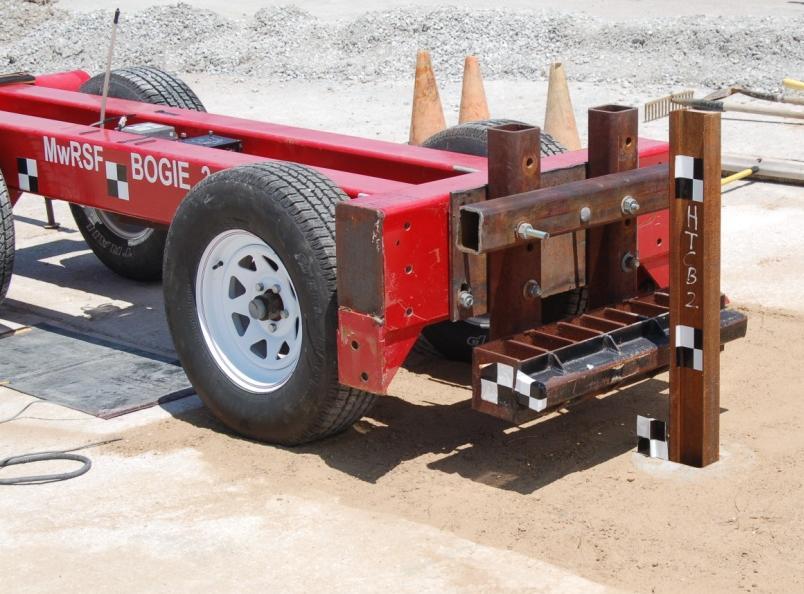
27 February, 212 Figure 3.8 Test Installation Setup 17
28 February, 212 Chapter 4 Component Test Conditions 4.1 Purpose Testing of the socketed foundations for cable guardrail posts was conducted in order to evaluate the structural integrity of the socketed foundations and to measure lateral deflections of the new, variable length, foundation designs placed in weak soil. 4.2 Scope Four bogie tests were conducted on S4x7.7 (S12x11.5) steel posts inserted into socketed foundations. The socketed foundations were placed in a sand pit satisfying the American Association of State Highway and Transportation Officials (AASHTO) A-3 sand material requirements. The target impact conditions were a speed of 2. mph (32.2 km/h) and an angle of degrees, or through the strong-axis of the post bending. All posts were impacted 11 in. (279 mm) above the groundline. A summary of the bogie testing is shown in table Test Facility Physical testing of the cable post base was conducted at the Midwest Roadside Safety Facility (MwRSF) outdoor proving grounds, which is located at the Lincoln Air Park on the northwest side of the Lincoln Municipal Airport. The facility is approximately 5 miles (8 km) northwest from the University of Nebraska-Lincoln s city campus. 4.4 Equipment and Instrumentation Equipment and instrumentation utilized to collect and record data during the dynamic bogie tests included a bogie, accelerometers, pressure tape switches, a string potentiometer, highspeed and standard-speed digital video cameras, and still camera. 18
29 19 February, 212 Table 4.1 Scope of Physical Testing Test No. HTCB-1 HTCB-2 HTCB-3 HTCB-4 Post Type S4x7.7 (S12x11.5) S4x7.7 (S12x11.5) S4x7.7 (S12x11.5) S4x7.7 (S12x11.5) Post Length in. (mm) 47 (1,194) 47 (1,194) 47 (1,194) 47 (1,194) Target Impact Velocity mph (km/h) 2 (32) 2 (32) 2 (32) 2 (32) Impact Orientation deg Strong Axis deg Strong Axis deg Strong Axis deg Strong Axis Embedment Depth in. (mm) 24 (61) 36 (914) 6 (1,524) 6 (1,524) Rebar Configuration A B B C
 square tube mounted on the outside flange of a W6x25 (W152x37.2) steel beam with reinforcing gussets.")
30 February, Bogie A rigid-frame bogie equipped with a variable height, detachable impact head was used to strike the posts. The bogie impact head consisted of a 2½-in. x 2½-in. x 5/16-in. (64-mm x 64- mm x 8-mm) square tube mounted on the outside flange of a W6x25 (W152x37.2) steel beam with reinforcing gussets. The impact head was bolted to the bogie vehicle, creating a rigid frame with an impact height of 11 in. (279 mm). The bogie and impact head are shown in figure 4.1. The weight of the bogie with the addition of the mountable impact head for test no. HTCB-1 was 1,84 lb (818 kg). After the first test, an additional steel section was used to attach the impact head to the bogie frame. Thus, the nominal bogie weight for test nos. HTCB-2 through HTCB-4 was 1,845 lb (837 kg). Approximate bogie weights are listed in their respective test description sections. Figure 4.1 Rigid Frame Bogie with Impact Head A pickup truck with a reverse cable tow system was used to propel the bogie to a target impact speed of 2 mph (32 km/h). When the bogie approached the end of the guidance system, it was released from the tow cable, allowing it to be free rolling when it impacted the post. A 2
31 February, 212 remote braking system was installed on the bogie allowing it to be brought safely to rest after the test Accelerometers Two accelerometer systems were mounted on the bogie vehicle near its center of gravity to measure the impact accelerations in the longitudinal, lateral, and vertical directions. However, only the longitudinal accelerations were processed and reported. The first accelerometer, Model EDR-3, was a triaxial, piezoresistive accelerometer system developed by Instrumented Sensor Technology (IST) of Okemos, Michigan. The EDR-3 was configured with 256 kb of RAM memory, a range of ±2 g s, a sample rate of 3,2 Hz, and a 1,12 Hz low-pass filter. The DynaMax 1 (DM-1) computer software program and a customized Microsoft Excel worksheet were used to analyze and plot the accelerometer data. A second triaxial piezoresistive accelerometer system, Model EDR-4 6DOF-5/12, was used. The EDR-4 6DOF-5/12, also developed by IST of Okemos, Michigan, includes three differential channels as well as three single-ended channels. The EDR-4 6DOF-5/12 was configured with 24 MB of RAM memory, a range of ±5 g s, a sample rate of 1, Hz, and a 1,677 Hz anti-aliasing filter. The EDR4COM and DynaMax Suite computer software programs and a customized Microsoft Excel worksheet were used to analyze and plot the accelerometer data Pressure Tape Switches Three pressure tape switches, spaced at approximately 18 in. (457 mm) intervals and placed near the end of the bogie track, were used to determine the speed of the bogie before the impact. As the right-front tire of the bogie passed over each tape switch, a strobe light was fired sending an electronic timing signal to the data acquisition system. The system recorded the signals and the time each occurred. The speed was then calculated using the spacing between the 21
32 February, 212 sensors and the time between the signals. Strobe lights and high-speed video analysis were used only as a backup in the event that vehicle speeds could not be determined from the electronic data Photography One AOS VITcam high-speed digital video camera and two JVC digital video cameras were used to document each test. The AOS high-speed camera had a frame rate of 5 frames per second and the JVC digital video cameras had frame rates of frames per second. All three cameras were placed laterally from the post, with a view perpendicular to the bogie s direction of travel. A Nikon D5 digital still camera was also used to document pre- and post-test conditions for all tests String Potentionmeters A linear displacement transducer, or string potentiometer, was installed on the front edge of the sand pit to determine the displacement of the post foundation for each bogie test. The positioning and setup of the string potentiometer are shown in figure 4.2. The string potentiometer used was a UniMeasure PA-5 with a range of 5 in. (1,27 mm). A Measurements Group Vishay Model 231 signal conditioning amplifier was used to condition and amplify the low-level signals to high-level outputs for multichannel, simultaneous dynamic recording in the LabVIEW software. The sample rate of the string potentiometers was 1, Hz End of Test Determination During standard bogie-post impact events, the desired test results have been based on force-deflection characteristics. Subsequently, the end of test has typically been defined as the first of three occurrences: (1) fracture of the test article; (2) excessive rotation of the test article; or (3) the bogie vehicle overriding or losing contact with the test article. However, the focus of 22

33 February, 212 the four bogie tests conducted herein was to evaluate the structural adequacy of the socketed foundations and to measure the maximum deflections or rotations of the foundations. Since the maximum resistive forces for the post assembly were restricted by the material and section properties of the post, the data recorded by the accelerometers would only be important in measuring the load at fracture. Therefore, the first two end of test criteria were discarded, and the true end of test was defined as the time when the bogie vehicle overrode or lost contact with the post assembly. Figure 4.2 Typical String Potentiometer Setup 4.5 Data Processing The electronic accelerometer data obtained in the dynamic testing was filtered using the SAE Class 6 Butterworth filter conforming to the SAE J211/1 specifications [8]. The pertinent 23
34 February, 212 acceleration signal was extracted from the bulk of the data signals. The processed acceleration data was then multiplied by the mass of the bogie to get the impact force using Newton s Second Law. Next, the acceleration trace was integrated to find the change in velocity versus time. Initial velocity of the bogie, calculated from the pressure tape switch data, was used to determine the bogie velocity throughout the impact event. The calculated velocity trace was then integrated to find the bogie s displacement. Combining the previous results, a force versus deflection curve was plotted for each test. These curves only illustrated the lateral resistive force applied at displacements equal to the movement of the bogie vehicle and impact head, not the displacement of the post or the socketed foundation. Finally, integration of the force versus deflection curve produced the energy versus displacement curve for each test. Historically, the EDR-3 unit has provided more accurate data than the EDR-4 unit. Therefore, the graphs and values presented are taken from the data provided by the EDR-3 accelerometer. However, data obtained from both the EDR-3 and EDR-4 units are shown in Appendix A. Similar to the accelerometer data, the pertinent data from the string potentiometer was extracted from the bulk signal. The extracted data signal was converted to a displacement using the transducers calibration factor. Displacement versus time plots were created to describe the motion of the foundation at groundline. The exact moment of impact could not be determined from the string potentiometer data as impact may have occurred a few milliseconds prior to foundation movement. Thus, the extracted time shown in the displacement versus time plots should not be taken as a precise time after impact, but rather a general time in relation to the impact event. 24
35 Chapter 5 Component Testing Results and Discussion February, Results The information desired from each component test was the performance of each socketed foundation in terms of both structural integrity and the displacement of the foundation in weak soils. Additionally, accelerometer data was used to find the resistance force supplied by the cable barrier post and foundation assembly. The displacements calculated from the acceleration data are related to the motion of the bogie, while the displacements calculated from the string potentiometer are related to the motion of the socketed foundation. Thus, these displacements are in reference to different components and were not expected to be similar. The total force on the post assembly included a vertical component as the post rotated past vertical. However, this vertical component was thought to be negligible when compared to the horizontal force at the beginning of the impact event. Therefore, only the longitudinal forces applied to the bogie (lateral forces on the post assembly) were analyzed and evaluated. Although the acceleration data was applied to the impact location, the data came from the center of gravity of the bogie. This added error to the data, since the bogie was not perfectly rigid and vibrations in the bogie were recorded. The bogie may have rotated during impact causing differences in accelerations between the bogie center of mass and the bogie impact head. Filtering procedures were applied to the data to smooth out vibrations, and rotations of the bogie during testing were minor. Thus, the data was still deemed appropriate and valid. One useful aspect of using accelerometer data was influences of inertia on the reaction force were included. This was important as the mass of the post, foundation, and soil would affect barrier performance and test results. 25
36 February, Test No. HTCB-1 Test no. HTCB-1 was conducted on June 16, 29 at approximately 2:45 p.m. The weather conditions as per the National Oceanic and Atmosphere Administration (station 14939/LNK) were reported and are shown in table 5.1. Table 5.1 Weather Conditions, Test No. HTCB-1 Temperature 82 F Humidity 53% Wind Speed mph Wind Direction NA Sky Conditions Sunny Visibility 1 Statute Miles Pavement Surface Dry Previous 3-Day Precipitation.29 in. Previous 7-Day Precipitation.74 in. The 1,84-lb (818-kg) bogie impacted the post and foundation assembly at a speed of 2.7 mph (33.3 km/h). The centerline of the bogie was aligned perpendicular to the strong-axis of the S4x7.7 (S12x11.5) steel post with the impact head centered on the front face of the post at an impact height of 11 in. (279 mm) above the groundline. Test results are described in the following section and sequential photographs are shown in Figure 5.1. Additional post-test photographs are shown in figure 5.2. Following impacts, the post and socketed foundation assembly rotated through the sand/soil. At.158 sec., the bogie overrode and lost contact with the post assembly. The post assembly rotated backward almost a full 9 degrees with the top of the post just above groundline. Both the steel post and the concrete foundation remained intact and undamaged. Time-sequential photographs are shown in figure 5.1. Component damage and post base deflection are shown in figure
37 February, 212 At the beginning of the impact event, inertial effects resulted in a peak force of 18.8 kips (83.6 kn) at 1.7 in. (43 mm) of deflection. After the initial spike, the force level remained around 5 kips (22 kips) until a deflection of 8 in. (23 mm). After 8 in (23 mm) of deflection, the post and foundation assembly provided minimal resistance; since, the socketed foundation was rotating through the soil, and the bogie vehicle overrode the post. The bogie traveled 49.3 in. (1,252 mm) before overriding and losing contact with the post. A total of 13.8 kip-in. (11.7 kj) of energy was absorbed by the post and foundation assembly during impact. Force versus deflection and energy versus deflection curves were created from the accelerometer data and are shown in Figure 5.3. According to the string potentiometer, the top of the socketed foundation reached a maximum dynamic and permanent set deflection of 19.8 in. (53 mm) and 19 in. (483 mm), respectively, as shown in Figure


38 February, 212. sec.114 sec.32 sec.2 sec.44 sec.476 sec Figure 5.1 Time-Sequential Photographs, Test No. HTCB-1 28

39 February, 212 Figure 5.2 System Damage, Test No. HTCB-1 29
40 February, Force (kips) Displacement (in.) HTCB Force Energy Energy (kip-in.) Displacement (in.) Figure 5.3 Force vs. Deflection and Energy vs. Deflection, Test No. HTCB-1 3 HTCB Time (sec) Figure 5.4 Deflection of the Socketed Foundation, Test No. HTCB-1 3
41 February, Test No. HTCB-2 Test no. HTCB-2 was conducted on June 17, 29 at approximately 1:15 p.m. The weather conditions as per the National Oceanic and Atmosphere Administration (station 14939/LNK) were reported and are shown in table 5.2. Table 5.2 Weather Conditions, Test No. HTCB-2 Temperature 93 F Humidity 36 % Wind Speed 11 mph Wind Direction 11 from True North Sky Conditions Sunny Visibility 1 Statute Miles Pavement Surface Dry Previous 3-Day Precipitation.29 in. Previous 7-Day Precipitation.7 in. The 1,845 lb (837 kg) bogie impacted the post and foundation assembly at a speed of 2.4 mph (32.8 km/h). The centerline of the bogie was aligned perpendicular to the strong-axis of the S4x7.7 (S12x11.5) steel post with the impact head centered on the front face of the post at an impact height of 11 in. (279 mm) above the groundline. Following impact, the post and socketed foundation assembly rotated through the sand/soil. At.194 seconds, the bogie overrode and lost contact with the post assembly. The post assembly rotated backward almost a full 9 degrees with the top of the post just above the groundline. The steel post remained undamaged throughout the test, while the concrete foundation received only minor cracking to the top surface downstream of the steel socket and the upstream side 13 in. (33 mm) from the top. The cracks on the upstream side correspond closely with the location of the bottom of the steel socket inside the foundation. Time-sequential 31
42 February, 212 photographs are shown in Figure 5.5. Component damage and post base deflection are shown in figures 6 and 6. At the beginning of the impact event, inertial effects resulted in a peak force of 24.2 kips (17.6 kn) at 1.8 in. (46 mm) of deflection. After the initial spike, the post and foundation assembly provided a relatively constant force level ranging from 3 to 5 kips (13 to 22 kn) until the bogie had traveled 25 in. (635 mm). Only minimal resistance was recorded through the remainder of the test. The bogie traveled 53.4 in. (1,356 mm) before overriding and losing contact with the post. A total of kip-in. (19.1 kj) of energy was absorbed by the post and foundation assembly during impact. Force versus deflection and energy versus deflection curves were created from the accelerometer data and are shown in Figure 5.8. According to the string potentiometer, the top of the socketed foundation reached a maximum dynamic and permanent set deflection of 27. in. (686 mm) and 25.5 in. (648 mm), respectively, as shown in Figure


43 February, 212. sec.9 sec.3 sec.12 sec.54 sec.568 sec Figure 5.5 Time-Sequential Photographs, Test No. HTCB-2 33

44 34 February, 212 Figure 5.6 System Damage, Test No. HTCB-2


45 February, 212 Figure 5.7 Concrete Damage, Test No. HTCB-2 35
46 February, Displacement (in.) HTCB Force (kips) Force Energy Energy (kip-in.) Displacement (in.) Figure 5.8 Force vs. Deflection and Energy vs. Deflection, Test No. HTCB-2 3 HTCB Time (sec) Figure 5.9 Deflections of the Socketed Foundation, Test No. HTCB-2 36
47 February, Test No. HTCB-3 Test no. HTCB-3 was conducted on June 25, 29 at approximately 9:45 a.m. The weather conditions as per the National Oceanic and Atmosphere Administration (station 14939/LNK) were reported and are shown in table 5.3. Table 2.3 Weather Conditions, Test No. HTCB-3 Temperature 83 F Humidity 65% Wind Speed mph Wind Direction NA Sky Conditions Sunny Visibility 1 Statute Miles Pavement Surface Dry Previous 3-Day Precipitation.83 in. Previous 7-Day Precipitation 2.48 in. The 1,844 lb (836 kg) bogie impacted the post and foundation assembly at a speed of 21.2 mph (34.1 km/h). The centerline of the bogie was aligned perpendicular to the strong-axis of the S4x7.7 (S12x11.5) steel post with the impact head centered on the front face of the post at an impact height of 11 in. (279 mm). Upon impact, the post and socketed foundation assembly began to deflect and rotate backward. At.12 seconds after impact, the concrete foundation began to fracture apart around the steel socket. By.4 seconds, chunks of concrete from the top of the foundation disengaged allowing the socket to rotate without confinement. At.148 seconds, the bogie overrode and lost contact with the post. By this time, the rebar serving as the attachment point for the string potentiometer wire had disengaged from the concrete foundation and was being pulled back toward the transducer. Time-sequential photographs are shown in Figure
48 February, 212 The post sustained only minor plastic deformation at a location coincident with the top of the steel socket. The top of the socketed foundation sustained severe damage as most of the concrete from the top 17 in. (432 mm) had fractured away. The top circumferential rebar loop was bent and both of the longitudinal bars on the upstream side were sheared off near the center of the socket. Post-test photographs documenting the damage sustained by the footing assembly are shown in figures 5.11 and At the beginning of the bogie test, inertial effects resulted in a peak force of 28. kips (124.6 kn) at 1.7 in. (43 mm) of deflection. Substantial resistance was only recorded over 7 in. (178 mm) of deflection. After this point, the concrete foundation had fractured and only small force resistances were present until the bogie overrode the post. According to the accelerometer data, a total of kip-in. (13.8 kj) of energy was absorbed during the impact event. Force versus deflection and energy versus deflection curves were created from accelerometer data and are shown in Figure The string potentiometer recorded a maximum deflection of 18.1 in. (46 mm) for the socketed foundation before the attachment point rebar disengaged, as shown in Figure. A true deflection could not be quantified due to the concrete foundation fracturing apart. 38

49 February, 212. sec.94 sec.14 sec.146 sec.4 sec.472 sec Figure 5.1 Time-Sequential Photographs, Test No. HTCB-3 39


50 February, 212 Figure 5.11 System Damage, Test No. HTCB-3 4


51 February, 212 Figure 5.12 System Damage, Test No. HTCB-3 41
52 February, Displacement (in.) HTCB Force (kips) Force Energy Energy (kip-in.) Displacement (in.) Figure 5.13 Force vs. Deflection and Energy vs. Deflection, Test No. HTCB-3 3 HTCB Time (sec) Figure 5.14 Deflection of the Socketed Foundation, Test No. HTCB-3 42
53 February, Test No. HTCB 4 Test no. HTCB-4 was conducted on September 23, 29 at approximately 1:45 a.m. The weather conditions as per the National Oceanic and Atmosphere Administration (station 14939/LNK) were reported and are shown in Table 5.4. Table 5.4 Weather Conditions, Test No. HTCB-4 Temperature 63 F Humidity 65% Wind Speed mph Wind Direction NA Sky Conditions Sunny Visibility 1 Statute Miles Pavement Surface Dry Previous 3-Day Precipitation.27 in. Previous 7-Day Precipitation.27 in. The 1,839-lb (834-kg) bogie impacted the post and foundation assembly at a speed of 19.6 mph (31.6 km/h). The centerline of the bogie was aligned perpendicular to the strong-axis of the S4x7.7 (S12x11.5) steel post with the impact head centered on the front face of the post at an impact height of 11 in. (279 mm) above the groundline. Upon impact, the post and socketed foundation assembly began to rotate backward through the sand/soil. By.15 seconds after impact, large chunks of concrete had fractured from the socketed foundation. The exact time of fracture could not be determined from the highspeed video due to the displaced debris blocking the view. At.2 seconds, the bogie overrode and lost contact with the post. Time-sequential photographs are shown in Figure The post sustained no significant damage during the bogie test; however, the concrete foundation was severely damaged. The top 16 in. (46 mm) of concrete on the post base 43
54 February, 212 fractured and disengaged, exposing the socket and upper rebar in the assembly. Significant transverse cracking was found lower on the foundation. The steel socket tube rotated backward and the top three pieces of circumferential rebar were exposed. The top two circumferential rebar pieces were bent and deformed. All four of the vertical bars were bent and the vertical rebar on the upstream side fractured near the bottom of the socket. During excavation of the socketed foundation, an air pocket approximately 1 in. (25 mm) in depth was found along the front side of the assembly that may have contributed to the failure in the base. Component damage is shown in figures 5.16 and At the beginning of the bogie test, inertial effects resulted in a peak force of 23.5 kips (14.5 kn) at 1.6 in. (41 mm) of deflection. After this peak, the force steadily decreased until it fell below 5 kips (22 kn) at a deflection of 14 in. (356 mm). Only minor resistance forces were recorded after this point as the bogie overrode the post. According to the accelerometer data, a total of kip-in. (19.9 kj) of energy was absorbed during the impact event. Force versus deflection and energy versus deflection curves were created from accelerometer data and are shown in Figure The string potentiometer was not used in this test due to concerns of damaging it after the foundation in test no. HTCB-3 fractured. Similar to test no. HTCB-3, a final deflection of the socketed foundation could not be determined due to the concrete foundation fracturing apart. 44


55 February, 212. sec.114 sec.38 sec.224 sec.64 sec.3 sec Figure 5.15 Time-Sequential Photographs, Test No. HTCB-4 45


56 February, 212 Figure 5.16 System Damage, Test No. HTCB-4 46


57 February, 212 Figure 5.17 System Damage, Test No. HTCB-4 47
Cable-to-Post Attachments for Use in Non- Proprietary High-Tension Cable Median Barrier Phase II
 University of Nebraska - Lincoln DigitalCommons@University of Nebraska - Lincoln Nebraska Department of Transportation Research Reports Nebraska LTAP 3-24-2016 Cable-to-Post Attachments for Use in Non-
TEST MATRICES FOR EVALUATING CABLE MEDIAN BARRIERS PLACED IN V-DITCHES
 Midwest States Regional Pooled Fund Research Program Fiscal Year 2012 (Year 22) Research Project Number TPF-5(193) Supplement #44 NDOR Sponsoring Agency Code RPFP-12-CABLE1&2 TEST MATRICES FOR EVALUATING
Midwest Guardrail System Without Blockouts
 Duplication for publication or sale is strictly prohibited without prior written permission of the Transportation Research Board Paper No. 13-0418 Midwest Guardrail System Without Blockouts by John D.
PERFORMANCE EVALUATION OF THE PERMANENT NEW JERSEY SAFETY SHAPE BARRIER UPDATE TO NCHRP 350 TEST NO (2214NJ-2)
") PERFORMANCE EVALUATION OF THE PERMANENT NEW JERSEY SAFETY SHAPE BARRIER UPDATE TO NCHRP 350 TEST NO. 4-12 (2214NJ-2) Submitted by Karla A. Polivka, M.S.M.E., E.I.T. Research Associate Engineer Dean L.
PERFORMANCE EVALUATION OF THE PERMANENT NEW JERSEY SAFETY SHAPE BARRIER UPDATE TO NCHRP 350 TEST NO. 4-12 (2214NJ-2) Submitted by Karla A. Polivka, M.S.M.E., E.I.T. Research Associate Engineer Dean L.
Manual for Assessing Safety Hardware
 American Association of State Highway and Transportation Officials Manual for Assessing Safety Hardware 2009 vii PREFACE Effective traffic barrier systems, end treatments, crash cushions, breakaway devices,
DEFLECTION LIMITS FOR TEMPORARY CONCRETE BARRIERS
 Midwest State s Regional Pooled Fund Research Program Fiscal Year 1998-1999 (Year 9) NDOR Research Project Number SPR-3(017) DEFLECTION LIMITS FOR TEMPORARY CONCRETE BARRIERS Submitted by Dean L. Sicking,
Development of a TL-5 Vertical Faced Concrete Median Barrier Incorporating Head Ejection Criteria
 Midwest States Regional Pooled Fund Research Program Fiscal Year 2004-2005 (Year 15) Research Project Number SPR-3(017) NDOR Sponsoring Agency Code RPFP-05-01 Development of a TL-5 Vertical Faced Median
INCREASED SPAN LENGTH FOR THE MGS LONG-SPAN GUARDRAIL SYSTEM PART III: FAILURE ANALYSIS
 Midwest States Pooled Fund Research Program Fiscal Years 2013 (Years 23) Research Project Number TPF-5(193) Supplement #56 NDOR Sponsoring Agency Code RPFP-13-MGS-3 INCREASED SPAN LENGTH FOR THE MGS LONG-SPAN
CRITICAL FLARE RATES FOR W-BEAM GUARDRAIL DETERMINING MAXIMUM CAPACITY USING COMPUTER SIMULATION NCHRP 17-20(3)
") CRITICAL FLARE RATES FOR W-BEAM GUARDRAIL DETERMINING MAXIMUM CAPACITY USING COMPUTER SIMULATION NCHRP 17-2(3) Submitted by Beau D. Kuipers, B.S.M.E., E.I.T. Graduate Research Assistant Ronald K. Faller,
CRITICAL FLARE RATES FOR W-BEAM GUARDRAIL DETERMINING MAXIMUM CAPACITY USING COMPUTER SIMULATION NCHRP 17-2(3) Submitted by Beau D. Kuipers, B.S.M.E., E.I.T. Graduate Research Assistant Ronald K. Faller,
Continued Development of a Non-Proprietary, High-Tension, Cable End Terminal System
 University of Nebraska - Lincoln DigitalCommons@University of Nebraska - Lincoln Nebraska Department of Transportation Research Reports Nebraska LTAP 4-29-2016 Continued Development of a Non-Proprietary,
PERFORMANCE EVALUATION OF THE MODIFIED G4(1S) GUARDRAIL UPDATE TO NCHRP 350 TEST NO WITH 28" C.G. HEIGHT (2214WB-2)
 GUARDRAIL UPDATE TO NCHRP 350 TEST NO WITH 28 C.G. HEIGHT (2214WB-2)") PERFORMANCE EVALUATION OF THE MODIFIED G4(1S) GUARDRAIL UPDATE TO NCHRP 350 TEST NO. 3-11 WITH 28" C.G. HEIGHT (2214WB-2) Submitted by Karla A. Polivka, M.S.M.E., E.I.T. Research Associate Engineer Dean
PERFORMANCE EVALUATION OF THE MODIFIED G4(1S) GUARDRAIL UPDATE TO NCHRP 350 TEST NO. 3-11 WITH 28" C.G. HEIGHT (2214WB-2) Submitted by Karla A. Polivka, M.S.M.E., E.I.T. Research Associate Engineer Dean
Development and Implementation of the Simplified MGS Stiffness Transition
 Duplication for publication or sale is strictly prohibited without prior written permission of the Transportation Research Board Paper No. 12-3367 Development and Implementation of the Simplified MGS Stiffness
REPORT NO. TR-P NC SAFETY COMPLIANCE TESTING FOR FMVSS 223 REAR IMPACT GUARDS 2007 TRANSFREIGHT TECHNOLOGY NHTSA NO.
 REPORT NO. SAFETY COMPLIANCE TESTING FOR FMVSS 223 REAR IMPACT GUARDS 2007 TRANSFREIGHT TECHNOLOGY NHTSA NO. RIG 009 PREPARED BY: KARCO ENGINEERING, LLC. 9270 HOLLY ROAD ADELANTO, CALIFORNIA 92301 SEPTEMBER
EXTENDING TL-2 SHORT-RADIUS GUARDRAIL TO LARGER RADII
 Research Project Number TPF-5(193) Supplement 27 EXTENDING TL-2 SHORT-RADIUS GUARDRAIL TO LARGER RADII Submitted by Cody S. Stolle, Ph.D., E.I.T. Post-Doctoral Research Associate Robert W. Bielenberg,
PERFORMANCE EVALUATION OF THE FREE-STANDING TEMPORARY BARRIER UPDATE TO NCHRP 350 TEST NO (2214TB-1)
") PERFORMANCE EVALUATION OF THE FREE-STANDING TEMPORARY BARRIER UPDATE TO NCHRP 350 TEST NO. 3-11 (2214TB-1) Submitted by Karla A. Polivka, M.S.M.E., E.I.T. Research Associate Engineer Dean L. Sicking, Ph.D.,
PERFORMANCE EVALUATION OF THE FREE-STANDING TEMPORARY BARRIER UPDATE TO NCHRP 350 TEST NO. 3-11 (2214TB-1) Submitted by Karla A. Polivka, M.S.M.E., E.I.T. Research Associate Engineer Dean L. Sicking, Ph.D.,
PERFORMANCE EVALUATION OF THE FREE-STANDING TEMPORARY BARRIER UPDATE TO NCHRP 350 TEST NO WITH 28" C.G. HEIGHT (2214TB-2)
") PERFORMANCE EVALUATION OF THE FREE-STANDING TEMPORARY BARRIER UPDATE TO NCHRP 350 TEST NO. 3-11 WITH 28" C.G. HEIGHT (2214TB-2) Submitted by Karla A. Polivka, M.S.M.E., E.I.T. Research Associate Engineer
PERFORMANCE EVALUATION OF THE FREE-STANDING TEMPORARY BARRIER UPDATE TO NCHRP 350 TEST NO. 3-11 WITH 28" C.G. HEIGHT (2214TB-2) Submitted by Karla A. Polivka, M.S.M.E., E.I.T. Research Associate Engineer
PR V2. Submitted by. Professor MIDWEST Vine Street (402) Submitted to
 Submitted to") FINAL REPORT PR4893118-V2 ZONE OF INTRUSION STUDY Submitted by John D. Reid, Ph.D. Professor Dean L.. Sicking, Ph.D., P.E. Professorr and MwRSF Director MIDWEST ROADSIDE SAFETY FACILITY University of Nebraska-Lincoln
FINAL REPORT PR4893118-V2 ZONE OF INTRUSION STUDY Submitted by John D. Reid, Ph.D. Professor Dean L.. Sicking, Ph.D., P.E. Professorr and MwRSF Director MIDWEST ROADSIDE SAFETY FACILITY University of Nebraska-Lincoln
DEVELOPMENT OF A TRANSITION BETWEEN FREE-STANDING AND REDUCED-DEFLECTION PORTABLE CONCRETE BARRIERS PHASE I
 Research Project Number TPF-5(193) Supplement #78 DEVELOPMENT OF A TRANSITION BETWEEN FREE-STANDING AND REDUCED-DEFLECTION PORTABLE CONCRETE BARRIERS PHASE I Submitted by Mojdeh Asadollahi Pajouh, Ph.D.
Evaluation of the Midwest Guardrail System Stiffness Transition with Curb
 Duplication for publication or sale is strictly prohibited without prior written permission of the Transportation Research Board Paper No. -0 Evaluation of the Midwest Guardrail System Stiffness Transition
1962: HRCS Circular 482 one-page document, specified vehicle mass, impact speed, and approach angle for crash tests.
 1 2 3 1962: HRCS Circular 482 one-page document, specified vehicle mass, impact speed, and approach angle for crash tests. 1973: NCHRP Report 153 16-page document, based on technical input from 70+ individuals
SGR52 TOP-MOUNTED WEAK-POST GUARDRAIL ATTACHED TO CULVERT PLAN VIEW ELEVATION VIEW DETAIL B DETAIL A SHEET NO. DATE: 37 1/2" 953 (TYP) 150" 3810
 150 3810") PLAN VIEW C 150" 3810 37 1/2" 953 (TYP) A B C 8-FBB01 RWB01a FWR01 RWM04a FWR01 RWB01a RWM04a PSF01 FBX08a PSF01 FBX08a DETAIL A DETAIL B 1 of 7 12/5/2016 INTENDED USE The Top-Mounted Weak-Post Guardrail
PLAN VIEW C 150" 3810 37 1/2" 953 (TYP) A B C 8-FBB01 RWB01a FWR01 RWM04a FWR01 RWB01a RWM04a PSF01 FBX08a PSF01 FBX08a DETAIL A DETAIL B 1 of 7 12/5/2016 INTENDED USE The Top-Mounted Weak-Post Guardrail
MINIMUM EFFECTIVE LENGTH FOR THE MIDWEST GUARDRAIL SYSTEM
 Duplication for publication or sale is strictly prohibited without prior written permission of the Transportation Research Board Paper No. 15-0484 MINIMUM EFFECTIVE LENGTH FOR THE MIDWEST GUARDRAIL SYSTEM
Evaluation of the Midwest Guardrail System stiffness transition with curb
 University of Nebraska - Lincoln DigitalCommons@University of Nebraska - Lincoln Civil Engineering Faculty Publications Civil Engineering 2016 Evaluation of the Midwest Guardrail System stiffness transition
CRASH TEST REPORT FOR PERIMETER BARRIERS AND GATES TESTED TO SD-STD-02.01, REVISION A, MARCH Anti-Ram Bollards
 CRASH TEST REPORT FOR PERIMETER BARRIERS AND GATES TESTED TO SD-STD-02.01, REVISION A, MARCH 2003 Anti-Ram Bollards Prepared for: RSA Protective Technologies, LLC 1573 Mimosa Court Upland, CA 91784 Test
SAFETY PERFORMANCE OF WORK-ZONE DEVICES UNDER MASH TESTING
 SAFETY PERFORMANCE OF WORK-ZONE DEVICES UNDER MASH TESTING Schmidt, Faller, Lechtenberg, Sicking, Holloway Midwest Roadside Safety Facility Nebraska Transportation Center University of Nebraska-Lincoln
CRASH TEST REPORT FOR PERIMETER BARRIERS AND GATES TESTED TO SD-STD-02.01, REVISION A, MARCH Anti-Ram Bollards
 CRASH TEST REPORT FOR PERIMETER BARRIERS AND GATES TESTED TO SD-STD-02.01, REVISION A, MARCH 2003 Anti-Ram Bollards Prepared for: RSA Protective Technologies, LLC 1573 Mimosa Court Upland, CA 91784 Test
Research Project Number SPR-P1(13)M326 DEVELOPMENT OF A MASH TL-3 TRANSITION BETWEEN GUARDRAIL AND PORTABLE CONCRETE BARRIERS.
M326 DEVELOPMENT OF A MASH TL-3 TRANSITION BETWEEN GUARDRAIL AND PORTABLE CONCRETE BARRIERS.") Research Project Number SPR-P1(13)M326 DEVELOPMENT OF A MASH TL-3 TRANSITION BETWEEN GUARDRAIL AND PORTABLE CONCRETE BARRIERS Submitted by David A. Gutierrez, B.S.C.E., E.I.T. Graduate Research Assistant
Research Project Number SPR-P1(13)M326 DEVELOPMENT OF A MASH TL-3 TRANSITION BETWEEN GUARDRAIL AND PORTABLE CONCRETE BARRIERS Submitted by David A. Gutierrez, B.S.C.E., E.I.T. Graduate Research Assistant
AASHTO Manual for Assessing Safety Hardware, AASHTO/FHWA Joint Implementation Plan Standing Committee on Highways September 24, 2015
 AASHTO Manual for Assessing Safety Hardware, 2015 AASHTO/FHWA Joint Implementation Plan Standing Committee on Highways September 24, 2015 Full Scale MASH Crash Tests (NCHRP 22-14(02)) Conducted several
DEVELOPMENT OF A MASH TL-3 TRANSITION BETWEEN GUARDRAIL AND PORTABLE CONCRETE BARRIERS
 Duplication for publication or sale is strictly prohibited without prior written permission of the Transportation Research Board Paper No. 17-01712 DEVELOPMENT OF A MASH TL-3 TRANSITION BETWEEN GUARDRAIL
Crash Testing Growth Common Roadside Hardware Systems Draft FHWA and AASHTO Requirements for Implementing MASH 2015
 64 th Annual Illinois Traffic Safety and Engineering Conference October 14, 2015 Crash Testing Growth Common Roadside Hardware Systems Draft FHWA and AASHTO Requirements for Implementing MASH 2015 1 https://www.youtube.com/watch?feature
FAAC International, Inc.
 TEST REPORT FOR: FAAC International, Inc. J 355 HA M30 (K4) Bollard TESTED TO: ASTM F 2656-07 Standard Test Method for Vehicle Crash Testing of Perimeter Barriers Test M30 PREPARED FOR: FAAC International,
Heating Comparison of Radial and Bias-Ply Tires on a B-727 Aircraft
 'S Heating Comparison of Radial and Bias-Ply Tires on a B-727 Aircraft November 1997 DOT/FAA/AR-TN97/50 This document is available to the U.S. public through the National Technical Information Service
Development and Validation of a Finite Element Model of an Energy-absorbing Guardrail End Terminal
 Development and Validation of a Finite Element Model of an Energy-absorbing Guardrail End Terminal Yunzhu Meng 1, Costin Untaroiu 1 1 Department of Biomedical Engineering and Virginia Tech, Blacksburg,
ROBUST PROJECT Norwegian Public Roads Administration / Force Technology Norway AS
 ROBUST PROJECT Norwegian Public Roads Administration / Force Technology Norway AS Evaluation of small car - RM_R1 - prepared by Politecnico di Milano Volume 1 of 1 January 2006 Doc. No.: ROBUST-5-002/TR-2004-0039
Control of Pavement Smoothness in Kansas
 Report No. FHWA-KS-8-5 Final REPORT Control of Pavement Smoothness in Kansas William H. Parcells, Jr., P.E. Kansas Department of Transportation Topeka, Kansas May 29 KANSAS DEPARTMENT OF TRANSPORTATION
FHWA/IN/JTRP-2000/23. Final Report. Sedat Gulen John Nagle John Weaver Victor Gallivan
 FHWA/IN/JTRP-2000/23 Final Report DETERMINATION OF PRACTICAL ESALS PER TRUCK VALUES ON INDIANA ROADS Sedat Gulen John Nagle John Weaver Victor Gallivan December 2000 Final Report FHWA/IN/JTRP-2000/23 DETERMINATION
FAA T53-L-13L Turbine Fragment Containment Test
 DOT/FAA/AR-98/22 Office of Aviation Research Washington, D.C. 20591 FAA T53-L-13L Turbine Fragment Containment Test Appro- June 1998 Final Report This document is available to the U.S. public through the
Form DOT F (8-72) Texas Transportation Institute The Texas A&M University System College Station, Texas
 Texas Transportation Institute The Texas A&M University System College Station, Texas") 1. Report No. FHWA/TX-02/4162-1 Technical Report Documentation Page 2. Government Accession No. 3. Recipient's Catalog No. 4. Title and Subtitle EVALUATION OF TEXAS GRID-SLOT PORTABLE CONCRETE BARRIER
1. Report No. FHWA/TX-02/4162-1 Technical Report Documentation Page 2. Government Accession No. 3. Recipient's Catalog No. 4. Title and Subtitle EVALUATION OF TEXAS GRID-SLOT PORTABLE CONCRETE BARRIER
July 17, In Reply Refer To: HSSD/B-176A
 July 17, 2008 1200 New Jersey Avenue, SE. Washington, DC 20590 In Reply Refer To: HSSD/B-176A Mr. John Addy Hill & Smith Springvale Business and Industrial Park Bliston, Wolverhampton, West Midlands, UK,
Evaluation and Design of ODOT s Type 5 Guardrail with Tubular Backup
 Evaluation and Design of ODOT s Type 5 Guardrail with Tubular Backup Draft Final Report Chuck A. Plaxico, Ph.D. James C. Kennedy, Jr., Ph.D. Charles R. Miele, P.E. for the Ohio Department of Transportation
CRASH TESTING OF RSA/K&C ANTI-RAM FOUNDATION BOLLARD PAD IN ACCORDANCE WITH U.S. DEPARTMENT OF STATE DIPLOMATIC SECURITY SD-STD-02.
 CRASH TESTING OF RSA/K&C ANTI-RAM FOUNDATION BOLLARD PAD IN ACCORDANCE WITH U.S. DEPARTMENT OF STATE DIPLOMATIC SECURITY SD-STD-02.01 REVISION A Prepared for RSA Protective Technologies, LLC FINAL REPORT
July 10, Refer to: HSA-10/CC-78A
 July 10, 2003 Refer to: HSA-10/CC-78A Barry D. Stephens, P.E. Senior Vice President of Engineering ENERGY ABSORPTION Systems, Inc. 3617 Cincinnati Avenue Rocklin, California 95765 Dear Mr. Stephens: Your
Virginia Department of Transportation
 TEST REPORT FOR: Virginia Department of Transportation SKT SP 350 50 (15.24 m) System PREPARED FOR: Virginia Department of Transportation 1401 E. Broad St. Richmond, VA 23219 TEST REPORT NUMBER: REPORT
February 8, In Reply Refer To: HSSD/CC-104
 February 8, 2008 200 New Jersey Avenue, SE. Washington, DC 20590 In Reply Refer To: HSSD/CC-04 Barry D. Stephens, P.E. Sr. Vice President Engineering Energy Absorption Systems, Inc. 367 Cincinnati Avenue
NTC. Cable Median Barrier Failure Analysis and Prevention
 Nebraska Transportation Center Report # TRP-03-275-12 Final Report 25-1121-0001-428 Cable Median Barrier Failure Analysis and Prevention Dean L. Sicking, Ph.D., P.E. Professor Department of Civil Engineering
REPORT NUMBER: 301-CAL SAFETY COMPLIANCE TESTING FOR FMVSS 301 FUEL SYSTEM INTEGRITY HONDA MOTOR COMPANY 2007 HONDA ACCORD 4-DOOR SEDAN
 REPORT NUMBER: 301-CAL-07-05 SAFETY COMPLIANCE TESTING FOR FMVSS 301 FUEL SYSTEM INTEGRITY HONDA MOTOR COMPANY 2007 HONDA ACCORD 4-DOOR SEDAN NHTSA NUMBER: C75304 CALSPAN TEST NUMBER: 8832-F301-05 CALSPAN
June 27, In Reply Refer To: HSSD/B-176
 June 27, 2008 1200 New Jersey Avenue, SE. Washington, DC 20590 In Reply Refer To: HSSD/B-176 Mr. John Addy Hill & Smith Springvale Business and Industrial Park Bliston, Wolverhampton, West Midlands, UK,
June 5, In Reply Refer To: HSSD/B-178. Mr. Kevin K. Groeneweg Mobile Barriers LLC Genesee Trail Road Golden, CO Dear Mr.
 June 5, 2008 1200 New Jersey Avenue, SE. Washington, DC 20590 In Reply Refer To: HSSD/B-178 Mr. Kevin K. Groeneweg Mobile Barriers LLC 24918 Genesee Trail Road Golden, CO 80401 Dear Mr. Groeneweg: This
Remote Combination Adaptive Driving Equipment Investigation Dynamic Science, Inc. (DSI), Case Number G 1990 Ford Bronco Arizona October
, Case Number G 1990 Ford Bronco Arizona October") Remote Combination Adaptive Driving Equipment Investigation Dynamic Science, Inc. (DSI), Case Number 2007-76-131G 1990 Ford Bronco Arizona October 2007 This document is disseminated under the sponsorship
Remote Combination Adaptive Driving Equipment Investigation Dynamic Science, Inc. (DSI), Case Number 2007-76-131G 1990 Ford Bronco Arizona October 2007 This document is disseminated under the sponsorship
Development of Turning Templates for Various Design Vehicles
 Transportation Kentucky Transportation Center Research Report University of Kentucky Year 1991 Development of Turning Templates for Various Design Vehicles Kenneth R. Agent Jerry G. Pigman University of
SAFETY COMPLIANCE TESTING FOR FMVSS NO. 214S SIDE IMPACT PROTECTION (STATIC)
") REPORT NUMBER 214-GTL-09-002 SAFETY COMPLIANCE TESTING FOR S SIDE IMPACT PROTECTION (STATIC) MAZDA MOTOR CORPORATION 2009 MAZDA 3, PASSENGER CAR NHTSA NO. C95400 GENERAL TESTING LABORATORIES, INC. 1623
REPORT NUMBER 214-GTL-09-002 SAFETY COMPLIANCE TESTING FOR S SIDE IMPACT PROTECTION (STATIC) MAZDA MOTOR CORPORATION 2009 MAZDA 3, PASSENGER CAR NHTSA NO. C95400 GENERAL TESTING LABORATORIES, INC. 1623
TEST REPORT. Rendered to: HOMELAND VINYL PRODUCTS, INC. For: PVC Guardrail System Utilizing New Nylon/PVC Rail Mounting Bracket
 TEST REPORT Rendered to: HOMELAND VINYL PRODUCTS, INC. For: PVC Guardrail System Utilizing New Nylon/PVC Rail Mounting Bracket Report No: Report Date: 10/31/12 130 Derry Court York, PA 17406-8405 phone:
SUMMARY CHANGES FOR NCHRP REPORT 350 GUIDELINES [NCHRP (02)] Keith A. Cota, Chairman Technical Committee on Roadside Safety June 14, 2007
![SUMMARY CHANGES FOR NCHRP REPORT 350 GUIDELINES [NCHRP (02)] Keith A. Cota, Chairman Technical Committee on Roadside Safety June 14, 2007](/thumbs/87/97351925.jpg "SUMMARY CHANGES FOR NCHRP REPORT 350 GUIDELINES [NCHRP (02)] Keith A. Cota, Chairman Technical Committee on Roadside Safety June 14, 2007") SUMMARY CHANGES FOR NCHRP REPORT 350 GUIDELINES [NCHRP 22-14 (02)] Keith A. Cota, Chairman Technical Committee on Roadside Safety June 14, 2007 BACKGROUND Circular 482 (1962) First full scale crash test
SUMMARY CHANGES FOR NCHRP REPORT 350 GUIDELINES [NCHRP 22-14 (02)] Keith A. Cota, Chairman Technical Committee on Roadside Safety June 14, 2007 BACKGROUND Circular 482 (1962) First full scale crash test
Advances in Simulating Corrugated Beam Barriers under Vehicular Impact
 13 th International LS-DYNA Users Conference Session: Automotive Advances in Simulating Corrugated Beam Barriers under Vehicular Impact Akram Abu-Odeh Texas A&M Transportation Institute Abstract W-beam
TEXAS TRANSPORTATION INSTITUTE THE TEXAS A & M UNIVERSITY SYSTEM COLLEGE STATION, TEXAS 77843
 NCHRP REPORT 350 ASSESSMENT OF EXISTING ROADSIDE SAFETY HARDWARE by C. Eugene Buth, P.E. Senior Research Engineer Wanda L. Menges Associate Research Specialist and Sandra K. Schoeneman Research Associate
Florida s Turnpike Enterprise High Tension Median Cable Barrier Pilot Project. William H. Cook, P.E. Florida s Turnpike Assistant Roadway Engineer
 Florida s Turnpike Enterprise High Tension Median Cable Barrier Pilot Project William H. Cook, P.E. Florida s Turnpike Assistant Roadway Engineer Florida Turnpike Enterprise Miami (MP 0) to Wildwood (MP
PRODUCT DESCRIPTION. X-Tension DS. is suitable for all road types: Motorways, country roads, city streets for speed categories up to 110 km/h.
 INDEX Introduction 2 Product Description 3 Installation 6 Specifications 7 Crash Tests Table 8 Reusability 9 FAQ 10 Annexes 14 Drawings 15 Pictures 16 Crash Tests Results 18 Approvals 23 INTRODUCTION Improving
SAFETY COMPLIANCE TESTING FOR FMVSS NO. 103 WINDSHIELD DEFROSTING AND DEFOGGING SYSTEMS
 REPORT NUMBER 103-GTL-09-005 SAFETY COMPLIANCE TESTING FOR FMVSS NO. 103 WINDSHIELD DEFROSTING AND DEFOGGING SYSTEMS TOYOTA MOTOR CORPORATION 2009 LEXUS ES 350, PASSENGER CAR NHTSA NO. C95104 GENERAL TESTING
CRASH TEST OF MILE POST MARKER. T. J. Hirsch Research Engineer. and. Eugene Buth Assistant Research Engineer. Research Report Number 146-8
 CRASH TEST OF MILE POST MARKER by T. J. Hirsch Research Engineer and Eugene Buth Assistant Research Engineer Research Report Number 146-8 Studies of Field Adaption of Impact Attenuation Systems Research
SAFETY COMPLIANCE TESTING FOR FMVSS NO. 103 WINDSHIELD DEFROSTING AND DEFOGGING SYSTEMS
 REPORT NUMBER 103-GTL-07-001 SAFETY COMPLIANCE TESTING FOR FMVSS NO. 103 WINDSHIELD DEFROSTING AND DEFOGGING SYSTEMS HYUNDAI MOTOR COMPANY 2007 HYUNDAI ELANTRA, PASSENGER CAR NHTSA NO. C70502 GENERAL TESTING
SAFETY COMPLIANCE TESTING FOR FMVSS NO. 103 WINDSHIELD DEFROSTING AND DEFOGGING SYSTEMS
 REPORT NUMBER 103-GTL-11-002 SAFETY COMPLIANCE TESTING FOR WINDSHIELD DEFROSTING AND DEFOGGING SYSTEMS NISSAN MOTOR CO., LTD. 2011 NISSAN LEAF, PASSENGER CAR NHTSA NO. CB5200 GENERAL TESTING LABORATORIES,
D-25 Speed Advisory System
 Report Title Report Date: 2002 D-25 Speed Advisory System Principle Investigator Name Pesti, Geza Affiliation Texas Transportation Institute Address CE/TTI, Room 405-H 3135 TAMU College Station, TX 77843-3135
WP5 - Computational Mechanics B5 - Temporary Vertical Concrete Safety Barrier MAIN REPORT Volume 1 of 1
 ROBUST PROJECT TRL Limited WP5 - Computational Mechanics B5 - Temporary Vertical Concrete Safety Barrier MAIN REPORT Volume 1 of 1 December 2005 Doc. No.: ROBUST-5-010c Rev. 0. (Logo here) Main Report
KENTUCKY TRANSPORTATION CENTER
 Research Report KTC-08-10/UI56-07-1F KENTUCKY TRANSPORTATION CENTER EVALUATION OF 70 MPH SPEED LIMIT IN KENTUCKY OUR MISSION We provide services to the transportation community through research, technology
VULCAN BARRIER TL-3 GENERAL SPECIFICATIONS
 VULCAN BARRIER TL-3 GENERAL SPECIFICATIONS I. GENERAL A. The VULCAN BARRIER TL-3 (VULCAN TL-3) shall be a highly portable and crashworthy longitudinal barrier especially suited for use as a temporary barrier
MASH TEST 3-10 ON 31-INCH W-BEAM GUARDRAIL WITH STANDARD OFFSET BLOCKS
 TTI: 9-1002 MASH TEST 3-10 ON 31-INCH W-BEAM GUARDRAIL WITH STANDARD OFFSET BLOCKS ISO 17025 Laboratory Testing Certificate # 2821.01 Crash testing performed at: TTI Proving Ground 3100 SH 47, Building
Update to NCHRP Report 350. Current Safety Issues
 Workshop on the Update to NCHRP Report 350 and Current Safety Issues July 18 21, 2004 Sponsored by TRB COMMITTEE AFB20 ROADSIDE SAFETY DESIGN DoubleTree Hotel Overland Park-Corporate Woods 10100 College
CFIRE December 2009
 i BRIDGE ANALYSIS AND EVALUATION OF EFFECTS UNDER OVERLOAD VEHICLES (PHASE 1) CFIRE 02-03 December 2009 National Center for Freight & Infrastructure Research & Education College of Engineering Department
DISTRIBUTION: Electronic Recipients List TRANSMITTAL LETTER NO. (15-01) MINNESOTA DEPARTMENT OF TRANSPORTATION. MANUAL: Road Design English Manual
 MINNESOTA DEPARTMENT OF TRANSPORTATION. MANUAL: Road Design English Manual") DISTRIBUTION: Electronic Recipients List MINNESOTA DEPARTMENT OF TRANSPORTATION DEVELOPED BY: Design Standards Unit ISSUED BY: Office of Project Management and Technical Support TRANSMITTAL LETTER NO.
DISTRIBUTION: Electronic Recipients List MINNESOTA DEPARTMENT OF TRANSPORTATION DEVELOPED BY: Design Standards Unit ISSUED BY: Office of Project Management and Technical Support TRANSMITTAL LETTER NO.
Guardrail/Bridgerail Recommendations for Very Low Volume Local Roads in Kansas
 Guardrail/Bridgerail Recommendations for Very Low Volume Local Roads in Kansas MINK Conference September 20, 2017 Ronald J. Seitz, P.E. and Tod Salfrank The Problem The Local Road System in Kansas is Very
ASTM F TEST M30 ON THE RSS-3000 DROP BEAM SYSTEM
 Proving Ground Test Report No.: 510602-RSS3 Test Report Date: January 2014 ASTM F2656-07 TEST M30 ON THE RSS-3000 DROP BEAM SYSTEM by Dean C. Alberson, Ph.D., P.E. Research Engineer Michael S. Brackin,
TRAFFIC SIMULATION IN REGIONAL MODELING: APPLICATION TO THE INTERSTATEE INFRASTRUCTURE NEAR THE TOLEDO SEA PORT
 MICHIGAN OHIO UNIVERSITY TRANSPORTATION CENTER Alternate energy and system mobility to stimulate economic development. Report No: MIOH UTC TS41p1-2 2012-Final TRAFFIC SIMULATION IN REGIONAL MODELING: APPLICATION
VERIFICATION & VALIDATION REPORT of MGS Barrier Impact with 1100C Vehicle Using Toyota Yaris Coarse FE Model
 VERIFICATION & VALIDATION REPORT of MGS Barrier Impact with 1100C Vehicle Using Toyota Yaris Coarse FE Model CCSA VALIDATION/VERIFICATION REPORT Page 1 of 4 Project: CCSA Longitudinal Barriers on Curved,
CRASH TEST AND EVALUATION OF 3-FT MOUNTING HEIGHT SIGN SUPPORT SYSTEM
 TTI: 9-1002-15 CRASH TEST AND EVALUATION OF 3-FT MOUNTING HEIGHT SIGN SUPPORT SYSTEM ISO 17025 Laboratory Testing Certificate # 2821.01 Crash testing performed at: TTI Proving Ground 3100 SH 47, Building
RSA Protective Technologies
 TEST REPORT FOR: RSA Protective Technologies K12 Surface Mounted Bollard System TESTED TO: ASTM F 2656-07 Standard Test Method for Vehicle Crash Testing of Perimeter Barriers Test M50 PREPARED FOR: Battelle
A MASH Compliant W-Beam Median Guardrail System
 0 0 0 0 0 A MASH Compliant W-Beam Median Guardrail System By A. Y. Abu-Odeh, R. P. Bligh, W. Odell, A. Meza, and W. L. Menges Submitted: July 0, 0 Word Count:, + ( figures + tables=,000) =, words Authors:
REPORT NUMBER: 301-CAL SAFETY COMPLIANCE TESTING FOR FMVSS 301 FUEL SYSTEM INTEGRITY REAR IMPACT FORD MOTOR COMPANY 2009 FORD F150 2-DOOR PICKUP
 REPORT NUMBER: 301-CAL-09-03 SAFETY COMPLIANCE TESTING FOR FMVSS 301 FUEL SYSTEM INTEGRITY REAR IMPACT FORD MOTOR COMPANY 2009 FORD F150 2-DOOR PICKUP NHTSA NUMBER: C90206 CALSPAN TRANSPORTATION SCIENCES
INCREASED SPAN LENGTH FOR THE MGS LONG-SPAN GUARDRAIL SYSTEM
 University of Nebraska - Lincoln DigitalCommons@University of Nebraska - Lincoln Mechanical (and Materials) Engineering -- Dissertations, Theses, and Student Research Mechanical & Materials Engineering,
CRASH TEST AND EVALUATION OF TEMPORARY WOOD SIGN SUPPORT SYSTEM FOR LARGE GUIDE SIGNS
 TTI: 9-1002-15 CRASH TEST AND EVALUATION OF TEMPORARY WOOD SIGN SUPPORT SYSTEM FOR LARGE GUIDE SIGNS ISO 17025 Laboratory Testing Certificate # 2821.01 Crash testing performed at: TTI Proving Ground 3100
SAFETY COMPLIANCE TESTING FOR FMVSS 225 Child Restraint Anchorage Systems
 FINAL REPORT NUMBER 225-MGA-10-003 SAFETY COMPLIANCE TESTING FOR FMVSS 225 NISSAN MOTORS 2010 NISSAN ROGUE NHTSA No. CA5202 MGA RESEARCH CORPORATION 446 Executive Drive Troy, Michigan 48083 Test Date:
SAFETY COMPLIANCE TESTING FOR FMVSS NO. 103 WINDSHIELD DEFROSTING AND DEFOGGING SYSTEMS
 REPORT NUMBER 103-GTL-06-002 SAFETY COMPLIANCE TESTING FOR FMVSS NO. 103 WINDSHIELD DEFROSTING AND DEFOGGING SYSTEMS FORD MOTOR CO. 2006 FORD MUSTANG, PASSENGER CAR NHTSA NO. C60203 GENERAL TESTING LABORATORIES,
Non-contact Deflection Measurement at High Speed
 Non-contact Deflection Measurement at High Speed S.Rasmussen Delft University of Technology Department of Civil Engineering Stevinweg 1 NL-2628 CN Delft The Netherlands J.A.Krarup Greenwood Engineering
Surface- and Pressure-Dependent Characterization of SAE Baja Tire Rolling Resistance
 Surface- and Pressure-Dependent Characterization of SAE Baja Tire Rolling Resistance Abstract Cole Cochran David Mikesell Department of Mechanical Engineering Ohio Northern University Ada, OH 45810 Email:
Product Specification. ABSORB 350 TM TL-2 Non-Redirective, Gating, Crash Cushion Applied to Quickchange Moveable Barrier
 TB 000612 Rev. 0 Page 1 of 9 Product Specification ABSORB 350 TM TL-2 Non-Redirective, Gating, Crash Cushion Applied to Quickchange Moveable Barrier I. General The ABSORB 350 TM TL-2 System is a Non-Redirective,
BarrierGate. General Specifications. Manual Operations General Specifications
 BarrierGate General Specifications Manual Operations General Specifications BarrierGate GENERAL SPECIFICATIONS I. GENERAL A. The BarrierGate system (the gate) shall be designed and manufactured by Energy
GENERAL TESTING LABORATORIES, INC LEEDSTOWN ROAD COLONIAL BEACH, VIRGINIA 22443
 REPORT NUMBER 202a-GTL-10-004 SAFETY COMPLIANCE TESTING FOR S HEAD RESTRAINTS STATIC REQUIREMENTS VOLVO CAR CORPORATION 2010 VOLVO S40, PASSENGER CAR NHTSA NO. CA5900 GENERAL TESTING LABORATORIES, INC.
Texas Transportation Institute The Texas A&M University System College Station, Texas
 1. Report No. FHWA/TX-05/9-8132-P7 4. Title and Subtitle TL-4 CRASH TESTING OF THE F411 BRIDGE RAIL 2. Government Accession No. 3. Recipient's Catalog No. 5. Report Date October 2004 Technical Report Documentation
HAS MOTORIZATION IN THE U.S. PEAKED? PART 9: VEHICLE OWNERSHIP AND DISTANCE DRIVEN, 1984 TO 2015
 SWT-2017-4 FEBRUARY 2017 HAS MOTORIZATION IN THE U.S. PEAKED? PART 9: VEHICLE OWNERSHIP AND DISTANCE DRIVEN, 1984 TO 2015 MICHAEL SIVAK SUSTAINABLE WORLDWIDE TRANSPORTATION HAS MOTORIZATION IN THE U.S.
OPTIMIZATION OF THRIE BEAM TERMINAL END SHOE CONNECTION
 TTI: 9-1002-15 OPTIMIZATION OF THRIE BEAM TERMINAL END SHOE CONNECTION ISO 17025 Laboratory Testing Certificate # 2821.01 Pendulum testing performed at: TTI Proving Ground 3100 SH 47, Building 7091 Bryan,
NCHRP Report 350 Crash Testing and Evaluation of the S-Square Mailbox System
 TTI: 0-5210 NCHRP Report 350 Crash Testing and Evaluation of the S-Square Mailbox System ISO 17025 Laboratory Testing Certificate # 2821.01 Crash testing performed at: TTI Proving Ground 3100 SH 47, Building
Analysis of Existing Work-Zone Sign Supports Using Manual for Assessing Safety Hardware Safety Performance Criteria
 University of Nebraska - Lincoln DigitalCommons@University of Nebraska - Lincoln Civil Engineering Faculty Publications Civil Engineering 2011 Analysis of Existing Work-Zone Sign Supports Using Manual
Investigation of Alternative Work Zone Merging Sign Configurations
 Report # MATC-MU: 176 Final Report 25-1121-0003-176 Investigation of Alternative Work Zone Merging Sign Configurations Praveen Edara, Ph.D., P.E., PTOE Associate Professor Department of Civil Engineering
Crash Performance of Strong-Post W-Beam Guardrail with Missing Blockouts Carolyn E. Hampton and Hampton C. Gabler
 Crash Performance of Strong-Post W-Beam Guardrail with Missing Blockouts Carolyn E. Hampton and Hampton C. Gabler Virginia Tech Center for Injury Biomechanics, Blacksburg VA 24061 Abstract Missing blockouts
VULCAN BARRIER TL-3 GENERAL SPECIFICATIONS
 VULCAN BARRIER TL-3 GENERAL SPECIFICATIONS I. GENERAL A. The VULCAN BARRIER TL-3 (VULCAN TL-3) shall be a highly portable and crashworthy longitudinal barrier especially suited for use as a temporary barrier
SAFETY COMPLIANCE TESTING FOR FMVSS 124 ACCELERATOR CONTROL SYSTEMS
 REPORT NUMBER 124-GTL-07-003 SAFETY COMPLIANCE TESTING FOR FMVSS 124 ACCELERATOR CONTROL SYSTEMS NISSAN MOTOR CO., LTD. 2007 NISSAN VERSA, 4-DOOR PASSENGER CAR NHTSA NO. C75201 GENERAL TESTING LABORATORIES,
Evaluation of Barriers for Very High Speed Roadways
 TTI: 0-6071 Evaluation of Barriers for Very High Speed Roadways ISO 17025 Laboratory Testing Certificate # 2821.01 Crash testing performed at: TTI Proving Ground 3100 SH 47, Building 7091 Bryan, TX 77807
ROBUST PROJECT Norwegian Public Roads Administration / Force Technology Norway AS
 ROBUST PROJECT Norwegian Public Roads Administration / Force Technology Norway AS Volume 1 of 1 April 2005 Doc. No.: ROBUST-05-009/TR-2005-0012 - Rev. 0 286-2-1-no-en Main Report Report title: Simulation
CHAPTER 6 MECHANICAL SHOCK TESTS ON DIP-PCB ASSEMBLY
 135 CHAPTER 6 MECHANICAL SHOCK TESTS ON DIP-PCB ASSEMBLY 6.1 INTRODUCTION Shock is often defined as a rapid transfer of energy to a mechanical system, which results in a significant increase in the stress,
Texas Transportation Institute The Texas A&M University System College Station, Texas
 1. Report No. FHWA/TX-07/0-5527-1 4. Title and Subtitle DEVELOPMENT OF A LOW-PROFILE TO F-SHAPE TRANSITION BARRIER SEGMENT 2. Government Accession No. 3. Recipient's Catalog No. Technical Report Documentation
Keywords: wheelchair base frames, frontal-impact crashworthiness, crash testing, wheelchair transportation safety, surrogate seating system
 Patterns of Occupied Wheelchair Frame Response in Forward-Facing Frontal-Impact Sled Tests Julia E. Samorezov, Miriam A. Manary, Monika M. Skowronska, Gina E. Bertocci*, and Lawrence W. Schneider University