TEXAS TRANSPORTATION INSTITUTE THE TEXAS A & M UNIVERSITY SYSTEM COLLEGE STATION, TEXAS 77843
|
|
|
- Felix Peters
- 5 years ago
- Views:
Transcription
1 NCHRP REPORT 350 TEST 3-11 OF THE STEEL-BACKED TIMBER GUARDRAIL by D. Lance Bullard, Jr., P.E. Associate Research Engineer Wanda L. Menges Associate Research Specialist and Sandra K. Schoeneman Research Associate Contract No. DTFH61-99-C Project No Sponsored by U.S. Department of Transportation Federal Highway Administration June 2001 TEXAS TRANSPORTATION INSTITUTE THE TEXAS A & M UNIVERSITY SYSTEM COLLEGE STATION, TEXAS 77843
2 DISCLAIMER The contents of this report reflect the views of the authors who are solely responsible for the facts and accuracy of the data, and the opinions, findings and conclusions presented herein. The contents do not necessarily reflect the official views or policies of the U.S. Department of Transportation, Federal Highway Administration, the Texas A&M University System, or Texas Transportation Institute. This report does not constitute a standard, specification, or regulation. In addition, the above listed agencies assume no liability for its contents or use thereof. The names of specific products or manufacturers listed herein does not imply endorsement of those products or manufacturers. KEY WORDS Guardrail, aesthetic, timber guardrail, crash testing, roadside safety
3 Technical Report Documentation Page 1. Report No. 2. Government Accession No. 3. Recipient's Catalog No. 4. Title and Subtitle NCHRP REPORT 350 TEST 3-11 OF THE STEEL-BACKED TIMBER GUARDRAIL 5. Report Date June Performing Organization Code 7. Author(s) D. Lance Bullard, Jr., Wanda L. Menges and Sandra K. Schoeneman 9. Performing Organization Name and Address Texas Transportation Institute The Texas A&M University System College Station, Texas Sponsoring Agency Name and Address Office of Safety and Traffic Operations Research and Development Federal Highway Administration 6300 Georgetown Pike McLean, VA Performing Organization Report No Work Unit No. (TRAIS) 11. Contract or Grant No. DTFH61-99-C Type of Report and Period Covered Revised Test Report September January Sponsoring Agency Code 15. Supplementary Notes Research Study Title: Guardrail Testing Program IV Name of Contacting Officer s Technical Representative (COTR): Mr. Charles F. McDevitt (HRDS-4) 16. Abstract The steel-backed timber guardrail is a semi-rigid barrier consisting of rough sawn timber rail backed by a steel plate mounted on rough sawn posts and blockouts. The steel-backed timber guardrail was designed to be aesthetically pleasing and structurally sound but had not been tested and evaluated to the guidelines specified in National Cooperative Highway Research Program (NCHRP) Report 350, Recommended Procedures for the Safety Performance Evaluation of Highway Features. This report presents the details of the steel-backed timber guardrail, the results of NCHRP Report 350 test 3-11, and the evaluation of the guardrail s performance according to the guidelines of NCHRP Report 350. The steel-backed timber guardrail met the required criteria specified for test designation 3-11 of NCHRP Report Key Words Guardrail, aesthetic, timber guardrail, crash testing, roadside safety 19. Security Classif. (of this report) Unclassified Form DOT F (8-72) 20. Security Classif. (of this page) Unclassified Reproduction of completed page authorized 18. Distribution Statement No restrictions. This document is available to the public through the National Technical Information Service, 5285 Port Royal Road, Springfield, Virginia No. of Pages 22. Price
4 SI* (MODERN METRIC) CONVERSION FACTORS APPROXIMATE CONVERSIONS TO SI UNITS APPROXIMATE CONVERSIONS FROM SI UNITS Symbol When You Know Multiply by To Find Symbol Symbol When You Know Multiply by To Find Symbol LENGTH LENGTH in ft yd mi inches feet yards miles millimeters meters meters kilometers mm m m km mm m m km millimeters meters meters kilometers inches feet yards miles in ft yd mi AREA AREA in 2 ft 2 yd 2 ac mi 2 square inches square feet square yards acres square miles square millimeters square meters square meters hectares square kilometers mm 2 m 2 m 2 ha km 2 mm 2 m 2 m 2 ha km 2 square millimeters square meters square meters hectares square kilometers square inches square feet square yards acres square miles in 2 ft 2 yd 2 ac mi 2 VOLUME VOLUME fl oz gal ft 3 yd 3 fluid ounces gallons cubic feet cubic yards milliliters liters cubic meters cubic meters ml L m 3 m 3 ml L m 3 m 3 milliliters liters cubic meters cubic meters fluid ounces gallons cubic feet cubic yards fl oz gal ft 3 yd 3 ii NOTE: Volumes greater than 1000 l shall be shown in m 3. MASS MASS oz lb T ounces pounds short tons (2000 lb) grams kilograms megagrams (or metric ton ) g kg Mg (or t ) g kg Mg (or t ) grams kilograms megagrams (or metric ton ) ounces pounds short tons (2000 lb) oz lb T TEMPERATURE (exact) TEMPERATURE (exact) EF Fahrenheit temperature 5(F-32)/9 or (F-32)/1.8 Celcius temperature EC EC Celcius temperature 1.8C+32 Fahrenheit temperature EF ILLUMINATION ILLUMINATION fc fl foot-candles foot-lamberts lux candela/m 2 lx cd/m 2 lx cd/m 2 lux candela/m foot-candles foot-lamberts fc fl FORCE and PRESSURE or STRESS FORCE and PRESSURE or STRESS lbf lbf/in 2 poundforce poundforce per square inch newtons kilopascals N kpa N kpa newtons kilopascals poundforce poundforce per square inch lbf lbf/in 2 *SI is the symbol for the International System of Units. Appropriate (Revised September 1993) rounding should be made to comply with Section 4 of ASTM E380.
5 TABLE OF CONTENTS Section Page INTRODUCTION...1 PROBLEM...1 BACKGROUND...1 OBJECTIVES...1 TECHNICAL DISCUSSION...3 TEST PARAMETERS...3 Test Facility...3 Test Article Design and Construction...3 Test Conditions...4 Evaluation Criteria...7 CRASH TEST (NCHRP REPORT 350 TEST NO. 3-11)...9 Test Vehicle...9 Soil and Weather Conditions...9 Impact Description...9 Damage to Test Article...12 Vehicle Damage...12 Occupant Risk Factors...12 SUMMARY AND CONCLUSIONS...19 ASSESSMENT OF TEST RESULTS...19 CONCLUSIONS...21 APPENDIX A. CRASH TEST PROCEDURES AND DATA ANALYSIS...23 ELECTRONIC INSTRUMENTATION AND DATA PROCESSING...23 ANTHROPOMORPHIC DUMMY INSTRUMENTATION...24 PHOTOGRAPHIC INSTRUMENTATION AND DATA PROCESSING...24 TEST VEHICLE PROPULSION AND GUIDANCE...24 APPENDIX B. TEST VEHICLE PROPERTIES AND INFORMATION...27 APPENDIX C. SEQUENTIAL PHOTOGRAPHS...31 APPENDIX D. VEHICLE ANGULAR DISPLACEMENTS AND ACCELERATIONS...35 REFERENCES...43 iii
6 LIST OF FIGURES Figure Page 1 Details of the steel-backed timber guardrail Steel-backed timber guardrail prior to testing Vehicle/installation geometrics for test Vehicle before test Vehicle trajectory after test Installation after test Vehicle after test Interior of vehicle for test Summary of results for test , NCHRP Report 350 test Vehicle properties for test Sequential photographs for test (overhead and frontal views) Sequential photographs for test (rear view) Vehicular angular displacements for test Vehicle longitudinal accelerometer trace for test (accelerometer located at center of gravity) Vehicle lateral accelerometer trace for test (accelerometer located at center of gravity) Vehicle vertical accelerometer trace for test (accelerometer located at center of gravity) Vehicle longitudinal accelerometer trace for test (accelerometer located over rear axle) Vehicle lateral accelerometer trace for test (accelerometer located over rear axle) Vehicle vertical accelerometer trace for test (accelerometer located over rear axle)...41 iv
7 LIST OF TABLES Table No. Page 1 Performance evaluation summary for test , NCHRP Report 350 test Exterior crush measurements for test Occupant compartment measurements for test v
8
9 INTRODUCTION PROBLEM Research has developed railings to withstand impact loads from vehicles of everincreasing size. However, aesthetic considerations have been overshadowed by safety and structural requirements. Engineers and architects are beginning to focus more attention on railings and other crashworthy structures that are aesthetically compatible with the local environment. Stone wall and timber guardrails in park areas are examples of such structures. The steel-backed timber guardrail is a semi-rigid barrier consisting of rough sawn timber rail backed by a steel plate mounted on rough sawn posts and blockouts. The steel-backed timber guardrail was designed to be aesthetically pleasing and structurally sound but had not been tested and evaluated to the guidelines specified in National Cooperative Highway Research Program (NCHRP) Report 350, Recommended Procedures for the Safety Performance Evaluation of Highway Features. (1) BACKGROUND The Federal Highway Administration (FHWA) adopted NCHRP Report 350 as the official guidelines for performance evaluation of roadside safety hardware. NCHRP Report 350 specifies the required crash tests for longitudinal barriers such as bridge rails, guardrails, and transitions for six performance levels, as well as evaluation criteria for structural adequacy, occupant risk, and post-test vehicle trajectory for each test. FHWA further mandated that all roadside safety features installed under new construction on the National Highway System (NHS) meet NCHRP Report 350 performance evaluation guidelines. Implementation of this requirement for breakaway devices, longitudinal barriers (except weak-post W-beam guardrail), crash cushions, and W-beam guardrail terminals on new construction went into effect on October 1, Guardrail to bridge rail transitions are required to meet the NCHRP Report 350 requirements by October 1, It is necessary to test new and/or some existing roadside safety features to evaluate their performance under these guidelines. OBJECTIVES The objective of the test reported herein was to crash test and evaluate the performance of the steel backed timber guardrail in accordance with the guidelines presented in NCHRP Report 350 test 3-11: a 2000-kg pickup truck impacting the critical impact point (CIP) of the length of need (LON) at a nominal impact speed and angle of 100 km/h and 25 degrees. NCHRP Report 350 recommends two crash tests on the length of need of a longitudinal barrier, or bridge rail, to evaluate the performance to test level 3 (TL-3). These crash tests include: 1) NCHRP Report 350 test 3-10: an 820-kg passenger car impacting the CIP of the 1
10 LON at a nominal impact speed and angle of 100 km/h and 20 degrees, and 2) NCHRP Report 350 test 3-11: a 2000-kg pickup truck impacting the CIP of the LON at a nominal impact speed and angle of 100 km/h and 25 degrees. This report presents the details of the steel-backed timber guardrail, the results of NCHRP Report 350 test 3-11, and the evaluation of the guardrail s performance according to the guidelines of NCHRP Report

11 TECHNICAL DISCUSSION TEST PARAMETERS Test Facility The test facilities at the Texas Transportation Institute s Proving Ground consist of an 809-hectare complex of research and training facilities situated 16 km northwest of the main campus of Texas A&M University. The site, formerly an U.S. Air Force base, has large expanses of concrete runways and parking aprons well suited for experimental research and testing in the areas of vehicle performance and handling, vehicleroadway interaction, durability and efficacy of highway pavements, and safety evaluation of roadside safety hardware. The site selected for placing of the steelbacked timber guardrail is along a wide out-of-service apron/runway. The apron/runway consists of an unreinforced jointed concrete pavement in 3.8 m by 4.6 m blocks (as shown in the adjacent photo) nominally mm deep. The aprons and runways are about 50 years old and the joints have some displacement, but are otherwise flat and level. The steel-backed timber guardrail was installed in NCHRP Report 350 standard soil. Further details of the installation follow. Test Article Design and Construction The steel backed timber guardrail is constructed of wood post and wood rail elements to provide a more rustic appearance than a conventional steel or concrete barrier. A steel plate is mounted to the backside of each wood rail element to provide the tensile strength needed for the system. The timber guardrail in some applications is attached to a stone masonry guardwall. The stone masonry guardwall is constructed from concrete core-wall barriers veneered with native stones that blend with the surrounding environment. The test installation was anchored at one end to a stone masonry guardwall parapet and terminated at the upstream end with a steel backed timber guardrail, Type FAT-9 terminal. The details of the entire test installation are presented hereafter. All wood in the steel backed timber guardrail was specified to conform with American Association of State Highway Traffic Officials (AASHTO) M168. The wood used for the test presented herein was southern pine. All steel and hardware were weathering steel conforming to AASHTO M 222M for structural shapes and plates, American Society of Testing and Measurement (ASTM) A606 type 4 for the rail elements and AASHTO M 164M type 3 for the fasteners. 3
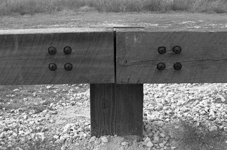
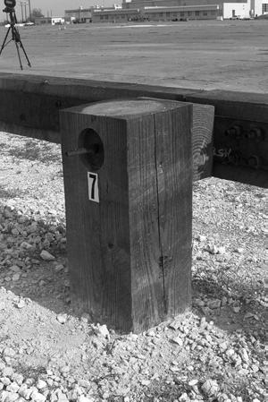
12 The transition section of the guardrail installation was 6 m long and consisted of 10 mm thick, double steel plates mounted to the rear of the wood rail elements between posts 2 through 5. In addition, a two-piece wood rub rail (100 mm x 150 mm x 4500 mm and 100 mm x 150 mm x 1650 mm) rough sawn was mounted from the stone masonry guardwall parapet to post 5. The rub rail was blocked-out with 100 mm x 225 mm x 300 mm rough sawn blocks at the first four posts only. The first four wood posts in the transition were 250 mm x 300 mm x 2400 mm rough sawn. The last post in the transition (post 5) and the remaining length-of-need posts were 250 mm x 300 mm x 2100 mm rough sawn. The wood rail elements were 150 mm x 250 mm x 2990 mm rough sawn and were blocked-out using 100 mm x 225 mm x 300 mm blocks. Type A, as tested, is the designation for a blocked-out rail and Type B designates a non-blocked-out system. Each rail element in the length-of-need section was backed with a 10 mm x 150 mm x 2930 mm steel plate bolted to the timber rail with nine M16 x 100 mm lag screws. The composite rail elements were contiguously attached together at each post location using a 10 mm x 150 mm x 750 mm steel splice plate. A splice plate was attached to each post with an M16 x 380 mm carriage bolt with a plate washer and nut. Each end of a rail element was attached to one side of a splice plate using four M20 x 215 mm carriage bolts with hex nut and washer. The overall rail height was 685 mm. The rail installation was terminated with a Type FAT-9 terminal. The FAT-9 terminal is constructed using the same rail and splice components as the standard length-of-need rail section but is flared both laterally and vertically and anchored below grade. The lateral flare rate was 13:1. A 675 mm x 675 mm x 750 mm concrete anchor block was placed 100 mm below grade for attaching the last rail element. Figure 1 illustrates the construction details of the steel-backed timber guardrail transition to the stone masonry guardwall parapet, the length-of-need section and Type FAT-9 terminal. Test Conditions According to NCHRP Report 350, two tests are recommended to evaluate longitudinal barriers, such as guardrails and bridge rails, to test level four (TL-3) and are as described below. NCHRP Report 350 test designation 3-10: An 820-kg passenger car impacting the critical impact point in the length of need of the longitudinal barrier at a nominal speed and angle of 100 km/h and 20 degrees. The purpose of this test is to evaluate the overall performance of the LON section in general, and occupant risks in particular. NCHRP Report 350 test designation 3-11: A 2000-kg pickup truck impacting the CIP in the LON of the longitudinal barrier at a nominal speed and angle of 100 km/h and 25 degrees. The test is intended to evaluate the strength of section in containing and redirecting the pickup truck. 4
13 5 Figure 1. Details of the steel-backed timber guardrail.
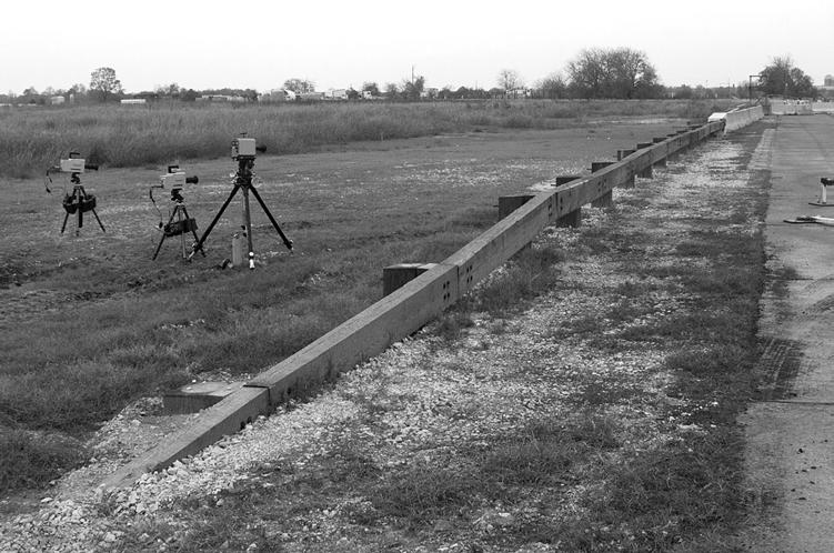
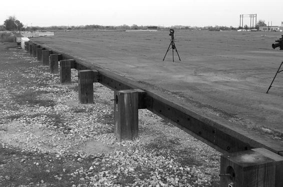
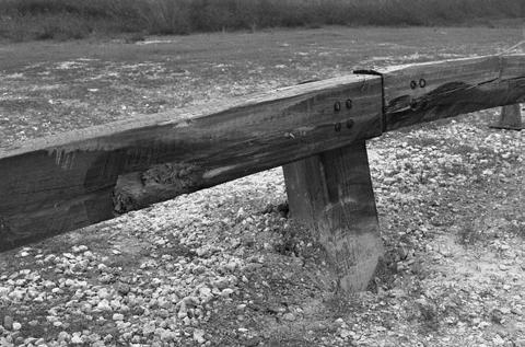
14 Figure 2. Steel-backed timber guardrail prior to testing. 6
15 The crash test reported herein corresponds to the pickup truck test, NCHRP Report 350 test designation The CIP chosen for this test was selected using the information in NCHRP Report 350, and was determined to be 1.5 m upstream of the post/splice nearest the one-third point. The crash test and data analysis procedures were in accordance with guidelines presented in NCHRP Report 350. Appendix A presents brief descriptions of these procedures. Evaluation Criteria The crash test performed was evaluated in accordance with the criteria presented in NCHRP Report 350. As stated in NCHRP Report 350, Safety performance of a highway appurtenance cannot be measured directly but can be judged on the basis of three factors: structural adequacy, occupant risk, and vehicle trajectory after collision. Safety evaluation criteria from table 5.1 of NCHRP Report 350 were used to evaluate the crash test reported herein. 7
16
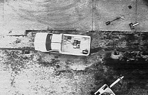
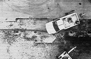
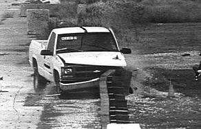
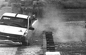
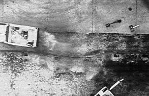
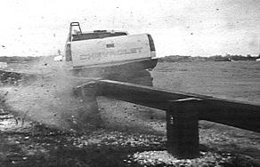
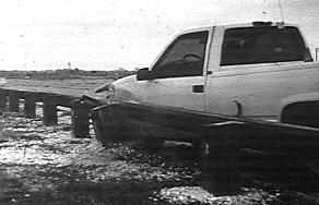
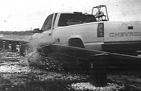
17 CRASH TEST (NCHRP REPORT 350 TEST NO. 3-11) Test Vehicle A 1996 Chevrolet 2500 pickup truck, shown in figures 3 and 4, was used for the crash test. Test inertia weight of the vehicle was 2000 kg, and its gross static weight was 2075 kg. The height to the lower edge of the vehicle front bumper was 395 mm, and to the upper edge of the front bumper was 600 mm. Additional dimensions and information on the vehicle are given in appendix B, figure 10. The vehicle was directed into the installation using the cable reverse tow and guidance system, and was released to be free-wheeling and unrestrained just prior to impact. Soil and Weather Conditions The crash test was performed the morning of December 11, Ten days before the test 2 mm of rainfall was recorded and five days before the test an additional 6 mm was recorded. Moisture content of the NCHRP Report 350 soil in which the test article was installed was 9.9 percent, 10.4 percent, and 10.2 percent at posts 4, 6, and 8, respectively. Weather conditions at the time of testing were as follows: wind speed: 27 km/h; wind direction: 10 degrees with respect to the vehicle (vehicle was traveling in a northwesterly direction); temperature: 13 EC; relative humidity: 69 percent. Impact Description The 2000P vehicle, traveling 98.7 km/h, impacted the steel-backed timber guardrail at an impact angle of 24.5 degrees, 1.35 m upstream of post 6. Posts 6 and 5 moved at s and s, respectively. The vehicle began to redirect at s. At s, the left front tire reached post 6, and at s post 7 moved. The rear of the vehicle contacted the rail element at s. The vehicle was traveling parallel with the guardrail at s at a speed of 67.5 km/h. At s the vehicle lost contact with the guardrail and was traveling at a speed of 58.2 km/h and an exit angle of 9.5 degrees. Brakes on the vehicle were not applied and the vehicle subsequently came to rest 50.3 m downstream of impact and aligned with the front face of the guardrail. Sequential photographs of the test period are shown in appendix C, figures 11 and 12. 9

18 Figure 3. Vehicle/installation geometrics for test


19 Figure 4. Vehicle before test
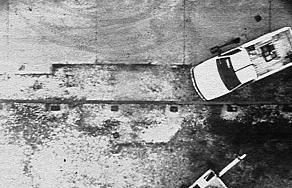
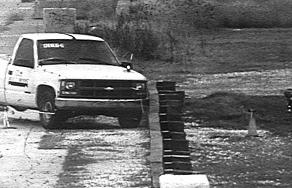
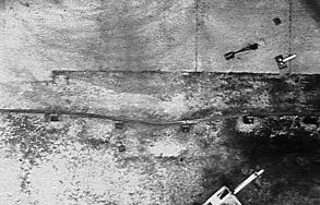
20 Damage to Test Article The steel-backed timber guardrail sustained minimal damage as shown in figures 5 and 6. The rail was fractured on the tension side of the member at the point of maximum deflection between post 6 and 7. The upstream terminal showed no sign of movement and posts 3 through 5 were only disturbed. Post 6 was pushed rearward 245 mm and pulled upward 50 mm; post 7 was pushed rearward 155 mm and pulled upward 110 mm; and post 8 was disturbed and pulled upward 95 mm. Length of contact of the vehicle with the guardrail was 2.2 m. Maximum dynamic deflection of the timber guardrail during the test was 580 mm and maximum permanent deformation after the test was 315 mm. Vehicle Damage Damage to the vehicle is shown in figure 7. Structural damage was imparted to the left tie rod ends and A-arms, stabilizer bar and left front of the frame. The windshield received stress cracking and the floor pan was buckled. Also deformed was the front bumper, grill, hood, left front quarter panel, left front tire and wheel, left door, left rear side of the bed and the left rear tire and wheel. Maximum exterior crush to the vehicle was 380 mm to the left front corner at bumper height. Maximum occupant compartment deformation was 88 mm in the center floor pan area over the transmission tunnel. Photographs of the interior of the vehicle before and after the test are shown in figure 8. Exterior vehicle crush and occupant compartment measurements are shown in appendix B, tables 2 and 3. Occupant Risk Factors Data from the triaxial accelerometer, located at the vehicle c.g., were digitized to compute occupant impact velocity and ridedown accelerations. The occupant impact velocity and ridedown accelerations in the longitudinal axis only are required from these data for evaluation of criterion L of NCHRP Report 350. In the longitudinal direction, occupant impact velocity was 5.1 m/s at s, maximum s ridedown acceleration was g s from to s, and the maximum s average was -6.5 g s between and s. In the lateral direction, the occupant impact velocity was 5.4 m/s at s, the highest s occupant ridedown acceleration was 16.4 g s from to s, and the maximum s average was 8.0 g s between and s. These data and other information pertinent to the test are presented in figure 9. Vehicle angular displacements and accelerations versus time traces are shown in appendix D, figures 13 through


21 Figure 5. Vehicle trajectory after test
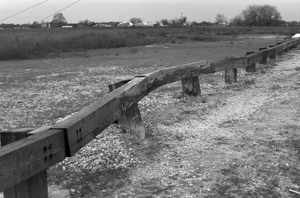
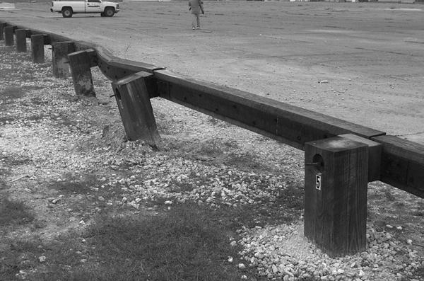
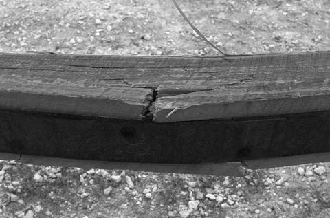
22 Figure 6. Installation after test


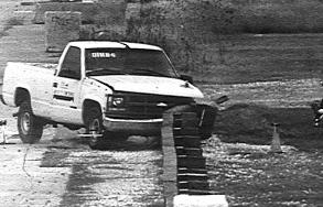
23 Figure 7. Vehicle after test


24 Before test After test Figure 8. Interior of vehicle for test
 Curb... Test Inertial... Dummy... Gross Static... Texas Transportation Institute 405181-2 12/11/00 Guardrail Steel Backed Timber Guardrail 49.")
... Exit Conditions Speed (km/h)... Angle (deg)... Occupant Risk Values Impact Velocity (m/s) x-direction... y-direction... THIV (km/h)... Ridedown Accelerations (g's) x-direction.")
 Dynamic... Permanent........ Working Width... Vehicle Damage Exterior VDS... CDC... Maximum Exterior Vehicle Crush (mm)... Interior OCDI... Max. Occ. Compart.")
25 0.000 s s s s 17 General Information Test Agency... Test No... Date... Test Article Type... Name... Installation Length (m)... Material or Key Elements.. Soil Type and Condition... Test Vehicle Type... Designation... Model... Mass (kg) Curb... Test Inertial... Dummy... Gross Static... Texas Transportation Institute /11/00 Guardrail Steel Backed Timber Guardrail 49.2 Steel-Backed Timber Guardrail Attached to Stone Masonry Guardwall Parapet Standard Soil, Dry Production 2000P 1996 Chevrolet 2500 pickup truck Impact Conditions Speed (km/h)... Angle (deg)... Exit Conditions Speed (km/h)... Angle (deg)... Occupant Risk Values Impact Velocity (m/s) x-direction... y-direction... THIV (km/h)... Ridedown Accelerations (g's) x-direction... y-direction... PHD (g s)... ASI... Max s Average (g's) x-direction... y-direction... z-direction Test Article Deflections (m) Dynamic... Permanent Working Width... Vehicle Damage Exterior VDS... CDC... Maximum Exterior Vehicle Crush (mm)... Interior OCDI... Max. Occ. Compart. Deformation (mm)... Post-Impact Behavior (during 1.0 s after impact) Max. Yaw Angle (deg)... Max. Pitch Angle (deg)... Max. Roll Angle (deg) LFQ2 11FLEK2 &11LYEW2 380 LF Figure 9. Summary of results for test , NCHRP Report 350 test 3-11.
26
27 SUMMARY AND CONCLUSIONS ASSESSMENT OF TEST RESULTS An assessment of the test based on the applicable NCHRP Report 350 safety evaluation criteria is provided below.! Structural Adequacy A. Test article should contain and redirect the vehicle; the vehicle should not penetrate, underride, or override the installation although controlled lateral deflection of the test article is acceptable. Result: The steel-backed timber guardrail contained and redirected the 2000P vehicle. The vehicle did not penetrate, underride, or override the installation. Maximum dynamic deflection was 580 mm.! Occupant Risk D. Detached elements, fragments, or other debris from the test article should not penetrate or show potential for penetrating the occupant compartment, or present an undue hazard to other traffic, pedestrians, or personnel in a work zone. Deformation of, or intrusions into, the occupant compartment that could cause serious injuries should not be permitted. Result: No detached elements, fragments, or other debris were present to penetrate or to show potential for penetrating the occupant compartment, or to present undue hazard to others in the area. Maximum deformation of the occupant compartment was 88 mm. F. The vehicle should remain upright during and after collision although moderate roll, pitching, and yawing are acceptable. Result: The vehicle remained upright during and after the collision period.! Vehicle Trajectory K. After collision, it is preferable that the vehicle s trajectory not intrude into adjacent traffic lanes. Result: The vehicle came to rest 50.3 m downstream of impact and in line with the face of the guardrail. 19
28 L. The occupant impact velocity in the longitudinal direction should not exceed 12 m/s and the occupant ridedown acceleration in the longitudinal direction should not exceed 20 G s. Result: Longitudinal occupant impact velocity was 5.1 m/s and longitudinal ridedown acceleration was g s. M. The exit angle from the test article preferably should be less than 60 percent of the test impact angle, measured at time of vehicle loss of contact with the test device. Result: Exit angle at loss of contact with the guardrail was 9.5 degrees, which was 39 percent of the impact angle. The following supplemental evaluation factors and terminology, as presented in the FHWA memo entitled Action: Identifying Acceptable Highway Safety Features, were used for visual assessment of test results: PASSENGER COMPARTMENT INTRUSION 1. Windshield Intrusion a. No windshield contact b. Windshield contact, no damage c. Windshield contact, no intrusion d. Device embedded in windshield, no significant intrusion e. Complete intrusion into passenger compartment f. Partial intrusion into passenger compartment 2. Body Panel Intrusion yes or no LOSS OF VEHICLE CONTROL 1. Physical loss of control 3. Perceived threat to other vehicles 2. Loss of windshield visibility 4. Debris on pavement PHYSICAL THREAT TO WORKERS OR OTHER VEHICLES 1. Harmful debris that could injure workers or others in the area 2. Harmful debris that could injure occupants in other vehicles No debris was present. 20
29 VEHICLE AND DEVICE CONDITION 1. Vehicle Damage a. None b. Minor scrapes, scratches or dents c. Significant cosmetic dents d. Major dents to grill and body panels e. Major structural damage 2. Windshield Damage a. None b. Minor chip or crack (stress only) c. Broken, no interference with visibility d. Broken and shattered, visibility restricted but remained intact e. Shattered, remained intact but partially dislodged f. Large portion removed g. Completely removed 3. Device Damage a. None b. Superficial c. Substantial, but can be straightened d. Substantial, replacement parts needed for repair e. Cannot be repaired CONCLUSIONS The steel-backed timber guardrail met the required performance criteria specified for test designation 3-11 of NCHRP Report 350, as shown in table 1. 21
30 Table 1. Performance evaluation summary for test , NCHRP Report 350 test Test Agency: Texas Transportation Institute Test No.: Test Date: 12/11/2000 NCHRP Report 350 Evaluation Criteria Test Results Assessment Structural Adequacy A. Test article should contain and redirect the vehicle; the vehicle should not penetrate, underride, or override the installation although controlled lateral deflection of the test article is acceptable. Occupant Risk D. Detached elements, fragments, or other debris from the test article should not penetrate or show potential for penetrating the occupant compartment, or present an undue hazard to other traffic, pedestrians, or personnel in a work zone. Deformations of, or intrusions into, the occupant compartment that could cause serious injuries should not be permitted. F. The vehicle should remain upright during and after collision although moderate roll, pitching, and yawing are acceptable. Vehicle Trajectory K. After collision, it is preferable that the vehicle's trajectory not intrude into adjacent traffic lanes. L. The occupant impact velocity in the longitudinal direction should not exceed 12 m/s and the occupant ridedown acceleration in the longitudinal direction should not exceed 20 g's. M. The exit angle from the test article preferably should be less than 60 percent of test impact angle, measured at time of vehicle loss of contact with test device. *Criterion K and M are preferable, not required. The steel-backed timber guardrail contained and redirected the 2000P vehicle. The vehicle did not penetrate, underride, or override the installation. Maximum dynamic deflection was 580 mm. No detached elements, fragments, or other debris were present to penetrate or to show potential for penetrating the occupant compartment, or to present undue hazard to others in the area. Maximum deformation of the occupant compartment was 88 mm. The vehicle remained upright during and after the collision period. The vehicle came to rest 50.3 m downstream of impact and in line with the face of the guardrail. Longitudinal occupant impact velocity was 5.1 m/s and longitudinal ridedown acceleration was g s. Exit angle at loss of contact with the guardrail was 9.5 degrees, which was 39 percent of the impact angle. Pass Pass Pass Pass* Pass Pass*
31 APPENDIX A. CRASH TEST PROCEDURES AND DATA ANALYSIS The crash test and data analysis procedures were in accordance with guidelines presented in NCHRP Report 350. Brief descriptions of these procedures are presented as follows. ELECTRONIC INSTRUMENTATION AND DATA PROCESSING The test vehicle was instrumented with three solid-state angular rate transducers to measure roll, pitch, and yaw rates; a triaxial accelerometer near the vehicle center of gravity (c.g.) to measure longitudinal, lateral, and vertical acceleration levels; and a back-up biaxial accelerometer in the rear of the vehicle to measure longitudinal and lateral acceleration levels. These accelerometers were ENDEVCO Model 2262CA, piezoresistive accelerometers with a ±100 g range. The accelerometers are strain gage type with a linear millivolt output proportional to acceleration. Angular rate transducers are solid state, gas flow units designed for high- g service. Signal conditioners and amplifiers in the test vehicle increase the low level signals to a ±2.5 volt maximum level. The signal conditioners also provide the capability of an R-Cal or shunt calibration for the accelerometers and a precision voltage calibration for the rate transducers. The electronic signals from the accelerometers and rate transducers are transmitted to a base station by means of a 15 channel, constant bandwidth, Inter-Range Instrumentation Group (I.R.I.G.), FM/FM telemetry link for recording on magnetic tape and for display on a realtime strip chart. Calibration signals, from the test vehicle, are recorded before the test and immediately afterwards. A crystal controlled time reference signal is simultaneously recorded with the data. Pressure-sensitive switches on the bumper of the impacting vehicle are actuated prior to impact by wooden dowels to indicate the elapsed time over a known distance to provide a measurement of impact velocity. The initial contact also produces an event mark on the data record to establish the instant of contact with the installation. The multiplex of data channels, transmitted on one radio frequency, is received and demultiplexed onto separate tracks of a 28 track, (I.R.I.G.) tape recorder. After the test, the data are played back from the tape machine and digitized. A proprietary software program (WinDigit) converts the analog data from each transducer into engineering units using the R-cal and pre-zero values at 10,000 samples per second per channel. WinDigit also provides SAE J211 class 180 phaseless digital filtering and vehicle impact velocity. All accelerometers are calibrated annually according to SAE J by means of an ENDEVCO 2901, precision primary vibration standard. This device and its support instruments are returned to the factory annually for a National Institute of Standards Technology (NIST) traceable calibration. The subsystems of each data channel are also evaluated annually, using instruments with current NIST traceability, and the results factored into the accuracy of the total data channel, per SAE J211. Calibrations and evaluations are made any time data are suspect. 23
32 The Test Risk Assessment Program (TRAP) uses the data from WinDigit to compute occupant/compartment impact velocities, time of occupant/compartment impact after vehicle impact, and the highest 10-ms average ridedown acceleration. WinDigit calculates change in vehicle velocity at the end of a given impulse period. In addition, maximum average accelerations over 50-ms intervals in each of the three directions are computed. For reporting purposes, the data from the vehicle-mounted accelerometers are filtered with a 60-Hz digital filter and acceleration versus time curves for the longitudinal, lateral, and vertical directions are plotted using TRAP. TRAP uses the data from the yaw, pitch, and roll rate transducers to compute angular displacement in degrees at s intervals and then plots: yaw, pitch, and roll versus time. These displacements are in reference to the vehicle-fixed coordinate system with the initial position and orientation of the vehicle-fixed coordinate system being initial impact. ANTHROPOMORPHIC DUMMY INSTRUMENTATION An Alderson Research Laboratories Hybrid II, 50th percentile male anthropomorphic dummy, restrained with lap and shoulder belts, is placed in the driver's position of 820C test vehicles. The dummy is uninstrumented. Use of a dummy in the 2000P vehicle is optional according to NCHRP Report 350 and there was no dummy used in the tests with the 2000P vehicle. PHOTOGRAPHIC INSTRUMENTATION AND DATA PROCESSING Photographic coverage of the test included three high-speed cameras: one overhead with a field of view perpendicular to the ground and directly over the impact point; one placed behind the installation at an angle; and a third placed to have a field of view parallel to and aligned with the installation at the downstream end. A flash bulb activated by pressure-sensitive tape switches is positioned on the impacting vehicle to indicate the instant of contact with the installation and is visible from each camera. The films from these high-speed cameras were analyzed on a computer-linked Motion Analyzer to observe phenomena occurring during the collision and to obtain event time, displacement, and angular data. A 16-mm movie cine, a BetaCam, a VHSformat video camera, and still cameras were used to document conditions of the test vehicle and installation before and after the test. TEST VEHICLE PROPULSION AND GUIDANCE The test vehicle was towed into the test installation using a steel cable guidance and reverse tow system. A steel cable for guiding the test vehicle is tensioned along the path, anchored at each end, and threaded through an attachment to the front wheel of the test vehicle. An additional steel cable is connected to the test vehicle, passed around a pulley near the impact point, through a pulley on the tow vehicle, and then anchored to the ground so the tow vehicle 24
33 moves away from the test site. A two-to-one speed ratio between the test and tow vehicle exists with this system. Just prior to impact with the installation, the test vehicle was released to be free-wheeling and unrestrained. The vehicle remains free-wheeling, i.e., no steering or braking inputs, until the vehicle clears the immediate area of the test site, at which time brakes on the vehicle are activated bringing it to a safe and controlled stop. 25
34
35 APPENDIX B. TEST VEHICLE PROPERTIES AND INFORMATION Figure 10. Vehicle properties for test
36 Table 2. Exterior crush measurements for test VEHICLE CRUSH MEASUREMENT SHEET 1 Complete When Applicable End Damage Side Damage Undeformed end width Bowing: B1 X1 Corner shift: A1 B2 X2 A2 End shift at frame (CDC) (check one) < 4 inches 4 inches Bowing constant X1 % X2 2 ' Note: Measure C1 to C6 from Driver to Passenger side in Front or Rear impacts Rear to Front in Side impacts. Direct Damage Specific Impact Number Plane* of C-Measurements Width ** (CDC) Max** * Crush Field L** C 1 C 2 C 3 C 4 C 5 C 6 ±D 1 Front bumper mm above ground N/A N/A N/A Wheel Well 1 Table taken from National Accident Sampling System (NASS). *Identify the plane at which the C-measurements are taken (e.g., at bumper, above bumper, at sill, above sill, at beltline, etc.) or label adjustments (e.g., free space). Free space value is defined as the distance between the baseline and the original body contour taken at the individual C locations. This may include the following: bumper lead, bumper taper, side protrusion, side taper, etc. Record the value for each C-measurement and maximum crush. **Measure and document on the vehicle diagram the beginning or end of the direct damage width and field L (e.g., side damage with respect to undamaged axle). ***Measure and document on the vehicle diagram the location of the maximum crush. Note: Use as many lines/columns as necessary to describe each damage profile. Table 3. Occupant compartment measurements for test
37 T r u c k O c c u p a n t C o m p a r t m e n t D e f o r m a t i o n BEFORE AFTER A A A B B B C C C D D D E E F G H I J
38

39 APPENDIX C. SEQUENTIAL PHOTOGRAPHS s s s s Figure 11. Sequential photographs for test (overhead and frontal views). 31


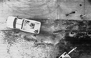
40 0.422 s s s s Figure 11. Sequential photographs for test (overhead and frontal views) (continued). 32


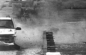
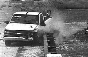
41 0.000 s s s s s s s s Figure 12. Sequential photographs for test (rear view). 33
42
43 40 Roll, Pitch and Yaw Angles 35 Angles (degrees) Roll Pitch Yaw Time (sec) Test Article: Steel backed timber guardrail Test Vehicle: 1996 Chevrolet 2500 pickup truck Inertial Mass: 2000 kg Gross Mass: 2075 kg Impact Speed: 98.7 km/h Impact Angle: 24.5 degrees APPENDIX D. VEHICLE ANGULAR DISPLACEMENTS AND ACCELERATIONS Figure 13. Vehicular angular displacements for test
44 X Acceleration at CG Longitudinal Acceleration (g's) Test Article: Steel backed timber guardrail Test Vehicle: 1996 Chevrolet 2500 pickup truck Inertial Mass: 2000 kg Gross Mass: 2075 kg Impact Speed: 98.7 km/h Impact Angle: 24.5 degrees Time (sec) SAE Class 60 Filter Figure 14. Vehicle longitudinal accelerometer trace for test (accelerometer located at center of gravity).
45 Y Acceleration at CG Lateral Acceleration (g's) Test Article: Steel backed timber guardrail Test Vehicle: 1996 Chevrolet 2500 pickup truck Inertial Mass: 2000 kg Gross Mass: 2075 kg Impact Speed: 98.7 km/h Impact Angle: 24.5 degrees Time (sec) SAE Class 60 Filter Figure 15. Vehicle lateral accelerometer trace for test (accelerometer located at center of gravity).
46 Z Acceleration at CG Vertical Acceleration (g's) Test Article: Steel backed timber guardrail Test Vehicle: 1996 Chevrolet 2500 pickup truck Inertial Mass: 2000 kg Gross Mass: 2075 kg Impact Speed: 98.7 km/h Impact Angle: 24.5 degrees Time (sec) SAE Class 60 Filter Figure 16. Vehicle vertical accelerometer trace for test (accelerometer located at center of gravity).
47 30 X Acceleration Over Rear Axle 39 Longitudinal Acceleration (g's) Test Article: Steel backed timber guardrail Test Vehicle: 1996 Chevrolet 2500 pickup truck Inertial Mass: 2000 kg Gross Mass: 2075 kg Impact Speed: 98.7 km/h Impact Angle: 24.5 degrees Time (sec) SAE Class 60 Filter Figure 17. Vehicle longitudinal accelerometer trace for test (accelerometer located over rear axle).
48 Y Acceleration Over Rear Axle Lateral Acceleration (g's) Test Article: Steel backed timber guardrail Test Vehicle: 1996 Chevrolet 2500 pickup truck Inertial Mass: 2000 kg Gross Mass: 2075 kg Impact Speed: 98.7 km/h Impact Angle: 24.5 degrees Time (sec) SAE Class 60 Filter Figure 18. Vehicle lateral accelerometer trace for test (accelerometer located over rear axle).
49 Z Acceleration Over Rear Axle Vertical Acceleration (g's) Test Article: Steel backed timber guardrail Test Vehicle: 1996 Chevrolet 2500 pickup truck Inertial Mass: 2000 kg Gross Mass: 2075 kg Impact Speed: 98.7 km/h Impact Angle: 24.5 degrees Time (sec) SAE Class 60 Filter Figure 19. Vehicle vertical accelerometer trace for test (accelerometer located over rear axle).
50
51 REFERENCES 1. H. E. Ross, Jr., D. L. Sicking, R. A. Zimmer and J. D. Michie, Recommended Procedures for the Safety Performance Evaluation of Highway Features, National Cooperative Highway Research Program Report 350, Transportation Research Board, National Research Council, Washington, D.C.,
52 23
NCHRP Report 350 Test 4-12 of the Modified Thrie Beam Guardrail
 NCHRP Report 350 Test 4-12 of the Modified Thrie Beam Guardrail PUBLICATION NO. FHWA-RD-99-065 DECEMBER 1999 Research, Development, and Technology Turner-Fairbank Highway Research Center 6300 Georgetown
TEXAS TRANSPORTATION INSTITUTE THE TEXAS A & M UNIVERSITY SYSTEM COLLEGE STATION, TEXAS 77843
 NCHRP REPORT 350 ASSESSMENT OF EXISTING ROADSIDE SAFETY HARDWARE by C. Eugene Buth, P.E. Senior Research Engineer Wanda L. Menges Associate Research Specialist and Sandra K. Schoeneman Research Associate
TEXAS TRANSPORTATION INSTITUTE THE TEXAS A & M UNIVERSITY SYSTEM COLLEGE STATION, TEXAS 77843
 NCHRP REPORT 350 TEST 3-11 OF THE NEW YORK DOT PORTABLE CONCRETE BARRIER WITH I-BEAM CONNECTION (RETEST) by Roger P. Bligh, P.E. Assistant Research Engineer Wanda L. Menges Associate Research Specialist
GUARDRAIL TESTING MODIFIED ECCENTRIC LOADER TERMINAL (MELT) AT NCHRP 350 TL-2. Dean C. Alberson, Wanda L. Menges, and Rebecca R.
 AT NCHRP 350 TL-2. Dean C. Alberson, Wanda L. Menges, and Rebecca R.") GUARDRAIL TESTING MODIFIED ECCENTRIC LOADER TERMINAL (MELT) AT NCHRP 350 TL-2 Dean C. Alberson, Wanda L. Menges, and Rebecca R. Haug Prepared for The New England Transportation Consortium July 2002 NETCR
GUARDRAIL TESTING MODIFIED ECCENTRIC LOADER TERMINAL (MELT) AT NCHRP 350 TL-2 Dean C. Alberson, Wanda L. Menges, and Rebecca R. Haug Prepared for The New England Transportation Consortium July 2002 NETCR
Texas Transportation Institute The Texas A&M University System College Station, Texas
 1. Report No. FHWA/TX-05/9-8132-P7 4. Title and Subtitle TL-4 CRASH TESTING OF THE F411 BRIDGE RAIL 2. Government Accession No. 3. Recipient's Catalog No. 5. Report Date October 2004 Technical Report Documentation
TEXAS TRANSPORTATION INSTITUTE THE TEXAS A & M UNIVERSITY SYSTEM COLLEGE STATION, TEXAS
 NCHRP REPORT 350 TEST 4-21 OF THE ALASKA MULTI-STATE BRIDGE RAIL THRIE-BEAM TRANSITION by C. Eugene Buth Senior Research Engineer William F. Williams Assistant Research Engineer Wanda L. Menges Associate
NCHRP Report 350 Crash Testing and Evaluation of the S-Square Mailbox System
 TTI: 0-5210 NCHRP Report 350 Crash Testing and Evaluation of the S-Square Mailbox System ISO 17025 Laboratory Testing Certificate # 2821.01 Crash testing performed at: TTI Proving Ground 3100 SH 47, Building
Form DOT F (8-72) Texas Transportation Institute The Texas A&M University System College Station, Texas
 Texas Transportation Institute The Texas A&M University System College Station, Texas") 1. Report No. FHWA/TX-02/4162-1 Technical Report Documentation Page 2. Government Accession No. 3. Recipient's Catalog No. 4. Title and Subtitle EVALUATION OF TEXAS GRID-SLOT PORTABLE CONCRETE BARRIER
1. Report No. FHWA/TX-02/4162-1 Technical Report Documentation Page 2. Government Accession No. 3. Recipient's Catalog No. 4. Title and Subtitle EVALUATION OF TEXAS GRID-SLOT PORTABLE CONCRETE BARRIER
MASH08 TEST 3-11 OF THE ROCKINGHAM PRECAST CONCRETE BARRIER
 Proving Ground Report No. 400001-RPC4 Report Date: July 2009 MASH08 TEST 3-11 OF THE ROCKINGHAM PRECAST CONCRETE BARRIER by C. Eugene Buth, P.E. Research Engineer William F. Williams, P.E. Assistant Research
NCHRP REPORT 350 TEST 4-12 OF THE MASSACHUSETTS S3-TL4 STEEL BRIDGE RAILING MOUNTED ON CURB AND SIDEWALK
 TEXAS TRANSPORTATION INSTITUTE NCHRP REPORT 350 TEST 4-12 OF THE MASSACHUSETTS S3-TL4 STEEL BRIDGE RAILING MOUNTED ON CURB AND SIDEWALK by C. Eugene Buth Research Engineer and Wanda L. Menges Associate
Texas Transportation Institute The Texas A&M University System College Station, Texas
 1. Report No. FHWA/TX-04/9-8132-1 4. Title and Subtitle TESTING AND EVALUATION OF THE FLORIDA JERSEY SAFETY SHAPED BRIDGE RAIL 2. Government Accession No. 3. Recipient's Catalog No. 5. Report Date February
CRASH TEST AND EVALUATION OF 3-FT MOUNTING HEIGHT SIGN SUPPORT SYSTEM
 TTI: 9-1002-15 CRASH TEST AND EVALUATION OF 3-FT MOUNTING HEIGHT SIGN SUPPORT SYSTEM ISO 17025 Laboratory Testing Certificate # 2821.01 Crash testing performed at: TTI Proving Ground 3100 SH 47, Building
MASH TEST 3-37 OF THE TxDOT 31-INCH W-BEAM DOWNSTREAM ANCHOR TERMINAL
 TTI: 9-1002 MASH TEST 3-37 OF THE TxDOT 31-INCH W-BEAM DOWNSTREAM ANCHOR TERMINAL ISO 17025 Laboratory Testing Certificate # 2821.01 Crash testing performed at: TTI Proving Ground 3100 SH 47, Building
MASH Test 3-11 on the T131RC Bridge Rail
 TTI: 9-1002-12 MASH Test 3-11 on the T131RC Bridge Rail ISO 17025 Laboratory Testing Certificate # 2821.01 Crash testing performed at: TTI Proving Ground 3100 SH 47, Building 7091 Bryan, TX 77807 Test
A MASH Compliant W-Beam Median Guardrail System
 0 0 0 0 0 A MASH Compliant W-Beam Median Guardrail System By A. Y. Abu-Odeh, R. P. Bligh, W. Odell, A. Meza, and W. L. Menges Submitted: July 0, 0 Word Count:, + ( figures + tables=,000) =, words Authors:
Texas Transportation Institute The Texas A&M University System College Station, Texas
 2. Government Accession No. 3. Recipient's Catalog No. 1. Report No. FHWA/TX-03/0-4138-3 4. Title and Subtitle PERFORMANCE OF THE TXDOT T202 (MOD) BRIDGE RAIL REINFORCED WITH FIBER REINFORCED POLYMER BARS
STI Project: Barrier Systems, Inc. RTS-QMB Longitudinal Barrier. Page 38 of 40 QBOR1. Appendix F (Continued) Figure F-3
 Figure F-3") Barrier Systems, Inc. RTS-QMB Longitudinal Barrier STI Project: QBOR1 Page 38 of 40 Appendix F (Continued) Figure F-3 t=.500sec 115 meters overall 37.1 Impact Severity (kj).. 141.6 Angle (deg).. 25 Speed
Barrier Systems, Inc. RTS-QMB Longitudinal Barrier STI Project: QBOR1 Page 38 of 40 Appendix F (Continued) Figure F-3 t=.500sec 115 meters overall 37.1 Impact Severity (kj).. 141.6 Angle (deg).. 25 Speed
MASH TEST 3-11 OF THE TxDOT T222 BRIDGE RAIL
 TTI: 9-1002-12 MASH TEST 3-11 OF THE TxDOT T222 BRIDGE RAIL ISO 17025 Laboratory Testing Certificate # 2821.01 Crash testing performed at: TTI Proving Ground 3100 SH 47, Building 7091 Bryan, TX 77807 Test
Texas Transportation Institute The Texas A&M University System College Station, Texas
 1. Report No. FHWA/TX-07/0-5527-1 4. Title and Subtitle DEVELOPMENT OF A LOW-PROFILE TO F-SHAPE TRANSITION BARRIER SEGMENT 2. Government Accession No. 3. Recipient's Catalog No. Technical Report Documentation
Virginia Department of Transportation
 TEST REPORT FOR: Virginia Department of Transportation SKT SP 350 50 (15.24 m) System PREPARED FOR: Virginia Department of Transportation 1401 E. Broad St. Richmond, VA 23219 TEST REPORT NUMBER: REPORT
VULCAN BARRIER TL-3 GENERAL SPECIFICATIONS
 VULCAN BARRIER TL-3 GENERAL SPECIFICATIONS I. GENERAL A. The VULCAN BARRIER TL-3 (VULCAN TL-3) shall be a highly portable and crashworthy longitudinal barrier especially suited for use as a temporary barrier
Manual for Assessing Safety Hardware
 American Association of State Highway and Transportation Officials Manual for Assessing Safety Hardware 2009 vii PREFACE Effective traffic barrier systems, end treatments, crash cushions, breakaway devices,
February 8, In Reply Refer To: HSSD/CC-104
 February 8, 2008 200 New Jersey Avenue, SE. Washington, DC 20590 In Reply Refer To: HSSD/CC-04 Barry D. Stephens, P.E. Sr. Vice President Engineering Energy Absorption Systems, Inc. 367 Cincinnati Avenue
MASH TEST 3-11 OF THE TxDOT SINGLE SLOPE BRIDGE RAIL (TYPE SSTR) ON PAN-FORMED BRIDGE DECK
 ON PAN-FORMED BRIDGE DECK") TTI: 9-1002 MASH TEST 3-11 OF THE TxDOT SINGLE SLOPE BRIDGE RAIL (TYPE SSTR) ON PAN-FORMED BRIDGE DECK ISO 17025 Laboratory Testing Certificate # 2821.01 Crash testing performed at: TTI Proving Ground
TTI: 9-1002 MASH TEST 3-11 OF THE TxDOT SINGLE SLOPE BRIDGE RAIL (TYPE SSTR) ON PAN-FORMED BRIDGE DECK ISO 17025 Laboratory Testing Certificate # 2821.01 Crash testing performed at: TTI Proving Ground
CRASH TEST AND EVALUATION OF TEMPORARY WOOD SIGN SUPPORT SYSTEM FOR LARGE GUIDE SIGNS
 TTI: 9-1002-15 CRASH TEST AND EVALUATION OF TEMPORARY WOOD SIGN SUPPORT SYSTEM FOR LARGE GUIDE SIGNS ISO 17025 Laboratory Testing Certificate # 2821.01 Crash testing performed at: TTI Proving Ground 3100
July 10, Refer to: HSA-10/CC-78A
 July 10, 2003 Refer to: HSA-10/CC-78A Barry D. Stephens, P.E. Senior Vice President of Engineering ENERGY ABSORPTION Systems, Inc. 3617 Cincinnati Avenue Rocklin, California 95765 Dear Mr. Stephens: Your
MASH TEST 3-10 ON 31-INCH W-BEAM GUARDRAIL WITH STANDARD OFFSET BLOCKS
 TTI: 9-1002 MASH TEST 3-10 ON 31-INCH W-BEAM GUARDRAIL WITH STANDARD OFFSET BLOCKS ISO 17025 Laboratory Testing Certificate # 2821.01 Crash testing performed at: TTI Proving Ground 3100 SH 47, Building
VULCAN BARRIER TL-3 GENERAL SPECIFICATIONS
 VULCAN BARRIER TL-3 GENERAL SPECIFICATIONS I. GENERAL A. The VULCAN BARRIER TL-3 (VULCAN TL-3) shall be a highly portable and crashworthy longitudinal barrier especially suited for use as a temporary barrier
Evaluation and Design of ODOT s Type 5 Guardrail with Tubular Backup
 Evaluation and Design of ODOT s Type 5 Guardrail with Tubular Backup Draft Final Report Chuck A. Plaxico, Ph.D. James C. Kennedy, Jr., Ph.D. Charles R. Miele, P.E. for the Ohio Department of Transportation
Technical Report Documentation Page Form DOT F (8-72) Reproduction of completed page authorized
 Reproduction of completed page authorized") 1. Report No. FHWA/TX-05/0-4162-3 4. Title and Subtitle 2. Government Accession No. 3. Recipient's Catalog No. DEVELOPMENT OF LOW-DEFLECTION PRECAST CONCRETE ARRIER 5. Report Date January 2005 Technical
1. Report No. FHWA/TX-05/0-4162-3 4. Title and Subtitle 2. Government Accession No. 3. Recipient's Catalog No. DEVELOPMENT OF LOW-DEFLECTION PRECAST CONCRETE ARRIER 5. Report Date January 2005 Technical
Product Specification. ABSORB 350 TM TL-2 Non-Redirective, Gating, Crash Cushion Applied to Quickchange Moveable Barrier
 TB 000612 Rev. 0 Page 1 of 9 Product Specification ABSORB 350 TM TL-2 Non-Redirective, Gating, Crash Cushion Applied to Quickchange Moveable Barrier I. General The ABSORB 350 TM TL-2 System is a Non-Redirective,
VERIFICATION & VALIDATION REPORT of MGS Barrier Impact with 1100C Vehicle Using Toyota Yaris Coarse FE Model
 VERIFICATION & VALIDATION REPORT of MGS Barrier Impact with 1100C Vehicle Using Toyota Yaris Coarse FE Model CCSA VALIDATION/VERIFICATION REPORT Page 1 of 4 Project: CCSA Longitudinal Barriers on Curved,
Transportation Institute
 .JIIIIIII"" Texas Transportation Institute SUMMARY OF TESTING ON 'l'he RENCO TRUCK MOUNTED ATTENUATOR by Wanda L. Menges Associate Research Specialist C. Eugene Buth, P.E. Senior Research Engineer and
ASTM F TEST M30 ON THE RSS-3000 DROP BEAM SYSTEM
 Proving Ground Test Report No.: 510602-RSS3 Test Report Date: January 2014 ASTM F2656-07 TEST M30 ON THE RSS-3000 DROP BEAM SYSTEM by Dean C. Alberson, Ph.D., P.E. Research Engineer Michael S. Brackin,
MASH TEST 3-21 ON TL-3 THRIE BEAM TRANSITION WITHOUT CURB
 TTI: 9-1002-12 MASH TEST 3-21 ON TL-3 THRIE BEAM TRANSITION WITHOUT CURB ISO 17025 Laboratory Testing Certificate # 2821.01 Crash testing performed at: TTI Proving Ground 3100 SH 47, Building 7091 Bryan,
Universal TAU-IIR Redirective, Non-Gating, Crash Cushion
 TB 110927 Rev. 0 Page 1 of 5 Product Specification Universal TAU-IIR Redirective, Non-Gating, Crash Cushion I. General The Universal TAU-IIR system is a Redirective, Non-Gating Crash Cushion in accordance
TEXAS TRANSPORTATION INSTITUTE THE TEXAS A & M UNIVERSITY SYSTEM COLLEGE STATION, TEXAS
 TEXAS TRANSPORTATION INSTITUTE Test Level 2 Evaluation of the RENCO Ren-Gard 815 Truck Mounted Attenuator by C. Eugene Buth Senior Research Engineer and Wanda L. Menges Associate Research Specialist Contract
Remote Combination Adaptive Driving Equipment Investigation Dynamic Science, Inc. (DSI), Case Number G 1990 Ford Bronco Arizona October
, Case Number G 1990 Ford Bronco Arizona October") Remote Combination Adaptive Driving Equipment Investigation Dynamic Science, Inc. (DSI), Case Number 2007-76-131G 1990 Ford Bronco Arizona October 2007 This document is disseminated under the sponsorship
Remote Combination Adaptive Driving Equipment Investigation Dynamic Science, Inc. (DSI), Case Number 2007-76-131G 1990 Ford Bronco Arizona October 2007 This document is disseminated under the sponsorship
Evaluation of Barriers for Very High Speed Roadways
 TTI: 0-6071 Evaluation of Barriers for Very High Speed Roadways ISO 17025 Laboratory Testing Certificate # 2821.01 Crash testing performed at: TTI Proving Ground 3100 SH 47, Building 7091 Bryan, TX 77807
Sponsored by Roadside Safety Research Program Pooled Fund Study No. TPF-5(114)
") Proving Ground Test Report No. 405160-23-2 Test Report Date: February 2012 MASH TEST 3-11 OF THE W-BEAM GUARDRAIL ON LOW-FILL BOX CULVERT by William F. Williams, P.E. Associate Research Engineer and Wanda
Proving Ground Test Report No. 405160-23-2 Test Report Date: February 2012 MASH TEST 3-11 OF THE W-BEAM GUARDRAIL ON LOW-FILL BOX CULVERT by William F. Williams, P.E. Associate Research Engineer and Wanda
SUMMARY CHANGES FOR NCHRP REPORT 350 GUIDELINES [NCHRP (02)] Keith A. Cota, Chairman Technical Committee on Roadside Safety June 14, 2007
![SUMMARY CHANGES FOR NCHRP REPORT 350 GUIDELINES [NCHRP (02)] Keith A. Cota, Chairman Technical Committee on Roadside Safety June 14, 2007](/thumbs/87/97351925.jpg "SUMMARY CHANGES FOR NCHRP REPORT 350 GUIDELINES [NCHRP (02)] Keith A. Cota, Chairman Technical Committee on Roadside Safety June 14, 2007") SUMMARY CHANGES FOR NCHRP REPORT 350 GUIDELINES [NCHRP 22-14 (02)] Keith A. Cota, Chairman Technical Committee on Roadside Safety June 14, 2007 BACKGROUND Circular 482 (1962) First full scale crash test
SUMMARY CHANGES FOR NCHRP REPORT 350 GUIDELINES [NCHRP 22-14 (02)] Keith A. Cota, Chairman Technical Committee on Roadside Safety June 14, 2007 BACKGROUND Circular 482 (1962) First full scale crash test
SAFETY COMPLIANCE TESTING FOR FMVSS NO. 214S SIDE IMPACT PROTECTION (STATIC)
") REPORT NUMBER 214-GTL-09-002 SAFETY COMPLIANCE TESTING FOR S SIDE IMPACT PROTECTION (STATIC) MAZDA MOTOR CORPORATION 2009 MAZDA 3, PASSENGER CAR NHTSA NO. C95400 GENERAL TESTING LABORATORIES, INC. 1623
REPORT NUMBER 214-GTL-09-002 SAFETY COMPLIANCE TESTING FOR S SIDE IMPACT PROTECTION (STATIC) MAZDA MOTOR CORPORATION 2009 MAZDA 3, PASSENGER CAR NHTSA NO. C95400 GENERAL TESTING LABORATORIES, INC. 1623
Appendix D. Figure D-1. ENCLOSURE 1 (4 Pages) SafeGuard TM Gate System
 SafeGuard TM Gate System") Appendix D Figure D-1 SafeGuard TM Gate System ENCLOSURE 1 (4 Pages) Appendix D (Continued) Figure D-4 SafeGuard TM Gate System Appendix D (Continued) Figure D-9 SafeGuardTM Gate System Page D-9 Figure
Appendix D Figure D-1 SafeGuard TM Gate System ENCLOSURE 1 (4 Pages) Appendix D (Continued) Figure D-4 SafeGuard TM Gate System Appendix D (Continued) Figure D-9 SafeGuardTM Gate System Page D-9 Figure
14. Sponsoring Agency Code McLean, Virginia
 TECHNICAL REPORT DOCUMENTATION PAGE I. Report No. 2. Government Accession No. FHWA-RD-93-069 4. Title and Subtitle TESTING OF NEW BRIDGE RAIL AND TRANSITION DESIGNS Volume XII: Appendix K Oregon Transition
BarrierGate. General Specifications. Manual Operations General Specifications
 BarrierGate General Specifications Manual Operations General Specifications BarrierGate GENERAL SPECIFICATIONS I. GENERAL A. The BarrierGate system (the gate) shall be designed and manufactured by Energy
DEVELOPMENT OF A MASH TL-3 MEDIAN BARRIER GATE
 TTI: 9-1002 DEVELOPMENT OF A MASH TL-3 MEDIAN BARRIER GATE ISO 17025 Laboratory Testing Certificate # 2821.01 Crash testing performed at: TTI Proving Ground 3100 SH 47, Building 7091 Bryan, TX 77807 Research/Test
REPORT NUMBER: 301-CAL SAFETY COMPLIANCE TESTING FOR FMVSS 301 FUEL SYSTEM INTEGRITY HONDA MOTOR COMPANY 2007 HONDA ACCORD 4-DOOR SEDAN
 REPORT NUMBER: 301-CAL-07-05 SAFETY COMPLIANCE TESTING FOR FMVSS 301 FUEL SYSTEM INTEGRITY HONDA MOTOR COMPANY 2007 HONDA ACCORD 4-DOOR SEDAN NHTSA NUMBER: C75304 CALSPAN TEST NUMBER: 8832-F301-05 CALSPAN
Evaluation of the Sequential Dynamic Curve Warning System Summary of Full Report Publication No. FHWA-15-CAI-012-A November 2015
 Evaluation of the Sequential Dynamic Curve Warning System Summary of Full Report Publication No. FHWA-15-CAI-012-A November 2015 Source: ISU/TTI Notice This document is disseminated under the sponsorship
RSA Protective Technologies
 TEST REPORT FOR: RSA Protective Technologies K12 Surface Mounted Bollard System TESTED TO: ASTM F 2656-07 Standard Test Method for Vehicle Crash Testing of Perimeter Barriers Test M50 PREPARED FOR: Battelle
Crash Testing Growth Common Roadside Hardware Systems Draft FHWA and AASHTO Requirements for Implementing MASH 2015
 64 th Annual Illinois Traffic Safety and Engineering Conference October 14, 2015 Crash Testing Growth Common Roadside Hardware Systems Draft FHWA and AASHTO Requirements for Implementing MASH 2015 1 https://www.youtube.com/watch?feature
PERFORMANCE EVALUATION OF THE MODIFIED G4(1S) GUARDRAIL UPDATE TO NCHRP 350 TEST NO WITH 28" C.G. HEIGHT (2214WB-2)
 GUARDRAIL UPDATE TO NCHRP 350 TEST NO WITH 28 C.G. HEIGHT (2214WB-2)") PERFORMANCE EVALUATION OF THE MODIFIED G4(1S) GUARDRAIL UPDATE TO NCHRP 350 TEST NO. 3-11 WITH 28" C.G. HEIGHT (2214WB-2) Submitted by Karla A. Polivka, M.S.M.E., E.I.T. Research Associate Engineer Dean
PERFORMANCE EVALUATION OF THE MODIFIED G4(1S) GUARDRAIL UPDATE TO NCHRP 350 TEST NO. 3-11 WITH 28" C.G. HEIGHT (2214WB-2) Submitted by Karla A. Polivka, M.S.M.E., E.I.T. Research Associate Engineer Dean
PERFORMANCE EVALUATION OF THE FREE-STANDING TEMPORARY BARRIER UPDATE TO NCHRP 350 TEST NO (2214TB-1)
") PERFORMANCE EVALUATION OF THE FREE-STANDING TEMPORARY BARRIER UPDATE TO NCHRP 350 TEST NO. 3-11 (2214TB-1) Submitted by Karla A. Polivka, M.S.M.E., E.I.T. Research Associate Engineer Dean L. Sicking, Ph.D.,
PERFORMANCE EVALUATION OF THE FREE-STANDING TEMPORARY BARRIER UPDATE TO NCHRP 350 TEST NO. 3-11 (2214TB-1) Submitted by Karla A. Polivka, M.S.M.E., E.I.T. Research Associate Engineer Dean L. Sicking, Ph.D.,
FAAC International, Inc.
 TEST REPORT FOR: FAAC International, Inc. J 355 HA M30 (K4) Bollard TESTED TO: ASTM F 2656-07 Standard Test Method for Vehicle Crash Testing of Perimeter Barriers Test M30 PREPARED FOR: FAAC International,
Advances in Simulating Corrugated Beam Barriers under Vehicular Impact
 13 th International LS-DYNA Users Conference Session: Automotive Advances in Simulating Corrugated Beam Barriers under Vehicular Impact Akram Abu-Odeh Texas A&M Transportation Institute Abstract W-beam
REPORT NUMBER: 301-CAL SAFETY COMPLIANCE TESTING FOR FMVSS 301 FUEL SYSTEM INTEGRITY REAR IMPACT FORD MOTOR COMPANY 2009 FORD F150 2-DOOR PICKUP
 REPORT NUMBER: 301-CAL-09-03 SAFETY COMPLIANCE TESTING FOR FMVSS 301 FUEL SYSTEM INTEGRITY REAR IMPACT FORD MOTOR COMPANY 2009 FORD F150 2-DOOR PICKUP NHTSA NUMBER: C90206 CALSPAN TRANSPORTATION SCIENCES
REPORT NUMBER: 301-MGA SAFETY COMPLIANCE TESTING FOR FMVSS 301R FUEL SYSTEM INTEGRITY REAR IMPACT
 REPORT NUMBER: 301-MGA-2010-007 SAFETY COMPLIANCE TESTING FOR FMVSS 301R FUEL SYSTEM INTEGRITY REAR IMPACT NISSAN MOTOR COMPANY LTD 2010 NISSAN CUBE NHTSA NUMBER: CA5205 PREPARED BY: MGA RESEARCH CORPORATION
CRASH TESTING OF RSA/K&C ANTI-RAM FOUNDATION BOLLARD PAD IN ACCORDANCE WITH U.S. DEPARTMENT OF STATE DIPLOMATIC SECURITY SD-STD-02.
 CRASH TESTING OF RSA/K&C ANTI-RAM FOUNDATION BOLLARD PAD IN ACCORDANCE WITH U.S. DEPARTMENT OF STATE DIPLOMATIC SECURITY SD-STD-02.01 REVISION A Prepared for RSA Protective Technologies, LLC FINAL REPORT
CRASH TEST REPORT FOR PERIMETER BARRIERS AND GATES TESTED TO SD-STD-02.01, REVISION A, MARCH Anti-Ram Bollards
 CRASH TEST REPORT FOR PERIMETER BARRIERS AND GATES TESTED TO SD-STD-02.01, REVISION A, MARCH 2003 Anti-Ram Bollards Prepared for: RSA Protective Technologies, LLC 1573 Mimosa Court Upland, CA 91784 Test
REPORT NUMBER: 301-CAL SAFETY COMPLIANCE TESTING FOR FMVSS 301 FUEL SYSTEM INTEGRITY REAR IMPACT MAZDA MOTOR CORPORATION 2008 MAZDA CX-9 SUV
 REPORT NUMBER: 301-CAL-08-03 SAFETY COMPLIANCE TESTING FOR FMVSS 301 FUEL SYSTEM INTEGRITY REAR IMPACT MAZDA MOTOR CORPORATION 2008 MAZDA CX-9 SUV NHTSA NUMBER: C85401 CALSPAN TRANSPORTATION SCIENCES CENTER
CRASH TEST REPORT FOR PERIMETER BARRIERS AND GATES TESTED TO SD-STD-02.01, REVISION A, MARCH Anti-Ram Bollards
 CRASH TEST REPORT FOR PERIMETER BARRIERS AND GATES TESTED TO SD-STD-02.01, REVISION A, MARCH 2003 Anti-Ram Bollards Prepared for: RSA Protective Technologies, LLC 1573 Mimosa Court Upland, CA 91784 Test
June 5, In Reply Refer To: HSSD/B-178. Mr. Kevin K. Groeneweg Mobile Barriers LLC Genesee Trail Road Golden, CO Dear Mr.
 June 5, 2008 1200 New Jersey Avenue, SE. Washington, DC 20590 In Reply Refer To: HSSD/B-178 Mr. Kevin K. Groeneweg Mobile Barriers LLC 24918 Genesee Trail Road Golden, CO 80401 Dear Mr. Groeneweg: This
PERFORMANCE EVALUATION OF THE FREE-STANDING TEMPORARY BARRIER UPDATE TO NCHRP 350 TEST NO WITH 28" C.G. HEIGHT (2214TB-2)
") PERFORMANCE EVALUATION OF THE FREE-STANDING TEMPORARY BARRIER UPDATE TO NCHRP 350 TEST NO. 3-11 WITH 28" C.G. HEIGHT (2214TB-2) Submitted by Karla A. Polivka, M.S.M.E., E.I.T. Research Associate Engineer
PERFORMANCE EVALUATION OF THE FREE-STANDING TEMPORARY BARRIER UPDATE TO NCHRP 350 TEST NO. 3-11 WITH 28" C.G. HEIGHT (2214TB-2) Submitted by Karla A. Polivka, M.S.M.E., E.I.T. Research Associate Engineer
AASHTO Manual for Assessing Safety Hardware, AASHTO/FHWA Joint Implementation Plan Standing Committee on Highways September 24, 2015
 AASHTO Manual for Assessing Safety Hardware, 2015 AASHTO/FHWA Joint Implementation Plan Standing Committee on Highways September 24, 2015 Full Scale MASH Crash Tests (NCHRP 22-14(02)) Conducted several
Development of Combination Pedestrian-Traffic Bridge Railings
 TRANSPORTATION RESEARCH RECORD 1468 41 Development of Combination Pedestrian-Traffic Bridge Railings D. LANCE BULLARD, JR., WANDA L. MENGES, AND C. EUGENE BUTH Two bridge railing designs have been developed
CRASH TEST OF MILE POST MARKER. T. J. Hirsch Research Engineer. and. Eugene Buth Assistant Research Engineer. Research Report Number 146-8
 CRASH TEST OF MILE POST MARKER by T. J. Hirsch Research Engineer and Eugene Buth Assistant Research Engineer Research Report Number 146-8 Studies of Field Adaption of Impact Attenuation Systems Research
OPTIMIZATION OF THRIE BEAM TERMINAL END SHOE CONNECTION
 TTI: 9-1002-15 OPTIMIZATION OF THRIE BEAM TERMINAL END SHOE CONNECTION ISO 17025 Laboratory Testing Certificate # 2821.01 Pendulum testing performed at: TTI Proving Ground 3100 SH 47, Building 7091 Bryan,
PERFORMANCE EVALUATION OF THE PERMANENT NEW JERSEY SAFETY SHAPE BARRIER UPDATE TO NCHRP 350 TEST NO (2214NJ-2)
") PERFORMANCE EVALUATION OF THE PERMANENT NEW JERSEY SAFETY SHAPE BARRIER UPDATE TO NCHRP 350 TEST NO. 4-12 (2214NJ-2) Submitted by Karla A. Polivka, M.S.M.E., E.I.T. Research Associate Engineer Dean L.
PERFORMANCE EVALUATION OF THE PERMANENT NEW JERSEY SAFETY SHAPE BARRIER UPDATE TO NCHRP 350 TEST NO. 4-12 (2214NJ-2) Submitted by Karla A. Polivka, M.S.M.E., E.I.T. Research Associate Engineer Dean L.
REPORT NUMBER: 301-MGA SAFETY COMPLIANCE TESTING FOR FMVSS 301R FUEL SYSTEM INTEGRITY REAR IMPACT
 REPORT NUMBER: 301-MGA-2011-008 SAFETY COMPLIANCE TESTING FOR FMVSS 301R FUEL SYSTEM INTEGRITY REAR IMPACT MAZDA MOTOR CORPORATION 2011 MAZDA 2 SPORT MT NHTSA NUMBER: CB5400 PREPARED BY: MGA RESEARCH CORPORATION
I I TEXAS TRANSPORTATION INSTITUTE THE TEXAS A & M UNIVERSITY SYSTEM COLLEGE STATION, TEXAS
 TEXAS TRANSPORTATON NSTTUTE Testing and Evaluation of the Vermont W-Beam Guardrail Terminal for Low Speed Areas by Althea G. Arnold Assistant Research Engineer Wanda L. Menges Associate Research Specialist
Development and Validation of a Finite Element Model of an Energy-absorbing Guardrail End Terminal
 Development and Validation of a Finite Element Model of an Energy-absorbing Guardrail End Terminal Yunzhu Meng 1, Costin Untaroiu 1 1 Department of Biomedical Engineering and Virginia Tech, Blacksburg,
REPORT NUMBER: 301-MGA SAFETY COMPLIANCE TESTING FOR FMVSS 301R FUEL SYSTEM INTEGRITY REAR IMPACT
 REPORT NUMBER: 301-MGA-2007-002 SAFETY COMPLIANCE TESTING FOR FMVSS 301R FUEL SYSTEM INTEGRITY REAR IMPACT NISSAN MOTOR CO., LTD. 2006 NISSAN PATHFINDER LE 4X2 NHTSA NUMBER: C65200 PREPARED BY: MGA RESEARCH
REPORT NUMBER: 301-CAL SAFETY COMPLIANCE TESTING FOR FMVSS 301 FUEL SYSTEM INTEGRITY REAR IMPACT
 REPORT NUMBER: 301-CAL-09-01 SAFETY COMPLIANCE TESTING FOR FMVSS 301 FUEL SYSTEM INTEGRITY REAR IMPACT HYUNDAI MOTOR COMPANY 2009 HYUNDAI ACCENT 4-DOOR SEDAN NHTSA NUMBER: C90503 CALSPAN TRANSPORTATION
Evaluation of the Midwest Guardrail System Stiffness Transition with Curb
 Duplication for publication or sale is strictly prohibited without prior written permission of the Transportation Research Board Paper No. -0 Evaluation of the Midwest Guardrail System Stiffness Transition
REPORT NO. TR-P NC SAFETY COMPLIANCE TESTING FOR FMVSS 223 REAR IMPACT GUARDS 2007 TRANSFREIGHT TECHNOLOGY NHTSA NO.
 REPORT NO. SAFETY COMPLIANCE TESTING FOR FMVSS 223 REAR IMPACT GUARDS 2007 TRANSFREIGHT TECHNOLOGY NHTSA NO. RIG 009 PREPARED BY: KARCO ENGINEERING, LLC. 9270 HOLLY ROAD ADELANTO, CALIFORNIA 92301 SEPTEMBER
Performance Level 1 Bridge Railings
 80 TRANSPORTATION RESEARCH RECORD 1500 Performance Level 1 Bridge Railings DEAN C. ALBERSON, WANDA L. MENGES, AND C. EUGENE BUTH Twenty-three states, FHW A, and the District of Columbia sponsored the project
PR V2. Submitted by. Professor MIDWEST Vine Street (402) Submitted to
 Submitted to") FINAL REPORT PR4893118-V2 ZONE OF INTRUSION STUDY Submitted by John D. Reid, Ph.D. Professor Dean L.. Sicking, Ph.D., P.E. Professorr and MwRSF Director MIDWEST ROADSIDE SAFETY FACILITY University of Nebraska-Lincoln
FINAL REPORT PR4893118-V2 ZONE OF INTRUSION STUDY Submitted by John D. Reid, Ph.D. Professor Dean L.. Sicking, Ph.D., P.E. Professorr and MwRSF Director MIDWEST ROADSIDE SAFETY FACILITY University of Nebraska-Lincoln
FHW A-RD TESTING OF NEW BRIDGE RAIL AND TRANSITION DESIGNS Volume IX: Appendix H Illinois Side Mount Bridge Railing
 TECHNICAL REPORT DOCUMENTATION PAGE 1. Report No. 2. Goverrunent Accession No. FHW A-RD-93-066 4. Title and Subtitle TESTING OF NEW BRIDGE RAIL AND TRANSITION DESIGNS Volume IX: Appendix H Illinois Side
MASH 2016 Implementation: What, When and Why
 MASH 2016 Implementation: What, When and Why Roger P. Bligh, Ph.D., P.E. Senior Research Engineer Texas A&M Transportation Institute June 7, 2016 2016 Traffic Safety Conference College Station, Texas Outline
REPORT NUMBER: 301-MGA SAFETY COMPLIANCE TESTING FOR FMVSS 301R FUEL SYSTEM INTEGRITY REAR IMPACT
 REPORT NUMBER: 301-MGA-2010-005 SAFETY COMPLIANCE TESTING FOR FMVSS 301R FUEL SYSTEM INTEGRITY REAR IMPACT NISSAN MOTOR COMPANY LTD 2010 NISSAN CUBE NHTSA NUMBER: CA5201 PREPARED BY: MGA RESEARCH CORPORATION
REPORT NUMBER: 111SB-MGA SAFETY COMPLIANCE TESTING FOR FMVSS NO. 111SB SCHOOL BUS REARVIEW MIRRORS
 REPORT NUMBER: 111SB-MGA-2009-001 SAFETY COMPLIANCE TESTING FOR FMVSS NO. 111SB SCHOOL BUS REARVIEW MIRRORS THOMAS BUILT BUSES 2009 THOMAS MINOTOUR SCHOOL BUS NHTSA NO.: C90901 PREPARED BY: MGA RESEARCH
SAFETY COMPLIANCE TESTING FOR FMVSS NO. 225 CHILD RESTRAINT ANCHORAGE SYSTEMS LOWER AND TETHER ANCHORAGES
 REPORT NUMBER 225-GTL-06-006 SAFETY COMPLIANCE TESTING FOR FMVSS NO. 225 CHILD RESTRAINT ANCHORAGE SYSTEMS LOWER AND TETHER ANCHORAGES GENERAL MOTORS OF CANADA, LTD. 2005 BUICK LACROSSE, PASSENGER CAR
Midwest Guardrail System Without Blockouts
 Duplication for publication or sale is strictly prohibited without prior written permission of the Transportation Research Board Paper No. 13-0418 Midwest Guardrail System Without Blockouts by John D.
Final Report Federal Highway Administration August September Georgetown Pike
 TECHNICAL REPORT DOCUMENTATION PAGE 1. Report No. 2. Government Accession No. FHW A-RD-93-065 4. Title and Subtitle TESTING OF NEW BRIDGE RAIL AND TRANSITION DESIGNS Volume VIII: Appendix G BR27C Bridge
CRASH TESTING AND EVALUATION OF WORK ZONE TRAFFIC CONTROL DEVICES
 Paper No. 980627 CRASH TESTING AND EVALUATION OF WORK ZONE TRAFFIC CONTROL DEVICES by King K. Mak Phone: 210-698-2068 Fax: 210-698-2068 e-mail: king@tti3a.tamu.edu Texas Transportation Institute The Texas
ROBUST PROJECT Norwegian Public Roads Administration / Force Technology Norway AS
 ROBUST PROJECT Norwegian Public Roads Administration / Force Technology Norway AS Evaluation of small car - RM_R1 - prepared by Politecnico di Milano Volume 1 of 1 January 2006 Doc. No.: ROBUST-5-002/TR-2004-0039
COMPLIANCE TESTING FOR FMVSS 207 SEATING SYSTEMS
 REPORT NO. COMPLIANCE TESTING FOR FMVSS 207 SEATING SYSTEMS 2008 CHEVROLET IMPALA 4-DOOR NHTSA NO.C80102 PREPARED BY: KARCO ENGINEERING, LLC 9270 HOLLY ROAD ADELANTO, CALIFORNIA 92301 September 24, 2008
Office of Safety & Traffic Operations R&D Federal Highway Administration August September Georgetown Pike
 TECHNICAL REPORT DOCUMENTATION PAGE I. Report No. 2. Government Accession No. FHWA-RD-93-067 4. Title and Subtitle TESTING OF NEW BRIDGE RAIL AND TRANSITION DESIGNS Volume X: Appendix I 42-in (1.07-m)
Assessing Options for Improving Roadside Barrier Crashworthiness
 13 th International LS-DYNA Users Conference Session: Simulation Assessing Options for Improving Roadside Barrier Crashworthiness D. Marzougui, C.D. Kan, and K.S. Opiela Center for Collision Safety and
Remote, Redesigned Air Bag Special Study Dynamic Science, Inc., Case Number ( C) 1998 Nissan Altima Texas August/1998
 1998 Nissan Altima Texas August/1998") Remote, Redesigned Air Bag Special Study Dynamic Science, Inc., Case Number ( 1998-49-136C) 1998 Nissan Altima Texas August/1998 Technical Report Documentation Page 1. Report No. 2. Government Accession
Remote, Redesigned Air Bag Special Study Dynamic Science, Inc., Case Number ( 1998-49-136C) 1998 Nissan Altima Texas August/1998 Technical Report Documentation Page 1. Report No. 2. Government Accession
GENERAL TESTING LABORATORIES, INC LEEDSTOWN ROAD COLONIAL BEACH, VIRGINIA 22443
 REPORT NUMBER 202a-GTL-10-004 SAFETY COMPLIANCE TESTING FOR S HEAD RESTRAINTS STATIC REQUIREMENTS VOLVO CAR CORPORATION 2010 VOLVO S40, PASSENGER CAR NHTSA NO. CA5900 GENERAL TESTING LABORATORIES, INC.
TEST REPORT No. 2 ALUMINUM BRIDGE RAIL SYSTEMS. Prepared for. The Aluminum Association Inc. 818 Connecticut Avenue Washington, D.C.
 TEST REPORT No. 2 ALUMNUM BRDGE RAL SYSTEMS Prepared for The Aluminum Association nc. 818 Connecticut Avenue Washington, D.C. 26 by C. E. Buth Research Engineer G. G. Hayes Assoc. Research Physicist and
Evaluation of the Midwest Guardrail System stiffness transition with curb
 University of Nebraska - Lincoln DigitalCommons@University of Nebraska - Lincoln Civil Engineering Faculty Publications Civil Engineering 2016 Evaluation of the Midwest Guardrail System stiffness transition
SAFETY COMPLIANCE TESTING FOR FMVSS 225 Child Restraint Anchorage Systems
 FINAL REPORT NUMBER 225-MGA-06-007 SAFETY COMPLIANCE TESTING FOR FMVSS 225 TOYOTA MOTOR CORPORATION 2006 TOYOTA HIGHLANDER NHTSA No. C65101 MGA RESEARCH CORPORATION 446 Executive Drive Troy, Michigan 48083
W-Beam Guiderail Transition from Light to Heavy Posts
 TRANSPORTATION RESEARCH RECORD 1198 55 W-Beam Guiderail Transition from Light to Heavy Posts DONALD G. HERRING AND JAMES E. BRYDEN Two full-scale crash tests evaluated a transition between lightand heavy-post
REPORT NUMBER: NCAP305I-MGA NEW CAR ASSESSMENT PROGRAM (NCAP) FMVSS No. 305 Indicant Test
 FMVSS No. 305 Indicant Test") REPORT NUMBER: NCAP305I-MGA-2012-008 NEW CAR ASSESSMENT PROGRAM (NCAP) FMVSS No. 305 Indicant Test GENERAL MOTORS LLC 2013 Chevrolet Malibu ECO4-Dr Hybrid Sedan NHTSA NUMBER: MD0101 MGA RESEARCH CORPORATION
REPORT NUMBER: NCAP305I-MGA-2012-008 NEW CAR ASSESSMENT PROGRAM (NCAP) FMVSS No. 305 Indicant Test GENERAL MOTORS LLC 2013 Chevrolet Malibu ECO4-Dr Hybrid Sedan NHTSA NUMBER: MD0101 MGA RESEARCH CORPORATION
Remote, Redesigned Air Bag Special Study FOR NHTSA S INTERNAL USE ONLY Dynamic Science, Inc., Case Number ( J) 1998 Dodge Caravan Indiana
 1998 Dodge Caravan Indiana") Remote, Redesigned Air Bag Special Study FOR NHTSA S INTERNAL USE ONLY Dynamic Science, Inc., Case Number (1998-073-111J) 1998 Dodge Caravan Indiana September/1998 Technical Report Documentation Page 1.
Remote, Redesigned Air Bag Special Study FOR NHTSA S INTERNAL USE ONLY Dynamic Science, Inc., Case Number (1998-073-111J) 1998 Dodge Caravan Indiana September/1998 Technical Report Documentation Page 1.
SAFETY COMPLIANCE TESTING FOR FMVSS 225 Child Restraint Anchorage Systems
 FINAL REPORT NUMBER 225-MGA-06-002 SAFETY COMPLIANCE TESTING FOR FMVSS 225 GENERAL MOTORS CORPORATION 2006 HUMMER H3 NHTSA No. C60102 MGA RESEARCH CORPORATION 446 Executive Drive Troy, Michigan 48083 Test
Fuel System Integrity
 TECHNICAL STANDARDS DOCUMENT No. 301, Revision 2R Fuel System Integrity The text of this document is based on Federal Motor Vehicle Safety Standard No. 301, Fuel System Integrity, as published in the U.S.
W-Beam Approach Treatment at Bridge Rail Ends Near Intersecting Roadways
 TRANSPORTATION RESEARCH RECORD 1133 51 W-Beam Approach Treatment at Bridge Rail Ends Near Intersecting Roadways M. E. BRONSTAD, M. H. RAY, J. B. MAYER, JR., AND c. F. MCDEVITT This paper is concerned with
Side Curtain Air Bag Investigation Dynamic Science, Inc. (DSI), Case Number DS Subaru B9 Tribeca Nebraska May 2008
, Case Number DS Subaru B9 Tribeca Nebraska May 2008") Side Curtain Air Bag Investigation Dynamic Science, Inc. (DSI), Case Number 2006 Subaru B9 Tribeca Nebraska May 2008 This document is disseminated under the sponsorship of the Department of Transportation
Side Curtain Air Bag Investigation Dynamic Science, Inc. (DSI), Case Number 2006 Subaru B9 Tribeca Nebraska May 2008 This document is disseminated under the sponsorship of the Department of Transportation