SIMOGEAR. Electric-monorail geared motors Light-load and heavy-load applications. Motion Control. Catalog MD Edition 2017
|
|
|
- Deborah Ferguson
- 5 years ago
- Views:
Transcription


1 Siemens AG 2017 Motion Control SIMOGEAR Electric-monorail geared motors Light-load and heavy-load applications Catalog MD 50.8 Edition 2017 siemens.com/gearedmotors


2 Related catalogs SIMOGEAR MD 50.1 Geared Motors Helical, parallel shaft, bevel, helical worm and worm geared motors E86060-K5250-A111-A Industrial Communication SIMATIC NET E86060-K6710-A101-B IK PI SIMOGEAR MD Gearboxes with adapter E86060-K5250-A211-A-7600 SIMOTICS GP, SD, XP, DP D 81.1 Low-Voltage Motors Type series 1FP1, 1LE1, 1MB1 and 1PC1 Frame sizes 71 to 15 Power range 0.09 to 200 kw E86060-K5581-A111-A SIMOTICS NEMA Motors D 81.2 Low Voltage AC Motors Selection and Pricing Guide Further details available on the Internet at: Additional documentation You will find all information material, such as brochures, catalogs, manuals and operating instructions for standard drive systems up-to-date on the Internet at the address: You can order the listed documentation or download it in common file formats (PDF, ZIP). FLENDER Couplings MD 10.1 Standard Couplings E86060-K5710-A111-A FLENDER SIP MD 1.1 Standard Industrial Planetary Gear Units E86060-K571-A111-A Motion Control Drives D 1 SINAMICS Inverters for Single-Axis Drives and SIMOTICS Motors E86060-K551-A101-A2-7600


3 SIMOGEAR Electric-monorail geared motors Light-load and heavy-load applications Catalog MD Dear Customer, We are happy to present you with the new Catalog MD 50.8 Edition This catalog describes the new electric-monorail geared motors from our SIMOGEAR product range. The catalog includes the new product range: 7 BH. geared motors for light-load applications with a maximum radial force up to N 7 KH. geared motors for heavy-load applications with a maximum radial force up to N We hope that you often use our new Catalog MD 50.8 and find it helpful. We will be glad to receive your suggestions and recommendations for improvement under catalogs.industry@siemens.com (please make reference to the catalog name). As a supplement to this catalog, the Drive Technology Configurator (DT Configurator) will help you when selecting the optimum geared motor. You can call up the 2D and D data in all of the usual file formats and directly process it further. The DT Configurator can be used on the Internet without requiring any installation. The DT Configurator can be found in the Siemens Industry Mall at the following address: Please contact your local Siemens office for additional information. Up-to-date information about SIMOGEAR geared motors is available on the Internet at: With kind regards, Volker Schacher Head of Product Management Siemens AG, Digital Factory Division, Motion Control, Geared Motors siemens.com/gearedmotors
4

5 SIMOGEAR Electric-monorail geared motors Siemens AG 2017 Motion Control Introduction 1 Configuring guide 2 Electric-monorail geared motors Light-load and heavy-load applications Catalog MD Motors 4 Refer to the Industry Mall for current updates of this catalog: The products contained in this catalog can also be found in the Interactive Catalog CA 01. Article No.: E86060-D4001-A510-D Gearbox options 5 Please contact your local Siemens branch. Motor options 6 General options 7 Appendix 8 The products and systems described in this catalog are manufactured/distributed under application of a certified quality management system in accordance with EN ISO 9001 (Certified Registration No. DE QM08). The certificate is recognized by all IQNet countries.
6 Integrated Drive Systems Faster on the market and in the black with Integrated Drive Systems SIMOGEAR is an important element of a Siemens Integrated Drive System, contributing significantly to increased efficiency, productivity, and availability in industrial production processes. Integrated Drive Systems are Siemens trendsetting answer to the high degree of complexity that characterizes drive and automation technology today. The world s only true one-stop solution for entire drive systems is characterized in particular by its threefold integration: Horizontal, vertical, and lifecycle integration ensure that every drive system component fits seamlessly into the whole system, into any automation environment, and even into the entire lifecycle of a plant. The outcome is an optimal workflow from engineering all the way to service that entails more productivity, increased efficiency, and better availability. That s how Integrated Drive Systems reduce time to market and time to profit. Horizontal integration Integrated drive portfolio: The core elements of a fully integrated drive portfolio are frequency converters, motors, couplings, and gear units. At Siemens, they re all available from a single source. Perfectly integrated, perfectly interacting. For all power and performance classes. As standard solutions or fully customized. No other player in the market can offer a comparable portfolio. Moreover, all Siemens drive components are perfectly matched, so they are optimally interacting. You can boost the avail ability of your application or plant to up to 99 % * *e.g., conveyor application Vertical integration Thanks to vertical integration, the complete drive train is seamlessly integrated in the entire automation environment an important prerequisite for production with maximum value added. Integrated Drive Systems are part of Totally Integrated Automation (TIA), which means that they are perfectly embedded into the system architecture of the entire industrial production process. This enables optimal processes through maximum communication and control. With TIA Portal you can cut your engineering time by up to 0 % Lifecycle integration Lifecycle integration adds the factor of time: Software and service are available for the entire lifecycle of an Integrated Drive System. That way, important optimization potential for maximum productivity, increased efficiency, and highest availability can be leveraged throughout the system s lifecycle from planning, design, and engineering to operation, maintenance, and all the way even to modernization. With Integrated Drive Systems, assets become important success factors. They ensure shorter time to market, maximum productivity and efficiency in operation, and shorter time to profit. With Integrated Drive Systems you can reduce your main tenance costs by up to 15 % 2 Siemens MD

7 Introduction Siemens AG /2 Orientation 1/2 Overview 1/2 Electric-monorail geared motors 1/2 Benefits 1/ Electric-monorail systems 1/4 Configuring 1/4 Drive Technology Configurator within CA 01 1/4 Drive Technology Configurator 1/4 Online DT Configurator 1/4 STARTER commissioning tool 1/4 SINAMICS Startdrive commissioning tool 1/4 SIZER for SIEMENS Drives 1/5 Guidelines for selection and ordering 1/5 Article No. code 1/7 Type designations Notes on selection tables 1/8 Structure of the tables for geared motors 1/8 Structure of the tables for transmission ratios and torques 1/9 Structure of the motor power tables Notes on dimensional drawings 1/10 Overview 1/11 General technical specifications Geared motors for use worldwide 1/11 Overview 1/12 Without CE marking for export 1/12 Motors for the North American market 1/12 Motors for the Chinese market 1/12 Motors for the Eurasian market Siemens MD
.")
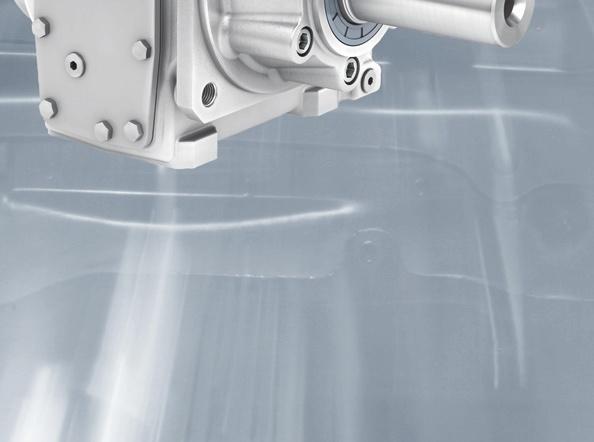
8 Introduction Orientation Overview 1 Electric-monorail geared motors SIMOGEAR electric-monorail geared motors form part of our SIMOGEAR product range. SIMOGEAR electric-monorail geared motors have been developed in cooperation with the conveyor technology and automation industries (particularly the automotive sector). The result of this development process is a finely scaled program of geared motors with high permissible wheel loads. State-of-the-art production technology and improved testing methods ensure the highest degree of quality and reliability. SIMOGEAR electric-monorail geared motors have been designed using high-efficiency bevel gearboxes. The gearboxes for light-load applications are two-stage bevel gearboxes. The drives for heavy-load applications are three-stage bevel gearboxes. BH.29 and BH.9 geared motors are suitable for use as an electric-monorail drive in accordance with VDI guideline 64. Further information about design in accordance with VDI guideline 64 can be found in chapter "Configuring guide" on page 2/4. Gearbox type Gearbox designation Maximum Transmission output torque ratio Maximum motor power Maximum radial force Flange Shaft Light-load applications T 2N i P 1 F R2 Nm - kw N mm mm BH FT95 25 x 5 BH FT95 25 x 5 0 x 50 Fig. 1/1 Bevel geared motor BH Heavy-load applications KHF x 60 5 x 70 KHF x 90 KHF x 110 Fig. 1/2 Bevel geared motor KHF Benefits High energy efficiency for a fast return on investment When developing SIMOGEAR geared motors, significant emphasis was placed on achieving the highest possible energy efficiency. Using the plug-on pinion principle in the first SIMOGEAR gearbox stage, higher transmission ratios are achieved when compared to gearboxes with slip-on pinion. Two-stage SIMOGEAR bevel geared motors B have a mechanical efficiency of 96 %. With a range of transmission ratios from i = 8.5 to 60.21, they have been specifically designed to address the requirements in conveyor technology. Together with the Siemens 1LE1 motors for efficiency classes IE2 (High Efficiency) and IE (Premium Efficiency), SIMOGEAR geared motors allow a high amount of energy to be saved and reduce the stress on our environment. Harmoniously coordinated modular system to provide the optimum solution for your particular drive task The fine size graduations of SIMOGEAR gearboxes provide you with the optimum drive for every application regarding gearbox type, rated output torque and transmission ratio. When developing SIMOGEAR geared motors, significant emphasis was placed on achieving well-balanced gearbox properties. With SIMOGEAR geared motors you can depend on harmonized and coordinated properties regarding: 7 Maximum output torque 7 Permissible radial force 7 Output shaft diameter 7 Bearing service life 7 Housing stiffness 7 Gearing reliability (fatigue endurable) 7 Shaft strength (fatigue endurable) 7 Smooth running The MODULOG modular principle for outstanding flexibility The motors used for the SIMOGEAR geared motors have a modular design using our well-proven MODULOG modular principle. At the heart of the system is a basic motor dimensioned for international line supply conditions with power ratings extending from 0.09 to 7.5 kw (2/4/6/8-pole). At the non-drive end (NDE), you have an individually configurable MODULOG modular system, e.g. for brakes, backstop, rotary pulse encoder, separately driven fan and canopy. 1/2 Siemens MD
9 Electric-monorail systems Electric-monorail systems (suspended monorail) are a modern and cost-effective transport system for handling internal material flows. Typical applications for these systems include the transport of light loads (such as components used in the assembly of domestic appliances) and the movement of heavy loads (vehicles in the automotive industry, for example). Electric-monorail systems are already well established in many industrial sectors: Automotive industry Domestic appliance industry Storage and distribution centers Passenger transport Food processing technology Thanks to electric-monorail systems, it is possible to utilize the "third dimension", i.e. the ceiling area. As a result, the floor area remains unobstructed so that many hazards associated with material transport can be avoided. They also offer a host of other advantages: Flexible routing Fast, flexible transport speed High availability; each vehicle has its own independent drive Low maintenance costs due to minimal wear Easy expansion of plant by addition of further trolleys High overall efficiency Introduction Orientation Electric-monorail systems comprise the following components: Electric-monorail geared motor with or without distributed inverter technology Controller Frequency inverter SIMOGEAR electric-monorail bevel geared motors are based on the modular system of SIMOGEAR geared motors. As a result, the motors can be equipped with a large number of options. A special feature of SIMOGEAR electric-monorail drives which essentially differentiates them from other products in the range is their mechanical clutch that releases the traction between the drive and the conveyor system. The mechanical clutch can be used to perform the following tasks: To commission the plant in the early stages before electrical power is available. In this case, the trolleys can be moved manually in the uncoupled state along the conveyor rails. To move or redirect the trolley manually in the event of a fault to prevent a collision with the next trolley. To move the trolley along steep upward or downward gradients, e.g. using a chain conveyor. SIEMENS electric-monorail systems are mainly characterized by the seamless integration of their components and a host of other advantages at product level. Further information about electric-monorail systems can be found at: 1 Plant control PROFINET/Ethernet Programming device SIMATIC S7-00 with visualization WinCC Flexible SDC Segment control SIMATIC S SIMATIC S Busbar terminal box Vehicle control Vehicle 1 Vehicle 2 Vehicle Busbar terminal box Vehicle n Communication EMS40S Communication EMS450S Communication EMS470S Communication EMS470S SIRIUS contactor/sirius RM1 SINAMICS V20 SIMOGEAR SIMOGEAR System concept - conveyor system with SIMATIC EMS 400 SIMOGEAR with SINAMICS G110M SINAMICS G120D SIMOGEAR G_D087_EN_0016 Fig. 1/ Conveyor technology system concept Siemens MD /

10 Introduction Orientation 1 Configuring Drive Technology Configurator (DT Configurator) within the CA 01 The Interactive Catalog CA 01 the offline Industry Mall of Siemens on DVD-ROM contains over products with approximately 5 million possible drive system product variants. The Drive Technology Configurator (DT Configurator) has been developed to facilitate selection of the correct geared motor and/or inverter from the wide spectrum of drives. It is integrated as a selection tool in Catalog CA 01. Description Interactive Catalog CA 01 on DVD-ROM including Drive Technology Configurator, English Article No. E86060-D4001-A510-D Drive Technology Configurator (DT Configurator) The Drive Technology (DT) Configurator supports you when configuring the optimum drive technology products for your application from gearboxes, motors, inverters as well as the associated options and components through to controllers, software licenses and connection systems. With or without detailed knowledge of products: Preselected product groups, targeted navigation through selection menus and direct product selection through entry of the article number support quick, efficient and convenient configuration. In addition to all this, comprehensive documentation comprising technical data sheets, 2D dimensional drawings/d CAD models, operating instructions, certificates, etc. can be selected in the DT Configurator. Immediate ordering is possible by simply transferring a parts list to the shopping cart of the Industry Mall. Online DT Configurator In addition, the DT Configurator can be used on the Internet without requiring any installation. The DT Configurator can be found in the Siemens Industry Mall at the following address: STARTER commissioning tool The STARTER commissioning tool (V4. SP and higher) simplifies the commissioning and maintenance of the SINAMICS G110M motor integrated frequency inverter. The operator guidance combined with comprehensive, userfriendly functions for the relevant drive solution allow you to commission the device quickly and easily. Additional information about the STARTER commissioning tool is available on the Internet at: SINAMICS Startdrive commissioning tool SINAMICS Startdrive is a tool for configuring, commissioning, and diagnosing the SINAMICS family of drives and is integrated into the TIA Portal. SINAMICS Startdrive can be used to implement drive tasks with the SINAMICS G110M (SINAMICS Startdrive V1 and higher), SINAMICS G120, SINAMICS G120C, SINAMICS G120D and SINAMICS G120P inverter series. The commissioning tool has been optimized with regard to user friendliness and consistent use of the TIA Portal benefits of a common working environment for PLC, HMI and drives. The SINAMICS Startdrive commissioning tool is available free on the Internet at: SIZER for Siemens Drives For the project engineering of SIMOGEAR geared motors operating on SINAMICS frequency inverters, the engineering tool "Sizer for Siemens Drives" should be used. This ensures that all the relevant aspects are taken into consideration (line voltage, type of DC link (regulated/unregulated), utilization of the motor in accordance with temperature class B or F, motor current for inverter operation in Y circuit or D circuit, calculation of the regenerative power, dimensioning of the braking resistor with reference to the entered cyclic operation, etc.) The SIZER for Siemens Drives engineering tool is available free on the Internet at: Fig. 1/4 DT Configurator Drive Technology Configurator for efficient drive configuration with the following functions Fast, efficient configuration of drive products and associated components gearboxes, motors, inverters, controllers, connection systems Configuration of drive systems for pump, fan and compressor applications from 1 kw to 2.6 MW Displayable documentation for configured products and components, such as - Data sheets in PDF or RTF format - 2D dimensional drawings/d CAD models in various formats - Terminal box drawings and terminal connection diagrams - Operating instructions - Certificates - Start-up calculation for SIMOTICS motors Support with retrofitting in conjunction with Spares On Web ( Ability to order products directly in the Siemens Industry Mall 1/4 Siemens MD
11 Overview The Article No. comprises a combination of digits and letters. To obtain a better overview, the Article No. is split up into three hyphenated blocks. Example: 2KJ804-11CE11-9HH1-Z N6C+K01+D11+L00+K07+K24+M55+K50 The first block (data positions 1 to 7) designates the gearbox type; the second (data positions 8 to 12) designates the output shaft and the motor type; and additional design characteristics are coded in the third block (data positions 1 to 16). Introduction Guidelines for selection and ordering Article No. code Ordering data Complete Article No. with a -Z suffix, and order code(s) or plain text. If a quotation has been requested, please specify the quotation number in addition to the Article No. When ordering a complete geared motor as a replacement unit, the serial number of the original geared motor must be specified. 1 Structure of the Article No. Position of the Article No Z SIMOGEAR geared motors 1st to 5th position: Digit, letter, letter, digit, digit Electric-monorail gearbox 2 K J 8 6th to 7th position: Digit, digit Gearbox size th position: Output shaft - Digit 9th to 10th position: Letter, letter Motor frame size 11th position: Induction motor LA 1 Digit Induction motor LE General Purpose (aluminum) 2 12th position: Motor with improved efficiency 1 Digit (Standard Efficiency IE1) Motor with high efficiency 2 (High Efficiency IE2) Motor with premium efficiency (Premium Efficiency IE) 1th position: Digit Frequency, voltage - 14th position: Foot-mounted design A Letter Housing flange design H Flange-mounted design F 15th to 16th position: Transmission ratio Letter, digit Special versions Coded Order code required - Z Non-coded Plain text required Siemens MD /5
12 Introduction Guidelines for selection and ordering Article No. code 1 Overview (continued) Ordering example An electric-monorail geared motor is required: Gearbox type, size BHZ9 Motor 0.7 kw, 4-pole with 50 Hz line frequency Output speed 7, transmission ratio i = Solid shaft V0 x 60 Mounting position M1 Output side A Terminal box position 1A HAN Q8 motor plug with 0.5 m cable This results in the following Article No. with order codes: Position of the Article No Z + Order codes Selection criteria Requirements Gearbox type Electric-monorail 2 K J bevel gearbox, 2-stage Gearbox size Size 9 2 K J Output shaft Solid shaft V0 x 60 2 K J Motor frame size Frame size 71; 2 K J C E 0.7 kw; 4-pole Motor type Induction motor LA 2 K J C E 1 Motor efficiency Standard Efficiency IE1 2 K J C E 1 1 Line voltage, frequency 400 V / 50 Hz 2 K J C E N6 C Mounting type Housing flange 2 K J C E H + N6 C Transmission ratio i = K J C E H H 1 + N6 C Mounting position M1, output side A 2 K J C E H H 1 - Z + N6 C Terminal box position 1A 2 K J C E H H 1 - Z + N6 C Motor plug HAN Q8 with 0.5 m cable 2 K J C E H H 1 - Z + N6 C + D11 + D11 + M5 5 + D11 + M K50 1/6 Siemens MD
13 Type designation of the gearboxes The type designation is a meaningful name for SIMOGEAR geared motors. Introduction Guidelines for selection and ordering Type designation It provides information about the fundamental design of the geared motor and about its main technical features. 1 Example of gearbox type designation: BH Z 9 Gearbox type Bevel gearbox, light load BH Bevel gearbox, heavy load KH Type Shaft Solid shaft - Mounting Foot-mounted design - Flange-mounted design F Housing flange design Z Connection Feather key / without feather key - Gearbox size Bevel gearbox BH 29 9 Bevel gearbox KH Type designation of the motors Example of motor type designation: LE 90 ZLR - 4 P MFW L 2/14 MN IA Definition of motor Motor type Three-phase motor Aluminum housing LA, LE Type Integral mounting - Motor frame size Specified acc. to EN Overall length Extended housing Z Overall length specified acc. to EN 5047 S, L, M Packet length / power value A... Z Number of poles 2-pole 2 4-pole 4 6-pole 6 Special features Efficiency class Different to IE2 or IE - IE2 (High Efficiency) E IE (Premium Efficiency) P SINAMICS G110M With SINAMICS G110M motor integrated frequency inverter M Ventilation Self ventilation - Forced ventilation F High inertia fan I Canopy With protective cover W Handwheel With handwheel D Brake Brake type DC brake L Rated braking L brakes torque Adjusted braking torque / Brake options Microswitch for monitoring brake release M Standard version N Enclosed brake G Manual brake release H Manual brake release with locking mechanism HA Encoder Incremental encoder IN Resolver IR Absolute encoder IA Prepared for encoder mounting IV Siemens MD /7
14 Introduction Guidelines for selection and ordering Notes on selection tables 1 Structure of the tables for geared motors In the selection tables you will find the most frequently used versions and combinations of geared motors sorted according to the motor power. Additional combinations can be selected with our DT Configurator. The power ratings and torques specified in the catalog refer to mounting position M1 and comparable types of construction where the input stage does not run completely immersed in oil. Further, standard equipment and standard lubrication of the geared motors as well as normal ambient conditions are assumed. The specified output speeds are guide values. You can calculate the rated input speed based on the rated motor speed and the transmission ratio. Please note that the actual output speed will depend on the motor load and the line supply conditions. P rated n 2 T 2 i F 1) R2 F R2 90 1) F R ) f B m Article No. Order code kw rpm Nm - N N N - kg (Article No. supplement below) Number of poles 0.12 Type designation BH.29-LA6ME KJ80-7 BC R1 (1) (2) () (4) (5) (6) (7) (8) (9) (10) (11) (1) Rated motor power at 50 Hz (2) Geared motor output speed () Geared motor output torque (4) Transmission ratio (5) Permissible radial force, optional force application angle (6) Permissible radial force, force application angle 90 (7) Permissible radial force, force application angle 270 (8) Service factor (9) Drive weight without any oil (10) Article No. (11) Order code for number of poles 1) Values apply to BH.9 for 0 x 50 solid shaft. For conversion for 25 x 5 solid shaft, see page 2/9. Structure of the tables for transmission ratios and torques In the selection tables for transmission ratios and torques, the gearboxes are sorted according to gearbox type and ratio. i n 2 T 2N F R2 F R2 90 F R2 270 J G R ex Motor frame size Article No. - rpm Nm N N N 10-4 kgm² Type designation BH /81 2KJ R1 (1) (2) () (4) (5) (6) (7) (8) (9) (10) (1) Transmission ratio (2) Geared motor output speed at a motor speed of rpm () Maximum gearbox output torque with service factor of f B = 1 (4) Permissible radial force, optional force application angle (5) Permissible radial force, force application angle 90 (6) Permissible radial force, force application angle 270 (7) Moment of inertia of the gearbox reduced to the input shaft (8) Ratio, number of teeth (9) Geometrically possible geared motor combination (10) Article No. 1/8 Siemens MD
15 Introduction Guidelines for selection and ordering Structure of the motor power tables Left-hand side Frame size Notes on selection tables Motor P rated n rated T rated I rated cos I St /I rated Article No. Order code 4/4 load /4 load Data position Number kw rpm Nm A - % % - 9th 10th 11th 12th of poles 4-pole, rpm at 50 Hz 80 LE80MD4E D C LE80MH4E D E (1) (2) () (4) (5) (6) (7) (8) (8) (9) (10) (10) (11) (12) (1) (1) Motor frame size (2) Motor designation () Rated power (4) Rated speed (5) Rated torque (6) Rated current (7) Power factor (8) Efficiency (9) Relative starting current (10) Article No. of the motor frame size (11) Article No. of the motor type (12) Article No. of the motor series (1) Order code for number of poles For different voltages, the starting, average acceleration and breakdown torque change acc. to a square law from their rated value. Right-hand side Frame size Motor T St /T rated T Bk /T rated T A /T rated L pfa L WA Z 0 J mot m mot Article No. Order code Data position Number db (A) db (A) 1/h 10-4 kgm² kg 9th 10th 11th 12th of poles 4-pole, rpm at 50 Hz 80 LE80MD4E D C LE80MH4E D E (1) (2) () (4) (5) (6) (7) (8) (9) (10) (11) (11) (12) (1) (14) (1) Motor frame size (2) Motor designation () Relative starting torque (4) Relative breakdown torque (5) Relative average acceleration torque (6) Measuring surface sound pressure level (7) Sound power level (8) No-load switching frequency (9) Moment of inertia (10) Weight (without end shield at DE) (11) Article No. of the motor frame size (12) Article No. of the motor type (1) Article No. of the motor series (14) Order code for number of poles Siemens MD /9
16 4 Siemens AG 2017 Introduction Guidelines for selection and ordering Notes on dimensional drawings 1 Overview Standards DIN/ISO DIN 74 ISO 281, ISO 76 DIN 7190 DIN 6892 DIN 991 Output shafts Bearings Interference fits Parallel key connection Bevel gear toothing Designs according to AGMA available on request. Shaft heights DIN 747 shaft heights for machines Shaft height Tolerance mm mm Note: For foot-mounted gearboxes, the mounted motor can extend below the mounting surface of the gearbox. Shaft extensions DIN cylindrical shaft extensions Flanges Centering edge tolerance: Outer flange diameter mm Tolerance mm ISO j6 ISO h6 Vent valves The gearboxes are shown in the dimensional drawings with screw plugs. If venting is required, then depending on the type of construction, an activated vent valve is installed. The contour dimension can change slightly as a result. BHZ ,5 4x90 45 Ø , ,5 M8x14 29,6 kb k LBL LB ØAC 9 Ø , , Ø7,9 Ø74 j6 Diameter tolerance: Diameter Tolerance mm mm 50 ISO k6 > 50 ISO m6 Ø AD DR M10x Ø25 k6 Centering holes according to DIN 2, form DR: Diameter Thread size mm - > 24 0 M10 > 0 8 M12 > 8 50 M16 > M20 Fig. 1/5 Example, dimensional drawings Ø25 k6 DR M10x22 4 Ø25 k6 Undercut according to DIN 509: Diameter Undercut acc. to DIN 509 Suggested construction, minimum hollow on mating piece mm mm > E1.0x x 45 > E1.2x x 45 > E1.6x x 45 > E2.5x x 45 1/10 Siemens MD
17 Overview The following certificates are available for SIMOGEAR geared motors. You can select these individually, or combine them freely into a multi-certificate. Specifications Introduction General technical specifications Geared motors for use worldwide 1 Country/economic area Marking Legal/normative requirements Examples Europe/EU Low Voltage Directive (LVD) 2006/95/EC Eco-design Directive 2009/125/EC EU Regulation (EC) No. 640/2009 to implement the eco-design directive and amending regulation (EU) No. 4/2014 USA MG1-12 NEMA MG1-12 National standard UL 1004 Standard of the Underwriters Laboratories Inc. (testing and certification body) CC02 A EISA Energy Independence Security Act Canada CSA-C22.2 No. 100 Standard of the Canadian Standards Association EER Energy Efficiency Regulations China CCC China Compulsory Certification CEL China Energy Label Based on the national standard GB ECL Energy Conservation Law of PRC Russian Federation EAC Eurasian Conformity Belarus Kazakhstan Siemens MD /11
18 Introduction General technical specifications Geared motors for use worldwide 1 Without CE marking for export For geared motors to be exported outside the European Economic Area, the order option "without CE marking for export" is available. The CE marking is not displayed on the rating plate of these motors. These geared motors may only be exported to countries outside the European Economic Area which do not require the CE marking. Order code: Without CE marking Motors for the North American market Motors in frame sizes 6 to 12 are available in designs which meet the UL-R and CSA standards. Order code: Design in accordance with UL-R and CSA N68 N8 Note: In the USA, a distinction is made between the rated voltage of the supply system and the rated voltage of the motor. See the table below for the assignment: Country Rated voltage of the Rated voltage of the motor supply system USA 208 V 200 V 240 V 20 V 480 V 460 V Canada 600 V 575 V UL-R Underwriters Laboratories Inc. The motors are listed for up to 600 V by Underwriters Laboratories Inc. ("Recognition Mark" = R/C). Motor voltages up to 600 V are certified according to UL. "UL Recognition Mark" is included on the rating plate of the motor. In addition, the motor is designed to meet the NEMA MG1-12 electrical standard and includes the following data on the rating plate: Rated voltage(s) Nominal efficiency Design letter Code letter CONT NEMA MG1-12. Externally or internally mounted components such as: Motor protection Heating element Forced ventilation Brake Encoder Plug connection are UL-R/C, CSA, or C-US listed or used by manufacturers in accordance with regulations. UL-R/C cable glands must be used for the cable entry. CSA Canadian Standard Association The motors are approved for up to 690 V in accordance with the "Canadian Standard Association" (CSA). Externally or internally mounted components which are used are listed by CSA or are used by manufacturers in accordance with regulations. The CSA mark and the rated voltage are stamped on the rating plate. When energy-saving motors are ordered, they also have the "CSA-E mark" on the rating plate. Motors for the Chinese market CCC-certified motors, frame sizes 6 to 90, are available for export to China. The "China Energy Label" required for import into China is available for motors in frame sizes from 80 to 12. The motors are marked according to the requirements with CCC, CEL or both specifications. Order code: Design for the Chinese market N67 CCC China Compulsory Certification "Small power motors" which are exported to China must be certified up to a rated power of: 2-pole: 2.2 kw 4-pole: 1.1 kw 6-pole: 0.75 kw 8-pole: 0.55 kw Motors requiring certification are certified by CQC (China Quality Certification Center). When ordered, the "CCC (Safety Mark)" logo is stamped on the rating plate and packaging. Note: Chinese customs checks the need for certification of imported products by means of the commodity code. The following do not need to be certified: Motors imported to China which have already been installed in a machine Repair parts CEL China Energy Label China introduced mandatory energy efficiency labeling for electric motors in June From September 1, 2008, and until the transition phase expires, the affected electric motors may only be imported into China and sold in the country with a valid "China Energy Label". The motor must be labeled with the "China Energy Label" sticker, which states the efficiency class. In addition to the Energy Label (dimensions 80 x 54 mm), the efficiency is also stamped on the rating plate. 2-pole, 4-pole and 6-pole motors with a line frequency of 50 Hz and a rated voltage of up to V must be appropriately marked. Efficiency classes 2 and apply here to motors with rated powers from 0.75 to 75 kw. Motors for the Eurasian market SIMOGEAR geared motors are certified for the Eurasian Economic Area. In the Russia, Kasachstan and Belarus customs union, new technical regulations and uniform conformity requirements (EAC) have been introduced. These replace the previous GOST-R certificates which thus lose their validity. The certificate is mandatory for export and is required by the customs authorities. The EAC certificate is valid for all geared motors. For gearboxes with adapters, the EAC certificate is not necessary because the EAC certificate only refers to the motor. Order code: Design in accordance with EAC N0 1/12 Siemens MD

19 Configuring guide Siemens AG /2 Determining the drive data 2/2 Overview 2/2 Checklist 2/4 Design in accordance with VDI 64 2/6 Configuring a gearbox 2/6 Service factor 2/6 Determining the required service factor 2/6 Determining the load classification 2/6 Mass acceleration factor 2/7 Required torque 2/7 Input speed 2/8 Shaft load and bearing service life 2/8 Available radial force 2/9 Permissible radial force 2/9 Radial force conversion for out of center force application point 2/9 Definition of the force application point 2/10 Configuring a three-phase motor 2/10 Determining the duty type 2/11 Switching frequency 2/12 Additional moments of inertia 2/12 Line feeder cables 2/12 Undervoltage 2/12 Motor protection 2/12 Current-dependent protective devices 2/12 Temperature-dependent protective devices 2/12 Coolant temperature and installation altitude 2/1 Degrees of protection 2/1 Cooling and ventilation 2/1 Forced ventilation 2/14 Configuring a brake 2/14 Overview 2/14 Determining the braking torque 2/14 Braking torques as a function of the speed and permissible speed limits 2/14 Braking energy per braking operation 2/14 Service life of the brake lining 2/14 Brake service life 2/15 Brake control 2/15 Definition of switching times (VDI 2241) 2/15 Fast brake application 2/15 Fast brake release 2/16 Brake switching time 2/16 Braking distance and positioning accuracy 2/16 Cyclic duration factor 2/17 Configuring a motor for inverter operation 2/17 Operation of geared motors on a frequency inverter 2/17 Motor characteristic 2/17 Utilization in accordance with temperature class F 2/18 Permissible voltage stress 2/18 Bearing currents 2/18 Mechanical stress, grease service life Siemens MD
20 Configuring guide Determining the drive data 2 Overview SIMOGEAR geared motors permit individual solutions to be created for a wide range of drive applications. In order to select the correct drive, specific data for the application must initially be known or determined. For drives operating under special conditions, e.g. frequent reversing, short-time or intermittent duty, abnormal temperatures, reversal braking, extreme cantilever forces at the gearbox output shaft, etc., please consult your Siemens contact person. Checklist You will find additional information on our website at Basic version VDI guideline 64: yes no Power rating: Number of starts/hour: s/h Line voltage: V Line frequency: 50 Hz 60 Hz 87 Hz Maximum frequency: Hz Brief description of the system: Environmental conditions Installation altitude: m Outdoor operation Increased environmental stress Air humidity: % Normal environmental stress Aggressive environmental stress Temperature: from to C General Trolley Type of trolley: Trolley type 1 Trolley type 2: Trolley type Front running wheel, driven Rear running wheel, driven Dimensions: H mm (Vertical distance between running wheel axis and center of gravity) L1 mm (Distance between running wheels) L2 mm (Horizontal distance between running wheel and center of gravity) L mm (Distance between swivel joints) S mm (Center of gravity) Track Max. upward gradient: Height difference upward gradient: mm Max. downward gradient: Height difference downward gradient: mm Min. curve radius: mm Design data Weight of trolley: kg Weight of load: kg Wheel load (of driving wheel on rail): Distance from shaft shoulder to force application point x Running wheel diameter: mm Running wheel material: Polyurethane Cyclic duration factor: % N mm Other Deceleration: m/sec 2 Upward gradient m/sec 2 Downward gradient m/sec 2 Acceleration: m/sec 2 Upward gradient m/sec 2 Downward gradient m/sec 2 Travel velocity: min. m/sec max. m/sec Upward/downward gradient m/sec 2/2 Siemens MD
21 Configuring guide Determining the drive data Checklist (continued) Gearbox Technical specifications Transmission ratio: Output torque: Nm Output speed: rpm Mounting and mounting position Mounting position: M1 M2 M M4 M5 M6 Terminal box position: Mounting type: Flange Foot Shafts Design: Solid shaft with feather key Solid shaft without feather key Shaft dimensions: (d x l) x mm 2 Other options: Motor Electrical design Motor protection: PTC thermistor Winding thermostat Temperature sensor KTY x resistance thermometer PT100 Mechanical design Degree of protection: IP55 IP65 Cooling & ventilation: Self ventilation Forced ventilation High inertia fan Motor plugs: HAN 10E HAN Q8 HAN Q8 with cable Cable length: m HAN Q12 Others Mounted components Brake: Brake Control voltage: V Disconnection: DC/AC Manual release Perm. braking distance mm Encoder: Incremental encoder Absolute encoder Resolver Prepared for encoder mounting Frequency inverter: Other options: General options Surface treatment Surface protection: C1 C2 C C4 C5 unpainted C2 primed C4 primed RAL color: Other options: Siemens MD /
22 Configuring guide Determining the drive data 2 Design in accordance with VDI 64 The VDI guideline 64 is a set of minimum requirements defined by the VDI-Gesellschaft Fördertechnik Materialfluss Logistik (Society for Materials Handling, Materials Flow and Logistics Engineering) for the optimum, harmonized selection of drive systems for electric-monorail geared motors. The order option as per VDI 64 is provided as a selection guide. The only available drives and options are those which conform to the permissible installation dimensions specified by VDI 64. Electric-monorail geared motors in accordance with VDI 64: Order code: Design in accordance with VDI 64 K42 The permitted selection options can be found in the following tables. Geared motor Motor frame size LA6 LA71 LE80 LE90 LE100 LE112 LE12 Gearbox type BH BH KHF KHF KHF Rated motor power 0.12 kw 4- or 6-pole kw 2- or 4-pole 6-pole kw 2-pole 4- or 6-pole kw - 2- or 4-pole kw - 2- or 4-pole kw kw kw kw kw Required selection in accordance with VDI guideline 64: Description of option Motor frame size Order code Technical information LA6 LA71 LE80 LE90 LE100 LE112 LE12 page Terminal box type Terminal box gk page 6/14 Motor plug HAN Q8 motor plug with 0.5 m to 5 m cable Available options in accordance with VDI guideline 64: K50... K55 page 6/21 Option Motor frame size Order code Technical information LA6 LA71 LE80 LE90 LE100 LE112 LE12 page Mechanical design Cooling and ventilation Standard fan page 6/9 Metal fan M21 page 6/9 High inertia fan M22 page 6/9 Forced ventilation M2 page 6/10 Terminal box type Standard terminal box Cable entry NPT M45 page 6/14 Motor plug HAN Q8 motor plug with 0.5 m to 5 m cable K50... K55 page 6/21 HAN 10E motor plug N00, N01, N04, N06 page 6/16 HAK 4/4 motor plug N08... N11, N19 page 6/17 HAN Q8 motor plug EMC N12 page 6/19 HAN Q12 motor plug EMC N1 page 6/2 2/4 Siemens MD
23 Configuring guide Determining the drive data Design in accordance with VDI 64 (continued) Available options in accordance with VDI guideline 64: Option Motor frame size Order code Technical information LA6 LA71 LE80 LE90 LE100 LE112 LE12 page Mounted components Brakes L B00... B0, B57 page 6/24 L B04... B09 page 6/24 L16... L B10... B2, B66, B67 Manual brake release page 6/24 Manual brake release C02 page 6/28 Manual brake release with locking C0 page 6/28 mechanism DC voltages 24 V DC ± 10 % C66 page 6/25 10 V DC ± 10 % C52 page 6/ V DC ± 10 % C5 page 6/ V DC ± 10 % C64 page 6/25 AC voltages page 6/25 Function rectifier C59, C60 page 6/26 Brake cable protection C80 page 6/26 Encoder Q50... Q94 page 6/7... page 6/50 SINAMICS G110M U01... U2 page 6/52 distributed frequency inverter International standards CE Design in accordance with EAC N0 page 1/12 Design in accordance with UL/CSA N8 page 1/12 (incl. NEMA) Design for the Chinese market 1) N67 page 1/12 Without CE marking N68 page 1/12 General ATEX design K70, K80... K82-1) Designs not possible for motor frame size 71 with 0.55 kw power rating. 2 Siemens MD /5
24 Configuring guide Configuring a gearbox 2 Service factor Determining the required service factor The operating conditions are crucial in determining the service factor and for selecting the geared motor. These are taken into account by the service factor f Btot. In standard operation, i.e. with a uniform load provided by the driven machine, small masses to be accelerated, and a low switching frequency, the service factor of f Btot = 1 can be selected. For different operating conditions, the service sector can be taken from the tables. When the motor power and the gearbox output speed are known, a gearbox type is selected with a service factor that meets the following condition: f Btot = f B1 f B The gearbox size or rated gearbox torque and the resulting service factor are not standardized and depend on the manufacturer. Determining the load classification The service factor of the driven machine f Btot is determined from the load classification, switching frequency, and operating period per day. The operating conditions can vary greatly. To determine the service factor, empirical values can be derived from the configuration of other similar applications. The driven machines can be assigned to three load groups according to their load classification. These groups are assessed based on their mass acceleration factor m AF. Load groups of driven machines Load classification I Almost shockfree II Moderate shock loads III Heavy shock loads Service factor f B1 Fig. 2/ Mass acceleration factor Operating period per day 24 h 16 h 8 h Service factor f B1 Driven machine (examples) Electric generators, belt conveyors, apron conveyors, screw conveyors, lightweight elevators, electric hoists, machine tool feed drives, turbo blowers, centrifugal compressors, mixers and agitators when mixing materials with uniform density Machine tool main drives, heavy elevators, slewing gear, cranes, shaft ventilators, mixers and agitators when mixing materials with non-uniform densities, reciprocating pumps with multiple cylinders, metering pumps Punching presses, shears, rubber kneaders, machinery used in rolling mills and the iron and steel industry, mechanical shovels, heavy centrifuges, heavyweight metering pumps, rotary drilling rigs, briquetting presses, pug mills Load classification III Load classification II Load classification I Number of starting operations per hour 1250 G_D087_EN_ Note: When selecting and dimensioning drives with the following special application conditions, please contact Siemens. Frequent reversing Short-time and intermittent operation Abnormal temperatures Reversal braking Extreme and/or circulating radial forces at the gearbox output shaft Fluctuating loads Mass acceleration factor The mass acceleration factor m AF is calculated as follows: J x m AF = J mot + J B + J Z All external moments of inertia are moments of inertia of the driven machine and the gearbox, which are to be reduced to the motor speed. The calculation is made using the following formula: n J X J J 2 = = n 1 i 2 In most cases the relatively insignificant moment of inertia of the gearbox can be ignored. The mass acceleration factor m AF is calculated as follows with reference to the gearbox and the adapter: J x + J G + J AD m AF = J mot + J B + J Z Code Description Unit i Transmission ratio - J 2 Moment of inertia of the load referred kgm² to the output speed of the gearbox J AD Moment of inertia of the adapter referred kgm² to the input speed J B Moment of inertia of the brake kgm² J G Moment of inertia of the gearbox based on kgm² the input speed J mot Moment of inertia of the motor kgm² J X Moment of inertia of the load referred kgm² to the input speed J Z Additional moment of inertia of kgm² a high inertia fan m AF Mass acceleration factor - n 1 Input speed of the gearbox rpm n 2 Output speed of the gearbox rpm 2/6 Siemens MD
25 Configuring guide Configuring a gearbox Required torque Once the load situation (drive data) and the service factor have been clarified, then the required output torque can be determined. P mot 9550 P mot 9550 T 2 = = i n 1 n 2 Code Description Unit Gearbox efficiency % i Transmission ratio - n 1 Input speed of the gearbox rpm n 2 Output speed of the gearbox rpm P mot Motor power kw T 2 Required output torque of the driven machine Nm 2 Input speed For an identical power and output speed, in the selection tables 4-pole geared motors have priority over 6-pole motors. As result of the very wide range of transmission ratios of SIMOGEAR gearboxes, it is hardly necessary to use motors with other pole numbers. In addition to good availability worldwide, 4-pole motors generally offer the optimum solution regarding price, length, noise level and service life. Siemens MD /7
26 Configuring guide Configuring a gearbox 2 Shaft load and bearing service life Available radial force The total available radial force comprises the force due to weight on the running wheel and the tangential force exerted by the torque. The weight distribution depends on the relevant trolley type and on the number of drives and running wheels. Forces are also exerted as a result of weight transfer during startup, braking and ascending travel. These forces must be taken into account in the available radial force calculation. Your Siemens contact person will be pleased to provide configuring advice. In order to dimension the drive, we will need the completed checklist on page 2/2. Variables for defining shaft load and bearing service life Code Description Unit H Vertical distance between running axis and mm center of gravity L1 Distance between running wheels mm L2 Horizontal distance between running wheel mm and center of gravity L Distance between swivel joints mm S Center of gravity mm Trolley type 1 H S G_D087_XX_00299 Fig. 2/2 Trolley type 1: 1 running wheel, one wheel is driven Trolley type 2 L1 H L2 S G_D087_XX_0000 Fig. 2/ Trolley type 2: 2 running wheels, one wheel at the front or rear is driven Trolley type L1 L H L2 S G_D087_XX_0001 Fig. 2/4 Trolley type : 4 running wheels, 2 wheels are driven 2/8 Siemens MD
27 Configuring guide Configuring a gearbox Shaft load and bearing service life Permissible radial force The selection tables specify the permissible radial force F R2. The table values refer to the force application point x, see table "Gearbox constants for calculating the radial force". Note: For BH.9 with 25 x 5 solid shaft, the permissible radial force F x must always be calculated using the conversion below (even when x = 18 mm), because the table values apply to a 0 x 50 solid shaft. Radial force conversion for force application at distance other than x When the distance x to the shaft shoulder is other than the value stated in the table, use the following formulas to convert the permissible radial force. The lowest value of F xperm1 (bearing service life), F xperm2 (strength) and F Rmax is the permissible radial force F x. The calculation is applicable without axial force. Permissible radial force according to the bearing service life y F xperm1 = F R z+ x1 Permissible radial force according to the shaft strength a F xperm2 = b+ x1 Permissible radial force for force application at distance other than x F x F xperm1 ; F xperm2 ; F R2max Condition: Available radial force permissible radial force Variables for defining shaft load and bearing service life Code Description Unit Force application angle a, b, d, l, y, z Gearbox constants Nmm / mm d 0 Average diameter of the mounted mm transmission element F G Force due to weight N F R2 Permissible radial force (from power table) N F R2max Maximum permissible radial force according N to table "Gearbox constants for calculating the radial force" F Ravail Available radial force N F x Permissible radial force from out of center N force application point F xperm1 Permissible radial force, limited by the N bearing service life, at a distance of x from the shaft shoulder F xperm2 Permissible radial force, limited by the shaft N strength, at a distance of x from the shaft shoulder RWC Running wheel center - x Distance from the shaft shoulder up to the force application point at running wheel center for F R2 according to table "Gearbox constants for calculating the radial force" mm x1 Distance from the shaft shoulder up to the force application point at running wheel center for F x mm 2 Definition of the force application point α 90 View Z F R2 F X Z Ød G_D087_EN_0017 F R2 270 x RWC F R2 F X F Fig. 2/5 Force application point Gearbox constants for calculating the radial force Gearbox size Constants y z a b d l T 2 F R2max Force application x mm mm Nmm mm mm mm Nm N mm Light-load applications BH BH BH Heavy-load applications KH KH KH KH x x1 x Siemens MD /9
28 Configuring guide Configuring a three-phase motor Determining the duty type The power ratings for continuous duty with constant load (duty type S1) are listed in the power tables. The motor power ratings can be converted to the lower duty cycle using the corresponding k DC factors for S1, S2, and S duty types. 2 P DC = P rated k DC Code Description Unit P DC Power for the new duty cycle kw P rated Rated motor power kw k DC Factor for increased power - For increased power, you should note that the breakdown torque ratio must not fall below 1.6. This same regulation applies when differentiating between the following groups of duty types. Duty types according to EN (IEC ) Duty type Description Information required Factor for increased power S1 S2 S S4 S10 Continuous duty Cyclic duration factor = 100 % Constant load for a brief time, e.g. S2-0 min Intermittent periodic duty, where starting has no significant influence (cyclic operation), e.g. S - 40 % Intermittent periodic duty with the influence of starting k DC Load duration 60 min min min 1.40 Cyclic duration factor in % (referred to 10 min) 60 % % % % 1.40 Cyclic duration factor in % (referred to 10 min), starts per On request - hour, load torque and moment of inertia The duty type and motor power can be determined if the number of starting operations per hour, starting time, load duration, type of braking, braking time, idle time, cycle time, standstill time, and required power are specified. 2/10 Siemens MD
29 Configuring guide Configuring a three-phase motor Switching frequency A higher switching frequency means that the motor winding will be subject to a thermal load. The permissible switching frequency Z perm has to be determined for different operating cases. This value is influenced by the corresponding load torque, the additional moment of inertia, the power requirement, and the cyclic duration factor. These can be evaluated using the factors k M, k FI and k P. For 60 Hz operation, the calculated permissible switching frequency Z perm must be reduced by 25 %. See the technical specifications for brakes in chapter 6 for the permissible switching frequency for operation with function rectifiers. k M G_M015_EN_00040c 2 The permissible no-load switching frequency Z A for motors with brake L must be obtained from table "No-load switching frequency for brakes L" on page 6/5. Z perm = Z A k M k FI k P The permissible no-load switching frequency Z 0 for motors without brakes must be obtained from the Selection and ordering data page 4/6. Z perm = Z 0 k M k FI k P Code Description Unit DC Cyclic duration factor % J mot Moment of inertia of motor and brake kgm 2 J Z Additional moment of inertia of the high inertia kgm 2 fan J X Moment of inertia of the load, reduced to kgm 2 motor shaft J add Additional moment of inertia, reduced to kgm 2 motor shaft k FI Factor for taking into account the additional moment of inertia - k M Factor for taking into account the load torque - while accelerating k P Factor for taking into account the required - power and duty cycle P S Actual steady-state motor power kw P rated Rated motor power kw T A Acceleration torque of the motor Nm T rated Rated motor torque Nm T x Load torque, reduced to motor shaft Nm t R Duty cycle (decimal) Z A No-load switching frequency, motor with 1/h brake Z 0 No-load switching frequency, motor without 1/h brake Z perm Permissible switching frequency 1/h Fig. 2/6 Fig. 2/7 0.1 k M = 1 J add = J x + J z 0 0 T X T A Torque when accelerating k 0.8 FI Additional moment of inertia k P T X T A J add J mot J mot k Fl = Jmot J add P 1 / P rated = G_M015_EN_00041a G_M015_EN_ DC [%] Fig. 2/8 Power requirement and duty cycle k P = t R (1 - (P S / P rated ) 2 ) (1 - t R ) t R Siemens MD /11
30 Configuring guide Configuring a three-phase motor 2 Additional moments of inertia Coolant temperature and installation altitude The motor moment of inertia with standard fan is specified in the The rated power specified in the selection tables in chapter 4 is motor selection lists. The higher moment of inertia should be valid for a coolant temperature of +40 C and an installation altitude of m above sea level. used for metal or high-inertia fans. This is also valid for mounted brakes, backstops and encoder systems. Please contact Siemens for higher coolant temperatures. Line feeder cables The table with correction factors provides a rough idea of the derating required if conditions are different. Line feeder cables must be adequately dimensioned. The number of required parallel (if applicable) feeder cables is determined by the maximum connectable conductor cross-section, the type of cable, the cable installation, the ambient temperature and the permissible current. In Germany, DIN VDE 0298 must be applied when dimensioning cables. Undervoltage For an undervoltage condition as a result of weak line supplies, catalog values such as motor power, torque and speed are not reached. This is especially important when considering motor starting. Motor protection A distinction is made between current-dependent and temperature-dependent protective devices for motors. Current-dependent protective devices Fuses are only used to protect line cables in the event of a short-circuit. They are not suitable for protecting the motor against overload. The motors are usually protected by thermally delayed overload protective devices (circuit breakers for motor protection or overload relays). This protection is current-dependent and is particularly effective in the case of a locked rotor. For normal operation with short starting operations, starting currents that are not excessive and for low numbers of starting operations, motor circuit breakers provide adequate protection. Motor circuit breakers are not suitable for heavy duty starting or high numbers of starting operations. Differences in the thermal time constants for the protective devices and the motor results in unnecessary early tripping when the circuit breaker is set to the rated current. Temperature-dependent protective devices Temperature-dependent protective devices are integrated in the motor winding and can be implemented as temperature sensors and temperature switches. The number of temperature-dependent protective devices depends on the number of windings and their function. The alarm is normally set to 10 K below the switch-off temperature. The rated response temperatures of the protective devices depend on the thermal class of the motors. In order to achieve full thermal protection, it is necessary to combine a thermally delayed overcurrent release and a PTC thermistor. This results in a permissible motor power of: P perm = P rated k HT Code Description Unit P perm Permissible motor power kw P rated Rated motor power kw k HT Factor for abnormal coolant temperature and - installation altitude Factor k HT for different installation altitude and coolant temperature Installation Coolant temperature alti- tude IA CT m < +0 C C +45 C +50 C +55 C +60 C /12 Siemens MD
31 Configuring guide Configuring a three-phase motor Degrees of protection Cooling and ventilation The motors are supplied in IP55 to standard IEC They can be installed in dusty or humid environments. The motors are suitable for operation in tropical climates. Guide value below 60 % relative air humidity for a coolant temperature of +40 C. Other requirements on request. First Brief description digit 4 The motor is protected against solid objects larger than 1 mm. 5 The motor is protected against dust. 6 The machine is dust-tight. Second digit Brief description 4 The motor is protected against water splashed from all sides. 5 The motor is protected against strong jets of water. 6 The motor is protected against "heavy seas" or powerful jets of water. 7 The motor is protected against immersion. 8 The motor is protected against long periods of immersion under pressure. When the geared motor is mounted and the air intake is restricted, you must ensure that a minimum clearance is maintained between the fan cover and the wall and that the cooling air is not immediately drawn in again. Further, it must be guaranteed that the cooling air flow to the gearbox is not obstructed. As a consequence, the gearbox operating temperature can be further reduced. Forced ventilation The use of a separately driven fan is recommended to increase motor utilization at low speeds and to limit noise generation at speeds significantly higher than the synchronous speed. Both are mainly used in conjunction with inverter operation. Typical areas of application for forced ventilation: High number of starting operations Inverter drives with a control range > 1:20 Inverter drives with rated torque at low speeds Inverter drive with high motor speeds Noise reduction At high speeds 2 The first digit of the degree of protection indicates the degree to which an enclosure provides protection against contact and the ingress of foreign bodies. The second digit indicates the protection that an enclosure offers regarding the ingress of water. Increased corrosion protection as well as additional protective measures for the winding (protection against moisture and acid, corrosion protection in the motor) can support the selected degree of protection. The degree of protection only refers to the motor. When selecting higher degrees of protection, the equipping on the gearbox side should be taken into account (seals, vents). Siemens MD /1
32 Configuring guide Configuring a brake 2 Overview The brakes can be used as working brakes or holding brakes. Braking torques as a function of the speed and permissible speed limits A holding brake is suitable for holding masses and loads at a The braking torque available decreases with increasing motor fixed position. A working brake is also capable of decelerating speed. masses and loads. The maximum permissible speeds from which emergency stops The brakes are designed as fail-safe spring-operated brakes. can be made are listed in the table on page 6/2. These speeds When the brake is mounted, it increases the length of the motor. should be considered as guide values and must be checked for The dimensions are shown in the dimensional drawings. the specific operating conditions. The spring-operated disk brakes are suitable for a standard ambient temperature range of -20 to +40 C. The maximum permissible friction energy depends on the Variables switching frequency and is shown for individual brakes in the diagram Permissible operating energy, page 6/2. Increased Code Description Unit wear can be expected when the brakes are used for emergency f br Braking torque correction factor - stops. J AD Moment of inertia of the adapter kgm² J G Moment of inertia of the gearbox kgm² J mot Moment of inertia of the motor kgm 2 Braking energy per braking operation kgm² J X Moment of inertia of the load referred to the motor shaft J Z Additional moment of inertia of a high inertia fan kgm 2 k Factor for taking into account operating - conditions L n Service life of the brake lining until readjustment h L nmax Service life of the brake lining until replacement h n br Braking speed rpm Efficiency % Q perm Permissible operating energy J s br Braking distance m t 1 Application time of the brake ms t br Braking time s T br Rated braking torque Nm T x Load torque Nm v Travel velocity m/s W Friction energy per braking operation J W tot Friction energy until the brake lining is replaced MJ W V Friction energy until the brake is readjusted MJ Z Switching frequency 1/h The braking energy W per braking operation comprises the energy of the moments of inertia to be braked and the energy which must be applied in order to brake against a load torque: T x is positive if the load torque is working against the braking torque (horizontal motion, upward vertical motion). T x is negative if it supports the brake (downward vertical motion). The permissible operating energy Q perm must be checked against the relevant switching frequency using the diagram Permissible operating energy, page 6/2. This is of particular importance for emergency-stop circuits. 2 T br J G + J AD + J mot + J z + J x n br W = T br T x Service life of the brake lining The service life of the brake lining L n until the air gap has to be readjusted depends on various factors. The main influencing factors include the masses to be braked, the motor speed, the switching frequency, and, therefore, the temperature at the friction surfaces. Determining the braking torque The braking torque must be selected in accordance with the particular drive application. The following criteria are decisive when it comes to making the selection: Static safety Required braking time Permissible brake delay Possible braking distance Brake service life Brake wear The braking torque is determined using the safety factor k, which can be selected in the range from 1.0 to 2.5. As a general rule of thumb, the factor for horizontal motion is approx. 1.0 to 1.5 and for vertical motion approx. 2.0 to 2.5. However, the precise braking torque depends to a large extent on the particular Service life of the brake lining until readjustment operating conditions. W V The rated braking torque is referred to a speed of n = 100 rpm L n = W Z and decreases with increasing motor speed. When calculating the braking torque, this is taken into account using the correction Service life of the brake lining until replacement factor f br. This means that the rated braking torque is applicable W for most braking operations for inverter operation. tot L nmax = W Z For line operation, braking is directly from the motor speed. In addition, for vertical conveyors, the increased speed when moving downwards must be taken into account. T br T x k f br W Q perm This means it is not possible to specify a value for the friction energy until readjustment that is valid for all operating conditions. However, a wear calculation can be made according to the friction energy, so that the service life can be defined in normal operation. The brake lining is subject to wear as a result of friction. As a consequence, the air gap increases and the brake application time lengthens. The air gap can be readjusted. The friction lining should be replaced after a certain number of readjustments. 2/14 Siemens MD
33 Configuring guide Configuring a brake Brake control Definition of switching times (VDI 2241) Excitation Characteristic torque 0.9 M Fig. 2/9 Brake switching times Switching times: t 1 Application time of the brake t 2 Disconnection time t Slipping time t 11 Response time t 12 Rise time t t 11 t 12 t 2 t 1 OFF Fast brake application Disconnection on the AC side If the brake is disconnected from the line supply, the brake is applied. With AC brake voltages, the brake application time is extended as a result of the inductance of the solenoid (disconnection on the AC side). This results in a considerable delay before the brake is mechanically applied. In order to achieve short brake application times, the circuit must also be disconnected on the DC side. Rectifier for disconnection on the DC side Electromagnetically released spring-operated disk brakes can be disconnected on the AC side and the DC side. Disconnection on the DC side means that the inductance and thus the magnetic field in the brake solenoid are reduced very quickly. For disconnection on the DC side, a wire jumper can be removed from the rectifier and replaced by the contacts of an external switch. This enables significantly shorter application times to be achieved than those achieved for disconnection on the AC side. ON 0.1 M Time Time G_D087_EN_00047a Function rectifiers for fast brake application If function rectifiers are used for fast brake application, then there is no need for an external switch and therefore less wiring is required. Disconnection on the DC side using current sensing One option of disconnecting on the DC side is to sense the motor current. If the motor current falls below the rectifier's sensor current when disconnected from the three-phase line supply, the brake solenoid is disconnected from the DC voltage electronically without any contacts. Used in conjunction with disconnection on the DC side by means of current sensing, rectifiers are generally suitable for being connected in parallel with the motor connection, even in applications involving moving loads or large moments of inertia. Brakes controlled in this way are completely wired to the motor terminal board. Inverter operation is not permissible. Disconnection on the DC side using voltage sensing Another option of disconnecting on the DC side is by sensing the rectifier supply voltage. An integrated switching transistor switches off the load if the input voltage falls below a specified switching threshold. Used in conjunction with disconnection on the DC side using voltage sensing, rectifiers are generally suitable for operation with separate AC-side brake control using an additional switching contact. Connection in parallel with the motor connection is also possible, but it is not recommended, as the rectifier disconnection response will be impaired by the influence of the motor winding. In addition, many applications involve driving loads or large moments of inertia. This can cause the no-load voltage generated when the motor coasts down to considerably delay brake application if the switching threshold for voltage sensing is not fallen below. If connection in parallel with the motor connection is nevertheless desired or required, disconnection on the DC side using current sensing is recommended. Fast brake release Function rectifiers for fast brake release Rectifiers with overexcitation (high-speed excitation) Rectifiers with overexcitation operate for approximately 00 ms ± 15 % with bridge rectification, i.e. when being released, the brakes are supplied with twice the rated solenoid voltage. After this time the rectifiers automatically switch from bridge to half-wave rectification and the brakes are operated with the rated solenoid voltage. This results in shorter release times and higher brake switching frequencies. The friction lining wear is also reduced, the permissible friction energy until the air gap is readjusted increases, and starting losses are reduced. Rectifiers with overexcitation are generally suitable for being connected in parallel to the motor connection or for a separate circuit in the case of inverter operation (note connection information for disconnection on the DC side). 2 Siemens MD /15
34 Configuring guide Configuring a brake 2 Brake switching time The total time it takes the motor to come to a standstill comprises the following times: Brake application time t 1 Braking time t br The first is the time it takes the brake to reach 90 % of its braking torque. This time may be circuit- and control-dependent. The braking time is determined as follows: t br = (J G + J AD + J mot + J z + J x ) n br 9.55 (T br ± T x ) If T x supports the braking operation, T x is positive; otherwise it is negative. Braking distance and positioning accuracy Braking distance s br is the distance traveled by the driven machine during braking time t br and application time t 1. With linear motion, a positioning accuracy of between ± 12 % and ± 15 % can be assumed. However, this can be heavily influenced by the condition of the brake. The formula below applies to horizontal motion and upward vertical motion. s br = t 1 v t 1000 br Cyclic duration factor The cyclic duration factor DC of the brake (referred to a cycle of max. 10 minutes) is the ratio between the ON period and the duration of the duty cycle. The duty cycle is the sum of the ON period and the no-voltage periods. DC = t s t s + t O Load t s t z t O G_D087_EN_0002 Time Fig. 2/10 Cyclic duration factor Code Description Unit DC Cyclic duration factor % t s Close time (on-load factor) s t O Open time (off-load factor) s t z Cycle time (duty cycle time) s 2/16 Siemens MD
35 Configuring guide Configuring a motor for inverter operation Operation of geared motors on a frequency inverter It is possible in principle to operate geared motors on a frequency inverter. Please note the following supplementary conditions: Maximum speed of the geared motor in the field-weakening range Maximum speed of the brake, see page 6/2 Speed limits of the backstop Motor characteristic During the acceleration process, frequency inverters shift the speed-torque characteristic of the three-phase asynchronous motor over the traversing range to enable jerk-free acceleration. This enables the motor to be operated at different speeds (e.g. rapid traverse/creep speed), but also protects the mechanical components of the plant and gearbox. Two main motor operating ranges are applicable for inverter operation: Constant flux (constant torque) For frequency inverters with an unregulated DC link (e.g. SINAMICS G110M), the output voltage can be as high as the line-side input voltage minus any voltage drops in the Fig. 2/12 Torque-speed characteristic for asynchronous motor inverter (for example, for SINAMICS G110M: (based on the example of LA6ME4) U Output = 0.87 x U Input ). If the maximum output voltage has not yet been achieved, the inverter output voltage can be increased as the motor speed increases until V/f = constant applies. As a consequence, the Utilization in accordance with temperature class F For rated power and line operation, the motor is utilized in magnetic flux, the motor current and therefore the transferred accordance with temperature class B (10 C maximum permissible constant temperature referred to a maximum cooling air continuous torque are constant (provided that the motor is adequately cooled > in the case of self-cooling, the torque must temperature of 40 C). be reduced in accordance with the motor characteristic at low Siemens motors are designed as standard to temperature speeds due to the reduced cooling). Alternatively, if a separately class F (155 C maximum permissible constant temperature driven fan is used, the full motor torque can be utilized. referred to a maximum cooling air temperature of 40 C). Field-weakening range For inverter operation at reduced output voltage, the power If the speed increases further when the maximum output voltage reserve of the motor can be used to achieve the rated power. has been reached, V/f remains constant. The magnetic flux In this case, the rated torque is applied to the motor and the reduces with increasing motor speed, the motor current and frequency inverter outputs a frequency at which the motor therefore the transferred continuous torque reduces with respect to 1/n, and the breakdown torque reduces according to 1/n 2 achieves rated speed. (see motor characteristic). The motor can be operated in the At this operating point the slip and current input are higher than field-weakening range at constant power as far as the limit of under line operation, so that the constant motor temperature stability (see under "Mechanical stress, grease service life"). increases accordingly. Prerequisite for utilization of the motor in accordance with temperature class F is that the frequency inverter is capable of outputting a sufficiently high level of current: I FUoutRated I Motor Rated Inc T T rated f = 0 Hz Constant flux Field-weakening range f = 50 Hz T bk ~ 1 n 2 f = 75 Hz T Nm V/f = const. -> I = const. (Y circuit) V/f = const. -> I = const. (D circuit) S1 torque self-cooling 50 Hz Breakdown torque 50 Hz S1 torque external cooling 50 Hz Limit of stability 50 Hz S1 torque self-cooling 87 Hz Breakdown torque 87 Hz S1 torque external cooling 87 Hz Limit of stability 87 Hz Field-weakening range (Y circuit) Field-weakening range (D circuit) T/T rated 100 % 90 Const. flow range With separately driven fan n rpm Field-weakening range Use acc. to temperature class F Use acc. to temperature class B G_D087_EN_ f = f s rated n rpm n rated G_D087_EN_0026 Fig. 2/11 Example for a 4-pole, three-phase asynchronous motor Fig. 2/ Hz 100 f Drive characteristic for various inverter frequencies G_M015_EN_00216 Siemens MD /17
36 Configuring guide Configuring a motor for inverter operation 2 Permissible voltage stress Mechanical stress, grease service life More stress is placed on the insulation of the motor winding with High speeds that exceed the rated speed and the resulting inverter operation than with line operation. The voltage stress increased vibration alter the mechanical smooth running also depends on the type of inverter used. The inverter subjects operation and the bearings are subject to increased mechanical the motor winding to stress specially as voltage pulses are stress. This reduces the grease service life and the bearing quickly switched. service life. The maximum voltage is influenced by the rise time of the More detailed information on request. pulses, the cable length and the type of cable used between motor and inverter. Output filters at the inverter can reduce the maximum motor voltage to uncritical values. When using output filters, the control type, pulse frequency, output frequency, and limit torque that can be realized need to be observed, among other factors. With inverters without output filters, impermissible voltage peaks can occur even with a relatively short motor cable. Regenerative operation, in particular, can stress the motor insulation. This stress occurs predominantly during vertical motion and is dependent on the line voltage, inverter type, cable length, and cable type. For further details, see chapter "Motor options", page 6/8. Bearing currents Additional bearing currents can flow when motors are operated from inverters. They are mainly caused by the steep voltage rises which occur during switching. Without output filters, significant voltage variations can occur at the winding terminals. This phenomenon mainly occurs for larger machines. EMC-compliant installation of the drive system is a basic prerequisite for preventing premature bearing damage as a result of bearing currents. The most important measures for reducing bearing currents are: Insulated motor bearing at the non-drive end (NDE). Using cables with a symmetrical cable cross-section: L L1 L2 PE L L1 PE Concentric copper or aluminum shield PE L2 PE Steel armor L1 L L2 G_D087_EN_00074 Preference given to a line supply with insulated neutral point (IT system). Using grounding cables with low impedance over a wide frequency range (DC up to approximately 70 MHz): e.g. braided copper straps, HF finely stranded conductors. Separate HF equipotential-bonding cable between motor housing and driven machine Separate HF equipotential-bonding cable between motor housing and inverter PE busbar 60 HF contact of the cable shield at the motor housing and the inverter PE busbar. This can be achieved using EMC screwed glands on the motor end and EMC shield clips at the inverter, for example. Using motor reactors at the inverter, common-mode filter at the inverter output. 2/18 Siemens MD

37 Electric-monorail geared motors Light-load and heavy-load applications Siemens AG 2017 /2 Orientation / Geared motors up to kw for light-load applications / Selection and ordering data /9 Geared motors up to 7.5 kw for heavy-load applications /9 Selection and ordering data /16 Transmission ratios and torques for light-load applications /16 Selection and ordering data /17 Transmission ratios and torques for heavy-load applications /17 Selection and ordering data Dimensions Light-load applications /19 BHZ29 bevel gearbox /20 BHZ9 bevel gearbox /21 BH9 bevel gearbox Heavy-load applications /22 KHF49 bevel gearbox /2 KHF69 bevel gearbox /24 KHF79 bevel gearbox /25 Clutch lever, position B Siemens MD

38 Electric-monorail geared motors Orientation SIMOGEAR bevel geared motor BH for light-load applications Fig. /1 Bevel geared motor BH SIMOGEAR bevel geared motor KHF for heavy-load applications Fig. /2 Bevel geared motor KHF SIMOGEAR bevel geared motors are available in the following versions for mounting in any position: 7 Design with integrated housing flange BHZ 7 Foot-mounted design BH 7 Flange-mounted design KHF 7 Solid shaft design with or without feather key /2 Siemens MD
39 Electric-monorail geared motors Light-load applications Geared motors up to kw Selection and ordering data P rated n 2 T 2 i F 1) R2 F R2 90 1) F R ) f B m Article No. Order code kw rpm Nm - N N N - kg (Article No. supplement below) No. poles 0.12 BH.29-LA6MG KJ80-7 BE R1 P KJ80-7 BE Q1 P KJ80-7 BE P1 P01 BH.29-LA6ME KJ80-7 BC R KJ80-7 BC Q KJ80-7 BC P KJ80-7 BC N KJ80-7 BC M KJ80-7 BC L KJ80-7 BC K KJ80-7 BC J KJ80-7 BC H KJ80-7 BC G KJ80-7 BC F KJ80-7 BC E KJ80-7 BC D KJ80-7 BC C KJ80-7 BC B KJ80-7 BC A BH.9-LA71MG KJ804-7 CD T1 P KJ804-7 CD S1 P KJ804-7 CD R1 P KJ804-7 CD Q1 P01 BH.29-LA71MG KJ80-7 CD R1 P KJ80-7 CD Q1 P KJ80-7 CD P1 P KJ80-7 CD N1 P01 BH.29-LA6MF KJ80-7 BD R KJ80-7 BD Q KJ80-7 BD P KJ80-7 BD N KJ80-7 BD M KJ80-7 BD L KJ80-7 BD K KJ80-7 BD J KJ80-7 BD H KJ80-7 BD G KJ80-7 BD F1 Article No. supplement Shaft design 1, 2 or 9 page 5/5 Frequency and voltage 2 or 9 page 6/2 Gearbox mounting type A or H page 5/5 1) Values apply to BH.9 for 0 x 50 solid shaft. For conversion for 25 x 5 solid shaft see page 2/9. Siemens MD /
40 Electric-monorail geared motors Light-load applications Geared motors up to kw Selection and ordering data (continued) P rated n 2 T 2 i F 1) R2 F R2 90 1) F R ) f B m Article No. Order code kw rpm Nm - N N N - kg (Article No. supplement below) No. poles 0.18 BH.29-LA6MF KJ80-7 BD E KJ80-7 BD D KJ80-7 BD C KJ80-7 BD B KJ80-7 BD A BH.9-LA71MH KJ804-7 CE T1 P KJ804-7 CE S1 P KJ804-7 CE R1 P KJ804-7 CE Q1 P KJ804-7 CE P1 P01 BH.9-LA71MG KJ804-7 CD T KJ804-7 CD S KJ804-7 CD R1 BH.29-LA71MH KJ80-7 CE P1 P KJ80-7 CE N1 P01 BH.29-LA71MG KJ80-7 CD R KJ80-7 CD Q KJ80-7 CD P KJ80-7 CD N KJ80-7 CD M KJ80-7 CD L KJ80-7 CD K KJ80-7 CD J KJ80-7 CD H KJ80-7 CD G KJ80-7 CD F KJ80-7 CD E KJ80-7 CD D KJ80-7 CD C KJ80-7 CD B KJ80-7 CD A1 0.7 BH.9-LA71MH KJ804-7 CE T KJ804-7 CE S KJ804-7 CE R KJ804-7 CE Q1 Article No. supplement Shaft design 1, 2 or 9 page 5/5 Frequency and voltage 2 or 9 page 6/2 Gearbox mounting type A or H page 5/5 1) Values apply to BH.9 for 0 x 50 solid shaft. For conversion for 25 x 5 solid shaft see page 2/9. /4 Siemens MD
41 Electric-monorail geared motors Light-load applications Geared motors up to kw Selection and ordering data (continued) P rated n 2 T 2 i F 1) R2 F R2 90 1) F R ) f B m Article No. Order code kw rpm Nm - N N N - kg (Article No. supplement below) No. poles 0.7 BH.9-LA71MH KJ804-7 CE P KJ804-7 CE N KJ804-7 CE M1 BH.29-LA71MH KJ80-7 CE P KJ80-7 CE N KJ80-7 CE M KJ80-7 CE L KJ80-7 CE K KJ80-7 CE J KJ80-7 CE H KJ80-7 CE G KJ80-7 CE F KJ80-7 CE E KJ80-7 CE D KJ80-7 CE C KJ80-7 CE B KJ80-7 CE A BH.9-LA71ZML KJ804-7 CH T KJ804-7 CH S KJ804-7 CH R KJ804-7 CH Q KJ804-7 CH P KJ804-7 CH N KJ804-7 CH M KJ804-7 CH L KJ804-7 CH K KJ804-7 CH J KJ804-7 CH H KJ804-7 CH G1 BH.9-LE80MB KJ804-7 DB R KJ804-7 DB Q KJ804-7 DB P KJ804-7 DB N KJ804-7 DB M KJ804-7 DB L KJ804-7 DB K KJ804-7 DB J1 Article No. supplement Shaft design 1, 2 or 9 page 5/5 Frequency and voltage 2 or 9 page 6/2 Gearbox mounting type A or H page 5/5 1) Values apply to BH.9 for 0 x 50 solid shaft. For conversion for 25 x 5 solid shaft see page 2/9. Siemens MD /5
42 Electric-monorail geared motors Light-load applications Geared motors up to kw Selection and ordering data (continued) P rated n 2 T 2 i F 1) R2 F R2 90 1) F R ) f B m Article No. Order code kw rpm Nm - N N N - kg (Article No. supplement below) No. poles 0.55 BH.9-LE80MB KJ804-7 DB H KJ804-7 DB G1 BH.29-LA71ZML KJ80-7 CH L KJ80-7 CH K KJ80-7 CH J KJ80-7 CH H KJ80-7 CH G KJ80-7 CH F KJ80-7 CH E KJ80-7 CH D KJ80-7 CH C KJ80-7 CH B KJ80-7 CH A1 BH.29-LE80MB KJ80-7 DB M KJ80-7 DB L KJ80-7 DB K KJ80-7 DB J KJ80-7 DB H KJ80-7 DB G KJ80-7 DB F KJ80-7 DB E KJ80-7 DB D KJ80-7 DB C KJ80-7 DB B KJ80-7 DB A BH.9-LE80MH4E KJ804-7 DE R KJ804-7 DE Q KJ804-7 DE P KJ804-7 DE N KJ804-7 DE M KJ804-7 DE L KJ804-7 DE K KJ804-7 DE J KJ804-7 DE H KJ804-7 DE G KJ804-7 DE F KJ804-7 DE E KJ804-7 DE D1 Article No. supplement Shaft design 1, 2 or 9 page 5/5 Frequency and voltage 2 or 9 page 6/2 Gearbox mounting type A or H page 5/5 1) Values apply to BH.9 for 0 x 50 solid shaft. For conversion for 25 x 5 solid shaft see page 2/9. /6 Siemens MD
43 Electric-monorail geared motors Light-load applications Geared motors up to kw Selection and ordering data (continued) P rated n 2 T 2 i F 1) R2 F R2 90 1) F R ) f B m Article No. Order code kw rpm Nm - N N N - kg (Article No. supplement below) No. poles 0.75 BH.29-LE80MH4E KJ80-7 DE J KJ80-7 DE H KJ80-7 DE G KJ80-7 DE F KJ80-7 DE E KJ80-7 DE D KJ80-7 DE C KJ80-7 DE B KJ80-7 DE A1 1.1 BH.9-LE90SG4E KJ804-7 EK N KJ804-7 EK M KJ804-7 EK L KJ804-7 EK K KJ804-7 EK J KJ804-7 EK H KJ804-7 EK G KJ804-7 EK F KJ804-7 EK E KJ804-7 EK D KJ804-7 EK C KJ804-7 EK B KJ804-7 EK A1 BH.29-LE90SG4E KJ80-7 EK E KJ80-7 EK D KJ80-7 EK C KJ80-7 EK B KJ80-7 EK A1 1.5 BH.9-LE90LH4E KJ804-7 EM K KJ804-7 EM J KJ804-7 EM H KJ804-7 EM G KJ804-7 EM F KJ804-7 EM E KJ804-7 EM D KJ804-7 EM C KJ804-7 EM B KJ804-7 EM A1 Article No. supplement Shaft design 1, 2 or 9 page 5/5 Frequency and voltage 2 or 9 page 6/2 Gearbox mounting type A or H page 5/5 1) Values apply to BH.9 for 0 x 50 solid shaft. For conversion for 25 x 5 solid shaft see page 2/9. Siemens MD /7
44 Electric-monorail geared motors Light-load applications Geared motors up to kw Selection and ordering data (continued) P rated n 2 T 2 i F 1) R2 F R2 90 1) F R ) f B m Article No. Order code kw rpm Nm - N N N - kg (Article No. supplement below) No. poles 1.5 BH.29-LE90LH4E KJ80-7 EM A1 2.2 BH.9-LE100LE4E KJ804-7 FL G KJ804-7 FL F KJ804-7 FL E KJ804-7 FL D KJ804-7 FL C KJ804-7 FL B KJ804-7 FL A1 BH.9-LE100LK4E KJ804-7 FM D KJ804-7 FM C KJ804-7 FM B KJ804-7 FM A1 Article No. supplement Shaft design 1, 2 or 9 page 5/5 Frequency and voltage 2 or 9 page 6/2 Gearbox mounting type A or H page 5/5 1) Values apply to BH.9 for 0 x 50 solid shaft. For conversion for 25 x 5 solid shaft see page 2/9. /8 Siemens MD
45 Electric-monorail geared motors Heavy-load applications Geared motors up to 7.5 kw Selection and ordering data P rated n 2 T 2 i F 1) R2 F R2 90 1) F R ) f B m Article No. Order code kw rpm Nm - N N N - kg (Article No. supplement below) No. poles 0.25 KH.49-LA71MG KJ806-7 CD W KJ806-7 CD V1 0.7 KH.69-LA71MH KJ807-7 CE W KJ807-7 CE V1 KH.49-LA71MH KJ806-7 CE W KJ806-7 CE V KJ806-7 CE U KJ806-7 CE T KJ806-7 CE S KJ806-7 CE R KH.79-LA71ZML KJ808-7 CH W KJ808-7 CH V KJ808-7 CH U KJ808-7 CH T1 KH.79-LE80MB KJ808-7 DB W KJ808-7 DB V KJ808-7 DB U KJ808-7 DB T1 KH.69-LA71ZML KJ807-7 CH W KJ807-7 CH V KJ807-7 CH U KJ807-7 CH T KJ807-7 CH S KJ807-7 CH R KJ807-7 CH Q1 KH.69-LE80MB KJ807-7 DB X KJ807-7 DB W KJ807-7 DB V KJ807-7 DB U KJ807-7 DB T KJ807-7 DB S KJ807-7 DB R1 KH.49-LA71ZML KJ806-7 CH W KJ806-7 CH V KJ806-7 CH U KJ806-7 CH T1 Article No. supplement Shaft design 1, 2 or 9 page 5/5 Frequency and voltage 2 or 9 page 6/2 Gearbox mounting type A or H page 5/5 1) Values apply to BH.9 for 0 x 50 solid shaft. For conversion for 25 x 5 solid shaft see page 2/9. Siemens MD /9
46 Electric-monorail geared motors Heavy-load applications Geared motors up to 7.5 kw Selection and ordering data (continued) P rated n 2 T 2 i F 1) R2 F R2 90 1) F R ) f B m Article No. Order code kw rpm Nm - N N N - kg (Article No. supplement below) No. poles 0.55 KH.49-LA71ZML KJ806-7 CH S KJ806-7 CH R KJ806-7 CH Q KJ806-7 CH P KJ806-7 CH N KJ806-7 CH M1 KH.49-LE80MB KJ806-7 DB X KJ806-7 DB W KJ806-7 DB V KJ806-7 DB U KJ806-7 DB T KJ806-7 DB S KJ806-7 DB R KJ806-7 DB Q KJ806-7 DB P KJ806-7 DB N KH.79-LE80MH4E KJ808-7 DE W KJ808-7 DE V KJ808-7 DE U KJ808-7 DE T KJ808-7 DE S KJ808-7 DE R KJ808-7 DE Q1 KH.69-LE80MH4E KJ807-7 DE X KJ807-7 DE W KJ807-7 DE V KJ807-7 DE U KJ807-7 DE T KJ807-7 DE S KJ807-7 DE R KJ807-7 DE Q KJ807-7 DE P KJ807-7 DE N1 KH.49-LE80MH4E KJ806-7 DE U KJ806-7 DE T KJ806-7 DE S KJ806-7 DE R KJ806-7 DE Q KJ806-7 DE P KJ806-7 DE N1 Article No. supplement Shaft design 1, 2 or 9 page 5/5 Frequency and voltage 2 or 9 page 6/2 Gearbox mounting type A or H page 5/5 1) Values apply to BH.9 for 0 x 50 solid shaft. For conversion for 25 x 5 solid shaft see page 2/9. /10 Siemens MD
47 Electric-monorail geared motors Heavy-load applications Geared motors up to 7.5 kw Selection and ordering data (continued) P rated n 2 T 2 i F 1) R2 F R2 90 1) F R ) f B m Article No. Order code kw rpm Nm - N N N - kg (Article No. supplement below) No. poles 0.75 KH.49-LE80MH4E KJ806-7 DE M KJ806-7 DE L KJ806-7 DE K1 1.1 KH.79-LE90SG4E KJ808-7 EK W KJ808-7 EK V KJ808-7 EK U KJ808-7 EK T KJ808-7 EK S KJ808-7 EK R KJ808-7 EK Q KJ808-7 EK P KJ808-7 EK N KJ808-7 EK M KJ808-7 EK L1 KH.69-LE90SG4E KJ807-7 EK U KJ807-7 EK T KJ807-7 EK S KJ807-7 EK R KJ807-7 EK Q KJ807-7 EK P KJ807-7 EK N KJ807-7 EK M KJ807-7 EK L KJ807-7 EK K KJ807-7 EK J1 KH.49-LE90SG4E KJ806-7 EK Q KJ806-7 EK P KJ806-7 EK N KJ806-7 EK M KJ806-7 EK L KJ806-7 EK K KJ806-7 EK J KJ806-7 EK H KJ806-7 EK G KJ806-7 EK F KJ806-7 EK E1 1.5 KH.79-LE90LH4E KJ808-7 EM S KJ808-7 EM R KJ808-7 EM Q KJ808-7 EM P1 Article No. supplement Shaft design 1, 2 or 9 page 5/5 Frequency and voltage 2 or 9 page 6/2 Gearbox mounting type A or H page 5/5 1) Values apply to BH.9 for 0 x 50 solid shaft. For conversion for 25 x 5 solid shaft see page 2/9. Siemens MD /11
48 Electric-monorail geared motors Heavy-load applications Geared motors up to 7.5 kw Selection and ordering data (continued) P rated n 2 T 2 i F 1) R2 F R2 90 1) F R ) f B m Article No. Order code kw rpm Nm - N N N - kg (Article No. supplement below) No. poles 1.5 KH.79-LE90LH4E KJ808-7 EM N KJ808-7 EM M KJ808-7 EM L KJ808-7 EM K KJ808-7 EM J KJ808-7 EM H1 KH.69-LE90LH4E KJ807-7 EM R KJ807-7 EM Q KJ807-7 EM P KJ807-7 EM N KJ807-7 EM M KJ807-7 EM L KJ807-7 EM K KJ807-7 EM J KJ807-7 EM H KJ807-7 EM G KJ807-7 EM F KJ807-7 EM E KJ807-7 EM D KJ807-7 EM C1 KH.49-LE90LH4E KJ806-7 EM N KJ806-7 EM M KJ806-7 EM L KJ806-7 EM K KJ806-7 EM J KJ806-7 EM H KJ806-7 EM G KJ806-7 EM F KJ806-7 EM E KJ806-7 EM D KJ806-7 EM C KJ806-7 EM B1 2.2 KH.79-LE100LE4E KJ808-7 FL P KJ808-7 FL N KJ808-7 FL M KJ808-7 FL L KJ808-7 FL K KJ808-7 FL J KJ808-7 FL H KJ808-7 FL G KJ808-7 FL F1 Article No. supplement Shaft design 1, 2 or 9 page 5/5 Frequency and voltage 2 or 9 page 6/2 Gearbox mounting type A or H page 5/5 1) Values apply to BH.9 for 0 x 50 solid shaft. For conversion for 25 x 5 solid shaft see page 2/9. /12 Siemens MD
49 Electric-monorail geared motors Heavy-load applications Geared motors up to 7.5 kw Selection and ordering data (continued) P rated n 2 T 2 i F 1) R2 F R2 90 1) F R ) f B m Article No. Order code kw rpm Nm - N N N - kg (Article No. supplement below) No. poles 2.2 KH.79-LE100LE4E KJ808-7 FL E KJ808-7 FL D KJ808-7 FL C KJ808-7 FL B1 KH.69-LE100LE4E KJ807-7 FL M KJ807-7 FL L KJ807-7 FL K KJ807-7 FL J KJ807-7 FL H KJ807-7 FL G KJ807-7 FL F KJ807-7 FL E KJ807-7 FL D KJ807-7 FL C KJ807-7 FL B KJ807-7 FL A1 KH.49-LE100LE4E KJ806-7 FL K KJ806-7 FL J KJ806-7 FL H KJ806-7 FL G KJ806-7 FL F KJ806-7 FL E KJ806-7 FL D KJ806-7 FL C KJ806-7 FL B KJ806-7 FL A1 KH.79-LE100LK4E KJ808-7 FM M KJ808-7 FM L KJ808-7 FM K KJ808-7 FM J KJ808-7 FM H KJ808-7 FM G KJ808-7 FM F KJ808-7 FM E KJ808-7 FM D KJ808-7 FM C KJ808-7 FM B KJ808-7 FM A1 KH.69-LE100LK4E KJ807-7 FM K KJ807-7 FM J1 Article No. supplement Shaft design 1, 2 or 9 page 5/5 Frequency and voltage 2 or 9 page 6/2 Gearbox mounting type A or H page 5/5 1) Values apply to BH.9 for 0 x 50 solid shaft. For conversion for 25 x 5 solid shaft see page 2/9. Siemens MD /1
50 Electric-monorail geared motors Heavy-load applications Geared motors up to 7.5 kw Selection and ordering data (continued) P rated n 2 T 2 i F 1) R2 F R2 90 1) F R ) f B m Article No. Order code kw rpm Nm - N N N - kg (Article No. supplement below) No. poles KH.69-LE100LK4E KJ807-7 FM H KJ807-7 FM G KJ807-7 FM F KJ807-7 FM E KJ807-7 FM D KJ807-7 FM C KJ807-7 FM B KJ807-7 FM A1 KH.49-LE100LK4E KJ806-7 FM H KJ806-7 FM G KJ806-7 FM F KJ806-7 FM E KJ806-7 FM D KJ806-7 FM C KJ806-7 FM B KJ806-7 FM A1 4 KH.79-LE112ME4E KJ808-7 GH K KJ808-7 GH J KJ808-7 GH H KJ808-7 GH G KJ808-7 GH F KJ808-7 GH E KJ808-7 GH D KJ808-7 GH C KJ808-7 GH B KJ808-7 GH A1 KH.69-LE112ME4E KJ807-7 GH H KJ807-7 GH G KJ807-7 GH F KJ807-7 GH E KJ807-7 GH D KJ807-7 GH C KJ807-7 GH B KJ807-7 GH A1 KH.49-LE112ME4E KJ806-7 GH F KJ806-7 GH E KJ806-7 GH D KJ806-7 GH C KJ806-7 GH B KJ806-7 GH A1 Article No. supplement Shaft design 1, 2 or 9 page 5/5 Frequency and voltage 2 or 9 page 6/2 Gearbox mounting type A or H page 5/5 1) Values apply to BH.9 for 0 x 50 solid shaft. For conversion for 25 x 5 solid shaft see page 2/9. /14 Siemens MD
51 Electric-monorail geared motors Heavy-load applications Geared motors up to 7.5 kw Selection and ordering data (continued) P rated n 2 T 2 i F 1) R2 F R2 90 1) F R ) f B m Article No. Order code kw rpm Nm - N N N - kg (Article No. supplement below) No. poles 5.5 KH.79-LE12SF4E KJ808-7 HG H KJ808-7 HG G KJ808-7 HG F KJ808-7 HG E KJ808-7 HG D KJ808-7 HG C KJ808-7 HG B KJ808-7 HG A1 KH.69-LE12SF4E KJ807-7 HG D KJ807-7 HG C KJ807-7 HG B KJ807-7 HG A1 KH.49-LE12SF4E KJ806-7 HG C KJ806-7 HG B KJ806-7 HG A1 7.5 KH.79-LE12ZMS4P KJ808-7 HL2-7 7 D KJ808-7 HL2-7 7 C KJ808-7 HL2-7 7 B KJ808-7 HL2-7 7 A1 KH.69-LE12ZMS4P KJ807-7 HL2-7 7 B KJ807-7 HL2-7 7 A1 KH.49-LE12ZMS4P KJ806-7 HL2-7 7 A1 Article No. supplement Shaft design 1, 2 or 9 page 5/5 Frequency and voltage 2 or 9 page 6/2 Gearbox mounting type A or H page 5/5 1) Values apply to BH.9 for 0 x 50 solid shaft. For conversion for 25 x 5 solid shaft see page 2/9. Siemens MD /15
52 Electric-monorail geared motors Light-load applications Transmission ratios and torques Selection and ordering data i n 2 T 2N F R2 F R2 90 F R2 270 J G R ex Motor frame size Article No. - rpm Nm N N N 10-4 kgm² BH /81 2KJ R /90 2KJ Q /90 2KJ P /99 2KJ N /90 2KJ M /99 2KJ L /108 2KJ K /99 2KJ J /108 2KJ H /117 2KJ G /126 2KJ F /15 2KJ E /144 2KJ D /15 2KJ C /162 2KJ B /180 2KJ A1 BH /72 2KJ T /81 2KJ S /90 2KJ R /90 2KJ Q /99 2KJ P /90 2KJ N /99 2KJ M /108 2KJ L /99 2KJ K /108 2KJ J /117 2KJ H /126 2KJ G /144 2KJ F /15 2KJ E /162 2KJ D /180 2KJ C /198 2KJ B /216 2KJ A1 /16 Siemens MD
53 Electric-monorail geared motors Heavy-load applications Transmission ratios and torques Selection and ordering data i n 2 T 2N F R2 F R2 90 F R2 270 J G R ex Motor frame size Article No. - rpm Nm N N N 10-4 kgm² KH /6 2KJ C /5 2KJ B /5 2KJ A /77 2KJ X /5 2KJ W /11 2KJ V /7 2KJ U /77 2KJ T /21 2KJ S /91 2KJ R /49 2KJ Q /14 2KJ P /119 2KJ N /6 2KJ M /1 2KJ L /7 2KJ K /21 2KJ J /209 2KJ H /1127 2KJ G /161 2KJ F /277 2KJ E /1449 2KJ D /2 2KJ C /161 2KJ B /48 2KJ A1 KH /75 2KJ C /165 2KJ B /1 2KJ A /11 2KJ X /45 2KJ W /11 2KJ V /45 2KJ U /195 2KJ T /105 2KJ S / 2KJ R /51 2KJ Q /27 2KJ P /75 2KJ N /165 2KJ M /45 2KJ L /45 2KJ K /125 2KJ J /144 2KJ H /15 2KJ G /162 2KJ F /225 2KJ E /90 2KJ D /1080 2KJ C /105 2KJ B /125 2KJ A1 Siemens MD /17
54 Electric-monorail geared motors Heavy-load applications Transmission ratios and torques Selection and ordering data (continued) i n 2 T 2N F R2 F R2 90 F R2 270 J G R ex Motor frame size Article No. - rpm Nm N N N 10-4 kgm² KH /720 2KJ E /792 2KJ D /48 2KJ C /264 2KJ B /864 2KJ A /66 2KJ W /864 2KJ V /96 2KJ U /72 2KJ T /1152 2KJ S /1224 2KJ R /1296 2KJ Q /60 2KJ P /1584 2KJ N /1728 2KJ M /828 2KJ L /50 2KJ K /192 2KJ J /072 2KJ H /264 2KJ G /456 2KJ F /960 2KJ E /4224 2KJ D /4608 2KJ C /2208 2KJ B /400 2KJ A1 /18 Siemens MD
55 Electric-monorail geared motors Light-load applications Dimensions BHZ29 gearbox in a housing flange design BHZ00 BHZ29 kb 10,5 k ,5 4x ,5 M8x14 LBL LB Ø ,5 29,6 ØAC 9 Ø ,8 104 Ø7,9 Ø74 j6 Ø AD DR M10x22 4 Ø25 k Ø25 k6 DR M10x22 4 Ø25 k6 Clutch 1 2 Engaged Disengaged Operating travel in accordance with VDI 64 Motor LA6 LA71 LA71Z LE80 LE80Z LE90 LE90Z AC AD 1) AD 2) k kb LB LBL ) 2) AD depends on the motor options, for other dimensions see page 6/14. ( DIN 2 ) Feather key/keyway DIN AD with plug cable for design in accordance with VDI 64, for further information see page 2/4. Siemens MD /19
56 t Siemens AG 2017 Electric-monorail geared motors Light-load applications Dimensions BHZ9 gearbox in a housing flange design BHZ00 BHZ9 168 kb 151,5 q k 12, ,5 M8x14 4x LBL LB Ø95 1,7 ØAC 9 Ø79 1 Ø7,9 Ø74 j6 Ø Ø u l l l4 88 AD DR M10x22 4 Ød to1 q1 l Ød to1 DR M10x22 4 Ød to1 Clutch 1 2 Engaged Disengaged Operating travel in accordance with VDI 64 Shaft d to1 l l l4 t u q q1 25 k k Motor LA6 LA71 LA71Z LE80 LE80Z LE90 LE90Z LE100 LE100Z AC AD 1) AD 2) k kb LB LBL ) 2) AD depends on the motor options, for other dimensions see page 6/14. ( DIN 2 ) Feather key/keyway DIN AD with plug cable for design in accordance with VDI 64, for further information see page 2/4. /20 Siemens MD
57 t Siemens AG 2017 Electric-monorail geared motors Light-load applications Dimensions BH9 gearbox in a foot-mounted design BH00 BH9 k kb ,5 q 78 67,5 M8x14 4x LBL LB , 4 M12x20 22 Ø ,7 1, ØAC Ø115 Ø74 j6 Ø7, ,5 Ø7, Ø u l l l4 AD 88 Ø74 j6 Ø115 DR M10x22 4 Ød to1 q1 l Ød to1 DR M10x22 4 Ød to1 Clutch 1 2 Engaged Disengaged Operating travel in accordance with VDI 64 Shaft d to1 l l l4 t u q q1 25 k k Motor LA6 LA71 LA71Z LE80 LE80Z LE90 LE90Z LE100 LE100Z AC AD 1) AD 2) k kb LB LBL ) AD depends on the motor options, for other dimensions see page 6/14. ( DIN 2 ) Feather key/keyway DIN ) AD with plug cable for design in accordance with VDI 64, for further information see page 2/4. Siemens MD /21
58 t Siemens AG 2017 Electric-monorail geared motors Heavy-load applications Dimensions KHF49 gearbox in a flange-mounted design KHF00 KHF49 kb k 45 75,5 158 s1 LBL LB 0 16,5 q c1 f1 i2 Y Y 112-0,5 74 Øa1 Øe1 10,6 ØAC Ø20 1 Øb1 to2 a M10x L AD 5 u l l l4 Ød to1 DR 4 l Ød to1 DR 4 Clutch Clutch lever L Y 1 Engaged Position A, short Disengaged Position A, long Flange a1 b 1 to2 c1 f1 a11 e1 s1 Shaft d to1 l l l4 t u q i2 DR j M10 0 k M10x22 5 k M12x j M12 0 k M10x22 5 k M12x28 Motor LA LE Z 80 80Z 90 90Z Z Z 12 12Z AC AD 1) k kb LB LBL ) AD depends on the motor options, for other dimensions see page 6/14. ( DIN 2 ) Feather key/keyway DIN /22 Siemens MD
59 Electric-monorail geared motors Heavy-load applications Dimensions KHF69 gearbox in a flange-mounted design KHF00 KHF69 kb k 45 90,5 17 M16 LBL LB 0 171, Y Y 12-0,5 8 Ø250 Ø215 6 ØAC Ø20 1 Ø180 j M12x L AD 48, Ø45 k6 DR M16x Ø45 k6 DR M16x6 4 Clutch Clutch lever L Y 1 Engaged Position A, short Disengaged Position A, long Motor LA LE Z 80 80Z 90 90Z Z Z 12 12Z AC AD 1) k kb LB LBL ) AD depends on the motor options, for other dimensions see page 6/14. ( DIN 2 ) Feather key/keyway DIN Siemens MD /2
60 Electric-monorail geared motors Heavy-load applications Dimensions KHF79 gearbox in a flange-mounted design KHF00 KHF79 kb k 45 89,5 180 M16 LBL LB , Y Y 140-0,5 90,5 Ø250 Ø215 12,2 ØAC Ø20 1 Ø180 j M12x L 14,5 18 AD Ø55 m6 DR M20x Ø55 m6 DR M20x42 4 Clutch Clutch lever L Y 1 Engaged Position A, short Disengaged Position A, long Motor LA LE Z 80 80Z 90 90Z Z Z 12 12Z AC AD 1) k kb LB LBL ) AD depends on the motor options, for other dimensions see page 6/14. ( DIN 2 ) Feather key/keyway DIN /24 Siemens MD
61 Electric-monorail geared motors Heavy-load applications Dimensions Clutch lever, position B Further information about the clutch lever can be found in chapter "Gearbox options" on page 5/6. q1 Y Y L 18 q6 0 q4 Ø20 Gearbox type q1 q4 q6 Clutch lever L Y KHF Position B, short KHF Position B, long KHF Siemens MD /25
62 Electric-monorail geared motors Notes /26 Siemens MD

63 Motors Siemens AG /2 Orientation 4/2 MODULOG modular principle Technical specifications 4/ Overview 4/4 Standards 4/5 Efficiency and power factor 4/5 EMC measures 4/6 Motors with Standard Efficiency IE1 Selection and ordering data 4/6 4-pole at 50 Hz 4/6 4-pole at 60 Hz, 50 Hz power 4/8 4-pole at 60 Hz, 60 Hz power 4/8 4-pole at 87 Hz 4/10 Motors with High Efficiency IE2 Selection and ordering data 4/10 4-pole at 50 Hz 4/10 4-pole at 60 Hz, 50 Hz power 4/10 4-pole at 60 Hz, 60 Hz power 4/10 4-pole at 87 Hz 4/12 Motors with Premium Efficiency IE Selection and ordering data 4/12 4-pole at 50 Hz 4/12 4-pole at 60 Hz, 50 Hz power 4/12 4-pole at 60 Hz, 60 Hz power 4/12 4-pole at 87 Hz 4/14 NEMA Premium Efficient motors MG1, Table Selection and ordering data 4/14 4-pole at 60 Hz, 50 Hz power 4/14 4-pole at 60 Hz, 60 Hz power 4/16 Dimensions 4/16 Motors Additional lengths 4/18 Second shaft extension, handwheel and canopy 4/19 Encoder 4/20 Prepared for encoder mounting 4/21 Separately driven fan, encoder and canopy 4/22 Application terminal box 4/2 HAN 10E motor plug 4/24 HAN K4/4 motor plug 4/25 HAN Q8 and HAN Q12 motor plugs Siemens MD


64 Motors Orientation MODULOG modular principle Overview Brake motor Motor with forced ventilation G_D087_EN_ The MODULOG modular principle has a range of benefits for machine and plant designers. The name MODULOG stands for a clear and transparent modular motor system with an optimum logistical structure. It enables users to assemble powerful, durable, and extremely easy-to-service motors from just a few standard components to create a customized motor system for most applications. At the heart of the system is a basic motor dimensioned for international line supply conditions with an individually configurable MODULOG modular system at the non-drive end (NDE) of the motor. Functional expansions, such as brakes, backstops, rotary encoders, separately driven fan, canopy, etc., can be combined almost arbitrarily as "additional functional components". 4/2 Siemens MD
65 Motors Orientation Technical specifications Overview The motors comply with all applicable international (IEC), European (EN, CENELEC), and national (DIN/VDE) standards: Motor type Three-phase induction motors with squirrel-cage rotor Connection types You can establish the connection type that can be used from the product number suffixes in the selection and ordering data for the required motor. Number of poles 2, 4, 6, 8 Rated speed (synchronous speed) rpm Rated power (50 Hz) kw (4-pole) Rated torque Nm (4-pole) Stator winding insulation Temperature class 155 (F) Utilization according to temperature class 10 (B) Optionally, temperature class 180 (H) Degree of protection acc. to IEC (EN ) IP55 Optional IP65, IP56 Cooling acc. to IEC (EN ) Self-cooled (IC 411) Optionally, force ventilated (IC 416) Coolant temperature C Installation altitude Up to m above sea level Rated voltage V You can establish the voltage that can be used from the selection and ordering data for the required motor. Rated frequency 50 Hz, 60 Hz, 87 Hz Vibration severity acc. to IEC (EN ) Vibration severity A Balancing type Half-key balancing Sound pressure level, sound power level acc. to IEC (EN ) You can establish the corresponding sound pressure level and sound power level from the selection and ordering data for the required motor. Weight You can establish the corresponding weight from the selection and ordering data for the required motor. Rating plates See "Rating plate" in chapter "General options" Connection and terminal boxes See "Connection, circuit and terminal boxes" in chapter "Motor options" 4 Siemens MD /
66 Motors Orientation Technical specifications 4 Standards The geared motors comply with all of the applicable IEC/EN standards. IEC EN DIN/VDE Title IEC EN EN Formula symbols for electrical engineering, Part 4: Rotating electrical machines IEC EN EN (VDE 050-1) Rotating electrical machines: - Rating and performance IEC EN EN Standard technique to determine the losses and efficiency based on testing (VDE ) (with the exception of machines for track and road vehicles) (IEC :2007); German Edition EN :2007 IEC EN EN (VDE 050-5) IEC EN EN (VDE 050-6) IEC EN EN (VDE 050-7) IEC EN EN (VDE 050-8) IEC EN EN (VDE 050-9) IEC EN EN (VDE ) IEC EN EN (VDE ) IEC EN EN (VDE ) IEC EN EN (VDE 050-0) - - DIN VDE (VDE ) IEC 6008 EN 6008 EN 6008 (VDE ) - Degrees of protection provided by integral design of rotating electrical machines (IP code) - Classification - Classification of cooling methods (IC code) - Classification of types of construction, mounting types and terminal box position (IM code) - Terminal markings and direction of rotation - Noise limits - Built-in thermal protection - Starting behavior of three-phase squirrel-cage induction motors, with the exception of pole-changing motors - Mechanical vibration of certain machines with shaft heights 56 mm and higher - International efficiency classes for rotating electrical machines (IE code) - Inverter-fed squirrel-cage induction motors - Application guide IEC standard voltages - EN 5047 EN 5047 Three-phase induction motors for general applications with standardized dimensions and power ratings frame sizes 56 up to 15 and flange sizes 65 up to 740 IEC EN EN Electrical insulation, thermal evaluation + designation (VDE 001-1) IEC EN EN Identification of equipment terminals, conductor terminations and conductors (VDE 0197) IEC EN EN Degrees of protection provided by the enclosure (IP code) (VDE ) IEC EN EN Cable glands for electrical installation (VDE 0619) - - DIN Terminal box cable entries for three-phase squirrel-cage induction motors at rated voltages from 400 V to 690 V Tolerances According to EN 6004, the following tolerances are permitted: Motors which comply with EN must have a voltage tolerance of ± 5 %/frequency tolerance of ± 2 % (Zone A). If utilized, the admissible limit temperature of the temperature class may be exceeded by 10 K. Description Tolerance Efficiency P rated 150 kw: (1 - ) P rated > 150 kw: (1 - ) Power factor 1 cos Description Slip at full load and operating temperature Starting torque -15 % and +25 % Breakdown torque Starting current Moment of inertia ± 10 % Tolerance ± 20 % of the setpoint slip for P rated 1 kw ± 0 % of the setpoint slip for P rated < 1 kw -10 % without upper limit +20 % without lower limit (minimum 0.02/maximum 0.07) 4/4 Siemens MD
67 Motors Orientation Technical specifications Efficiency and power factor The efficiency and power factor cos for each rated power are listed in the selection tables in the individual sections of this catalog. Partial-load power factor cos Partial-load efficiency in % 4/4 1/4 1/2 /4 5/4 of full load For motors with Standard Efficiency (IE1), High Efficiency (IE2) and Premium Efficiency (IE), the /4 load efficiency is also listed in the selection tables. The part-load values stated in the tables below are averages; precise values can be provided on request. 4/4 1/4 1/2 /4 5/4 of full load EMC measures SIMOGEAR geared motors are designed as components for installation in systems and machines. The manufacturer of the system or machine is responsible for complying with EMC Directive 2004/108/EC. LA and LE motors, when correctly used in continuous operation connected to the line supply, fulfill basic EMC standards EN and EN Siemens MD /5
68 Motors Standard Efficiency IE1 Selection and ordering data 4 Frame size Motor P rated n rated T rated I rated cos Efficiency class 50 Hz: 400 V 60 Hz: 460 V 4/4 load /4 load acc. to IEC I St /I rated Article No. Data position Order code Power No. poles kw rpm Nm A - % % - 9th 10th 11th 12th 4-pole, rpm at 50 Hz 6 LA6MD B B LA6ME B C LA6MF B D LA71MG C D LA71MH C E LA71ZML C H LE80MB D B LE80MF4 1) IE D D LE90SE4 1) IE E L LE90LD4 1) IE E N LE100LB4 1) IE F L LE100LH4 1) IE F N LE112ME4 1) IE1 5.0 G H LE12SF4 1) IE H F LE12ME4 1) IE H J LE12ZMSA4 1) O. R. IE H V pole, rpm at 60 Hz, 50 Hz power 6 LA6MD B B LA6ME B C LA6MF B D LA71MG C D LA71MH C E LA71ZML C H LE80MB D B LE80MF4 1) IE D D LE90SE4 1) IE E L LE90LD4 1) IE E N LE100LB4 1) F L LE100LH4 1) F N LE112ME4 1) G H LE12SF4 1) H F LE12ME4 1) H J LE12ZMSA4 1) O. R. IE H V O. R. On request 1) Only as brake motor or motor for intermittent duty S - 75 % 4/6 Siemens MD
69 Motors Standard Efficiency IE1 Selection and ordering data (continued) Frame size Motor T St /T rated T Bk /T rated T A /T rated L pfa L WA Z 0 J mot m mot Article No. Order code Data position Power No. poles db (A) db (A) 1/h 10-4 kgm² kg 9th 10th 11th 12th 4-pole, rpm at 50 Hz 6 LA6MD B B LA6ME B C LA6MF B D LA71MG C D LA71MH C E LA71ZML C H LE80MB O. R. O. R. D B LE80MF4 1) O. R. O. R. D D LE90SE4 1) O. R. O. R. E L LE90LD4 1) O. R. O. R. E N LE100LB4 1) F L LE100LH4 1) F N LE112ME4 1) G H LE12SF4 1) H F LE12ME4 1) H J LE12ZMSA4 1) O. R O. R. H V pole, rpm at 60 Hz, 50 Hz power 6 LA6MD B B LA6ME B C LA6MF B D LA71MG C D LA71MH C E LA71ZML O. R. O. R. C H LE80MB O. R. O. R. D B LE80MF4 1) O. R. O. R. D D LE90SE4 1) O. R. O. R. E L LE90LD4 1) O. R. O. R. E N LE100LB4 1) F L LE100LH4 1) F N LE112ME4 1) O. R G H LE12SF4 1) O. R H F LE12ME4 1) O. R H J LE12ZMSA4 1) O. R O. R. H V O. R. On request 1) Only as brake motor or motor for intermittent duty S - 75 % 4 Siemens MD /7
70 Motors Standard Efficiency IE1 4 Selection and ordering data (continued) Frame size Motor P rated n rated T rated I rated cos Efficiency class 60 Hz: 460 V 87 Hz: 400 V 4/4 load /4 load acc. to IEC I St /I rated Article No. Data position Order code Power No. poles kw rpm Nm A - % % - 9th 10th 11th 12th 4-pole, rpm at 60 Hz, 60 Hz power 6 LA6MD B B LA6ME B C LA6MF B D LA71MG C D LA71MH C E LA71ZML C H LE80MB IE D B LE80MF4 1) IE1 5.0 D D LE90SE4 1) IE E L LE90LD4 1) IE E N LE100LB4 1) IE F L LE100LH4 1) IE F N LE112ME4 1) IE G H LE12SF4 1) IE H F LE12ME4 1) IE H J LE12ZMSA4 1) O. R. IE H V pole, rpm at 87 Hz power 6 LA6MD B B 1 1 P91 - LA6ME4 1) B C 1 1 P91 - LA6MF4 1) B D 1 1 P91-71 LA71MG4 1) C D 1 1 P91 - LA71MH4 1) C E 1 1 P91 - LA71ZML C H 1 1 P91-80 LE80MB D B 2 1 P91 - LE80MF D D 2 1 P92-90 LE90SE E L 2 1 P92 - LE90LD E N 2 1 P LE100LB F L 2 1 P92 - LE100LH F N 2 1 P LE112ME G H 2 1 P92-12 LE12SF H F 2 1 P92 - LE12ME H J 2 1 P92 - LE12ZMSA O. R. O. R. O. R. O. R. O. R H V 2 1 P92 - O. R. On request 1) Only as brake motor or motor for intermittent duty S - 75 % 4/8 Siemens MD
71 Motors Standard Efficiency IE1 Selection and ordering data (continued) Frame size Motor T St /T rated T Bk /T rated T A /T rated L pfa L WA Z 0 J mot m mot Article No. Order code Data position Power No. poles db (A) db (A) 1/h 10-4 kgm² kg 9th 10th 11th 12th 4-pole, rpm at 60 Hz, 60 Hz power 6 LA6MD B B LA6ME B C LA6MF B D LA71MG C D LA71MH C E LA71ZML C H LE80MB O. R. O. R. D B LE80MF4 1) O. R. O. R. D D LE90SE4 1) O. R. O. R. E L LE90LD4 1) O. R. O. R. E N LE100LB4 1) F L LE100LH4 1) F N LE112ME4 1) G H LE12SF4 1) H F LE12ME4 1) H J LE12ZMSA4 1) O. R O. R. H V pole, rpm at 87 Hz power 6 LA6MD O. R. O. R B B 1 1 P91 - LA6ME4 1) O. R. O. R B C 1 1 P91 - LA6MF4 1) O. R. O. R B D 1 1 P91-71 LA71MG4 1) O. R. O. R C D 1 1 P91 - LA71MH4 1) O. R. O. R C E 1 1 P91 - LA71ZML O. R. O. R C H 1 1 P91-80 LE80MB O. R. O. R. - O. R. O. R. D B 2 1 P91 - LE80MF O. R. O. R. - O. R. O. R. D D 2 1 P92-90 LE90SE O. R. O. R. - O. R. O. R. E L 2 1 P92 - LE90LD O. R. O. R. - O. R. O. R. E N 2 1 P LE100LB O. R. O. R F L 2 1 P92 - LE100LH O. R. O. R F N 2 1 P LE112ME O. R. O. R G H 2 1 P92-12 LE12SF O. R. O. R H F 2 1 P92 - LE12ME O. R. O. R H J 2 1 P92 - LE12ZMSA4 - O. R. - O. R. O. R O. R. H V 2 1 P92 - O. R. On request 1) Only as brake motor or motor for intermittent duty S - 75 % 4 Siemens MD /9
72 Motors High Efficiency IE2 Selection and ordering data 4 Frame size Motor P rated n rated T rated I rated cos Efficiency class 50/87 Hz: 400 V 60 Hz: 460 V 4/4 load /4 load acc. to IEC I St /I rated Article No. Data position Order code Power No. poles kw rpm Nm A - % % - 9th 10th 11th 12th 4-pole, rpm at 50 Hz 80 LE80MD4E D C LE80MH4E IE D E LE90SG4E IE E K LE90LH4E IE E M LE100LE4E IE F L LE100LK4E IE F M LE112ME4E IE G H LE12SF4E IE H G LE12MF4E IE H J LE12ZMM4E O. R. IE H V pole, rpm at 60 Hz, 50 Hz power 80 LE80MD4E D C LE80MH4E IE D E LE90SG4E IE E K LE90LH4E IE E M LE100LE4E IE F L LE100LK4E IE2 8.0 F M LE112ME4E IE G H LE12SF4E IE H G LE12MF4E IE H J LE12ZMM4E O. R. IE H V pole, rpm at 60 Hz, 60 Hz power 80 LE80MD4E D C LE80MH4E IE D E LE90SG4E IE E K LE90LH4E IE E M LE100LE4E IE2 7.0 F L LE100LK4E IE F M LE112ME4E IE G H LE12SF4E IE2 7.0 H G LE12MF4E IE H J LE12ZMM4E O. R. IE H V pole, rpm at 87 Hz, 400 V, duty type S9 80 LE80MD4E D C 2 2 P91 - LE80MH4E D E 2 2 P91-90 LE90SG4E E K 2 2 P91 - LE90LH4E E M 2 2 P LE100LE4E F L 2 2 P91 - LE100LK4E F M 2 2 P LE112ME4E G H 2 2 P91-12 LE12SF4E H G 2 2 P91 - LE12MF4E H J 2 2 P91 - LE12ZMM4E H V 2 2 P91 - O. R. On request 4/10 Siemens MD
73 Motors High Efficiency IE2 Selection and ordering data (continued) Frame size Motor T St /T rated T Bk /T rated T A /T rated L pfa L WA Z 0 J mot m mot Article No. Order code Data position Power No. poles db (A) db (A) 1/h 10-4 kgm² kg 9th 10th 11th 12th 4-pole, rpm at 50 Hz 80 LE80MD4E D C LE80MH4E D E LE90SG4E E K LE90LH4E E M LE100LE4E F L LE100LK4E F M LE112ME4E G H LE12SF4E H G LE12MF4E H J LE12ZMM4E O. R O. R. H V pole, rpm at 60 Hz, 50 Hz power 80 LE80MD4E D C LE80MH4E D E LE90SG4E E K LE90LH4E E M LE100LE4E F L LE100LK4E F M LE112ME4E O. R G H LE12SF4E O. R H G LE12MF4E O. R H J LE12ZMM4E O. R O. R. H V pole, rpm at 60 Hz, 60 Hz power 80 LE80MD4E D C LE80MH4E D E LE90SG4E E K LE90LH4E E M LE100LE4E F L LE100LK4E F M LE112ME4E G H LE12SF4E H G LE12MF4E H J LE12ZMM4E O. R O. R. H V pole, rpm at 87 Hz, 400 V, duty type S9 80 LE80MD4E O. R. O. R D C 2 2 P91 - LE80MH4E O. R. O. R D E 2 2 P91-90 LE90SG4E O. R. O. R E K 2 2 P91 - LE90LH4E O. R. O. R E M 2 2 P LE100LE4E O. R. O. R F L 2 2 P91 - LE100LK4E O. R. O. R F M 2 2 P LE112ME4E O. R. O. R G H 2 2 P91-12 LE12SF4E O. R. O. R H G 2 2 P91 - LE12MF4E O. R. O. R H J 2 2 P91 - LE12ZMM4E O. R. O. R O. R. H V 2 2 P91 - O. R. On request 4 Siemens MD /11
74 Motors Premium Efficiency IE Selection and ordering data 4 Frame size Motor P rated n rated T rated I rated cos I St /I rated Article No. Order code 50/87 Hz: 400 V 60 Hz: 460 V 4/4 load /4 load Data position Power No. poles kw rpm Nm A - % % - 9th 10th 11th 12th 4-pole, rpm at 50 Hz 80 LE80ZMQ4P IE 7.10 D F LE90SM4P IE 6.90 E K LE90ZLR4P IE 7.20 E M LE100ZLSA4P IE 7.60 F N LE100ZLSB4P IE 7.0 F P LE112ZMKB4P IE 7.10 G J LE12ZST4P IE 7.20 H J LE12ZMS4P IE 7.40 H L pole, rpm at 60 Hz, 50 Hz power 80 LE80ZMQ4P IE 8.0 D F LE90SM4P IE 8.20 E K LE90ZLR4P IE 8.40 E M LE100ZLSA4P IE F N LE100ZLSB4P IE 8.60 F P LE112ZMKB4P IE 8.20 G J LE12ZST4P IE H J LE12ZMS4P IE H L pole, rpm at 60 Hz, 60 Hz power 80 LE80ZMQ4P IE 7.70 D F LE90SM4P IE 7.40 E K LE90ZLR4P IE 7.50 E M LE100ZLSA4P IE F N LE100ZLSB4P IE 7.60 F P LE112ZMKB4P IE 8.20 G J LE12ZST4P IE2 7.0 H J LE12ZMS4P IE H L pole, rpm at 87 Hz power 80 LE80ZMQ4P D F 2 P91-90 LE90SM4P E K 2 P91 - LE90ZLR4P E M 2 P LE100ZLSA4P F N 2 P91 - LE100ZLSB4P F P 2 P LE112ZMKB4P G J 2 P91-12 LE12ZST4P H J 2 P91 - LE12ZMS4P H L 2 P91 - O. R. On request 4/12 Siemens MD
75 Motors Premium Efficiency IE Selection and ordering data (continued) Frame size Motor T St /T rated T Bk /T rated T A /T rated L pfa L WA Z 0 J mot m mot Article No. Order code Data position Power No. poles db (A) db (A) 1/h 10-4 kgm² kg 9th 10th 11th 12th 4-pole, rpm at 50 Hz 80 LE80ZMQ4P D F LE90SM4P E K LE90ZLR4P E M LE100ZLSA4P F N LE100ZLSB4P F P LE112ZMKB4P G J LE12ZST4P H J LE12ZMS4P H L pole, rpm at 60 Hz, 50 Hz power 80 LE80ZMQ4P D F LE90SM4P E K LE90ZLR4P E M LE100ZLSA4P F N LE100ZLSB4P F P LE112ZMKB4P O. R O. R G J LE12ZST4P O. R O. R H J LE12ZMS4P O. R O. R H L pole, rpm at 60 Hz, 60 Hz power 80 LE80ZMQ4P D F LE90SM4P E K LE90ZLR4P E M LE100ZLSA4P F N LE100ZLSB4P F P LE112ZMKB4P O. R G J LE12ZST4P O. R H J LE12ZMS4P O. R H L pole, rpm at 87 Hz power 80 LE80ZMQ4P O. R. O. R D F 2 P91-90 LE90SM4P O. R. O. R E K 2 P91 - LE90ZLR4P O. R. O. R E M 2 P LE100ZLSA4P O. R. O. R F N 2 P91 - LE100ZLSB4P O. R. O. R F P 2 P LE112ZMKB4P O. R. O. R G J 2 P91-12 LE12ZST4P O. R. O. R H J 2 P91 - LE12ZMS4P O. R. O. R H L 2 P91 - O. R. On request 4 Siemens MD /1
76 Motors NEMA Premium Efficient motors MG1, Table Selection and ordering data 4 Frame size Motor P rated n rated T rated EISA I rated cos I St /I rated T St /T rated CC no. 460 V 4/4 load /4 load kw hp rpm Nm CC02A A - % % pole, rpm at 60 Hz, 50 Hz power 6 LA6MD LA6ME LA6MF LA71MG LA71MH LE80MD4E LE80ZMQ4P LE90SM4P LE90ZLR4P LE100ZLSA4P LE100ZLSB4P LE112ZMKB4P LE12ZST4P LE12ZMS4P pole, rpm at 60 Hz, 60 Hz power 6 LA6MD LA6ME LA6MF LA71MG LA71MH LE80MD4E LE80ZMQ4P LE90SM4P LE90ZLR4P LE100ZLSA4P LE100ZLSB4P LE112ZMKB4P LE12ZST4P O. R. On request LE12ZMS4P /14 Siemens MD
77 Motors NEMA Premium Efficient motors MG1, Table Selection and ordering data (continued) Frame size Motor T Bk /T rated T A /T rated L pfa L WA Z 0 J mot m mot Article No. Order code Data position No. Specification - - db (A) db (A) 1/h 10-4 kgm² kg 9th 10th 11th 12th poles UL-R/CSA 4-pole, rpm at 60 Hz, 50 Hz power 6 LA6MD4.0 O. R B B N8 LA6ME O. R B C N8 LA6MF4 2.0 O. R B D N8 71 LA71MG4 2.0 O. R C D N8 LA71MH O. R C E N8 80 LE80MD4E D C N8 LE80ZMQ4P D F 2 - N8 90 LE90SM4P E K 2 - N8 LE90ZLR4P E M 2 - N8 100 LE100ZLSA4P F N 2 - N8 LE100ZLSB4P F P 2 - N8 112 LE112ZMKB4P 4.0 O. R O. R G J 2 - N8 12 LE12ZST4P 4.40 O. R O. R H J 2 - N8 LE12ZMS4P 4.20 O. R O. R H L 2 - N8 4-pole, rpm at 60 Hz, 60 Hz power 6 LA6MD4.0 O. R B B N8 LA6ME O. R B C N8 LA6MF O. R B D N8 71 LA71MG O. R C D N8 LA71MH O. R C E N8 80 LE80MD4E D C N8 LE80ZMQ4P D F 2 - N8 90 LE90SM4P E K 2 - N8 LE90ZLR4P E M 2 - N8 100 LE100ZLSA4P F N 2 - N8 LE100ZLSB4P F P 2 - N8 112 LE112ZMKB4P O. R G J 2 - N8 12 LE12ZST4P O. R H J 2 - N8 LE12ZMS4P O. R H L 2 - N8 O. R. On request 4 Siemens MD /15
78 Motors Dimensions Motor frame size LA6 to LE90Z Overview HH LBL LB AD AG1 AG ØAC P O LL 4 Motor Gearbox type Dimensions Terminal box BH KH P HH LB LBL AC Type 1) AD LL AG AG1 O metric O NPT LA gk M20x1.5/ 2 x 1/2" M25x gk TB1E LA gk M20x1.5/ 2 x 1/2" 9 - gk M25x TB1E LA71Z gk M20x1.5/ 2 x 1/2" 9 - gk M25x TB1E LE TB1E M20x1.5/ 2 x 1/2" 9 - TB1E M25x LE80Z TB1E M20x1.5/ 2 x 1/2" 9 - TB1E M25x LE TB1E M20x1.5/ /4"+1/2" 9 - TB1E M25x LE90Z TB1E M20x1.5/ /4"+1/2" 9 - TB1E M25x ) Terminal box type is dependent on the motor options, see page 6/14. 4/16 Siemens MD
79 Motors Dimensions Motor frame size LE100 to LE12Z Overview HH LBL LB AD AG1 AG ØAC P O LL Motor Gearbox type Dimensions Terminal box BH KH P HH LB LBL AC Type 1) AD LL AG AG1 O metric O NPT LE TB1F xM2x1.5 /4"+1/2" 9 - TB1F LE100Z TB1F xM2x1.5 /4"+1/2" 9 - TB1F LE TB1F xM2x1.5 /4"+1/2" 9 - TB1F LE112Z TB1F xM2x1.5 /4"+1/2" 9 - TB1F LE TB1H xM2x1.5 /4"+1/2" 69 TB1H LE12Z TB1H xM2x1.5 /4"+1/2" 69 TB1H ) Terminal box type is dependent on the motor options, see page 6/14. 4 Siemens MD /17
80 Motors Dimensions Additional lengths Second shaft extension, handwheel and canopy Further information about the second shaft extension, the handwheel and the canopy can be found in chapter "Motor options" from page 6/51. LB/LBL EA LB/LBL ØDA ØD ØAW G_D087_EN_00201 l l l Fig. 1 Fig. 6 Fig. 2 4 Relevant figure Motor Second shaft extension Handwheel at the second shaft extension Canopy DA EA I D I AW I LA LA LA71Z LE LE80Z LE LE90Z LE LE100Z LE LE112Z LE LE12Z 4/18 Siemens MD
81 Motors Dimensions Additional lengths Encoder Further information about the encoder can be found in chapter "Motor options" from page 6/6. LB/LBL LB/LBL LB/LBL LB/LBL ØAC ØAW ØAW G_D087_EN_0020 l l l l Fig. Fig. 4 Fig. 5 Fig. 7 Relevant figure Motor Encoder with protective plate Encoder under cover Encoder under cover with canopy Encoder with canopy I AC I AW I AW I 1XP 1XP LL, HOG9, HOG10 1XP LL, HOG9, HOG10 1XP LL, HOG9 LA LA LA71Z LE LE80Z LE LE90Z LE LE100Z LE LE122Z LE LE12Z HOG10 4 Siemens MD /19
82 Motors Dimensions Additional lengths Prepared for encoder mounting Further information about "prepared for encoder mounting" can be found in chapter "Motor options" on page 6/46. LB/LBL EA LB/LBL EA LB/LBL EA M2 M1 ØDA ØDA ØDG ØDA ØDG ØDA ØDG ØDG l4 l/lb l l X l EA l1/l1b LB/LBL l2 l G_D087_EN_0015 Fig. 1 Fig. 2 Fig. Fig. 4 4 Relevant figure Motor Encoder prepared with protective plate Encoder prepared under canopy Encoder prepared under cover Encoder prepared + separately driven fan + with / without brake DA EA DG l l l X l l1 l2 l Brake l1b lb l4 M1 M2 LA Max LA Min L4, L M5x120 2xM4 LA71Z LE L4, L M6x10 (25) 1) 67.5 L LE80Z L4, L L LE L8, L L LE90Z L8, L L LE L16, L L M8x160 LE100Z L16, L M6x10 L M8x160 LE L2, L LE112Z LE L L LE12Z L L ) Value in parenthesis applies to motor with separately driven fan and brake 4/20 Siemens MD
83 Motors Dimensions Additional lengths Separately driven fan, encoder and canopy Further information about the separately driven fan can be found in chapter "Motor options" on page 6/10. AD ØAW AD LB LL LB LB LB AG l O l l G_D087_EN_0014 l LA71... LES200 Fig. 8 Fig. 8 LES LES250 Fig. 9 Fig. 10 Relevant figure Motor Separately driven fan Brake + separately driven fan Encoder + separately driven fan Brake + encoder + separately driven fan SINAMICS G110M Canopy for separately driven fan I AD LL AG O I I I I I AW 1XP LL, 1XP LL, HOG10 HOG9, HOG10 HOG9 LA LA M16x LA71Z LE M16x LE80Z LE M16x LE90Z LE M16x LE100Z LE M16x LE112Z LE M16x LE12Z 4 Siemens MD /21
84 Motors Dimensions Application terminal box Overview Further information about the application terminal box can be found in chapter "Motor options" on page 6/ ,5 125 M20x1,5 4 x 57 Motor x Terminal box type 1) LA6 2.5 (.5) gk127 (TB1E10) LA (.5) LE80.5 TB1E10 LE90.5 LE TB1F10 LE LE TB1H10 () Dimension or terminal box type in parenthesis for terminal box with 9 terminals (YY/Y connection) 1) Different sizes of terminal box are used depending on the connections required. For more information, see chapter "Motor options", page 6/14. 4/22 Siemens MD
85 Motors Dimensions HAN 10E motor plug Overview Further information about the HAN 10E motor plug can be found in chapter "Motor options" on page 6/16. AGarr G_D087_EN_00282 AGarr HH ADarr HH ADarr Fig. 1 Fig. 2 Relevant figure Fig. 1 Fig. 2 Motor Gearbox type HAN 10E motor plug with one bracket HAN 10E motor plug with two brackets B K HH ADarr AGarr HH ADarr AGarr LA6 29, LA71 LA71Z , LE80 29, LE80Z 29, LE90 29, LE90Z 29, LE100 29, LE100Z 29, LE112 29, LE112Z 29, LE LE12Z Siemens MD /2
86 Motors Dimensions HAN K4/4 motor plug Overview Further information about the HAN K4/4 motor plug can be found in chapter "Motor options" on page 6/17. AGarr G_D087_EN_00282 AGarr HH ADarr HH ADarr Fig. 1 Fig. 2 4 Relevant figure Fig. 1 Fig. 2 Motor Gearbox type HAN K4/4 motor plug with one bracket HAN K4/4 motor plug with two brackets B K HH ADarr AGarr HH ADarr AGarr LE112 29, LE112Z 29, LE LE12Z /24 Siemens MD
87 Motors Dimensions HAN Q8 and HAN Q12 motor plugs Overview Further information about the HAN Q8 and HAN Q12 motor plugs can be found in chapter "Motor options" on page 6/19. AGarr G_D087_EN_0028 AGarr HH ADarr LLarr ADarr Fig. 1 Fig. 2 HH Relevant figure Fig. 1 Fig. 2 Motor Gearbox type HAN Q8 motor plug HAN Q12 motor plug B K HH ADarr AGarr HH ADarr AGarr LLarr LA6 29, LA71 LA71Z , LE80 29, LE80Z 29, LE90 29, LE90Z 29, LE100 29, LE100Z 29, LE112 29, LE112Z 29, LE LE12Z Siemens MD /25
88 Motors Notes 4 4/26 Siemens MD

89 Gearbox options Siemens AG /2 Mounting position 5/2 Overview Light-load applications 5/ Foot-mounted and housing flange designs Heavy-load applications 5/4 Flange-mounted design 5/5 Mounting Mounting types 5/5 Overview Shaft designs 5/5 Selection and ordering data 5/6 Clutch 5/6 Overview 5/7 Lubrication and sealing Overview 5/7 Lubrication 5/7 Sealing 5/7 Oil quantities 5/7 Roller bearing greases for gearboxes and motors 5/7 Selection 5/8 Venting and oil level control Venting 5/8 Overview 5/8 Pressure breather valve Oil level control 5/8 Oil sight glass Siemens MD
90 Gearbox options Mounting position Overview The mounting position must be specified when you place your order to ensure that the gearbox is supplied with the correct quantity of oil. G_D087_XX_00287 Fig. 5/1 Dimensional drawing from DT Configurator with details 5 An explanation of the symbols used to represent mounting positions on the following pages Symbol Oil valves Supplements Venting Oil drain Oil level checking screw * On opposite side Note: The DT Configurator can be used to configure SIMOGEAR geared motors. The DT Configurator is available in conjunction with the electronic catalog CA 01 on DVD. In addition, the DT Configurator can be used on the Internet without requiring any installation. The DT Configurator can be found in the Siemens Mall at the following address: For the selected mounting position, the D images show the exact position of the oil valves. 1 Clutch engaged 2 Clutch disengaged Clutch disengaged 1 4 Terminal box position A D Position of the cable entry 5/2 Siemens MD
91 Gearbox options Mounting position Light-load applications Foot-mounted and housing flange designs Electric-monorail geared motor BH., sizes 29 and 9 Oil valves M1 M2 2 A Order code: Order code: M1 D11 M2 D12 M M4 A A A Order code: Order code: M D1 M4 D14 M5 M6 2 A A Order code: Order code: M5 D15 M6 D16 Siemens MD /
92 Gearbox options Mounting position Heavy-load applications Flange-mounted design Electric-monorail geared motor KH., sizes 49 to 79 Oil valves M1 M Order code: Order code: M1 output side A D11 M2 output side A D12 M1 output side B D21 M2 output side B D22 M M Order code: Order code: M output side A D1 M4 output side A D14 M output side B D2 M4 output side B D24 5/4 Siemens MD
93 G_D087_XX_00288 G_D087_XX_00288 Siemens AG 2017 Gearbox options Mounting Mounting types Mounting type Type designation Possible for Example Article No. 2nd data position BH KH 14th data position Foot-mounted design - - A (optional) Housing flange (C type) (standard) Z - H Flange-mounted design (standard) F - F G_D087_XX_ Flange-mounted design Flange-mounted design Dimensions Order code mm Bevel gearboxes KH Gearbox size H H06 Shaft design Shaft design Dimensions Article No. Article No. supplement mm 8th data position Bevel gearboxes BH Gearbox size 29 9 Solid shaft V25 x 5 V25 x 5 1 V0 x 50 2 Solid shaft without VG25 x 5 VG25 x 5 9 H1G feather key VG0 x 50 9 H1H Bevel gearboxes KH Gearbox size Solid shaft V0 x 60 V45 x 90 V55 x V5 x 70 2 Solid shaft without VG0 x 60 VG45 x 90 VG55 x H1G feather key VG5 x 70 9 H1H Siemens MD /5
94 Gearbox options Clutch Overview The SIMOGEAR electric-monorail gearboxes have a mechanical clutch which safely engages and disengages power transmission by interrupting the force flow between the input and output. Clutch for light-load applications The position and operating travel of the clutch lever are designed in accordance with VDI guideline 64 on sizes BH.29 and BH.9. 2 G_D087_XX_ Fig. 5/2 1 2 Clutch on BH.29 and BH.9 Clutch engaged Clutch disengaged 5 Clutch for heavy-load applications Position 1 is the standard clutch position on sizes KHF49 to KHF79. The end stop bolt (position 4) limits the operating travel from position 1 to 2, or from position 1 to. The operating travel can be altered by changing the thread position. The position of the operating travel is specified with the order. Furthermore, a short version of the clutch is also available. The relevant dimensions can be seen in the dimensional drawings provided in the gearbox chapter. Order code: Clutch operating travel 1- H21 Clutch operating travel 1-2 H22 Long clutch lever - Short clutch lever H2 Clutch lever facing outwards (position A) - Clutch lever facing inwards (position B) H25 4 A B G_D087_XX_ Fig. 5/ A B Clutches for KHF49 to KHF79 Clutch engaged Clutch disengaged Clutch disengaged End stop bolt Clutch lever facing outwards (position A) Clutch lever facing inwards (position B) 5/6 Siemens MD
95 Gearbox options Lubrication and sealing Overview Lubrication The gearboxes are filled in the factory with a high-quality lubricant. Lubricants permitted for the various gearbox types and applications are listed in the lubricant table. Other oils from various lubricant manufacturers that have been approved by Siemens AG can be found on the Internet in the Service and Support pages in the List of approved and recommended gear lubricants T 700: Note: For ambient conditions with a high air humidity and salt-laden atmosphere, we recommend that only mineral or PAO oils are used. Oil quantities The lubricant quantity depends on the gearbox type, size and mounting position. The corresponding oil quantities are specified in the operating instructions and on the rating plate of the geared motor. Sealing The standard models of gearbox are supplied with high-quality radial shaft sealing rings with dust protection lips. This sealing design is reliable for a wide range of applications. Special application areas and environmental conditions require special radial shaft sealing rings and materials, which are coordinated with the particular gearbox oil and environment. This coordinated sealing system results in a high reliability and availability of the plant. Roller bearing greases for gearboxes and motors The roller bearings of gearboxes and motors are lubricated in the factory with a roller bearing grease that is coordinated with the selected application area. The quantity of grease between the rolling elements and the space in front of the bearing depends on the operating conditions and the gearbox mounting position. For operation in the selected application areas, it is not necessary to lubricate the roller bearings. We recommend that the grease filling of the roller bearings is also changed when the oil or shaft sealing rings are replaced. Other greases supplied by different lubricant manufacturers that have been approved by Siemens AG are specified in the List of approved and recommended gear lubricants T 700. Selection Gearboxes can be used for different applications. The following lubricants and seals can be selected to ensure that a gearbox is optimally designed for a specific application. Note: Note the ambient conditions specified in chapter "General options" on page 7/2. Selection of lubricant Application Permissible ambient temperature of oil Oil type C Designation acc. to Order code DIN Bevel gearboxes BH Standard CLP ISO PG VG220 K CLP ISO PAO VG220 K CLP ISO PAO VG68 K CLP ISO PG VG460 K08 Foodstuff area CLP ISO H1 VG460 K CLP ISO H1 VG100 K14 Bevel gearboxes KH Standard CLP ISO VG220 K CLP ISO PAO VG220 K CLP ISO PAO VG68 K CLP ISO PG VG460 K CLP ISO PG VG220 K07 Foodstuff area CLP ISO H1 VG460 K CLP ISO H1 VG100 K14 Biodegradable oil CLP ISO E VG220 K10 CLP = mineral oil CLP PG = polyglycol oil E = ester oil, organic oil (bio oil / risk of water pollution, class WGK1) PAO = poly-alpha-olefin oil CLP H1 = physiologically safe oil (USDA-H1 approval) 5 Siemens MD /7
96 Gearbox options Venting and oil level control Overview Oil level checking screw Gearbox sizes 29 and 9 are supplied ready for operation, lubricated for life and can be operated in mounting positions M1, M, M5 and M6 without requiring a pressure breather valve. For mounting positions M2 and M4, they are equipped with a pressure breather valve. Possible venting and oil level control options Order code: Design Possible for Order code Oil sight glass Bevel gearboxes BH Size 29 9 Lubricated for life Pressure breather valve 1) G45 Oil sight glass G4 Magnetic oil drain screw - - G5 Bevel gearboxes KH Size Pressure breather valve G45 Oil sight glass G4 Magnetic oil drain screw G5 1) Only with mounting positions M2 and M4 On gearboxes in mounting positions M1, M, M5 and M6, the oil level is checked using the oil level checking screw. An oil sight glass with a reflector is available to facilitate visual monitoring. G4 h SW Pressure breather valve G_D087_XX_00164 SW h Fig. 5/5 Oil sight glass Technical specifications 5 Fig. 5/4 Pressure breather valve Technical specifications G_D087_DE_00162 Gearbox type Size Width across flats SW Thread Dimension h mm Bevel gearboxes BH 29, 9 16 G 1/4 A 10 Bevel gearboxes KH G 1/4 A 10 Gearbox type Size Width across flats SW Thread Dimension h mm Bevel gearboxes B 29, 9 1 G 1/4 A 15 Bevel gearboxes K G 1/4 A 15 Order code: Pressure breather valve G45 5/8 Siemens MD

97 Motor options Siemens AG /2 Electrical design Voltages and frequencies 6/2 Duty types 6/2 Standard voltages Motor protection 6/4 Temperature sensor 6/4 Temperature switch 6/5 KTY temperature sensor 6/5 1x PT100 resistance thermometer 6/6 Selection and ordering data 6/6 Anti-condensation heating Windings and insulation 6/7 Inverter operation 6/7 Impulse Voltage Insulation Class (IVIC) 6/7 Examples of how to design a drive system 6/8 DURIGNIT IR 2000 insulation 6/8 Temperature class 6/8 Increased air humidity/temperature with 0 to 60 g water per m³ of air 6/9 Mechanical design Degrees of protection 6/9 Overview Cooling and ventilation 6/9 Self ventilation 6/10 Forced ventilation Motor connection and terminal boxes 6/11 Connection, circuit and terminal boxes Motor plug 6/16 HAN 10E motor plug 6/17 HAN K4/4 motor plug 6/19 HAN Q8 motor plug 6/21 HAN Q8 motor plug with cable 6/2 HAN Q12 motor plug 6/24 Mounted components Brake 6/24 Design and principle of operation 6/24 Selecting the brake 6/25 Connecting the brake 6/25 Supply voltages 6/26 Function rectifier 6/28 Brake options 6/2 Technical specifications Encoder Incremental encoders 6/7 Incremental encoder 1XP8012 6/8 Incremental encoder 1XP802 6/9 Incremental encoder 1XP8022 Resolvers 6/40 Resolvers 1XP801 and 1XP802 Absolute encoders 6/41 Absolute encoders 1XP8014 and 1XP8024 6/42 Absolute encoder 1XP /4 Rugged encoders 6/45 Mechanical protection 6/46 Motors prepared for encoder mounting 6/46 MOTION-CONNECT signal cables Encoder accessories 6/48 Connector 6/48 Cable with end sleeves 6/49 Cable with coupling socket 6/50 EnDAT gateways for absolute encoders 6/50 Application terminal box 6/50 Modular system in combination with encoder systems 6/51 Second shaft extension and handwheel 6/51 Modular system in combination with second shaft extension SINAMICS G110M motor integrated frequency inverter 6/52 Overview 6/5 Selection and ordering data 6/54 Designs for special environmental conditions 6/54 Condensation drain hole 6/54 Internal motor corrosion protection Siemens MD
98 Motor options Electrical design Voltages and frequencies Duty types Line operation The three-phase AC motors are designed for duty type S1 according to IEC 6004 (continuous duty). Order codes for line operation: Duty type S1 - Duty type S - 75 % P90 Inverter operation For inverter operation (P91, P92), the motors with the applicable voltages are also stamped with duty type Inv. Duty. Depending on the selected voltage, the technical specifications for the operating points at 50 Hz, 60 Hz and 87 Hz are stated on the rating plate. With IE2 motors rated for 0.75 kw and above that fall within the scope of the Eco-design Directive (EC) No. 640/2009, the notice "IE2 Inv. Duty only" is also attached to the motor. Order codes for inverter operation: Duty type S1//Inv. Duty Duty type Inv. Duty (VSD10) P91 P92 Standard voltages Three-phase AC motors are available for rated voltages ranging from 200 up to 690 V. Motor frame sizes 6 up to 112 are generally supplied for the voltage range 20/400 V at 50 Hz. The standard version is 400/690 V at 50 Hz for motor frame size 12. Standard motor voltages Frequency At the customer's request, we can stamp a tolerance of ±10 % on the rating plate for a number of our standard voltages. Order code: Voltage tolerance ±10 % Voltages Power Possible specifications Motor frame size Article No. Article No. Voltage tolerance Inverter supplement ± 10 % operation Hz V CE UL-R/ CSA Voltages for 50/60 Hz Voltages for 50/60 Hz, 50 Hz power China EAC Ex th data port 1) position P80 P80 P91 P92 50 Hz 20 V /400 V Y P 50 2) Hz 460 V Y P Hz 20 V /400 V Y P 50-9 NA Hz 460 V Y P Hz 400 V /690 V Y P Hz 460 V P Hz 400 V /690 V Y P 50 ) - 9 NB Hz 460 V P Hz 220 V /80 V Y P 50 2) 9 NC - 60 Hz 440 V Y P 50 Voltages for 50/60 Hz, 60 Hz power 50 Hz 20 V /400 V Y P Hz 460 V Y P Hz 20 V /400 V Y P 50-9 N2A - 60 Hz 460 V P Hz 400 V /690 V Y P Hz 460 V P Hz 400 V /690 V Y P 50 ) - 9 N2B Hz 460 V P Hz 220 V /80 V Y P 50 9 N2C 60 Hz 440 V Y P Hz 277 V /480 V Y P 50 9 N2G Hz 550 V Y P 60 7 With additional price 1) With motor power 0.75 kw or higher. 2) Can be selected for motor frame size 80 or higher. ) Can be selected for motor frame size 100 or higher. 6/2 Siemens MD
99 Motor options Electrical design Voltages and frequencies Standard voltages (continued) Standard motor voltages Frequency Voltages Power Possible specifications Motor frame size Article No. Article No. Voltage tolerance Inverter supplement ± 10 % operation Hz V CE UL-R/ CSA Voltages for 50 Hz China EAC Ex th data port 1) position P80 P91 P92 50 Hz 400 V Y P 50 ) 9 N6B - 50 Hz 400 V P 50 ) 9 N6C - 50/87 Hz 20 V /400 V P 50 /P 87 ) 9 N6A - 50 Hz 500 V Y P 50 9 N1C Hz 500 V P 50 ) 9 N1D Hz 220 V /80 V Y P 50 ) N1R - 50 Hz 80 V /660 V Y P 50 ) N1S - 50 Hz 240 V /415 V Y P N1T - +/-5 % 50 Hz 415 V P N1U - +/-5 % 50 Hz 200 V P N1K - - Voltages for 60 Hz Voltages for 60 Hz, 50 Hz power 60 Hz 220 V /80 V Y P N4C - 60 Hz 80 V /660 V Y P N4D Hz 440 V Y P N4E Hz 440 V P N4F Hz 460 V Y P N4H - 60 Hz 460 V P N4J - 60 Hz 575 V Y P N4L - 60 Hz 575 V P N4M - 60 Hz 20 V YY/460 V Y P N4N - 60 Hz 20 V /400 V Y P N4A Hz 400 V /690 V Y P N4B Hz 200 V P N4P Hz 208 V P N4Q - - Voltages for 60 Hz, 60 Hz power 60 Hz 220 V /80 V Y P N5C Hz 80 V /660 V Y P N5D Hz 440 V Y P N5E Hz 440 V P N5F Hz 460 V Y P 60 9 N5H - 60 Hz 460 V P 60 9 N5J - 60 Hz 575 V Y P N5L - 60 Hz 575 V P 60 7 ) 7 9 N5M - 60 Hz 20 V YY/460 V Y P N5N - Voltages for brake motors with function rectifier 50 Hz 400 V Y P 50 9 N6B - 50 Hz 400 V P 50 9 N6C - 60 Hz 440 V P 50 9 N4G On request Hz 440 V P 60 9 N5G On request Hz 460 V P 50 9 N4K On request Hz 460 V P 60 9 N5K On request With additional price 1) With motor power 0.75 kw or higher. 2) Can be selected for motor frame size 80 or higher. ) Can be selected for motor frame size 100 or higher. 6 Siemens MD /
100 Motor options Electrical design Motor protection Temperature sensor The temperature sensor is a positive temperature coefficient (PTC) thermistor which offers comprehensive protection against thermal motor overload. The temperature of the winding can be accurately monitored thanks to its low thermal capacity and the excellent heat contact with the winding. The PTC thermistor exhibits a sudden change in resistance when a rated response temperature is reached. A tripping unit is used to evaluate the change in resistance and to open auxiliary circuits via auxiliary contacts. The switching hysteresis of the PTC thermistor is low, which facilitates fast restarting of the drive. Motors with this type of protection are recommended for heavy duty starting, intermittent duty, extreme changes in load, high ambient temperatures, or fluctuating supply systems. In order to prevent serious damage by impulse voltage peaks to the sensor and the downstream evaluation electronic circuitry which can occur in inverter operation as a result of the close contact between PTC thermistor and winding, the connecting cables and the PTC thermistor have reinforced insulation designed to provide "protective separation". Order code: PTC thermistor for disconnection PTC thermistor for warning and disconnection M10 M11 R TP1 1TP2 PE 1 2-1TP1 1TP2 Ω 1TP1 1TP2 -M P1 =1TP TP1 1TP2 P2=1TP2 G_D087_XX_ C J NAT 20K J NAT 5K J NAT J NAT +5K J NAT +15K G_D087_XX_00005a Fig. 6/1 Connection circuit diagram Fig. 6/2 Temperature sensor characteristic 6 Temperature switch The temperature switch is a winding thermostat (NC contact) and is suitable as a protection device for slowly increasing motor temperatures. When the rated response temperature is reached, it can open an auxiliary circuit. When the motor temperature decreases, the winding thermostat closes again as soon as the temperature falls significantly below the rated response temperature. When the motor current rises quickly (e.g. with a locked rotor), these switches are not suitable due to their large thermal time constants. The temperature switch provides safety isolation in accordance with EN up to max. 500 V. Order code: Winding thermostat for disconnection Winding thermostat for warning and disconnection M12 M1 1TB1 1TB2 NAT PE ~1 - ~ TB1 1TB2 -M P =1TB TB1 1TB2 P4 =1TB2 G_D087_XX_ C Warming-up time t Disconnection time Cooling-down time t Cool. max. t G_D087_EN_00006a Fig. 6/ Connection circuit diagram Fig. 6/4 Temperature switch characteristic 6/4 Siemens MD
101 Motor options Electrical design Motor protection KTY temperature sensor This sensor is a PTC thermistor that changes its resistance depending on the temperature in accordance with a defined curve. The KTY temperature sensor can be used for monitoring the motor temperature in inverter operation. Some inverters determine the motor temperature using the resistance of the temperature sensor. They can be set to a required temperature for warning and disconnection. In order to prevent serious damage by impulse voltage peaks to the sensor and the downstream evaluation electronic circuitry which can occur in inverter operation as a result of the close contact between temperature sensor and winding, the connecting cables and the temperature sensor have reinforced insulation designed to provide "protective separation". Order code: KTY temperature sensor M16 G_D087_EN_00072a 2R1 2R2 R 2.5 PE 1 2-2R1 2R2 k M P19 =2R1 2R1 2R2 P20= 2R2 G_D087_XX_ D = 2 ma C 00 T U Fig. 6/5 Connection circuit diagram Fig. 6/6 Temperature sensor characteristic 1x PT100 resistance thermometer This sensor is a PTC thermistor and at 0 C has a resistance of 100. Its resistance changes almost linearly in the range between 0 and 100 C. Changes in temperature are transferred to an evaluation device in the form of resistance changes. The evaluation device is not included in the scope of supply. In order to prevent serious damage by impulse voltage peaks to the sensor and the downstream evaluation electronic circuitry which can occur in inverter operation as a result of the close contact between resistance thermometer and winding, the connecting cables and the resistance thermometer have reinforced insulation designed to provide "protective separation". Order code: 1x PT100 resistance thermometer M19 6 5R1 5R2 PE 1 2-5R1 5R2 Resistance [ ] G_D087_EN_ G 5R1 5R2 P25 = 5R1 P26=5R2 G_D087_XX_ Temperature Fig. 6/7 Connection circuit diagram Fig. 6/8 Resistance thermometer characteristic 400 [ C] 450 Siemens MD /5
102 Motor options Electrical design Motor protection Selection and ordering data Motor protection Motor frame size Order code PTC thermistor, disconnection M10 PTC thermistor, warning and M11 disconnection Winding thermostat, M12 disconnection Winding thermostat, warning M1 and disconnection 1) KTY temperature sensor M16 1x PT100 resistance thermometer M19 1) Not possible for inverter operation Protective devices Number of windings Example Function Number of temperature-dependent Number of terminals protective devices 1 Motors with one pole Disconnection or 1 (motor frame sizes 80 and 90) 2 number Warning and 6 (motor frame size 71 to 12) disconnection Anti-condensation heating Motors whose windings are at risk of condensation due to the climatic conditions, e.g. inactive motors in humid atmospheres or motors that are subjected to widely fluctuating temperatures, can be equipped with anti-condensation heaters. Anti-condensation heating must not be switched on during operation. Instead of an anti-condensation heater, another possibility is to connect a voltage that is approximately 4 to 10 % of the rated motor voltage to stator terminals U1 and V1; 20 to 0 % of rated motor current is sufficient to heat the motor. Order code: 115 V anti-condensation heating M40 20 V anti-condensation heating M41 1HE1 1HE2 6 PE L N - 1HE1 1HE M H1 = 1HE1 1HE1 1HE2 H2 = 1HE2 G_D087_DE_00042 Fig. 6/9 Connection circuit diagram for the anti-condensation heating Technical specifications Motor frame size Heating power W /6 Siemens MD
103 Motor options Electrical design Windings and insulation Inverter operation All motors used in SIMOGEAR geared motors are equipped with innovative insulation systems, consisting of high-quality enamel wires and insulating sheet materials in conjunction with highly temperature-resistant impregnations. The motors can be operated with SINAMICS G and SINAMICS S converters and inverters (controlled and uncontrolled infeed) provided that the permissible voltage peaks listed in the relevant table are not exceeded. Continuous operation while utilizing the admissible voltage tolerances must be avoided and is not recommended according to IEC Chapter 7.. Preferred supply system configurations are TT systems and TN systems with neutral-point grounding. In the case of a fault when connected to an IT supply system (ground fault), the insulation is excessively stressed. In this case, the process should be terminated as quickly as possible (t < 2 h), and the fault resolved. We do not recommend operation on TN supply systems with transition-point grounding. Impulse Voltage Insulation Class (IVIC) category C (strong) The insulation system of the motors meets the requirements of EN :2014 according to the stress category C (strong). The insulation systems of the motors are optimized for operation on SINAMICS inverters. The admissible voltage peaks specified in the table must not be exceeded. Thanks to the high-quality insulation systems, the requirements of IVIC C are significantly exceeded; see the comparison in the table. This also means that significantly more stringent requirements can be met by the system operator. Note: When motors are operated on SINAMICS inverters additional losses occur which, depending on the admissible winding overtemperature, can make it necessary to reduce the torque. The admissible torque values can be obtained from the SIZER engineering tool. The lowest frequency specified there is 5 Hz. For stationary inverter operation at lower frequencies, particularly in the case of frame sizes < 100, it is necessary to inquire at the Quotation Center. For inverter operation with the outputs specified in the catalog, the motors are utilized according to temperature class 155 (F), i.e. in this case neither a service factor > 1 nor an increased coolant temperature is possible. The table below shows a comparison between the maximum admissible peak-peak voltage at the motor terminal as stipulated by EN and the peak-peak voltage tolerance of SIMOTICS insulation systems. Line voltage U rated 400 V 480 V Standard IVIC C Siemens IVIC C Siemens Û phase-ground Û phase-phase The following applies for the voltage rise time: T a > 0. ± 0.2 µs The voltages specified are peak-peak values (Vpk/pk). Example of how to design a drive system for a line voltage of 400 V in compliance with the specifications for the motor and inverter When SIMOGEAR geared motors are operated on SINAMICS inverters, reflections may cause voltage peaks in excess of the upper tolerance limits. These effects may also be influenced by the design and length of the cables used. A = standard power cable (NYCWY) B = power cable with symmetrical shield (e.g. Protoflex) In the example below, various motor configurations are assessed on the basis of the following general conditions: Configuration with a single motor: Each motor has its own Motor Module with a separate infeed for each module Configuration with multiple motors: Each motor has its own Motor Module; these modules are interconnected via a common DC link which is supplied by an Active Line Module combined with an Active Interface Module (AIM). TN system U k = 5 % U DC Link = 1.5 x U Line with a modulation depth ALM max < 0.97 and U DC,max Motor Modules in booksize format Active Line Module (ALM) with matching Active Interface Module (AIM) No parallel connection of Active Line Modules Pulse frequencies set to factory defaults On this basis, the maximum recommended cable lengths [m] are: Rated power kw Rated voltage U Line = 400 V ± 10 % (DC link voltage U DC Link = 640 V DC ) Multi-motor operation Single-motor operation Cable type A Cable type B Cable type A Cable type B ) 50 1) 50 1) 50 1) ) 70 1) 70 1) ) 100 1) ) 100 1) ) Cable length limitation by SINAMICS Motor Module Provided that the cables do not exceed the recommended lengths and on the basis of the specified general conditions, it can be assumed that the system will operate in compliance with the product specifications. Other lengths of cable may be used, but the potential voltage peaks and front times must be checked separately according to the table for compliance with the product specifications. 6 Siemens MD /7
104 Motor options Electrical design Windings and insulation DURIGNIT IR 2000 insulation The DURIGNIT IR 2000 insulating system consists of highquality enamel wires and insulating sheet materials in conjunction with temperature-resistant resin impregnation. This ensures that these motors will have a high mechanical and electrical strength, high service value, and a long service life. The insulating system protects the winding to a large degree against aggressive gases, vapors, dust, oil, and increased air humidity. It can withstand the usual vibration stressing. Increased air humidity/temperature with 0 to 60 g water per m³ of air The motors in the standard range are designed for up to 0 g water per m. A design for increased air humidity in the range between 0 and 60 g water per m air as a function of the temperature is possible, as shown in the following table. Order code: Increased air humidity/temperature with 0 to 60 g water per m³ of air N54 Temperature class All motors are designed for temperature class 155 (F). They are utilized to temperature class 10 (B). The 4-pole motors can be optionally implemented for temperature class 180 (H). The winding is utilized to temperature class 155 (F). Order code: Temperature class 180 (H) M08 Relative Temperature humidity +20 C +0 C +40 C +50 C +60 C +70 C +80 C 10 % % % % % % % % % % % % % % % % % % % /8 Siemens MD
105 Motor options Mechanical design Degrees of protection Overview Note: The degree of protection only applies to the electrical equipment (motor, brake, encoder). Depending on the application area, the applicable measures must be applied to the gearbox. Available degrees of protection Degree of protection Motor options that can be mounted Order code IP55 No restrictions K01 IP65 Possible in conjunction with a brake, backstop, separately driven fan, incremental encoder, K0 absolute encoder, resolver, and motor plug. Overview The motors have radial-flow fans, which cool regardless of the direction of rotation of the motor (cooling method IC 411, IEC ). The air flows from the non-drive end (NDE) to the drive end (DE). Cooling and ventilation Self ventilation The motor fan can either be a standard fan, metal fan, or high inertia fan. Fan design Motor frame size Fan Material Order code Fan Fan cover Standard fan Plastic Sheet metal - Metal fan Aluminum M21 High inertia fan Steel core with plastic fan M22 blades Standard fan Plastic Sheet metal - Metal fan Aluminum M21 High inertia fan Cast iron M22 Standard fan As standard, the motors are equipped with a plastic fan. This can be used for the entire standard ambient temperature range. Metal fan As an alternative to the standard plastic fans, aluminum fans are available for the motors. Metal fans are used for specific environmental conditions, e.g.: If there are solid or dirt particles, such as wood chips, textile fibers in the cooling air Special motor designs for increased ambient temperatures exceeding +60 C Order code: Metal fan M21 High inertia fan When required, 4-pole motors in frame sizes 71 to 12 can be equipped with a high inertia fan. High inertia fans as an additional inertia are finely balanced according to ISO Typical applications are drives for traveling gear, conveying equipment, or in general for supporting soft starting and/or soft braking in line operation. Order code: High inertia fan M22 A high inertia fan increases the moment of inertia of the motor according to the table below. Motor frame size J Z m fan 10-4 kgm 2 kg Siemens MD /9
106 Motor options Mechanical design Cooling and ventilation Forced ventilation Forced ventilation (separately driven fan) can be combined with almost all brakes and encoders as required. Technical specifications Order code: Separately driven fan Motor frame size Frequency Rated voltage range Rated current Power consumption Volume flow Weight Hz Phase V Connection A W m /h kg AC AC / /Y 0.11/ AC AC / /Y 0.10/ AC AC / /Y 0.11/ AC AC / /Y 0.10/ AC AC / /Y 0.8/ AC AC / /Y 0./ AC AC / /Y 0.7/ AC AC / /Y 0.1/ AC AC / /Y 0.5/ AC AC / /Y 0.1/ AC AC / /Y 0.64/ AC AC / /Y 0.5/ M2 6 Modular system in combination with self ventilation and forced ventilation for motor frame sizes 6 to 12 Cooling Motor Encoder Brake 2nd method plug Incremental encoder Absolute encoder Resolver ) Encoder under cover 2) Encoder accessories Without manual release With manual release Microswitch Air flow monitoring 1) Wear monitoring Self ventilation Standard fan On request Metal fan High inertia - - fan 2) Canopy - Forced ventilation 2) Canopy - On request - 1) Can be selected for brake type L2 or higher 2) Can be selected for motor frame size 71 or higher ) Cannot be combined with brake motor shaft extension 6/10 Siemens MD
107 Motor options Mechanical design Motor connection and terminal boxes Connection, circuit and terminal boxes Location and position of the terminal box The terminal box of the motor can be mounted in four different locations or positions. The position of the terminal box is always when viewing the drive end (DE) of the motor. The standard position of the terminal box (for mounting position M1) is on the right-hand side, with the cable entry from below (1A). The terminal box is always located at the non-drive end (NDE) of the motor. Selection data, cable entry Terminal box Position of the cable entry Order code position Motor LA6 71, LE A M55 B M56 C M57 D M58 2 A M59 B M60 C M61 D M62 A M6 B M64 C M65 D M66 4 A M67 B M68 C M69 D M70 Position of the cable entry Terminal box position (for mounting position M1) When viewing DE 2 C C A A C D B 1 C A A G_D087_XX_001a A C Fig. 6/10 Terminal box position and cable entry 4 6 Motor connection The number of winding ends depends on the winding design. Three-phase AC motors are connected to the three phase conductors L1, L2, and L of a three-phase line supply. The motor rated voltage in the operating connection must match the phase conductor voltages of the line supply. When the three phases operate in sequence and are connected to the terminals of the motor in alphabetical order U1, V1 and W1, the motor rotates clockwise when viewing the DE motor shaft. The direction of rotation of the motor can be reversed if two connecting cables are interchanged. Labeled terminals are provided to connect the protective conductor. The connections for a brake, anti-condensation heating or thermal motor protection are also located in the terminal box. Note: Different sizes of terminal box are used depending on the connections required. Additional notes see Terminal box type page 6/14. Siemens MD /11
108 Motor options Mechanical design Motor connection and terminal boxes Connection, circuit and terminal boxes (continued) Motor connection /Y U2 V2 W2 PE U2 V2 W2 W2 U2 V2 T1 = U1 T2 = V2 M U1 V1 W1 U1 V1 W1 -M U1 V1 W1 T = W1 T4 = U2 T5 = V2 T6 = W2 U V W PE M [U1,W2]; [U2,V1]; [V2,W1] PE L1 U L2 V L W -M U V W T1 = U T2 = V T = W U V W PE PE L1 L2 L T1 = U M [U2,V2,W2] U V W -M U V W T2 = V T = W G_D087_EN_ Fig. 6/11 Motor connection Y Connection circuit diagram, motor connection /Y $ Motor connection % Circuit diagram symbols & Winding arrangement in the motor ( Comparison: Terminal designation acc. to NEMA MG1/acc. to IEC ) Location of the jumpers on the terminal board and juxtaposition of the line connection with the motor connection U2 V2 W2 W2 U2 V2 T1 = U1 T2 = V1 -M T = W1 T4 = U2 U1 V1 W1 U1 V1 W1 T5 = V2 T6 = W2 U V W PE PE L1 L2 L T1 = U M [U2,V2,W2] U V W -M U V W T2 = V T = W G_D087_EN_00044 Fig. 6/12 Connection circuit diagram, motor connection Y 6/12 Siemens MD
109 Motor options Mechanical design Motor connection and terminal boxes Connection, circuit and terminal boxes (continued) Motor connection YY/Y U V W U1 V1 W1 PE M U2 V2 W2 W U1 U2 W1 U V2 W2 V V1 -M U2 V2 W2 U V W U1 V1 W1 T1 = U1 T2 = V1 T = W1 T4 = U2 T5 = V2 T6 = W2 T7 = U T8 = V T9 = W U V W M PE [U2,V2,W2]; [U1,U]; [V1,V]; [W1,W] PE L1 U L2 V L W -M U V W T1 = U T2 = V T = W U V W PE PE L1 L2 L T1 = U M [U2,U]; [V2,V]; [W2,W] U V W -M U V W T2 = V T = W Fig. 6/1 Connection circuit diagram, motor connection YY/Y Terminal connection The terminal board accommodates the terminals that are connected to the leads to the motor windings. Terminal box assignment Motor frame size Terminals Number of Number Contact screw Max. cable entries thread connectable conductor The terminals are designed so that up to frame size 100, the external (line) connections can be established without requiring cable lugs. Terminal box material Line feeder cable connection Auxiliary terminals Max. number mm 2 mm M4 1.5 (2.5 with 2 cable entries Aluminum With or (9 for cable lug) with screw alloy without YY/Y motor plugs cable lug 80 connection) Max. connectable conductor 6 Siemens MD /1


110 Motor options Mechanical design Motor connection and terminal boxes Connection, circuit and terminal boxes (continued) Terminal box type The terminal box contains all the electrical connections that are installed in the motor. Different sizes of terminal box are used depending on the connections required. The dimensions of terminal boxes can be found in chapter "Motors" from page 4/16. 6 Fig. 6/14 Terminal box type gk00, TB1E00, TB1F00 Fig. 6/15 Terminal box type gk127, TB1E10, TB1F10 Cable entry metric Motor frame size Motor options Terminal box type Brake Winding protection Heating Application terminal box Cable entry metric Without PTC thermistor for disconnection Without Without 1 x M25 x gk00 1) Winding thermostat for disconnection KTY temperature sensor 1x PT100 resistance thermometer Without With 1 x M20 x 1.5 With No restriction gk127 1) 2) / gk00 ) Without PTC thermistor for disconnection No restriction Without TB1E00 Winding thermostat for disconnection KTY temperature sensor 1x PT100 resistance thermometer With No restriction TB1E Without PTC thermistor for disconnection No restriction Without 2 x M2 x 1.5 TB1F00 Winding thermostat for disconnection KTY temperature sensor 1x PT100 resistance thermometer With No restriction TB1F10 12 Without PTC thermistor for disconnection No restriction Without TB1H00 Winding thermostat for disconnection KTY temperature sensor 1x PT100 resistance thermometer With No restriction TB1H10 1) For terminal boxes with 9 terminals (circuit YY/Y) terminal box type TB1E10 2) For brake motors which meet the UL-R and CSA or NEMA electrical standard terminal box type TB1E10 ) Terminal box gk00 possible only in design according to VDI 64, for further information see chapter Configuring guide Design in accordance with VDI 64 on page 2/4. Cable entry NPT The cable entry with national pipe thread (NPT) can be ordered as an option. Motor frame size Cable entry NPT Terminal box type 1) 2) x 1/2" gk TB1E /4" + 1/2" TB1F10 12 TB1H10 1) For terminal boxes with 9 terminals (circuit YY/Y) terminal box type TB1E10 2) For brake motors which meet the UL-R and CSA or NEMA electrical standard terminal box type TB1E10 Order code: Cable entry NPT M45 6/14 Siemens MD
111 Motor options Mechanical design Motor connection and terminal boxes Connection, circuit and terminal boxes (continued) Terminal box cast Motors can be supplied with the bottom half of the terminal box cast onto the motor housing in order to prevent water ingress into the housing. In this case, no further changes can be made to the position of the terminal box. Order code: Terminal box cast M5 External grounding IEC 6004 specifies additional external grounding for motors with ratings of 100 kw and higher. This is optionally available for motors in frame sizes between 6 and 12. Order code: External grounding N5 Maximum conductor connection for external grounding Motor frame size Thread size 6 90 M M5 12 M6 Modular system in combination with motor connection and terminal box for motor sizes 6 to 12 Modular system Encoder system Brake Without manual release Without locking mechanism With manual release With locking mechanism Microswitch Air flow Wear monitoring 1) monitoring Self ventilation Forced ventilation Terminal box On request Motor plug - On request 1) Can be selected for brake type L2 or higher Second shaft extension 6 Siemens MD /15
112 Motor options Mechanical design Motor plug Overview The motor plug is supplied ready for use, and replaces the terminal box with terminal board. Motor plugs are also available in an EMC design. A counterplug can also be provided. In the basic design, the motor plug connection is in position B, see page 6/11. The dimensions depend on the motor frame size. Particularly in cases where a brake with a manual release lever is used in the direction of the non-drive end (NDE), a check must be made to ensure that the motor plug does not collide with the manual release lever in the direction of the drive end (DE). The main advantages of a motor plug over a terminal box with terminals are as follows: Peripheral equipment can be quickly installed Reduction of installation and repair times for end users No wiring errors as a result of the plug system Replacement of a geared motor without having to make any intervention in the electronics The winding connections and, optionally, the power supply for the brake and the signal cables for the temperature sensors are connected in the plug housing. HAN 10E motor plug The motor plug is compatible with the products from the ECOFAST field device system. It is available for motor frame sizes 6 to 12 and can be used for line voltages at the motor plug 500 V and rated currents 16 A. The motor plug can be used in the standard temperature range from -20 up to +40 C. A special design is required for higher temperatures. The motor connection (star or delta connection) is selected by the customer in the form of the counterplug used. Technical specifications Number of contacts Max. voltage Max. current load per PIN Specifications Degree of protection 10 + e 500 V 16 A CE, cul-rus IP65 Order code: HAN 10E motor plug (2 brackets) HAN 10E motor plug (2 brackets) EMC HAN 10E motor plug (1 bracket) HAN 10E motor plug (1 bracket) EMC HAN 10E counterplug N00 N01 N04 N06 N G_D087_XX_00296 Fig. 6/16 HAN 10 E motor plug with pin assignments Connection assignment PIN PE Connection U1 V1 W1 Brake Brake W2 U2 V2 Temperature-dependent winding protection Protective conductor 6/16 Siemens MD
113 Motor options Mechanical design Motor plug HAN 10E motor plug U2 V2 M U1 V1 W2 PE W1 U2 U1 V2 V1 W2 W1 U1 V1 W1 -M X W2 U2 V PE PE T1 = U1 T2 = V1 T = W1 T4 = U2 T5 = V2 T6 = W2 U1 V1 W1 W2 U2 V2 U V M W PE [1, 6]; [2, 7]; [, 8] PE L1 L2 L 1 (U) 2 (V) (W) -M 1 1 -X PE PE T1 = U T2 = V T = W U V M W PE [6, 7, 8] PE L1 L2 L 1 (U) 2 (V) (W) U1 V1 W1 -M X W2 U2 V PE PE T1 = U T2 = V T = W G_D087_XX_0014b Fig. 6/17 Connection circuit diagram for motor winding HAN K4/4 motor plug The motor plug is available for motor frame size 12, and can be used for line voltages 690 V at the power connection and 250 V at the control connection as well as rated currents 6 A at the power connection and 16 A at the control connection. The jumpers are connected to the terminal board at the factory depending on the selected circuit or voltage. Technical specifications Number of contacts Max. voltage power range e 690 V (pollution degree ) Order code: HAN K4/4 motor plug (1 bracket) HAN K4/4 motor plug (1 bracket) EMC HAN K4/4 motor plug (2 brackets) HAN K4/4 motor plug (2 brackets) EMC HAN K4/4 counterplug N08 N09 N10 N11 N19 6 Max. current load power range per PIN 6 A Max. voltage control range 250 V (pollution degree ) Max. current load control range per PIN 16 A Specifications CE, cul-rus Degree of protection (interlocked) IP65 Siemens MD /17
114 Motor options Mechanical design Motor plug HAN K4/4 motor plug (continued) G_D087_XX_00298 Fig. 6/18 HAN K4/4 motor plug with pin assignments Connection assignment PIN PE Connection U V W - Brake Brake Temperature-dependent winding protection Protective conductor U2 V2 W2 PE U2 V2 W2 W2 U2 V2 T1 = U1 T2 = V1 M -M T = W1 T4 = U2 U1 V1 W1 U1 V1 W1 U1 V1 W1 T5 = V2 T6 = W2 U V W PE PE L1 L2 L T1 = U M [U2,V2,W2] 1 (U) 2 (V) (W) -M 1 2 U V W PE T2 = V T = W G_D087_XX_ Fig. 6/19 Connection circuit diagram for motor winding Y connection U2 V2 W2 PE M U2 V2 W2 -M W2 U2 V2 T1 = U1 T2 = V1 T = W1 T4 = U2 U1 V1 W1 U1 V1 W1 U1 V1 W1 T5 = V2 T6 = W2 U V W PE PE L1 L2 L T1 = U M [U1 W2]; [U2 V1]; [V2 W1] 2 1 (U) (V) (W) -M 1 U V W PE T2 = V T = W G_D087_XX_00290 Fig. 6/20 Connection circuit diagram for motor winding connection 6/18 Siemens MD
115 HAN Q8 motor plug The motor plug is available for motor frame sizes 6 to 12 and can be used for line voltages 500 V as well as rated currents 16 A. The jumpers are connected to the terminal board at the factory depending on the selected circuit or voltage. Technical specifications Number of contacts 8 + e Max. voltage 500 V (pollution degree ) Max. current load per PIN Specifications Degree of protection (interlocked) 16 A CE, cul-rus IP65 Order code: HAN Q8 motor plug (1 bracket) EMC Motor options Mechanical design N12 Motor plug G_D087_XX_00294 Fig. 6/21 HAN Q8 motor plug with pin assignments for motor frame sizes 6 and G_D087_XX_00295 Fig. 6/22 HAN Q8 motor plug with pin assignments for motor frame sizes 80 to 12 Connection assignment PIN PE Connection U - W Brake Temperaturedependent motor protection Brake V Temperaturedependent Protective conductor motor protection Siemens MD /19
116 Motor options Mechanical design Motor plug HAN Q8 motor plug (continued) U2 V2 W2 W2 U2 V2 -M U1 V1 W1 U1 V1 W1 T1 =U1 T2 =V1 T =W1 T4 =U2 T5 =V2 T6 =W2 U V WPE PE L1 L2 L T1 =U M [U2 V2 W2] 1 2 (U) (V) (W) -M 1 U V W PE T2 =V T =W G_D087_XX_00250 Fig. 6/2 Connection circuit diagram for motor winding Y connection U2 V2 W2 W2 U2 V2 T1 = U1 T2 = V1 -M T = W1 T4 = U2 U1 V1 W1 U1 V1 W1 T5 = V2 T6 = W2 U V W PE PE L1 L2 L T1 = U M [U1 W2]; [U2 V1]; [V2 W1] 1 2 (U) (V) (W) -M 1 U V W PE T2 = V T = W G_D087_XX_00291 Fig. 6/24 Connection circuit diagram for motor winding connection 6 6/20 Siemens MD
117 HAN Q8 motor plug with cable The motor plug with cable is available for motor frame sizes 6 to 100 and can be used for line voltages 500 V as well as rated currents 16 A. One of the intended uses of the motor plug with cable is to provide an optimum connection to SINAMICS G120D. The jumpers are connected to the terminal board at the factory depending on the selected circuit or voltage. Technical specifications Motor plug Number of contacts 8 + e Max. voltage 500 V / UL 600 V + 10 % (pollution degree ) Max. current load per PIN Specifications Degree of protection (interlocked) 16 A Cable suitable for cable carriers CE, cul-rus IP65 Approvals VDE yes culus or UL/CSA yes UL-CSA File No. E172204/LL Rated voltage Power cores U 0 /U 600 / V Signal cores U 0 /U 00 V Operating temperature on the surface Permanently installed -50 C C Moving -0 C C Smallest bending radius Permanently installed 5 x outer diameter Moving 12 x outer diameter Bending operations Typ. 2 x 10 6 cycles Oil resistance DIN VDE 0282 Part 10 + HD22.10 Outer jacket Polyurethane (PUR) Design 4x1.5 mm 2 +2x(2x0.75 mm 2 ) (shielded) Outer diameter mm Motor options Mechanical design Motor plug Note: With the HAN Q8 motor plug version with 0.5 m cable (K50), the plug insert in the plug is rotated by 180, see Fig. 6/26. Order code: HAN Q8 motor plug with 0.5 m cable (plug insert rotated by 180 ) HAN Q8 motor plug with 1 m cable HAN Q8 motor plug with 2 m cable HAN Q8 motor plug with m cable HAN Q8 motor plug with 4 m cable HAN Q8 motor plug with 5 m cable K50 K51 K52 K5 K54 K55 6 G_D087_XX_0005 Fig. 6/25 HAN Q8 motor plug with cable G_D087_XX_ G_D087_XX_0007 Fig. 6/26 Pin assignments for motor plug with 0.5 m cable, plug insert rotated by 180 Fig. 6/27 Pin assignments for motor plug with 1 m to 5 m cable, plug insert rotated by 0 Siemens MD /21
118 Motor options Mechanical design Motor plug HAN Q8 motor plug with cable Connection assignment PIN PE Connection U - W Brake Temperaturedependent motor protection Brake V Temperaturedependent motor protection Protective conductor U2 V2 W2 W2 U2 V2 T1 = U1 T2 = V1 -M T = W1 T4 = U2 U1 V1 W1 U1 V1 W1 T5 = V2 T6 = W2 U V W PE PE L1 L2 L -M U V W T1 = U M 1 7 (U) (V) (W) 1 2 -W -X PE 8 T2 = V T = W G_D087_XX_0029 Fig. 6/28 Connection circuit diagram for motor winding Y connection U2 V2 W2 W2 U2 V2 T1 = U1 T2 = V1 -M T = W1 T4 = U2 6 U1 V1 W1 U1 V1 W1 T5 = V2 T6 = W2 U V W PE PE L1 L2 L -M U V W T1 = U M 1 7 (U) (V) (W) 1 2 -W -X PE 8 T2 = V T = W G_D087_XX_00292 Fig. 6/29 Connection circuit diagram for motor winding connection 6/22 Siemens MD
119 Motor options Mechanical design Motor plug HAN Q12 motor plug The motor plug is available for motor frame sizes 6 to 90 and can be used for line voltages 400 V as well as rated currents 10 A. The motor connection (star or delta connection) is selected by the customer. Technical specifications Number of contacts 12 + e Max. voltage 400 V (pollution degree ) Max. current load per PIN Specifications Degree of protection (interlocked) 10 A CE IP65 Order code: HAN Q12 motor plug (1 bracket) EMC N A 7 B G_D087_XX_00297 Fig. 6/0 HAN Q12 motor plug with pin assignments Connection assignment PIN PE Connection U1 V1 W1 - W2 U2 V2 - Brake Temperaturedependent Brake Temperature- Protective dependent conductor winding protection winding protection U2 V2 W2 PE M U1 V1 W1 U2 U1 V2 V1 W2 W1 -M W2 U2 V2 U1 V1 W1 T1 = U1 T2 = V1 T = W1 T4 = U2 T5 = V2 T6 = W2 6 U V W PE PE L1 L2 L T1 = U M [1, 5]; [2, 6]; [, 7] 1 (U) 2 (V) (W) -M PE T2 = V T = W U V W PE PE L1 L2 L T1 = U M [5, 6, 7] 1 (U) 2 (V) (W) -M PE T2 = V T = W G_D087_XX_00251a Fig. 6/1 Connection circuit diagram for motor winding Siemens MD /2
120 Motor options Mounted components Brake 6 Overview SIMOGEAR geared motors can be supplied with springoperated disk brakes in order to reduce the motor run-on time or to hold loads, for example. Selecting the brake Our MODULOG modular system allows several brake sizes to be used with one motor frame size. Brake assignment Our MODULOG modular system allows several brake sizes to Brake type Braking Motor frame size Order code be used with one motor frame size. This chapter specifies the torque assignment to the motor frame sizes and possible brake options. Nm L4/ B01 Design and principle of operation L4/2 2 B02 Single-disk, spring-operated brakes have two friction surfaces. L4/ B0 When the brake is in a zero current state, a braking torque is L4 4 B00 generated using several springs. L4/5 5 B57 The brake is released electromagnetically. When the motor L8/ B05 brakes, the rotor which can be axially shifted on the hub or the L8/4 4 B06 shaft is pressed via the armature disk against the friction surface by means of the springs. In the braked state, there is a gap L8/5 5 B07 between the armature disk and the solenoid assembly. L8/6. 6. B08 To release the brake, the solenoid is energized with DC voltage. L8 8 B04 The resulting magnetic force attracts the armature disk onto the L8/10 10 B09 solenoid assembly against the spring force. L16/8 8 B14 The spring force is then no longer applied to the rotor, which can L16/10 10 B11 now rotate freely. L16/1 1 B12 L16 16 B10 SGap L16/20 20 L2/14 14 B1 B66 Friction surface Solenoid assembly L2/18 18 B16 L2/2 2 B17 Pressure L2 2 B15 Armature disk springs L2/40 40 B18 L60/25 25 B67 Shaft L60/8 8 B20 L60/50 50 B21 L60 60 B19 L80/25 25 B24 L80/5 5 B25 Hub L80/50 50 B26 L80/6 6 B27 L80 80 B22 Pressure Axially shiftable springs L80/ B2 rotor L150/60 60 B1 L150/80 80 B2 G_D087_EN_00145a L150/ B29 L150/ B0 Fig. 6/2 Brake L L B28 Standard assignment Working brake and holding brake Can only be used as holding brake 6/24 Siemens MD
121 Motor options Mounted components Brake Connecting the brake Labeled terminals are provided in the main terminal box of the motor to connect the brake. Connection circuit diagram with AC or DC control M PE ~ 1 ~ 2 1BA1 1BA2 M PE 1 2 1BD1 1BD2-1BD 1BD1 1BD2 -W 2 -M 1BA1 1BA2 1S1 1S2 1BD2 1BD1 B1 =1BD1 B =1BA1 B5 =1S1 B2 =1BD2 B4 =1BA2 B6 =1S2 G_D087_XX_0018a 1BD2 1BD1 -M -1BD 1BD W 2 B1 =1BD1 1BD2 B2=1BD2 G_D087_XX_0019a Fig. 6/ Connection circuit diagram with AC control voltage Fig. 6/4 Connection circuit diagram with DC control voltage Function diagram of a brake switched on the AC or DC and AC sides U Brake U Brake Rectifier + - G_D087_EN_00048 Rectifier + - G_D087_EN_00046 Fig. 6/5 Function diagram of a brake switched on the AC side Fig. 6/6 Function diagram of a brake switched on the DC and AC sides Supply voltages The following supply voltages are available for brakes. Supply voltage Possible specifications Motor frame sizes Brake type Rectifier Coil voltage Order code Design in accordance with VDI 64 CE UL-R/CSA China EAC Export L4... L150 K42 DC voltages 24 V DC ± 10 % C66 10 V DC ± 10 % C V DC ± 10 % C5 205 V DC ± 10 % C64 AC voltages 200 V AC ± 10 % Rectifier 180 V DC C45 - bridge 20 V AC ± 10 % Half-wave 10 V DC C46-80 V AC ± 10 % rectifier 180 V DC C V AC ± 10 % V DC C V AC ± 10 % V DC C V AC ± 10 % V DC C6 - AC voltages with function rectifier with disconnection on the DC side using current or voltage sensing 20 V AC ± 10 % Function 10 V DC C V AC ± 10 % rectifier 205 V DC C V AC ± 10 % V DC C74-6 Siemens MD /25
122 Motor options Mounted components Brake Function rectifier The following table provides an overview of brake control with function rectifiers. Function rectifier High-speed rectifier + disconnection on the DC side using Technical specifications Unit Current sensing Voltage sensing Supply voltage V AC ± 10 % Supply frequency Hz Max. output current up to an A DC ambient temperature of +40 C 1) Output voltage V DC x supply voltage x supply voltage ( max. 8 %) x supply voltage ( max. 8 %) x supply voltage Permissible continuous current of A DC the current sensor Max. switching frequency 2) rpm 76 2)) 76 2)) Supported motors Max. motor current 4 A No restrictions Supported brakes L4 L400 L4 L400 Suitable for Braking operation for fast brake release + application Braking operation for fast brake release + application Inverter operation Not suitable Separate power supply required Line operation Direct-on-line starting Direct-on-line Y/ starting Motor starters Not suitable No restrictions Operation with driving loads and/or No restrictions Separate power supply required high moment of inertia Suppressor circuit Spark suppressor Spark suppressor Order code C59 4) C60 1) At higher ambient temperatures the output current decreases. 2) The specified maximum switching frequencies are upper limit values. They are essentially dependent on the braking power and the permissible operating energy of the brakes. ) The maximum switching frequency is obtained from the overexcitation times and recovery times as well as switching-off in holding operation. 4) The function rectifier C59 is connected to the terminal board at the factory depending on the selected circuit or voltage. Duty cycle, function rectifier The high-speed rectifier releases the brake with overexcitation and thus reduces the maximum duty cycle (on-load factor) of the brake. Depending on the supply voltage and the switching frequency, the maximum duty cycle of the brake solenoid can be taken from the following diagrams and tables. 6 Duty cycle DC [%] Duty cycle/switching frequency for brake solenoid 10 V DC with AC connection to: not permissible with C V AC 210 V AC V AC V AC V AC V AC 0 20 G_D087_EN_00118a With P 85 W = max Switching frequency [s/h] 2500 Fig. 6/7 Duty cycle/switching frequency for the 10 V DC brake solenoid Supply voltage Switching frequency s/h -1 Up to brake size L80 V AC V AC for separate power supply /26 Siemens MD
123 Motor options Mounted components Brake Function rectifier (continued) Duty cycle DC [%] Duty cycle/switching frequency for brake solenoid 205 V DC with AC connection to: not permissible with C V AC 415 V AC V AC V AC 420 V AC V AC 50 G_D087_EN_00116a V AC With P 85 W = max Switching frequency [s/h] 2500 Fig. 6/8 Duty cycle/switching frequency for the 205 V DC brake solenoid Supply voltage Switching frequency s/h -1 Up to brake size L80 V AC V AC for connection at the motor terminal board V AC for separate power supply Duty cycle DC [%] Duty cycle/switching frequency for brake solenoid 215 V DC with AC connection to: not permissible with C V AC 415 V AC V AC 420 V AC V AC V AC 0 20 G_D087_EN_00117a With P 85 W = max Switching frequency [s/h] 2500 Fig. 6/9 Duty cycle/switching frequency for the 215 V DC brake solenoid Supply voltage Switching frequency s/h -1 Up to brake size L80 V AC V AC for separate power supply 1) ) The brake power supply voltage can be limited by the rectifier. Siemens MD /27
124 α Siemens AG 2017 Motor options Mounted components Brake Brake options Manual brake release The brakes L can be supplied with a manual brake release lever. The manual brake release lever can be used to release the brake at zero current. When the brake has been released, the motor shaft can rotate freely in order to bring the output shaft to a certain position or for use as an emergency release in the event of a power failure, for example. The manual brake release lever can be fixed in the released position using an additional locking mechanism mounted on the brake. The manual brake release lever can be mounted in various different positions. The position of the manual brake release lever relates to the standard design of the motor. The standard position is "2". Order code: Fig. 6/40 Example of manual brake release lever with locking mechanism for brake L Manual brake release lever C02 Manual brake release lever with locking C0 mechanism G_D087_XX_00120a 2 D N 1 G_D087_XX_ Fig. 6/41 Manual brake release lever position 6 Manual brake release Motor frame size Order code lever position Angle C C C C29 6/28 Siemens MD
125 Motor options Mounted components Brake Brake options (continued) The dimensions of the manual brake release lever depend on the size. LBLH-LBS α L1 G_D087_XX_ Fig. 6/42 Dimensions, manual brake release lever Motor frame size Brake type Terminal box position Distance Centerline of the motor up to the outermost position of the manual brake release lever Without locking mechanism With locking mechanism Center of the terminal box up to the center of the manual brake release lever Standard corrosion protection Increased corrosion protection Angle, manual brake release lever With the brake released mm mm mm mm Tolerance + L1 L1 LBLH-LBS LBLH-LBS 6 L4 1A, 2A, A, 4A L4 1A, 2A, A, 4A L8 1A, 2A, A, 4A L4 1A, 2A, A, 4A L8 1A, 2A, A, 4A L16 1A, 2A, A, 4A L8 1A, 2A, A, 4A L16 1A, 2A, A, 4A L2 1A, 2A, A, 4A L16 1A, 2A, A, 4A L2 1A, 2A, A, 4A L60 1A, 2A, A, 4A L2 1A, 2A, A, 4A L60 1A, 2A, A, 4A L80 1A, 2A, A, 4A L150 1A, 2A, A, 4A Z L80 1A, 2A, A, 4A L150 1A, 2A, A, 4A Siemens MD /29
126 Motor options Mounted components Brake Brake options (continued) Monitoring Brake with microswitch to monitor the release The air gap s gap of the brake is monitored by a microswitch mounted on the base plate of the solenoid assembly. The motor does not start up until the brake has been fully released (s gap = 0) and the armature disk is in contact with the solenoid assembly. The microswitch is actuated and controls the motor contactor. When the brake is switched off, the armature disk reaches the maximum air gap (s gapmax ) and the microswitch opens. This means that the motor contactor is not controlled and the motor does not start. This method is used for machines and units which require a precisely defined starting and braking procedure, as well as for fault monitoring of faulty rectifiers, interrupted connecting cables, faulty solenoids, and excessively large air gaps (brake solenoid cannot fully attract the armature disk). The microswitch for air gap monitoring is available for brakes in sizes L2 to L150. Note: The mechanical components of the microswitch must be protected against icing at low temperatures. Order code: Microswitch for monitoring brake release C04 Enclosed brake The brakes L can be supplied as enclosed brakes. Enclosed brakes include a dust protection ring around the circumference and an integrated shaft sealing ring at the shaft outlet. This prevents the release and penetration of dust, moisture, and other pollution. Other advantages are reduced noise when applying the brake as well as, in combination with a motor anti-condensation heater, a reduced risk of the rotor freezing on the friction surfaces. In addition, a condensation drain hole can be incorporated in the dust protection ring for brakes L. The enclosed brake can also be shipped in combination with a manual brake release lever and a manual brake release lever with locking mechanism. Order code: Enclosed brake Enclosed brake with condensation drain hole C01 C11 Corrosion protection The brakes L are supplied as standard with corrosion protection. A friction plate or adapter flange is always mounted between the mating friction surface (end shield on the ventilation side) and the rotor. The rotor is made of a rustproof material. G_D087_XX_000 Brake with increased corrosion protection The adapter flanges and armature disks of the brakes are chromium-plated for increased protection against corrosion. This prevents the friction surfaces from seizing up. Increased corrosion protection is employed when a motor is used in corrosive environmental conditions (high air humidity, dripping water, crane systems, for example) and/or during prolonged standstill periods. Order code: Increased corrosion protection C10 6 N L1 L2 L Fig. 6/4 Circuit principle with microswitch Brake cable protection The brake cable of the geared motors is normally routed through the cable gland of the terminal box. We are offering an optional version of brake cable routing which ensures enhanced protection for the brake cable. In this version, the brake cable is brought into the motor directly under the fan cover through a hole in the base of the terminal box. This arrangement ensures that most of the cable is covered and protected against mechanical damage. Order code: Brake cable protection C80 Corrosion protection Brake type Design Material L4 L8 L16 L2 L60 L80 L150 Standard corrosion protection Friction surface Friction plate of stainless steel to the motor Adapter flange with thin zinc film Armature disk Gas-nitrided Thin zinc film Increased corrosion protection Friction surface to the motor Friction plate of stainless steel Chromium-plated adapter flange Armature disk Chromium-plated 6/0 Siemens MD
127 Motor options Mounted components Brake Brake options (continued) Reduced-noise rotor-hub connection The brakes are supplied with a reduced-noise rotor-hub connection. This reduces rattling noise of the rotor, particularly at low speeds and in inverter operation. Wear-resistant friction lining The brakes L can also be selected with a wear-resistant friction lining. Order code: Wear-resistant friction lining C06 Brake options for motor frame sizes 6 to 12 Option Brake type L4 L8 L16 L2 L60 L80 L150 Without rectifier Rectifier for disconnection on the DC and AC sides Function rectifier for quick brake release and application 1) Standard friction lining Wear-resistant friction lining Microswitch for monitoring brake release Manual brake release Manual brake release with locking mechanism Standard corrosion protection Increased corrosion protection Enclosed brake Enclosed brake with condensation drain hole Brake cable protection Standard design 1) Not possible for UL-R or CSA versions Possible modular system in combination with brake for motor frame sizes 6 to 12 Design Motor Encoder Ventilation Second shaft plug extension Incremental Absolute Resolver Encoder under cover Encoder Self ventilation encoder encoder without canopy accessories Forced ventilation Brake Manual brake release - Without locking - mechanism With locking - mechanism Microswitch - Air flow monitoring 1) - 1) Can be selected for brake type L2 or higher 6 Siemens MD /1
128 Motor options Mounted components Brake Technical specifications 1) Braking torques as a function of speed and permissible speed limits with operating brake Brake type Maximum permissible operating speed Braking torque measured at rated braking torque at 100 rpm Friction lining Standard Wear-resistant (C06) rpm rpm 000 rpm At max. speed rpm rpm % % % % L L L L L L L Braking torques as a function of speed and permissible speed limits with holding brake and emergency stop function Brake type Max. permissible no-load speed with Braking torque measured at rated braking torque at 100 rpm emergency stop function Friction lining Standard Wear-resistant (C06) rpm rpm 000 rpm At max. speed rpm % % % % L L L L L L L Permissible switching energy Q per (J) L400 L260 L150 L80 L60 L2 L16 L8 L G_D087_EN_0007 Switching frequency (h -1 ) Fig. 6/44 Permissible operating energy 1) Values refer to brake in its delivery state 6/2 Siemens MD
129 Motor options Mounted components Brake Technical specifications (continued) 1) Disconnection times, application times and moments of inertia for brakes L Brake type Rated braking torque Disconnection time Application time Response time Rise time Application time Response time Rise time Weight Moment of inertia T br t 2 t 1 = t 11 + t 12 t 11 t 12 t 1 = t 11 + t 12 t 11 t 12 J B At 100 rpm Standard excitation Overexcitation AC and DC switched or DC switched AC switched Nm ms ms ms ms ms ms ms ms kg 10-4 kgm 2 L4/ L4/ L4/ L L4/ L8/ L8/ L8/ L8/ L L8/ L16/ L16/ L16/ L L16/ L2/ L2/ L2/ L L2/ L60/ L60/ L60/ L L80/ L80/ L80/ L80/ L L80/ L150/ L150/ L150/ L150/ L For wearresistant lining 6 1) Values refer to brake in its delivery state Siemens MD /
130 Motor options Mounted components Brake 6 Technical specifications (continued) 1) Working capacity for brakes L Brake type Rated braking torque T br Power consumption Per braking operation W 1max Working capacity Friction energy until the brake lining is replaced Friction energy until the air gap is readjusted W V At 100 rpm At +20 C W With overexcitation Tot Working capacity with wear-resistant friction lining Per braking operation W 1max Friction energy until the brake lining is replaced W Tot Friction energy until the air gap is readjusted W V With overexcitation Nm W kj MJ MJ MJ kj MJ MJ MJ L4/ L4/ L4/ L L4/ L8/ L8/4 4.0 L8/ L8/ L L8/ L16/ L16/ L16/1 1.0 L L16/ L2/ L2/ L2/ L L2/ L60/ L60/ L60/ L L80/ L80/5 5.0 L80/ L80/6 6.0 L L80/ L150/ L150/ L150/ L150/ L ) Values refer to brake in its delivery state 6/4 Siemens MD
131 Motor options Mounted components Brake Technical specifications (continued) 1) No-load switching frequency for brakes L Motor type Power Brake type Overexcitation 4-pole Without With Without With Without With Without With At 50 Hz No-load switching frequency (Z A ) kw 1/h 1/h 1/h 1/h 1/h 1/h 1/h 1/h 4-pole 2-pole 6-pole 8-pole LA L4/5, L L4/, L4/2, L4/ LA L4/5, L LE80.. LE80..E LE80..P LE90.. LE90..E LE90..P LE100.. LE100..E LE100..P LE112.. LE112..E LE112..P LE12.. LE12..E LE12..P 0.7 L4/, L4/2, L4/ L8/10, L8, L8/ L8/5, L8/ L8/ L4/5, L L4/, L4/2, L4/ L8/10, L8, L8/ L8/5, L8/4, L8/ L L16/1, L16/10, L16/ L8/10, L8, L8/ L8/5, L8/4, L8/ L16/20, L L16/1, L16/10, L16/ L L2/2, L2/ L2/ L16/20, L L16/1, L16/10, L16/ L2/40, L L2/2, L2/18, L2/ L60/ L60/8, L60/ L2/40, L L2/2, L2/18, L2/ L60, L60/ L60/8, L60/ L80/100, L L80/6, L80/ L80/5, L80/ L150, L150/ L150/100, L150/80, L150/ Conversion factors for no-load switching frequency: 60 Hz operation 0.75 x Z A IE motors 0.1 x Z A No-load switching frequencies for IE1 motors on request. 6 1) Values refer to brake in its delivery state Siemens MD /5
132 Motor options Mounted components Encoder Overview 6 Encoder Motor frame size Order code Technical information page Incremental encoder Incremental encoder 1XP8012 1XP Q50 6/7 1XP Q51 6/7 1XP Q52 6/7 1XP Q5 6/7 1XP Q54 6/7 1XP Q55 6/7 Incremental encoder 1XP802 1XP Q44 6/8 1XP Q45 6/8 1XP Q46 6/8 1XP Q47 6/8 1XP Q48 6/8 1XP Q49 6/8 Incremental encoder 1XP8022 1XP Q56 6/9 1XP Q57 6/9 1XP Q58 6/9 1XP Q59 6/9 1XP Q60 6/9 1XP Q61 6/9 Resolver 1) 1XP Q85 6/40 1XP Q86 6/40 1XP Q87 6/40 1XP Q88 6/40 Absolute encoder 1XP Q79 6/42 1XP Q80 6/41 1XP Q81 6/41 1XP Q82 6/41 1XP Q8 6/41 Rugged encoders Leine und Linde LL Q92 6/40 Hübner HOG 9 D 1024 Q9 6/40 Hübner HOG 10 D 1024 Q94 6/40 Mechanical protection Encoder under cover Q95 6/45 1) Cannot be combined with brake motor 6/6 Siemens MD

133 Motor options Mounted components Encoder Incremental encoders Incremental encoder 1XP8012 The incremental encoder is available up to motor frame size 12. Technical specifications Incremental encoder 1XP Pulses per revolution Incremental signals HTL TTL Supply voltage U P 10 0 V DC 5 V DC ± 10 % Maximum current consumption without load 150 ma 120 ma Permissible load per output I Load 100 ma (except for U ) as I Load 20 ma Outputs 2 short-circuit-proof square-wave pulses U a1, U a2 Square-wave pulses U a1, U a2 (maximum 1 min) Square-wave pulses U, U a1 a2 2 short-circuit-proof square-wave pulses U, U a1 a2 (maximum 1 min) Zero pulse U a0 Zero pulse U a0 Zero pulse U a0 Zero pulse U a0 Fault-detection signal U as Fault-detection signal U as Signal level U High 21 V U High 2.5 V at -I High = 20 ma U Low 2.8 V I Low = 20 ma (U p = 24 V) at -I High = 20 ma U Low 0.5 V I Low = 20 ma Minimum edge interval 0.8 s at 160 khz 0.45 s at 00 khz Switching times (10 90 %) t + t ns (with 1 m cable), except for U as t + t - 0 ns (with 1 m cable) Maximum frequency 160 khz 00 khz Moment of inertia of rotor 4. x 10-6 kgm 2 Maximum mechanical speed rpm Vibration ( Hz) 150 m/s 2 (EN ) Shock (6/2 ms) m/s 2 (EN )/ m/s 2 (EN ) Degree of protection IP66 Ambient temperature range -20 C to +40 C Connection system page 6/47 12-pole flange socket, 0 coding Weight, approx. 0.0 kg Certification CE, cul-rus Order code Q54 Q5 Q55 Q51 Q50 Q52 Connection assignment For cable available as an option, see "Encoder accessories (continued)" from page 6/ SO G_D087_XX_00056 Connection Voltage supply Incremental signals Other signals U P Sensor U P 0 V Sensor 0 V U a1 U a1 U a2 U a2 U a0 U a0 U as Free Flange socket Core color brown/green blue white/green white brown green gray pink red black violet yellow Siemens MD /7
134 Motor options Mounted components Encoder Incremental encoders (continued) Incremental encoder 1XP802 The incremental encoder is available up to motor frame size Technical specifications Incremental encoder 1XP Pulses per revolution Incremental signals HTL TTL Supply voltage U P 10 0 V DC 5 V DC ± 10 % Maximum current consumption without load 150 ma 120 ma Permissible load per output I Load 100 ma (except for U ) as I Load 20 ma Outputs 2 short-circuit-proof square-wave pulses U a1, U a2 Square-wave pulses U a1, U a2 (maximum 1 min) Square-wave pulses U, U a1 a2 2 short-circuit-proof square-wave pulses U, U a1 a2 (maximum 1 min) Zero pulse U a0 Zero pulse U a0 Zero pulse U a0 Zero pulse U a0 Fault-detection signal U as Fault-detection signal U as Signal level Connection assignment U High 21 V at -I High = 20 ma U Low 2.8 V I Low = 20 ma (U p = 24 V) U High 2.5 V at -I High = 20 ma U Low 0.5 V I Low = 20 ma Minimum edge interval 0.8 µs at 160 khz 0.45 s at 00 khz Switching times (10 90 %) t + t ns (with 1 m cable), except for U as t + t - 0 ns (with 1 m cable) Maximum frequency 160 khz 00 khz Moment of inertia of rotor 4. x 10-6 kgm 2 Maximum mechanical speed rpm Vibration ( Hz) 150 m/s 2 (EN ) Shock (6/2 ms) m/s 2 (EN )/ m/s 2 (EN ) Degree of protection IP66 Ambient temperature range -20 C to +40 C Connection system page 6/47 Weight, approx. Certification 0.8 m cable with 12-pole coupling socket, 0 coding 0.0 kg CE, cul-rus Order code Q48 Q47 Q49 Q45 Q44 Q46 For cable available as an option, see "Encoder accessories (continued)" from page 6/ SO G_D087_XX_00056 Connection Voltage supply Incremental signals Other signals U P Sensor U P 0 V Sensor 0 V U a1 U a1 U a2 U a2 U a0 U a0 U as Free Flange socket Core color brown/green blue white/green white brown green gray pink red black violet yellow 6/8 Siemens MD

135 Motor options Mounted components Encoder Incremental encoders (continued) Incremental encoder 1XP8022 The incremental encoder is available up to motor frame size 12. Technical specifications Incremental encoder 1XP Pulses per revolution Incremental signals HTL TTL Supply voltage U B 8 0 V DC (reverse-polarity protected) 5 V DC ± 5 % (reverse-polarity protected) Maximum current consumption without load Permissible load per output Outputs Signal level 100 ma I L 70 ma 2 square-wave pulses A, B 2 square-wave pulses A, B Zero pulse N Zero pulse N U High U B - V U Low 1.5 V U High 2.5 V U Low 0.5 V Minimum edge interval 500 ns 200 ns Switching times (10 90 %) 1 s Maximum frequency 120 khz Moment of inertia of rotor 6 x 10⁻⁶ kgm 2 Maximum mechanical speed rpm Vibration ( Hz) 100 m/s 2 (EN ) Shock (11 ms) m/s 2 (EN ) Degree of protection IP66 Ambient temperature range -20 C to +40 C Connection system page 6/47 Weight, approx. Certification Cable terminal box 0.5 kg CE, cul-rus Order code Q60 Q59 Q61 Q57 Q56 Q58 6 Connection assignment For cable available as an option, see "Encoder accessories (continued)" from page 6/48 G_D087_DE_00012 _ +U B 0V A A B B N N +U S 0V S Sensor Connections Connection +U B 0V A A B B N N +U S 0V S Cable terminal box Core color red blue green brown gray black pink white yellow violet Siemens MD /9
 120 ma 65 ma Input frequency 5 khz 10 khz")
 Z ss 115 + j160 (± 20 %) 175 + j275 (± 20 %) DC resistance Rotor 6 (± 10 %) 6 (± 10 %) Stator 60 (± 10 %) 60 (± 10 %) Maximum permissible mechanical speed 8 000 rpm 8 000 rpm Permissible")
136 Motor options Mounted components Encoder Resolvers 1XP801 and 1XP802 1) Resolvers are available up to motor frame size 12. Fig. 6/45 Resolver 1XP801 Fig. 6/46 Resolver 1XP802 Technical specifications Resolver 1XP XP XP XP Input voltage 7 V RMS 7 V RMS Current consumption (maximum) 120 ma 65 ma Input frequency 5 khz 10 khz Phase shift 0 (+25 ) 0 (± 10 ) Zero voltage (maximum) 50 mv 50 mv Pole pairs 1 1 Primary side R1 - R2 R1 - R2 Impedance Z ro 55 + j50 (± 20 %) 70 + j100 (± 20 %) Z so j175 (± 20 %) j00 (± 20 %) Z ss j160 (± 20 %) j275 (± 20 %) DC resistance Rotor 6 (± 10 %) 6 (± 10 %) Stator 60 (± 10 %) 60 (± 10 %) Maximum permissible mechanical speed rpm rpm Permissible electrical speed rpm rpm Vibration ( Hz) 100 m/s² 100 m/s² Shock (6 ms) m/s² m/s² Ambient temperature range -20 C to +40 C Connection system page 6/47 Flange socket, 0 coding 1 m cable with coupling socket Flange socket, 0 coding Degree of protection IP65 IP65 Weight, approx. 20 g 500 g 20 g 500 g Certification CE, cul-rus Order code Q85 Q88 Q87 Q86 1 m cable with coupling socket Connection assignment For cable available as an option, see "Encoder accessories (continued)" from page 6/ SO G_D087_XX_00056 Input voltage Sine tap Cosine tap Connection R1 R2 S1 S S2 S4 Flange socket Core color pink white red blue yellow violet 1) Resolver cannot be combined with brake motor 6/40 Siemens MD
137 Motor options Mounted components Encoder Absolute encoders 1XP8014 and 1XP8024 Absolute encoders are available up to motor frame size 12. The multiturn absolute encoder can be shipped with EnDAT protocol or SSI protocol and mounted on the shaft. Technical specifications Absolute encoder 1XP XP XP XP Supply voltage U P 10 0 V 5 V ± 5 % Maximum current consumption without load 200 ma Absolute position values SSI EnDAT 2.1 Code Gray Dual Positions per revolution Differentiable revolutions (1 bit) Incremental signals ~1 V PP Pulses per revolution Outputs Limit frequency - db Sine/cosine pulses A, B 200 khz Signal size V PP Moment of inertia of rotor 4. x 10-6 kgm 2 Maximum permissible mechanical speed Permissible electrical speed with system accuracy rpm rpm/± 1 LSB rpm/± 50 LSB Vibration ( Hz) 15 g 0 g 15 g 0 g Shock (6 ms) 100 g Degree of protection IP66 Ambient temperature range -20 C to +40 C Connection system page 6/47 Flange socket, 17-pole with 0 coding 0. kg CE, cul-rus 1 m cable with coupling socket Flange socket, 17-pole with 0 coding Weight, approx. Certification Order code Q80 Q81 Q82 Q8 1 m cable with coupling socket Connection assignment For cable available as an option, see "Encoder accessories (continued)" from page 6/ G_D087_XX_ Voltage supply Incremental signals Absolute position values Other signals Connection U P Sensor 0 V Sensor Inner U P 0 V shield A+ A- B+ B- DATA DATA CLOCK CLOCK Rot. Zeros direction Flange socket (SSI) Core color brown/ blue white/ white green/ yellow/ blue/ red/ gray pink violet yellow black green green green black black black black Voltage supply Incremental signals Absolute position values Connection U P Sensor 0 V Sensor Inner U P 0 V shield A+ A- B+ B- DATA DATA CLOCK CLOCK - - Flange socket (EnDAT 2.1) Core color brown/ green blue white/ green white green/ black yellow/ black blue/ black red/ black gray pink violet yellow black green Siemens MD /41
138 Motor options Mounted components Encoder Absolute encoder 1XP The absolute encoder is available with SSI protocol and HTL incremental signals up to motor frame size 12. This is ideally suited to SINAMICS G120D. Technical specifications Absolute encoder Supply voltage U P Maximum current consumption without load Absolute position values Code Positions per revolution 1XP V 28 ma at 24 V SSI Gray Differentiable revolutions Calculation time t cal Incremental signals Outputs Signal level (1 bit) 5 s HTL Pulses per revolution Sampling rate Edge interval 2 short-circuit-proof square-wave pulses U a1, U a2 (maximum 1 min) 2 short-circuit-proof square-wave pulses U, U (maximum 1 min) a1 a2 U High U P V I High = 20 ma U Low 1.6 V I Low = 20 ma 205 khz 0.4 s Starting torque at 20 C 0.01 Nm Moment of inertia of rotor 4. x 10-6 kgm 2 Maximum permissible mechanical speed rpm Vibration ( Hz) 150 m/s 2 (EN ) Shock (6 ms) m/s 2 (EN ) Degree of protection IP66 Ambient temperature range -20 C to +40 C Connection system page 6/47 Weight, approx. Certification Order code 1 m cable with 17-pole coupling socket, 0 coding 0. kg CE, cul-rus Q79 6 Connection assignment G_D087_XX_00011 For cable available as an option, see "Encoder accessories (continued)" from page 6/48 Voltage supply Incremental signals Absolute position values Other signals Connection U P Sensor 0 V Sensor U P 0 V Inner shield U a1 U U a2 U DATA DATA CLOCK CLOCK Count. a1 a2 direction Zeros Flange socket (SSI) Core color brown/ blue white/ white green/ yellow/ blue/ red/ gray pink violet yellow black green green green black black black black 6/42 Siemens MD

 can be supplied by Leine and Linde.")
139 Motor options Mounted components Encoder Rugged encoders Rotary pulse encoder LL Rotary pulse encoder HOG9 D 1024 I Fig. 6/47 Leine und Linde LL Fig. 6/48 Hübner HOG9 D 1024 I With its rugged design, this rotary pulse encoder is also suitable for demanding operating environments. It is resistant to shock and vibration and has insulated bearings. The rotary pulse encoder LL is available in combination with self-ventilated motors in frame size 112 or larger. The version of the rotary pulse encoder with a diagnostics system (ADS) can be supplied by Leine and Linde. Technical specifications Supply voltage U P Current consumption without load Manufacturer: Leine und Linde (Germany) GmbH Bahnhofstrasse Aalen, Germany Phone: +49 (0) Fax: +49 (0) info@leinelinde.de V max. 80 ma Permissible load current per output 40 ma Pulses per revolution Outputs Pulse offset between the two outputs Output amplitude 6 short-circuit proof square-wave pulses A, A, B, B, 0, 0, high current HTL 90 ± 25 electrical U High U B - 4 V U Low 2.5 V Pulse duty factor 1:1 ± 10 % Rate of change Maximum frequency Maximum speed Degree of protection 50 V/µs (without load) 100 khz for 50 m cable rpm IP66 Ambient temperature range -20 C to +40 C Maximum permissible radial cantilever force Maximum permissible axial force Connection system page 6/47 Weight, approx. Order code 00 N 100 N Terminal strips in the encoder Cable connection, M20 x 1.5 radial 1. kg Q92 The encoder is equipped with insulated bearings. The rotary pulse encoder HOG9 D 1024 I is available in combination with self-ventilated motors in frame size 112 or larger. Technical specifications Supply voltage U P Current consumption without load Manufacturer: Baumer Hübner GmbH Max-Dohrn-Str Berlin, Germany Phone: +49 (0) Fax: +49 (0) info@baumerhuebner.com V ma Permissible load current per output 60 ma, 00 ma peak Pulses per revolution Outputs Pulse offset between the two outputs Output amplitude 4 short-circuit proof square-wave pulses A, B and A, B 90 ± 20 U High U B -.5 V U Low 1.5 V Pulse duty factor 1:1 ± 20 % Rate of change Maximum frequency Maximum speed 10 V/µs (without load) 120 khz rpm Degree of protection IP56 Ambient temperature range -20 C to +40 C Maximum permissible radial 00 N cantilever force Maximum permissible axial force 200 N Connection system page 6/47 Radial connector (counterplug is part of the scope of delivery) Mechanical design acc. to Hübner E Ident. No. Weight 0.7 kg Order code Q9 6 Siemens MD /4

140 Motor options Mounted components Encoder Rugged encoders (continued) Rotary pulse encoder HOG10 D 1024 I Fig. 6/49 Hübner HOG10 D 1024 I 6 This encoder is extremely rugged and is therefore suitable for harsh operating conditions. It is equipped with insulated bearings. The rotary pulse encoder HOG10 D 1024 I is available for motor frame size 12. Technical specifications Supply voltage U P Current consumption without load Permissible load current per output V Approx. 100 ma 60 ma, 00 ma peak Pulses per revolution Outputs 4 short-circuit-proof square-wave pulses A, B and A, B Pulse offset between the two 90 ± 20 % outputs Output amplitude U High U B -.5 V U Low 1.5 V Pulse duty factor 1:1 ± 20 % Rate of change Maximum frequency Maximum speed 10 V/µs (without load) 120 khz rpm Degree of protection IP66 Ambient temperature range -20 C to +40 C Maximum permissible radial 400 N cantilever force Maximum permissible axial force 250 N Connection system page 6/47 Terminals, cable connection M20x1.5 Mechanical design acc. to Hübner E Ident. No. Weight, approx. 1.6 kg Order code Q94 Manufacturer: Baumer Hübner GmbH Max-Dohrn-Str Berlin, Germany Phone: +49 (0) Fax: +49 (0) info@baumerhuebner.com 6/44 Siemens MD
. Canopy From motor frame size 100, the encoder is protected by a canopy.")

141 Motor options Mounted components Encoder Mechanical protection Design Figure Encoder type Encoder order code Protection plate For self-ventilated motors up to frame size 90, the encoder is mounted outside the fan cover. In the standard version, the encoder is covered by a protective metal plate (painted red). Canopy From motor frame size 100, the encoder is protected by a canopy. Fan cover of the motor (with separately driven fan) For force-ventilated motors the encoder is mounted inside the fan cover. 1XP Q50, Q51, Q52, Q5, Q54, Q55 1XP Q80, Q82 1XP Q85, Q87 1XP Q56, Q57, Q58, Q59, Q60, Q61 1XP Q44, Q45, Q46, Q47, Q48, Q49 Connection system Flange socket Cable terminal box 0.8 m cable + coupling socket 1XP Q79, Q81, Q8 1 m cable + 1XP Q86, Q88 coupling socket 1XP Q50, Q51, Q52, Q5, Q54, Q55 1XP Q80, Q82 1XP Q85, Q87 1XP Q56, Q57, Q58, Q59, Q60, Q61 1XP Q44, Q45, Q46, Q47, Q48, Q49 Flange socket Cable terminal box 0.8 m cable + coupling socket 1XP Q79, Q81, Q8 1 m cable + 1XP Q86, Q88 coupling socket Leine und Linde LL Q92 Cable terminal box HOG9 D 1024 I Q9 Flange socket HOG10 D 1024 I Q94 Cable terminal box 1XP Q50, Q51, Q52, Q5, Q54, Q55 1XP XP Q80, Q82 Q85, Q87 1XP Q56, Q57, Q58, Q59, Q60, Q61 1XP Q44, Q45, Q46, Q47, Q48, Q49 Flange socket (from motor frame size 12) Cable terminal box 0.8 m cable + coupling socket 1XP XP Q79, Q81, Q8 Q86, Q88 1 m cable + coupling socket Leine und Linde Q92 Cable terminal LL box HOG9 D 1024 I Q9 Flange socket HOG10 D 1024 I Q94 Cable terminal box Mounting of flange/coupling socket The coupling socket is attached to the motor cooling fins using a claw. The cable is freely fed out of the fan cover. 6 Siemens MD /45

142 Motor options Mounted components Encoder Mechanical protection Design Figure Encoder type Encoder order code Encoder under cover Optionally, for motor frame sizes 71 to 200, instead of the protective metal plate, a protective cover can be ordered. This provides additional mechanical protection for the encoder. 1XP Q56, Q57, Q58, Q59, Q60, Q61 1XP Q44, Q45, Q46, Q47, Q48, Q49 Connection system Cable terminal box 0.8 m cable + coupling socket Mounting of flange/coupling socket The coupling socket is attached to the cover by a bracket. Order code for encoder under cover: Q95 G_D087_XX_ XP Q79, Q81, Q8 1 m cable + 1XP Q86, Q88 coupling socket The cable is brought out through a cutout with protective envelope. G_D087_XX_ Motors prepared for encoder mounting The interface for the modular encoder-mounting shaft is designed for a total maximum weight of m = 500g. The connections and wiring for the encoder system must be selected such that the rotary encoder is not subjected to any additional forces. The encoder must be mounted in such a way that normal linear expansion does not subject the torque arm to any impermissible forces. In the delivery state, the encoder-mounting shaft has a maximum radial runout of 0.1mm. When the encoder is selected, it must be ensured that the minimum immersion depth of the solid shaft into the hollow shaft corresponds to the encoder manufacturer's specifications. The encoder manufacturer's instructions and recommendations must also be observed. The interface "Prepared for encoder mounting" is always shipped with an encoder protection device for protection during transportation. The encoder protection device should be used in order to protect the mounted encoder and the mounting system against mechanical damage. For the dimensions of the available mounting space and other dimensions, please refer to page 4/20. This option is suitable for applications with medium shock and vibration requirements. At medium cycle frequencies of the application, speeds up to 600 rpm are possible. Order code: Prepared for encoder mounting (12 mm) N50 MOTION-CONNECT signal cables MOTION-CONNECT signal cables for encoder types incremental encoder (HTL/TTL), absolute encoder (SSI/EnDat 2.1) and resolver are available for connecting SIEMENS 1XP8 encoders to SINAMICS S110/120 and G120. These cables can be ordered in precise 10 cm lengths. Description Article No.: Incremental encoder (HTL/TTL) 1XP8012; 1XP802 and 1XP8022 Pre-assembled signal cable (fixed routing/with D-sub connector on control side) Pre-assembled signal cable (fixed routing/with bare wire ends on control side) Pre-assembled signal cable (trailing type/with bare wire ends on control side) 6FX5002-2CR FX5002-2CA FX8002-2CA Description Article No.: Absolute encoder (SSI) 1XP ; 1XP ; 1XP Pre-assembled signal cable (fixed routing) Pre-assembled signal cable (trailing type) Absolute encoder (EnDat 2.1) 1XP ; 1XP Pre-assembled signal cable (fixed routing/with D-sub connector on control side) Pre-assembled signal cable (trailing type/with D-sub connector on control side) Resolvers 1XP801 and 1XP802 Pre-assembled signal cable (fixed routing) Pre-assembled signal cable (trailing type) 6FX5002-2CC FX8002-2CC FX5002-2CH FX8002-2CH FX5002-2CF FX8002-2CF For further selection options and information about MOTION-CONNECT signal cables, please refer to Catalog D 21.4 and the Industry Mall. 6/46 Siemens MD
143 Motor options Mounted components Encoder Encoder accessories Connection system Connection system Description Design M2 flange socket The flange socket is mounted directly on the encoder. Pin contacts External thread M2 coupling socket The coupling socket is connected to the encoder via a cable. Pin contacts External thread M2 connector The connector is connected to the flange/ coupling socket. Socket contacts Union nut Technical specifications Cable suitable for cable carriers Cable unsuitable for cable carriers Approvals VDE yes yes culus or UL/CSA yes yes UL-CSA File No. AWM STYLE C 0 V E6216 E24229 Operating temperature on the surface Permanently installed -40 C C -40 C C Moving -10 C C -0 C C Smallest bending radius Permanently installed 70 mm 5 mm Moving 100 mm 70 mm Bending operations Typ. 5 x 10 6 cycles - Oil resistance EN Oil-resistant Outer jacket Polyurethane (PUR) Polyurethane (PUR) Design 4x2x0.14+4x0.5 (for incremental encoder) 5x2x0.14 mm 2 4x2x0.14+4x0.5+4x0.5 (for absolute encoder) Outer diameter 8 mm 7 mm ± 0.2 mm 6 Siemens MD /47
144 Motor options Mounted components Encoder Encoder accessories (continued) Connector A straight connector for shielded cables up to 8 mm in diameter is available for encoders with flange/coupling socket. Selection table G_D087_XX_0012 Encoder type Incremental encoders 1XP8012, 1XP802, IN Resolvers 1XP801 and 1XP802 Absolute encoders 1XP8014, 1XP8024, IA Order code Article No. M2 connector Q62 FDU: Q62 FDU: Cable with end sleeves A pre-assembled cable with end sleeves and three different cable lengths can be supplied for the encoders. Selection table L 50 G_D087_XX_0005a 6 Encoder type Suitable for cable carrier Order code Yes/no Article No. Free cable length L 2 m 8 m 15 m Incremental encoders 1XP8012, 1XP802 yes Q69 FDU: Resolvers 1XP801 and 1XP802 no Q69 FDU: Absolute encoders 1XP8014 and 1XP8024 yes Q69 FDU: Q70 FDU: Q70 FDU: Q70 FDU: Q71 FDU: Q71 FDU: Q71 FDU: L 50 G_D087_XX_00085 Encoder type Suitable for cable carrier Order code Yes/no Article No. Free cable length L 2 m 8 m 15 m Incremental encoder 1XP8022 no Q6 FDU: Q64 FDU: Q65 FDU: /48 Siemens MD
145 Motor options Mounted components Encoder Encoder accessories (continued) Cable with coupling socket A cable with a straight coupling socket can be supplied for the encoders. Selection table S G_D087_DE_0006a L SW24 Encoder type Suitable for cable carrier Order code Yes/no Article No. Free cable length L 2 m 8 m 15 m Incremental encoders 1XP8012, 1XP802 yes Q72 FDU: Resolvers 1XP801 and 1XP802 no Q72 FDU: For the connection assignment, see the encoder flange socket. Q7 FDU: Q7 FDU: Q74 FDU: Q74 FDU: G_D087_DE_00101a L SW24 Encoder type Suitable for cable carrier Order code Yes/no Article No. Free cable length L 2 m 8 m 15 m Absolute encoders 1XP8014 and 1XP8024 yes Q72 FDU: Q7 FDU: Q74 FDU: S G_D087_DE_00086a 50 L SW24 Encoder type Suitable for cable carrier Order code Yes/no Article No. Free cable length L 2 m 8 m 15 m Incremental encoder 1XP8022 no Q66 FDU: Q67 FDU: Q68 FDU: Siemens MD /49
. The absolute encoder can be connected to the gateway using cables for absolute encoders Q72, Q7 or Q74.")
146 Motor options Mounted components Encoder Encoder accessories (continued) EnDAT gateways for absolute encoders Using interface converters (gateways), EnDAT absolute encoders can be integrated in networks with a serial bus system (PROFIBUS DP, CANopen and DeviceNET). The absolute encoder can be connected to the gateway using cables for absolute encoders Q72, Q7 or Q74. Application terminal box for sensors The application terminal box contains the connections for the sensors in the motor (temperature measurement) and on the motor (encoder). This is used to isolate the connections for the power section from those for the sensor section. The application terminal box is available for motor frame sizes 6 to 12. The following encoders are possible in combination with the application terminal box: Incremental encoder 1XP8022 (Q56... Q61) Incremental encoder LL (Q92) M G 1XP8022 PE B +U s N N A A B OV OV +U l -G YE WH BN BU RD PE BK PK GN GY VT -W 11 Fig. 6/50 EnDAT gateways Technical specifications Gateways PROFINET PROFIBUS DP CANopen DeviceNET Supply voltage 9-6 Vdc 9-0 Vdc 9-0 Vdc 9-0 Vdc Encoder data Connection EnDat Supply voltage 5 Vdc ± 5 % Absolute encoder Accessories 1XP (Q82) and 1XP (Q8) Cable with coupling Q72, Q7, Q74 socket Order code Q01 Q02 Q0 Q04 Fig. 6/51 -M2 Connection circuit diagram Order code: Application terminal box G_D087_XX_0025 Q75 6 Manufacturer: Leine und Linde (Germany) GmbH Bahnhofstrasse Aalen, Germany Phone: +49 (0) Fax: +49 (0) info@leinelinde.de Modular system in combination with encoder systems Encoder Motor plug Brake Self ventilation Forced ventilation 1) Incremental encoder 6/50 Siemens MD Standard fan Metal fan High inertia fan 1) 1XP XP XP Absolute encoder 1XP XP Resolver 1XP XP Rugged encoders LL HOG9 D 1024 I - HOG10 D 1024 I - 1) Can be selected for motor frame size 71 or higher
147 Motor options Mounted components Encoder Second shaft extension and handwheel Second shaft extension For 4-pole motors a free, second shaft extension can be supplied on the non-drive end (NDE). The second shaft extension has a 60 centering hole to DIN 2, Part 2 with M to M24 tapped hole depending on the shaft diameter. For a coupling output, the second shaft extension can transmit the full rated power. Please also inquire about the power that can be transmitted and permissible cantilever force if belt pulleys, chains, or gear pinions are used on the second shaft extension. A second shaft extension cannot be provided if a rotary pulse encoder and/or a separately driven fan has been mounted to the motor. EE EC ØDA FA GC Order code: Second shaft extension Technical specifications Motor frame size DA EA Distance between fan cover and shaft shoulder N9 DC EC EE FA GC M M M M M M EA G_D087_XX_00140 DC Fig. 6/52 Second motor shaft extension Handwheel Motors of frame sizes 71 to 12 can be supplied with a second shaft extension and additionally with a handwheel. The handwheel is a disk-type handwheel in accordance with DIN 670. By mounting it on the second shaft extension of the motor, the geared motor can be rotated even when the motor winding is in a no-voltage state. G_D087_XX_ Fig. 6/5 Handwheel Order code: Handwheel N40 Modular system in combination with second shaft extension Modular system Motor plug Brake Encoder Self ventilation Forced ventilation Second shaft extension Without handwheel - - With handwheel - - Siemens MD /51
148 Motor options Mounted components SINAMICS G110M motor integrated frequency inverter Overview SINAMICS G110M is a modular, motor integrated inverter system with IP65/66 degree of protection comprising various function units. The main units are: Control Unit (CU) Power Module (PM) The Control Unit controls and monitors the Power Module and the connected motor using several different closed-loop control types that can be selected. The digital and analog inputs and digital outputs on the device support the simple wiring of sensors and actuators directly at the drive. The input signals can either be directly linked within the Control Unit and initiate local responses independently or they can be transferred to the central control via PROFIBUS, PROFINET or AS-Interface for further processing within the context of the overall plant. The Power Module supplies the motor in a power range from 0.7 kw to 4 kw. The Power Module is controlled by a microprocessor in the Control Unit. It features state-of-the-art IGBT technology with pulse width modulation for highly reliable and flexible motor operation. Comprehensive protection functions provide a high degree of protection for the Power Module and the motor. Type designation SINAMICS G110M (integrated in the motor in SIMOGEAR) 1) Motor frame size 71 A 80, 90 B 100, 112 C Power Module 0.7 kw kw kw kw kw kw 000 Example: G110M - B A 1 S (1) (2) () (4) (5) (6) (7) (1) Motor frame size (2) Power Module rated power () Control Unit: Connection (line voltage and 24 V DC) (4) Control Unit: Bus system (5) Motor connection (6) Braking resistor (7) Externally mounted components 6 Control Unit Connection (line voltage and 24 V DC) Terminal strip, cable entry via cable gland HAN Q4/2 + connector 7/8" Bus system USS 1 AS-Interface 2 PROFIBUS PROFINET 4 A B Motor connection Star Delta S D Braking resistor Without 0 Internal (FSA) 1 Internal (FSB) 2 Externally mounted components Without 0 24 V DC power supply 1 Repair switch 2 1) Further information about the SINAMCS G110 M motor integrated frequency inverter can be found in Catalog MD /52 Siemens MD
149 Motor options Mounted components SINAMICS G110M motor integrated frequency inverter Selection and ordering data 1) Motor frame size Power Module power Motor connection Type designation Order code kw Star G110M - A S U Delta G110M - A D U Star G110M - B S U Delta G110M - B D U08 Star G110M - B S U Delta G110M - B D U Star G110M - B S U Star G110M - B S U Delta G110M - B D U12 Star G110M - B S U1.0 Delta G110M - B D U Star G110M - C S U19.0 Star G110M - C S U Delta G110M - C D U22 Star G110M - C S U Star G110M - C S U2 Type designation supplement and additional order code Control Unit Connection Bus system (400 V AC/24 V DC) Cable gland *) USS/Modbus RTU A 1 U40 AS-Interface A 2 U41 PROFIBUS DP (DP) A U42 PROFINET/ EtherNet IP (PN) A 4 U4 HAN Q4/2 + connector 7/8" AS-Interface B 2 U51 PROFIBUS DP (DP) B U52 PROFINET/ EtherNet IP (PN) B 4 U5 Braking resistor Without 0 - Internal (FSA) 1 U60 Internal (FSB) 2 U61 Externally mounted components Without 0-24 V DC power supply 1 U70 Repair switch 2 U71 6 * On delivery, the openings in the housing for line voltage, 24 V DC and brake are sealed with a dummy screw cap (exception: on brake motors, the brake cable is already connected via a cable gland). 1) Further information about the SINAMCS G110 M motor integrated frequency inverter can be found in Catalog MD Siemens MD /5
150 Motor options Designs for special environmental conditions Condensation drain hole Condensation can accumulate inside the motor as the result of environmental effects. This can result in corrosion and lower clearances and creepage distances. The condensation is drained to the outside through the condensation drain hole. Depending on the mounting position, the drain holes are located at the DE and/or NDE of the motor. Order code: Condensation drain hole N46 The option "condensation drain hole" can only be used for the following applications under certain conditions: Motor Gearbox type Mounting position BH. KHF Possible Not possible LA M4 M1, M2, M, M5, M6 LE100 29, 9 - M2 M1, M, M4, M5, M6 Internal motor corrosion protection The outer surfaces of the geared motors have a high quality paint finish. For special applications, it may be necessary to apply a protective coating to the inner surfaces of the motor as well. Order code: Internal motor corrosion protection N41 6 6/54 Siemens MD

151 General options Siemens AG /2 Environmental conditions 7/2 Standard ambient temperature of the geared motors 7/2 Increased protection against humidity and tropical climates 7/2 Extreme ambient temperatures 7/ Surface treatment and preservation 7/ Surface treatment 7/ Surface pretreatment 7/4 Painting flange surfaces 7/4 Colors 7/5 Preservation 7/5 Long-term preservation up to 6 months 7/6 Rating plate 7/6 Overview 7/6 Rating plate 7/7 Second rating plate 7/8 Documentation 7/8 Safety instruction sheet and operating instructions 7/8 Test certificates Siemens MD
152 General options Environmental conditions Standard ambient temperature of the geared motors The SIMOGEAR geared motors can be deployed in the following standard ambient temperature ranges: Gearbox type Ambient Order code temperature Bevel geared motor KH -15 C to +40 C - Bevel geared motor KH -20 C to +40 C 1) K95 Bevel geared motor BH -20 C to +40 C - Geared motors with SINAMICS G110M motor integrated frequency inverter -10 C to +40 C - 1) Only in combination with lubricants suitable for use in this temperature range, see page 5/7. Increased protection against humidity and tropical climates Increased protection against humidity and tropical climates can be optionally supplied for the (geared) motors, frame sizes 6 to 200. This design is suitable for air humidity in the range between 0 and 60 g water per m³ air as a function of the temperature (see page 6/8). The increased protection against humidity and tropical climates includes surface treatment with corrosivity category C2 (L0), increased winding protection against moisture and acid (N54) and internal motor corrosion protection (N41). Please contact Siemens, if the motor requires other functions (brake, backstop, encoder systems). Order code: Increased protection against humidity and tropical climates N4 Extreme ambient temperatures When operating the SIMOGEAR geared motors outside the specified standard ambient temperatures, the geared motors must be adapted to the special environmental conditions. Please contact Siemens in this regard. 7 7/2 Siemens MD
153 General options Surface treatment and preservation Surface treatment To protect the drives against corrosion and external influences, five high-quality paint systems are available in various colors. The corrosion protection system is designed in accordance with the corrosivity categories of EN ISO Geared motors, frame size 49 and higher, are painted in RAL 7016 (anthracite gray) to corrosivity category C1 as standard. This ensures that they are protected against corrosion for indoors use. All of the unpainted parts of the products are treated with corrosion protection for 6 months. Surface pretreatment For especially demanding applications, the drives can also be pretreated in order to achieve a uniform paint coat thickness also at hidden locations or those difficult to access. Order code: Special pretreatment L19 Corrosivity category Surface protection C1 Normal environmental stress C2 Low environmental stress C Average environmental stress C4 High environmental stress C5 Very high environmental stress Primer C2 G C4 G Paint system Description Order code Primer Intermediate coat Top coat component hydro paint 2-component polyurethane 2-component polyurethane 2-component epoxy zinc phosphate 2-component epoxy zinc phosphate 2-component polyurethane 2-component epoxy zinc phosphate - 2-component polyurethane - 2-component polyurethane - 2-component polyurethane 2-component epoxy iron mica 2-component polyurethane Indoor installation Heated buildings with neutral atmospheres Resistant to greases, conditionally resistant to mineral oils, aliphatic solvents Standard paint Indoor and outdoor installation Unheated buildings with condensation, production areas with low humidity, e.g. warehouses and sports facilities Atmospheres with little pollution, rural areas Resistant to greases, mineral oils and sulfuric acid (10 %), caustic soda (10 %) and conditionally resistant to aliphatic solvents Indoor and outdoor installation Production areas with high humidity and some air pollution, e.g. food production areas, dairies, laundries and breweries Urban and industrial atmospheres, moderate contamination from sulfur dioxide, coastal areas with low salt levels Resistant to greases, mineral oils, aliphatic solvents, sulfuric acid (10 %), caustic soda (10 %) Indoor and outdoor installation Chemical plants, swimming pools, wastewater treatment plants, electroplating shops, and boathouses above seawater Industrial areas and coastal areas with moderate salt levels Resistant to greases, mineral oils, aliphatic solvents, sulfuric acid (10 %), caustic soda (10 %) Indoor and outdoor installation Buildings/areas with almost constant condensation and high degrees of pollution, e.g. malt factories and aseptic areas Industrial areas with high humidity and aggressive atmosphere, coastal areas and offshore environments with high salt levels Resistant to greases, mineral oils, aliphatic solvents, sulfuric acid (10 %), caustic soda (20 %) Ability to be painted component polyurethane paint, 2-component epoxy paint and acid-hardening paint, 2-component acrylic paint component polyurethane paint, 2-component epoxy paint and acid-hardening paint, 2-component acrylic paint Unpainted Plastic paint, synthetic resin paint, oil paint, 2-component polyurethane paint, 2-component epoxy paint L02 L0 L04 L20 L05 L01 L09 L00 7 Siemens MD /
154 General options Surface treatment and preservation Surface treatment (continued) Painting flange surfaces For flange-mounted designs, the flange surface and centering are not painted. The versions listed in the table can be optionally selected. Design Figure Possible for Order code Centering not painted Surfaces marked blue are not painted Flange-mounted design Housing flange design L11 Flange completely painted G_D087_XX_00017 G_D087_XX_00018 Flange-mounted design Housing flange design L12 Centering flange not painted on both sides G_D087_XX_ G_D087_XX_00019 Housing flange design for bevel gearbox and helical worm gearbox L27 G_D087_XX_ Colors In addition to anthracite gray (RAL 7016), you can select from other standard colors. RAL color RAL 7016 Designation Color, example Anthracite gray (standard) Order code L75 RAL 5015 Sky blue L50 Note For light colors in corrosivity category C1 we recommend selection of surface treatment in the corrosivity category one level higher to ensure adequate and uniform coloring for the geared motor. RAL 7011 Iron gray L51 RAL 700 Stone gray L55 7 RAL 701 Blue gray L5 RAL 705 Light gray L54 RAL 7012 Basalt gray L8 You can find additional colors in our electronic catalog 7/4 Siemens MD
155 General options Surface treatment and preservation Preservation All gearboxes and geared motors are preserved as standard for 6 months. Long-term preservation up to 6 months If the gearboxes are stored for longer than 6 months, then we recommend the "Long-term preservation" option. A VCI (volatile corrosion inhibitor) is added to the gearbox oil. Until commissioning, it is not permissible that the gearbox is opened, as otherwise the VCI will vaporize. The oil level must be checked before commissioning. Corrosion protection is also applied to the flange contact surfaces and shaft extensions. We recommend that the gearbox is stored in the appropriate mounting position. Storage conditions Geared motors, stored in dry, dust free and evenly tempered rooms do not require any special packaging. In all other areas, the units must be packaged in foil with desiccant and moisture indicator. If required, protection must be provided against mold and termites. The storage location must be vibration- and shock-free. The storage conditions must be regularly checked. Order code: Long-term preservation up to 6 months K17 For information about storage and commissioning please refer to the operating instructions. 7 Siemens MD /5
156 General options Rating plate Overview The rating plates on the gearboxes and geared motors are made of coated aluminum foil. They are covered with a special masking film which ensures permanent resistance to UV radiation and media of all kinds (oils, greases, salt water, cleaning agents, etc.). The adhesive and the material ensure firm adhesion and long-term legibility within the operating temperature range from -40 to +155 C. For geared motors, the rating plate is attached to a stainless steel plate on the motor. For specific designs, additional rating plates are attached to the motor. Rating plate SIEMENS ϕ ϕ SIEMENS Fig. 7/1 Example, rating plate on helical geared motor 7 General data 1 Data matrix code 2 Applicable standard Serial No. FDU: Siemens AG, Bahnhofstr. 40, Tübingen, Germany 4 CE marking or other marking, if required 5 Article No. 6 Type designation - SI04 functional safety designation 7 Mounting position 8 Degree of protection acc. to IEC Weight m [kg] 10 Ambient temperature 11 Customer-specific data 1) (customer ID/free text), max. 20 characters 12 Oil quantity [l] main gearbox/intermediate gearbox 1 Oil type 14 Oil viscosity ISO VG class to DIN 51519/ISO Total transmission ratio i Frequency 1 16 Rated frequency f [Hz] 17 Gearbox output speed n 2 [rpm] 18 Geared motor output torque T 2 [Nm] 19 Service factor f B Frequency 2 20 Rated frequency f [Hz] 21 Gearbox output speed n 2 [rpm] 22 Geared motor output torque T 2 [Nm] 2 Service factor f B Motor and brake data 24 Phase number and type of current for the motor 25 Temperature class Th.Cl. 26 Symbols (IEC ): = brake 27 Rated braking torque T br [Nm] 28 Brake supply voltage U [V] Frequency 1 29 Rated frequency f [Hz] 0 Rated voltage range U [V] 1 Circuit, graphic symbols acc. to EN Part 6/IEC Rated current I rated [A] Power factor cos 4 Rated power P rated [kw], duty type (if S1) 5 Efficiency class marking according to IEC Rated speed n rated [rpm] Frequency 2 7 Rated frequency f [Hz] 8 Rated voltage range U [V] 9 Rated current I rated [A] 40 Power factor cos 41 Circuit, graphic symbols acc. to EN Part 6/IEC Rated power P rated [kw], duty type (if S1) 4 Efficiency class 44 Rated speed n rated [rpm] 45 Motor series 46 Motor designation When ordering a replacement/spare part, always specify the serial No. 1) The customer-specific data are used to specify the customer ID/serial number. The following data are not permissible: - Technical specifications for the geared motor (e.g. ambient temperature, voltage data, etc.) - Details of Siemens Article No. (MLFB) - Unlawful texts 7/6 Siemens MD
157 General options Rating plate Second rating plate Second rating plate, supplied loose For the gearboxes and geared motors, an additional rating plate can be supplied loose. Order code: Second rating plate, supplied loose K41 Second rating plate, attached When requested, a second rating plate can be attached to the motor. Order code: Second rating plate, attached K68 Fig. 7/2 Example, rating plate on the motor 7 Siemens MD /7
158 General options Documentation Safety instruction sheet and operating instructions The geared motors are shipped with a multi-language safety instruction sheet for each delivery batch. Geared motors with the G110M motor integrated frequency inverter are shipped with the safety instruction sheet and the documentation for the G110M for each delivery batch. Geared motors with a functionally safe rotary encoder are shipped with the safety instruction sheet and one set of operating instructions in German or English for each delivery batch. One set of operating instructions is enclosed for each geared motor using the following ordering option. Enclosed documentation 1 set of operating instructions for each geared motor Language German English Order code W21 W22 The operating instructions include the following documents: Replacement part drawings and lists Declaration of incorporation of partly completed machinery according to the EC Machinery Directive 2006/42/EC (gearboxes) EC Declaration of Conformity according to Directive 2006/95/EC (motors) The latest versions of the operating instructions, the declaration of incorporation and the declarations of conformity are available in the Industry Online Support: Test certificates On request, the following documents are available by Additional documentation The following is checked: Order code Declaration of compliance with the order EN and - On request factory test report EN , geared motor Factory test report EN for material - On request Acceptance test certificate EN for the motor no-load currents of the phases W10 Power loss for no-load operation No-load speed Acceptance test certificate EN for gearboxes Output shaft diameter W11 Concentricity of the output shaft Concentricity of the input shaft (for gearboxes with input unit A only) Input shaft diameter (for gearboxes with input unit A only) Noise (subjective assessment) Acceptance test certificate EN for paint finish - W12 7 7/8 Siemens MD

159 Appendix Siemens AG /2 Lists 8/2 List of order codes 8/6 List of variables to dimension the drive 8/10 Subject index 8/14 List of abbreviations 8/15 SITRAIN - Training for Industry 8/16 Partners at Siemens 8/17 Online Services Information and Ordering Options on the Internet and DVD 8/17 The Future of Manufacturing on the Internet 8/17 Product Selection Using the Interactive CA 01 Automation and Drives Catalog 8/17 Easy Shopping with the Industry Mall Information and Download Center, Social Media, Mobile Media 8/18 Downloading Catalogs 8/18 Social and Mobile Media 8/19 Industry Services 8/19 Overview 8/20 Industry Services Portfolio overview 8/22 Online Support 8/2 Conversion tables 8/26 Conditions of sale and delivery Siemens MD
160 Appendix Lists List of order codes 8 Order code Special version Detailed data Designation Chapter/Page Brake type B00 to B66 Brake types according to size and braking torque 6/24 Brake design C01 Enclosed brake 6/0 C02 Manual brake release lever 6/28 C0 Manual brake release lever with locking mechanism 6/28 C04 Microswitch for monitoring brake release 6/0 C06 Wear-resistant friction lining 6/1 C10 Increased corrosion protection for brake 6/0 C11 Enclosed brake with condensation drain hole 6/0 Manual brake release lever position C26 1 6/28 C27 2 6/28 C28 6/28 C29 4 6/28 Brake supply voltage C46 C74 Standard voltages, brake 6/25 Function rectifier C59 Function rectifier with disconnection on the DC side by sensing the current 6/26 C60 Function rectifier with disconnection on the DC side by sensing the voltage 6/26 Brake cable protection C80 Brake cable protection 6/0 Mounting positions D11 D16 Mounting positions of the geared motors 5/2 Oil level control G4 Oil sight glass 5/8 Gearbox venting G45 Pressure breather valve 5/8 Degree of protection K01 IP55 6/9 K0 IP65 6/9 Flange diameter H05, H06 Flange diameter 5/5 Clutch for heavy-load applications H21 Clutch operating travel 1-5/6 H22 Clutch operating travel 1-2 5/6 H2 Short clutch lever 5/6 H25 Clutch lever facing inwards (position B) 5/6 Lubricants K07 CLP ISO PG VG220 5/7 K08 CLP ISO PG VG460 5/7 K11 CLP ISO H1 VG460 5/7 K12 CLP ISO PAO VG220 5/7 K1 CLP ISO PAO VG68 5/7 K14 CLP ISO H1 VG100 5/7 Long-term preservation K17 Long-term preservation up to 6 months 7/5 Rating plate and additional rating plates K41 Second rating plate, supplied loose 7/7 K68 Second rating plate, attached 7/7 VDI guideline 64 K42 Design acc. to VDI guideline 64 2/4 8/2 Siemens MD
161 Appendix Lists List of order codes Order code Special version Detailed data Designation Chapter/Page HAN Q8 motor plug with cable K50 HAN Q8 motor plug with 0.5 m cable 6/21 K51 HAN Q8 motor plug with 1 m cable 6/21 K52 HAN Q8 motor plug with 2 m cable 6/21 K5 HAN Q8 motor plug with m cable 6/21 K54 HAN Q8 motor plug with 4 m cable 6/21 K55 HAN Q8 motor plug with 5 m cable 6/21 Surface treatment L00 Unpainted 7/ L01 Primer according to corrosivity category C2 G 7/ L02 Surface protection for normal environmental stress C1 7/ L0 Surface protection for low environmental stress C2 7/ L04 Surface protection for average environmental stress C 7/ L05 Surface protection for very high environmental stress C5 7/ L09 Primed according to corrosivity category C4 G 7/ Surface treatment L11 Centering not painted 7/4 L12 Flange completely painted 7/4 L19 Special pretreatment 7/ L20 Surface protection for high environmental stress C4 7/ L27 Centering flange not painted on both sides 7/4 RAL colors L50 RAL 5015 sky blue 7/4 L51 RAL 7011 iron gray 7/4 L5 RAL 701 blue gray 7/4 L54 RAL 705 basalt gray 7/4 L55 RAL 700 stone gray 7/4 L75 RAL 7016 anthracite gray 7/4 Other colors on request 7/4 Insulating material class M08 Temperature class 180 (H) 6/8 N54 Increased air humidity/temperature with 0 to 60 g water per m³ of air 6/8 Thermal motor protection M10 PTC thermistor for disconnection (PTC) 6/4 M11 PTC thermistor for warning and disconnection (PTC) 6/4 M12 Winding thermostat for disconnection (WT) 6/4 M1 Winding thermostat for warning and disconnection (WT) 6/4 Thermal motor protection M16 KTY temperature sensor 6/5 M19 1x PT100 resistance thermometer 6/5 Fan M21 Metal fan 6/9 M22 High inertia fan 6/9 M2 Separately driven fan 6/10 Anti-condensation heating M40 Supply voltage 115 V 6/6 M41 Supply voltage 20 V 6/6 Terminal box position M55 M70 Location and position of the terminal box 6/11 8 Siemens MD /
162 Appendix Lists List of order codes 8 Order code Special version Detailed data Designation Chapter/Page Motor plug N00 HAN 10E motor plug (2 brackets) 6/16 N01 HAN 10E motor plug (2 brackets) EMC 6/16 N04 HAN 10E motor plug (1 bracket) 6/16 N06 HAN 10E motor plug (1 bracket) EMC 6/16 N08 HAN K4/4 motor plug (1 bracket) 6/17 N09 HAN K4/4 motor plug (1 bracket) EMC 6/17 N10 HAN K4/4 motor plug (2 brackets) 6/17 N11 HAN K4/4 motor plug (2 brackets) EMC 6/17 N12 HAN Q8 motor plug (1 bracket) EMC 6/19 N1 HAN Q12 motor plug (1 bracket) EMC 6/2 N18 HAN 10E counterplug 6/16 N19 HAN K4/4 counterplug 6/17 Designs for special environmental conditions N41 Internal motor corrosion protection 6/54 N4 Increased protection against humidity and tropical climates 7/2 N46 Condensation drain hole 6/54 External grounding N5 External grounding 6/15 Motors prepared for encoder mounting N50 Prepared for encoder mounting 6/46 Pole number of the motor P00 2-pole Chapter 4 P01 6-pole Chapter 4 P02 8-pole Chapter 4 Duty types P90 Duty type S - 75 % 6/2 P91 Duty type S1//Inv. Duty 6/2 P92 Duty type Inv. Duty 6/2 EnDAT gateways for absolute encoders Q01 Gateway EnDAT PROFINET 6/50 Q02 Gateway EnDAT PROFIBUS DP 6/50 Q0 Gateway EnDAT CANopen 6/50 Q04 Gateway EnDAT DeviceNET 6/50 Application terminal box for sensors Q75 Application terminal box 6/50 Incremental encoder IN Q44 Rotary pulse encoder 1XP (IN 1024 TTL with coupling socket) 6/8 Q45 Rotary pulse encoder 1XP (IN 2048 TTL with coupling socket) 6/8 Q46 Rotary pulse encoder 1XP (IN 512 TTL with coupling socket) 6/8 Q47 Rotary pulse encoder 1XP (IN 1024 HTL with coupling socket) 6/8 Q48 Rotary pulse encoder 1XP (IN 2048 HTL with coupling socket) 6/8 Q49 Rotary pulse encoder 1XP (IN 512 HTL with coupling socket) 6/8 Q50 Rotary pulse encoder 1XP (IN 1024 TTL with flange socket) 6/7 Q51 Rotary pulse encoder 1XP (IN 2048 TTL with flange socket) 6/7 Q52 Rotary pulse encoder 1XP (IN 512 TTL with flange socket) 6/7 Q5 Rotary pulse encoder 1XP (IN 1024 HTL with flange socket) 6/7 Q54 Rotary pulse encoder 1XP (IN 2048 HTL with flange socket) 6/7 Q55 Rotary pulse encoder 1XP (IN 512 HTL with flange socket) 6/7 Q56 Rotary pulse encoder 1XP (IN 1024 TTL with cable box) 6/9 Q57 Rotary pulse encoder 1XP (IN 2048 TTL with cable box) 6/9 8/4 Siemens MD
163 Appendix Lists List of order codes Order code Special version Detailed data Designation Chapter/Page Incremental encoder IN Q58 Rotary pulse encoder 1XP (IN 512 TTL with cable box) 6/9 Q59 Rotary pulse encoder 1XP (IN 1024 HTL with cable box) 6/9 Q60 Rotary pulse encoder 1XP (IN 2048 HTL with cable box) 6/9 Q61 Rotary pulse encoder 1XP (IN 512 HTL with cable box) 6/9 Modular set of cables for encoders 1XP8012, 1XP802, 1XP801, 1XP802, 1XP8014 and 1XP8024 Q62 Connector 6/48 Q69 Cable with connector and end sleeves, 2 m 6/48 Q70 Cable with connector and end sleeves, 8 m 6/48 Q71 Cable with connector and end sleeves, 15 m 6/48 Modular set of cables for encoders 1XP8012, 1XP802, 1XP801, 1XP802, 1XP8014 and 1XP8024 Q72 Cable with coupling socket, 2 m 6/49 Q7 Cable with coupling socket, 8 m 6/49 Q74 Cable with coupling socket, 15 m 6/49 Modular set of cables for encoder 1XP8022 Q6 Cable with end sleeves, 2 m 6/48 Q64 Cable with end sleeves, 8 m 6/48 Q65 Cable with end sleeves, 15 m 6/48 Q66 Cable with coupling socket, 2 m 6/49 Q67 Cable with coupling socket, 8 m 6/49 Q68 Cable with coupling socket, 15 m 6/49 Absolute encoder IA Q79 Absolute encoder 1XP (IA SSI protocol with coupling socket) 6/42 Q80 Absolute encoder 1XP (IA SSI protocol with flange socket) 6/41 Q81 Absolute encoder 1XP (IA SSI protocol cable with coupling socket) 6/41 Q82 Absolute encoder 1XP (IA EnDAT protocol with flange socket) 6/41 Q8 Absolute encoder 1XP (IA EnDAT protocol cable with coupling socket) 6/41 Resolver IR Q85 Resolver 1XP (IR with flange socket) 6/40 Q86 Resolver 1XP (IR cable with coupling socket) 6/40 Q87 Resolver 1XP (IR with flange socket) 6/40 Q88 Resolver 1XP (IR cable with coupling socket) 6/40 Rugged encoders Q92 Rotary pulse encoder LL /4 Q9 Rotary pulse encoder HOG9 D 1024 I 6/4 Q94 Rotary pulse encoder HOG10 D 1024 I 6/44 Mechanical protection Q95 Encoder under cover 6/46 SINAMICS G110M U01... U2 Power Module 6/5 U40... U4 Control Unit with cable gland 6/5 U52... U5 Control Unit, plug-in version 6/5 U60 Internal braking resistor (FSA) 6/5 U61 Internal braking resistor (FSB) 6/5 U70 24 V DC power supply 6/5 Documentation W10 Acceptance test certificate EN for the motor 7/8 W11 Acceptance test certificate EN for gearboxes 7/8 W12 Acceptance test certificate EN for paint finish 7/8 8 Siemens MD /5
164 Appendix Lists List of variables to dimension the drive 8 Overview of data to dimension drives Code Description Unit a Gearbox constant for calculating the radial knmm force Force application angle b, d, l, y, z Gearbox constants mm C Additional factor to calculate the radial force - cos Power factor - d Diameter of the input element mm d 0 Average diameter of the mounted mm transmission element DC Cyclic duration factor % f Rated frequency Hz F ax Permissible axial force N f B Service factor - f B1 Required service factor - f br Braking torque correction factor - f Btot Service factor of the driven machine - f limit Limit frequency Hz F r Radial force at the output shaft N F R2 Permissible radial force at the center of shaft N extension (l/2) f rated Rated motor frequency Hz F Ravail Available radial force from the mounted N transmission element F x Permissible radial force from out of center N force application point F xperm1 Permissible radial force, limited by the N bearing service life, at a distance of x from the shaft shoulder F xperm2 Permissible radial force, limited by the shaft N strength, at a distance of x from the shaft shoulder Efficiency % i Transmission ratio - I rated Rated current A I St Starting current A J 2 Moment of inertia referred to the output kgm² speed of the gearbox J AD Moment of inertia of the adapter kgm² J add Additional moment of inertia, reduced to kgm 2 motor shaft J B Moment of inertia of the brake kgm 2 J Bstp Moment of inertia of cage and inner ring kgm 2 J G Moment of inertia of the gearbox reduced to kgm ² the input shaft J mot Moment of inertia of the motor kgm 2 J X Moment of inertia of the load, reduced to kgm 2 motor shaft J Z Additional moment of inertia of the high kgm² inertia fan k Factor for taking into account operating - conditions k DC Factor for increased power - k FI Factor for taking into account the additional moment of inertia - k HT Factor for abnormal coolant temperature and - installation altitude Code Description Unit k M Factor for taking into account the load torque - while accelerating k P Factor for taking into account the required - power and duty cycle L h10 Nominal bearing service life h L n Service life of the brake lining until h readjustment L na Modified bearing service life h L nmax Service life of the brake lining until h replacement L pfa Measuring surface sound pressure level db (A) L WA Sound power level db (A) m Drive weight without any oil kg m AF Mass acceleration factor - m fan Fan weight kg m mot Motor weight kg (without end shield at DE) m Bstp Weight of the backstop kg n 1 Input speed of the gearbox rpm n 2 Output speed of the gearbox rpm n dis Disengage speed rpm n br Braking speed rpm n max Maximum speed rpm n rated Rated speed rpm P 1 Actual steady-state power of the motor kw P DC Power for the new duty cycle kw P mot Motor power kw P perm Permissible motor power kw P rated Rated motor power kw P req Required input power kw P S Actual steady-state power of the motor kw Q perm Permissible operating energy J r Radius of the output element m R ex Exact number of teeth ratio - s br Braking distance m s Gap Brake air gap mm s Gapmax Maximum brake air gap mm t 1 Application time of the brake ms t 2 Disconnection time ms t Slipping time ms t 11 Response time ms t 12 Rise time ms t br Braking time s t R Duty cycle (decimal) - t sp Cycle duration ms T 2 Geared motor output torque Nm T 2req Required output torque of the driven machine Nm T 2N Maximum output torque of the gearbox Nm 8/6 Siemens MD
165 Appendix Lists List of variables to dimension the drive Overview of data to dimension drives (continued) Code Description Unit T A Acceleration torque of the motor Nm T Bk Breakdown torque Nm T br Rated braking torque Nm T DC Torque for the new duty cycle Nm T rated Rated motor torque Nm T req Required torque Nm T SP Rated backstop torque Nm T St Relative starting torque Nm T x Load torque, reduced to motor shaft Nm U Rated voltage V v Travel velocity m/s W Friction energy per braking operation J W tot Friction energy until the brake lining is MJ replaced W V Friction energy until the brake is readjusted MJ x Distance from the shaft shoulder up to the mm force application point Z Switching frequency 1/h Z 0 No-load switching frequency, motor without 1/h brake Z A No-load switching frequency, motor with 1/h brake Z perm Permissible switching frequency 1/h amb Ambient temperature C 8 Siemens MD /7
166 Appendix Lists List of variables to dimension the drive Important drive technology variables SI unit Size Symbol Unit symbol Designation or conversion factor* SI Previously SI Previously Length (distance) l L, s m m 1 km = m Area A F m 2 m 2 1 m 2 = 100 dm 2 Volume V V m m 1 m = dm 1 dm = 1 l Plane angle rad Degrees 1 rad = 1 m/m 1 L = /2 rad 1 /180 rad Rotation angle Degrees 1 = 1 /60; 1 = 1 /60 Time 1 min = 60 s 1 h = 60 min Time period/duration t t s s 1 d = 24 h Frequency f f Hz 1/s 1 Hz = 1/s Speed n n rpm rpm Rotations per minute Velocity v v m/s m/s 1 km/h = Acceleration Acceleration due to gravity a g Angular velocity rad/s 1/s Angular acceleration rad/s 2 1/s 2 b g m/s 2 m/s 2 g = 9.81 m/s 2 Mass m m kg kg 1 Density d kg/dm kg/dm 10 Force Force due to weight Pressure Mechanical tension Work Energy Quantity of heat Torque of a force Torque Bending torque F G p W W Q T P, K G p A E Q N kp N = 1 kg 1 m/s 2 Pa N/m 2 N/mm 2 kp/cm 2 kp/mm 2 1 Pa = 1 N/m * The numerical value of a variable in previously used units multiplied by the conversion rate gives the numerical value of the variable in SI units. J kpm kcal M t M d Nm kpm M b J = 1 Nm = 1 Ws Nm = 1 J Power P N W PS m/s.6 1 W = 1 J/s = 1 Nm/s = kgm² s³ Moment of inertia J kgm 2 kpm Conversion from kw to hp: 1 kw = hp 1 hp = kw 1 hp = PS 8 hp = horse power (US) PS = Pferdestärke (horse power in German) 8/8 Siemens MD
167 Important drive technology variables (continued) SI unit Size Appendix Lists List of variables to dimension the drive Symbol Unit symbol Designation or SI Previously SI Previously Dynamic viscosity Pa s P 10-1 Kinematic viscosity m 2 /s St 10-4 conversion factor*) Electrical current I I A A 1 A = 1 W/V = 1 V/ Electrical voltage U U V V 1 V = 1 W/A Electrical resistance R R 1 = 1 V/A = 1/S Electrical conductance G G S S 1 S = 1/ Electrical capacitance C C F F 1 F = 1 C/V Electric charge Q Q C C 1 C = 1 A s Inductance L L H H 1 H = 1 Vs/A Magnetic flux density Induction B B T G 10 4 Magnetic field strength H H A/m A/m Magnetic flux Wb M T = 1 Wb/m 2 1 Wb = 1 V s Temperature T( ) t K( C) C 0 K = C * The numerical value of a variable in previously used units multiplied by the conversion rate gives the numerical value of the variable in SI units. 8 Siemens MD /9
168 8 Appendix Lists Subject index Numerics 24 V DC power supply...6/5 A Absolute encoder...6/41, 6/42 AC voltages...6/25 Acceptance test certificate...7/8 Accessories, encoder...6/48 Additional moments of inertia...2/12 Air humidity, increased...6/8 Ambient temperature...7/2 Anti-condensation heating...6/6 Appendix...Chapter 8 Application terminal box...6/50 Application times...6/ Article No. code...1/5 Available radial force...2/9 B Bearing currents...2/18 Bearing service life...2/8 Benefits...1/2 Biodegradable oil...5/7 Brake...6/24 Connection...6/25 Brake assignment...6/24 Brake control...2/15 Brake design...6/24 Brake lining...2/14 Brake options...6/28 - Brake cable protection...6/0 - Corrosion protection...6/0 - Enclosed brake...6/0 - Manual brake release...6/28 - Monitoring...6/0 - Reduced-noise rotor-hub connection...6/1 - Wear-resistant friction lining...6/1 Brake service life...2/14 Brake type...6/24 Braking distance...2/16 Braking energy...2/14 Braking resistor...6/5 Braking torques...2/14 Function rectifier...6/26 Supply voltages...6/25 Technical specifications...6/2 - Braking torques...6/2 - Disconnection times, application times and moments of inertia...6/ - No-load switching frequency...6/5 - Working capacity...6/4 Brake release, fast...2/15 Brake switching time...2/16 C Cable entries, position...6/11 Cable with coupling socket...6/49 Cable with end sleeves...6/48 Canopy...6/45 Checklist...2/2 Clutch...5/6 Clutch lever.../25, 5/6 Coil voltage...6/25 Colors...7/4 Condensation drain hole...6/54 Configuring a brake...2/14 Configuring a gearbox...2/6 Configuring a three-phase motor...2/10 Configuring guide...chapter 2 Configuring the motor for inverter operation...2/17 Connecting cables / plug-in connectors for power supply...6/5 C Commissioning tool, SINAMICS Startdrive...1/4 Commissioning tool, STARTER...1/4 Connecting cables and connectors for digital inputs and outputs...6/5 Connecting cables for the Control Unit...6/5 Connecting the brake...6/25 Connection assignment... Absolute encoder 1XP...6/41, 6/42 HAN 10E motor plug...6/16 HAN K4/4 motor plug... 6/18 HAN Q8 motor plug...6/19 HAN Q8 motor plug with cable...6/22 HAN Q12 motor plug... 6/2 Incremental encoder 1XP...6/7... 6/9 Resolver...6/40 Connection circuit diagrams... 1x PT100 resistance thermometer...6/5 Anti-condensation heating...6/6 Application terminal box...6/50 Brake...6/25 HAN 10E motor plug...6/16 HAN K4/4 motor plug... 6/18 HAN Q8 motor plug...6/20 HAN Q8 motor plug with cable...6/22 HAN Q12 motor plug... 6/2 Motor connection...6/12, 6/1 Temperature sensor...6/4 Temperature sensor KTY /5 Temperature switch...6/4 Connector...6/48 Control Units...6/5 Coolant temperature...2/12 Cooling and ventilation...2/1 Corrosion protection...6/0 Corrosivity category...7/4 Counterplugs...6/16 Cover, encoder under...6/46 Current sensing... 2/15 Cyclic duration factor...2/16 D DC link components...6/5 DC voltages...6/25 Declaration of compliance...7/8 Definition of switching times...2/15 Definition of the force application point...2/9 Degrees of protection...2/1, 6/9 Design in accordance with VDI /4 Designs for special environmental conditions...6/54 Determining the braking torque...2/14 Determining the drive data...2/2 Determining the duty type...2/10 Determining the load classification...2/6 Determining the required service factor...2/6 Dimensional drawings... Geared motors.../19... /24 Motors...4/16 Notes...1/10 Dimensions of the manual brake release lever...6/29 Disconnection on the AC side...2/15 Disconnection on the DC side using current sensing...2/15 Disconnection on the DC side using voltage sensing...2/15 Disconnection times...6/ Documentation...7/8 Drive Technology Configurator (DT Configurator)...1/4 DURIGNIT IR 2000, insulation...6/8 Duty cycle, function rectifier...6/26 Duty types...6/2 8/10 Siemens MD
169 E Economic area...1/11 Efficiency, motor...4/5 Electric-monorail geared motors...chapter Electric-monorail systems...1/ Electrical design...6/2 EMC measures...4/5 Enclosed brake...6/0 Encoder...6/6 Absolute encoder...6/41, 6/42 Incremental encoder...6/7... 6/9 Resolver...6/40 Rugged encoders...6/4, 6/44 Encoder accessories...6/47 Application terminal box...6/50 Connection system...6/47 Connector...6/48 Cable with coupling socket...6/49 Cable with end sleeves...6/48 Gateways EnDAT...6/50 Technical specifications...6/47 Encoder under cover...6/46 EnDAT, gateway...6/50 Environmental conditions...6/54. 7/2 Export, without CE marking...1/12 Extreme ambient temperatures...7/2 F Factory test report...7/8 Fan...6/9, 6/10 Fast brake application...2/15 Fast brake release...2/15 Flange surfaces, painting...7/4 Flange-mounted design...5/5 Force application...2/9 Forced ventilation...6/10 Frequencies...6/2 Friction lining, wear resistant...6/1 Function circuit diagram, brake...6/26 Function rectifier...6/26 G Gateway EnDAT...6/50 Gearbox constants...2/9 Gearbox lubricating oils...5/7 Gearbox options...chapter 5 Gearbox, type designation...1/7 Geared motors...1/2 Geared motors for use worldwide...1/11 General options...chapter 7 General technical specifications...1/11 Grease service life...2/18 Grounding, external...6/15 Guidelines for selection and ordering...1/5 Guideline VDI /4 H HAN 10E, motor plug...6/16 HAN K4/4, motor plug...6/17 HAN Q12, motor plug...6/2 HAN Q8 with cable, motor plug...6/21 HAN Q8, motor plug...6/19 Handwheel...6/51 Heavy-load applications... Dimensional drawings.../22... /24 Mounting position...5/4 Power tables.../9... /15 Torque tables.../17 Appendix Lists Subject index High inertia fan...6/9 High-speed excitation...2/15 Housing flange...5/5 I Impulse Voltage Insulation Class (IVIC)...6/7 Increased air humidity/temperature...6/8 Increased corrosion protection (brake)...6/0 Increased protection against humidity and tropical climates...7/2 Incremental encoder...6/7, 6/8 Input speed...2/7 Installation altitude...2/12 Installation kits...6/5 Insulation...6/7 Insulation DURIGNIT IR /8 Internal motor corrosion protection...6/54 Inverter operation...6/2, 6/7 Inverters, selecting motors for...2/17 IOP Intelligent Operator Panel...6/5 IP55, IP65...6/9 K KTY 84-10, temperature sensor...6/5 L Light load...1/ Light-load applications... Dimensional drawings.../19... /21 Mounting position...5/ Power tables... /... /8 Torque tables... /16 Line feeder cables...2/12 Line operation...6/2 Line-side components...6/5 Load classification of driven machines...2/6 Load classification, determining...2/6 Location and position of the terminal box...6/11 Long-term preservation up to 6 months...7/5 Lubrication...5/7 M Magnetic oil drain screw...5/8 Manual brake release...6/28 Manual brake release lever...6/28 Manual brake release lever position...6/28 Manual brake release lever with locking mechanism...6/28 Manual brake release lever, dimensions...6/29 Mass acceleration factor...2/6 Mechanical design...6/9 Mechanical protection...6/45 Mechanical stress...2/18 Metal fan...6/9 Microswitch for monitoring brake release...6/0 Modular MODULOG principle...4/2 Modular system... Combination with brake...6/1 Combination with encoder systems...6/50 Combination with second shaft extension...6/51 MODULOG modular principle...4/2 Moments of inertia, additional...2/12 MOTION-CONNECT signal cables...6/46 Motor characteristic...2/17 Motor connection and terminal boxes...6/11 Motor connection D/Y...6/12 Motor connection Y...6/12 Motor connection YY/Y...6/1 Motor data, rating plate...7/6 Motor options...chapter 6 8 Siemens MD /11
170 Appendix Lists Subject index M Motor plug... HAN 10E...6/16 HAN Q8...6/19 HAN Q8 with cable...6/21 HAN Q12...6/2 Motor power tables, selection and ordering data...4/6... 4/15 Motor power tables, structure...1/9 Motor protection...6/4 Motors...Chapter 4 Motors for the Chinese market...1/12 Motors for the Eurasian market...1/12 Motors for the North American market...1/12 Motors prepared for encoder mounting...6/46 Motors, type designation...1/7 Mounting...5/5 Mounting positions...5/2... 5/4 Mounting types...5/5 N Notes on dimensional drawings...1/10 Notes on selection tables...1/8 O Oil level checking screw...5/8 Oil sight glass...5/8 Online DT Configurator...1/4 Operating energy, permissible...6/2 Operation of geared motors on a frequency inverter...2/17 Options, geared motors...chapter 5 Options, general...chapter 7 Options, motors...chapter 6 Ordering data...1/5 Ordering example...1/6 P Paint system...7/ Painting flange surfaces...7/4 Partial loads...4/5 Permissible operating energy...6/2 Permissible radial force...2/9 Permissible voltage stress...2/18 Position of the terminal box...6/11 Power factor...4/5 Power Module...6/5 Power table, selection and ordering data.../... /15 Power table, structure...1/8 Prepared for encoder mounting...6/46 Preservation...7/5 Pressure breather valve...5/8 Pretreatment, special...7/ Primed according to corrosivity category...7/ Principle of operation, brake...6/24 Protection against humidity and tropical climates, increased...7/2 Protection plate...6/45 Protection, mechanical...6/45 Protective devices, current-dependent...2/12 Protective devices, temperature-dependent...2/12 PTC thermistor for disconnection...6/4 PTC thermistor for warning and disconnection...6/4 R Radial force conversion...2/9 Radial force, available...2/9 Radial force, permissible...2/9 RAL color...7/4 Rating plate...7/6 Rating plate, second...7/7 Rectifier...2/15, 6/25 Rectifier bridge...6/25 Rectifier with overexcitation...2/15 Reduced-noise rotor-hub connection...6/1 Repair switch...6/5 Required torque...2/7 Resolver...6/40 Roller bearing grease...5/7 Rotor-hub connection...6/1 S Safety data sheet...7/8 Sealing...5/7 Second rating plate...7/7 Second shaft extension...6/51 Selecting motors for inverter operation...2/17 Selecting the brake...6/24 Selection data, cable entry...6/11 Self ventilation...6/9 Separately driven fan...6/10 Service factor...2/6 Service life of the brake lining...2/14 Shaft designs...5/5 Shaft load...2/8 SIMOGEAR geared motors for electric monorails...1/2 SINAMICS G110M...6/52 SINAMICS G110M distributed frequency inverter...6/52 SINAMICS Startdrive commissioning tool...1/4 Single-disk spring-operated brake...6/24 SIZER for Siemens Drives...1/4 Solid shaft...5/5 Spare Parts Kit...6/5 Special colors...7/4 Special order versions...1/5 Special pretreatment...7/ Specifications...1/11 Spring-operated disk brakes...2/14, 6/24 Standard ambient temperature...7/2 Standard corrosion protection...6/0 Standard fan...6/9 Standard voltages...6/2 Standards...1/10, 4/4 STARTER commissioning tool...1/4 Stress, mechanical...2/18 Structure of the Article No....1/5 Structure of the tables...1/8... 1/9 Supplementary system components for SINAMICS G110M... 6/5 Supply voltages... 6/25 Surface pretreatment...7/ Surface treatment...7/ Switching frequency...2/11 8 8/12 Siemens MD
171 Appendix Lists Subject index T Technical specifications... Absolute encoder 1XP /42 Absolute encoders 1XP8014 and 1XP /41 Anti-condensation heating...6/6 Brakes...6/2 Forced ventilation...6/10 General...1/11 HAN 10E motor plug...6/16 HAN K4/4 motor plug...6/17 HAN Q8 motor plug...6/19 HAN Q8 motor plug with cable...6/21 HAN Q12 motor plug...6/2 Incremental encoder 1XP /7 Incremental encoder 1XP /8 Incremental encoder 1XP /9 Motors, overview...4/6 Resolver...6/40 Rugged encoders HOG9 D1024 l...6/4 Rugged encoders HOG10 D1024 l...6/44 Rugged encoders LL /4 Second shaft extension...6/51 Temperature class...6/8 Temperature sensor...6/4 Temperature sensor KTY /5 Temperature switch...6/4 Temperature-dependent protective devices...2/12 Terminal box...6/11 Terminal box assignment...6/1 Terminal box material...6/1 Terminal box type...6/14 Test certificates...7/8 Thermistor (PTC)...6/4 Tolerances...4/4 Torque table, selection and ordering data.../16... /17 Torque table, structure...1/8 Torque, required...2/7 Transmission ratios and torques.../16 Tropical protection, increased humidity and...7/2 Type designations... Gearboxes...1/7 Motors...1/7 SINAMICS G110M...6/52 Type of trolley...2/8 U Undervoltage...2/12 Unpainted...7/ V VDI guideline /4 Ventilation...2/1 Venting...5/8 Voltage sensing...2/15 Voltage stress, permissible...2/18 Voltages...6/2 W Wear-resistant friction lining...6/1 Weight, geared motor.../ Weight, motor...4/6... 4/14 Winding...6/4 Winding thermostat...6/4 Without CE marking for export...1/12 Working capacity...6/4 8 Siemens MD /1
172 Appendix Lists List of abbreviations Abbreviation Meaning Abbreviation Meaning AC Alternating Current, three-phase NAT Rated response temperature NDE Non-drive end CAD Computer-Aided Design NEE NEMA Energy Efficient CCC China Compulsory Certification NN Sea level CEL China Energy Label NPT National Pipe Thread CEMEP CONT CQC CSA Comité Européen de Constructeurs de Machines Électriques et d'électronique de Puissance (European sector committee of manufacturers of electrical machines) Continuous duty China Quality Certification Center Canadian Standards Association PAO PE PG PTC Polyalphaolefine Protective Earth, grounding Polyglycol Positive Temperature Coefficient CT Coolant temperature SSI Simple Sensor Interface DC Direct Current SW Width across flats DC DE DIN Duty cycle Drive end Deutsches Institut für Normen e. V. (German Institute for Standardization) TIA TIP TTL Totally Integrated Automation Totally Integrated Power Transistor Transistor Logic DT-C Drive Technology Configurator UL-R Underwriters Laboratories Inc. - Recognition Mark EAC EBPG EC EFF EGE Eurasian conformity Energy-related products directive European Community Efficiency Europäische Größeneinheit (European Size Unit (ESU)) VDE VDI Verband der Elektrotechnik Elektronik Informationstechnik e. V. (Association of Electrical Engineering, Electronics and Information Technology) Verein Deutscher Ingenieure (Association of German Engineers) EISA EMC Energy Independence and Security Act Electromagnetic compatibility WGK Class, signifying risk of water pollution EN European standard EPAct Energy Policy Act EU European Union EuP Energy Using Products FVA Forschungsvereinigung Antriebstechnik e. V. (Research Association for Drive Technology ) HF High frequency HTL High Transistor Logic 8 IA IDS IE IEC IP ISO Installation altitude Integrated Drive System International Efficiency International Electrotechnical Commission International Protection International Organization for Standardization MODULOG Modular logistically optimized design (motor) 8/14 Siemens MD

173 Appendix SITRAIN Training for Industry Your benefit from practical training directly from the manufacturer SITRAIN Training for Industry provides you with comprehensive support in solving your tasks. Training directly from the manufacturer enables you to make correct decisions with confidence. Increased profits and lower costs: Shorter times for commissioning, maintenance and servicing Optimized production operations Reliable configuration and startup Shorten commissioning times, reduce downtimes, and faster troubleshooting Exclude expensive faulty planning right from the start. Flexible plant adaptation to market requirements Compliance with quality standards in production Increased employee satisfaction and motivation Shorter familiarization times following changes in technology and staff Contact Visit our site on the Internet at: or let us advise you personally. You can request our latest training catalog from: SITRAIN Training for Industry SITRAIN Customer Support Germany: Tel.: Fax: Your benefits with SITRAIN Training for Industry Certified top trainers Our trainers are skilled specialists with practical experience. Course developers have close contact with product development, and pass on their knowledge to the trainers and then to you. Practical application with practice Practice, practice, practice! We have designed the trainings with an emphasis on practical exercises. They take up to half of the course time in our trainings. You can therefore implement your new knowledge in practice even faster. 00 courses in more than 60 countries We offer a total of about 00 classroom-based courses. You can find us at more than 50 locations in Germany, and in 62 countries worldwide. You can find which course is offered at which location at: Skills development Do you want to develop skills and fill in gaps in your knowledge? Our solution: We will provide a program tailored exactly to your personal requirements. After an individual requirements analysis, we will train you in our training centers near you or directly at your offices. You will practice on the most modern training equipment with special exercise units. The individual training courses are optimally matched to each other and help with the continuous development of knowledge and skills. After finishing a training module, the follow-up measures make success certain, as well as the refreshment and deepening of the knowledge gained. 8 Siemens MD /15


174 Appendix Partners at Siemens At Siemens we are resolutely pursuing the same goal: long-term improvement of your competitive ability. We are committed to this goal. Thanks to our commitment, we continue to set new standards in automation and drive technology. In all industries worldwide. At your service locally, around the globe for consulting, sales, training, service, support, spare parts on the entire portfolio of Digital Factory and Process Industries and Drives. Your personal contact can be found in our Contacts Database at: You start by selecting the required competence, products and branches, a country, a city or by a location search or person search. 8 8/16 Siemens MD


175 Appendix Online Services Information and Ordering Options on the Internet and DVD The Future of Manufacturing on the Internet Detailed knowledge of the range of products and services available is essential when planning and engineering automation systems. It goes without saying that this information must always be as up-to-date as possible. Industry is on the threshold of the fourth industrial revolution as digitization now follows after the automation of production. The goals are to increase productivity and efficiency, speed, and quality. In this way, companies can remain competitive on the path to the future of industry. You will find everything you need to know about products, systems and services on the internet at: Product Selection Using the Interactive CA 01 Automation and Drives Catalog Detailed information together with user-friendly interactive functions: The CA 01 interactive catalog covers more than 100,000 products, thus providing a comprehensive overview of the product range provided by Siemens. You will find everything you need here for solving tasks in the fields of automation, switching, installation and drives. All information is provided over a user interface that is both user-friendly and intuitive. You can order the CA 01 product catalog from your Siemens sales contact or in the Information and Download Center: Information about the CA 01 interactive catalog can be found on the Internet at: or on DVD. Easy Shopping with the Industry Mall The Industry Mall is the electronic ordering platform of Siemens AG on the Internet. Here you have online access to a huge range of products presented in an informative and attractive way. Data transfer via EDIFACT allows the whole procedure, from selection through ordering to tracking and tracing, to be carried out online. Availability checks, customer-specific discounts and bid creation are also possible. Numerous additional functions are provided for your support. For example, powerful search functions make it easy to select the required products. Configurators enable you to configure complex product and system components quickly and easily. CAx data types are also provided here. You can find the Industry Mall on the Internet at: 8 Siemens MD /17


176 Appendix Online Services Information and Download Center, Social Media, Mobile Media Downloading Catalogs In addition to numerous other useful documents, you can also find the catalogs listed on the back inside cover of this catalog in the Information and Download Center. You can download these catalogs in PDF format without having to register. The filter dialog above the first catalog displayed makes it possible to carry out targeted searches. If you enter "MD " for example, you will find both the MD 0.1 and MD 1.1 catalogs. If you enter "IC 10", both the IC 10 catalog and the associated news or add-ons are displayed. Visit us at: 8 Social and Mobile Media Connect with Siemens through social media: visit our social networking sites for a wealth of useful information, demos on products and services, the opportunity to provide feedback, to exchange information and ideas with customers and other Siemens employees, and much, much more. Stay in the know and follow us on the ever-expanding global network of social media. To find out more about Siemens' current social media activities, visit us at: Or via our product pages at: or Connect with Siemens Industry at our central access point to read all the news on the future of manufacturing, watch current videos and inform yourself about all the latest industry developments: Discover the world of Siemens. We are also constantly expanding our offering of cross-platform apps for smartphones and tablets. You will find the current Siemens apps at the App Store (ios) or at Google Play (Android): The Siemens app, for example, tells you all about the history, latest developments and future plans of the company with informative pictures, fascinating reports and the most recent press releases. 8/18 Siemens MD
177 Appendix Industry Services Overview Unleash potential with services from Siemens Support and Consulting Services Training Services Plant Data Services Spare Parts Services Service Programs and Agreements Repair Services Field and Maintenance Services Retrofit and Modernization Services G_DA65_XX_00272 Increase your performance with Industry Services Optimizing the productivity of your equipment and operations can be a challenge, especially with constantly changing market conditions. Working with our service experts makes it easier. We understand your industry s unique processes and provide the services needed so that you can better achieve your business goals. You can count on us to maximize your uptime and minimize your downtime, increasing your operations productivity and reliability. When your operations have to be changed quickly to meet a new demand or business opportunity, our services give you the flexibility to adapt. Of course, we take care that your production is protected against cyber threats. We assist in keeping your operations as energy and resource efficient as possible and reducing your total cost of ownership. As a trendsetter, we ensure that you can capitalize on the opportunities of digitalization and by applying data analytics to enhance decision making: You can be sure that your plant reaches its full potential and retains this over the longer lifespan. You can rely on our highly dedicated team of engineers, technicians and specialists to deliver the services you need safely, professionally and in compliance with all regulations. We are there for you, where you need us, when you need us. 8 Siemens MD /19
178 Appendix Industry Services Industry Services Portfolio overview Overview Plant Data Services Support and Consulting Services Make your industrial processes transparent to gain improvements in productivity, asset availability, and energy efficiency. Production data is generated, filtered and translated with intelligent analytics to enhance decision-making. This is done whilst taking data security into consideration and with continuous protection against cyber attack threats. plant-data-services/pages/index.aspx Industry Online Support site for comprehensive information, application examples, FAQs and support requests. Technical and Engineering Support for advice and answers for all inquiries about functionality, handling, and fault clearance. Information & Consulting Services, e.g. SIMATIC System Audit; clarity about the state and service capability of your automation system or Lifecycle Information Services; transparency on the lifecycle of the products in your plants. support-consulting/pages/index.aspx Training Services Spare Parts Services From the basics and advanced to specialist skills, SITRAIN courses provide expertise right from the manufacturer and encompass the entire spectrum of Siemens products and systems for the industry. Worldwide, SITRAIN courses are available wherever you need a training course in more than 170 locations in over 60 countries. training/pages/index.aspx Are available worldwide for smooth and fast supply of spare parts and thus optimal plant availability. Genuine spare parts are available for up to ten years. Logistic experts take care of procurement, transport, custom clearance, storage and order management. Reliable logistics processes ensure that components reach their destination as needed. Asset optimization services help you design a strategy for parts supply where your investment and carrying costs are reduced and the risk of obsolescence is avoided. spare_parts/pages/index.aspx 8 8/20 Siemens MD
179 Appendix Industry Services Industry Services Portfolio overview Overview (continued) Repair Services Retrofit and Modernization Services Are offered on-site and in regional repair centers for fast restoration of faulty devices functionality. Also available are extended repair services, which include additional diagnostic and repair measures, as well as emergency services. repair_services/pages/index.aspx Provide a cost-effective solution for the expansion of entire plants, optimization of systems or upgrading existing products to the latest technology and software, e.g. migration services for automation systems. Service experts support projects from planning through commissioning and, if desired over the entire extended lifespan, e.g. Retrofit for Integrated Drive Systems for an extended lifetime of your machines and plants retrofit-modernization/pages/index.aspx Field and Maintenance Services Service Programs and Agreements Siemens specialists are available globally to provide expert field and maintenance services, including commissioning, functional testing, preventive maintenance and fault clearance. All services can be included in customized service agreements with defined reaction times or fixed maintenance intervals. field_service/pages/index.aspx A technical Service Program or Agreement enables you to easily bundle a wide range of services into a single annual or multiyear agreement. You pick the services you need to match your unique requirements or fill gaps in your organization s maintenance capabilities. Programs and agreements can be customized as KPI-based and/or performance-based contracts. service_programs/pages/index.aspx 8 Siemens MD /21


180 Appendix Industry Services Online Support Overview Online Support is a comprehensive information system for all questions relating to products, systems, and solutions that Siemens has developed for industry over time. With more than 00,000 documents, examples and tools, it offers users of automation and drive technology a way to quickly find up-to-date information. The 24-hour service enables direct, central access to detailed product information as well as numerous solution examples for programming, configuration and application. Online Support App The content, in six languages, is increasingly multimedia-based and now also available as a mobile app. Online support s Technical Forum offers users the opportunity to share information with each other. The Support Request option can be used to contact Siemens technical support experts. The latest content, software updates, and news via newsletters and Twitter ensure that industry users are always up to date. s Using the Online Support app, you can access over 00,000 documents covering all Siemens industrial products anywhere, any time. Regardless of whether you need help implementing your project, fault-finding, expanding your system or are planning a new machine. You have access to FAQs, manuals, certificates, characteristic curves, application examples, product notices (e.g. announcements of new products) and information on successor products in the event that a product is discontinued. Just scan the product code printed on the product directly using the camera of your mobile device to immediately see all technical information available on this product at a glance. The graphical CAx information (D model, circuit diagrams or EPLAN macros) is also displayed. You can forward this information to your workplace using the function. The search function retrieves product information and articles and supports you with a personalized suggestion list. You can find your favorite pages articles you need frequently under mysupport. You also receive selected news on new functions, important articles or events in the News section. Scan the QR code for information on our Online Support app. The app is available free of charge from the Apple App Store (ios) or from Google Play (Android) /22 Siemens MD
181 Appendix Rotary inertia (to convert from A to B, multiply by entry in table) A B Conversion tables lb-in 2 lb-ft 2 lb-in-s 2 lb-ft-s 2 slug-ft 2 kg-cm 2 kg-cm-s 2 gm-cm 2 gm-cm-s 2 oz-in 2 oz-in-s 2 lb-in lb-ft lb-in-s lb-ft-s slug-ft 2 kg-cm kg-cm-s gm-cm gm-cm-s oz-in oz-in-s Torque (to convert from A to B, multiply by entry in table) B lb-in lb-ft oz-in N-m kg-cm kg-m gm-cm dyne-cm A lb-in lb-ft oz-in N-m kg-cm kg-m gm-cm dyne-cm Length (to convert from A to B, multiply by entry in table) B inches feet cm yd mm m A inches feet cm yd mm m Power (to convert from A to B, multiply by entry in table) B hp Watts A hp (English) (lb-in) (deg./s) (lb-in) (rpm) (lb-ft) (deg./s) (lb-ft) (rpm) Watts Force (to convert from A to B, multiply by entry in table) B lb oz gm dyne N A lb oz gm N.A. dyne N N.A Mass (to convert from A to B, multiply by entry in table) B lb oz gm kg slug A lb oz gm kg slug Rotation (to convert from A to B, multiply by entry in table) B rpm rad/s degrees/s A rpm rad/s degrees/s Siemens MD /2
182 Appendix Conversion tables Temperature Conversion F C C F subtract 2 and multiply by 5 / 9 multiply by 9 / 5 and add 2 Mechanism Efficiencies Acme-screw with brass nut ~ Acme-screw with plastic nut ~ Ball-screw ~ Chain and sprocket ~ Preloaded ball-screw ~ Spur or bevel-gears ~0.90 Timing belts ~ Worm gears ~ Helical gear (1 reduction) ~0.92 Friction Coefficients Materials Steel on steel (greased) ~0.15 Plastic on steel ~ Copper on steel ~0.0 Brass on steel ~0.5 Aluminum on steel ~0.45 Steel on steel ~0.58 Mechanism Ball bushings <0.001 Linear bearings <0.001 Dove-tail slides ~0.2++ Gibb ways ~0.5++ Material Densities Material lb-in gm-cm Aluminum Brass Bronze Copper Hard wood Soft wood Plastic Glass Titanium Paper Polyvinyl chloride Rubber Silicone rubber, without filler Cast iron, gray Steel Wire Gauges 1) Cross-section Standard Wire American Wire mm 2 Gauge (SWG) Gauge (AWG) / / / / / /0 8 1) The table shows approximate SWG/AWG sizes nearest to standard metric sizes; the cross-sections do not match exactly. 8/24 Siemens MD
183 Appendix Notes 8 Siemens MD /25
184 Appendix Conditions of sale and delivery 8 1. General Provisions By using this catalog you can acquire hardware and software products described therein from Siemens AG subject to the following Terms and Conditions of Sale and Delivery (hereinafter referred to as "T&C"). Please note that the scope, the quality and the conditions for supplies and services, including software products, by any Siemens entity having a registered office outside Germany, shall be subject exclusively to the General Terms and Conditions of the respective Siemens entity. The following T&C apply exclusively for orders placed with Siemens Aktiengesellschaft, Germany. 1.1 For customers with a seat or registered office in Germany For customers with a seat or registered office in Germany, the following applies subordinate to the T&C: the "General Terms of Payment" 1) and, for software products, the "General License Conditions for Software Products for Automation and Drives for Customers with a Seat or Registered Office in Germany" 1) and, for other supplies and services, the "General Conditions for the Supply of Products and Services of the Electrical and Electronics Industry" 1). 1.2 For customers with a seat or registered office outside Germany For customers with a seat or registered office outside Germany, the following applies subordinate to the T&C: the "General Terms of Payment" 1) and, for software products, the "General License Conditions for Software Products for Automation and Drives for Customers with a Seat or Registered Office outside of Germany" 1) and for other supplies and/or services, the "General Conditions for Supplies of Siemens Industry for Customers with a Seat or Registered Office outside of Germany" 1). 2. Prices The prices are in (Euro) ex point of delivery, exclusive of packaging. The sales tax (value added tax) is not included in the prices. It shall be charged separately at the respective rate according to the applicable statutory legal regulations. Prices are subject to change without prior notice. We will charge the prices valid at the time of delivery. To compensate for variations in the price of raw materials (e.g. silver, copper, aluminum, lead, gold, dysprosium and neodym), surcharges are calculated on a daily basis using the so-called metal factor for products containing these raw materials. A surcharge for the respective raw material is calculated as a supplement to the price of a product if the basic official price of the raw material in question is exceeded. The metal factor of a product indicates the basic official price (for those raw materials concerned) as of which the surcharges on the price of the product are applied, and with what method of calculation. An exact explanation of the metal factor can be downloaded at: To calculate the surcharge (except in the cases of dysprosium and neodym), the official price from the day prior to that on which the order was received or the release order was effected is used. To calculate the surcharge applicable to dysprosium and neodym ("rare earths"), the corresponding three-month basic average price in the quarter prior to that in which the order was received or the release order was effected is used with a onemonth buffer (details on the calculation can be found in the explanation of the metal factor).. Additional Terms and Conditions The dimensions are in mm. In Germany, according to the German law on units in measuring technology, data in inches apply only to devices for export. Illustrations are not binding. Insofar as there are no remarks on the individual pages of this catalog - especially with regard to data, dimensions and weights given - these are subject to change without prior notice. 4. Export regulations We shall not be obligated to fulfill any agreement if such fulfillment is prevented by any impediments arising out of national or international foreign trade or customs requirements or any embargoes and/or other sanctions. Export of goods listed in this catalog may be subject to licensing requirements. We will indicate in the delivery details whether licenses are required under German, European and US export lists. Goods labeled with "AL" not equal to "N" are subject to European or German export authorization when being exported out of the EU. Goods labeled with "ECCN" not equal to "N" are subject to US re-export authorization. The export indications can be viewed in advance in the description of the respective goods on the Industry Mall, our online catalog system. Only the export labels "AL" and "ECCN" indicated on order confirmations, delivery notes and invoices are authoritative. Even without a label, or with label "AL:N" or "ECCN:N", authorization may be required i.a. due to the final disposition and intended use of goods. If you transfer goods (hardware and/or software and/or technology as well as corresponding documentation, regardless of the mode of provision) delivered by us or works and services (including all kinds of technical support) performed by us to a third party worldwide, you must comply with all applicable national and international (re-)export control regulations. If required for the purpose of conducting export control checks, you (upon request by us) shall promptly provide us with all information pertaining to the particular end customer, final disposition and intended use of goods delivered by us respectively works and services provided by us, as well as to any export control restrictions existing in this relation. The products listed in this catalog may be subject to European/German and/or US export regulations. Any export requiring approval is therefore subject to authorization by the relevant authorities. Errors excepted and subject to change without prior notice. 1) The text of the Terms and Conditions of Siemens AG can be downloaded at 8/26 Siemens MD
185 Catalogs Digital Factory, Process Industries and Drives and Energy Management Further information can be obtained from our branch offices listed at Interactive Catalog on DVD Catalog Products for Automation and Drives CA 01 Building Control GAMMA Building Control ET G1 Drive Systems SINAMICS G10 Drive Converter Chassis Units D11 SINAMICS G150 Drive Converter Cabinet Units SINAMICS GM150, SINAMICS SM150 D12 Medium-Voltage Converters SINAMICS PERFECT HARMONY GH180 D15.1 Medium-Voltage Air-Cooled Drives (Germany Edition) SINAMICS G180 D18.1 Converters Compact Units, Cabinet Systems, Cabinet Units Air-Cooled and Liquid-Cooled SINAMICS S120 Chassis Format Units and D21. Cabinet Modules SINAMICS S150 Converter Cabinet Units SINAMICS S120 and SIMOTICS D 21.4 SINAMICS DCM DC Converter, Control Module D2.1 SINAMICS Inverters for Single-Axis Drives and D1 SIMOTICS Motors Digital: SINAMICS G120P and SINAMICS G120P D5 Cabinet pump, fan, compressor converters LOHER VARIO High Voltage Motors D 8.2 Flameproof, Type Series 1PS4, 1PS5, 1MV4 and 1MV5 Frame Size 55 to 1000, Power Range 80 to 7100 kw Three-Phase Induction Motors D 84.1 SIMOTICS HV, SIMOTICS TN High Voltage Three-phase Induction Motors D 84.9 SIMOTICS HV Series A-compact PLUS Three-Phase Induction Motors SIMOTICS HV, D86.1 Series H-compact Synchronous Motors with Permanent-Magnet D86.2 Technology, HT-direct DC Motors DA 12 SIMOREG DC MASTER 6RA70 Digital Chassis DA 21.1 Converters SIMOREG K 6RA22 Analog Chassis Converters DA 21.2 Digital: SIMOREG DC MASTER 6RM70 Digital DA 22 Converter Cabinet Units SIMOVERT PM Modular Converter Systems DA 45 SIEMOSYN Motors DA 48 MICROMASTER 420/40/440 Inverters DA 51.2 MICROMASTER 411/COMBIMASTER 411 DA 51. Low-Voltage Three-Phase-Motors SIMOTOCS S-1FG1 Servo geared motors D41 SIMOTICS Low-Voltage Motors D81.1 SIMOTICS FD Low-Voltage Motors D81.8 LOHER Low-Voltage Motors D8.1 MOTOX Geared Motors D87.1 SIMOGEAR Geared Motors MD 50.1 SIMOGEAR Gearboxes with adapter MD Mechanical Driving Machines FLENDER Standard Couplings MD 10.1 FLENDER High Performance Couplings MD 10.2 FLENDER Backlash-free Couplings MD 10. FLENDER SIP Standard industrial planetary gear units MD 1.1 Process Instrumentation and Analytics Digital: Field Instruments for Process Automation FI 01 Digital: Display Recorders SIREC D MP 20 Digital: SIPART Controllers and Software MP 1 Products for Weighing Technology WT 10 Process Analytical Instruments AP 01 Digital: Process Analytics, Components for Continuous AP 11 Emission Monitoring Low-Voltage Power Distribution and Electrical Installation Technology Catalog SENTRON SIVACON ALPHA LV 10 Protection, Switching, Measuring and Monitoring Devices, Switchboards and Distribution Systems Standards-Compliant Components for LV 11 Photovoltaic Plants Electrical Components for the Railway Industry LV 12 TÜV-certified Power Monitoring System LV 14 Components for Industrial Control Panels according LV 16 to UL Standards WT Air Circuit Breakers up to 4000 A LV 5 VT Molded Case Circuit Breakers up to 1600 A LV 6 Digital: SIVACON System Cubicles, System Lighting LV 50 and System Air-Conditioning Digital: ALPHA Distribution Systems LV 51 ALPHA FIX Terminal Blocks LV 52 SIVACON S4 Power Distribution Boards LV 56 SIVACON 8PS Busbar Trunking Systems LV 70 Digital: DELTA Switches and Socket Outlets ET D1 Motion Control SINUMERIK 840 NC 62 Equipment for Machine Tools SINUMERIK 808 NC 81.1 Equipment for Machine Tools SINUMERIK 828 NC 82 Equipment for Machine Tools SIMOTION PM 21 Equipment for Production Machines Digital: Drive and Control Components for Cranes CR 1 Power Supply SITOP Power supply KT 10.1 Safety Integrated Safety Technology for Factory Automation SI 10 SIMATIC HMI / PC-based Automation Human Machine Interface Systems/ PC-based Automation ST 80/ ST PC SIMATIC Ident Industrial Identification Systems ID 10 SIMATIC Industrial Automation Systems Products for Totally Integrated Automation ST 70 SIMATIC PCS 7 Process Control System ST PCS 7 System components SIMATIC PCS 7 Process Control System ST PCS 7 T Technology components Add-ons for the SIMATIC PCS 7 ST PCS 7 AO Process Control System SIMATIC S7-400 advanced controller ST 400 SIMATIC NET Industrial Communication IK PI SIRIUS Industrial Controls SIRIUS Industrial Controls IC 10 Digital: These catalogs are only available as a PDF. Information and Download Center Digital versions of the catalogs are available on the Internet at: There you ll find additional catalogs in other languages. Please note the section Downloading catalogs on page Online services in the appendix of this catalog.

186 Get more information Siemens geared motors: Local partners worldwide: Siemens AG Digital Factory Motion Control Geared Motors Tübingen GERMANY Siemens AG 2017 Subject to change without prior notice Article No. E86060-K5250-A181-A V6.MKKATA.GMP.121 / Dispo KG DPG 182 En Printed in Germany The information provided in this catalog contains merely general descriptions or characteristics of performance which in case of actual use do not always apply as described or which may change as a result of further development of the products. An obligation to provide the respective characteristics shall only exist if expressly agreed in the terms of contract. Availability and technical specifications are subject to change without notice. All product designations may be trademarks or product names of Siemens AG or supplier companies whose use by third parties for their own purposes could violate the rights of the owners. Token fee: 5.00 Security information Siemens provides products and solutions with industrial security functions that support the secure operation of plants, systems, machines and networks. In order to protect plants, systems, machines and networks against cyber threats, it is necessary to implement and continuously maintain a holistic, state-of-the-art industrial security concept. Siemens products and solutions constitute one element of such a concept. Customers are responsible for preventing unauthorized access to their plants, systems, machines and networks. Such systems, machines and components should only be connected to an enterprise network or the internet if and to the extent such a connection is necessary and only when appropriate security measures (e.g. firewalls and/or network segmentation) are in place. For additional information on industrial security measures that may be implemented, please visit Siemens products and solutions undergo continuous development to make them more secure. Siemens strongly recommends that product updates are applied as soon as they are available and that the latest product versions are used. Use of product versions that are no longer supported, and failure to apply the latest updates may increase customer s exposure to cyber threats. To stay informed about product updates, subscribe to the Siemens Industrial Security RSS Feed under Please scan the QR code for more information on Siemens Geared Motors.
New Generation 1LE1/1PC1
 New Generation LE/PC /2 Orientation /2 Overview /3 Benefits /4 Application /4 Technical specifications /5 Selection and ordering data /7 More information /8 General Line motors with shorter delivery time
SIMOTICS GP Frame sizes 80 and 90
 Siemens AG 1 SIMOTICS GP General Purpose Motors - Frame sizes 8 and 9 Outstanding reliability made in Germany www.siemens.com/simotics-gp Brochure Edition January 1 Answers for industry. Siemens AG 1 SIMOTICS
Get on board the drive train. Change now to SIMOGEAR geared motors for easy installation and more flexibility. siemens.
 Get on board the drive train Change now to SIMOGEAR geared motors for easy installation and more flexibility siemens.com/simogear Contents The portfolio. A perfect fit for every application.... 4 Highest
Siemens AG MOTOX Geared Motors. Catalog D MOTOX. Answers for industry.
 MOTOX Geared Motors Catalog D 87.1 2011 MOTOX Answers for industry. Related catalogs Low-Voltage Motors D 81.1 IEC Squirrel-Cage Motors E86060-K5581-A111-A3-7600 Additional documentation You will find
SIMOTICS FD looks different, offers more
 SIMOTICS FD looks different, offers more The new definition of the asynchronous motor siemens.com/simotics-fd siemens.com Power, flexibility and efficiency redefined A motor is not always a motor. The
Raising the bar on end-to-end conveyor solutions. SIMOGEAR High-efficiency Geared Motors.
 Raising the bar on end-to-end conveyor solutions SIMOGEAR High-efficiency Geared Motors www.usa.siemens.com/simogear SIMOGEAR extends the portfolio and expertise of the only automation supplier in the
SIMOTICS Frei verwendbar / Siemens AG Alle Rechte vorbehalten.
 The most comprehensive range of motors SIMOTICS SIMOTICS portfolio Motors SIMOTICS Low voltage motors for line and inverter operation Motors for motion control application DC motors High-voltage Motors
Just as precise as your motion control application siemens.com/servo-geared-motors
 SIMOTICS S servo geared motors Just as precise as your motion control application siemens.com/servo-geared-motors All components operate together in a coordinated fashion: SIMOTICS S servo geared motors
Siemens AG MOTOX Geared Motors. Catalog D MOTOX. Answers for industry.
 MOTOX Geared Motors Catalog D 87.1 2011 MOTOX Answers for industry. Related catalogs Low-Voltage Motors D 81.1 IEC Squirrel-Cage Motors E800-K5581-A111-A3-700 Additional documentation You will find all
SIMOGEAR Geared Motors. Unrestricted / Siemens AG All Rights Reserved.
 siemens.com/simogear Introduction SIMOGEAR Geared Motors The optimum solution for conveyor technology applications A significant part of Siemens Integrated Drive Systems through the SINAMICS G110M motorintegrated
Faster project implementation. Earlier return on invest. SIMOTICS HV M shaft height 450 to 800: the modular motor concept up to 19 MW
 Faster project implementation. Earlier return on invest. SIMOTICS HV M shaft height 450 to 800: the modular motor concept up to 19 MW siemens.com/simotics-hv-m Value added in plant engineering: modular
4 Project planning for drives
 Additional publications Project planning for drives. Additional publications For more detailed information about the project planning for drives, refer to the website of SEW-EURODRIVE where you can download
Small step, big impact: Energy efficiency and dynamic performance
 Small step, big impact: Energy efficiency and dynamic performance The innovative synchronous-reluctance drive system with SIMOTICS motors and SINAMICS converters A new dimension of efficiency siemens.com/reluctance-drive-system
SIMOTICS S-1FT7 Servomotors. The Compact Servomotors for High-Performance Motion Control Applications. Motors. Edition April 2017.
 Motors SIMOTICS S-1FT7 Servomotors The Compact Servomotors for High-Performance Motion Control Applications Brochure Edition April 2017 siemens.com/servomotors The Servomotors for High-Performance Applications
Low-Voltage Motors N-compact Standardline Operation on supply system
 Low-Voltage Motors N-compact Standardline Operation on supply system 2 2/2 Overview 2/2 Benefits 2/2 Technical specifications 2/2 Selection and Ordering Data 2/ Options 2/ Dimensional drawings 2/4 More
Motors. IE changeover. IEC Squirrel-Cage Motors. Frame sizes 63 to 450 Power range 0.09 to 1250 kw Price List D 81.
 s 63 to 450 Power range 0.09 to 1250 kw Price List D 81.1 P October International Efficiency IE changeover Premium Efficiency High Efficiency Standard Efficiency Motors Answers for industry. Statutory
Standard motors up to frame size 315 L
 Siemens AG 008 Standard motors up to frame size 315 L / Orientation / Overview /4 Benefits /4 Application /5 Integration /7 Technical specifications /8 Selection and ordering data /9 More information /10
Asynchronous motors. 7/2 Main spindle motors for SIMODRIVE 611 7/2 Introduction
 / Main spindle motors for SIMODRIVE 611 / Introduction /4 Main spindle motors for SIMODRIVE 611 1PH motors with solid shaft/forced ventilation /18 Main spindle motors for SIMODRIVE 611 1PH4 motors with
Products of continuous manufacturing modular; compatible; available FLENDER STANDARDS
 Products of continuous manufacturing modular; compatible; available E FLENDER STANDARDS Flender Standard Components WE MOVE THE WORLD Flender is a leading international manufacturer of mechanical and electrical
Siemens AG SIMOTICS T-1FW3 Torque Motors. The Powerful Torque Motors. Edition February Brochure. siemens.
 SIMOTICS T-1FW3 Torque Motors The Powerful Torque Motors Brochure Edition February 2017 siemens.com/torquemotors The powerful torque motors Overview The right torque at the right moment this is decisive
How do you take the first step towards an energy efficient future?
 How do you take the first step towards an energy efficient future? Low-voltage induction motors according to the new standard and new classes Answers for industry. EU Directive 2005/32/EC and IEC 60034-30
Automation Days Radionica Motion Control
 Automation Days 2016 Radionica Motion Control SINAMICS V20 FSAA NEW Up to a power rating of 0.75 kw (line voltage, 1AC, 200 V) now even 24 % smaller and more compact 1 AC 200 V, 0.12 to 0.75 kw with integrated
SINGLE PHASE TEFC CAGE MOTORS
 SINGLE PHASE TEFC CAGE MOTORS 2 SINGLE PHASE TEF CAGE MOTORS Mechanical protection: IP 54 Voltage: 220 V, 50 Hz Type Output power P N kw Rated speed n N min -1 Efficiency % Power factor cos Rated current
Worm geared motors. Orientation 6/2 Overview 6/3 Modular system. General technical data 6/4 Permissible radial force
 Siemens AG 2011 Orientation /2 Overview /3 Modular system General technical data / Permissible radial force Geared motors up to 1.1 kw / Selection and ordering data Transmission ratios and maximum torques
1LG0 Low-voltage Motors
 Low-voltage motors up to 315kW Catalog D81.5.1 1LG Low-voltage Motors Answers for industry. 1 Table of Contents Overview 3 Motor standards 5 Mechanical design 6 Electrical design 1 Converter fed application
From 16 June 2011, motors placed for the first-time on the market shall have a minimum efficiency class of IE2.
 INTRODUCTION New efficiency classes for the low-voltage three-phase motors (IE = International Efficiency). Along with the international discussion on energy efficiency a worldwide harmonized energy efficiency
Catalog DRE Gearmotors (IE2)
") Drive Technology \ Drive Automation \ System Integration \ Services Catalog DRE Gearmotors (IE2) Edition 11/2013 20152558 / EN SEW-EURODRIVE Driving the world Contents Contents 1 Introduction... 6 1.1
Drive Technology \ Drive Automation \ System Integration \ Services Catalog DRE Gearmotors (IE2) Edition 11/2013 20152558 / EN SEW-EURODRIVE Driving the world Contents Contents 1 Introduction... 6 1.1
SIMOTICS S-1FK7 Servomotors
 Siemens G 1 Compact Synchronous Motors for Motion Control pplications Motors Brochure Edition October 1 nswers for industry. Siemens G 1 SIMOTICS Motors for Motion Control Tasks The right motor for every
Lenze. Global Drive 9300 servo inverters kw
 401 870 Global Drive 9300 servo inverters 0.37 75 kw 9300 servo inverter flexible and modern automation High-performance 9300 servo inverters with a matching motor program form a perfect drive system.
Customised drive solutions
 Customised drive solutions Electric motors & systems Drive components Services Introduction 03 Halm quality drive technology Over 50 years of experience in developing electric motors with asynchronous
Low-voltage motors up to 315kW. 1LG0 Low-voltage Motors. Answers for industry.
 Low-voltage motors up to 315kW 1LG0 Low-voltage Motors Answers for industry. 1 Low-voltage squirrel-cage motors 4 Motor standard 4 Standard 5 Condition 5 Mechanical design 5 High quality performance 5
Modular DR motor concept: Standard AC motors and energy-efficient motors of efficiency class IE
 Modular DR motor concept: Standard AC motors and energy-efficient motors of efficiency class IE Features DR motors comply with all international standards and meet the new parts of the motor standard IEC
5 Project Planning for Gear Units
 Efficiency of SEW gear units Project Planning for Gear Units.1 Efficiency of SEW gear units General information The efficiency of gear units is mainly determined by the gearing and bearing friction. Keep
Asynchronous and synchronous motors for SINAMICS S120 1PL6 asynchronous motors Forced ventilation, IP23 degree of protection
 Overview 1PL6 motors, shaft heights 180 to 22 Benefits 7 Extremely high power density with small motor dimensions (0 to 60 % higher output as compared to 1PH7 in degree of protection IP) 7 Speed down to
FLENDER Standard Couplings
 FLENDER Standard Couplings N-BIPEX FLENDER couplings Catalog MD 10.1 N Edition October 2016 Related catalogs ARPEX MD 10.2 High Performance Couplings Bucket Elevator Drives MD 20.2 E86060-K5710-A121-A1-7600
The optimum geared motor for every motion control application. Brochure April 2007
 The optimum geared motor for every motion control application Brochure April 2007 Geared servo motors overview For motion control applications, Siemens offers an extensive range of rotary servomotors.
Automation Systems Drive Solutions Controls Inverters Motors Gearboxes Engineering Tools
 L-force catalogue Automation Systems Drive Solutions Controls Inverters Motors Gearboxes Engineering Tools Motors: MD/MH Motor, Gearboxes: g200-w worm gearbox Gearboxes g200-w worm geared motors 0.15 to
FEATURES / BENEFITS... 2 SPECIFICATION / HOW TO ORDER... 4 NOMENCLATURE... 11
 CONTENTS QUANTIS RHB FEATURES / BENEFITS.................................... 2 SPECIFICATION / HOW TO ORDER........................... 4 NOMENCLATURE......................................... 11 GEARMOTORS
premo servo actuators
 servo actuators 20 21 the powerful servo actuator platform Absolute precision meets perfect motion: combines precision with motion more efficiently than ever. The central idea behind the first fully scalable
Lenze. Drives with worm gearboxes 52.
 6 887 Lenze Drives with worm gearboxes 5. Lenze Drive Systems GmbH, Postfach 0 5, D-76 Hameln, Site: Groß Berkel, Hans-Lenze-Straße, D-855 Aerzen, Phone ++9 (0) 55 8-0, Telefax ++9 (0) 55 8- E-Mail: Lenze@Lenze.de
Introduction. 1/2 Overview 1/3 Benefits 1/3 Application. 1/3 Order No. code. 1/4 Protection strategy
 /2 Overview /3 Benefits /3 Application /3 Order No. code /4 Protection strategy /5 General technical data /5 Converter-fed operation /7 Motor protection /7 Bearing monitoring /8 Electrical design /8 Motor
The easy, high-performance and safe servo drive system usa.siemens.com/sinamics-s210
 SINAMICS S210 The easy, high-performance and safe servo drive system usa.siemens.com/sinamics-s210 Off to a fast start. Precise and reliable in operation Today, machine builders are facing special challenges
Demag KB conical-rotor brake motors. Drives with unique principle
 Demag KB conical-rotor brake motors Drives with unique principle 37468 Demag KB conical rotor brake motors: Demag KB conical rotor brake motors offered by Demag Cranes & Components feature a unique principle:
5 Project Planning for Gear Units
 Efficiency of gear units Project Planning for Gear Units.1 Efficiency of gear units General information The efficiency of gear units is mainly determined by the gearing and bearing friction. Keep in mind
4 Project Planning for Gear Units
 Efficiency of gear units Project Planning for Gear Units.1 Efficiency of gear units The efficiency of gear units is mainly determined by the gearing and bearing friction. Keep in mind that the starting
Ordering information. When placing an order, specify motor type, size and product code according to the following example.
 Ordering information When placing an order, specify motor type, size and product code according to the following example. Example Motor type M3AA 112 MB Pole number 4 Mounting arrangement (IM-code) IM
Electromagnetic clutch-brake combinations INTORQ
 Electromagnetic clutch-brake combinations INTORQ 14.800 14.867 7.5 120 Nm setting the standard 2 CBC en 5/2005 Contents Clutch-brake combinations Product information 4 Type code 6 Design selection 8 Overview
Drive technology for the chemical industry. chemical INDUSTRY
 Drive technology for the chemical industry chemical INDUSTRY More so than in other industrial sectors, drive and automation systems in the chemical industry must comply with the strictest safety standards
INTELLIGENT DRIVESYSTEMS, WORLDWIDE SERVICES DRIVE SOLUTIONS FOR CRANE SYSTEMS. A6035_ _4518_F1_16S.indd :43
 INTELLIGENT DRIVESYSTEMS, WORLDWIDE SERVICES EN DRIVE SOLUTIONS FOR CRANE SYSTEMS A6035_6042202_4518_F1_16S.indd 1 12.12.18 12:43 NORD DRIVESYSTEMS Intelligent Drivesystems, Worldwide Services NORD DRIVE
Three-Phase Induction Motors SIMOTICS HV Series H-compact
 Three-Phase Induction Motors Standardline Catalog D 86.1 Edition 2015 Answers for industry. Related catalogs SIMOTICS Low-Voltage Motors D 81.1 Type series 1LE1, 1MB1 and 1PC1 Frame sizes 71 to 315 Power
Compact, dynamic and rugged
 Compact, dynamic and rugged Direct drives for harsh operation conditions SIOTICS T Heavy Duty Torque otors Brochure Edition arch 2016 SIOTICS T Heavy Duty Torque otors Overview In many machining processes
Standardmotoren Standard motors
 Standardmotoren Standard motors Contents Product description 2/2 Overview of technical data 2/5 2 Series W4.R for Premium Efficiency IE3 2/6 Series WE.R for High Efficiency IE2 2/14 Series K2.R for Standard
Asynchronous motors. 5 Asynchronous motors 5/2 Type overview and rated data 5/4 Technical definitions 5/4 Encoder systems
 / Type overview and rated data /4 Technical definitions /4 Encoder systems / PH7 motors / PH7 motors, forced ventilation / Permissible combinations of mechanical designs for PH7 motors, shaft 8 /4 PL motors
RIGIFLEX -N RADEX -N. Steel laminae coupling. Steel laminae coupling. You will find continuously updated data in our online catalogue at
 117 Table of contents 117 Coupling selection steel laminae coupling 119 Description of coupling 121 General information 122 Types and applications 123 Technical data 124 Standard types 126 Special types
Motors and Gearboxes for Warehouse Logistics. Energy efficient Compact Sustainable
 Motors and Gearboxes for Warehouse Logistics Energy efficient Compact Sustainable High-quality drive unit solutions for warehouse logistics Efficient system solutions from one single source for high performance
Motors. IE changeover. IEC Squirrel-Cage Motors
 Siemens AG 2011 IEC Squirrel-Cage Motors Type series 1LE, 1PC, 1LA, 1LG, 1LL, 1LP, 1MA, 1MJ, 1PP, 1PQ Frame sizes 63 to 450 Power range 0.09 to 1250 kw Order overview to Catalog D 81.1 July 20111 International
SINAMICS G130 Drives chassis units. Operator-friendly and economic in every phase of the product lifecycle. siemens.
 SINAMICS G130 Drives chassis units Operator-friendly and economic in every phase of the product lifecycle siemens.com/sinamics-g130 Answers for industry. SINAMICS the optimum drive for each and every task
SIMOTICS Low-Voltage Motors
 SIMOTICS Low-Voltage Motors 'LVWULEXWLRQ RIIHULQJ 7KLV WHFKQLFDO EURFKXUH IRFXVHV RQ D VHOHFWHG PRWRU VSHFWUXP VSHFLILFDOO\ GHILQHG IRU WKH GLVWULEXWLRQ EXVLQHVV FRYHULQJ DOO PDLQ VWDQGDUG DSSOLFDWLRQV
EFFICIENCY REGULATIONS FOR MOTORS AND MOTOR SYSTEMS
 Intelligent Drivesystems, Worldwide Services EFFICIENCY REGULATIONS FOR MOTORS AND MOTOR SYSTEMS EN INTERNATIONAL REQUIREMENTS EFFICIENCY REGULATIONS FOR MOTORS AND MOTOR SYSTEMS Electric drives in industrial
What s New in SINAMICS, SIMOTICS, SIMOGEAR
 What s New in SINAMICS, SIMOTICS, SIMOGEAR Unrestricted Siemens Industry, Inc. 2016 usa.siemens.com/sinamics SINAMICS Drives Recent Innovations & Developments Page 2 April 7, 2016 Positioning within the
Low backlash planetary gearheads General
 Low backlash planetary gearheads General alpha Value Line Individual talents - Low-backlash planetary gearheads with output shaft (P, PL, PS, PR) or output flange (PT) - pplications in cyclic or continuous
Non-Standard Motors Overview. Low-Voltage. IEC Squirrel-Cage Motors Frame sizes 315 to 450 Power range 160 kw to 1250 kw
 Non-Standard Motors Overview MOTORS Low-Voltage IEC Squirrel-Cage Motors Frame sizes 15 to 450 Power range 160 kw to 1250 kw Non-standard motors frame size 15 and above Overview N compact three-phase asynchronous
WPLE. The right angle gearbox of the PLE series with circular output flange. Economy Line
 44 The right angle gearbox of the series with circular output flange The is the logical refinement of our series. This right angle gearbox series was designed especially for spacesaving installation in
Gas-actuated thermometer with switch contacts Stainless steel version Model 73
 Temperature Gas-actuated thermometer with switch contacts Stainless steel version Model 73 WIKA data sheet TV 27.01 for further approvals see page 12 Applications Control and regulation of industrial processes
Demag drives. Travelling, driving and guiding
 Demag drives Travelling, driving and guiding Demag drives make things move Drives engineering has always been an integral part of Demag Cranes & Components product philosophy. True to its From components
KEB Gear units & Motors 2014
 Introduction KEB Gear units & Motors 2014 Contents Introduction 2 designation... 2 Product description... 3 Assembly / Disassembly notes when using gear units with hollow shaft... 5 Drive selection...
Lenze ATEX-compliant gearboxes Gearboxes for use in potentially explosive atmospheres
 Lenze ATEX-compliant gearboxes Gearboxes for use in potentially explosive atmospheres ATEX for drive technology The ATEX directive, which has been in force since July 1, 2003, has been introduced in an
DKR Intelligent Digital AC Vector Drives 35 to 330 hp (26 to 245 kw)
") Industrial Hydraulics Electric Drives and Controls Linear Motion and Assembly Technologies Pneumatics Service Automation DKR Intelligent Digital AC Vector Drives 35 to 330 hp (26 to 245 kw) The Drive &
Industrial Hydraulics Electric Drives and Controls Linear Motion and Assembly Technologies Pneumatics Service Automation DKR Intelligent Digital AC Vector Drives 35 to 330 hp (26 to 245 kw) The Drive &
M1..N, X and MD series Horizontal Helical and Bevel-Helical Gear Units
 Drive Technology \ Drive Automation \ System Integration \ Services Industrial Gear Units M1..N, X and MD series Horizontal Helical and Bevel-Helical Gear Units 2 Industrial gear units from SEW-EURODRIVE
champion series motors
 Introducing A brand new series of Super Performers Data Sheet champion series motors FRAME SIZE 63-132M TEFC 3 Phase Squirrel Cage Induction Motors Siemens CHAMPION Series Cage Motors are suitable for
MPR planetarygeared. Gearboxes Nm (synchronous servo motors)
") Gearboxes MPR planetarygeared motors 9... 7 Nm (synchronous servo motors) Phone: 800.4.02 - Fax: 888.723.73 - Web: www.clrwtr.com - Email: info@clrwtr.com Contents General information ist of abbreviations
Gearboxes MPR planetarygeared motors 9... 7 Nm (synchronous servo motors) Phone: 800.4.02 - Fax: 888.723.73 - Web: www.clrwtr.com - Email: info@clrwtr.com Contents General information ist of abbreviations
Compact, flexible, highest availability.
 Compact, flexible, highest availability. H-compact PLUS Motors Answers for industry. Strong performance in the smallest space. H-compact PLUS. First and foremost for any motor you must be able to depend
* _1217* Drive Technology \ Drive Automation \ System Integration \ Services. Catalog. AC Motors DRN80 315
 Drive Technology \ Drive Automation \ System Integration \ Services *22134204_1217* Catalog AC Motors DRN80 315 Edition 12/2017 22134204/EN SEW-EURODRIVE Driving the world Table of contents Table of contents
How do you build a great idea? The optimised standard in industrial gear unit technology. FLENDER SIG horizontal standard gear units. siemens.
 How do you build a great idea? The optimised standard in industrial gear unit technology FLENDER SIG horizontal standard gear units siemens.com/sig FLENDER SIG a great idea is made reality Industrial experience
CYCLO HBB. ofc. Gearmotor. Premium Efficient Motor Edition. Catalog
 ofc CYCLO HBB HELICAL BUDDYBOX Gearmotor Premium Efficient Motor Edition Catalog 07.401.90.001 Helical Buddybox EP.NA Motors Enhanced Performance (EP.NA) integral motors represent exceptional value to
Gear Drive Solutions a Dedicated and Reliable Partner
 Gear Drive Solutions a Dedicated and Reliable Partner /// Gears, spindle gears, actuators, motors etc. /// Flange bearing and pillow block bearing units /// Standard or customized products /// Complete
EMC-HD. C 01_2 Subheadline_15pt/7.2mm
 C Electromechanical 01_1 Headline_36pt/14.4mm Cylinder EMC-HD C 01_2 Subheadline_15pt/7.2mm 2 Elektromechanischer Zylinder EMC-HD Short product name Example: EMC 085 HD 1 System = ElectroMechanical Cylinder
FLENDER Standard Couplings
 FLENDER Standard Couplings N-ARPEX FLENDER couplings Catalog MD 10.1 N Edition April 2017 Related catalogs ARPEX MD 10.2 High Performance Couplings Bucket Elevator Drives MD 20.2 E800-K5710-A121-A1-700
Siemens AG Motion Control Drives. SINAMICS S210 Servo Drive System. Edition December Catalog D 32. siemens.com/drives
 Motion Control Drives Catalog D 32 Edition December 2017 SINAMICS S210 Servo Drive System siemens.com/drives Related catalogs Motion Control Drives D 31.1 SINAMICS Inverters for Single-Axis Drives Built-In
Drive System Application
 Drive System Application Example to calculate the limit values for SS1 and SLS Application description for SINAMICS G120 Warranty, liability and support Note The Application Examples are not binding and
EFFICIENCY REGULATIONS FOR MOTORS AND MOTOR SYSTEMS
 Intelligent Drivesystems, Worldwide Services EFFICIENCY REGULATIONS FOR MOTORS AND MOTOR SYSTEMS EN INTERNATIONAL REQUIREMENTS EFFICIENCY REGULATIONS FOR MOTORS AND MOTOR SYSTEMS Electric drives in industrial
Servo Motors. Unimotor hd, Unimotor fm, NT Series and XV Series lb-in ( Nm) 230 V 460 V
 230 V 460 V") Servo Motors Unimotor hd, Unimotor fm, NT Series and XV Series 0.9-1204 lb-in (0.11-136 Nm) 230 V 460 V Contents Introduction: A Servo Motor for Every Application... 1 Drive and Motor Selection... 3 Electronic
Servo Motors Unimotor hd, Unimotor fm, NT Series and XV Series 0.9-1204 lb-in (0.11-136 Nm) 230 V 460 V Contents Introduction: A Servo Motor for Every Application... 1 Drive and Motor Selection... 3 Electronic
SINAMICS S120 Cabinet Modules Application Shaft Generator Drive
 SINAMICS S120 Cabinet Modules Application Shaft Generator Drive For energy-efficient and reliable marine solutions siemens.com/sinamics-s120-cabinet-modules Answers for industry. SINAMICS S120 Cabinet
simodrive POSMO Intelligent motion control with decentralized solutions Overview March 2003
 Intelligent motion control with decentralized solutions The SIMODRIVE POSMO series opens up a whole new range of possibilities in the area of machine conception. With SIMODRIVE POSMO, the entire drive
Three-Phase Induction Motors SIMOTICS HV, SIMOTICS TN Series H-compact, Series H-compact PLUS. SIMOTICS HV M (Modular) Motors. Catalog D 84.
 Motors. Catalog D 84.") Siemens AG 2017 Motors Three-Phase Induction Motors SIMOTICS HV, SIMOTICS TN Series H-compact, Series H-compact PLUS SIMOTICS HV M (Modular) Catalog D 84.1 Edition July 2017 www.siemens.com/motors Related
Siemens AG 2017 Motors Three-Phase Induction Motors SIMOTICS HV, SIMOTICS TN Series H-compact, Series H-compact PLUS SIMOTICS HV M (Modular) Catalog D 84.1 Edition July 2017 www.siemens.com/motors Related
4 Project planning for drives
 Error! B ookmark not d efined.error! Bookmark not defin ed. Additional publications.1 Additional publications For more details on the subject of project, visit the documentation section of the SEW-EURODRIVE
1. Product overview Basic-Line-Module AXN Product description Basic-Line-Module AXN 4-5. Guide system Roller guide 6 Drive system Gear belt 7
 Directory Page 1. Product overview Basic-Line-Module AXN 3 2. Product description Basic-Line-Module AXN 4-5 Guide system Roller guide 6 Drive system Gear belt 7 3. Basic-Line-Modul AXN 45-Z 8-9 AXN 65-Z
Innovations in SINAMICS Drives and SIMOTICS Motion Control Motors Presented by Randy Summervill Manufacturing in America March 14-15, 2018
 Innovations in SINAMICS Drives and SIMOTICS Motion Control Motors Presented by Randy Summervill Manufacturing in America March 14-15, 2018 Before we start A Penny for Your Thoughts At the end of the session,
SIRIUS Soft Starters Introduction
 Introduction Overview Products at a glance 3RW30/3RW31 3RW40 3RW44 Class 73/74 Enclosed 16 CONTROL SIRIUS soft starters for standard applications SIRIUS 3RW30 soft starters SIRIUS 3RW40 soft starters for
Index. Cable Brakemotor cable for decentralized MOVI SWITCH Catalog AC Motors DR , DT56, DR /EN 10/14
 Index A AC motors Mounting position designations... 89 Additional documentation... 12 Add-on encoder cables... 579, 585 Anti-condensation heating... 500 B Backstop... 471 BE brake technical data... 375
Lifting loads, cutting costs
 Lifting loads, cutting costs Innovative FLENDER drives: system-based flexible and precise gear unit solutions for every crane application. siemens.com/drive-technologies Drive solutions from Siemens: Maximum
FLEXIBLE COUPLINGS - RIGID COUPLINGS Up to Nm of torque and 205 mm bores
 Edition 10/2014 www.comintec.it FLEXIBLE COUPLINGS - RIGID COUPLINGS Up to 130.000 Nm of torque and 205 mm bores (BACKLASH FREE) Technology for Safety FLEXIBLE COUPLINGS - RIGID COUPLINGS (BACKLASH FREE):
Proven to be better. Development trends in industrial rolling bearings
 Proven to be better Development trends in industrial rolling bearings Contents 1. General trends in power transmission and in machine construction and plant engineering Page 3 2. General trends in rolling
Technical Guide No. 7. Dimensioning of a Drive system
 Technical Guide No. 7 Dimensioning of a Drive system 2 Technical Guide No.7 - Dimensioning of a Drive system Contents 1. Introduction... 5 2. Drive system... 6 3. General description of a dimensioning
Axial Piston Fixed Motor A2FM
 Axial Piston Fixed Motor A2FM RE 91001/06.2012 1/46 Replaces: 09.07 Data sheet Series 6 Size Nominal pressure/maximum pressure 5 315/350 bar 10 to 200 400/450 bar 250 to 1000 350/400 bar Open and closed
SINAMICS Inverters for Single-Axis Drives. Built-In Units. Motion Control Drives. Edition 2018 PDF Update 06/2018. Catalog D siemens.
 Motion Control Drives Catalog D 31.1 Edition 2018 PDF Update 06/2018 SINAMICS Inverters for Single-Axis Drives Built-In Units siemens.com/drives Related catalogs Motion Control Drives D 31.2 SINAMICS Inverters
SHAFT MOUNTED HELICAL GEAR REDUCER
 Shaft Mounted Helical Gear Assembly INTRODUCTION The VIGNESSH Shaft Mounted Helical Gear Units are the result of experience in design and production, taking advantage of the most recent relevent research
Helical Gear Motors BEGE Type G & M. Your drive, our (trans)mission. BEGE Power Transmission
mission. BEGE Power Transmission") Helical Gear Motors BEGE Type G & M BEGE Power Transmission Anton Philipsweg 30 2171 KX Sassenheim The Netherlands T: +31 252-220 220 E: bege@bege.nl W: www.bege.nl Your drive, our (trans)mission General
Helical Gear Motors BEGE Type G & M BEGE Power Transmission Anton Philipsweg 30 2171 KX Sassenheim The Netherlands T: +31 252-220 220 E: bege@bege.nl W: www.bege.nl Your drive, our (trans)mission General
W22 Brake Motor Three-phase Electric Motor
 Motors Automation Energy Transmission & Distribution Coatings W22 Brake Motor Three-phase Electric Motor African Market -- Visual index Main motor parts 1 Sealing system 8 Fan 2 Endshields 9 Bridge rectifier
Unidrive M600 High performance drive for induction and sensorless permanent magnet motors
 Unidrive M600 High performance drive for induction and sensorless permanent magnet motors 0.75 kw - 2.8 MW Heavy Duty (1.0 hp - 4,200 hp) 200 V 400 V 575 V 690 V Unidrive M600 features Easy click-in keypad