Siemens AG MOTOX Geared Motors. Catalog D MOTOX. Answers for industry.
|
|
|
- Constance Jennings
- 6 years ago
- Views:
Transcription


1 MOTOX Geared Motors Catalog D MOTOX Answers for industry.
2 Related catalogs Low-Voltage Motors D 81.1 IEC Squirrel-Cage Motors E800-K5581-A111-A3-700 Additional documentation You will find all information material, such as brochures, catalogs, manuals and operating instructions for standard drive systems up-todate on the Internet at the address: You can order the listed documentation or download it in common file formats (PDF, ZIP). FLENDER MD 10.1 Standard Couplings E800-K5710-A111-A3-700 SINAMICS G110, SINAMICS G120 D 11.1 Standard Inverters SINAMICS G110D, SINAMICS G120D Distributed Inverters E800-K5511-A111-A-700 SINAMICS G130 D 11 Drive Converter Chassis Units SINAMICS G150 Drive Converter Cabinet Units E800-K5511-A101-A4-700 MICROMASTER DA 51.2 MICROMASTER 420/430/440 Inverters 0.12 kw to 250 kw E800-K5151-A121-A-700 MICROMASTER/COMBIMASTER DA 51.3 MICROMASTER 411 Inverter COMBIMASTER 411 Distributed Drive Solutions E800-K5251-A131-A2-700 Industrial Communication Part 5: SIMATIC ET 200 Distributed I/O ET 200S FC Frequency converter IK PI E800-K710-A101-B-700 AC NEMA & IEC Motors D 81.2 Further details available on the U.S./ Internet at: Canada Only PDF MOTOX Konfigurator MOTOX Configurator Information / Configuration (CD) MOTOX E800-D5203-A100-A5-X100


3 MOTOX Geared Motors 1 Catalog D Helical geared motors 2 Parallel shaft geared motors 3 The products and systems described in this catalog are manufactured/distributed under application of a certified quality management system in accordance with DIN EN ISO 9001 (Certified Registration No. DE QM08). The certificate is recognized by all IQNet countries. Bevel helical geared motors 4 Helical worm geared motors 5 Worm geared motors Supersedes: Catalogs D and 2010 The products contained in this catalog can also be found in the electronic catalog MOTOX Configurator 7.4. Order No.: E800-D5203-A100-A5-X100 (CD-ROM) Input units 7 Motors 8 Please contact your local Siemens branch Siemens AG 2011 Appendix 9


4 2 Siemens D Siemens AG 2011
 and Totally Integrated Power (TIP) are employed in all kinds of industry. In the manufacturing and the process industry.")
5 Answers for industry. Siemens Industry answers the challenges in the manufacturing and the process industry as well as in the building automation business. Our drive and automation solutions based on Totally Integrated Automation (TIA) and Totally Integrated Power (TIP) are employed in all kinds of industry. In the manufacturing and the process industry. In industrial as well as in functional buildings. Siemens offers automation, drive, and low-voltage switching technology as well as industrial software from standard products up to entire industry solutions. The industry software enables our industry customers to optimize the entire value chain from product design and development through manufacture and sales up to after-sales service. Our electrical and mechanical components offer integrated technologies for the entire drive train from couplings to gear units, from motors to control and drive solutions for all engineering industries. Our technology platform TIP offers robust solutions for power distribution. The high quality of our products sets industry-wide benchmarks. High environmental aims are part of our eco-management, and we implement these aims consistently. Right from product design, possible effects on the environment are examined. Hence many of our products and systems are RoHS compliant (Restriction of Hazardous Substances). As a matter of course, our production sites are certified according to DIN EN ISO 14001, but to us, environmental protection also means most efficient utilization of valuable resources. The best example are our energy-efficient drives with energy savings up to 0 %. Check out the opportunities our automation and drive solutions provide. And discover how you can sustainably enhance your competitive edge with us. Siemens D
6 ERP Enterprise Resource Planning Management Level MES Manufacturing Execution Systems Operations Level SIMATIC PCS 7 Process Control (DCS) Control Level Industrial Software for Design and Engineering Installation and Commissioning Operation SIMOTION Motion Control System Maintenance Modernization and Upgrade Energy Management SINUMERIK Computer Numeric Control Field Level PROFIBUS PA Process Instrumentation SIMATIC Sensors Totally Integrated Automation HART IO-Link Setting standards in productivity and competitiveness. Totally Integrated Automation. Thanks to Totally Integrated Automation, Siemens is the only provider of an integrated basis for implementation of customized automation solutions in all industries from inbound to outbound. 4 Siemens D
7 Ethernet SIMATIC IT Ethernet SIMATIC WinCC SCADA System Industrial Ethernet Industrial Ethernet SIMATIC NET Industrial Communication SIMATIC Controllers Modular/Embedded/ PC-based SIMATIC HMI Human Machine Interface Safety Integrated Low-Voltage Controls and Distribution PROFINET PROFIsafe Industrial Ethernet PROFIsafe PROFIBUS SIMATIC Distributed I/O SINAMICS Drive Systems ASIsafe AS-Interface Totally Integrated Power KNX GAMMA instabus TIA is characterized by its unique continuity. It provides maximum transparency at all levels with reduced interfacing requirements covering the field level, production control level, up to the corporate management level. With TIA you also profit throughout the complete life cycle of your plant starting with the initial planning steps through operation up to modernization, where we offer a high measure of investment security resulting from continuity in the further development of our products and from reducing the number of interfaces to a minimum. The unique continuity is already a defined characteristic at the development stage of our products and systems. The result: maximum interoperability covering the controller, HMI, drives, up to the process control system. This reduces the complexity of the automation solution in your plant. You will experience this, for example, in the engineering phase of the automation solution in the form of reduced time requirements and cost, or during operation using the continuous diagnostics facilities of Totally Integrated Automation for increasing the availability of your plant. Siemens D

8 Integrated power distribution from one source. Totally Integrated Power. Siemens D
9 Communication Industrial Ethernet Processes / industrial automation IEC 1850 PROFIBUS PROFINET KNX EIB BACnet Products and systems 110 kv Medium voltage Transformers Low voltage Installation technology Building automation Planning and system configuration Electrical power distribution in buildings requires integrated solutions. Our response: Totally Integrated Power. This means innovative and integrated, interface-optimized products and systems which have been optimally coordinated and complemented with communication and software modules that link power distribution to building automation or industrial automation. Totally Integrated Power accompanies power distribution projects from one end to the other. From A to Z. From the planning to the building s use: Totally Integrated Power offers significant advantages in every project stage and to everyone involved in the project the investors, electrical planning engineers, electricians, users and building facility managers. Our portfolio comprises everything from engineering tools to the matching hardware: from switchgear and distribution systems for medium voltage to transformers, from switching and circuit-protection devices to low-voltage switchgear and busbar trunking systems, as far as to the small distribution board and the wall outlet. It goes without saying that both the medium-voltage switchgear, which requires no maintenance, and the low-voltage switchgear are type-tested, and their busbar connections, too. Comprehensive protection systems ensure the safety of man and machine at any time. Siemens D
 and all its benefits? Take a look around it sometime: www.siemens.")
10 Much more than a catalog. The Industry Mall. You have a catalog in your hands that will serve you well for selecting and ordering your products. But have you heard of the electronic online catalog (the Industry Mall) and all its benefits? Take a look around it sometime: Selecting Find your products in the structure tree, in the new "Bread-crumb" navigation or with the integral search machine with expert functions. Electronic configurators are also integrated into the Mall. Enter the various characteristic values and the appropriate product will be displayed with the relevant order numbers. You can save configurations, load them and reset them to their initial status. Ordering You can load the products that you have selected in this way into the shopping basket at a click of the mouse. You can create your own templates and you will be informed about the availability of the products in your shopping cart. You can load the completed parts lists directly into Excel or Word. Delivery status When you have sent the order, you will receive a short confirmation which you can print out or save. With a click on "Carrier", you will be directly connected to the website of the carrier where you can easily track the delivery status. Added value due to additional information So you have found your product and want more information about it? In just a few clicks of the mouse, you will arrive at the image data base, manuals and operating instructions. Create your own user documentation with My Documentation Manager. Also available are FAQs, software downloads, certificates and technical data sheets as well as our training programs. In the image database you will find, depending on the product, 2D/3Dgraphics, dimension drawings and exploded drawings, characteristic curves or circuit diagrams which you can download. Convinced? We look forward to your visit!

11 Siemens AG Guide to selecting and ordering geared motors 1/2 Description of the range of geared motors 1/4 Guide to drive selection 1/5 Order number code 1/7 Determining the gearbox type in accordance with the power rating and output speed 1/10 Determining the gearbox type in accordance with the max. torque, transmission ratio and size 1/13 Overview of "special versions" Configuring guide 1/18 Determining the drive data 1/19 Efficiency of the geared motor 1/20 Determining the required service factor 1/21 Required service factor 1/22 Maximum motor speed 1/22 Ambient temperature 1/22 Required output torque 1/22 Selection of the gearbox 1/23 Reduced-backlash gearbox version 1/23 Permissible radial force 1/25 Determining the operating mode 1/28 Coolant temperature and site altitude 1/28 Selecting the brake 1/29 Selecting the braking torque General technical data 1/33 Overview of drive sizing data 1/34 Important drive technology variables 1/3 Overview 1/3 Designs in accordance with standards and specifications 1/41 Explosion protection as per ATEX 1/42 Standards 1/42 Fits 1/43 Degrees of protection 1/43 Direction of rotation of geared motors 1/44 Power ratings and torques 1/44 Speeds 1/44 Noise 1/44 Weight of geared motors 1/44 Three-phase AC motors 1/44 Brakes 1/45 Lubricants 1/4 Long-term preservation 1/47 Surface treatment 1/48 Increased protection against humidity and tropical climate 1/48 Increased protection against acid and alkali 1/49 Rating plate 1/49 Documentation Special versions 1/30 Motors for inverter-fed operation 1/31 Determining the permissible number of startings 1/32 Checking the input torque for mounted units Siemens D
12 MOTOX Geared Motors Siemens AG 2011 Guide to selecting and ordering geared motors 1 Description of the range of geared motors MOTOX geared motors are available in an almost infinite number of combinations for adaptation to a wide range of drive scenarios. All geared motors can be supplied with a mounted brake. All the usual additional components and variants are also offered. Made-to-measure solutions for all kinds of drive technology tasks are achieved with different gearbox types (helical, parallel shaft, bevel helical, helical worm, and worm). Electronic catalog MOTOX Configurator (CD) The MOTOX Configurator makes it easy to select the right geared motor, providing you with the correct geared motor order numbers, prices and relevant documentation. Data sheets and dimension drawings can be created for the different products. Product range The printed catalog contains the basic selection of standard MOTOX geared motors. The MOTOX Configurator, however, contains practically all combinations of MOTOX geared motors which are theoretically possible. It also contains additional sector-specific applications, such as: Monorail conveyor drives Extruder geared motors Cooling tower drives Mixer and agitator geared motors You can also use the electronic catalog to configure explosionproof ATEX geared motors for zones 1, 2, 21, and 22. The MOTOX Configurator can also be accessed online at: 1/2 Siemens D
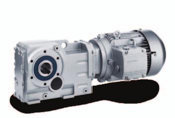
 20 000 Nm 200 kw 0.05... 1 085 / min Helical geared motor D/Z Parallel shaft geared motors and gearboxes Torque Power rating (50 Hz) Output speed (50 Hz) 34 000 Nm 200 kw 0.05... 738 / min Parallel shaft geared motor FD/FZ Bevel helical geared motors and gearboxes Torque 20 000 Nm Power rating (50 Hz) 200 kw Output speed (50 Hz) 0.")
 Output speed (50 Hz) 11 Nm 1.1 kw 8.5... 5 / min Worm geared motor S Siemens D 87.1 2011 1/3")
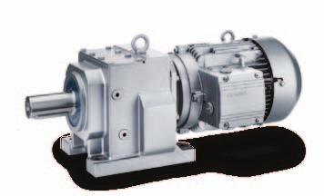
13 MOTOX Geared Motors Description of the range of geared motors (continued) Guide to selecting and ordering geared motors Helical geared motors and gearboxes 1 Torque Power rating (50 Hz) Output speed (50 Hz) Nm 200 kw / min Helical geared motor D/Z Parallel shaft geared motors and gearboxes Torque Power rating (50 Hz) Output speed (50 Hz) Nm 200 kw / min Parallel shaft geared motor FD/FZ Bevel helical geared motors and gearboxes Torque Nm Power rating (50 Hz) 200 kw Output speed (50 Hz) / min Bevel helical geared motor K Helical worm geared motors and gearboxes Torque Power rating (50 Hz) Output speed (50 Hz) Nm 9.2 kw / min Helical worm geared motor C Worm geared motors and gearboxes Torque Power rating (50 Hz) Output speed (50 Hz) 11 Nm 1.1 kw / min Worm geared motor S Siemens D /3
14 MOTOX Geared Motors Siemens AG 2011 Guide to selecting and ordering geared motors 1 Guide to drive selection This "guide to drive selection" takes you to the geared motor you require in easy-to-follow steps. 1st step Determine the required product profile, the following are required: 2nd step Determine the range of possible geared motors 3rd step Determine the basic order number 4th step Complete the order number Technical requirements of the geared motor -> see the "Configuring guide" section of this chapter Gearbox type Power rating Output speed Service factor Radial force Ambient temperature Preselection of the geared motor -> see subsequent pages Size of the gearbox and the motor in accordance with the power rating and output speed Detailed selection of the geared motor -> see the individual chapters for the different gearbox types Define the order number in accordance with the power / torque and output speed Add more details to the order number in accordance with the mounting type, shaft, and mounting position of the geared motor Define the order code for the mounting type / mounting position Selection of motor options -> see chapter "Technical explanations and motor options" Add more details to the order number in accordance with the voltage and frequency Define additional components and the associated order codes 1/4 Siemens D
15 MOTOX Geared Motors Order number code The order number consists of a combination of digits and letters and is divided into three blocks linked with hyphens for a better overview, e.g.: 2KJ1503-1CE13-1AE2-Z +D0+M55 The first block (positions 1 to 7) identifies the gearbox type, the second (positions 8 to 12) codes the output shaft and the motor type and additional design characteristics are coded in the third block (positions 13 to 1). Guide to selecting and ordering geared motors Ordering data: Complete order number, with a -Z suffix, and order code(s) or plain text. If a quotation is available, please specify the quotation number in addition to the order number. When ordering a complete geared motor as a spare part, please specify the works serial number for the previously supplied geared motor as well as the order number. 1 Structure of the order number Position MOTOX geared motors 1st to 5th Helical gearbox E, 1-stage 2 K J 1 0 positions: Helical gearbox Z, 2-stage 2 K J 1 1 Digit, letter, Helical gearbox D, 3-stage 2 K J 1 2 letter, digit, digit Parallel shaft gearbox FZ, 2 K J stage Parallel shaft gearbox FD, 2 K J stage Bevel helical gearboxes B and K 2 K J 1 5 Helical worm gearbox C 2 K J 1 Worm gearbox S 2 K J 1 7 th and 7th Gearbox size positions: Digit, digit 8th position: Output shaft Digit 9th to 10th positions: Letter Letter 11th position: Digit 12th position: Digit 13th position: Digit 14th position: Letter 15th to 1th positions: Letter, digit Motor size Without motor Standard motor 0 1 Motor generation 3 Frequency, voltage Foot-mounted design Foot / flange-mounted design Torque arm Extruder flange Flange-mounted design (A-type) Housing flange (C-type) Mixer flange Agitator flange Transmission ratio Special order versions: Coded: order code also required Non-coded: plain text also required A B D E F H M R Z Siemens D /5
16 MOTOX Geared Motors Siemens AG 2011 Guide to selecting and ordering geared motors 1 Order number code (continued) Ordering example: A bevel helical geared motor is required: Gearbox type / gearbox size K48 Motor 0.37 kw, 4-pole with 50 Hz line frequency Output speed 13, transmission ratio i = Solid shaft V 30 x 0 Mounting type / mounting position B3-00-A Terminal box position 1A This results in the order number and order codes below: Selection criteria Requirements Structure of the order number Gearbox type Bevel helical gearbox K, size 48 2KJ Output shaft Solid shaft V 30 x 0 2KJ Motor size Size 71; 0.37 kw; 4-pole 2KJ1503-1CE Motor type Standard motor 2KJ1503-1CE Motor generation LA / LG 2KJ1503-1CE Frequency, line voltage 50 Hz, / V, D/Y (S100) 2KJ1503-1CE Mounting type Foot-mounted design 2KJ1503-1CE13-1A77 Transmission ratio i = KJ1503-1CE13-1AE2 Mounting position B3-00-A 2KJ1503-1CE13-1AE2-Z+D0 Terminal box position 1A 2KJ1503-1CE13-1AE2-Z+D0+M55 1/ Siemens D
17 MOTOX Geared Motors Determining the gearbox type in accordance with the power rating and output speed Guide to selecting and ordering geared motors 1 Power rating Output speed Torque Gearbox ratio For further information, P Motor n 2 (50 Hz) T 2 i tot see page kw (50 Hz) rpm Nm Helical geared motors E, D, and Z / /8 2/ /11 2/ /15 2/ /19 2/ /22 2/ /2 2/ /30 2/ /34 2/ /39 2/ /44 2/ /49 2/ /54 2/ /59 2/ /4 2/ /7 2/ /70 2/ /74 2/ /77 2/ /80 2/ /83 2/ /85 2/ /88 2/ /89 2/ /91 2/ / / / /92 Parallel shaft geared motors FZ and FD / / 3/ /9 3/ /12 3/ /15 3/ /18 3/ /20 3/ /23 3/ /2 3/ /30 3/ /33 3/ /37 3/ /39 3/ /42 3/ /45 3/ /47 3/ /49 3/ /51 3/ /53 3/ /55 3/5 Siemens D /7
18 MOTOX Geared Motors Siemens AG 2011 Guide to selecting and ordering geared motors 1 Determining the gearbox type in accordance with the power rating and output speed (continued) Power rating Output speed Torque Gearbox ratio For further information, P Motor n 2 (50 Hz) T 2 i tot see page kw (50 Hz) rpm Nm Parallel shaft geared motors FZ and FD /5 3/ /58 3/ /59 3/ / /1 3/ /2 3/ / / /3 3/3 Bevel helical geared motors B and K / / 4/ /9 4/ /12 4/ /15 4/ /18 4/ /21 4/ /25 4/ /29 4/ /32 4/ /35 4/ /38 4/ /41 4/ /43 4/ /45 4/ /47 4/ /49 4/ /50 4/ /52 4/ /53 4/ /54 4/ /5 4/ / / / / / / /59 Helical worm geared motors C / /7 5/ /9 5/ /10 5/ /12 5/ /14 5/ /15 5/ /1 5/ /18 5/ /20 5/21 1/8 Siemens D
19 MOTOX Geared Motors Guide to selecting and ordering geared motors Determining the gearbox type in accordance with the power rating and output speed (continued) 1 Power rating Output speed Torque Gearbox ratio For further information, P Motor n 2 (50 Hz) T 2 i tot see page kw (50 Hz) rpm Nm Helical worm geared motors C /21 5/ /22 5/ / / / / /24 Worm geared motors S / /5... / /... / /7... / / / / /9 Siemens D /9
20 MOTOX Geared Motors Siemens AG 2011 Guide to selecting and ordering geared motors 1 Determining the gearbox type in accordance with the max. torque, transmission ratio, and size Max. gearbox Gearbox type Order No. Transmission ratio For further information, torque Nm see page Helical gearbox E 82 E38 2KJ / E48 2KJ / E8 2KJ / E88 2KJ / E108 2KJ / E128 2KJ / E148 2KJ /95 Helical gearbox Z 90 Z18 2KJ /9 140 Z28 2KJ / Z38 2KJ / Z48 2KJ / Z8 2KJ / Z88 2KJ / Z108 2KJ / Z128 2KJ / Z148 2KJ / Z18 2KJ / Z188 2KJ / Z38 - Z28 2KJ / Z38 - D28 2KJ /98 Helical gearbox D 90 D18 2KJ /9 140 D28 2KJ / D38 2KJ / D48 2KJ / D8 2KJ / D88 2KJ / D108 2KJ / D128 2KJ / D148 2KJ / D18 2KJ / D188 2KJ / D48 - Z28 2KJ / D48 - D28 2KJ / D8 - Z28 2KJ / D8 - D28 2KJ / D88 - Z28 2KJ / D88 - D28 2KJ / D108 - Z38 2KJ / D108 - D38 2KJ / D128 - Z38 2KJ / D128 - D38 2KJ / D128 - Z48 2KJ / D148 - Z38 2KJ / D148 - D38 2KJ / D148 - Z48 2KJ / D18 - Z48 2KJ / D18 - D48 2KJ / D18 - Z8 2KJ / D188 - Z48 2KJ /114 1/10 Siemens D
21 MOTOX Geared Motors Guide to selecting and ordering geared motors Determining the gearbox type in accordance with the max. torque, transmission ratio, and size (continued) 1 Max. gearbox Gearbox type Order No. Transmission ratio For further information, torque Nm see page Helical gearbox D D188 - D48 2KJ / D188 - Z8 2KJ /114 Parallel shaft gearbox FZ 150 FZ28 2KJ /5 290 FZ38B 2KJ /7 540 FZ48B 2KJ / FZ8B 2KJ / FZ88B 2KJ / FZ108B 2KJ / 100 FZ128B 2KJ / FZ148B 2KJ / FZ18B 2KJ / FZ188B 2KJ / FZ208 2KJ / FZ38B - Z28 2KJ / 290 FZ38B - D28 2KJ / Parallel shaft gearbox FD 150 FD28 2KJ /5 290 FD38B 2KJ /7 540 FD48B 2KJ / FD8B 2KJ / FD88B 2KJ / FD108B 2KJ / 100 FD128B 2KJ / FD148B 2KJ / FD18B 2KJ / FD188B 2KJ / FD208 2KJ / FD48B - Z28 2KJ /8 540 FD48B - D28 2KJ / FD8B - Z28 2KJ / FD8B - D28 2KJ / FD88B - Z28 2KJ / FD88B - D28 2KJ / FD108B - Z38 2KJ / FD108B - D38 2KJ / FD128B - Z38 2KJ /7 100 FD128B - D38 2KJ /7 100 FD128B - Z48 2KJ / FD148B - Z38 2KJ / FD148B - D38 2KJ / FD148B - Z48 2KJ / FD18B - Z48 2KJ / FD18B - D48 2KJ / FD18B - Z8 2KJ / FD188B - Z48 2KJ / FD188B - D48 2KJ / FD188B - Z8 2KJ / FD208 - Z8 2KJ / FD208 - D8 2KJ / FD208 - Z88 2KJ /84 Siemens D /11
22 MOTOX Geared Motors Siemens AG Guide to selecting and ordering geared motors Determining the gearbox type in accordance with the max. torque, transmission ratio, and size (continued) Max. gearbox torque Nm Gearbox type Order No. Transmission ratio For further information, Bevel helical gearbox B and K 130 B28 2KJ /0 250 B38 2KJ /1 250 K38 2KJ /3 450 K48 2KJ /5 820 K8 2KJ /7 150 K88 2KJ / K108 2KJ / K128 2KJ / K148 2KJ / K18 2KJ / K188 2KJ / K38 - Z28 2KJ /2 250 K38 - D28 2KJ /2 450 K48 - Z28 2KJ /4 450 K48 - D28 2KJ /4 820 K8 - Z28 2KJ / 820 K8 - D28 2KJ / 150 K88 - Z28 2KJ /8 150 K88 - D28 2KJ / K108 - Z38 2KJ / K108 - D38 2KJ / K108 - Z48 2KJ / K128 - Z38 2KJ / K128 - D38 2KJ / K128 - Z48 2KJ / K148 - Z38 2KJ / K148 - D38 2KJ / K148 - Z8 2KJ / K18 - Z48 2KJ / K18 - D48 2KJ / K18 - Z8 2KJ / K188 - Z8 2KJ / K188 - D8 2KJ / K188 - Z88 2KJ /78 Helical worm gearbox C 118 C28 2KJ /25 5/2 243 C38 2KJ /28 5/ C48 2KJ /32 5/34 87 C8 2KJ /3 5/ C88 2KJ /40 5/ C38 - Z28 2KJ / C38 - D28 2KJ /27 39 C48 - Z28 2KJ /31 34 C48 - D28 2KJ /31 80 C8 - Z28 2KJ /35 C8 - D28 2KJ / C88 - Z28 2KJ / C88 - D28 2KJ /39 Worm gearbox S see page 33 S08 2KJ /10... /10 4 S18 2KJ /10... /10 11 S28 2KJ /10... /10 1/12 Siemens D
23 MOTOX Geared Motors Overview of "special versions" Guide to selecting and ordering geared motors 1 Order code Special version For further information, Designation Input units see page A00 Input unit A with free input shaft 7/3, 7/30 A03 Input unit K2 (coupling lantern) 7/3, 7/20 with flexible coupling for connecting an IEC motor A04 Input unit K4 (short coupling lantern) 7/3, 7/23 with clamp connection for connecting an IEC motor A07 Input unit KQ (lantern for servomotor) 7/3, 7/28 with zero-free, flexible coupling for connecting a servomotor (with feather key) A08 Input unit KQS attachment (lantern for servomotor) 7/3, 7/28 with zero-free, flexible coupling for connecting a servomotor (with plain shaft) A09 Input unit P with free input shaft and piggy back for connecting an IEC motor 7/3, 7/33 A10 Input unit PS with free input shaft, piggy back and protective belt cover 7/3 N1 Size index.2 for KQ/KQS coupling lantern for servomotor 7/3 N2 Size index.3 for KQ/KQS coupling lantern for servomotor 7/3 N3 Size index.4 for KQ/KQS coupling lantern for servomotor 7/3 Backstop in the input unit A15 Backstop X 7/18 Coupling types and input unit options A1 Flexible coupling 7/3 A17 Friction clutch 7/18 A18 Proximity switch 7/18 A19 Speed monitor 7/18 Piggy back position A22 3h 7/33 A23 9h 7/33 A24 12h 7/33 Brake type B00 to B Brake types according to size and braking torque 8/29 8/30 Brake design C01 Enclosed brake 8/42 C02 Manual brake release lever 8/39 C03 Manual brake release lever with locking mechanism 8/39 C04 Microswitch for release monitoring 8/38 C0 Reduced-noise rotor-hub connection and wear-resistant friction lining 8/3 C09 Basic anti-corrosion protection 8/42 C10 Increased anti-corrosion protection 8/42 C11 Enclosed brake with condensation drain hole 8/42 Manual brake release lever position C2 1 8/39 C27 2 8/39 C28 3 8/39 C29 4 8/39 Brake control voltage C4... C70 Brake standard voltage 8/32 Mounting types / mounting positions D00 to E17 Geared motor mounting types and mounting positions 2/ /129, 3/ /95, 4/ /91, 5/ /49, /15 Torque arm figure G09 Figure 1 4/81, 5/44 G10 Figure 2 4/81, 5/44 Output shaft bearings G20 Radially reinforced output shaft bearings 2/133, 3/99, 4/95, 5/53 Siemens D /13
24 MOTOX Geared Motors Siemens AG 2011 Guide to selecting and ordering geared motors 1 Overview of "special versions" (continued) Order code Special version For further information, Designation see page Output sealing G22 + G31 Double radial shaft seal 2/132, 3/98, 4/94, 5/52 G23 Double sealing MSS1 2/132, 3/98, 4/94, 5/52 G24 Combination shaft sealing 2/132, 3/98, 4/94, 5/52 G25 High temperature resistant sealing 2/132, 3/98, 4/94, 5/52 Oil level control G34 Oil sight glass 2/130, 3/9, 4/93, 5/50 Gearbox ventilation G44 Vent filter 2/131, 3/97, 4/93, 5/51 G45 Pressure ventilation valve 2/131, 3/97, 4/93, 5/51 Oil drain G53 Magnetic oil drain plug 2/131, 3/97, 4/94, 5/51 G54 Oil drain valve, straight 2/131, 3/97, 4/94, 5/51 Hollow-shaft cover G0 Steel protection cover 3/99, 4/95, 5/52 G1 Steel protection cover (ATEX) 3/99, 4/95, 5/52 G2 Protection cover 3/99, 4/95, 5/52 G3 Protection cover (ATEX) 3/99, 4/95, 5/52 Backstop for bevel helical gearbox G72 Backstop (gearbox) 4/9 Options for gearbox output shafts G73 2nd shaft extension (output shaft on both sides) 4/9, 5/53, /1 Dry-well options for mixer and agitator drives G89 Dry-well design with sight glass 2/133, 3/100, 4/97 G90 Dry-well design with sensor 2/133, 3/100, 4/97 Reduced-backlash version G99 Reduced-backlash version 1/23, 2/93, 3/5, 4/2 Flange diameter H01 to H0 Flange diameter 2/118, 3/91, 4/8, 5/4, /14 Degree of protection K01 IP 55 8/8 K02 IP 5 8/8 K03 IP 5 8/8 Lubricants K0 CLP ISO VG Mineral oil 1/4, 2/130, 3/94, 4/92 K07 CLP ISO PG VG Synthetic oil 1/4, 2/130, 3/9, 4/92 K08 CLP ISO PG VG 40 - Synthetic oil 1/4, 2/130, 3/9, 4/92, 5/50, /1 K10 CLP ISO E VG Biologically degradable oil 1/4, 2/130, 3/9, 4/92, 5/50 K11 CLP ISO H1 VG 40 - Oil for use in the food industry 1/4, 2/130, 3/9, 4/92, 5/50, /1 K12 CLP ISO PAO VG Oil for low temperature usage 1/4, 2/130, 3/9, 4/92, 5/50 K13 CLP ISO PAO VG 8 - Oil for lowest temperature usage 1/4, 2/130, 3/9, 4/92 Long-term preservation K17 Long-term preservation up to 3 months 1/4 Direction of rotation of the output shaft (required with backstop) K18 Clockwise 1/43, 4/9 K19 Counterclockwise 1/43, 4/9 Rating plate and additional rating plates K2 Rating plate on stainless steel support plate 1/49 K41 2nd rating plate, enclosed separately 1/49 K8 2nd rating plate, mounted 1/49 1/14 Siemens D
25 MOTOX Geared Motors Overview of "special versions" (continued) Guide to selecting and ordering geared motors 1 Order code Special version For further information, Designation Surface treatment L00 Unpainted 1/48 L01 Primed according to corrosion category C2 G 1/48 L02 Surface protection for normal environmental stress 1/47 L03 Surface protection for minimal environmental stress 1/47 L04 Surface protection for medium environmental stress 1/47 L05 Surface protection for extremely high environmental stress 1/47 L09 Primed according to corrosion category C4 G 1/48 L19 Special pre-treatment before painting 1/48 L20 Surface protection for high environmental stress 1/47 RAL colors L50 RAL 5015 Sky blue 1/48 L51 RAL 7011 Steel gray 1/48 L53 RAL 7031 Blue gray 1/48 L54 RAL 7035 Light gray 1/48 L55 RAL 7030 Stone gray 1/48 Other colors can be selected by entering order code Y80 and plain text 1/48 Insulating material class M08 Temperature class 180 (H) 8/25 M09 Special insulation for inverter-fed operation up to 90 V 8/25 Thermal motor protection M10 PTC thermistor for disconnection 8/23 M11 PTC thermistor for warning and disconnection 8/23 M12 Winding thermostat for disconnection (WT) 8/23 M13 Winding thermostat for warning and disconnection for sizes 71 to 200 (WT) 8/23 M1 KTY temperature sensor 8/24 Fan M21 Metal fan 8/9 M22 High inertia fan 8/9 M23 External fan 8/10 Anti-condensation heating M V supply voltage 8/24 M V supply voltage 8/24 Terminal box position M55 to M8 Location and position of the terminal box 8/11 ECOFAST motor plugs N04 ECOFAST motor plug HAN 10E (single-bracket lock) 8/18 N05 ECOFAST motor plug HAN 10E with counterplug HAN 10B (single-bracket lock) 8/18 N0 ECOFAST motor plug HAN 10E, EMC design (single-bracket lock) 8/18 N07 ECOFAST motor plug HAN 10E with counterplug HAN 10B, 8/18 EMC design (single-bracket lock) Canopy N22 Canopy 8/8 Backstop on motor N23 Motor backstop 8/3 2nd shaft extension on motor N39 2nd shaft extension 8/4 Handwheel N40 Handwheel 8/5 Motor side B, can be retrofitted N48 Motor side B, can be retrofitted 8/2 see page Siemens D /15
26 MOTOX Geared Motors Siemens AG Guide to selecting and ordering geared motors Overview of "special versions" (continued) Order code Special version For further information, Designation Additional feet N49 Additional feet 8/5 Designs in accordance with standards and specifications N30 Design in accordance with GOST-R 1/40, 8/3 N3 Design in accordance with CSA 1/40, 8/3 N37 Design in accordance with UL-R 1/40, 8/3 N38 Design in accordance with UL-R and CSA 1/40, 8/3 N5 Design in accordance with NEMA (electrical) 1/39, 8/3 N7 Design in accordance with CCC 1/40, 8/3 N9 Design in accordance with China Energy Efficiency Label 1/40, 8/3 Versions for special environmental conditions N41 Motor-internal anti-corrosion protection 8/19 Protection against humidity and acid N43 Increased protection against humidity and tropical climate 1/48 N44 Increased protection against acid and alkali 1/48 N54 Motor winding protection against humidity and acid 8/2 External earthing N53 External earthing 8/19 Motors prepared for encoder mounting N50 Encoder mounting prepared 8/0 Pole number of the motor see page P00 2-pole 8/8, 8/8, 8/9 P01 -pole 8/70, 8/84, 8/70, 8/98, 8/102, 8/132, 8/13, 8/132, 8/13 P02 8-pole 8/72, 8/8, 8/104, 8/122, 8/128 P04 4/2-pole 8/74, 8/10 P08 8/4-pole 8/7, 8/78 P07 8/2-pole 8/80 Gateways EnDAT for absolute encoders Q02 Gateway EnDAT Profibus DP 8/3 Q03 Gateway EnDAT CANopen 8/3 Q04 Gateway EnDAT DeviceNET 8/3 Incremental encoder IN Q44 Rotary pulse encoder 1XP (IN 1024 TTL with coupling socket) 8/51 Q45 Rotary pulse encoder 1XP (IN 2048 TTL with coupling socket) 8/51 Q4 Rotary pulse encoder 1XP (IN 512 TTL with coupling socket) 8/51 Q47 Rotary pulse encoder 1XP (IN 1024 HTL with coupling socket) 8/51 Q48 Rotary pulse encoder 1XP (IN 2048 HTL with coupling socket) 8/51 Q49 Rotary pulse encoder 1XP (IN 512 HTL with coupling socket) 8/51 Q50 Rotary pulse encoder 1XP (IN 1024 TTL with flange socket) 8/50 Q51 Rotary pulse encoder 1XP (IN 2048 TTL with flange socket) 8/50 Q52 Rotary pulse encoder 1XP (IN 512 TTL with flange socket) 8/50 Q53 Rotary pulse encoder 1XP (IN 1024 HTL with flange socket) 8/50 Q54 Rotary pulse encoder 1XP (IN 2048 HTL with flange socket) 8/50 Q55 Rotary pulse encoder 1XP (IN 512 HTL with flange socket) 8/50 Q5 Rotary pulse encoder 1XP (IN 1024 TTL with cable terminal box) 8/52 Q57 Rotary pulse encoder 1XP (IN 2048 TTL with cable terminal box) 8/52 Q58 Rotary pulse encoder 1XP (IN 512 TTL with cable terminal box) 8/52 Q59 Rotary pulse encoder 1XP (IN 1024 HTL with cable terminal box) 8/52 Q0 Rotary pulse encoder 1XP (IN 2048 HTL with cable terminal box) 8/52 Q1 Rotary pulse encoder 1XP (IN 512 HTL with cable terminal box) 8/52 1/1 Siemens D
27 MOTOX Geared Motors Overview of "special versions" (continued) Guide to selecting and ordering geared motors 1 Order code Special version For further information, Designation see page Cable terminal boxes for encoders 1XP8012, 1XP8032, 1XP8013, 1XP8023.1XP8014 and 1XP8024 Q2 Connector 8/1 Q9 Cable with connector and ferrules, 2 m 8/1 Q70 Cable with connector and ferrules, 8 m 8/1 Q71 Cable with connector and ferrules, 15 m 8/1 Q72 Cable with coupling socket, 2 m 8/2 Q73 Cable with coupling socket, 8 m 8/2 Q74 Cable with coupling socket, 15 m 8/2 Cable terminal boxes for encoders 1XP8022 Q3 Cable with ferrules, 2 m 8/1 Q4 Cable with ferrules, 8 m 8/1 Q5 Cable with ferrules, 15 m 8/1 Q Cable with coupling socket, 2 m 8/2 Q7 Cable with coupling socket, 8 m 8/2 Q8 Cable with coupling socket, 15 m 8/2 Absolute encoder IA Q80 Absolute encoder 1XP (IA SSI protocol with flange socket) 8/55 Q81 Absolute encoder 1XP (IA SSI protocol cable with coupling socket) 8/55 Q82 Absolute encoder 1XP (IA EnDAT protocol with flange socket) 8/55 Q83 Absolute encoder 1XP (IA EnDAT protocol cable with coupling socket) 8/55 Resolver IR Q85 Resolver 1XP (IR with flange socket) 8/54 Q8 Resolver 1XP (IR cable with coupling socket) 8/54 Q87 Resolver 1XP (IR with flange socket) 8/54 Q88 Resolver 1XP (IR cable with coupling socket) 8/54 Rugged encoder Q92 Rotary pulse encoder LL Leine & Linde 8/57 Q93 Rotary pulse encoder HOG 9 8/58 Q94 Rotary pulse encoder HOG 10 8/59 Mechanical protection Q95 Encoder under cover 8/0 Siemens D /17
28 MOTOX Geared Motors Siemens AG 2011 Configuring guide 1 Determining the drive data Data relating to the machine to be driven (machine type, mass, input speed, speed range, etc.) is required in order to size the machine correctly. This data is then used to determine the required power rating, torque, and input speed of the geared motor. The correct drive can be selected based on its calculated power rating and speed. Data required for selection The following data is required in order to select the correct gearbox: 1. Type of driven machine 2. Daily operating time h 3. Required input power kw or required torque Nm 4. Required output speed n 2 of the geared motor rpm or gearbox ratio i 5. Operating voltage V and frequency Hz. Operating mode, number of startings, inverter-fed operation, type of startup 7. Moment of inertia J Load kgm 2 of the driving machine reduced to the motor shaft 8. Type of power transmission on gearbox shafts (direct, coupling, belt, chain, gear wheel) 9. Radial force F r N at the input shaft and direction of force with distance from the shaft shoulder to the point of application and axial force F ax [N] with direction of force 10. Ambient temperature C 11. Degree of protection 12. Mounting position 13. Required braking torque Nm 14. Any regulations (CSA, VIK, etc.) 1/18 Siemens D
29 Efficiency of the geared motor The efficiency of the gearbox is determined by the gear teeth, rolling-contact bearing friction, and the shaft sealing rings, among other things. The starting efficiency also has to be taken into account, particularly as regards helical worm and worm gearboxes. Efficiency may be impaired at high input speeds, if a relatively large amount of oil is used (depending on mounting position), and during cold operation in low temperature ranges. Siemens AG 2011 MOTOX Geared Motors Configuring guide 1 Helical, bevel helical, and parallel shaft gearboxes MOTOX helical, parallel shaft, and bevel helical gearboxes are extremely efficient. As a rule, efficiencies of 98 % (1-stage), 9 % (2-stage), and 94 % (3-stage) can be assumed. Helical worm and worm gearboxes The gear teeth of the worm gearboxes lead to high sliding friction losses at high transmission ratios. Therefore, these gearboxes can be less efficient than other types. The efficiencies of the helical worm and worm gearboxes primarily depend on the transmission ratio in question. With helical worm gearboxes, some of the transmission ratio is realized by the helical gear stage. In this way, higher degrees of efficiency can be achieved. For further information see the chapter dealing with helical worm gearboxes. Self-locking with worm gearboxes In respect of restoring torques on worm gearboxes, the efficiency is considerably reduced in comparison to standard efficiency. The restoring efficiency can be calculated as follows: η ' = 2-1/η. At a standard efficiency of η 0.5, worm gearboxes are usually self-locking, which is determined by the particular lead angle of the worm gear teeth. Self-locking only occurs with certain combinations of MOTOX gearboxes and is not always of benefit, as the associated loss of efficiency is then relatively high, which in turn requires increased motor power. A worm gearbox is "self-locking while stationary" (static self-locking), if it is not possible to start from stationary when the worm wheel is driving. A worm gearbox is "self-braking while running" (dynamic selflocking), if it is not possible to continue running when the worm wheel is driving while the gearbox is running that is, if the running gearbox comes to a stop while the worm wheel is driving. Shocks can neutralize self-locking. A self-locking gearbox is, therefore, no substitute for a brake or backstop. If you want to use the self-locking braking effect for a technical purpose, please contact us. Run-in phase for helical worm and worm gearboxes The tooth flanks on new helical worm and worm gearboxes will not yet be fully smoothed, meaning that the friction angle will be greater and efficiency lower during initial operation. The higher the transmission ratio, the more pronounced the effect. The run-in procedure should take approximately 24 hours of operation at full load. In most cases, the catalog values will then be reached. Losses of splashing With certain gearbox mounting positions, the first stage can become completely immersed in the gear lubricant. In the case of large gearboxes with a high input speed, particularly with vertical mounting positions, this may lead to increased losses of splashing, which must not be ignored. Please contact us if you want to use such gearboxes. If at all possible, you should choose horizontal mounting positions in order to keep losses of splashing to a minimum. Siemens D /19
30 MOTOX Geared Motors Siemens AG 2011 Configuring guide 1 Determining the required service factor The operating conditions are crucial in determining the service factor and for selecting the geared motor. These conditions are taken into account with service factor f B. The gearbox size or rated gear torque and the resulting service factor are not standardized and depend on the manufacturer. In standard operation, i.e. with a uniform load provided by the driving machine, small masses to be accelerated, and a low number of startings, the service factor of f B = 1 can be selected. For different operating conditions see the tables found under "Service factor". If the motor power and the gearbox output speed are known, a gearbox type is selected with a service factor that meets the following condition. f Btot f B The mass acceleration factor m AF is calculated as follows: m AF = J Load J M + J B + J add ( ) All external moments of inertia are moments of inertia of the driving machine and the gearbox, which are to be reduced to the motor speed. In most cases the moment of inertia of the gearbox has no effect and can be ignored. The calculation is made using the following formula: n 2 J Load = J n 1 2 = J i 2 For drives operating under special conditions, e.g. frequent reversing, short-time or intermittent duty, abnormal temperature ratios, reversal braking, extreme or rotating transverse forces on the gear output shaft, etc. please contact us for advice on how to design the drive configuration. The operating conditions can vary greatly. To determine the service factor, empirical values can be derived from the configuration of other similar applications. The driving machines can be assigned to three load groups according to their shock load. These groups can be assessed by means of their mass acceleration factor (m AF ). In the case of high mass acceleration factors (m AF >10), a large amount of play in the transmission elements, or high transverse forces, unexpected additional loads may arise. Please contact us in such an event. Code Description Unit f Btot Service factor of the driving machine f B Service factor of the geared motor m AF Mass acceleration factor J Load All external moments of inertia kgm² (based on the motor shaft) J M Moment of inertia of the motor kgm² J B Moment of inertia of the brake kgm² J add Additional moment of inertia (e.g. centrifugal mass or high inertia fan) kgm² J 2 Moment of inertia based on the output speed kgm² of the gearbox n 1 Input speed of the motor rpm n 2 Output speed of the gearbox rpm i Gearbox ratio DC Relative duty cycle % 1/20 Siemens D
31 MOTOX Geared Motors Required service factor Service factor for helical, parallel shaft, and bevel helical gearboxes The service factor of the driving machine f Btot is determined from the tables by taking the load classification, number of startings, and duration of service per day into account. Contact our drive experts to check drive sizing in the case of high shock loads and, for example, high motor and braking torques that are greater than 2.5x the rated motor torque. f Btot = f B1 Service factors f B1 : Load classification for driving machines Shock load I Light shock loads II Moderate shock loads III Heavy shock loads Configuring guide Driving machine Mass acceleration factor 0.3: Electric generators, belt conveyors, apron conveyors, screw conveyors, lightweight elevators, electric hoists, machine tool feed drives, turbo blowers, centrifugal compressors, mixers and agitators for uniform densities. Mass acceleration factor 3: Machine tool main drives, heavyweight elevators, turning tools, cranes, shaft ventilators, mixers and agitators for non-uniform densities, piston pumps with multiple cylinders, metering pumps. Mass acceleration factor 10: Punching presses, shears, rubber kneaders, machinery used in rolling mills and the iron and steel industry, mechanical shovels, heavyweight centrifuges, heavyweight metering pumps, rotary drilling rigs, briquetting presses, pug mills. 1 Daily operating duration 4 hours 8 hours 1 hours 24 hours Starts* ) / h < > 200 < > 200 < > 200 < > 200 Shock load I II III * ) The number of startings is calculated from the sum of times it is switched on, braking operations, and changeovers. Service factors for helical worm and worm gearboxes: With worm gearboxes, two additional service factors are used, which take the duty cycle and ambient temperature into account. These additional factors can be determined from the graph opposite. f Btot = f B1 f B2 f B3 In the standard version the gearboxes can operate at an ambient temperature of 20 C to +40 C. In the case of a service factor f B3 < 1 for temperatures below 20 C please contact us. Service factor f B2 for short-time duty: 1.0 f 0.9 B G_M015_EN_ DC [%] DC = Loadingttime in min h Siemens D /21
32 MOTOX Geared Motors Siemens AG 2011 Configuring guide 1 Required service factor (continued) Example worm gearbox: Mass acceleration factor 2.5 (shock load II), runtime 15 hours per day (read off at 1 hours), and 70 starts / h gives a service factor of f B1 = 1.4 for service factor f B1 according to the table. A load duration of 30 minutes per hour gives a duty cycle (DC) of 50 %. According to the diagram, this results in a service factor of f B = 0.94 for service factor f B2. At an ambient temperature of ϑ amb = 20 C, the diagram gives a service factor of f B3 = 1.0 for service factor f B3. So, the required service factor is f Btot = = Service facor f B3 for the ambient temperature: f B G_M015_EN_ ϑ amb = Ambient temperature [ C] amb Maximum motor speed At high motor speeds (>1.500 rpm) you will generally experience higher than average noise emissions and a lower than average bearing service life. This depends to a large extent on the transmission ratio and gearbox size in question. Furthermore, high speeds affect the thermal properties and service intervals of the gearbox. The maximum input speed of the gearbox is usually 3.00 rpm. If you require higher speeds, please contact us. Ambient temperature In the standard version the gearboxes can operate at an ambient temperature of 20 C to +40 C, if the lubricant recommendations are kept. In the case of a few additional options the category temperatures must be checked. Other temperature ranges -10 C C on request. Required torque T 2req If the drive data and the service factor are selecetd, the required output torque can be determined P 1 T 2req = f n Btot 2 Selection of the gearbox The following conditions need to be observed: P 1 > P req T 2rated > T 2req f B > f Btot T 2 > T req Code Description Unit f Btot Service factor of the driving machine f B Service factor of the geared motor P 2m Input power of the motor kw P req Required input power kw T req Required torque Nm T 2 Output torque of the geared motor Nm T 2rated Nominal output torque of the geared motor Nm T 2req Required output torque of the driving machine Nm 1/22 Siemens D
33 MOTOX Geared Motors Reduced-backlash gearbox version Helical, parallel shaft and bevel-helical gearboxes are available on request in a reduced-backlash version. In the transmission table, the torsion angle (ϕ) is specified for the reduced-backlash version. If a value is not specified, this gearbox cannot be realized with reduced backlash. A high degree of positioning accuracy is achieved with reducedbacklash gearboxes and the shock loads in the gearbox are reduced at load changeover. When a gearbox is used that has a certain amount of play, the relative position of the output shaft of the gearbox cannot be determined precisely because the Configuring guide controller cannot detect whether the right or left flank of the tooth is engaged. Accurate positioning and repeatability Maintain position information in the case of a change of direction of rotation Reduced shock loading of the tooth flanks Order code: Reduced-backlash version G99 1 Permissible radial force Available radial force The available radial force F Ravail at the shaft journals results from the available output torque of the geared motor T and the diameter d and type of the output element (e.g. sprocket wheel). The type of output element determines factor C (see table below), by which the available radial force is to be increased. F Ravail 2000 T 2 = C d Code Description Unit F Ravail Available radial force resulting from the output torque and the diameter of the output element N F Rperm Permissible radial force at the center of shaft N extension d Diameter of the input element mm T 2 Output torque of the geared motor Nm F xperm1 Permissible radial force, limited by the N bearing service life, at a distance of x from the shaft shoulder F xperm2 Permissible radial force, limited by the shaft strength, at a distance of x from the shaft shoulder N C Additional factor b, d, l, y, z Gearbox constants mm a Gearbox constant knmm F ax Axial force at d N α Angle of action of the radial force F xperm F Rperm ød x G_M015_EN_0003a F 0 l x l/2 0 Factor C for the type of the transmission element Transmission Design C element Gear wheel >17 teeth teeth 1.15 Sprocket wheel 20 teeth teeth teeth 1.40 Toothed belt Preload 1.50 V belt Preload 2.00 Flat belt Preload 2.50 Agitator / mixer Rotating radial force 2.50 x F xperm F Rperm G_M015_EN_00037a l x l/2 F 0 0 ød Siemens D /23
34 l MOTOX Geared Motors Siemens AG 2011 Configuring guide 1 Permissible radial force (continued) Permissible radial force The permissible radial force F Rperm is determined by the required bearing service life, among other things. The nominal service life L h10 is determined in accordance with ISO 281. The bearing service life can be calculated for special operating conditions on request, based on the calculation procedure for the modified service life L na. Furthermore, the permissible radial force is determined by the housing and shaft strength of the gearbox. The selection tables specify the permissible radial force F Rperm for the output shafts. These values refer to the point of load at the center of the shaft extension and are minimum values, which apply to the worst possible conditions in the gearbox (force angle, mounting position, direction of rotation). If the point of load is not at the center of the shaft extension, the permissible radial force must be calculated as follows: the smaller value of F xperm1 (bearing service life) and F xperm2 (shaft strength) is the permissible radial force. The calculation does not include additional axial forces. If the direction of rotation of the output shaft and the additional axial forces are known, or the values in the table are insufficient, our drive experts have to perform the calculation. Our agitator and mixer drives allow you to achieve higher permissible radial forces. These drives are particularly well suited to large and rotating radial forces. Permissible radial force in accordance with bearing service life for all gearbox types: Permissible radial force in accordance with shaft strength for bevel helical, parallel shaft, and helical worm gearboxes: y F xperm1 = F Rperm ( z + x) F xperm2 a = -- x Permissible radial force in accordance with shaft strength for helical and worm gearboxes: The shaft strength only has to be calculated for solid shafts, with hollow shafts this step can be omitted. F xperm2 = a ( b + x) Higher permissible radial forces The permissible radial force load can be increased, taking the angle of force action α and the direction of rotation into account. Installing reinforced bearings also means that higher loads are permitted on the input shaft. F ax F r F r Permissible axial loads x If no transverse force load is present, an axial force F ax (tension or compression) of around 50 % of the specified radial force with standard bearings can be achieved for gearbox sizes 18 to 148. You can use our "Calculation of input shaft bearing arrangement" assistant in the MOTOX Configurator to calculate the permissible forces. Combined forces with an axial and a radial component can also be calculated. Please contact us in case of doubt. G_D087_XX_00014a The permissible radial forces are specified in the gearbox chapters. 1/24 Siemens D
35 MOTOX Geared Motors Determining the operating mode Configuring guide 1 If no specifications are made in the power tables, the power ratings specified in the power tables apply to the S1 operating mode (continuous duty with constant load) according to EN The same regulation defines the groups of operating modes specified below: Load t B G_D087_EN_00018 Time t B Load duration Operating mode S1 Continuous duty Operating modes in which starting and electrical braking do not affect the overtemperature of the stator winding of the motor: Operating mode S2: Short-time duty t B Operating times of 10, 30, 0, and 90 min. are recommended. After each period of duty the motor remains at zero current until the winding has cooled down to the coolant temperature. Load G_D087_EN_00019 Time t B Load duration Operating mode S2 Short-time duty Operating mode S3: Intermittent duty Starting does not affect the temperature. Unless any agreement is made to the contrary, the cycle duration is 10 minutes. Values of 15 %, 25 %, 40 %, and 0 % are recommended for the cyclic duration factor. Load t B G_D087_EN_00020 t s t St Time t B t s t St Load duration Cycle duration Standstill time Cyclic duration factor based on 10 min t B = 100% t B + t St Operating mode S3 Intermittent periodic duty Operating mode S: Continuous duty with intermittent loading Unless any agreement is made to the contrary, the cycle duration here is also 10 minutes. Values of 15 %, 25 %, 40 %, and 0 % are recommended for the load duration factor. Load t P t S t V G_D087_EN_00021 t S t P t V Time Cycle duration Operating time with constant load Idle time Cyclic duration factor (CDF) = t P t S Siemens D /25
36 MOTOX Geared Motors Siemens AG 2011 Configuring guide 1 Determining the operating mode (continued) Operating mode S10: Duty with discrete constant loads In this mode a maximum of four discrete loads are available, of which each load achieves the thermal steady state. A load of the same value as the one used in S1 operating mode should be selected for this operating mode. Load t S t 1 t 2 t 3 t 4 P ref P1 P2 P3 G_D087_EN_00022 P4 Time P i Constant load within one load cycle P ref Reference load t S Cycle duration Operating modes in which starting and braking have a corresponding effect on the overtemperature of the stator winding and of the rotor cage: Operating mode S4: Intermittent duty where starting affects the temperature t s t A t B t St Load G_D087_EN_00023 Time t A t B t s t St Starting time Load duration Cycle duration Standstill time Cyclic duration factor based on 10 min = t A + t B 100% t A + t B + t St Operating mode S4 Intermittent periodic duty with starting Operating mode S5: Intermittent duty where starting and braking affects the temperature For the S4 and S5 operating modes, this code should be followed by the cyclic duration factor, the moment of inertia of the motor (J M ), and the moment of inertia of the load (J Load ), both based on the motor shaft. Unless any agreement is made to the contrary, the cycle duration here is also 10 minutes. Values of 15 %, 25 %, 40 %, and 0 % are recommended for the cyclic duration factor. Load t S t D t P t F t St tf t Pt D t S t St Time Cycle duration Starting time Operating time with constant load Time with electrical braking Standstill time with windings at zero current G_D087_EN_00024 Cyclic duration factor (CDF) = t D + t P + t F t S Operating mode S7: Continuous-operation periodic duty with starting and braking For the S7 and S8 operating modes, the moment of inertia of the load (J Load ) based on the motor shaft must be known. Load t D t S t P t F G_D087_EN_00015 Time t S t D t P t F Cycle duration Starting time Operating time with constant load Time with electrical braking Cyclic duration factor = 1 1/2 Siemens D
37 MOTOX Geared Motors Determining the operating mode (continued) Configuring guide 1 Operating mode S8: Continuous-operation duty with non-periodic load and speed variations (inverter-fed operation) Most of the intermittent operating conditions which occur in real situations are a combination of the operating modes defined above. All operating conditions must be specified in order to accurately define a suitable motor. Load t D t P1 t S t P2 t F1 t F2 t P3 Time G_D087_EN_0001 t S t D t P t F Cycle duration Starting time Operating time with constant load (P1, P2, P3) Time with electrical braking (F1, F2) Cyclic duration factor (CDF) = t D + t P1 t F1 + t P2 t F2 + t P3 t S t S t S Operating mode S9: Continuous-operation duty with non-periodic load and speed variations (inverter-fed operation) Most of the intermittent operating conditions which occur in real situations are a combination of the operating modes defined above. All operating conditions must be specified in order to accurately define a suitable motor. Load P ref t F t P t D t S t St Time G_D087_EN_00017 t D t P t F t St t S Starting time Operating time with constant load Time with electrical braking Standstill time with windings at zero current Time with overload Operating modes according to EN 0034 (IEC ) Operating Description Information required k DC mode S1 Continuous duty with 100 % DC S2 Constant load for brief period, Load duration 0 min 1.10 e.g. S2-30 min 30 min min 1.40 S3 S4 S10 Intermittent periodic duty without starting (cyclic operation), e.g. S3-40 % Intermittent periodic duty with starting Cyclic duration factor DC in % (based on 10 min) According to the table below, the motor list powers can be converted to the lower duty cycle using the corresponding k DC factors for the S1, S2, and S3 operating modes. With enhanced performance, you should note that the breakdown torque ratio must not fall below 1.. T Bd T DC P DC = P rated k DC T DC ~ T rated k DC Cyclic duration factor DC in %, times switched on per hour, load torque, and moment of inertia The operating mode and motor power can be determined if the number of startings per hour, starting time, load duration, type of braking, braking time, idle time, cycle time, standstill time, and required power are specified. 0 % % % % 1.40 On request Code Description Unit P DC Power rating for the new duty cycle P rated Rated motor power kw k DC Factor for enhanced performance kgm² T DC Torque for the new duty cycle Nm T Bd Breakdown torque Nm T rated Rated torque Nm Siemens D /27
38 MOTOX Geared Motors Siemens AG 2011 Configuring guide 1 Coolant temperature and site altitude The rated power specified in the selection tables in section 8 applies to continuous duty (S1) or inverter-fed operation (S9) according to IEC at the corresponding rated frequency, a coolant temperature of 40 C and a site altitude of m above sea level. Please contact us if higher coolant temperatures are to be used. The table containing correction factors provides a rough idea of derating if conditions are different. This results in a permissible motor power of: P perm = P rated k HT If the permissible motor power is no longer adequate for the drive, a check should be performed as to whether or not the motor with the next higher rated power fulfills the requirements. Factor k HT for different site altitudes and / or coolant temperatures Site altitude Coolant temperature (CT) (SA) m < 30 C C 45 C 50 C 55 C 0 C Code Description Unit P perm Permissible motor power kw P rated Rated motor power kw k HT Factor for abnormal coolant temperature and site altitude Selecting the brake MOTOX geared motors can be supplied with fail-safe springoperated disk brakes in order to reduce the motor's follow-on time or to hold loads, for example. Our MODULOG modular system can be used to assign / attach several brake sizes to one motor size. See Chapter 8 for information on assigning brake sizes to motor sizes, and on possible brake options. The following information is required in order to select and check the brake: Speed Load torque Moments of inertia Number of startings 1/28 Siemens D
39 MOTOX Geared Motors Selecting the braking torque The braking torque must be selected in accordance with the particular drive scenario. The following criteria are crucial when it comes to making this selection: static safety, required braking time, permissible deceleration rate, and possible braking distance and brake wear. Configuring guide The ambient conditions and number of startings are also important. Our drive experts will be able to provide optimum brake sizing. 1 In principle the selection is made according to the formula: k T br > T x -- η Where k = is selected. As a general rule of thumb, the factor for horizontal motion is around and for vertical motion around However, the exact specification of the braking torque depends to a large extent on the particular operating conditions. Operating time of the brake The time it takes the motor to come to a standstill comprises the following components: the application time of the brake t 1 and the braking time t br. The first is the time it takes the brake to reach 90 % of its braking torque. This time may be circuit- and actuation-dependent. This information is provided for each brake in Chapter 8. The braking time can be calculated as follows: ( J M + J t add + J x η ) n br br = ( T br ± T x η ) If T x supports the braking operation, T x is positive, otherwise it is negative. Braking distance and positioning accuracy Braking distance s br is the distance traveled by the driven machine during braking time t br and application time t 1. The formula below applies to horizontal motion and upward vertical motion. With linear motion, a positioning accuracy of around ± 15 % can be assumed. However, this can be heavily influenced by the condition of the brake. s br = v 100 (t t br ) Braking energy per braking operation The braking energy W per braking operation comprises the energy of the moments of inertia to be braked and the energy which must be applied in order to brake against a load torque: T x is positive if the load torque is working against the braking torque (horizontal motion, upward vertical motion). T x is negative if it supports the braking operation (downward vertical motion). The permissible operating energy Q perm must be checked against the relevant number of startings using the "Permissible operating energy" diagram (see Chapter 8). This is of particular importance for emergency-stop circuits. [s] [mm] 2 T br ( J M + J W perm + J x η ) n br = T br ± T x η W < Q perm Code Description Unit T br Rated braking torque Nm T x Load torque Nm k Factor for taking operating conditions into kgm² account η Efficiency % t br Braking time s t 1 Application time of the brake ms J mot Moment of inertia of the motor kgm 2 J add Additional moment of inertia kgm 2 (e.g. centrifugal mass or high inertia fan) J x Reduced moment of inertia of the load kgm² n br Braking speed rpm s br Braking distance mm W Friction energy per braking operation J Q perm Permissible operating energy J L rated Service life of the brake lining until h readjustment L ratedmax Service life of the brake lining until h replacement = total service life v Conveying speed m/s W V Friction energy until the brake is adjusted MJ W tot Friction energy until the brake lining MJ is replaced Z Number of startings 1/h Brake service life The brake lining wears due to friction, which increases the air gap and the application time of the brake. The air gap can be readjusted. The friction lining should be replaced after it has been readjusted a certain number of times. Service life of the brake lining until readjustment: W L V rated = W Z Service life of the brake lining until replacement: W L tot ratedmax = W Z Siemens D /29
40 MOTOX Geared Motors Siemens AG 2011 Special versions 1 Motors for inverter-fed operation Selection of motors on the inverter For selecting electrical drives on the inverter, the torque-speed response of the motors and the driving machine is important. With inverter-fed operation, it is particularly important to pay attention to the torque limit curve. The torque of the driving machine must be smaller during continuous operation than the motor limit torque. The design of the motor depends to a large extent on the desired speed control range. In general, a range from 25 to 50 Hz is preferable. The effectiveness of the self-ventilation is reduced with decreasing speed, which in turn also reduces the continuous output torque. Forced ventilation can be used to prevent the torque from decreasing. The fan noise can increase at speeds that are higher than the rated speed of self-ventilated geared motors. Above the frequency limit, the continuous output torque decreases (field weakening). Bearings and bearing currents With operation with inverters, additional bearing currents can occur. They are mainly caused by the steep voltage rises which occur during switching. Without output filters, significant voltage variations can occur on the winding terminals. This phenomenon mainly occurs with larger machines. EMC-compliant installation of the drive system is a basic prerequisite for preventing premature bearing damage via bearing currents. The most important measures for reducing bearing currents: Use of cables with a symmetrical cable cross-section, Use of grounding cables with low impedance in a large frequency range (0 Hz up to approximately 70 MHz), for example, plaited copper ribbon cables, HF litz wires, Separate HF equipotential-bonding cable between the motor housing and the driving machine, Separate HF equipotential-bonding cable between the motor housing and the inverter PE busbar, 30 HF contacting of the cable shield on the motor housing and the inverter PE busbar. This can be achieved using EMC cable glands at the motor end and EMC shield clips at the inverter end, for example, Use of motor reactors, Common-mode filters at the inverter output, Insulated motor bearing at the non-drive end. Motors from size 280 are delivered with bearing insulation for inverter-fed operation. Mechanical stress and grease lifetime High speeds that exceed the rated speed and the resulting increased vibrations alter the mechanical running smoothness and the bearings are subjected to increased mechanical stress. This reduces the grease lifetime and the bearing service life. More detailed information is available on request. L3 L1 L2 PE L3 L1 PE Concentric copper or aluminum shield PE L2 PE L3 Steel armor L1 L2 G_D087_EN_ /30 Siemens D
41 MOTOX Geared Motors Determining the permissible number of startings Z perm Special versions 1 A high number of startings means that the motor winding will be subject to a thermal load. The permissible no-load operating Z 0 for brake motors is specified in the no-load operating tables. The permissible number of startings Z perm has to be determined for different operating cases. This value is influenced by the corresponding load torque, any additional moment of inertia, the power requirement, and the cyclic duration factor. These can be evaluated using the factors k M, k FI, and k P k 0.8 FI G_M015_EN_ Z perm = Z 0 k M k FI k P Code Description Unit J mot Moment of inertia of the motor kgm 2 J add Additional moment of inertia kgm 2 (e.g. centrifugal mass or high inertial fan) k M Factor for taking the counter torque during acceleration into account k FI Factor for taking the additional moment of inertia into account k P Factor for taking the required power and duty cycle into account T rated Rated torque of the motor Nm T H Acceleration torque of the motor Nm P rated Rated motor power kw Z perm Permissible number of startings rph Z 0 No-load operating from the list rph Additional moment of inertia J add J M J M k Fl = JM J add k 0.8 M G_M015_EN_00040a During operation at 0 Hz, the calculated permissible number of startings Z perm must be reduced by 25 %. See the technical data for brakes found in Chapter 8 for the permissible number of startings during operation with function rectifiers T k M = 1-1 T H T 1 T H Torque during acceleration k P P 1 / P rated = G_M015_EN_ DC [%] Required power and duty cycle Siemens D /31
42 MOTOX Geared Motors Siemens AG 2011 Special versions 1 Checking the input torque for mounted units Geared motors are usually integrated, i.e. they are mounted on the gearbox directly and the products are supplied as complete drives. Alternatively, the gearboxes can also be supplied with various input units for motor mounting. The criteria below must be taken into account, particularly for special motors. Maximum input speed We recommend that four-pole motors are mounted in order to achieve optimum gearbox service life. Higher input speeds can have an effect on bearing service life and the thermal properties of the gearbox, among other things. See the section titled "Maximum speed", page 1/22. Permissible radial force of the input shaft Input units A and P can be powered by a V belt drive, for example. This results in a radial load on the input shaft. The permissible radial forces are specified in the section titled "Input unit". Maximum input torque The input units are primarily designed for four-pole standard three-phase AC motors. Considerably higher motor torques, which are above the maximum permissible input torque, may occur with special motors. First of all, the continuous torque T 1mot of the motor and the permissible input torque of the input unit T 1 must be checked, along with the maximum torques (starting, breakdown, and braking). The torques for input units are specified in the section titled "Input unit". Please contact us if you have any questions. T 1mot < T 1 P = n 1 T 1max < 2.5 T 1 Code Description Unit T 1 Permissible input torque of the input unit Nm T rated Rated torque of the motor Nm T 1max Temporarily permissible max. input torque of the Nm input unit n 1 Input speed of the motor rpm P 1 Input power of the motor kw 1/32 Siemens D
43 MOTOX Geared Motors Overview of drive sizing data General technical data 1 Code Description Unit Code Description Unit a Gearbox constant knmm P 2m Input power of the motor kw b, d, l, y, z Gearbox constants mm P 2 Output power of the gearbox kw C Factor P DC Power rating for the new duty cycle kw d Diameter of the input element mm P req Required input power kw DC Cyclic duration factor (CDF) % P rated Rated motor power kw f Btot Service factor of the driving machine P perm Permissible motor power kw f B Service factor of the geared motor Q perm Permissible operating energy J F ax Axial force at d N r Radius of the output element m F r Radial force at the output shaft N s br Braking distance m F Ravail Available radial force resulting from N t 1 Application time of the brake ms the output torque and the diameter of the output element F Rperm Permissible radial force N t br Braking time s at the center of shaft extension (l/2) F xperm1 Permissible radial force, limited by the bearing N T 1 Permissible input torque of the input unit Nm service life, at a distance of x from the shaft shoulder F xperm2 Permissible radial force, limited by the shaft strength, at a distance of x from the shaft shoulder N T rated Rated torque of the motor Nm i Gearbox ratio T 1max Temporarily permissible max. input torque of the input unit Nm J 2 Moment of inertia based on the output speed kgm² T 2 Output torque of the geared motor Nm of the gearbox J B Moment of inertia of the brake kgm 2 T 2req Required output torque of the driving Nm machine J Load All external moments of inertia T 2rated Nominal output torque of the geared Nm (based on the motor shaft) kgm 2 motor J M Moment of inertia of the motor kgm² T br Rated braking torque Nm J x Reduced moment of inertia of the load kgm 2 T DC Torque for the new duty cycle Nm J add Additional moment of inertia kgm² T req Required torque Nm (e.g. centrifugal mass or high inertia fan) J Fan Centrifugal mass fan of handwheel kgm² T H Acceleration torque of the motor Nm k Factor for taking operating conditions into T Bd Breakdown torque Nm account k DC Factor for enhanced performance T rated Nominal torque Nm k FI Factor for taking the additional moment of inertia into account T avail Available torque of the geared motor Nm k HT Factor for abnormal coolant temperature and T x Load torque Nm site altitude k M Factor for taking the counter torque during v Conveying speed m/s acceleration into account k P Factor for taking the required power and duty cycle into account W Friction energy per braking operation J L rated L ratedmax Service life of the brake lining until readjustment Service life of the brake lining until replacement h W tot Friction energy until the brake lining is replaced MJ h W V Friction energy until the brake is adjusted MJ m AF Mass acceleration factor Z Number of startings 1/h n 1 Input speed of the gearbox rpm Z perm Permissible number of startings 1/h n 2 Output speed of the gearbox rpm Z 0 No-load operating from the list 1/h n br Braking speed rpm α Angle of action of the radial force η Efficiency % ϑ amb Ambient temperature C Siemens D /33
44 MOTOX Geared Motors Siemens AG 2011 General technical data 1 Important drive technology variables SI unit Variable Abbreviation Unit abbreviation Designation or conversion rate * ) SI Previously SI Previously Length (distance) l L, s m m 1 km = m Area A F m 2 m 2 1 m 2 = 100 dm 2 Volume V V m 3 m 3 1 m 3 = dm 3 1 dm 3 = 1 l Plane angle α, β, γ α, β, γ rad Degrees 1 rad = 1 m/m 1 L = π/2 rad 1 = π/180 rad Rotation angle φ ϕ Degrees 1 = 1 /0; 1 = 1 /0 Time 1 min = 0 s 1 h = 0 min Time range t t s s 1 d = 24 h Duration 1 a = 24 h Frequency f f Hz 1/s 1 Hz = 1/s Speed n n rpm rev/min Revolutions per minute Velocity v v m/s m/s 1 km/h = 1 m/s 3. Acceleration Free-fall acceleration Mechanical tension Work Energy Quantity of heat Force torque Torque Bending torque a g σ W W Q b g m/s 2 m/s 2 g = 9.81 m/s 2 Angular velocity ω Ω rad/s 1/s Angular acceleration α ξ rad/s 2 1/s 2 Mass m m kg kg 1 Density d kg/dm 3 kg/dm Force F P, K N kp N = 1 kg 1 m/s 2 Weight force G G Pressure p p Pa 1 Pa = 1 N/m 2 N/m 2 kp/cm N/mm 2 kp/mm T σ A kpm E J kcal Q M t M d Nm kpm M b J = 1 Nm = 1 Ws Nm = 1 J Power rating P N W PS 735.5; 1 W = 1 J/s = 1 Nm/s = kgm² s³ Moment of inertia J θ kgm 2 kpm * ) The numerical value of a variable in previously used units multiplied by the conversion rate gives the numerical value of the variable in the SI unit. Conversion between kw and hp: 1 kw= hp 1 hp = kw 1 hp = PS hp = horse power (US) PS = Pferdestärke 1/34 Siemens D
45 MOTOX Geared Motors Important drive technology variables (continued) General technical data 1 SI unit Variable Abbreviation Unit abbreviation Designation or conversion rate * ) SI Previously SI Previously Dynamic viscosity η η Pa s P 10-1 Kinematic viscosity υ υ m 2 /s St 10-4 Electrical current intensity I I A A 1 A = 1 W/V = 1 V/Ω Electrical voltage U U V V 1 V = 1 W/A Electrical resistance R R Ω Ω 1 Ω = 1 V/A = 1/S Electrical conductance G G S S 1 S = 1/Ω Electrical capacitance C C F F 1 F = 1 C/V Electric charge Q Q C C 1 C = 1 A s Inductance L L H H 1 H = 1 Vs/A Magnetic flux density Induction B B T G T = 1 Wb/m 2 Magnetic field strength H H A/m A/m Magnetic flux φ φ Wb M Wb = 1 V s Temperature T(ϑ) t K( C) C 0 K = C * ) The numerical value of a variable in previously used units multiplied by the conversion rate gives the numerical value of the variable in the SI unit. Siemens D /35
46 MOTOX Geared Motors Siemens AG Overview General technical data MOTOX geared motors are available in an almost infinite number of combinations for adaptation to a wide range of drive scenarios. All the usual additional components and variants are also offered. Made-to-measure solutions for all kinds of drive technology tasks are achieved with different gearbox types (helical, parallel shaft, bevel helical, helical worm, and worm), combined with motors by means of modular mounting technology. Designs in accordance with standards and specifications New efficiency classes and efficiences according to IEC :2008 and IEC :2007 New efficiency classes according to IEC :2008 Different energy efficiency standards exist worldwide for asynchronous motors. To promote international harmonization, the international standard IEC :2008 (Rotating electrical machines Part 30: Efficiency classes of single-speed, threephase, cage-induction motors (IE code)) was created. This groups low-voltage asynchronous motors into new efficiency classes (valid since October 2008). The efficiencies of IEC :2008 are based on losses determined in accordance with the IEC :2007 standard. This has been valid since November 2007 and will replace the previous standard IEC :199 as of November The supplementary losses are now measured and no longer added as a percentage. New standard classes for efficiencies A new nomenclature applies to the new efficiency classes (IE = International Efficiency): IE1 (Standard Efficiency) IE2 (High Efficiency) IE3 (Premium Efficiency) High efficiency Premium Efficiency High Efficiency NEMA Premium EISA 2007 (IE3) from 12/2010 EPAct (IE2) to 11/2010 G_D081_EN_00221 Low efficiency IEC motors Standard Efficiency NEMA motors New efficiency classes New measuring method according to IEC :2007 With the new measuring method, the supplementary losses are no longer applied as a percentage (0.5 %), but instead they are determined with measurements (IEC : 2007). The nominal efficiencies are therefore reduced from EFF1 to IE2 and from EFF2 to IE1, even though there have been no technical or physical changes to the motors. Previously: P LL = 0.5 % of P added Now: P LL = individual measurement P LL = load-dependent supplementary losses. Efficiency 100 % Classification acc. to CEMEP kw 3 Power G_D081_EN_00222 IE1 to IE3 efficiencies 4-pole 50 Hz The following table shows examples of the efficiency values according to the new and old loss calculating methods. EFF measuring method (incl. percentage losses) EN / IEC : Hz Losses determined according to IEC : Hz 5.5 kw 4-pole 89.2 % 87.7 % 89.5 % 45 kw 4-pole 93.9 % 93.1 % 93. % 110 kw 4-pole Not defined 94.5 % 95.0 % Losses determined according to IEC : Hz Background information The EuP directive (Energy Using Products) is implemented in the national laws of EU member countries. The framework conditions for the European directives have already been agreed. EU directive 2005/32/EC (= EuP directive) is based on IEC :2008 with regard to the minimum efficiency values. This directive is implemented in Germany in the form of the socalled "Energiebetriebene-Produkte-Gesetz" (EBPG - Energy Using Products Directive). 1/3 Siemens D
47 MOTOX Geared Motors Designs in accordance with standards and specifications (continued) The most important changes at a glance: Description CEMEP voluntary EU agreement NEMA EuP directive based on IEC :2008 standard EuP = Energy Using Products Voluntary agreement between the EU commission and the European sector committee of manufacturers of electrical machines (CEMEP) The current legislature in USA/CAN/MX also governs efficiencies General technical data The EuP directive must be implemented in national law in all EU countries. The determination of losses, and therefore of efficiency classes, is based on IEC :2007 Number of poles 2, 4 2, 4, 2, 4, Performance range kw kw 0. 3 kw Level Standard EFF3 Enhanced efficiency EFF2 Highly efficient EFF1 High Efficiency NEMA Premium Standard Efficiency IE1 High Efficiency IE2 Premium Efficiency IE3 Voltage 400 V, 50 Hz 230 / 40 V, 0 Hz < 1000 V, 50 / 0 Hz Degree of protection IP5X Open + closed motors All Motors with brake NO YES In agreement Geared motors NO NO YES Ex motors NO YES EuP directive NO IEC YES (but explosion protection always has a higher priority) Law Voluntary agreement; will be replaced on implementation of the national measures. Up to 11/2010 EPACT (IE2) From 12/2010 EISA 2007 Premium (IE3) minimum efficiency IEC standard, valid since October 2008, EuP 1 For more information on EuP: Excluded: Explosion-proof motors according to ATEX, brake motors, smoke-extraction motors Deadline 1 June 2011: IE2 minimum efficiency for motors from 0. kw to 3 kw Deadline 01 January 2015: IE3 minimum efficiency for motors from 7.5 kw to 3 kw or a combination of IE2 motor and frequency converter Deadline 01 January 2017: IE3 minimum efficiency for all motors from 0. kw to 3 kw or a combination of IE2 motor and frequency converter Abbreviations CEMEP Comité Européen de Constructeurs de Machines Électriques et d'électronique de Puissance (European sector committee of manufacturers of electrical machines) EISA 2007 Energy Independence and Security Act of 2007 EPACT Energy Policy Act NEMA National Electrical Manufacturers Association IEC International Electrotechnical Commission IE International Efficiency What will change? The rating plates of the motors will be adapted to the new technical data and their clarity and readability will be enhanced (for examples, see page 1/38). For motors up to frame size 315 L, this means: Nominal efficiencies in accordance with the IEC standard are specified regardless of the actual efficiency, i.e. in accordance with the standardized performance classes such as 7.5 kw, 11 kw and 15 kw, nominal efficiencies only will be offered in accordance with efficiency class IE1 and IE2. The rated currents have been adapted in accordance with the new efficiencies. The motor rated currents will increase minimally (by up to 3 %). There is no need for a voltage range to be specified on the new rating plates. The rated voltages only are specified. Summary The standard motor series LA and LG will be converted to the new efficiency designations "IE1" and "IE2" in accordance with IEC :2008. The order numbers will remain unchanged. This affects all motors that were previously designated with "EFF2" and "EFF1" as well as the motor types that have been added due to the IEC :2008 efficiency standard: 2-pole, 4-pole and -pole motors (only "single-speed motors", not pole-changing motors and not 8-pole motors) Output range from 0. kw to 3 kw A detailed presentation of the affected motors, including their frame sizes, can be found in the overview tables in the separate catalog parts under "Orientation" in the "Selection and ordering data". The changed technical data is also listed here. Note: The transition period for adjustment of mains voltages with increased tolerances within the EU expired on January 1, Since then the permissible mains tolerances are 230 / 400 V ±10 %, 50 Hz and 400 / 90 V ±10 %, 50 Hz. Siemens D /37
48 MOTOX Geared Motors Siemens AG 2011 General technical data 1 Designs in accordance with standards and specifications (continued) Example of rating plate Due to the IE changeover, the affected motors will be equipped with new rating plates complete with the new technical data. SIEMENS IEC0034 KAF108-LA10L4-L150/100GH 2KJ150-5JR13-2FD1-Z IP55 FDU1001/ nnn 254kg (IM) H-01-A G..2L OIL CLP PG VG220 i= Hz 113/min 0Hz 13/min 12Nm fb= Nm fb=1.5 3~Mot. ThCl.155(F) TP-PTC 100Nm V AC 50Hz 400/90V D/Y 0Hz 40V Y 29/1.74A cosphi A cosphi kW IE1-90% 140/min 15kW 15/min SIEMENS CE marking or, if required, other marking 2 Standard taken as a basis 3 Type - Type of construction - Size 4 Order No. 5 Serial No. Weight m [kg] 7 Degree of protection acc. to IEC and IEC Mounting position (IM) 9 Oil quantity [l] main gearbox / intermediate gearbox + extruder flange 10 Kind of oil 11 Oil viscosity ISO VG Class acc. to DIN / ISO Total transmission ratio i Frequency 1 13 Rated frequency f [Hz] 14 Speed at the output n 2 [rpm] 15 Torque at the output T 2 [Nm] 1 Service factor f B Frequency 2 17 Rated frequency f [Hz] 18 Speed at the output n 2 [rpm] 19 Torque at the output T 2 [Nm] 20 Service factor f B Motor data 21 Phase number and kind of current of the motor 22 Temperature class Th.Cl. 23 Motor protection (TP) 24 Symbols (IEC 017-2): = Brake 25 Braking torque T br [Nm] 2 Brake supply voltage U [V] Frequency 1 27 Rated frequency f [Hz] 28 Rated voltage / rated voltage range U [V] 29 Circuit, graphical symbol acc. to DIN EN 017 T / IEC Rated current I [A] 31 Power factor cos ϕ 32 Rated power P [kw], operating mode (if S1) 33 Designation of the efficiency class acc. to IEC Rated speed n 1 [rpm] Frequency 2 35 Rated frequency f [Hz] 3 Rated voltage / rated voltage range U [V] 37 Rated current I [A] 38 Power factor cos ϕ 39 Circuit, graphical symbol acc. to DIN EN 017 T / IEC Rated power P [kw], operating mode (if S1) 41 Designation of the efficiency class 42 Rated speed n 1 [rpm] 1/38 Siemens D
49 MOTOX Geared Motors General technical data Designs in accordance with standards and specifications (continued) Minimum efficiencies required by law NEMA National Electrical Manufacturing Association In 1997, an act was passed in the USA to define minimum Data on the rating plate: efficiencies for low-voltage three-phase AC motors (EPACT = Energy Policy Act). An act is in force in Canada that is largely Rated voltage range, design letter, code letter, CONT, and identical, although it is based on different verification methods. NEMA MG1-12. The efficiency is verified for these motors for the USA using Order code: IEEE 112, Test Method B and for Canada using CSA-C390. Design in accordance with NEMA N5 Apart from a few exceptions, all low-voltage three-phase AC motors exported to the USA or Canada must comply with the legal efficiency requirements. UL-R Underwriters Laboratories Inc. listing The law demands minimum efficiency levels for motors with a voltage of 230 and 40 V at 0 Hz, in the power range 1 to 200 hp (0. to 10 kw) with 2, 4, and poles. Explosion-proof motors must also be included. The EPACT efficiency requirements exclude, for example: Motors whose size power classification does not correspond with the standard series according to NEMA MG1-12. Flange-mounting motors without feet Brake motors Inverter-fed motors Motors with design letter C and higher. For more information on EPACT: Special requirements for the USA: Energy Policy Act The act lays down that the nominal efficiency at full load and a "CC" number (Compliance Certification) must be included on the rating plate. The "CC" number is issued by the US Department of Energy (DOE). The following information is stamped on the rating plate of EPACT motors which must be marked by law: Nominal efficiency (service factor SF 1.15), design letter, code letter, CONT, CC no. CC 032A (Siemens), and NEMA MG1-12. The motors are listed for up to 00 V by Underwriters Laboratories Inc. ("Recognition Mark" = R/C). Motor voltages up to 00 V are certified in accordance with UL. "UL Recognition Mark" is included on the rating plate of the motor. In addition, the motor is designed to meet the NEMA MG1-12 electrical standard and includes the following data on the rating plate: Rated voltage, nominal efficiency, design letter, code letter, CONT, and NEMA MG1-12. Externally or internally mounted components such as: Motor protection Heating element External fan unit Brake Encoder Plug connection are UL-R/C, CSA, or C-US listed or used by manufacturers in accordance with regulations. UL-R/C cable glands must be used for cable entry. Order code: Design in accordance with UL-R N37 1 Special requirements for Canada: CSA Energy Efficiency Verification These motors fulfill the minimum efficiency requirements laid down by the CSA standard C390. These motors can be ordered and feature the CSA-E mark on their rating plates. Siemens D /39
50 MOTOX Geared Motors Siemens AG 2011 General technical data 1 Designs in accordance with standards and specifications (continued) CSA Canadian Standard Association Motors are approved for up to 90 V in accordance with the Canadian regulations of the "Canadian Standard Association" (CSA). Externally or internally mounted components which are used are listed by CSA or are used by manufacturers in accordance with regulations. The CSA mark and the rated voltage are included on the rating plate. When energy-saving motors are ordered, they also include the CSA-E mark on the rating plate. Order code: Design in accordance with CSA N3 CEEL China Energy Efficiency Label In June 2008 China introduced mandatory energy efficiency labeling for electric motors. Since September 1, 2008, when the transition period expired, the applicable electrical motors could only be imported and sold in China with a valid "China Energy Efficiency Label". The motor must be labeled with the "China Energy Efficiency Label" sticker, which states the efficiency class. Apart from the Energy Label sticker (dimensions 80 x 54 mm) the efficiency must also be stated on the rating plate. The labeling requirements apply to 2, 4 and -pole motors with a line frequency of 50 Hz and rated voltages of up to 90 V. Efficiency classes 2 and 3 apply here to motors with a rated power of 0.55 kw to 315 kw and efficiency class 1 applies to motors with a rated power from 3 kw to 315 kw. Order code: Design in accordance with China Energy Efficiency Label K9 GOST-R conformity UL-R and CSA approval UL-R approval and CSA approval can also be ordered together for the motors. Order code: Design in accordance with UL-R and CSA N38 CCC China Compulsory Certification "Small power motors" which are exported to China must be certified up to a rated power of: 2-pole: 2.2 kw 4-pole: 1.1 kw -pole: 0. kw 8-pole: 0.55 kw The LA motors which must be certified are certified by the CQC (China Quality Cert. Center). When one of these motors is ordered, the logo "CCC (Safety Mark)" is included on the rating plate and the packaging. The following gearboxes can be supplied, certified according to GOST-R: Helical gearboxes Bevel helical gearboxes Parallel shaft gearboxes Helical worm gearboxes Worm gearboxes CAVEX worm gearboxes Order code: Design in accordance with GOST N30 VIK version For a VIK version, select an IEC motor from Catalog D 81.1 that can be mounted on gearboxes with an input unit K2 or K4. Notes: Chinese customs checks the need for certification of imported products by means of the commodity code. The following do not need to be certified: Motors imported to China which have already been installed in a machine Repair parts Order code: Design in accordance with CCC N7 1/40 Siemens D
51 MOTOX Geared Motors Explosion protection as per ATEX In the European market ATEX Directive 94/9/EC applies to all types of equipment used in potentially explosive atmospheres - which include geared motors. It became mandatory on July 1, 2003 and has unrestricted validity for the use of all geared motors within the European Union. Other countries too have now complied with this regulation. General technical data Helical gearboxes, parallel shaft gearboxes, bevel helical gearboxes, and helical worm gearboxes are available to comply with this Directive. A wide range of gearbox and motor designs and sizes are approved for zones 1, 2 (gases) and zones 21 and 22 (dusts). 1 Ex-atmosphere / Zone Category Frequency G (gas and steam) D (dust) Continuously or long-term Intermittent Rarely or briefly MOTOX geared motors can be provided for categories 2 and 3. Use in explosive atmospheres caused by gases is permissible for temperature classes T1 to T4. With use in explosive atmospheres caused by dust, the maximum temperature of 120 C must be taken into consideration for the gearbox. An oil level sensor can be integrated for monitoring in inaccessible areas. Motors are available in the following protection types: flameproof enclosure (Exd), flameproof enclosure and terminal box with increased safety (Exde), increased safety (Exe), and non sparking (ExnA) as well as motors for dust explosion protection. The motors are mounted on the gearbox with an input unit K4 or K2. Siemens D /41
52 MOTOX Geared Motors Siemens AG 2011 General technical data 1 Standards The motors comply with all applicable international (IEC), European (EN, CENELEC), and national (DIN/VDE) standards: IEC EN / HD DIN / VDE Title IEC EN DIN EN Letter symbols for electrical engineering, part 4: Rotating electrical machines IEC EN DIN EN VDE IEC EN DIN EN VDE IEC EN DIN EN VDE IEC EN DIN EN VDE IEC EN DIN EN VDE IEC EN DIN EN VDE IEC EN DIN EN VDE IEC EN DIN EN VDE IEC EN DIN EN VDE Rotating electrical machines: - Rating and performance - Standard methods for determining losses and efficiency from tests (excluding machines for traction vehicles) (IEC :2007); German version EN : Degrees of protection provided by integral design of rotating electrical machines (IP code) - Classification - Methods of cooling (IC code) - Classification of types of construction, mounting arrangements and terminal box position (IM code) - Terminal markings and direction of rotation - Noise limits - Starting performance of three-phase cage induction motors except for pole-changing motors - Mechanical vibration of certain machines with shaft heights 5 mm and higher IEC TS DIN VDE Cage induction motors when fed from converters - Application guide IEC 0038 HD 472 DIN IEC 0038 IEC standard voltages EN DIN EN General purpose three-phase induction motors having standard dimensions and outputs - Sizes 5 to 315 and flange sizes 5 to 740 IEC 0085 EN 0085 DIN EN 0085 Electrical insulation, thermal evaluation and designation IEC 0445 EN 0445 DIN EN 0445 VDE 0197 IEC 0529 EN 0529 DIN EN 0529 VDE EN 5022 DIN EN 5022 VDE 019 Identification of equipment terminals and conductor terminations Degrees of protection provided by enclosures (IP code) Cable glands for electrical installations DIN Terminal box cable entries for three-phase cage induction motors at rated voltages from 400 V to 90 V The main dimensions of all gearboxes comply with the following DIN standards: DIN 747 Shaft heights for machines DIN Cylindrical shaft extensions; dimensions, nominal torques DIN Concentricity of shaft extensions, concentricity and axial eccentricity of mounting flange DIN DIN Drive-type fastenings without taper action; feather key, slots, high format Center holes in shaft ends Fits Flange form A, C: b1 ø 230 = j b1 > ø 230 = h Drive-side shaft extension: d1 < ø 55 = k d1 ø 55 = m See the dimension drawings for other fits. 1/42 Siemens D
53 MOTOX Geared Motors Degrees of protection The geared motors are supplied with IP55 to standard IEC For higher degrees of protection for motors, see Chapter 8 "Motor degrees of protection". General technical data 1 Direction of rotation of geared motors The geared motors are configured so the motor shaft rotates clockwise (IEC ). The direction of rotation of the gearbox output shaft can be reversed by swapping two external connection wires on the motor. Specifying the direction of rotation for geared motors and gearboxes with backstop It is necessary to specify the desired direction of rotation of the output shaft when ordering a gearbox with backstop. The direction of rotation is determined by the front view of the output shaft (shaft end face). With parallel shaft, bevel helical, and helical worm gearboxes, it is again necessary to specify the side on which the output shaft is located, i.e. either "Output side A" or "Output side B". The output side is defined by specifying the mounting position. Direction of rotation of the geared motor when viewing the output shaft Output shaft direction of rotation order codes: Clockwise K18 Counterclockwise K19 Clockwise Counterclockwise Output side A Output side A Output side B Output side B Gearbox Size Gear stages Front view Output shaft direction of rotation Input shaft direction of rotation Z Output shaft Clockwise Clockwise Counterclockwise Counterclockwise D Output shaft Clockwise Counterclockwise Counterclockwise Clockwise FZ 38B B, Drive end of output shaft Clockwise Clockwise Counterclockwise Counterclockwise FD 38B B, Drive end of output shaft Clockwise Counterclockwise Counterclockwise Clockwise C Drive end of output shaft Clockwise Clockwise Counterclockwise Counterclockwise B Drive end of output shaft Clockwise Clockwise Counterclockwise Counterclockwise K Drive end of output shaft Clockwise Counterclockwise Counterclockwise Clockwise K Drive end of output shaft Clockwise Clockwise Counterclockwise Counterclockwise K Non-drive end of output shaft Clockwise Counterclockwise Counterclockwise Clockwise Siemens D /43
54 MOTOX Geared Motors Siemens AG 2011 General technical data 1 Power ratings and torques The specified power ratings and torques refer to standard versions, mounting positions B3../ B5../H01 and other comparable mounting positions, whereby the first stage is not completely immersed in oil. Normal ambient conditions and standard lubrication are also required. Speeds The specified output speeds are guide values, rounded to the first decimal place. You can use the rated motor speed and the gearbox speed to calculate the rated drive speed. Please note that the actual output speed will depend on the motor load and the power supply conditions. Noise Noise emitted by the motors during mains operation Noise is measured in accordance with ISO 180 in a dead room. The noise level is specified as A-weighted measuring surface sound pressure level L pfa in db (A). This value is the spatial average value of the sound pressure levels measured at the measuring surface. The measuring surface is a cube 1 m away from the surface of the motor. The sound power level is also specified as L WA in db (A). The values specified in the motor selection tables apply to the motor without gearbox at 50 Hz (see the selection and ordering data in the corresponding sections of the catalog). The tolerance is +3 db. At 0 Hz, the values are approximately 4 db (A) higher. Please enquire about noise levels for polechanging motors, geared motors, and inverter-fed motors. Noise emitted by the geared motors The geared motors do not exceed the permissible noise levels defined for gearboxes in VDI guideline 2159 and for motors in IEC The values L pa and L S increase in each case by a general average of 3-5 db (A) for geared motors as compared to motors without gears. However, there is a strong correlation between noise level and: - gear design - speed and transmission ratios - mounting positions - other influencing factors Precise data is available on request. Weight of geared motors The weight data contained in the dimension drawings are averaged values and do not take account of oil. The weights vary according to the gearbox design and size. The oil quantity depends on the mounting position. Three-phase AC motors Three-phase AC motors are designed to be perfectly coordinated with the gearbox system and can be supplied with or without a brake. The motor series covers sizes 3 to 315. The exact weight of the drive will be specified on the order confirmation. The power ratings of the 2-, 4-, -, 8-, 8/2-, 8/4-, and 4/2-pole motors are classified in accordance with IEC. Pole-changing design with pole number /4 is available on request. The housings of motors up to size 10 are made from highquality aluminum alloy. Housings for sizes 180 and above are made from gray cast iron. Brakes The motors can be supplied with spring-operated disk brakes. These are double-disk brakes, which are spring-operated at zero current. (Safety brake) The torque can be set within certain limits for every brake size. 1/44 Siemens D
55 Lubricants All gearboxes are filled with lubricant at the factory. The lubricants used meet the requirements of DIN The gearboxes are filled with varying oil quantities (see operating instructions and rating plate) depending on their mounting position. If no specifications are made to the contrary, the standard lubricant is used. Siemens AG 2011 MOTOX Geared Motors General technical data 1 Required quality of gear lubricants The oils used in the MOTOX gearboxes are subject to stringent quality control. For MOTOX gearboxes, only CLP-quality oils are approved which contain ingredients to DIN for improvement of corrosion protection, resistance to ageing, and which reduce wear in mixed-friction areas. The scuffing resistance in the FZG test to DIN must comply with stage 12 or higher under A/8.3/90 test conditions. In the FE-8 rolling bearing test to DIN rolling element wear must be under 30 mg and cage wear under 100 mg under D-7.5/80-80 test conditions. In addition, the lubricants must meet the following quality requirements demanded by FLENDER: Sufficiently high gray-staining resistance in accordance with FVA 54 gray-staining test Low degree of foaming with less than 15 % foam formation in the FLENDER foam test Suitable for the elastomer material used in the radial shaft sealing of gearboxes Compatible with residues of corrosion-protection agent and run-in oils Compatible with the paints used by Siemens in the gearbox interiors Compatible with liquid sealing between bolted-joint surfaces. For a list of approved oils from different manufacturers please refer to the Operating Instructions BA Furthermore, for use in worm gearboxes: Low wear, high pitting resistance, and high efficiency (low temperature) in the cylindrical worm gearbox test. For a list of approved oils from different manufacturers please refer to the Operating Instructions BA Siemens D /45
56 MOTOX Geared Motors Siemens AG 2011 General technical data 1 Lubricants (continued) Lubricants for helical gearboxes E / D / Z, parallel shaft gearbox F, bevel helical gearbox K: Area of application Ambient temperature 1) DIN designation Order code Standard oils Standard temperature C CLP ISO VG220 K0 Improved oil service life C CLP ISO PG VG220 K07 High temperature usage 0 +0 C CLP ISO PG VG40 K08 Low temperature usage C CLP ISO PAO VG220 2) Lowest temperature usage C CLP ISO PAO VG8 2) Physiologically safe oils (for use in the food industry) in acc. with NSF (USDA)-H1 Standard temperature C CLP ISO H1 VG40 K11 Biologically degradable oils Standard temperature C CLP ISO E VG220 K10 1) Recommended On request Lubricants for bevel helical gearbox B and helical worm gearbox C: Area of application Ambient temperature 1) DIN designation Order code Standard oils Standard temperature 0 +0 C CLP ISO PG VG40 K08 Low temperature usage C CLP ISO PG VG220 K07 Lowest temperature usage C CLP ISO PAO VG220 2) Physiologically safe oils (for use in the food industry) in acc. with NSF (USDA)-H1 Standard temperature C CLP ISO H1 VG40 K11 Biologically degradable oils Standard temperature C CLP ISO E VG220 K10 1) Recommended 2) On request Lubricants for worm gearbox S: Area of application Ambient temperature 1) DIN designation Order code Standard oils Standard temperature 0 +0 C CLP ISO PG VG40 K08 Lowest temperature usage C CLP ISO PAO VG 220 2) Physiologically safe oils (for use in the food industry) in acc. with NSF (USDA)-H1 Standard temperature C CLP ISO H1 VG40 K11 1) Recommended On request The ambient temperatures are applicable for gearboxes in standard operation. The data is based on our experience with standard applications. The oil sump temperature is a decisive factor for the service life of the lubricant and depends to a large extent on the gearbox type, gearbox size, transmission ratio, mounting position, input speed, and operating mode. The standard gearbox version can be used in the range -20 C to +40 C. Operation outside this range requires a variety of measures. Please contact us. The data on usage in high, low, and lowest temperature ranges only refers to the lubricant. It may be necessary to take other design measures. Please contact us. With low ambient temperatures, critical startup characteristics need to be taken into account. With higher ambient temperatures (> 40 C), the permissible oil sump temperature must not be exceeded. Please contact us if you require your drive to be thermally tested. Long-term preservation Helical gearboxes, parallel shaft gearboxes, bevel helical gearboxes, and helical worm gearboxes can be delivered with a long-term preservation of up to 3 months. The free shaft extensions, sealing elements, and flanges are coated with a protective layer of grease. The gearbox is completely filled with oil for long-term preservation. See the operating instructions for information on storage and commissioning. Order code: Long-term preservation up to 3 months K17 1/4 Siemens D
57 MOTOX Geared Motors Surface treatment We offer 5 high-quality paint systems in different hues to protect drives against corrosion and external influences. Our corrosion protection range is available in accordance with the corrosion categories of the DIN EN ISO standard. Geared motors of size 38 and above are painted in RAL 5015 (sky blue) as standard according to corrosion category C1. This ensures that they are protected against corrosion for installation Overview of surface treatment General technical data in interior areas. Gearboxes of size 08,18 and 28 with an aluminum housing are supplied unpainted as standard. For transport, the bare parts are coated with anti-corrosion paint which will last for a limited amount of time. 1 Corrosion category Order code Paint system Hue Description Surface protection for normal environmental stress C1 L02 1-component water-based coating Surface protection for minimal environmental stress C2 L03 2-component polyurethane primer 2-component polyurethane top coat Surface protection for medium environmental stress C3 L04 2-component polyurethane primer 2-component polyurethane top coat Surface protection for high environmental stress C4 L20 2-component epoxy zinc phosphate primer 2-component polyurethane top coat Surface protection for extremely high environmental stress C5 L05 2-component epoxy zinc phosphate primer 2-component epoxy iron mica 2-component polyurethane top coat Standard: 5015 On request: RAL 1003, 1007, 1012, 1018, 1023, 2000, 2004, 3000, 5007, 5009, 5010, 5012, 011, 018, 7001, 7011, 701, 7030, 7031, 7032, 7035, 9005, 900, 9010 Standard: RAL 7031 On request: RAL 1003, 1012, 1018, 1023, 2004, 3000, 5002, 5007, 5009, 5010, 5012, 5015, 011, 018, 7000, 7001, 7011, 7030, 7032, 7035, 9005, 900, 9010, 9011, 901 Standard: RAL 7031 On request: RAL 1003, 1012, 1018, 1023, 2004, 3000, 5002, 5007, 5009, 5010, 5012, 5015, 011, 018, 7000, 7001, 7011, 701, 7030, 7031, 7032, 7035, 9005, 900, 9010, 9011, 901 Standard: RAL 7031 On request: RAL 1003, 1012, 1018, 1023, 2004, 3000, 5002, 5007, 5009, 5010, 5012, 5015, 011, 018, 7000, 7001, 7011, 701, 7030, 7031, 7032, 7035, 9005, 900, 9010, 9011, 901 Standard: RAL 7031 On request: RAL 1003, 1012, 1018, 1023, 2004, 3000, 5002, 5007, 5009, 5010, 5012, 5015, 011, 018, 7000, 7001, 7011, 701, 7030, 7031, 7032, 7035, 9005, 900, 9010, 9011, 901 Indoor installation Heated buildings with neutral atmospheres Resistance to greases and some resistance to mineral oils, aliphatic solvents Standard paint finish Indoor and outdoor installation Unheated buildings with condensation, production areas with low humidity, e. g. warehouses and sports facilities Atmospheres with little contamination, mostly rural areas Resistant to greases, mineral oils and sulfuric acid (10 %), caustic soda (10 %) and some resistance to aliphatic solvents Indoor and outdoor installation Production areas with high levels of humidity and some air pollution, e. g. plants for food manufacturing, dairies, laundries and breweries Urban and industrial atmospheres, moderate contamination from sulfur dioxide, coastal areas with low salt levels Resistant to greases, mineral oils, aliphatic solvents, sulfuric acid (10 %), caustic soda (10 %) Indoor and outdoor installation Chemical plants, swimming pools, wastewater treatment plants, electroplating shops, and boathouses above seawater Industrial areas and coastal areas with moderate salt levels Resistant to greases, mineral oils, aliphatic solvents, sulfuric acid (10 %), caustic soda (10 %) Indoor and outdoor installation Buildings and areas with almost constant condensation and with heavy pollution, e. g. malt factories and aseptic areas Industrial areas with high humidity and aggressive atmosphere, coastal areas and offshore environments with high salt levels Resistant to greases, mineral oils, aliphatic solvents, sulfuric acid (10 %), caustic soda (20 %) Siemens D /47
58 MOTOX Geared Motors Siemens AG 2011 General technical data 1 Surface treatment (continued) Corrosion category Order code Paint system Hue Description Primed according to corrosion category C2 G Repaintability with * ) C2 G L01 2-component polyurethane primer Primed according to corrosion category C4 G Repaintability with * ) C4 G L09 2-component epoxy zinc phosphate primer 2-component polyurethane paint, 2-component epoxide paint and acid hardening paint, 2-component acrylic paint 2-component polyurethane paint, 2-component epoxide paint and acid hardening paint, 2-component acrylic paint Unpainted Repaintability with * ) C1 G L00 Plastic paint, synthetic resin paint, oil paint, 2-component polyurethane paint, 2-component epoxide paint Special pre-treatment before painting L19 For special requirements for the surface treatment and priming of drives, especially as a primer and intermediate coating for surface protection under severe environmental stress * Note: Information about repaintability is not a guarantee of the quality of the paint product purchased from your supplier. Only the paint manufacturer is liable for the quality and compatibility. Order codes for RAL colors: 5015 Sky blue (standard) L Steel gray L Blue gray L Light gray L Stone gray L55 The colors listed above can be specified using order code Y80 and the RAL color code in plain text. Example: Reseda green (RAL011) Order code: Y80 Plain text: 011* Increased protection against humidity and tropical climate Increased protection against humidity and tropical climate can be supplied as an option for (geared) motors of frame sizes 71 to 200L. This version is designed for humidity in the range from 30 to 0 g water per m³ air depending on the temperature (see page 8/2). This version comprises a surface treatment for corrosion category C2 (L03), increased humidity and acid protection for the winding (N54), motor-internal corrosion protection (N41) and temperature class (155) F. Combination with increased acid and alkali protection is not possible. If function expansions (brakes, backstop, encoder systems) are required on the motor, consultation with the manufacturer is necessary beforehand. Increased protection against humidity and tropical climate is not possible together with worm geared motors S. Order code: Increased protection against humidity and tropical climate N43 Increased protection against acid and alkali Increased protection against acid and alkali can be supplied as an option for (geared) motors of frame sizes 71 to 200L. This version is suitable for city and industrial atmospheres with moderate pollution with sulfur dioxide, coastal areas with low salt levels and aggressive atmospheres with up to 1 % concentrations of acids or alkalis. This version comprises a surface treatment for corrosion category C3 (L04), increased humidity and acid protection for the winding (N54), motor-internal corrosion protection (N41), temperature class (155) F and pressure ventilation in the gearbox (G45). Combination with increased humidity and tropical climate protection is not possible. If function expansions (brakes, backstop, encoder systems) are required on the motor, consultation with the manufacturer is necessary beforehand. Increased protection against acid and alkali is not possible together with worm geared motors S. Order code: Increased protection against acid and alkali N44 1/48 Siemens D
59 MOTOX Geared Motors Rating plate The rating plates of the gearboxes or geared motors are made of coated aluminum foil. They are covered by a special adhesive foil which gives them permanent resistance to ultraviolet rays and a variety of other substances (oils, greases, salt water, cleaning agents, etc.). The adhesives and materials have been specially selected to ensure reliable adhesion and good legibility for the service life of the product, even when it is operated at the boundaries of the permissible temperature range (-40 C C). In accordance with DIN EN , the total weight (as of approximately 30 kg) is specified on the rating plate for all geared motors. General technical data The rating plate is labeled in international format as standard. For geared motors with motors up to and including size 200, the rating plate is mounted on an aluminum support plate which is attached to the motor. In the case of gearboxes without motor and geared motors with motor of size 225 to 315, the rating plate is attached to the gearbox housing. Motors of size 225 also have a rating plate with the motor data. 1 Rating plate on stainless steel support plate For geared motors with motors up to and including size 200, the rating plate can also be attached to a stainless steel support plate. Order code: Rating plate on stainless steel support plate K2 2nd rating plate enclosed separately An additional rating plate can be supplied as a separately enclosed item for all gearboxes and geared motors. Order code: 2nd rating plate, enclosed separately K41 2nd rating plate mounted On request, the 2nd rating plate can be supplied mounted to the motor for geared motors with motors up to and including size 200. Order code: 2nd rating plate, mounted K8 Example of a rating plate: SIEMENS IEC0034 KAF108-LA10L4-L150/100GH 2KJ150-5JR13-2FD1-Z IP55 FDU1001/ nnn 254kg (IM) H-01-A G..2L OIL CLP PG VG220 i= Hz 113/min 0Hz 13/min 12Nm fb= Nm fb=1.5 3~Mot. ThCl.155(F) TP-PTC 100Nm V AC 50Hz 400/90V D/Y 0Hz 40V Y 29/1.74A cosphi A cosphi kW IE1-90% 140/min 15kW 15/min Documentation The geared motors are supplied with the following documentation as standard: Commissioning guide (paper) English/German Manual Collection (on CD) with all operating instructions in Czech, Dutch, English, French, German, Italian, Russian, Spanish, and Swedish. The following documents are optionally available: Circuit diagram of motor Certificate of compliance with the order EN and works test certificate EN for the geared motor on request Works test certificate EN for the material on request Works test certificate EN for the gearbox, tests carried out on: - Output shaft diameter - The concentricity of the output shaft - The concentricity of input shaft (for solo gearboxes only, input units A and P) - The input shaft diameter (for solo gearboxes only, input units A and P) - Noise (subjective evaluation) The concentricity of the input shaft (for solo gearboxes only) Works test certificate EN for motors, tests carried out on: - The 3 no-load currents of the 3 phases - The power loss during no-load operation - The no-load speed. Siemens D /49
60 MOTOX Geared Motors Siemens AG Notes 1/50 Siemens D
61 Worm geared motors Orientation /2 Overview /3 Modular system General technical data /4 Permissible radial force Geared motors up to 1.1 kw /5 Selection and ordering data Transmission ratios and maximum torques /10 Selection and ordering data Mounting types /12 Selection and ordering data Shaft designs /13 Selection and ordering data Flange-mounted designs /14 Selection and ordering data Mounting types and mounting positions /15 Selection and ordering data Special versions /1 Lubricants /1 2nd output shaft extension /1 Plug-in shaft Dimensions /17 Dimension drawing overview /18 Dimension drawings Siemens D

62 MOTOX Geared Motors Worm geared motors Siemens AG 2011 Orientation Overview The worm gearbox series S is designed for different mechanical engineering tasks for the lower torque range. Thanks to the small dimensions and low weight, the products are suitable for a wide range of different applications. The compact MOTOX S worm gearboxes have worm gear teeth that are characterized by particularly low-noise operating characteristics at high levels of efficiency. The mounting position and the position of the output shafts can be freely selected. At the output, solid shafts and hollow shafts are available as alternatives. The gearbox housings have a centering edge at both output sides by default. They can also be secured with a flange or torque arm. Foot mounting is possible on three sides. The worm gearboxes of the S series are single-stage worm gearboxes. The worm toothing has been manufactured in accordance with the latest technical know-how and is based on the worm form ZK, whereby the best gliding properties are achieved using worm gears made of high-quality bronze and worm shafts made of steel. The worm shafts undergo additional grinding to ensure that the gearbox performs its task with as little noise and as few losses as possible. The highly stable and light cast-metal housings are made from high-quality aluminum alloy. This means that the gearboxes have low surface temperatures. The gear teeth and the rolling-contact bearings are lubricated with synthetic lubricant in all of the types of construction. The oil fill level is optimized for every mounting angle and the gearbox can be operated as required in any mounting angle. The gearboxes are permanently lubricated, an oil change is not required. No oil control or drain plugs are required. Worm gearboxes S are designated as follows: Gearbox type: S Worm gearbox Transmission stage (-) Unspecified Type: Shaft (-) Solid shaft - With one shaft extension (position A or B) - With two shaft extensions (pos. AB) A Hollow shaft Mounting (-) Foot-mounted design F Flange-mounted design (A-type) Z Housing flange (C-type), on both sides D Torque arm Example: S F 08 - K4 (71) Gearbox type Type Size Input unit (for motor size) Input unit: K4 Short coupling lantern with clamp connection for connecting an IEC motor /2 Siemens D
Siemens AG MOTOX Geared Motors. Catalog D MOTOX. Answers for industry.
 MOTOX Geared Motors Catalog D 87.1 2011 MOTOX Answers for industry. Related catalogs Low-Voltage Motors D 81.1 IEC Squirrel-Cage Motors E86060-K5581-A111-A3-7600 Additional documentation You will find
Raising the bar on end-to-end conveyor solutions. SIMOGEAR High-efficiency Geared Motors.
 Raising the bar on end-to-end conveyor solutions SIMOGEAR High-efficiency Geared Motors www.usa.siemens.com/simogear SIMOGEAR extends the portfolio and expertise of the only automation supplier in the
Just as precise as your motion control application siemens.com/servo-geared-motors
 SIMOTICS S servo geared motors Just as precise as your motion control application siemens.com/servo-geared-motors All components operate together in a coordinated fashion: SIMOTICS S servo geared motors
Get on board the drive train. Change now to SIMOGEAR geared motors for easy installation and more flexibility. siemens.
 Get on board the drive train Change now to SIMOGEAR geared motors for easy installation and more flexibility siemens.com/simogear Contents The portfolio. A perfect fit for every application.... 4 Highest
Index. Cable Brakemotor cable for decentralized MOVI SWITCH Catalog AC Motors DR , DT56, DR /EN 10/14
 Index A AC motors Mounting position designations... 89 Additional documentation... 12 Add-on encoder cables... 579, 585 Anti-condensation heating... 500 B Backstop... 471 BE brake technical data... 375
Worm geared motors. Orientation 6/2 Overview 6/3 Modular system. General technical data 6/4 Permissible radial force
 Siemens AG 2011 Orientation /2 Overview /3 Modular system General technical data / Permissible radial force Geared motors up to 1.1 kw / Selection and ordering data Transmission ratios and maximum torques
New Generation 1LE1/1PC1
 New Generation LE/PC /2 Orientation /2 Overview /3 Benefits /4 Application /4 Technical specifications /5 Selection and ordering data /7 More information /8 General Line motors with shorter delivery time
SIMOTICS Frei verwendbar / Siemens AG Alle Rechte vorbehalten.
 The most comprehensive range of motors SIMOTICS SIMOTICS portfolio Motors SIMOTICS Low voltage motors for line and inverter operation Motors for motion control application DC motors High-voltage Motors
Asynchronous and synchronous motors for SINAMICS S120 1PL6 asynchronous motors Forced ventilation, IP23 degree of protection
 Overview 1PL6 motors, shaft heights 180 to 22 Benefits 7 Extremely high power density with small motor dimensions (0 to 60 % higher output as compared to 1PH7 in degree of protection IP) 7 Speed down to
SIMOTICS GP Frame sizes 80 and 90
 Siemens AG 1 SIMOTICS GP General Purpose Motors - Frame sizes 8 and 9 Outstanding reliability made in Germany www.siemens.com/simotics-gp Brochure Edition January 1 Answers for industry. Siemens AG 1 SIMOTICS
Siemens AG SIMOTICS T-1FW3 Torque Motors. The Powerful Torque Motors. Edition February Brochure. siemens.
 SIMOTICS T-1FW3 Torque Motors The Powerful Torque Motors Brochure Edition February 2017 siemens.com/torquemotors The powerful torque motors Overview The right torque at the right moment this is decisive
SIMOGEAR Geared Motors. Unrestricted / Siemens AG All Rights Reserved.
 siemens.com/simogear Introduction SIMOGEAR Geared Motors The optimum solution for conveyor technology applications A significant part of Siemens Integrated Drive Systems through the SINAMICS G110M motorintegrated
Drive technology for the chemical industry. chemical INDUSTRY
 Drive technology for the chemical industry chemical INDUSTRY More so than in other industrial sectors, drive and automation systems in the chemical industry must comply with the strictest safety standards
Unidrive M600 High performance drive for induction and sensorless permanent magnet motors
 Unidrive M600 High performance drive for induction and sensorless permanent magnet motors 0.75 kw - 2.8 MW Heavy Duty (1.0 hp - 4,200 hp) 200 V 400 V 575 V 690 V Unidrive M600 features Easy click-in keypad
Asynchronous motors. 5 Asynchronous motors 5/2 Type overview and rated data 5/4 Technical definitions 5/4 Encoder systems
 / Type overview and rated data /4 Technical definitions /4 Encoder systems / PH7 motors / PH7 motors, forced ventilation / Permissible combinations of mechanical designs for PH7 motors, shaft 8 /4 PL motors
SIMOTICS S-1FT7 Servomotors. The Compact Servomotors for High-Performance Motion Control Applications. Motors. Edition April 2017.
 Motors SIMOTICS S-1FT7 Servomotors The Compact Servomotors for High-Performance Motion Control Applications Brochure Edition April 2017 siemens.com/servomotors The Servomotors for High-Performance Applications
4 Project planning for drives
 Additional publications Project planning for drives. Additional publications For more detailed information about the project planning for drives, refer to the website of SEW-EURODRIVE where you can download
KEB Gear units & Motors 2014
 Introduction KEB Gear units & Motors 2014 Contents Introduction 2 designation... 2 Product description... 3 Assembly / Disassembly notes when using gear units with hollow shaft... 5 Drive selection...
Helical Gear Motors BEGE Type G & M. Your drive, our (trans)mission. BEGE Power Transmission
mission. BEGE Power Transmission") Helical Gear Motors BEGE Type G & M BEGE Power Transmission Anton Philipsweg 30 2171 KX Sassenheim The Netherlands T: +31 252-220 220 E: bege@bege.nl W: www.bege.nl Your drive, our (trans)mission General
Helical Gear Motors BEGE Type G & M BEGE Power Transmission Anton Philipsweg 30 2171 KX Sassenheim The Netherlands T: +31 252-220 220 E: bege@bege.nl W: www.bege.nl Your drive, our (trans)mission General
Asynchronous motors. 7/2 Main spindle motors for SIMODRIVE 611 7/2 Introduction
 / Main spindle motors for SIMODRIVE 611 / Introduction /4 Main spindle motors for SIMODRIVE 611 1PH motors with solid shaft/forced ventilation /18 Main spindle motors for SIMODRIVE 611 1PH4 motors with
Motors. IE changeover. IEC Squirrel-Cage Motors. Frame sizes 63 to 450 Power range 0.09 to 1250 kw Price List D 81.
 s 63 to 450 Power range 0.09 to 1250 kw Price List D 81.1 P October International Efficiency IE changeover Premium Efficiency High Efficiency Standard Efficiency Motors Answers for industry. Statutory
Low-Voltage Motors N-compact Standardline Operation on supply system
 Low-Voltage Motors N-compact Standardline Operation on supply system 2 2/2 Overview 2/2 Benefits 2/2 Technical specifications 2/2 Selection and Ordering Data 2/ Options 2/ Dimensional drawings 2/4 More
SIMOGEAR. Electric-monorail geared motors Light-load and heavy-load applications. Motion Control. Catalog MD Edition 2017
 Siemens AG 2017 Motion Control SIMOGEAR Electric-monorail geared motors Light-load and heavy-load applications Catalog MD 50.8 Edition 2017 siemens.com/gearedmotors Related catalogs SIMOGEAR MD 50.1 Geared
Standard motors up to frame size 315 L
 Siemens AG 008 Standard motors up to frame size 315 L / Orientation / Overview /4 Benefits /4 Application /5 Integration /7 Technical specifications /8 Selection and ordering data /9 More information /10
SIMOTICS FD looks different, offers more
 SIMOTICS FD looks different, offers more The new definition of the asynchronous motor siemens.com/simotics-fd siemens.com Power, flexibility and efficiency redefined A motor is not always a motor. The
Products of continuous manufacturing modular; compatible; available FLENDER STANDARDS
 Products of continuous manufacturing modular; compatible; available E FLENDER STANDARDS Flender Standard Components WE MOVE THE WORLD Flender is a leading international manufacturer of mechanical and electrical
Stepper motors EMMS-ST
 q/w Worldwide: Superb: Easy: Festo core product range Covers 80% of your automation tasks Always in stock Festo quality at an attractive price Reduces procurement and storing complexity qready for dispatch
Automation Systems Drive Solutions Controls Inverters Motors Gearboxes Engineering Tools
 L-force catalogue Automation Systems Drive Solutions Controls Inverters Motors Gearboxes Engineering Tools Motors: MD/MH Motor, Gearboxes: g200-w worm gearbox Gearboxes g200-w worm geared motors 0.15 to
Lenze ATEX-compliant gearboxes Gearboxes for use in potentially explosive atmospheres
 Lenze ATEX-compliant gearboxes Gearboxes for use in potentially explosive atmospheres ATEX for drive technology The ATEX directive, which has been in force since July 1, 2003, has been introduced in an
Stepper motors EMMS-ST
 q/w Worldwide: Superb: Easy: Festo core product range Covers 80% of your automation tasks Always in stock Festo quality at an attractive price Reduces procurement and storing complexity qgenerally ready
EMS ELONGATION MEASUREMENT SYSTEM. Strain measurement system for wind turbines optimizing the control & condition monitoring
 EMS ELONGATION MEASUREMENT SYSTEM Strain measurement system for wind turbines optimizing the control & condition monitoring 2 1 1 3 3 EMS ELONGATION MEASUREMENT SYSTEM 1 Rotor blade Rotor blades are the
Lenze. Global Drive 9300 servo inverters kw
 401 870 Global Drive 9300 servo inverters 0.37 75 kw 9300 servo inverter flexible and modern automation High-performance 9300 servo inverters with a matching motor program form a perfect drive system.
Lenze. Drives with worm gearboxes 52.
 6 887 Lenze Drives with worm gearboxes 5. Lenze Drive Systems GmbH, Postfach 0 5, D-76 Hameln, Site: Groß Berkel, Hans-Lenze-Straße, D-855 Aerzen, Phone ++9 (0) 55 8-0, Telefax ++9 (0) 55 8- E-Mail: Lenze@Lenze.de
Demag KB conical-rotor brake motors. Drives with unique principle
 Demag KB conical-rotor brake motors Drives with unique principle 37468 Demag KB conical rotor brake motors: Demag KB conical rotor brake motors offered by Demag Cranes & Components feature a unique principle:
Introduction. 1/2 Overview 1/3 Benefits 1/3 Application. 1/3 Order No. code. 1/4 Protection strategy
 /2 Overview /3 Benefits /3 Application /3 Order No. code /4 Protection strategy /5 General technical data /5 Converter-fed operation /7 Motor protection /7 Bearing monitoring /8 Electrical design /8 Motor
SIMOTICS S-1FK7 Servomotors
 Siemens G 1 Compact Synchronous Motors for Motion Control pplications Motors Brochure Edition October 1 nswers for industry. Siemens G 1 SIMOTICS Motors for Motion Control Tasks The right motor for every
Unidrive M700 Class leading performance with onboard real-time Ethernet
 Unidrive M Class leading performance with onboard real-time Ethernet. kw -.8 MW Heavy Duty (. hp -, hp) V V V 9 V Unidrive M features Easy click-in keypad connection Range of multi-language LCD keypads
premo servo actuators
 servo actuators 20 21 the powerful servo actuator platform Absolute precision meets perfect motion: combines precision with motion more efficiently than ever. The central idea behind the first fully scalable
Motors and Gearboxes for Warehouse Logistics. Energy efficient Compact Sustainable
 Motors and Gearboxes for Warehouse Logistics Energy efficient Compact Sustainable High-quality drive unit solutions for warehouse logistics Efficient system solutions from one single source for high performance
AC motors. 3/2 Overview
 / Overview / synchronous (induction) motors / forced-ventilated, degree of protection IP / PL motors forced-ventilated, degree of protection IP /4 Selection guides /4 dditional data for PH7 and PL motors
Limit Switches and Safety
 and Safety Introduction Overview 3SE5 23., 3SE5 21. 3SF1 2.4 3SE5 24., 3SF1 244 3SE5 13., 3SE5 11., 3SF1 114 3SE5 12., 3SF1 124 3SE5 16. 3SE5 232, 3SE5 212, 3SF1 2.4 3SE5 132, 3SE5 112, 3SF1 1.4 Position
Low-voltage motors up to 315kW. 1LG0 Low-voltage Motors. Answers for industry.
 Low-voltage motors up to 315kW 1LG0 Low-voltage Motors Answers for industry. 1 Low-voltage squirrel-cage motors 4 Motor standard 4 Standard 5 Condition 5 Mechanical design 5 High quality performance 5
CMG Compact Motor Gear
 INNOVATIVE DRIVE TECHNOLOGY CMG Compact Motor Gear Model range CMG 05 - CMG 601 for torques from 500 Nm to 150,000 Nm Model range CMG 05 - CMG 601 CMG Compact Motor Gear Originally designed for driving
1LG0 Low-voltage Motors
 Low-voltage motors up to 315kW Catalog D81.5.1 1LG Low-voltage Motors Answers for industry. 1 Table of Contents Overview 3 Motor standards 5 Mechanical design 6 Electrical design 1 Converter fed application
Faster project implementation. Earlier return on invest. SIMOTICS HV M shaft height 450 to 800: the modular motor concept up to 19 MW
 Faster project implementation. Earlier return on invest. SIMOTICS HV M shaft height 450 to 800: the modular motor concept up to 19 MW siemens.com/simotics-hv-m Value added in plant engineering: modular
Asynchronous and synchronous motors for SINAMICS S120 1PL6 asynchronous motors Forced ventilation, IP23 degree of protection
 Selection and ordering data speed Shaft height power torque voltage Speed during field weakening 1) Continuous speed, max. 2) Speed, max. 3) 1PL6 asynchronous motor Forced ventilation n rated SH P rated
Compact, dynamic and rugged
 Compact, dynamic and rugged Direct drives for harsh operation conditions SIOTICS T Heavy Duty Torque otors Brochure Edition arch 2016 SIOTICS T Heavy Duty Torque otors Overview In many machining processes
ILE1B661PC1A1 brushless dc motor V - Profibus DP interface - L = 174 mm - 18:1
 Characteristics brushless dc motor 24..36 V - Profibus DP interface - L = 174 mm - 18:1 Product availability : Non-Stock - Not normally stocked in distribution facility Price* : 1640.00 USD Main Range
ST AND SW TORQUE ROTARY UNITS
 ST/SW ROTATING UNITS ST/SW TORQUE ROTARY UNIT ST AND SW TORQUE ROTARY UNITS CABLE CONNECTION Compact connector for any orientation of cable connection WEISS APPLICATION SOFTWARE Fast, easy and secure setting
Matched drive-motor combination package
 usa.siemens.com/drives Matched drive-motor combination package Integrated Drive Systems SINAMICS V20 and SIMOTICS GP100A Answers for industry. Why choose Siemens for your integrated drive system? Integrated
Lexium integrated drives
 Description ILp for CANopen, PROFIBUS DP, RS ILE with brushless DC motor Description ILE comprise control electronics with a fieldbus interface for CANopen DS, PROFIBUS DP or RS and a brushless DC motor.
ILE2K661PC1A1 brushless dc motor V- EtherNet/IP interface - L = 174 mm- 18:1
 Characteristics brushless dc motor 24..48V- EtherNet/IP interface - L = 174 mm- 18:1 Main Range of product Product or component type Device short name Motor type Number of motor poles 6 Network number
Planning information SIMODRIVE 611/POSMO
 SIMODRIVE 6/POSMO Information on system design 3 Operation with unregulated infeed 4 Drive dimensioning guide 5 Fundamental principles of drive dimensioning 6 Planning sheet for calculating the DC link
Pitch Systems. Siemens AG All Rights Reserved.
 Pitch Systems Motion Control Equipment for Wind SINAMICS Pitch & Yaw Solutions SINAMICS Pitch Solutions Application Positioning of rotor blades at perfect angle Dynamic operation depending on Wind speed
CPLS Asynchronous motors for variable frequency. 95 Nm to 2900 Nm
 95 Nm to 2900 Nm Introduction The range of IP23 protection CPLS asynchronous motors was designed for fixed and variable speed applications when there is little space available or (and) there is a wide
Ordering information. When placing an order, specify motor type, size and product code according to the following example.
 Ordering information When placing an order, specify motor type, size and product code according to the following example. Example Motor type M3AA 112 MB Pole number 4 Mounting arrangement (IM-code) IM
6 Project Planning for Components on the Input Side
 Gear units with IEC or NEMA adapter AM ( GK) Project Planning for Components on the Input Side.1 Gear units with IEC or NEMA adapter AM ( GK) GK Figure 14: Helical-worm gear unit with adapter AM 04588AXX
Motors and Gearboxes for Warehouse Logistics. Energy efficient Compact Sustainable
 Motors and Gearboxes for Warehouse Logistics Energy efficient Compact Sustainable High-quality drive unit solutions for warehouse logistics Efficient system solutions from one single source for high performance
Servo Motors. Unimotor hd, Unimotor fm, NT Series and XV Series lb-in ( Nm) 230 V 460 V
 230 V 460 V") Servo Motors Unimotor hd, Unimotor fm, NT Series and XV Series 0.9-1204 lb-in (0.11-136 Nm) 230 V 460 V Contents Introduction: A Servo Motor for Every Application... 1 Drive and Motor Selection... 3 Electronic
Servo Motors Unimotor hd, Unimotor fm, NT Series and XV Series 0.9-1204 lb-in (0.11-136 Nm) 230 V 460 V Contents Introduction: A Servo Motor for Every Application... 1 Drive and Motor Selection... 3 Electronic
Preferred Series 215 kw to 1500 kw. Catalog DA /2000
 s Preferred Series 215 kw to 1500 kw Catalog DA 12.2 1999/2000 Variable-speed drives and equipment in the DA catalog series DA 12 DC Motors for Variable-Speed Drives... SIMOREG Chassis Converters DA 21
Automation Days Radionica Motion Control
 Automation Days 2016 Radionica Motion Control SINAMICS V20 FSAA NEW Up to a power rating of 0.75 kw (line voltage, 1AC, 200 V) now even 24 % smaller and more compact 1 AC 200 V, 0.12 to 0.75 kw with integrated
The optimum geared motor for every motion control application. Brochure April 2007
 The optimum geared motor for every motion control application Brochure April 2007 Geared servo motors overview For motion control applications, Siemens offers an extensive range of rotary servomotors.
simodrive POSMO Intelligent motion control with decentralized solutions Overview March 2003
 Intelligent motion control with decentralized solutions The SIMODRIVE POSMO series opens up a whole new range of possibilities in the area of machine conception. With SIMODRIVE POSMO, the entire drive
Catalog DRE Gearmotors (IE2)
") Drive Technology \ Drive Automation \ System Integration \ Services Catalog DRE Gearmotors (IE2) Edition 11/2013 20152558 / EN SEW-EURODRIVE Driving the world Contents Contents 1 Introduction... 6 1.1
Drive Technology \ Drive Automation \ System Integration \ Services Catalog DRE Gearmotors (IE2) Edition 11/2013 20152558 / EN SEW-EURODRIVE Driving the world Contents Contents 1 Introduction... 6 1.1
Softstarters Softstarters
 , PSS & PST(B), PSS & PST(B) Low Voltage Products & Systems 6.1 General information PSR PSS From the moment the first electrical motors appeared, engineers have been searching for a way to avoid electrical
Motors. IE changeover. IEC Squirrel-Cage Motors
 Siemens AG 2011 IEC Squirrel-Cage Motors Type series 1LE, 1PC, 1LA, 1LG, 1LL, 1LP, 1MA, 1MJ, 1PP, 1PQ Frame sizes 63 to 450 Power range 0.09 to 1250 kw Order overview to Catalog D 81.1 July 20111 International
Unidrive M400 Fast set-up and diagnostics with real-text display, integrated PLC and safety inputs
 Unidrive M400 Fast set-up and diagnostics with real-text display, integrated PLC and safety inputs 0.25 kw - 110 kw (0.33 hp - 150 hp) 100 V 200 V 400 V 575 V 690 V Unidrive M400 features Optional AI-485
DC motors. G-motion. CTi Automation - Phone: Fax: Web:
 G-motion No matter which drive solution you imagine, we make your dreams come true. True to our slogan (one stop shopping) we offer you a complete programme of electronic and mechanical drive systems which
High performance Vector Control. Ratings. System configuration
 System configuration High performance Vector Control Low harmonic or regenerative drive IP54 full range Compact design and robustness Built-in filter (according to C3 class) Built-in fuses (from 200 kw)
RIGIFLEX -N RADEX -N. Steel laminae coupling. Steel laminae coupling. You will find continuously updated data in our online catalogue at
 117 Table of contents 117 Coupling selection steel laminae coupling 119 Description of coupling 121 General information 122 Types and applications 123 Technical data 124 Standard types 126 Special types
ILE2T661PB1A3 brushless dc motor V - Modbus TCP interface - L = 174 mm - 54:1
 Characteristics brushless dc motor 24..48 V - Modbus TCP interface - L = 174 mm - 54:1 Product availability : Non-Stock - Not normally stocked in distribution facility Price* : 1540.00 USD Main Range of
Powerdrive FX Ultra compact regenerative drive solution
 Powerdrive FX Ultra compact regenerative drive solution 22 kw - 90 kw (30 hp - 125 hp) 400 V 480 V Powerdrive FX Drives with dynamic braking Based on innovative C-Light 4 Quadrant technology, the variable
These documents contain additional information concerning related products from Rockwell Automation.
 Additional Resources These documents contain additional information concerning related products from Rockwell Automation. Title PowerFlex 0-Series Drive Installation Instructions PowerFlex 0-Series Programming
The easy, high-performance and safe servo drive system usa.siemens.com/sinamics-s210
 SINAMICS S210 The easy, high-performance and safe servo drive system usa.siemens.com/sinamics-s210 Off to a fast start. Precise and reliable in operation Today, machine builders are facing special challenges
WPLE. The right angle gearbox of the PLE series with circular output flange. Economy Line
 44 The right angle gearbox of the series with circular output flange The is the logical refinement of our series. This right angle gearbox series was designed especially for spacesaving installation in
Latest News ECDriveS 24 V drive system for roller conveyors
 Drive Technology \ Drive Automation \ System Integration \ Services Latest News ECDriveS 24 V drive system for roller conveyors Current status 04/2017 23484055 / EN Table of contents Table of contents
3RW Soft Starters. General data. 6/4 Siemens LV
 General data Overview The advantages of the SIRIUS soft starters at a glance: Soft starting and smooth ramp-down 1) Stepless starting Reduction of peaks Avoidance of mains voltage fluctuations during starting
BETA Switching Switches and Light Indicators
 Siemens AG 2008 BETA Switching /2 Product overview /3 5TE8 control switches / 5TE4 pushbuttons /2 5TE5 light indicators /5 5TE8 ON/OFF switches /22 5TE9 busbars /24 5TE switch disconnectors Siemens ET
HP High-Performance Gear Units with <2' Adjustable Backlash
 Page HP High-Performance Gear Units with
Table of contents. Three-phase asynchronous motors DA
 be in motion be in motion AC Asynchronous Motors DA 100-280 Table of contents 1. Three-phase asynchronous motor DA 100-280... 3 1.1. General technical data... 3 1.2. Ratings definition for ventilated
EMC-HD. C 01_2 Subheadline_15pt/7.2mm
 C Electromechanical 01_1 Headline_36pt/14.4mm Cylinder EMC-HD C 01_2 Subheadline_15pt/7.2mm 2 Elektromechanischer Zylinder EMC-HD Short product name Example: EMC 085 HD 1 System = ElectroMechanical Cylinder
Explosion and flame-proof cast iron electric motors
 Explosion and flame-proof cast iron electric motors EEx-d, EEx-de, IIB, IIC II, 2G IP55 II, 2G&D IP66 T4, T5, T6 Frame size 56 to 160 3 phases Voltage 230/400 V 50Hz Voltage 265/460V 60Hz Types of mounting
Cabinet-built single drives, ACS880-07
 Cabinet-built single drives, ACS880-07 Our cabinet-built single drives are built to order, meeting customer needs despite any technical challenges. Designed on ABB's common drives architecture, this compact
4 Project Planning for Gear Units
 Efficiency of gear units Project Planning for Gear Units.1 Efficiency of gear units The efficiency of gear units is mainly determined by the gearing and bearing friction. Keep in mind that the starting
MVSI. Technical features
 MVSI The MVSI series represents the line of reference products for manufacturer s of vibrating machines and plants operating in many industrial sectors and is made up of the largest range on the market,
ILE1F661PB1A0 brushless dc motor V - CANopen DS301 interface - L = 122 mm - w/o gearbox
 Characteristics brushless dc motor 24..36 V - CANopen DS301 interface - L = 122 mm - w/o gearbox Product availability : Stock - Normally stocked in distribution facility Price* : 840.00 USD Main Range
5 Project Planning for Gear Units
 Efficiency of SEW gear units Project Planning for Gear Units.1 Efficiency of SEW gear units General information The efficiency of gear units is mainly determined by the gearing and bearing friction. Keep
USER-PROGRAMMABLE AND ROBUST
 NC FREELY PROGRAMMABLE ROTARY TABLES NC ROTARY TABLE NC ROTARY TABLE: USER-PROGRAMMABLE AND ROBUST OPTIMISED BEARINGS To achieve maximum quality and reliability, even when under load, all roller bearings
Air Circuit Breakers
 Siemens AG 203 /2 Introduction 3WL air circuit breakers/ non-automatic air circuit breakers up to 6300 A (AC), IEC /8 Introduction /9 3-pole, fixed-mounted versions /6 3-pole, withdrawable versions /23
ILA2D572TC1F0 integrated drive ILA with servo motor V - DeviceNet - indus connector
 Characteristics integrated drive ILA with servo motor - 24..48 V - DeviceNet - indus connector Main Range of product Product or component type Device short name Motor type Number of motor poles 6 Phase
Power Supplies. 11/2 Introduction
 Siemens AG 2009 Power Supplies 11 11/2 Introduction 4AV Non-Stabilized Power Supplies Filtered for Supply of Electronic Controls 11/4 General data 11/5 4AV2, 4AV4 power supplies, filtered, single-phase
Customised drive solutions
 Customised drive solutions Electric motors & systems Drive components Services Introduction 03 Halm quality drive technology Over 50 years of experience in developing electric motors with asynchronous
Gearmotors \ Industrial Gear Units \ Drive Engineering \ Drive Automation \ Services. Gearmotors A3.D01. Catalog. Edition 04/ / EN
 Gearmotors \ Industrial Gear Units \ Drive Engineering \ Drive Automation \ Services Gearmotors A3.D0 Edition 04/2004 22560 / EN Catalog SEW-EURODRIVE Driving the world Contents The SEW-EURODRIVE Group
MPR planetarygeared. Gearboxes Nm (synchronous servo motors)
") Gearboxes MPR planetarygeared motors 9... 7 Nm (synchronous servo motors) Phone: 800.4.02 - Fax: 888.723.73 - Web: www.clrwtr.com - Email: info@clrwtr.com Contents General information ist of abbreviations
Gearboxes MPR planetarygeared motors 9... 7 Nm (synchronous servo motors) Phone: 800.4.02 - Fax: 888.723.73 - Web: www.clrwtr.com - Email: info@clrwtr.com Contents General information ist of abbreviations
Air Circuit Breakers
 Siemens AG 204 /2 Introduction 3WL air circuit breakers/ non-automatic air circuit breakers up to 6300 A (AC), IEC /8 Introduction /9 3-pole, fixed-mounted versions /6 3-pole, withdrawable versions /23
Swivel modules DSM/DSM-B
 Swivel modules DSM/DSM-B Swivel modules DSM/DSM-B Key features At a glance Double-acting swivel module with rotary vanes The swivel angle is infinitely adjustable over the entire swivel range High precision
Non-Standard Motors Overview. Low-Voltage. IEC Squirrel-Cage Motors Frame sizes 315 to 450 Power range 160 kw to 1250 kw
 Non-Standard Motors Overview MOTORS Low-Voltage IEC Squirrel-Cage Motors Frame sizes 15 to 450 Power range 160 kw to 1250 kw Non-standard motors frame size 15 and above Overview N compact three-phase asynchronous
GMP-Type. Key Features: Integrated Motor-Pump Units
 Integrated Motor-Pump Units GMP-Type Key Features: Direct coupling between motor and pump Rotation: Right (viewed from shaft end) Electric motor mounting type: special B3-B14 (IEC 34-7) Rated Voltage:
SINAMICS GM150 IGCT version
 /2 Overview /2 Benefits /2 Design /6 Function /8 Selection and ordering data /8 Options Technical data /14 General technical data /15 Control properties /15 Ambient conditions /16 Installation conditions
Copyright AREVA Wind/Jan Oelker. in wind turbines
 Copyright AREVA Wind/Jan Oelker Sensors and control systems in wind turbines 3 1 7 6 8 4 2 5 9 Sensors and control systems 15 years of experience and more than 30,000 installations worldwide Modern wind