MUNICIPAL CONSULTATION FILING
|
|
|
- Garry Jackson
- 5 years ago
- Views:
Transcription

1 MUNICIPAL CONSULTATION FILING EXHIBITS EX.3 EX.4 EX.5 EX.6 Agency Correspondence Electric and Magnetic Field Assessment Tutorial - Underground Electric Power Transmission Cable Systems Evaluation of Potential 345-kV Cable Systems as Part of the Middletown-Norwalk Project VOLUME 4 OF 8 May 2003
2
3
4
5
6
7
8

9
10
11
12
13
14

15

16
17

18

19

20
21

22

23
24
25
26
27 Municipal Consultation Draft Electric and Magnetic Field Assessment: Middletown Norwalk Transmission Reinforcement Prepared for Northeast Utilities P.O. Box 270 Hartford, CT The United Illuminating Company 157 Church Street New Haven, CT Prepared by Exponent 420 Lexington Ave Suite 408 New York, NY April 24, 2003
28 Contents Page List of Figures List of Tables Executive Summary iv viii ix 1 Introduction 1 2 Project Effect on Electric and Magnetic Fields Electric and Magnetic Fields from Power Lines and Other Sources Magnetic Fields Encountered in Everyday Environments Sources of Electric and Magnetic Fields Overhead Transmission Lines Measurements and Calculation Methods Electric and Magnetic Field Measurements of Overhead Transmission Lines Electric and Magnetic Field Calculations of Overhead Transmission Lines Underground Transmission Electric and Magnetic Field Calculations of the HPFF Underground Cable System Summary 71 3 EMF Research Epidemiology Studies of Cancer Laboratory Studies of Cancer Summary of Research on Cancer Research Related to Reproduction Research Related to Neurobiological Effects and Neurological Diseases Power Line Electric Fields and Airborne Particles and Ions Reviews of EMF Research by Scientific Panels 82 4 Overall Project EMF Assessment 86 5 References 87 iii
29 List of Figures Figure 1. Electric and magnetic field levels in the environment 3 Figure 2. Typical magnetic field personal exposures 5 Page Figure 3. Figure 4. Figure 5. Figure 6. Figure 7. Figure 8. Figure 9. Sketch of the Scovill Rock Switching Station perimeter and labeled measurement locations 9 Plot of the electric and magnetic field around the perimeter of the Scovill Rock Switching Station 10 Magnetic field profile from south to north for the transmission lines passing over Black Walnut Drive 11 Electric field profile from south to north for the transmission lines passing over Black Walnut Drive 12 Magnetic field profile from south to north for the transmission lines passing over Route 114 (Center Road) in Woodbridge 13 Electric field profile from south to north for the transmission lines passing over Route 114 (Center Road) in Woodbridge 13 Magnetic field profile from south to north for the transmission lines adjacent to the High Plains Community Center in Orange 14 Figure 10. Sketch of the Milford Driving Range along Oronoque Road. 15 Figure 11. Plot of the magnetic fields around the perimeter of the Milford Driving Range 15 Figure 12. Sketch of East Side Middle School site 16 Figure 13. Plot of the magnetic fields at East Side Middle School along Profile 1 17 Figure 14. Plot of the magnetic fields at East Side Middle School along Profile 2 17 Figure 15. Magnetic field measurements in Bridgeport near Madison Avenue at North Branch Community Center 18 Figure 16. Magnetic field measurements in Bridgeport near Madison Avenue at John Winthrop School 19 Figure 17. Sketch of the site along Atlantic, Main, and Whiting Streets 20 iv
30 Figure 18. Magnetic fields along the perimeter of the Bridgeport Substation site 20 Figure 19. Sketch of the Norwalk Substation. 21 Figure 20. Magnetic field measurements around the perimeter of the Norwalk Substation starting at the substation s southeast corner (location C in Figure 19) 22 Figure 21. Proposed 345-kV reinforcements: Middletown S/S to Norwalk S/S on Connecticut circuit map 26 Figure 22. Cross Section 1 - Scovill Rock Switching Station to Chestnut Junction (Middletown) 27 Figure 23. Electric and magnetic field profiles for Cross Section 1 28 Figure 24. Cross Section 2 - Oxbow Junction to Beseck 29 Figure 25. Electric and magnetic field profiles for Cross Section 2 30 Figure 26. Cross Section 3 - Black Pond Junction to East Meriden 31 Figure 27. Electric and magnetic field profiles for Cross Section 3 32 Figure 28. Cross Section 4 - East Meriden to Beseck 33 Figure 29. Electric and magnetic field profiles for Cross Section 4 34 Figure 30. Cross Section 5 - Beseck to East Wallingford Junction 35 Figure 31. Electric and magnetic field profiles for Cross Section 5 36 Figure 32. Cross Section 6 - East Wallingford Junction to Wallingford 37 Figure 33. Electric and magnetic field profiles for Cross Section 6 38 Figure 34. Cross Section 7 - Wallingford to Cook Hill Junction 39 Figure 35. Electric and magnetic field profiles for Cross Section 7 40 Figure 36. Cross Section 8 - Cook Hill Junction to East Devon 41 Figure 37. Electric and magnetic field profiles for Cross Section 8 42 Figure 38. Cross Section 9 - East Devon substation to Singer substation to Norwalk substation 43 Figure 39. Cross Section 9 Overhead alternative from Housatonic River Crossing 44 Figure 40. Electric and magnetic field profiles for Cross Section 9 45 v
31 Figure 41. Cross Section 10 Overhead alternative from Housatonic River to West Devon Junction 46 Figure 42. Electric and magnetic field profiles for Cross Section Figure 43. Cross Section 11 - Overhead alternative from West Devon Junction to Trumbull Junction 48 Figure 44. Electric and magnetic field profiles for Cross Section Figure 45. Cross Section 11a - Overhead alternative from Trumbull Junction to Pequonnock 50 Figure 46. Electric and magnetic field profiles for Cross Section 11a 51 Figure 47. Cross Section 11b - Overhead alternative from Trumbull Junction to Pequonnock substation (Strafford/Bridgeport) 52 Figure 48. Electric and magnetic field profiles for Cross Section 11b 53 Figure 49. Cross Section 12 - Overhead alternative from Trumbull Junction to Old Town 54 Figure 50. Electric and magnetic field profiles for Cross Section Figure 51. Cross Section 13 - Overhead alternative from Old Town substation to Weston substation (Fairfield, Easton, Weston, Bridgeport) 56 Figure 52. Electric and magnetic field profiles for Cross Section Figure 53. Cross Section 14 Overhead alternative from Weston substation to Norwalk Junction (Weston, Wilton) 58 Figure 54. Electric and magnetic field profiles for Cross Section Figure 55. Cross Section 15 - Overhead alternative from Norwalk Junction to Norwalk substation (Wilton) 60 Figure 56. Electric and magnetic field profiles for Cross Section Figure 57. Cross Section 16 - Overhead alternative from Norwalk Junction to Norwalk substation (Wilton) 62 Figure 58. Electric and magnetic field profiles for Cross Section Figure 59. Cross Section 17 - Overhead alternative from Norwalk Junction to Norwalk substation (Norwalk) 64 Figure 60. Electric and magnetic field profiles for Cross Section vi
32 Figure 61. Cross Section 18 - Overhead alternative from Norwalk Junction to Norwalk substation (Norwalk) 66 Figure 62. Electric and magnetic field profiles for Cross Section Figure 63. Cross Section 9 -Trench cross section of 345-kV HPFF cable system 68 Figure 64. Magnetic field profile of 345-kV East Devon-Singer HPFF underground transmission line 70 Figure 65. Magnetic field profile of 345-kV Singer-Norwalk HPFF underground transmission line 70 vii
33 List of Tables Page Table 1. Summary of magnetic fields measured in a Connecticut town (Bethel) 4 Table 2. Measured electric field near existing transmission lines 18 Table 3. Measured electric field perimeter of Norwalk Substation 22 Table 4. Table 5. Edge of right-of-way magnetic field values for existing and proposed overhead line configurations 24 Edge of right-of-way electric field values for existing and proposed overhead configurations 25 Table 6. Magnetic field values for 345-kV HPFF cable circuits 71 Table 7. Conclusions of international agencies and scientific groups 85 viii
34 Executive Summary This report describes the effect of the proposed project on existing levels of electric and magnetic fields (EMF) and evaluates health research on EMF, including reviews of the literature published by scientific advisory organizations. Over the last 30 years, research has been conducted in the United States and around the world to examine whether exposures to EMF have health or environmental effects. These fields are produced by both natural and man-made sources that surround us in our daily lives. They are found throughout nature and in our own bodies, and the earth itself. The earth produces a static direct current magnetic field it is this field that is used for compass navigation. Man-made EMF is found wherever electricity is generated, delivered, or used. Power lines, wiring in homes, workplace equipment, electrical appliances, and motors produce EMF. EMF from such alternating current sources in the US changes direction and intensity 60 times per second a frequency of 60 Hertz (Hz). Fields at this frequency differ significantly from fields at the higher frequencies characteristic of radio and television signals, microwaves from ovens, cellular phones, and radar (which can have frequencies up to billions of Hz). The Connecticut Light and Power Company (CL&P) and The United Illuminating Company (UI) propose to enhance the electric reliability in Southwestern Connecticut by extending a 345,000 Volt (345-kV) transmission line from the Scovill Rock Switching Station in the City of Middletown to the Norwalk Substation in the City of Norwalk. The project will require upgrading a number of 115,000 Volt (115-kV) transmission facilities to 345 kv. The project will include the construction of three new substations in the cities of Wallingford, Milford, and Bridgeport, and upgrades to existing substations in Middletown and Norwalk. The proposed project will require expansion along the existing right-of-way (ROW) in certain portions as well as the acquisition of land for the substations in the cities of Milford and Bridgeport. An underground design has been proposed for the route between East Devon and Norwalk. The consensus of scientists who have reviewed the literature for scientific and regulatory organizations including the International Agency for Research on Cancer (IARC), the National Institute of Environmental Health Sciences (NIEHS), the Health Council of the Netherlands (HCN), and the National Radiological Protection Board of Great Britain (NRPB) is that no cause and effect relationship between EMF and ill health has been established at the levels generally found in residential environments. Moreover, the information provided in this report demonstrates that the proposed project complies with the Connecticut Siting Council s Electric and Magnetic Field Best Management Practices. ix
35 1 Introduction Connecticut Light & Power (CL&P) and The United Illuminating Company (UI) must support an increasing demand for power and increase the reliability of service in Southwest Connecticut. To accomplish these goals, CL&P and UI have proposed to strengthen ties between the Middletown and Norwalk substations by adding a new 345-kV circuit. The most obvious location for this circuit is on the existing right-of-way between these substations now occupied by 115-kV and 345-kV circuits. The addition of a new circuit would require the widening of some portions of the right-of-way along the route. This report describes electric and magnetic fields (EMF) associated with existing facilities and evaluates how the addition of a new 345-kV overhead circuit would affect existing levels of EMF along the Middletown-Norwalk right-of-way and at the terminal substations. The magnetic field from an underground transmission design for a portion of the route is also presented (Section 2). Because of questions that have been raised about EMF in relation to health, this report also provides an up-to-date assessment of current research on EMF (Section 3). Finally, the report provides an overall assessment that relates the project s effects on EMF levels to potential effects and relevant guidelines and standards (Section 4). 1
36 2 Project Effect on Electric and Magnetic Fields 2.1 Electric and Magnetic Fields from Power Lines and Other Sources Electricity in our homes and workplaces is transmitted over considerable distances from generation sources to distribution systems. Electricity is transmitted as alternating current (AC) to all homes and to the electric lines that deliver power to our neighborhoods, factories and commercial establishments. The power provided by electric utilities in North America oscillates 60 times per second, i.e., at a frequency of 60 hertz (Hz). Electric fields are the result of voltages applied to electrical conductors and equipment. The electric field is expressed in measurement units of volts per meter (V/m) or kilovolts per meter (kv/m); a kilovolt per meter is equal to 1000 V/m. Most objects including fences, shrubbery, and buildings easily block electric fields. Therefore, certain appliances within homes and the workplace are the major sources of electric fields indoors, while power lines are the major sources of electric fields outdoors (Figure 1, lower panel). Magnetic fields are produced by the flow of electric currents; however, unlike electric fields, most materials do not readily block magnetic fields. The strength of magnetic fields is commonly expressed as magnetic flux density in units called gauss, or in milligauss (mg), where 1 G = 1000 mg 1. The strength of the magnetic field at any point depends on characteristics of the source, including the arrangement of conductors, the amount of current flow through the source, and its distance from the point of measurement. The intensity of both electric and magnetic fields diminishes with increasing distance from the source. In most of our homes, background AC magnetic field levels average about 1 mg, even when not near a particular source such as an appliance. Higher magnetic field levels are measured in the vicinity of distribution lines, subtransmission lines, and transmission lines (Figure 1, upper panel). 1 Scientists more commonly refer to magnetic flux density at these levels in units of microtesla (µt). Magnetic flux density in milligauss units can be converted to µt by dividing by 10, i.e., 1 milligauss = 0.1 µt. 2
37 Source: Savitz et al, 1989 Figure 1. Electric and magnetic field levels in the environment The strongest sources of AC magnetic fields that we encounter indoors are electrical appliances (fields near appliances vary over a wide range, from a fraction of a milligauss to a thousand milligauss or more). For example, Gauger (1985) reports the maximum AC magnetic field at 3 cm from a sampling of appliances as 3,000 mg (can opener), 2,000 mg (hair dryer), 5 mg 3
38 (oven), and 0.7 mg (refrigerator). Similar measurements have shown that there is a tremendous variability among appliances made by different manufacturers. 2.2 Magnetic Fields Encountered in Everyday Environments Considering EMF from a perspective of specific sources or environments, as in Figure 1, does not fully reflect the variations in a person s personal exposure as encountered in everyday life. To illustrate this, magnetic field measurements recorded by a meter worn at the waist while going about daily activities in a Connecticut town for two hours are shown in Figure 2. Activities included a visit to the post-office, the library, walking along the street, getting ice cream, browsing in the bicycle shop, stopping in the chocolate shop, going to the bank/atm, driving along streets, shopping in a supermarket, stopping for gas, and getting something to eat at a fast food restaurant. A maximum magnetic field of 97.6 mg was measured in the supermarket (Table 1). This figure shows that we encounter magnetic fields whose intensity varies over a wide range from moment to moment in everyday life. Table 1. Summary of magnetic fields measured in a Connecticut town (Bethel) Magnetic Field Levels (milligauss, mg) Maximum Average Median 97.55* *Maximum occurred in the supermarket 4
39 Post Office Library Ice Cream Parlor Bicycle Shop Chocolate Shop Bank - ATM << Supermarket >> < Gas > < Fast Food > < Gas > Post Office Greenwood Ave Town Clock Greenwood Ave Window Shopping Driving - Greenwood Ave Library Greenwood Ave Town Clock Ice Cream Parlor Greenwood Ave Window Shopping Bicycle Shop Chocolate Shop Bank - ATM Driving - Greenwood Ave << Supermarket >> < Fast Food > Figure 2. Typical magnetic field personal exposures 5
40 2.3 Sources of Electric and Magnetic Fields The major sources of EMF associated with the project are the transmission lines on the proposed Middletown to Norwalk right-of-way and the transformers and other equipment within the associated substations. Existing transmission lines on segments of the proposed right-of-way between Middletown and Middlefield are the 345-kV transmission line, Line 387, out of Scovill Rock Switching in Middletown, and 115-kV transmission lines, Line 1975 and Line 1466, going into Middlefield/Meriden. The 345-kV transmission line 387 continues from Middlefield to the East Wallingford Junction area where 115-kV line 1655 joins the right-of-way. Lines 1630 and 1640 continue from the East Wallingford Junction to the Cook Hill Junction in Cheshire where Line 1640 continues south and is joined by 115-kV lines 1610 and Line 1610 becomes Line 1685 and Lines 1640, 1690, and 1685 continue south to the Devon area. The primary route under consideration would continue underground to the proposed Singer Substation in Bridgeport and finally to the existing Norwalk Substation. The alternative overhead right-ofway continues west from the Devon area with 115-kV lines 1710, 1730, 1580, 1570, and Lines 1710 and 1730 continue on west to north of Norwalk. Along the route Line 1710 is replaced by Line 1222, which is later replaced by Line North of Norwalk the lines 1730 and 1720 join the right-of-way with 115-kV lines 1637 and Lines 1720, 1637, and 1470 then continue south into Norwalk Substation. The modifications to the existing power lines on the Middletown-Norwalk right-of-way include: the removal of existing H-frame and lattice-work 115-kV poles/towers; the relocation of 115-kV lines to steel poles; and the addition of a 345-kV circuit. At this time, the proposed modifications to the Scovill Rock Switching Station that would most affect fields at the periphery of the site is the addition of a new 345-kV circuit. Similarly, at the Norwalk substation changes in EMF levels would be associated with changes to the 1720 and 1470 lines entering the substation, the elimination of Line 1637, and the addition of the 345-kV line. More precise estimates at the boundary of the site would depend upon the heights, alignments and interconnections of the circuits to structures within the substation. The proposed configurations of the lines on the Middletown-Norwalk right-of-way are shown in Figures in Section Overhead Transmission Lines Measurements and Calculation Methods Measurements were taken around the boundaries of the Scovill Rock Switching Station in January 2003 and Norwalk substation on in June 2001 to characterize existing levels of EMF at these sites. Measurements were also taken at selected locations along and adjacent to the Middletown-Norwalk right-of-way. Estimates of present day and post-construction EMF levels were also obtained from calculations based upon the operating characteristics of these field sources. 6
41 2.4.1 Field Measurements of Overhead Transmission Lines Measurements were taken at a height of one meter (3.28 feet) above ground in accordance with the industry standard protocol for taking measurements near power lines (IEEE Std b). Both electric and magnetic fields were expressed as the total field computed as the resultant of field vectors measured in the x, y, and z-axes (rms 2 ). The electric field was measured in units of kv/m with a single-axis field sensor and meter (Electric Field Measurements, Inc.) at five- or ten-foot intervals. The magnetic field was measured in units of milligauss (mg) in x, y and z-axes by orthogonally mounted sensing coils whose output was logged by a digital recording meter (Dexil Corp) at one-foot intervals. Measurements were taken along a transect perpendicular to transmission lines and around the perimeter of substation sites. Personal exposure measurements were taken at 10-second intervals. These instruments meet the IEEE instrumentation standard for obtaining valid and accurate field measurements at power line frequencies (IEEE Std a). The meters were calibrated by the manufacturers by methods like those described in IEEE Std b. It is important to remember that measurements of the magnetic field present a snapshot of the conditions at a point in time. Within a day, or over the course days, months, and even seasons, the magnetic field can change depending upon the amount and the patterns of power demand within the state and surrounding region. In contrast, the unperturbed electric field is quite stable over time Field Calculations of Overhead Transmission Lines Pre- and post-construction EMF levels were calculated using a computer program developed by the Bonneville Power Administration, an agency of the U.S. Department of Energy (BPA, 1991). This program has been shown to accurately predict electric and magnetic fields measured near power lines. The inputs to the program are data regarding voltage, current flow, phasing, and conductor configurations. The fields associated with power lines were estimated along profiles perpendicular to lines at the point of lowest conductor sag, i.e., closest to the ground or opposite points of interest. All calculations were referenced to a height of 1 m (3.28 ft) above ground according to standard practice (IEEE-644, 1994b). The program assumed balanced currents on phases, horizontal conductors, and flat terrain. The electric field from the overhead conductors was also calculated at the point of lowest conductor sag, at a voltage assumed to be 5% above nominal values, to take into account situations where the operating voltage may be slightly higher than nominal values. Magnetic field levels were calculated for the average load flows recorded for existing circuits from September 2001 to September The loading on the 345-kV circuit was based upon a representative system model developed by Northeast Utilities (NU) to reflect a typical day. Fluctuations in current flow on these lines could result in higher or lower magnetic field levels over short periods. 2 Root-mean-square (rms) refers to the common mathematical method of defining the effective voltage, current, or field of an alternating current (ac) system. 7
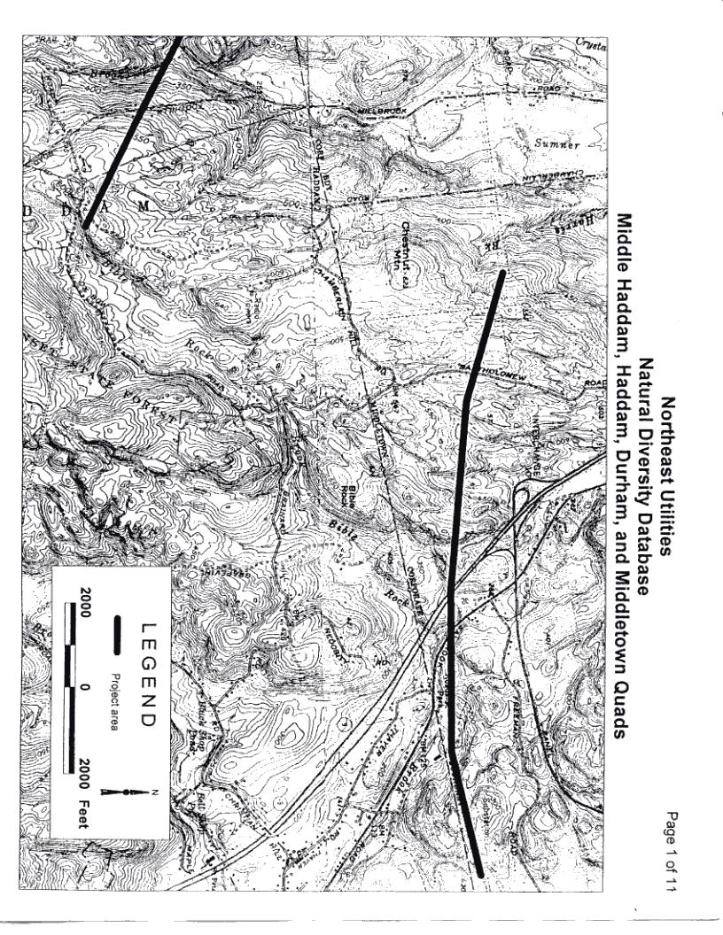
42 2.5 Electric and Magnetic Field Measurements of Overhead Transmission Lines Electric and magnetic fields were also measured at locations along the proposed corridor for the Middletown to Norwalk 345-kV transmission line. Measurements of the magnetic field were made around the perimeter of the Scovill Rock Switching Station, along a profile perpendicular to existing transmission lines along Black Walnut Drive in Durham, along a profile perpendicular to existing transmission lines along Center Road in New Haven (Jewish Community Center), along a profile perpendicular to existing transmission lines near Route 152 (Center Road) in Orange (High Plains Community Center), a perimeter profile around the Milford Driving Range adjacent to existing transmission lines, two profiles perpendicular to existing transmission lines along the proposed route (adjacent to East Side Middle School) in the neighborhood near Pearl Harbor Street in Bridgeport, two profiles perpendicular to existing transmission lines along the proposed route in the vicinity of Madison Avenue in Bridgeport (North Branch Community Center and Library and the John Winthrop School), and around the perimeter of the proposed substation site in Bridgeport near Atlantic and Main Street. Measurements of the electric field were made at locations around the perimeter of the Scovill Rock Switching Station, along a profile perpendicular to existing transmission lines along Black Walnut Drive in Durham, along a profile perpendicular to existing transmission lines along Center Road, at locations perpendicular to the existing transmission lines near Route 152 (Center Road) in Orange and at locations perpendicular to existing transmission lines along the proposed route near Pearl Harbor Street in Bridgeport Scovill Rock Switching Station, Middletown Magnetic and electric fields were measured around the perimeter of Scovill Rock Switching Station. A sketch of the substation and key locations around its perimeter is provided in Figure 3. The magnetic fields are plotted in the upper panel of Figure 4, going clockwise around the station perimeter from the northwest corner. The highest magnetic field measured around the perimeter of the substation was 70 mg and occurred near the northeast corner of the station and was associated with the 345-kV transmission line passing overhead into the station. The electric fields were measured at locations around the perimeter of the station and are plotted in the lower panel of Figure 4. The electric fields were measured at the four corners of the station and at the approximate midpoints. Measurements were also made under the transmission lines entering the station. The highest electric field measured was 1.32 kv/m and occurred along the east side of the station. The field was associated with a 345-kV transmission line passing overhead into the station. 8
43 N Figure Sketch of the Scovill Rock Switching Station perimeter and labeled measurement locations 7 9
44 8.0 Electric Field (kv/m) Electric Field - kv/m Location 1 NW corner of substation Location 2 Substation Driveway Location 4 Transmission Line NE corner of substation Location 5 Transmission Line Location 5.5 Location 6 Transmission Line Location 7 Transmission Line SE corner of substation Distance - ft Location 7.5 Location 8 SW corner of substation Location 9 Transmission Line Location 1 NW corner of substation Location 4 Total RMS Magnetic Field Magnetic Field - mg Location 1 NW corner of substation Location 2 Distribution Lines Substation Driveway Location 3 Substation Building Transmission Line NE corner of substation Location 5 Transmission Line Location 6 Transmission Line Location 7 SE corner of substation Location 8 SW corner of substation Location 9 Transmission Line Location 1 NW corner of substation Distance - ft Figure 4. Plot of the electric and magnetic field around the perimeter of the Scovill Rock Switching Station 10
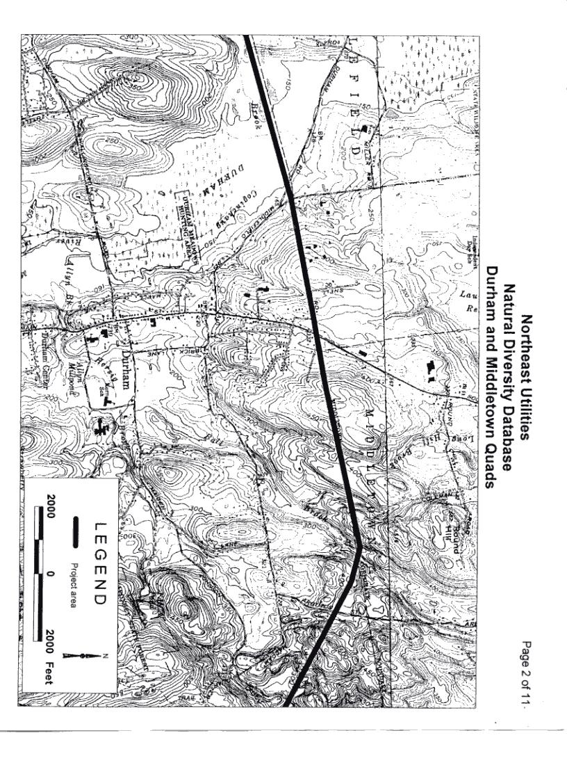
45 2.5.2 Black Walnut Drive, Durham Magnetic field measurements were taken along a profile from south to north perpendicular to the existing 115-kV transmission lines. The highest magnetic field measured was 14.6 mg and occurred under the transmission lines. The magnetic field profile is plotted in Figure 5. Electric field measurements were also made along the profile perpendicular to the transmission lines. The highest electric field measured was 1.45 kv/m and occurred under the transmission lines. The electric field profile is plotted in Figure Total RMS Magnetic Field 175 Magnetic Field - mg Line 1975-A midline Line 1975-B 25 House House Distance - ft Figure 5. Magnetic field profile from south to north for the transmission lines passing over Black Walnut Drive 11
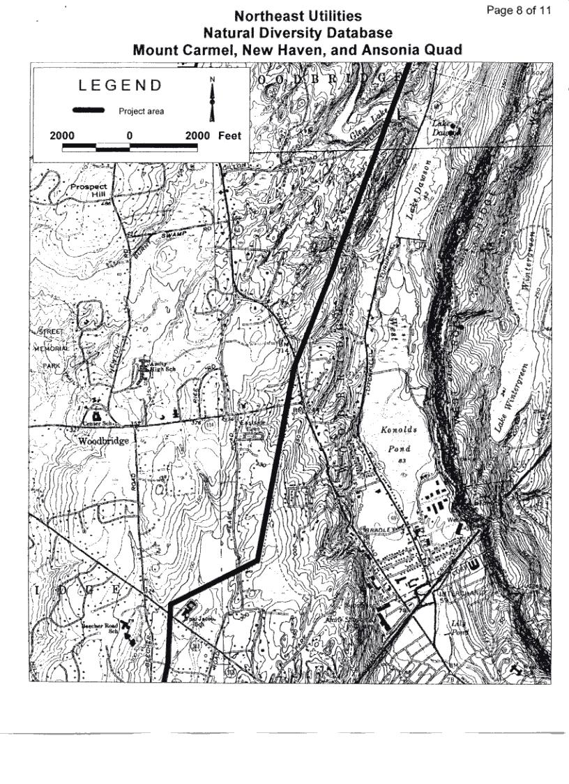
46 8.0 Total RMS Electric Field 7.0 Electric Field - kv/m Line 1975-A Line 1975-B 1.0 House House Distance - ft Figure 6. Electric field profile from south to north for the transmission lines passing over Black Walnut Drive Route 114, Woodbridge (near Jewish Community Center) Magnetic field measurements were taken along a profile from east to west perpendicular to the existing 115-kV transmission lines. The highest magnetic field measured was 18.8 mg and occurred under the transmission lines. The magnetic field profile is plotted in Figure 7. Electric field measurements were also made along the profile perpendicular to the transmission lines. The highest electric field measured was 1.36 kv/m and occurred under the transmission lines. The electric field profile is plotted in Figure 8. 12
47 200 Total RMS Magnetic Field 175 Magnetic Field - mg House Line 1610 Line 1640 Vertical Double Circuit Tower House Distance - ft Figure 7. Magnetic field profile from south to north for the transmission lines passing over Route 114 (Center Road) in Woodbridge 8.0 Total RMS Electric Field Electric Field - kv/m Line 1610 Line 1640 Vertical Double Circuit Tower Distance - ft Figure 8. Electric field profile from south to north for the transmission lines passing over Route 114 (Center Road) in Woodbridge 13
48 2.5.4 Route 152, Orange (High Plains Community Center) Magnetic field measurements were taken along a profile from south to north perpendicular to the existing 115-kV transmission lines. The highest magnetic field measured was 16.2 mg and occurred under the transmission lines. The magnetic field profile is plotted in Figure 9. Electric field measurements were also taken at the location of the highest electric field, which occurred under the double circuit lines, and at the fence line of the playground at its closest approach to the transmission lines. The highest electric field under the transmission lines was 0.90 kv/m. The electric field at the fence line was 0.18 kv/m. 200 Total RMS Magnetic Field 175 Magnetic Field - mg Line 1610 Line 1640 Vertical Double Circuit Tower Building 25 Playground Distance - ft Figure 9. Magnetic field profile from south to north for the transmission lines adjacent to the High Plains Community Center in Orange Milford Driving Range (Proposed Substation Site) Magnetic field measurements were taken along the perimeter of the Milford Driving Range located along Oronoque Road. A sketch of the site is provided in Figure 10. The measurement path started even with the north end of the site at Location 1 in Figure 10 and proceeded in a clockwise direction around the site ( ) back to Oronoque Road and then repeated a section of the path along Oronoque Road from Location 9 to Location 2. The measurement path approached transmission lines adjacent to the site near Location 4. The highest magnetic field measured was 23.6 mg and occurred near the adjacent 115-kV transmission lines. The magnetic field profile is plotted in Figure 11. Electric field measurements were not made due to interference by rain. 14
49 Oronoque Road Oronoque Road N 2 Figure 10. Sketch of the Milford Driving Range along Oronoque Road. 200 Total RMS Magnetic Field Magnetic Field - mg Location 1 NE corner of site along Oronoque Road Location 2 SE corner of site along Oronoque Road Location 3 Location 4 Location 5 Northern Side of Site Location 8 Location 7 Location 6 Location 9 SE corner of site along Oronoque Road Location 2 0 Figure Distance - ft Plot of the magnetic fields around the perimeter of the Milford Driving Range 15
50 2.5.6 Near Pearl Harbor Street, Bridgeport (East Side Middle School) This section of existing ROW is not considered a part of the proposed primary route. Access to the existing transmission line ROW was not possible at this site. Magnetic field measurements were therefore taken along two profile paths from the fence adjacent to the transmission lines to the edge of the nearest building. The first measurement path was perpendicular to the transmission lines at their closest approach to the buildings, which also corresponded to the transmission lines lowest point to ground (midspan). The second profile was perpendicular to the lines at their highest point above ground, which was at the tower. The measurement paths are indicated in the sketch of the site in Figure 12. The magnetic fields along Profile 1 are plotted in Figure 13 and the magnetic fields along Profile 2 are plotted in Figure 14. The highest magnetic field measured along the profiles at this site was at the fence line nearest the existing 115-kV transmission lines and was 7.6 mg. Transmission Lines Fence Profile 1 Profile 2 N School Building Figure 12. Sketch of East Side Middle School site 16
51 200 Total RMS Magnetic Field 175 Magnetic Field - mg Vertical Double Circuit Tower Fence Building Distance - ft Figure 13. Plot of the magnetic fields at East Side Middle School along Profile Total RMS Magnetic Field Magnetic Field - mg Vertical Double Circuit Tower Fence Building Distance - ft Figure 14. Plot of the magnetic fields at East Side Middle School along Profile 2 17
52 Electric field measurements were made along the first profile near the fence line, at the sidewalk in front of the nearest building, and at the edge of the building closest to the fence and 115-kV transmission lines. These locations correspond to 160, 225, and 270 feet referenced to Figures 13 and 14. The electric fields measured at the three locations are listed in Table 2 along with their relative distances from the transmission lines and fence. Table 2. Measured electric field near existing transmission lines Distance from Transmission Lines Distance from Fence Electric Field (kv/m) 160 feet 10 feet feet 75 feet feet 120 feet Madison Avenue, Bridgeport (North Branch Community Center & Library and John Winthrop School) Magnetic field measurements were taken along a profile from south to north perpendicular to the existing transmission lines at the North Branch Community Center and Library and also at the nearby John Winthrop School. The magnetic field measurements taken at the North Branch Community Center are plotted in Figure 15. The highest magnetic field measured was 39 mg and occurred under the 115-kV transmission lines. 200 Total RMS Magnetic Field 175 Magnetic Field - mg Building Vertical Double Circuit Tower Distance - ft Figure 15. Magnetic field measurements in Bridgeport near Madison Avenue at North Branch Community Center 18
53 A magnetic field profile perpendicular to the existing lines was also taken from under the lines to the edge of the nearest building at the site of the John Winthrop School. The magnetic fields are plotted in Figure 16. The highest magnetic field measured along the profile was 68 mg and occurred under the transmission lines. Electric field measurements were not taken due to interference by rain. 200 Total RMS Magnetic Field 175 Magnetic Field - mg Vertical Double Circuit Tower 25 Building Distance - ft Figure 16. Magnetic field measurements in Bridgeport near Madison Avenue at John Winthrop School Atlantic and Main in Bridgeport (Proposed Substation Site) Magnetic field measurements were taken along the perimeter of a potential substation site along Main Street in Bridgeport bounded by Atlantic and Whiting Streets. Bridgeport Energy abuts the site on the fourth side. A sketch of the site is provided in Figure 17. The magnetic fields measured along the perimeter of the site are plotted in Figure 18. The highest magnetic field along the perimeter was 30.5 mg and occurred adjacent to the Bridgeport Energy fence line. 19
54 3 Whiting Street 4 Fence N Main Street Site Power Plant 2 1 Fence Atlantic Street Figure 17. Sketch of the site along Atlantic, Main, and Whiting Streets 200 Total RMS Magnetic Field 175 Magnetic Field - mg SE corner of site along Atlantic Street Corner 1 Corner 2 SW corner of site - Corner of Atlantic & Main Distribution Line Feeder along Main Street Corner 3 NW corner of site - Corner of Main & Whiting NE corner of site along Whiting Stree Corner Distance - ft Figure 18. Magnetic fields along the perimeter of the Bridgeport Substation site 20
55 2.5.9 Norwalk Substation A sketch of the perimeter of the Norwalk Substation is shown in Figure 19. The substation is located on the west side of Route 7 at the junction with Route 123. Electric field measurements were taken around the perimeter of the substation at locations B, E, F, H, J, and L shown in Figure 19. There are trees and brush along the west side of the substation. Route 123 borders the south side of the substation. The east side of the substation borders a southbound exit ramp of Route 7. The north side of the substation is bordered by low brush on the right-of-way of several 115-kV transmission lines for the substation. The electric field measurements are summarized in Table 3. G H IJK F N DE L C B A Figure 19. Sketch of the Norwalk Substation. 21
56 Table 3. Measured electric field perimeter of Norwalk Substation Location Electric Field (kv/m) B: South Side E: West Side (under line) F: North West Side (parallel line) H: North Side J: North East Corner (under lines) L: East Side The magnetic field was also measured around the perimeter of the substation starting at the southeast corner (location C in Figure 19). The plot of the magnetic field around the perimeter of the substation is shown in Figure Magnetic Field - mg A: South-East Corner of Substation Total RMS Magnetic Field C: South-West Corner E: West Side Corner Line <Line> G: North-West Corner Line K: North-East Corner A: South-East Corner of Substation Distance - ft Figure 20. Magnetic field measurements around the perimeter of the Norwalk Substation starting at the substation s southeast corner (location C in Figure 19) 22
57 2.6 Electric and Magnetic Field Calculations of Overhead Transmission Lines When applying for a Certificate of Environmental Compatibility and Public Need (Certificate) before the Connecticut Siting Council (CSC), it is required that the applicant demonstrate that efforts are being taken to manage the electric and magnetic fields associated with those facilities. To this end, the application for the installation of a 345-kV circuit from Middletown to Norwalk, the project has modeled electric and magnetic fields along the rights-of-way (ROWs). For magnetic field calculations the assumed loading on existing and the proposed lines was the 15 GW Case. The fields were calculated for both existing line cross sections along the route and for the cross sections after the proposed 345-kV transmission line. This 15 GW Case conforms to an all New England average annual load of 15 GW that can be expected in the future. This case was developed by NU by modeling an average New England load of approximately 15 GW with representative generator dispatches for this load level. From this load flow modeling, average line loadings in the Connecticut region of interest were determined for the existing systems lines and for the system after the proposed 345-kV line. This provided a realistic comparison of the magnetic field along the proposed route before (without) and after (with) the proposed 345-kV transmission line for similar loading and generation conditions. The magnetic and electric field values associated with the operation of existing and proposed overhead transmission lines at the edges of the right-of-way sections under consideration are shown in Tables 4 and 5, respectively. The location of the sections of the primary route and an alternative route can be identified by the numbers of the sections on Figure 21. Following Figure 21, sketches of each cross section of the route segments are shown with the corresponding profiles of calculated electric and magnetic fields on the facing page. 23
58 Table 4. Edge of right-of-way magnetic field values for existing and proposed overhead line configurations Annual average loading (15 GW) Existing Magnetic Field (mg) Proposed Magnetic Field (mg) Cross Section East/South* ROW West/North** ROW East/South ROW West/North ROW Proposed Primary Overhead Route Alternative Overhead Line Route a b * Identified in NU documentation as left ROW ** Identified in NU documentation as right ROW 24
59 Table 5. Edge of right-of-way electric field values for existing and proposed overhead configurations Existing Electric Field (kv/m) Proposed Electric Field (kv/m) Cross Section East/South*ROW West/North**ROW East/South ROW West/North ROW Proposed Primary Overhead Route Alternative Overhead Line Route a b * Identified in NU documentation as left ROW ** Identified in NU documentation as right ROW 25

60 Figure 21. Proposed 345-kV reinforcements: Middletown S/S to Norwalk S/S on Connecticut circuit map 26
61 Cross Section 1 Figure 22. Cross Section 1 - Scovill Rock Switching Station to Chestnut Junction (Middletown) 27
62 8 7 6 Proposed Electric Field Existing Electric Field Electric Field (kv/m) Proposed ROW Existing ROW ROW Distance (ft) Proposed Magnetic Field Existing Magnetic Field Magnetic Field (mg) Proposed ROW Existing ROW ROW Distance (ft) Figure 23. Electric and magnetic field profiles for Cross Section 1 28
63 Cross Section 2 Figure 24. Cross Section 2 - Oxbow Junction to Beseck 29
64 8 7 Proposed Electric Field 6 Existing Electric Field Electric Field (kv/m) ROW ROW Distance (ft) Proposed Magnetic Field Existing Magnetic Field Magnetic Field (mg) RoW RoW Distance (ft) Figure 25. Electric and magnetic field profiles for Cross Section 2 30
65 Cross Section 3 Figure 26. Cross Section 3 - Black Pond Junction to East Meriden 31
66 8 7 6 Proposed Electric Field Existing Electric Field Electric Field (kv/m) ROW ROW Distance (ft) Proposed Magnetic Field 160 Existing Magnetic Field 140 Magnetic Field (mg) ROW ROW Distance (ft) Figure 27. Electric and magnetic field profiles for Cross Section 3 32
67 Cross Section 4 Figure 28. Cross Section 4 - East Meriden to Beseck 33
68 8 7 Proposed Electric Field 6 Existing Electric Field Electric Field (kv/m) ROW ROW Distance (ft) Proposed Magnetic Field 160 Existing Magnetic Field 140 Magnetic Field (mg) ROW ROW Distance (ft) Figure 29. Electric and magnetic field profiles for Cross Section 4 34
69 Cross Section 5 Figure 30. Cross Section 5 - Beseck to East Wallingford Junction 35
70 8 Proposed Electric Field 7 Existing Electric Field 6 Electric Field (kv/m) ROW ROW Distance (ft) Proposed Magnetic Field 160 Existing Magnetic Field 140 Magnetic Field (mg) ROW ROW Distance (ft) Figure 31. Electric and magnetic field profiles for Cross Section 5 36
71 Cross Section 6 Figure 32. Cross Section 6 - East Wallingford Junction to Wallingford 37
72 8 7 Proposed Electric Field 6 Existing Electric Field Electric Field (kv/m) ROW ROW Distance (ft) Proposed Magnetic Field Existing Magnetic Field 140 Magnetic Field (mg) ROW ROW Distance (ft) Figure 33. Electric and magnetic field profiles for Cross Section 6 38
73 Cross Section 7 Figure 34. Cross Section 7 - Wallingford to Cook Hill Junction 39
74 8 7 Proposed Electric Field Existing Electric Field 6 Electric Field (kv/m) ROW ROW Distance (ft) Proposed Magnetic Field Existing Magnetic Field Magnetic Field (mg) ROW ROW Distance (ft) Figure 35. Electric and magnetic field profiles for Cross Section 7 40
75 Cross Section 8 Figure 36. Cross Section 8 - Cook Hill Junction to East Devon 41
76 8 7 Proposed Electric Field 6 Existing Electric Field Electric Field (kv/m) ROW ROW Distance (ft) Proposed Magnetic Field 160 Existing Magnetic Field 140 Magnetic Field (mg) ROW ROW Distance (ft) Figure 37. Electric and magnetic field profiles for Cross Section 8 42
77 Cross Section 9 Underground Figure 38. Cross Section 9 - East Devon substation to Singer substation to Norwalk substation 43
78 Cross Section 9 Overhead Alternative Figure 39. Cross Section 9 Overhead alternative from Housatonic River Crossing 44
79 8 7 6 Proposed: Electric Field 15 GW Case Existing: Electric Field 15 GW Case Electric Field (kv/m) ROW ROW Distance (ft) 200 Magnetic Field (mg) Proposed: Magnetic Field 15 GW Case Existing: Magnetic Field 15 GW Case ROW ROW Distance (ft) Figure 40. Electric and magnetic field profiles for Cross Section 9 45
80 Cross Section 10 Figure 41. Cross Section 10 Overhead alternative from Housatonic River to West Devon Junction 46
81 8 7 Proposed Electric Field 6 Existing Electric Field Electric Field (kv/m) ROW ROW Distance (ft) Proposed Magnetic Field Existing Magnetic Field 140 Magnetic Field (mg) ROW ROW Distance (ft) Figure 42. Electric and magnetic field profiles for Cross Section 10 47
82 Cross Section 11 Figure 43. Cross Section 11 - Overhead alternative from West Devon Junction to Trumbull Junction 48
83 8 7 Proposed Electric Field 6 Existing Electric Field Electric Field (kv/m) ROW ROW Distance (ft) Proposed Magnetic Field Existing Magnetic Field 140 Magnetic Field (mg) ROW ROW Distance (ft) Figure 44. Electric and magnetic field profiles for Cross Section 11 49
84 Cross Section 11a Figure 45. Cross Section 11a - Overhead alternative from Trumbull Junction to Pequonnock 50
85 8 7 Proposed: Electric Field 15 GW Case 6 Existing: Electric Field 15 GW Case Electric Field (kv/m) ROW ROW Distance (ft) Proposed Magnetic Field 140 Existing Magnetic Field Magnetic Field (mg) ROW ROW Distance (ft) Figure 46. Electric and magnetic field profiles for Cross Section 11a 51
86 Cross Section 11b Figure 47. Cross Section 11b - Overhead alternative from Trumbull Junction to Pequonnock substation (Strafford/Bridgeport) 52
87 8 7 6 Proposed Electric Field Existing Electric Field Electric Field (kv/m) Proposed ROW Existing ROW ROW Distance (ft) Proposed Magnetic Field Existing Magnetic Field Magnetic Field (mg) Proposed ROW Existing ROW ROW Distance (ft) Figure 48. Electric and magnetic field profiles for Cross Section 11b 53
88 Cross Section 12 Figure 49. Cross Section 12 - Overhead alternative from Trumbull Junction to Old Town 54
89 8 7 Proposed Electric Field 6 Existing Electric Field Electric Field (kv/m) ROW Existing ROW Proposed ROW Distance (ft) Proposed Magnetic Field 160 Existing Magnetic Field 140 Magnetic Field (mg) ROW Existing ROW Proposed ROW Distance (ft) Figure 50. Electric and magnetic field profiles for Cross Section 12 55
90 Cross Section 13 Figure 51. Cross Section 13 - Overhead alternative from Old Town substation to Weston substation (Fairfield, Easton, Weston, Bridgeport) 56
91 8 7 Proposed Electric Field 6 Existing Electric Field Electric Field (kv/m) ROW Existing ROW Proposed ROW Distance (ft) Proposed Magnetic Field Existing Magnetic Field Magnetic Field (mg) ROW Existing ROW Proposed ROW Distance (ft) Figure 52. Electric and magnetic field profiles for Cross Section 13 57
92 Cross Section 14 Figure 53. Cross Section 14 Overhead alternative from Weston substation to Norwalk Junction (Weston, Wilton) 58
93 8 7 Proposed Electric Field 6 Existing Electric Field Electric Field (kv/m) ROW Existing ROW Proposed ROW Distance (ft) Proposed Magnetic Field Existing Magnetic Field 140 Magnetic Field (mg) ROW Existing ROW Proposed ROW Distance (ft) Figure 54. Electric and magnetic field profiles for Cross Section 14 59
94 Cross Section 15 Figure 55. Cross Section 15 - Overhead alternative from Norwalk Junction to Norwalk substation (Wilton) 60
95 8 7 Proposed Electric Field 6 Existing Electric Field Electric Field (kv/m) ROW Existing ROW Proposed ROW Distance (ft) Proposed Magnetic Field 160 Existing Magnetic Field 140 Magnetic Field (mg) ROW Existing ROW Proposed ROW Distance (ft) Figure 56. Electric and magnetic field profiles for Cross Section 15 61
96 Cross Section 16 Figure 57. Cross Section 16 - Overhead alternative from Norwalk Junction to Norwalk substation (Wilton) 62
97 8 7 Proposed Electric Field 6 Existing Electric Field Electric Field (kv/m) ROW Existing ROW Proposed ROW Distance (ft) Proposed Magnetic Field 160 Existing Magnetic Field 140 Magnetic Field (mg) ROW Existing ROW Proposed ROW Distance (ft) Figure 58. Electric and magnetic field profiles for Cross Section 16 63
98 Cross Section 17 Figure 59. Cross Section 17 - Overhead alternative from Norwalk Junction to Norwalk substation (Norwalk) 64
99 8 7 Proposed Electric Field 6 Existing Electric Field Electric Field (kv/m) ROW Existing ROW Proposed ROW Distance (ft) Proposed Magnetic Field Existing Magnetic Field 140 Magnetic Field (mg) ROW Existing ROW Proposed ROW Distance (ft) Figure 60. Electric and magnetic field profiles for Cross Section 17 65
100 Cross Section 18 Figure 61. Cross Section 18 - Overhead alternative from Norwalk Junction to Norwalk substation (Norwalk) 66
101 8 7 Proposed Electric Field 6 Existing Electric Field Electric Field (kv/m) ROW Existing ROW Proposed ROW Distance (ft) Proposed Magnetic Field Existing Magnetic Field 140 Magnetic Field (mg) ROW Existing ROW Proposed ROW Distance (ft) Figure 62. Electric and magnetic field profiles for Cross Section 18 67
102 2.7 Underground Transmission Power Delivery Consultants, Inc. (PDC) has calculated the magnetic field produced by the installation of the proposed 345-kV lines in underground high-pressure fluid-filled (HPFF) transmission cables between East Devon and Norwalk (Cross Section 9). The following discussion summarizes their results. Two underground lines, from East Devon to Singer and from Singer to Norwalk, were assumed to be constructed forming a single circuit with high-pressure fluid-filled (HPFF) transmission cables. Only the magnetic field was modeled because the electric field would be shielded by the earth and other materials. The model assumed various total power transfer levels (in mega-voltamperes, MVA) and currents in each 345-kV HPFF circuit and corresponding current in each 345 kv-hpff transmission cable. Note that a circuit consists of two cables per phase i.e. the trench shown in Figure 63 shows a single circuit. The following assumptions were made concerning installation and operating conditions for the 345-kV HPFF underground transmission line lines shown in Figure 63. PAVEMENT AND SUB-BASE IF IN STREETS IN. CONTROLLED BACKFILL 48 IN IN. 24 IN. 28 IN. 48 IN. Figure 63. Cross Section 9 -Trench cross section of 345-kV HPFF cable system The 3000 kcmil copper conductor 345 kv HPFF cables are installed in an 8-inch carbon steel pipe with a wall thickness of ¼ (Schedule 20 pipe). The magnetic properties of the carbon steel pipes vary depending on carbon content as well as the manufacturing process. The magnetic field calculations assume typical magnetic field properties for the carbon steel pipes. The currents flowing in the 345-kV underground 68
103 transmission line will be balanced three-phase currents (i.e. the zero sequence current would be negligible). 2.8 Electric and Magnetic Field Calculations of the HPFF Underground Cable System The steel pipe that contains the 345 kv HPFF cables reduces the magnetic field outside of the pipe because of the following phenomena. Magnetic flux shunting or ducting - it is much easier for the magnetic field to flow in the high permeability steel pipe than it is for it to flow in the soil or air above the ground. Induced eddy currents - the magnetic field produced by the currents in the power cables induces currents in the electrically conducting steel pipe. These induced eddy currents, in turn, produce a magnetic field that opposes the magnetic field produced by the transmission cables. Magnetic flux density calculations were performed using the PTMagField (PTMF) twodimensional magnetic field calculation program for HPFF underground cable systems (Power Delivery Consultants, Inc.). This computer program calculated the magnetic field at a specified distance above ground level by calculating the steel pipe attenuation factor based on the procedures described in an Electric Power Research Institute (EPRI) report, Handbook of Shielding Principles for Power Systems Magnetic Fields and multiplying the unshielded magnetic field times the shielding factor (EPRI, 1994). The magnetic permeability of steel pipe varies with the intensity of the magnetic field produced by the current produced by the power cables. The PTMF program assumes typical magnetic properties for the carbon steel pipe when performing the calculations. The validity of PTMF calculation results have been checked by comparing the program calculation results with field measurements for HPFF transmission cable systems. 3 The calculated magnetic flux density values are the RMS values that would be measured by most three-axis Gauss meters. The calculations assume that balanced three-phase currents are present in the three high voltage cables. The calculated magnetic field, as a function of distance from the centerline of the cable trench, is shown in Figures 64 and 65. Magnetic field values at 0, 25, and 50 feet from the center of the trench are also shown in Tables 6. The above-ground magnetic field values produced by 2750 kcmil HPFF cables would be lower, and would be within two percent of the above-ground magnetic field values produced by the 3000 kcmil HPFF cables modeled by PDC. 3 This evaluation was documented in the "Environmental Impact Statement for the Kamoku - Pukele 138 kv Transmission Line" submitted by the Hawaiian Electric Company to the State of Hawaii Public Utility Commission, and to the Hawaiian Board of Land and Natural Resources, both in The EMF measurements and comparison were done on several HECO 138 kv HPFF lines. 69
104 The carbon steel pipe significantly attenuates the magnetic field produced by the current flowing in the 3000 kcmil cables inside of the pipe. The magnetic field attenuation increases with the magnitude of the current in the HPFF cables because of the nonlinear magnetic properties of the steel pipe. 10 Magnetic Flux Density (mg) Distance From Center Of Cable Trench (Feet) Figure 64. Magnetic field profile of 345-kV East Devon-Singer HPFF underground transmission line 10 Magnetic Flux Density (mg) Distance From Center Of Cable Trench (Feet) Figure 65. Magnetic field profile of 345-kV Singer-Norwalk HPFF underground transmission line 70
105 Table 6. Magnetic field values for 345-kV HPFF cable circuits Line Power Flow* Horizontal Distance = 0 m Magnetic Field (mg) Horizontal Distance = 25 m Horizontal Distance = 50 m East Devon Singer Singer Norwalk * Power flow in mega-volt-amperes (MVA) 2.9 Summary The magnetic field at the edges of the right-of-way of the overhead section of the primary route is increased on some sections and decreased on others. On the primary route, the highest typical magnetic field value from existing lines occurs in Cross Section 5 (23.4 mg) and is increased by 1.0 mg by the addition of the proposed 345-kV line. Lower magnetic field levels occur on other cross sections at average loadings. On the proposed underground section of this route the magnetic field would not exceed 6 mg. On the alternative route (Cross Sections 9-18), the magnetic fields tend to be higher than on the primary route but the addition of the 345-kV line reduces the magnetic field on one or both sides of the right-of-way on 10 of 12 alternative cross sections. The highest magnetic field from the existing lines at the edge of the right-of-way is 38 mg and increased for the proposed conditions by 1.0 mg on Cross Section 11b. The highest electric field for the existing system at the edge of the right-of-way is 1.28 kv/m. The field occurs for Cross Section 1 and decreases to 0.05 kv/m by 200 feet from the edge of the right-of-way. The highest electric field at the edge of the right-of-way with the proposed line is 1.32 kv/m and occurs along Cross Section 1 and decreases to 0.04 kv/m by 200 feet from the edge of the right-of-way. 71
106 3 EMF Research Although electric energy is a beneficial and indispensable component of our society, questions have been raised over the past forty years as to whether exposure to EMF may in some way be adverse. Scientific research to assess whether exposure to electric and magnetic fields at power frequencies can affect human health has been conducted over the past 30 years. Public interest has focused mainly, although not entirely, on the question of cancer and long-term exposures to magnetic fields. This interest arose from studies of human populations in their natural environment (epidemiologic studies of children, adults and workers in jobs presumed to include EMF exposures). This research has been supplemented by studies of cells, tissues and of laboratory animals exposed to EMF. These different approaches epidemiologic and laboratory studies are used to evaluate the potential long-term human health effects of any environmental exposure, including EMF. Epidemiologic studies are valuable because they are conducted in human populations, but they also have limitations because they are not experimental. For example, researchers cannot control the amount of individual exposure to EMF, how exposure occurred over time, the contribution of many different field sources, or individual traits, such as diet and other exposures as can be controlled in laboratory studies. Nonetheless, the search for better methods to assess human exposure has progressed and thereby we have more accurate information on possible links to health. Over the past few years, several groups have reviewed and evaluated reported research findings regarding potential health effects of residential electric and magnetic fields. A broad range of possible biological and health effects have been studied to assess whether elevated exposure to EMF presents a health risk to populations. The following review has been prepared to update the Connecticut Siting Council (CSC) on the status of recent scientific research regarding the potential for health effects of exposure to EMF, and will focus on research published after 1998 highlighting literature published in the last few years. 3.1 Epidemiology Studies of Cancer The question of a link between power lines and childhood cancer is based on the results of earlier studies. The assumption is that the relevant exposure associated with power lines is the magnetic field, rather than the electric field. This assumption rests on the fact that electric fields are shielded from the interior of homes, where people spend the vast majority of their time, by walls and vegetation, while magnetic fields are not shielded. The magnetic field in the vicinity of a power line is the result of a flow of current. Higher currents result in higher levels of magnetic fields. The majority of epidemiology studies have largely focused on magnetic rather than electric fields, although there is a small body of literature that has evaluated the latter. Epidemiologic studies report results in the form of statistical associations. The term statistical association is used to describe the tendency of two things to be linked or to vary in the same way, such as higher level of exposure and increased occurrence of disease. However, statistical associations are not automatically an indication of cause and effect, because the interpretation of 72
107 numerical information depends on the context, including (for example) the nature of what is being studied, the source of the data, how the data were collected, and the size of the study. In addition, both epidemiology data in humans and laboratory data in animals or cells are used to assess the possibility of human health effects Studies of Children Studies of Magnetic Field Exposures Prior to 1998, epidemiologic studies of cancer reported that children who developed leukemia were more likely to live near power lines that produced higher magnetic fields than other power lines. The term power line refers to both transmission lines and neighborhood distribution lines. In many of these studies, the power lines the children lived near were more often distribution lines. The exposure to EMF was based on an indirect, and therefore imprecise, method for estimating magnetic field exposure from power lines called the wiring code. (Wire codes are a surrogate for magnetic field exposure, based on the diameter or thickness of the wire and its distance from the residence. They are not based on actual magnetic field levels.) Subsequent studies have included important improvements to obtain more reliable results to aid in resolving the differences in results among studies. These improvements include more extensive EMF measurements in the homes, measurements taken by a personal exposure monitor, a larger study population, or a shorter interval between the time the disease was diagnosed and the time exposure was assessed. Major recent studies are summarized below: A study conducted in Ontario, Canada compared the estimated magnetic field exposure of 201 children who had cancer to that of a similar group of children without cancer (Green et al, 1999a). No increased risk estimates were found for exposure assessed as average magnetic fields in the bedroom or the interior, or any of the three methods of estimating exposure from wire configuration codes. An even smaller group of 88 children with leukemia and their controls wore personal monitors to measure magnetic fields (Green et al, 1999b). Associations with magnetic fields were reported in some of the analyses, but most of the risk estimates had a broad margin or error and major methodological problems in the study preclude any clear interpretation of the findings. A study from British Columbia, Canada included 462 children who had been diagnosed with leukemia and an equal number of children without leukemia for comparison (McBride et al, 1999). Magnetic field exposure was assessed for each of the children in several ways; regardless of the method used to estimate magnetic field exposure, the magnetic field exposure of children who had leukemia was not greater than the children in the comparison group. In December 1999, the United Kingdom Childhood Cancer Study (UKCCS) investigators reported the results of a well-designed study of EMF and childhood cancer (UKCCS, 1999). Exposure was assessed by magnetic field measurements in the home (bedroom and family room) and school, and summarized for each individual by averaging these over time. The children 73
108 who had cancer of the central nervous system, other cancers, or total malignant disease had no different exposure to magnetic fields than that experienced by controls (children who had no disease). Those who had acute lymphocytic leukemia (ALL) also had exposures similar to the controls for the three lower exposure levels (less than 4 mg). However, slightly more cases than controls were found in the highest exposure category where fields were categorized as greater than 4 mg. These results indicated a weak association with magnetic fields above 4 mg that was likely due to chance. The UKCCS investigators had only obtained magnetic field measurements on a portion of the cases in their study. To obtain additional information, they used a method to assess exposure to magnetic fields without entering homes (UKCCS, 2000) and were able to analyze 50% more subjects (a total of 3380 all cancer cases and 3390 controls). For all these children they measured distances to power lines and substations. This information was used to calculate the magnetic field from these external field sources, based on power line characteristics related to production of magnetic fields. The results of the second UKCCS study showed no association with leukemia for magnetic fields calculated to be 4 mg or greater at the residence, in contrast to the weak association reported for measured fields 4 mg or greater in the first report (UKCCS, 1999). A study from Germany included 502 children with leukemia and 1,289 control children (Schuz et al, 2001). EMF in Europe changes direction and intensity 50 times, or cycles, per second (50 Hz). Measurements of magnetic field intensity (50 Hz) were taken for 24 hours in the child s bedroom. The results were calculated for daytime or nighttime levels in the bedroom, rather than the child s overall 24-hour exposure. They reported a positive association between mean nighttime magnetic field levels and leukemia for the highest exposed group (4 mg or higher; 9 cases). However, magnetic field levels measured in the bedroom represent a mixture of sources from household appliances, powerlines, etc., and cannot link magnetic field levels directly to any specific source; the authors note, fewer than one-third of all stronger magnetic fields were caused by high-voltage powerlines Several aspects of the study detract from the validity of the results. The estimate included a broad margin of error because only a small number of the cases were exposed at the higher levels, and many eligible cases and controls did not participate, which means that the responders may not represent the population and results could be biased. Another concern is that magnetic field measurements were taken in 1997, a long time after the relevant exposure period for cases that were diagnosed in Recently, researchers reanalyzed the data from previous epidemiology studies of magnetic fields and childhood leukemia that met specified criteria (Ahlbom et al, 2000; Greenland et al, 2000). In each of these analyses, the researchers pooled the data on individuals from each of the studies, creating a study with a much larger number of subjects and therefore greater statistical power than any single study. In addition, pooling the individual data is preferable to other types 74
109 of meta-analyses in which the results from several studies are combined, using the grouped data reported in the published studies. These meta-analyses focused on studies that assessed exposure to magnetic fields using 24-hour measurements or calculations based on the characteristics of the power lines and current load. Both Greenland et al and Ahlbom et al used exposures less than 1 mg as a reference category, which is roughly the average level reported in a survey of American homes (Zaffenella, 1993). Ahlbom et al combined nine studies, and Greenland et al used 12 studies of magnetic fields, eight of which were the same as used by Ahlbom. Both studies included ALL as well as other forms of leukemia. The Greenland et al study did not include results from the recent, very large study from the United Kingdom (UKCCS, 1999, 2000). The statistical results of these analyses can be summarized as follows: The pooled analyses provided no indication that wire codes are more strongly associated with leukemia than measured magnetic fields. Pooling these data corroborates an absence of an association between childhood leukemia and magnetic fields for exposures below 3 mg. Pooling these data results in a statistical association with leukemia for exposures greater than 3-4 mg. Average magnetic fields above 3 mg in residences are estimated to be rather rare, about 3 % in the US. The authors are appropriately cautious in the interpretation of their analyses and they clearly identify the limitations in their evaluation of the original studies. One limitation is that there are too few cases at higher environmental levels to adequately characterize a relationship between magnetic fields and leukemia. Another limitation is the uncertainty related to pooling estimates of exposure obtained by different methods from studies of diverse design without evidence that all of the estimates are comparable. The authors also expressed concern about the possibility of systematic error in the selection of control populations. Greenland et al (2000) comments, In light of the above problems, the inconclusiveness of the results seems inescapable; resolution will have to await considerably more data on high electric and magneticfield exposures, childhood leukemia, and possible bias sources. It is important to note that the information from these pooled analyses is not new because, for many years, epidemiologic studies and reviews have suggested an association between magnetic fields and childhood leukemia. What is new is that an association of magnetic fields with childhood leukemia is not present for exposures below about 3 to 4 mg. Previous reviews based on fewer studies had suggested an association at levels as low as 2 mg. Wartenberg (2001) published a different type of meta-analysis of data from epidemiologic studies of childhood leukemia studies. He used 19 studies overall, including the UKCCS (1999) study which included over 1,000 cases of childhood leukemia, after excluding seven studies that had insufficient data on individuals or deficiencies in the exposure assessment data. This metaanalysis did not have the advantage of obtaining and pooling the data on all of the individuals in the studies, unlike those published before it (Ahlbom et al, 2000; Greenland et al, 2000). Rather than individual data each of the individual studies, Wartenberg used an approach based on the results from several published studies, which were reported as grouped data. No statistically consistent results of the meta-analysis were found. He reported a weak association for a) proximity to electrical facilities based on wire codes or distance, and b) magnetic-field 75
110 level over 2 mg, based on either calculations from wiring and loading characteristics (if available) or on spot magnetic-field measurements. There are several limitations of the Wartenberg meta-analysis. The author concludes that the analysis supports an association, however, little scientifically significant odds ratios were found. In the discussion section of the paper, Wartenberg states, limitations due to design, confounding, and other biases may suggest alternative interpretations (p. 100). The results of this meta-analysis are not directly comparable to previous ones regarding fields of 3 or 4 mg because the analysis was not based on individual data, and because the exposure cut-points used for grouping data for the analysis differed from the previous analyses (2 mg vs. 3 or 4 mg). Scientifically, because of the heterogeneity of the studies included in the analyses, metaanalyses remain a controversial tool for summarizing these study findings. Studies of Electric Field Exposures Assessing electric field exposures is more difficult than magnetic field exposures because electric fields are easily blocked by objects. A few epidemiology studies of children, however, have focused on exposures to electric fields from transmission lines and electrical appliances. Childhood cancer was not found to be associated with electric fields whether exposure was estimated with spot measurements (Savitz, 1988; London, 1991), mean measurements (Coghill et al, 1996; Dockerty et al, 1998), or personal monitoring (McBride et al, 1999; Green et al, 1999a) as electric field exposure measurements. The UKCCS recently re-evaluated a subset of subjects from their 2000 study in which magnetic and electric field exposures were measured simultaneously at the residence. Measurements with two readings with validity checks were recorded for 549 subjects (273 cases, 276 controls). No elevations in risk were found in any electric field exposure group for total leukemia, ALL, central nervous system cancers, other malignancies, or all malignancies. IARC (2002) has evaluated the body of evidence of electric field exposures in children and conclude that there is inadequate evidence in humans for the carcinogenicity of extremely lowfrequency electric fields. They state: Numerous studies of the relationship between electrical appliance use and various childhood cancers have been published. In general, these studies provide no discernable pattern of increased risks associated with increased duration and frequency of use of appliances. Studies of parental occupational exposure to ELF electric and magnetic fields in the preconceptional period or during gestation are methodologically weak and the results are not consistent (IARC, 2002; p. 333) Studies of Adults Studies of Residential Exposures Studies of adults in their residences have generally not supported the idea that overall cancer, or any particular type of cancer, is increased by EMF exposure (e.g., Verkasalo et al, 1996). 76
111 Several studies have reported associations for certain types of cancer, such as brain cancer or leukemia in adults but results have not been consistent across studies (Feychting and Ahlbom, 1994; Li et al, 1997). Contradictory results among studies that are considered of similar quality and strength argue against a conclusion that the association is cause and effect. Larger studies with more detailed and individual exposure assessments are weighed more heavily in the scientific assessment of risk, as seen in the following examples: A large study of 492 adult cases of brain cancer in California included measurements taken in the home, and at the front door, and considered the types of power line wiring (Wrensch et al, 1999). The authors report no evidence of increased risk with higher exposures, no association with type of power line, and no link with levels measured at the front door. A study of residential exposures to magnetic fields in Sweden found no association with breast cancer in the women who were studied, although an assessment of the younger women (pre-menopausal) provided some weak evidence for a link (Feychting et al, 1998). Subsequent studies provide important additional evidence. Electric blankets are assumed to be one of the strongest sources of EMF exposure in the home, yet three studies found no evidence for an increased risk of breast cancer in those who used electric blankets (Gammon et al, 1998; Zheng et al, 2000; Laden et al, 2000). The latter is the largest; in a cohort of over 120,000 female nurses, data was obtained on known risk factors for breast cancer as well as electric blanket use. Women who developed breast cancer reported no difference in total use of electric blankets, use in recent years, or use many years in the past. Studies of Occupational Exposures The exploration of occupational exposures of EMF and adult cancers began with a report of increased leukemia in electrical workers (Milham, 1982). Milham developed a list of occupations that he presumed would include high exposure to electromagnetic fields. The occupations categorized as electrical workers were used in numerous subsequent studies, despite the absence of any systematic measurements of electric or magnetic fields for any job descriptions. Based on associations reported in studies of electrical workers, EMF was equated with power frequency exposure, i.e., Hz, in both scientific publications and media reports. No systematic measurements for these jobs were available for many years. These studies reported statistical associations between electrical workers and leukemia or brain cancer, but not with all cancers combined or more common cancer types. Better exposure assessment needed to understand these results. Exposure assessment was improved by focusing on cohorts of workers in the electric utility industry, a workplace presumed to have relatively high exposure to power frequency fields compared to residential exposures. Estimates of exposures were developed from personal dosimeters worn by workers in various jobs in the industry. Industry records provided information on all of the jobs held by these workers while they were employed. Several researchers designed cancer studies in which cumulative exposure was estimated from the measurements in the utility workplace environment (Sahl et al, 1993; Savitz and Loomis, 1995; 77
112 Feychting et al, 1997; Johansen et al, 1998). The large populations and the ability to isolate workers with high levels of cumulative exposure were design factors that increased the ability to detect potential risk. However, these studies did not show stronger, more consistent associations with brain cancer or leukemia than previous studies. No increase in overall cancer was found in these workers. The occupational studies published through 1998 are described in the IARC review (2002). Subsequently, a case-control study of men in eight Canadian provinces estimated their occupational exposure to magnetic fields and risks of different types of brain cancer. The study reported an association between one type of brain cancer and an estimate of occupational magnetic field exposure. However, no increased risk for any other type of brain cancer was found. The authors caution that the study had a small number of cases of each cancer type and that the magnetic field exposures were indirectly estimated (Villeneuve et al, 2002). 3.2 Laboratory Studies of Cancer Studies in which laboratory animals receive high exposures provide an important basis for evaluating the safety of chemicals and medicine. Laboratory studies complement epidemiologic studies of people because while people are the species of interest, there are large variations in heredity, diet, and other health-related exposures. These variables can be better controlled or eliminated in studies of laboratory animals than in humans. The assessment of EMF and health, as for any other exposure, includes chronic, long-term studies in animals (in vivo studies), as well as studies of cancer-related changes in genes or other cellular processes observed in isolated cells and tissues in the laboratory (in vitro studies). In several recent studies, rats and mice were exposed to magnetic fields for almost their entire lifetime. In these studies, neither overall cancer occurrence, nor the occurrence of specific types of cancer such as brain cancer, breast cancer or leukemia were different in the exposed animals from those of unexposed, control animals, even at the highest exposure levels. Studies of tumor formation, or of tumor promotion in animals have not shown that magnetic fields promote the growth of cancer in general, or breast or brain cancer in particular (e.g., Anderson et al, 1999; DiGiovanni et al, 1999; Boorman et al, 1999a; Mandeville et al, 2000), although there have been suggestive findings from one other laboratory. In a study of a different design, researchers used an animal model for progression of leukemia that involves transplanting leukemia cells into young rats prior to exposure (Morris et al, 1999; Anderson et al, 2001). In these studies at the same laboratory, exposure to magnetic fields did not alter or increase the speed in which the cells developed into leukemia for continuous or intermittent exposure. The combined animal bioassay results do not provide evidence that magnetic fields cause, enhance, or promote the development of leukemia and lymphoma, or mammary cancer (e.g., Boorman et al, 1999a,b; McCormick et al, 1999; Boorman et al, 2000 a,b; Anderson et al, 2001). Although the results of the RAPID Program were described in some detail in the NIEHS reports (NIEHS, 1998), many of the studies had not been published in the peer-reviewed literature. The RAPID research program included studies of four biological effects, each of which had been 78
113 observed in only one laboratory. These effects are as follows: effects on gene expression, increased intracellular calcium in a human cell line, proliferation of cell colonies on agar, and increased activity of the enzyme ornithine decarboylase (ODC). Some scientists have suggested that these biological responses are signs of possible adverse health effects of EMF. It is standard scientific procedure to attempt to replicate results in other laboratories, because artifacts and investigator error can occur in scientific investigations. Replications, often using more experiments or more rigorous protocols, help to ensure objectivity and validity. Attempts at replication can substantiate and strengthen an observation, or they may discover the underlying reason for the observed response. Studies in the RAPID program reported no consistent biological effects of EMF exposure on (1) gene expression, (2) intracellular calcium concentration, (3) growth of cell colonies on agar, or (4) ODC activity (Sisken and DeRemer, 2000; Boorman et al, 2000b). Loberg et al (2000) and Balcer-Kubiczek et al (2000) studied the expression of hundreds of cancer-related genes in human mammary or leukemia cell lines. They found no increase in gene expression with increased intensity of magnetic fields. To test the experimental procedure, they used X-rays and treatments known to affect the genes. These are known as positive controls and, as expected, caused gene expression in exposed cells. 3.3 Summary of Research on Cancer The results of the latest epidemiologic studies of childhood cancer do not provide sufficient or convincing evidence to support the hypothesis that exposure to electric or magnetic fields or power lines near the home are a cause of leukemia in children. The larger or more reliable residential studies do not support the idea that fields in the residence contribute to the risk of cancer in adults. Although they provide evidence most relevant to humans, the results of epidemiologic studies may include uncertainties because they are observational rather than experimental. For this reason, laboratory studies can provide important complementary information. The larger and more thorough animal studies that exposed animals for EMF for their entire lifespan show no increases in cancer or other adverse health effects in exposed animals. 3.4 Research Related to Reproduction Several epidemiology studies have examined effects on pregnancy, including miscarriages 4 in relation to exposures to magnetic fields. Previous large epidemiology studies reported no association with birth weight or fetal growth retardation after exposure to sources of relatively strong magnetic fields, such as electric blankets, or sources of typically weaker magnetic fields such as power lines (Bracken et al, 1995; Belanger et al, 1998; Lee et al, 2000). Belanger et al (1998) assessed the magnetic field exposure of 2967 women during their pregnancy in two different ways. Exposure to magnetic fields from electric bed-heating (electric blankets and water beds), sources of 4 The medical term for miscarriage is spontaneous abortion. 79
114 relatively strong magnetic fields was estimated from the women s responses in an interview. In general, electric bed heating results in higher magnetic field exposures than those from residential fields. Wire codes were assessed for each woman to estimate the contribution of transmission and distribution lines within 150 feet of the house to exposure in the residence. No evidence was found for an association between miscarriage and exposure to magnetic fields from living in a residence with high wire code, or from using electric blankets or a waterbed around the time of conception or during pregnancy (at time of interview). There was no indication of an increased risk with daily exposure, or longer hours, or using the electric bed at the high setting. The data collected in a large, prospective, epidemiology study by Belanger et al (1998) had been analyzed previously for other endpoints. The results of this analysis also showed no evidence of reduced birth weight in the infants, or slower fetal growth after exposure to sources of relatively strong magnetic fields, such as electric blankets, or sources of typically weaker magnetic fields such as power lines (Bracken et al, 1995). Another study also focused on exposures from electric bed heating (electric blankets, heated waterbeds and mattress pads) (Lee et al, 2000). The researchers assessed the women s exposure prior to birth and included information to control for potential confounding factors. This study had a large number of cases and high participation rates. Miscarriage rates were lower among users of electric bed heating. Two recent studies of EMF and miscarriage reported a positive association between miscarriage and exposure to high, or instantaneous, peak magnetic fields (Li et al, 2002; Lee et al, 2002). However, no reliable associations were found with higher average magnetic field levels during the day, the typical way of assessing exposure. In these studies, women wore magnetic-field monitors for a 24-hour period to assess exposure. Magnetic field levels similar to the peak levels are routinely found near electric devices such as hairdryers, photocopy machines, electric tools, shavers, in or near electric trains, and under some types of power lines. Neither study found that miscarriage was associated with characteristics of power lines outside the home, which area associated with high magnetic fields. There are several possible issues to be considered in assessing whether these statistical associations with the maximum, or peak, exposure during the day are due to cause-and-effect. First, the studies include possible biases. For example, each of the studies had a low response rate, which means that the study groups may not be comparable because those who participate may differ from those who decline (selection bias). Second, these studies found no reliable association with higher daily average exposure, that is, the average of the measurements recorded throughout the day. Third, despite years of research, there is no biological basis to indicate that EMF increases the risk of miscarriage (Savitz, 2002) Laboratory Research of Reproductive Effects Large studies of laboratory animals exposed to pure 60-Hz magnetic fields have shown no increase in birth defects, no multigenerational effects, and no changes that would indicate an 80
115 increase in miscarriage or loss of fertility (e.g., Ryan et al, 1999; Ryan et al, 2000; Ohnishi et al, 2002). Exposed and unexposed litters were the same in the amount of fetal loss and the number and type of birth defects, indicating no reproductive effect of magnetic fields. In summary, the recent evidence from laboratory studies provides no indication that exposure to power-frequency EMF has an adverse effect on reproduction, pregnancy, or growth and development of the embryo. The epidemiology evidence from recent studies suggests that miscarriage may be linked to high peak field levels, not averages. However, the lack of biological support and the presence of possible sources of bias counter the idea that the statistical association is causal. 3.5 Research Related to Neurobiological Effects and Neurological Diseases Studies of mental health and behavior reflect the functioning of neurobiological systems. Epidemiologic studies have examined the relationship between EMF and diseases of the central nervous system, and between EMF and mental health. One hypothesis that has been proposed to explain how EMF might affect health suggests that exposure to electric or magnetic fields decreases the body s production of the hormone melatonin. Because melatonin is related to the body s daily rhythms, depression and effects on mood and the nervous system have been hypothesized. On this basis, scientists studied occupational magnetic field exposure in relation to suicide (van Wijngaarden et al, 2000). The NIEHS reviewed data through 1998 and concluded that there was inadequate evidence for linking occupational or residential EMF exposure to suicide or depression. In addition, studies in humans and animals, including those published after the NIEHS report, have not supported the conjecture that EMF exposure suppresses melatonin secretion in men or women (e.g., Löscher et al, 1998; Davis et al, 2002). Research has also addressed neurodegenerative diseases such as Parkinson s and Alzheimer s Diseases without any evidence showing a link between exposure to EMF and these diseases (NRPB, 2001a). 3.6 Power Line Electric Fields and Airborne Particles and Ions Researchers from a university in England have suggested that the AC electric fields from power lines might affect health indirectly, by interacting with the electrical charges on certain airborne particles in the air. They hypothesize that more particles will be deposited on the skin by a strong electric field, or in the lung by charges on particles (Henshaw et al, 1996; Fews et al, 1999 a,b; Fews et al, 2002). If this interaction did occur, i.e., the airborne particles were charged to increase deposition on skin and in lungs to a sufficient degree, then they further hypothesize that human exposure to various airborne particles and disease might increase. These hypotheses remain highly speculative. Other scientists have found their assumptions unconvincing, and recognize data gaps in the steps of the hypotheses. IARC has stated that the relevance of these suggestions to health has not been established (IARC, 2002). Similar conclusions have been reached in other evaluations of this hypothesis (NRPB, 2001b; HCN, 2001). However, questions about effects of these charged particles have been raised in the media. 81
116 In their laboratory, Henshaw and colleagues have developed models to test the physical assumptions that are the first step of their hypotheses, that electric fields can change the behavior of particulates in the air. For example, they measured the deposition of radon daughter 5 particles on metal plates, in the presence of electric fields at intensities found under or near to power lines. Under these conditions, deposition of products on surfaces was slightly increased, which implies that the deposition might also occur on other surfaces, such as the skin. What they have not tested is the most speculative and unconvincing part of the hypothesis, that such changes in the deposition rate of particles lead to an important increase in human exposure, and also that the increased skin exposure would be sufficient to impact human health, in this case increase skin cancer. Given the small change anticipated, the effect of wind to disperse particles, and the limited time that people spend outdoors directly under high-voltage power lines, the assumption of health effects is unsupported (Swanson and Jeffers, 2000). Another hypothesis described by these researchers is that AC electric fields at the surface of power line conductors leads to increased charges on particles and thereby increase the likelihood that inhaled particles, including radon daughters, will be deposited on surfaces inside the lung or airways, even at considerable distances from the line. Air contains particles of various sizes, including aerosols 6 from emissions from cars and trucks, manufacturing, and natural sources such as radon from soil, rock, and building materials. If, as hypothesized, charges on the aerosol particles increased the deposition in the lungs when inhaled over long periods of time, this could in theory lead to increases in respiratory disease as well as possibly other diseases. Although aspects of these hypotheses have a physical basis, other steps of the hypothesis are highly speculative, and the conclusion that power lines could substantially affect human exposure to airborne particles or lead to adverse health effects is unwarranted (Swanson and Jeffers, 2000). These speculations are not supported by the epidemiologic research, which does not provide substantial evidence for an effect of power lines on lung cancer. In addition, radon has been linked to lung cancer, but not to leukemia (IARC, 2001). The National Radiological Protection Board (NRPB) of Great Britain considered the hypotheses and data published by Fews et al regarding aerosol deposition by electric fields (1999a) and exposure to corona ions from power lines (1999b). The report concluded: The physical principles for enhanced aerosol deposition in large electric fields are well understood. However, it has not been demonstrated that any such enhanced deposition will increase human exposure in a way that will result in adverse health effects to the general public (NRPB, 2001b p. 23). 3.7 Reviews of EMF Research by Scientific Panels Numerous organizations responsible for health decisions, including national and international organizations have convened groups of scientists to review the body of EMF research. These 5 Radon daughters refer to the radioactive decay products of radon ( 222 Rn). 6 An aerosol is a relatively stable suspension of solid particles or liquid droplets in a gaseous medium. 82
117 expert groups, including the National Institute of Environmental Health Sciences (NIEHS), the International Agency for Research on Cancer (IARC), the National Radiological Protection Board of Great Britain (NRPB), the Health Council of the Netherlands (HCN), and the Neutra et al., have included many of scientists with diverse skills that reflect the different research approaches required to answer questions about health. The most recent review is from the IARC, published in International Agency for Research in Cancer (IARC) The International Agency for Research on Cancer sponsored a review of EMF and health research by a Working Group of scientific experts from 10 countries. The Working Group concluded that the epidemiologic studies do not provide support for an association between childhood leukemia and residential magnetic fields at intensities less than 4 mg. Overall, EMF were evaluated as possibly carcinogenic to humans (Group 2B), based on the statistical association of higher-level residential magnetic fields and increased risk for childhood leukemia. IARC reviewers also evaluated the animal data and concluded that it was inadequate to support a risk for cancer. Coffee is also classified as Group 2B. Their summary states that the EMF data does not merit the category carcinogenic to humans or the category probably carcinogenic to humans, nor did they find that the agent is probably not carcinogenic to humans. Many hypotheses have been suggested to explain possible carcinogenic effects of electric or magnetic fields; however, no scientific explanation for carcinogenicity of EMF fields has been established (IARC, 2002) Neutra et al. In response to a request from the California Public Utilities Commission, three scientists at the California Department of Health Services (CDHS) were asked to review and evaluate the scientific research regarding EMF and health. Two epidemiologists and a physicist from the department s EMF Program, fewer than any review group, were assigned to this task. The scientists completed their fourth and final draft in June 2002 (Neutra et al., 2002). This review has gotten considerable attention and therefore is described below. The scientists used two different approaches to conduct their evaluation. One was characterized as following the IARC approach, described above, in which reviewers summarize the quality of evidence. However, unlike IARC, which weighs both epidemiology and experimental data, the scientists gave little weight to the experimental data. The other approach was a set of guidelines developed by the California EMF Program, which calls for each scientist to express a degree of confidence that the disease may be caused by high EMF exposures. For example, a scientist who was certain, or thought it highly probable, that observed statistical associations indicated causality would present their judgment as virtually certain that they [EMF] increase the risk to some degree. The scientists evaluated data regarding approximately a dozen health conditions and concluded that the epidemiologic data provided little support for an association of EMF with nine of the conditions. For the rest, they expressed the belief that EMFs can cause some degree of increased risk of childhood leukemia, adult brain cancer, Lou Gehrig s disease, and 83
118 miscarriage. Their median confidence ratings for these conditions, however, were not high enough to indicate any strong certainty or high probability that EMF was a cause of these conditions. As noted previously, they state, there is a chance that EMFs have no effect at all (Neutra et al., 2001). For all other health effects, including breast cancer, heart disease, Alzheimer s Disease, depression, increased risk of suicide, and adult leukemia, the CDHS reviewers do not believe that there is evidence that exposures to EMF increases the risk of developing any of these illnesses. They agree that EMF is not a universal carcinogen (Neutra et al., 2002) Conclusions of Other National and International Organizations The conclusions from several other national and international organizations including the National Institute of Environmental Health Sciences, the National Radiological Protection Board of Great Britain (NRPB), and the Health Council of the Netherlands (HCN) are listed in Table 7. The conclusions from the report prepared by the NRPB s Advisory Group on Non- Ionising Radiation on Extremely Low Frequency (ELF) electromagnetic fields and the risk of cancer are consistent with previous reviews as are those from the Health Council of the Netherlands (HCN, 2001). Scientists from the IARC, the NIEHS, the NRPB, and the HCN agree that there is little evidence suggesting that EMF is associated with adverse health effects, including most forms of adult and childhood cancer, heart disease, Alzheimer s disease, depression, and reproductive effects. All organizations believe that there is some evidence that EMF at high exposures is linked to childhood leukemia, agree that the laboratory data does not support a link between EMF and any adverse health effect, including leukemia, and have not concluded that EMF is, in fact, the cause of any disease. None of these organizations have recommended exposure limits or required measures to reduce exposures. 84
119 Table 7. Conclusions of international agencies and scientific groups Agency or Scientific Group National Institute of Environmental Health Sciences (NIEHS, 1998; NIEHS, 1999) International Agency for Research on Cancer (IARC, 2002) National Radiological Protection Board of Great Britain (NRPB, 2001b) Health Council of the Netherlands (HCN, 2001) Conclusions The scientific evidence suggesting that ELF-EMF exposures pose any health risk is weak. The strongest evidence for health effects comes from associations observed in human populations with two forms of cancer: childhood leukemia and chronic lymphocytic leukemia in occupationally exposed adults... In contrast, the mechanistic studies and animal toxicology literature fail to demonstrate any consistent pattern... No indication of increased leukemias in experimental animals has been observed... The lack of consistent, positive findings in animal or mechanistic studies weakens the belief that this association is actually due to ELF- EMF, but it cannot completely discount the epidemiological findings... The NIEHS does not believe that other cancers or other non-cancer health outcomes provide sufficient evidence of a risk to currently warrant concern. Studies in experimental animals have not shown a consistent carcinogenic or cocarcinogenic effects of exposures to ELF [extremely low frequency] magnetic fields, and no scientific explanation has been established for the observed association of increased childhood leukaemia risk with increasing residential ELF magnetic field exposure. IARC categorized EMF as a possible carcinogen for exposures at high levels, based on the meta-analysis of studies of statistical links with childhood leukemia at levels above 3-4 mg. Laboratory experiments have provided no good evidence that extremely low frequency [ELF] electromagnetic fields are capable of producing cancer, nor do human epidemiological studies suggests that they cause cancer in general. There is, however, some epidemiological evidence that prolonged exposure to higher levels of power frequency magnetic fields is associated with a small risk of leukemia in children. In practice, such levels of exposure are seldom encountered by the general public in the UK [or in the US]. Because the association is only weak and without a reasonable biological explanation, it is not unlikely that it [an association between ELF exposure and childhood leukemia] could also be explained by chance The committee therefore sees no reason to modify its earlier conclusion that the association is not likely to be indicative of a causal relationship. 85
120 4 Overall Project EMF Assessment The proposed modifications to the existing substations and the Middletown-Milford right-ofway will affect levels of electric and magnetic fields, with the greatest effect within the boundaries of the right-of-way. Outside the boundaries of substation sites and the right-of-way, the effect of the project on EMF levels will be limited because of the design and the location of the substations and the proposal to expand the right-of-way in a few sections. Despite the addition of a 345-kV transmission line to the existing right-of-way, the electric field will be lower along one or both right-of-way edges for 4 of the 8 sections of the primary route (Cross Sections 1-8, Table 5). Similarly, the magnetic field will be lower along one or both right-ofway edges for 3 of 8 sections of the primary route (Cross Sections 1-8, Table 4). On the alternative route (Cross Sections 9-18), the magnetic fields tend to be higher than on the primary route but the addition of the 345-kV line reduces the magnetic field on one or both sides of the right-of-way on 10 of 12 alternative cross sections. At distances greater than approximately 100 feet from edges of the proposed right-of-way, the differences between the levels of fields produced by the lines in existing and future configurations become smaller. In addition to meeting the requirements of the National Electrical Safety Code (IEEE, 2002) and of The Connecticut Light and Power Company and The United Illuminating Company, the project has followed the guidelines embodied in the Connecticut Siting Council s Electric and Magnetic Field Best Management Practices. As called for by these guidelines, this report contains a project-specific assessment of EMF including baseline, pre-construction measurements of EMF. The design and location of the new facilities also minimizes potential EMF exposure. A final component of the Electric and Magnetic Field Best Management Practices is the recognition of completed and ongoing research on EMF. The review and evaluation of this research summarized in this report does not provide evidence that exposure to EMF at the levels associated with the proposed project would have adverse effects on human health, compromise normal function, or cause cancer. This assessment is consistent with those of scientific organizations in the U.S. and Europe. Thus, the approach proposed by the Connecticut Siting Council for responding to project-related changes in ambient EMF levels remains consistent with the state of knowledge about EMF and health. 86
121 5 References Ahlbom, A; Day, N; Feychting, M; Roman, E; Skinner, J; Dockerty, J; Linet, M; McBride, M; Michealis, J; Olsen, JH; Tynes, T; Verkasalo, PK A pooled analysis of magnetic fields and childhood leukemia. Br. J. Cancer. 83: Anderson, LEW; Boorman, GA; Morris, JE; Sasser, LB; Mann, PC; Grumbein, SL; Hailey, JR; McNally, A; Sills, RC; Haseman, JK Effect of 13-week magnetic field exposure on DMBA-initiated mammary gland carcinomas in female Sprague-Dawley rats. Carcinogenesis. 20: Anderson, LEW; Morris, JE; Miller, DL; Rafferty, CN; Ebi, KL; Sasser, LB Large granular lymphocytic (LGL) leukemia in rats exposed to intermittent 60 Hz magnetic fields. Bioelectromagnetics. 22: Balcer-Kubiczek, EK; Harrison, GH; Davis, CC; Haas, ML; Koffman, BH Expression analysis of human HL60 exposed to 60 Hz square or sine-wave magnetic fields. Radiat. Res. 153: Belanger, K; Leaderer, B; Hellenbrand, K; Holford, TR; McSharry, J; Power, ME; Bracken, MB Spontaneous abortion and exposure to electric blankets and heated water beds. Epidemiology. 9: Bonneville Power Administration (BPA) Corona and Field Effects Computer Program. Boorman, GA; McCormick, DL; Findlay, JC; Hailey, JR; Gauger, JR; Johnson, TR; Kovatch, RM; Sills, RC; Haseman, JK. 1999a. Chronic toxicity/oncogenicity evaluation of 60-Hz (power frequency) magnetic fields in F344/n rats. Toxicol. Pathol. 27: Boorman, GA; Anderson, LE; Morris, JE; Sasser, LB; Mann, PC; Grumbein, SL; Hailey, JR; McNally, A; Sills, RC; Haseman, JK. 1999b. Effects of 26-week magnetic field exposure in a DMBA initiation-promotion mammary glands model in Sprague-Dawley rats. Carcinogenesis. 20: Boorman, GA; McCormick, DJ; Ward, JM; Haseman, JK; Sills, RC. 2000a. Magnetic fields and mammary cancer in rodents: A critical review and evaluation of published literature. Radiat. Res. 153, Part 2: Boorman, GA; Rafferty, CN; Ward, JM; Sills, RC. 2000b. Leukemia and lymphoma incidence in rodents exposed to low-frequency magnetic fields. Radiat. Res. 153, Part 2: Bracken, MB; Belanger, K; Hellenbrand, K; Dlugosz, L; Holford, TR; McSharry, JE; Addesso, K; Leaderer, B Exposure to electromagnetic fields during pregnancy with emphasis on electrically heated beds: association with birth weight and intrauterine growth retardation. Epidemiology. 6:
122 Coghill RW, Steward J, Philips A Extra low frequency electric and magnetic fields in the bedplace of children diagnosed with leukaemia: a case-control study. Eur. J. Cancer Prev. 5: Davis S; Mirick DK; Stevens RG Residential magnetic fields and the risk of breast cancer. Am. J. Epidemiol. 155: DiGiovanni, J; Johnston, DA; Rupp, R; Sasser, LB; Anderson, LE; Morris, JE; Miller, DL; Kavet, R; Walborg, Jr. EF Lack of effect of 60 Hz magnetic fields on biomarkers of tumor promotion in the skin of SENCAR mice. Carcinogenesis. 20: Dockerty, JD; Elwood, JM; Skegg, DCG, Herbison, GP Electromagnetic field exposures and childhood cancers in New Zealand. Cancer Causes Control. 9: Electric Power Research Institute (EPRI) Handbook of Shielding Principles for Power System Magnetic Fields. EPRI Report TR V2. Fews, AP; Henshaw, DL; Wilding, RL; Close, JJ; Keitch, PA. 1999a. Increased exposure to pollutant aerosols under high voltage power lines. Int. J. Radiat. Biol. 75: Fews, AP; Henshaw, DL; Wilding, RL; Keitch, PA. 1999b. Corona ions from power lines and increased exposure to pollutant aerosols. Int. J. Radiat. Biol. 75: Fews, AP; Wilding, RL; Keitch, PA; Holden, NK; Henshaw, DL Modification of atmospheric DC fields by space charge from high-voltage power lines. Atmospheric Research. 63: Feychting, M; Ahlbom, A Magnetic fields, leukemia and central nervous system tumors in Swedish adults residing near high-voltage power lines. Epidemiology. 5: Feychting, M; Forssen, U; Floderus, B Occupational and residential magnetic field exposure and leukemia and central nervous system tumors. Epidemiology. 8: Feychting, M; Forssen, U; Rutqvist, LE; Ahlbom, A Magnetic fields and breast cancer in Swedish adults residing near high-voltage power lines. Epidemiology. 9: Gammon, MD; Schoenberg, JB; Britton, JA; Kelsey, JL; Stanford, JL; Malone, KE; Coates, RJ; Brogan, DJ; Potischman, N; Swanson, CA; Brinton, LA Electric blanket use and breast cancer risk among younger women. Am. J. Epidemiol. 148: Gauger, JR Household appliance magnetic field survey. IEEE Trans Power App Syst. 104: Green, LM; Miller, AB; Villeneuve, PJ; Agnew, DA; Greenberg, ML; Li, JH; Donnelly, KE. 1999a. A case control study of childhood leukemia in southern Ontario, Canada, and exposure to magnetic fields in residences. Int. J. Cancer. 82:
123 Green, LM; Miller, AB; Agnew, DA; Greenberg, ML; Li, JH; Villeneuve, PJ; Tibshirani, R. 1999b. Childhood leukemia and personal monitoring of residential exposures to electric and magnetic fields in Ontario, Canada. Cancer Causes Control. 10: Greenland, S; Sheppard, AR; Kelsh, MA; Kaune, WT A pooled analysis of magnetic fields, wire codes, and childhood leukemia. Epidemiology. 11: Health Council of the Netherlands (HCN): ELF Electromagnetic Fields Committee Electromagnetic fields: Annual Update The Hague: Health Council of the Netherlands. Publication No. 2001/14. Henshaw, DL; Ross, AN; Fews, AP; Preece, AW Enhanced deposition of radon daughter nuclei in the vicinity of power frequency electromagnetic fields. Int. J. Radiat. Biol. 69: International Agency for Research on Cancer (IARC) IARC Monographs on the evaluation of carcinogenic risks to humans. Volume 78: Ionizing radiation, Part 2: Some internally deposited radionuclides. IARC Press. Lyon, France. International Agency for Research on Cancer (IARC) IARC Monographs on the evaluation of carcinogenic risks to humans. Volume 80: Static and extremely low-frequency (ELF) electric and magnetic fields. IARC Press, Lyon, France. Institute of Electrical and Electronics Engineers (IEEE). 1994a. IEEE recommended practice for instrumentation: specifications for magnetic flux density and electric field strength meters- 10 Hz to 3 khz. IEEE Standard Institute of Electrical and Electronics Engineers (IEEE). 1994b. IEEE standard procedures for measurement of power frequency electric and magnetic fields from AC power lines. IEEE Standard , Revision of IEEE Standard Institute of Electrical and Electronics Engineers (IEEE) National Electrical Safety Code. IEEE Standard NESC C-2. Johansen, C; Olsen, JH Risk of cancer among Danish utility workers- a nationwide cohort study. Am. J. Epidemiol. 147: Laden, F; Neas, LM; Tolbert, PE; Holmes, MD; Hankinson, SE; Spiegelman, D; Speizer, FE; Hunter, DJ Electric blanket use and breast cancer in the nurses health study. Am. J. Epidemiol. 152: Lee, GM; Neutra, RR; Swan, S; Yost, M; Hristova, L; Hiatt, RA The use of electric bed heaters and the risk of clinically recognized spontaneous abortion. Epidemiology. 11: Lee, GM.; Neutra, RR; Hristova, L; Yost, M; Hiatt, RA A nested case-control study of residential and personal magnetic field measures and miscarriages. Epidemiology. 13:
124 Li, CY. Thériault G; Lin RS Residential exposure to 60-hertz magnetic fields and adult cancers in Taiwan. Epidemiology. 8: Li, DK; Odouli, R; Wi, S; Janevic, T; Golditch, I; Bracken, TD; Senior, R; Rankin, R; Iriye R A population-based prospective cohort study of personal exposure to magnetic fields during pregnancy and the risk of miscarriage. Epidemiology. 13:9-20. Loberg, LI; Engdahl, WR; Gauger, JR; McCormick, DL Cell variability and growth in a battery of human breast cancer cell lines exposed to 60 Hz magnetic fields. Radiat. Res. 153: London, SJ; Thomas, DC; Bowman, JD; Sobel, E; Cheng, TC; Peters, JM Exposure to residential electric and magnetic fields and risk of childhood leukemia. Am. J. Epidemiol. 134: Löscher, W; Mevissen, M; Lerchl, A Exposure of female rats to a 100-µT 50 Hz magnetic field does not induce consistent changes in nocturnal levels of melatonin. Radiat. Res. 150: Mandeville, R; Franco, E; Sidrac-Ghali, S; Paris-Nadon, L; Rocheleau, N; Mercier, G; Desy, M; Dexaux, C; Gaboury, L Evaluation of the potential promoting effects of 60-Hz magnetic fields on N-Ethyl-N-Nitrosourea induced neurogenic tumors in female F344 rats. Bioelectromagnetics. 21: McBride ML, Gallagher RP, Theriault G, Armstrong BG, Tamaro S, Spinelli JJ, Deadman JE, Fincham S, Robson D, Choi W Power-frequency electric and magnetic fields and risk of childhood leukemia in Canada. Am. J. Epidemiol. 149: McCormick, DL, Boorman, GA; Findlay, JC; Hailey, JR; Johnson, TR; Gauger, JR; Pletcher, JM; Sill, RC; Haseman, JK Chronic toxicity/oncogenicity evaluation of 60 Hz (power frequency) magnetic fields in B6C3F mice. Toxicol. Pathol. 27: Milham, S Mortality from leukemia in workers exposed to electrical and magnetic fields. N. Engl. J. Med. 307: 249. Morris, JE; Sasser, LB; Miller, DL; Dagle, GE; Rafferty, CN; Ebi, KL; Anderson, LE Clinical progression of transplanted large granular lymphocytic leukemia in Fischer 344 rats exposed to 60 Hz magnetic fields. Bioelectromagnetics. 20: National Institute of Environmental Health Sciences (NIEHS) Assessment of Health Effects from Exposure to Power-Line Frequency Electric and Magnetic Fields: Working Group Report. NIH Publication No Research Triangle Park, NC: National Institute of Environmental Health Sciences of the U.S. National Institutes of Health. National Institute of Environmental Health (NIEHS) Health Effects from Exposure to Power Line Frequency Electric and Magnetic Fields. NIH Publication No Research Triangle Park, NC: National Institute of Environmental Health Sciences of the U.S. National Institutes of Health. 90
125 National Radiological Protection Board (NRPB). 2001a. ELF Electromagnetic Fields and Neurodegenerative Disease: Report of an Advisory Group on Non-Ionising Radiation. National Radiological Protection Board, Volume 12, No 4. National Radiological Protection Board (NRPB). 2001b. ELF Electromagnetic Fields and the Risk of Cancer: Report of an Advisory Group on Non-Ionising Radiation. National Radiological Protection Board, Volume 12, No 1. Neutra, R.R.; Delpizzo, V.; Lee G.M An evaluation of the possible risks from electric and magnetic fields (EMFs) from power lines, internal wiring, electrical occupations and appliances. Draft 3. California Department of Health Services (CDHS). California EMF Program, Oakland, CA. Neutra, R.R.; Delpizzo, V.; Lee G.M An evaluation of the possible risks from electric and magnetic fields (EMFs) from power lines, internal wiring, electrical occupations and appliances. Final Report. California Department of Health Services (CDHS). California EMF Program, Oakland, CA. Ohnishi, Y; Mizuno, F; Sato, T; Yasui, M; Kikuchi, T; Ogawa, MJ Effects of power frequency alternating magnetic fields on reproduction and pre-natal development of mice. Toxicol Sci. 27: Ryan, BM; Polen, M; Gauger, JR; Mallett, E; Kerns, MB; Bryan, TL; McCormick, DL Evaluation of the developmental toxicity of 60 Hz magnetic fields and harmonic frequencies in Sprague-Dawley rats. Radiat. Res. 153: Ryan, BM; Symanski, RR; Pomeranz, LE; Johnson, TR; Gauger, JR; McCormick, DL Multi-generation reproduction toxicity assessment of 60-Hz magnetic fields using a continuous breeding protocol in rats. Teratology. 59: Sahl, JD; Kelsh, MA; Greenland, S Cohort and nested case-control studies of hematopoietic cancers and brain cancer among electric utility workers. Epidemiology. 4: Savitz, DA; Wachtel, H; Barnes, FA; John, EM, Tvrdik, JG Case-control study of childhood cancer and exposure to 60-Hz magnetic fields. Am. J. Epidemiol. 128: Savitz, DA; Pearce, NE; Poole, C Methodological issues in the Epidemiology of electromagnetic fields and cancer. Epidemiol. Rev. 11: Savitz, DA; and Loomis, DP Magnetic field exposure in relation to leukemia and brain cancer mortality among electric utility workers. Am. J. Epidemiol. 141: Savitz, DA Magnetic fields and miscarriage. Epidemiology. 13:1-4. Schuz, J; Grigat, JP; Brinkmann, K; Michaelis, J Childhood acute leukemia and residential 16.7 Hz magnetic fields in Germany. Br. J. Cancer. 84:
126 Sisken, JE and DeRemer D Power-frequency electromagnetic fields and the capacitative calcium entry system in sv40-transformed Swiss 3T3 cells. Radiat. Res. 153: Swanson, J; Jeffers, DE Comments on the paper Increased exposure to pollutant aerosols under high voltage power lines. Int. J. Radiat. Biol. 76: United Kingdom Childhood Cancer Study Investigators Exposure to power frequency magnetic fields and the risk of childhood cancer. The Lancet. 353: United Kingdom Childhood Cancer Study Investigators Childhood cancer and residential proximity to power lines. Br. J. Cancer. 83: United Kingdom Childhood Cancer Study Objectives, materials and methods. British Journal of Cancer, 82: van Wijngaarden, E; Savitz, DA; Kleckner, RC; Cai, J; Loomis, D Exposure to electromagnetic fields and suicide among electric utility workers: a nested case-control study. Occup. Environ. Med. 57: Verkasalo, PK; Pukkala, E; Kaprio, J; Heikkila, KV; Koskenvuo, M Magnetic fields of high voltage power lines and risk of cancer in Finnish adults: nationwide cohort study. Br. Med. J. 313: Villeneuve, PJ; Agnew, DA; Johnson, KC; Mao, Y Brain cancer and occupational exposure to magnetic fields among men: results from a Canadian population-based case-control study. Inter. J. Epidemiol. 31: Wartenberg, D. 2001a. Residential EMF exposure and childhood leukemia: Meta-analysis and population attributable risk. Bioelectromagnetics Supplements. 5:S86-S104. Wartenberg, D. 2001b. The potential impact of bias in studies of residential exposure to magnetic fields and childhood leukemia. Bioelectromagnetics Supplements. 5:S32-S47. Wrensch, M; Yost, M; Miike, R; Lee, G; Touchstone, J Adult glioma in relation to residential power frequency electromagnetic field exposures in the San Francisco Bay Area. Epidemiology. 10: Zaffanella, LE Survey of Residential Magnetic Field Sources. Volume I. Electric Power Research Institute, EPRI TR V1, Project , Final Report, September. Zheng, TZ; Holford, TR; Mayne, ST; Owens, PH; Zhang, B; Boyle, P; Carter, D; Ward, YW; Zahm, SH Exposure to electromagnetic fields from use of electric blankets and other inhome electrical appliances and breast cancer risk. Am. J. Epidemiol. 151:
127 CCI Cable Consulting International Ltd TUTORIAL UNDERGROUND ELECTRIC POWER TRANSMISSION CABLE SYSTEMS Brian Gregory BSc, CEng, FIEE, MIEEE David Notman BSc, CEng, MIEE Cable Consulting International Contents INTRODUCTION... 1 WHAT IS ELECTRIC POWER?... 1 WHAT IS AN AC POWER SYSTEM?... 3 HOW IS AC POWER TRANSMITTED?... 4 WHAT IS AN UNDERGROUND POWER TRANSMISSION CABLE?... 5 UNDERGROUND POWER CABLE ACCESSORIES... 7 WHAT ARE THE DIFFERENT TYPES OF TRANSMISSION CABLE SYSTEMS?... 8 NEWER TYPES OF TRANSMISSION SYSTEMS HOW ARE CABLE SYSTEMS INSTALLED? MAINTENANCE AND REPAIR HOW DO CABLE SYSTEMS AFFECT ME? TUTORIAL SUMMARY... 31

128 CCI Cable Consulting International Ltd INTRODUCTION This tutorial explains in a non technical way what an underground cable is, what it does, how it is installed, the types of cable systems that are available and how they affect me, the reader. The intent of this tutorial is to give a background understanding and not to compare the merits of each method of power transmission and each design of cable. Each design has advantages and disadvantages, many of them being highly technical. WHAT IS ELECTRIC POWER? Power is the rate at which work is performed. Work is something like boiling water, moving a locomotive on a railroad or lifting a weight in the gym. The faster the work is done, the higher the power that is expended. A person who lifts a weight ten times in ten seconds does the same amount of work as a person who takes twenty seconds but the first person generates twice the amount of power. Power is measured in Watts (after James Watt, the Scottish Engineer who is famous for improving the steam engine). Electric power is generated in power plants and is transported into homes, shops and factories by means of overhead lines and underground cables. It is then converted into heat, light, movement, etc. An example of conversion is in a refrigerator where electric power is converted to keep food cool. When electric power is transported within a town or street it is called power distribution. The faster the weight is lifted, the higher the power When it is transported over long distances from the power plants to a town it is called power transmission. This tutorial will concentrate on power transmission. Page 1


129 CCI Cable Consulting International Ltd Electric power is carried by the flow of current (electrons moving from one atom to the next) along a conductor or wire. The current is pushed along the conductor by voltage. The voltage causes the current to flow A good way to look at things is to consider water flowing from a reservoir behind a dam. Voltage is equivalent to the depth of water (the water pressure). Current is equivalent to the flow of water from the reservoir through the pipe. The water pressure forces the water to flow and turn the wheel Power is calculated by multiplying the voltage by the current. Voltage is created by the power plant and it is always present in the conductor. When the user at the far end of the conductor (at home or in a factory) throws a switch, the voltage pushes the current into the domestic or industrial appliance that has been switched on. Energy is then converted at the power plant from fossil fuel, nuclear fuel, water or wind into electric power and permits current to flow through to the appliance. At the appliance, the power is converted into heat (to keep you warm), cold (air conditioning to keep you cool) or movement (to turn your vacuum cleaner motor). There are two types of electric power transmission. The first uses alternating current (AC) transmission and the second uses direct current (DC) transmission. In an AC system, the current flows to and fro in a push-pull fashion sixty times a second. Its main advantage is that transformers can be used. Page 2


130 CCI Cable Consulting International Ltd Transformers permit voltage to be converted, transformed, from low values to high values and vice versa. Transformers allow us to move large amounts of power in a highly efficient way at very high voltages along transmission lines and cables. The voltage is then transformed down so the power serves homes at a much lower and safer voltage. AC systems are used for the majority of power transmission systems throughout the world. Small transformers are used in the home, with an example being inside a mobile phone charger, where 110 Volt household voltage is transformed down to around 6 Volts. A transformer is used to increase or decrease voltage In a DC system, the current flows in one direction only and transformers cannot be used. Converter stations are used to convert DC to AC but these are large and expensive so it is impractical to tap off power along the route. DC systems are generally used for specialized technical applications, such as long length undersea power connections and connections between independent AC power systems. This tutorial considers AC systems. WHAT IS AN AC POWER SYSTEM? An AC system typically comprises power plants, transformers, switches, circuit breakers, overhead lines and underground cables. Basic electric power system Page 3


131 CCI Cable Consulting International Ltd When power is transferred at voltages of 69,000 Volts, 115,000 Volts; 230,000 Volts; 345,000 Volts and above, this is known as power transmission. Transmission voltages are usually expressed in terms of kilovolts, shortened to kv. One kv is equal to one thousand Volts. The voltages stated in the previous paragraph can be written as 69kV, 115kV, 230kV and 345kV. To give a comparison, 345kV is over 1,000 times higher than the voltage of 110 Volts that is used in peoples homes. A transmission circuit is usually comprised of three parallel overhead lines or underground cables. The underground cables can be three separate cables or three cables within a common pipe. Each of the three lines or cables must be in operation for the circuit to work properly. HOW IS AC POWER TRANSMITTED? Three parallel lines or cables are required to form a circuit Power can be transmitted overhead by means of overhead lines or underground by means of cables. The majority of circuits use only overhead lines, some use both overhead lines and underground cables and only a few use cables only. This mixture is somewhat similar to a railroad which is above ground outside a city and underground in dense urban areas. The first choice of a utility is usually to install circuits overhead as this is the most efficient and reliable. There are technical problems that prevent underground cable circuits from carrying power efficiently over long distances. These can be overcome by installing additional equipment at regular distances along the route. These pieces of equipment are called reactors and they allow the cable system to carry more power. Page 4
132 CCI Cable Consulting International Ltd Underground cable transmission systems may be used when it is impractical or undesirable to use overhead lines. Cables might be used in the following situations: a water crossing a bridge crossing a tunnel a densely populated area of a city next to an airport an area of outstanding scenic beauty This tutorial describes the proven types of underground cable systems that are in use throughout the world. WHAT IS AN UNDERGROUND POWER TRANSMISSION CABLE? A power cable provides the means to carry current from one location to another. It is circular in shape. The voltage is contained within the cable so none escapes by sparking across to the ground. The conductor carries the electric current. The current causes the conductor to heat up to a temperature of around 195 degrees Fahrenheit when the cable is working at its maximum capacity. The installation design must allow for this heat to escape to the surroundings. The inner shield provides a good, smooth, surface for the insulation to sit on. The insulation prevents the voltage from sparking to Typical cable construction ground. The plastic covering on an extension cord for a domestic appliance does the same thing so you don t get an electric shock or short circuit the house supply. The outer shield further ensures that none of the voltage escapes. Page 5

133 CCI Cable Consulting International Ltd Depending on the cable type, the sheath gap is either filled with fluid or wrapped with swellable tapes to prevent the flow of water along the cable if it is damaged. The metal sheath keeps the cable completely sealed, it prevents water from entering the cable and, in some types of cable, it prevents the filling fluid from escaping from the cable. The metallic sheath also has some important electric uses. When included in the design of a cable, the jacket prevents the metal sheath from being corroded by water and salts in the surrounding soil. It is also used to insulate the metal sheath from ground, something that is important in the electric design of a system. Cables can be manufactured in long lengths of several miles but can only be transported by road or rail in comparatively short lengths ( feet, typically). A difficult installation terrain, such as a steep or winding route, may mean it is only practical to install short lengths. The cables are transported from the factory to the construction site on large and heavy reels. The reel lengths are joined together end to end by connectors called Reels of cable are transported by large trucks joints (sometimes called splices). These and cable terminations (sometimes called potheads) are described in more detail in the next section. The main requirements of a power cable are reliability and safety. The cables are installed underground in a hostile environment and are inaccessible for visual inspection during their service lives. A cable system is normally designed to have a prospective life of 40 years. Page 6


134 CCI Cable Consulting International Ltd UNDERGROUND POWER CABLE ACCESSORIES The joints that are used to connect reel lengths together and the terminations that are used to connect the cable system to switchgear, transformers, reactors and overhead lines are called accessories. Joints near completion in a joint bay, they will later be buried with soil up to street level Transition stations are used to connect lines and cables together The locations where underground cable terminations are connected onto overhead lines are called transition stations. These accessories are every bit as important as the cable and are recognized as being the weakest link in the cable system in terms of reliability. All the accessories must be assembled by hand on the construction site without the advantages of being in a clean, dry, factory. Other accessories, such as ground connection boxes, alarm systems, monitoring systems and communication cables are also necessary. Together, cables and accessories comprise a cable system. A kiosk used to make electrical connections to ground Page 7
135 CCI Cable Consulting International Ltd WHAT ARE THE DIFFERENT TYPES OF TRANSMISSION CABLE SYSTEMS? With the exception of a very small number of special circuits operating at 525kV, 345kV is the highest voltage for underground cables in the USA. Underground circuits at 345kV require advanced technology and each individual circuit must be custom designed and manufactured to suit the particular application. These cable systems cannot be purchased off the shelf. Several different types of cable systems are in use throughout the world. Each system has advantages and disadvantages. For any given project, the most appropriate type of system must be selected by a utility after they have taken due account of their own technical and commercial requirements together with the views of the general public, land owners, local and state government, and other interested parties. In this section the various types of cable systems are described and their main advantages and disadvantages are given. Where systems are not suitable for use at 345kV, this is indicated. High Pressure Fluid Filled Systems High pressure fluid filled is usually shortened to HPFF. Here the three individual cables, called cores, necessary to form a circuit are installed in a steel pipe. The pipe is first installed in lengths of up to 40 ft and these are welded together in sections that are typically 1500ft long. The three cables are then pulled into the pipe. The joints that are necessary to join individual reel lengths together are installed in chambers in the ground called splicing vaults that are up to 30 feet long. At the end of the process, the pipe is filled with a filling fluid and is then pressurized with pumps to around 200 pounds per square inch to achieve full insulation strength. The key elements of each HPFF cable core are: Conductor: This is made from several small copper or aluminum wires that are twisted together. Insulation and shields: Many layers of thin tapes measuring less than one hundredth of an inch thick and less than one inch wide are wound onto the conductor in the factory. The layers of tape are applied until the insulation is around one inch thick. Carbon or metalized paper tapes are used as shields to maintain the circularity of the conductor and around the outside of the Page 8
.")
136 CCI Cable Consulting International Ltd insulation to contain the electric field within the insulation. Metal and plastic tapes are also applied over the outer shield. Two types of insulating tape are available: high quality paper that has been washed, treated and dried to remove any impurities and moisture or a sandwich of paper-polypropylene-paper (PPP). Polypropylene is a plastic with good electric, mechanical and temperature capability. Cores insulated with PPP are up to 60% smaller than cores insulated with paper. Also, PPP cores are electrically more efficient than paper cores and so the cost of transferring power is reduced. Today, PPP is the preferred choice of insulating tape. Filling fluid: Skid wires: The tapes are only one part of the insulation. The other part is provided by the fluid that is used to fill the steel pipe after the completion of installation. The fluid permeates through and between the insulating tapes and fills up the gaps and spaces between the tapes. These are thin D shaped wires, about ¼" across, which are wrapped round each core in an open spiral. Their purpose is to protect the core when it is installed into the pipe, allowing it to skid over the surface of the pipe. Main Advantages HPFF cable systems are a mature technology and have a proven reliability. They provide the backbone of America s underground power transmission systems and many hundreds of miles have been installed since the 1950 s in circuit lengths of up to around 15 miles. Steel pipes can be laid quickly in short lengths. This means that it is only usually necessary to keep trenches of about feet long open at any one time during installation. Sometimes, when obstacles need to be bypassed, much longer trench lengths are necessary. The cable cores are pulled into the pipe after installation of the whole pipe length is complete. Local manufacturing, installation Typical HPFF cable constructions inside steel pipes. Paper insulation is applied to the cores on the left and PPP insulation to those on the right Page 9
137 CCI Cable Consulting International Ltd and maintenance expertise is readily available in the USA. Steel pipes provide good, but not perfect, mechanical protection to the cable cores in the event of a dig-in by a contractor digging up the roadway. Steel pipes reduce the magnetic field effects that are generated by the cable cores. The splicing vaults that are used to house the cable joints allow access to the joints for maintenance. Long circuit lengths can be easily tested during circuit commissioning. Suitable test equipment is readily available in the USA. Cable cores can be pulled out and replaced through the splicing vaults without the need to dig up the road. Main Disadvantages If a leak occurs in the steel pipe, fluid will leak out into the surrounding soil. (Monitoring systems can be used to give an early indication of the presence of a leak). The filling fluid is at high pressure, it is stored in large reservoirs situated at various points along the cable route and can flow easily and quickly to the point of any leak. Steel pipes will corrode if they come into contact with water and salts in the soil, just like a car kept at the coast will rust quickly. If the protection over the surface of the pipes is damaged, corrosion is likely to occur and, eventually, the corrosion will travel through the pipe wall and result in a fluid leak. Special equipment is necessary to reduce the risk of corrosion. Corrosion is seldom a problem in a properly designed and installed system. Cable cores are free to move and slide within the steel pipe. Special design measures must be taken on routes with steep slopes in order to prevent cable damage. The severity of a slope may mean that a HPFF system can not be used at all. High Pressure Gas Filled Systems High pressure gas filled is usually shortened to HPGF. HPGF systems are similar to HPFF systems with the key difference being that the steel pipe is filled with nitrogen gas at 200 pounds per square inch rather than a filling liquid. Main Advantages A leak of nitrogen gas from the steel pipe has a far lower environmental impact than a leak of filling fluid. Page 10

138 CCI Cable Consulting International Ltd Nitrogen gas is readily available and does not require any special formulation. Nitrogen gas is non-flammable so there is not a fire risk if a cable system is installed in a tunnel or substation. Main Disadvantage An HPGF system is relatively weak electrically (because the nitrogen gas is not as good an insulator as fluid) and so HPGF systems are limited to voltages of 230kV and under. They are not suitable for 345kV so this tutorial will not consider these further. Dropping the power transmission voltage to 230kV or below is not usually a practical option as this would increase the current to be carried by 50% and twice the number of cables would be required to carry the same amount of power. The power transmission would be less efficient. Self Contained Fluid Filled Systems Self contained fluid filled is usually shortened to SCFF cable. SCFF cables are sometimes also called low pressure fluid filled cables (LPFF). Three single core cables are necessary to form a circuit. The cables are buried directly in the ground. For installation, a trench at least as long as the cable reel length is excavated and the cables are individually pulled into the trench. The open trench may be 1500 to 3000ft long. Each individual cable comes filled with a fluid. Typical SCFF cable construction Joints, which are also buried direct in the ground, are used to connect the reel lengths together. After installation, the filling fluid is pressurized up to 75 pounds per square inch. The key elements of each SCFF cable are: Conductor: This is similar to the conductor used in HPFF cables. The main difference is that a hole, about ½" in diameter, is present in the center of Page 11
139 CCI Cable Consulting International Ltd the conductor to allow the filling fluid to flow from one end to the other when the cable heats and cools. Insulation and shields: These are similar to the insulation and shields used in HPFF cables. As with HPFF, the paper or PPP tapes are only one part of the insulation. The other part is provided by the filling fluid that is contained within the cable. Metal sheath: Jacket: This is a tube made from lead or aluminum that is applied over the insulation by means of a process called extrusion. The purpose of the sheath is to prevent the filling fluid from leaking out of the cable and to prevent air or water from leaking into the cable. It also has several important electric functions. This is a tube made from polyethylene or PVC that is applied over the metal sheath by an extrusion process. Main Advantages SCFF cable systems are a mature technology and have a proven reliability. Outside of America, they provide the backbones of the power transmission systems in most European, Middle Eastern and Asian countries. Many thousands of miles have been installed since the 1960 s. SCFF systems are buried direct in the ground. This and the use of special anchor joints means that cable movement on steep slopes can be prevented. The three cables can be spaced apart in the ground giving improved heat dissipation to the ground surface. Long circuit lengths can easily be tested during circuit commissioning. Suitable test equipment is readily available in the USA. Main Disadvantages If a leak occurs in the metal sheath, fluid will leak out into the surrounding soil. (Monitoring systems can be used to give an early indication of the presence of a leak). At the higher transmission voltages, where conductor sizes tend to be large and generate high mechanical forces, SCFF systems are not suitable for installation inside long lengths of ducts or pipes as the metal sheath may fatigue and fail. Long lengths of trench must be open for longer periods. Long trench lengths present a safety hazard particularly for trenches dug in busy streets. Also, traffic disruption may occur. Page 12

140 CCI Cable Consulting International Ltd Fluid reservoirs must be installed at regular intervals along the route to allow for expansion and contraction of the filling fluid. Corrosion of the cable sheath will result in fluid leaks so regular maintenance testing is necessary, requiring the circuit to be switched out of service. The spacing necessary to allow good heat dissipation may result in a wider trench and in higher magnetic fields. Special grounding techniques are necessary. These require connection boxes or kiosks to be installed. They must be maintained regularly. The boxes and kiosks must be designed and located to protect the public from the effects of a cable system fault. SCFF cable systems are not manufactured in the USA and are not regularly installed by USA based contractors. There is, therefore, very little specialist installation and operational expertise available within the USA. Many European and Asian manufacturers of SCFF systems are currently beginning to switch from the production of SCFF systems to XLPE cable systems (see below). The availability of SCFF spares and expertise in the future may be a problem. Cross Linked Polyethylene Systems Cross linked polyethylene is usually shortened to XLPE. XLPE cables are also called extruded or solid insulation cables. A technical term used to describe the insulation is dielectric. Three single core cables are necessary to form a circuit. The cables may be buried directly in the ground or pulled into individual non metallic pipes or ducts. For installation, either a trench at least as long as the cable reel length is excavated and the cables are pulled into the trench, or individual ducts, usually manufactured from a plastic material, are laid in short lengths and joined together before the cables are pulled into them. Typical XLPE cable construction Each individual cable is dry inside and is not filled with a fluid. Joints, which are encased in conduit or buried direct in the ground, are used to connect the reel lengths together. Page 13
141 CCI Cable Consulting International Ltd XLPE systems have a proven reliability at voltages up to 161kV. At higher, power transmission, voltages, their use is relatively recent. The key elements of each XLPE cable are: Conductor: Insulation and shields: Metal sheath: Jacket: This is similar to the conductor used in HPFF cables. The XLPE insulation is extruded over the conductor together with the inner (underneath) and outer (over) shields by means of a process called triple extrusion. Squeezing toothpaste out of a tube is a form of extrusion. Some grocery bags that are supplied by supermarkets are made from polyethylene. The crosslinking process links individual polyethylene molecules together and has the effect of increasing the melting point of the insulation. This allows the XLPE cable to operate at the same higher temperature as HPFF and SCFF cables and thus carry a similar power level. This is similar to the metal sheath used in SCFF cables. As the metal sheath does not have to contain a pressurized filling fluid, a number of alternative, less robust, types of metal sheath are available for some applications. This is similar to the jacket used in SCFF cables. Main Advantages XLPE systems don t contain fluid so the environmental effects of leaks are not a problem. Fluid system maintenance is not necessary. XLPE systems do not burn as readily so there is a reduced fire risk in tunnels and substations. Special anchor joints are available that prevent the cable core from sliding into and out of the joints when XLPE systems have to be installed on steep slopes. The insulation is electrically efficient, so relatively long underground circuits can be installed which helps to keep the cost down. Main Disadvantages At power transmission voltages, XLPE cable systems were developed after the other types of systems discussed in this tutorial. The first long length system at 345kV or at higher voltages was not commissioned until the mid 1990 s. The circuit length was 7.5 miles. Reliable, long term, service experience is still to be proven. Page 14
142 CCI Cable Consulting International Ltd Most XLPE systems are installed in tunnels which provide easier access for installation, inspection, maintenance, repair and replacement. There are only three long circuits containing joints installed direct in the ground. These are in Denmark and Saudi Arabia. The longest circuit is 7.5 miles. The cables are larger in diameter as a thicker layer of insulation is required. Reel lengths tend to be reduced and sometimes the number of joints has to be increased. The technology has been held back by difficulties in producing and assembling reliable joints. Several different types have been tried throughout the world and manufacturers are still improving them. The joints are recognized as the weakest link. 345kV XLPE cables and accessories are not manufactured in the USA. The expertise of USA based installation contractors is growing with time. In the event of undetected damage to the metal sheath, moisture can enter the XLPE insulation and weaken it. Premature cable failure is likely. If cable circuits are to be tested at a high voltage before being energized, the circuits must be tested during commissioning with test equipment special to XLPE cable systems, using an AC test voltage. This equipment is not readily available and may not have a capacity to test longer length circuits. International standards require long term proving tests for XLPE cable systems to be carried out. These can be up to one year long and thereby increase project lead time. The manufacture of XLPE cable is slower and so longer project lead times are required. Magnetic field effects and the need for special grounding equipment are similar to SCFF systems. Ethylene Propylene Rubber Systems Ethylene propylene rubber is usually shortened to EPR. Three single core cables are necessary to form a circuit. The cables are either buried directly in the ground or pulled into non-metallic pipes. For installation direct in the ground, a trench at least as long as the cable reel length is excavated and the cables are pulled into the trench. Each individual cable is dry inside and is not filled with a fluid. Page 15

143 CCI Cable Consulting International Ltd Joints, which are either buried direct in the ground or installed in splice chambers, are used to connect the reel lengths together. Main Advantages EPR systems are more resistant to water and can be exposed to water for a longer time without a metallic sheath. EPR cable is more flexible and can be bent into tighter locations without damage. EPR systems can carry a higher overload under emergency situations with less risk of damage. Main Disadvantage EPR systems are relatively weak electrically and are usually limited to voltages of 150kV and under. They are not suitable for 345kV so will not be considered further in this tutorial. NEWER TYPES OF TRANSMISSION SYSTEMS Newer types of transmission systems, which are still at the proving stage, are gas insulated lines (GIL) and superconducting cables. A GIL system comprises three aluminum alloy pipes each some 2 feet in diameter and 40 feet long. A solid tubular aluminum conductor is inserted into each pipe. Many pipes are then welded or bolted together. GIL has the advantage that higher levels of power can be carried over longer distances because of the larger size of the conductor and pipe. The pipes can be installed above ground on stilts, in a tunnel or they can be direct buried underground. After installation, the pipe is filled with an insulating gas. GIL installed on short stilts (diagrammatic representation only) To date, little long length GIL has been installed worldwide. These installations have been above ground in power plants or in tunnels. Only short, trial, lengths have been installed direct buried underground. GIL systems are comparatively new and do not yet have a proven reliability and service life. Page 16
144 CCI Cable Consulting International Ltd Above ground, GIL systems present a considerable visual impact. Where GIL is direct buried in the ground, there is concern over the additional mechanical stresses that will arise in the aluminum pipes. Aluminum is a metal that corrodes easily and the protection of direct buried pipes is extremely important. Superconducting cable systems use the property that at low temperatures some materials have no electric resistance. This allows high levels of current to flow in a smaller conductor. These systems have to be kept extremely cold by having liquid helium or nitrogen pumped through them at a temperature down to as low as minus 450 degrees Fahrenheit and they have to be thermally insulated from their surroundings within a vacuum filled tubular layer. Superconducting systems are very much at the experimental stage and there are no systems in full commercial service. HOW ARE CABLE SYSTEMS INSTALLED? HPFF Systems First of all the steel pipes are installed in the trench. The pipes are installed at a depth of around 4 feet. Each pipe section is about 40 feet long and the individual sections are welded together and x-rayed to ensure the quality of the weld. Pipe installation moves progressively along the route and it is only necessary to keep a short section of trench open at any one time. Trench lengths of 200 feet are possible. This minimizes disruption to pedestrians, traffic, landowners and so on. The pipe trench is either part filled with concrete, soil that was removed from the trench, or with a special material, called thermal backfill, which helps remove the heat from the cables. After installation of the pipe, the three reel lengths of cable core are pulled into the pipe together. The inside of the pipe and the welded pipe joints must be smooth so that the skid wire protected cable cores can slide easily and prevent damage to the cores. Splicing vaults can measure up to 8 feet wide, 8 feet deep and up to 30 feet long and are constructed to allow individual cable reel lengths to be connected together. Page 17

145 CCI Cable Consulting International Ltd The joints that are used to connect the reel lengths together are installed in the splicing vaults. A larger steel casing is then welded to the steel pipes thereby sealing the joints into the pipe system. At each end of the route, terminations are connected onto the ends of the three cable cores to allow them to be connected to switches, transformers or overhead lines. Pumping stations are positioned periodically in long routes to house fluid reservoirs and associated pumping equipment. These reservoirs permit thermal expansion and contraction of the fluid. Filling fluid is pumped into the steel pipe after completion of joint and termination installation and is pressurized to around 200 pounds per square inch. In some applications the fluid is circulated to cool hot spots along the cable. Finally, the circuit is tested and is put into service. SCFF Systems SCFF systems are most suited to direct burial in the ground. A trench length at least equal to the reel length, around 1,500 2,000 feet, must be open. Trenches are typically 3-4 feet deep and 3-4 feet wide. Wooden boards or steel shuttering are installed along the trench length to prevent collapse. Three cables are pulled in one after the other. Often a technique, called bond pulling, is necessary whereby each cable is supported by a tensioned wire rope as it is pulled in so that it is not stretched or crushed. Open cable trench After the cables are pulled in, the trench is filled with either the soil that was removed or with thermal backfill, if help to remove heat from the cables is necessary. Page 18


146 CCI Cable Consulting International Ltd Cable joints are then installed in pits containing a concrete base. These pits are sometimes called joint bays and typically measure 9 feet wide, 6 feet deep and 24 feet long. A large tent or building is erected over the pit. A clean working environment is established and the inside may be air conditioned. Joint bays cannot be backfilled until two consecutive cable section lengths have been pulled in and connected together. The joints A buried joint bay during the backfill operation have to be sealed inside a waterproof casing and also protected from loads arising from the soil and road surface. 115kV cable system terminations Terminations are connected to the cable ends at the ends of the route in order to allow them to be connected to switches, transformers or overhead lines. SCFF systems operate at a maximum pressure of 75 pounds per square inch. Sectionalizing joints, called stop joints, are used to limit fluid pressures along a steep route. These joints also anchor the cable system mechanically in order to prevent movement downhill. Page 19

 and")

147 CCI Cable Consulting International Ltd Fluid reservoirs to permit expansion and contraction of the filling fluid must be buried in the ground next to stop joints and at the ends of the route. Finally, the circuit is tested and is put into service. High voltage test set connected to SCFF terminal Pit housing fluid feed tanks XLPE Systems XLPE systems are suited both to direct burial in the ground and for installation in ducts (one cable) and pipes (three cables). 345kV XLPE cables are of large size and are installed in ducts. The mechanical performance of XLPE systems installed in ducts and pipes is not yet fully understood and special studies are presently being undertaken. Results are expected soon. Installation of direct buried XLPE systems is similar to installation of SCFF systems. Joints are by far the weakest link and must be installed in a carefully controlled ultra-clean environment. The joints are highly complex to manufacture and special care and techniques are necessary during assembly. Anchor joints to secure the cable system on steep slopes are available. Some designs of termination must be filled with silicone oil. Connecting XLPE cables together in an ultra-clean environment within a buried joint bay It may be necessary to insert intermediate substations in longer circuits to separate them into short lengths and so permit the cable system to be voltage tested prior to commercial operation. Page 20

148 CCI Cable Consulting International Ltd MAINTENANCE AND REPAIR The technology used for HPFF and SCFF systems is mature and well proven. Provided systems are designed, manufactured, installed and maintained properly, a long, reliable, service life should follow. XLPE systems are still being developed and have not been in service long enough for their reliability to be proven. Manufacturers are investing heavily into XLPE systems and this gives confidence that, in time, designs should evolve and reliability should match that of HPFF and SCFF systems. Maintenance Regardless of the type of cable system, routine maintenance is necessary to keep it in as good a condition as possible. This will help to prevent unexpected failures. Each system has its own specific, detailed, maintenance requirements but these can be generalized as follows: A regular patrol along the cable route to look for evidence of anything that may indicate the system has been or is likely to be damaged. Roadworks by another utility is a good example. A regular inspection of all exposed pipework and pressure gauges to look for any signs of fluid leakage. Regular testing of ground bonding connections, alarm connections, corrosion protection systems (including cable jackets) and surge limiters that protect the cable system from lightning strikes and other abnormal electric events. Repair Fluid pipe and gauge inspection In the event of a failure of a cable system component, a system repair will be necessary. Failure of a minor item may mean that a repair can be carried out while the circuit remains in service. Failure of a major component, such as the cable itself, the metal sheath, the jacket, a joint, a termination or a grounding connection will mean that the system must be taken out of service to permit the repair to be carried out safely. Fault location and repair times will range from one week (a jacket repair, for example) through several weeks to more than a month (a failed cable or joint, for example). Page 21
149 CCI Cable Consulting International Ltd In the event of a failure, a utility must do everything reasonable to limit further system or environmental damage. The failure must first be located. Electronic location techniques are used as the cable system is buried and cannot be inspected visually. This can take several days. Any other adjacent equipment (transformers, switches, etc) must also be examined to check for damage. After successful location, the most appropriate repair solution must be established. This may mean that a specialist from the supplier of the cable, joint or termination must visit the site. Each cable system is designed specially for each utility and a supplier is not likely to have spare parts in stock. Manufacturing times are a few months and so each utility should hold its own set of spares. Typically a utility will hold a spare reel of cable, two spare joints and one spare termination. Skilled personnel must be available to carry out the repair. A transmission cable system is designed to have a service life of 40 years. It therefore follows that spare parts, materials and tools must be available over the service life. In selecting a particular cable system type a utility must ensure, as far as they can, that direct spares or suitable substitutes remain available. HOW DO CABLE SYSTEMS AFFECT ME? As part of the project planning process, the utility will have negotiated the right to install the cable circuit with local authorities, land owners, etc. Often, in the countryside, a dedicated rightof-way will be granted that gives a utility the right to install cables or overhead lines and to access them for maintenance and repair purposes. The right-of-way is effectively a continuous path of land that is leased to the utility. In towns and cities, it is not usually practical to dedicate a right-of-way to a utility as other utilities often have to install their services in close proximity and the public need to be given access to roadways after the completion of installation. During installation, trenches will have to be excavated. Depending on the number of circuits being installed, an access width of up to 36 feet may be necessary. Traffic flow may be disrupted and, on some occasions, partial or total temporary street closures will be necessary. Also, as part of the project siting process, an environmental impact analysis is typically performed. This will have covered installation, in-service operation and repair and maintenance of the cable system. Page 22


150 CCI Cable Consulting International Ltd During Installation During installation as much work as possible, such as trench excavation, splicing vault construction and the storage of excavated soil, will be performed within the right-of-way or the area negotiated with a town or city authority. However, additional areas will probably be required and these will be negotiated on a case by case basis. At all times during installation, public safety is paramount and, by means of a risk analysis process, all risks will be identified, analyzed, quantified and measures adopted to minimize each risk and its effects. A typical example is the construction of a splicing vault. This will be protected by crash barriers, signs warning about the presence of the splicing vault will be posted and the splicing vault location will be lit at night. In some circumstances, security guards will be employed. Installation will typically progress at a rate of about one mile per month and will move progressively along the route so not all parts will be affected all of the time. The key areas with the greatest impact are as follows: Increased construction traffic. Large, heavy trucks will need to access the construction site. Drivers will be instructed to only use approved access routes. Wheel washing and measures to minimize dust will be employed. In particular, increased traffic will result from Trucks carrying excavating machines. Trucks carrying cable reels, transformers and switches. Trucks taking away excavated soil and returning with concrete and thermal backfill. Cars and pickups carrying engineers and construction workers. Three reels of cable are parked in the street ready to be pulled into a steel pipe Installation of ducts to house the cables that will cross the river Page 23

151 CCI Cable Consulting International Ltd Open trenches and splicing vaults or joint bays If a HPFF pipe or XLPE duct system is being installed, trenches up to 200 feet will be opened. Depending on trench length, excavation, pipe installation and backfill of 1-4 trenches can take place in less than a day. Work will proceed along the route by completing adjacent short trench sections. Each splicing vault will be installed in less than a week. Cable pulling of three lengths of 1,500-2,000ft of cable will take place in less than a day. Jointing work will continue inside the splicing vault for around 2-3 weeks. If a SCFF or XLPE buried direct system is being installed, trenches of up to 2000 feet will have to be opened in one operation. The excavation, cable laying and backfilling cycle takes about 2 weeks. Each vault will have to be open for joint assembly and backfill for an additional period of 2-3 weeks. Once trenches and splicing vaults have been filled in, the road surface will be reinstated to its original condition. Reinstatement is usually a two stage process; temporary reinstatement to allow the filling to Temporary trench reinstatement settle followed by permanent reinstatement which can be several months later depending upon the road surface type. Access to vehicular traffic and pedestrians. Access will inevitably be restricted during construction of those parts of the route passing alongside and underneath roads and sidewalks. On a long length route of tens of miles the work may occupy a period of many months to over a year. Work will proceed at different locations along the route at the same time. The schedule of work and necessary measures are agreed in advance with the appropriate State, City and Town Traffic Departments. Examples of the impacts and measures that may be taken to ease access are: An open trench will be fenced off and lit at night. The trench will be typically 3-4 feet wide for HPFF pipe and XLPE duct installations comprising 3-6 cables and also for XLPE and SCFF buried direct installations comprising 3 cables. For XLPE and SCFF direct buried installations of 6 cables, either the trench width will be increased to 4-6 feet or a second trench excavated. Sufficient additional road width must be allowed to permit the excavated soil to be stored, removed and replaced. Page 24

152 CCI Cable Consulting International Ltd Access must also be provided for the excavation machines and trucks. This is likely to require that one lane of the road be closed and temporary traffic lights be used to control traffic flow. When two trenches are to be installed under opposite sides of the road, one section length of pipes, ducts or cables will be completely installed and the road surface reinstated before the trench on the opposite side is opened. Typically, vehicles can not be parked along the roadside during trenching operations. The time that a trench may be open depends upon a number of factors, including the weather. The presence of other buried services in the ground, such as water pipes, gas pipes, water drains, communication Ducts being positioned in a deep trench before pouring concrete cables and domestic electricity cables will require that the trench be excavated to a greater depth using hand tools. The presence of a high water table will require that the trench be continuously pumped dry. Loose, running ballast will require special measures to support the trench walls. Rock and concrete will require special cutting and drilling equipment. In some locations it may be necessary to lay the cable close to, or under, a sidewalk. A fenced off safe passage is then provided for pedestrians. The crossings of major road intersections and civil constructions such as bridges and tunnels will require special arrangements. The trench may be opened at night requiring that either the lane or road be temporarily closed. One possibility is to lay pipes or ducts and to quickly reinstate the road surface such that the cables can be pulled under the intersection at a later date without the need to interrupt traffic. At certain intersections steel plates may be laid to bridge the trench. Access to domestic and public premises for vehicles and pedestrians may be provided across the trench by a temporary crossing if access is to be restricted for a prolonged period. Special measures are taken to provide access for emergency vehicles to public premises such as hospitals, schools and fire and police departments. Page 25

153 CCI Cable Consulting International Ltd In some special circumstances, as an alternative to temporary trench crossings, unrestricted access can be achieved by the use of pipe-jack tunnels, miniature tunnels or by directional drilling. However these techniques have technical limitations dependent on the location and type of cable. The installation of joints in either splicing vaults (HPFF pipe and XLPE duct cables) or bays (XLPE and SCFF buried direct cables) requires the excavation of a wider and deeper hole than the trench. The construction time for the splicing vault and the installation time for the joints is significantly longer than for the trench and cables. Wherever possible a location for the splicing vault is chosen to reduce the disruption to vehicular and pedestrian access. Ducts entering a single, pre-cast concrete splicing vault In applications where two parallel configurations of six cables are required, combinations of double length splicing vaults and double width splicing vaults may be selected to separate the joints for maintenance purposes. To reduce site construction time the splicing vaults may be prefabricated in pre-cast concrete and transported to site and lowered into position using large trucks and cranes. The traffic flow may require to be halted during this activity. Jointing activities will take 2-3 weeks. It is usual during this time to cover the two access positions in the roof of the splicing vault chamber by small tents, small temporary buildings or special vehicles. A joint bay in a buried direct system has to remain open for this period and it will be necessary to completely weatherproof it with a large sealed tent, large temporary building or a custom designed shipping container. An additional period of 1 week may be required to remove the temporary building from the bay and to reinstate the road surface. It will be necessary for the specialist support vehicles to park along the road during the jointing period. The support vehicles will also include electricity generators for air conditioning equipment, pumps, lighting and power tools as well as washing and changing facilities for the jointers. Page 26


154 CCI Cable Consulting International Ltd During cable installation it will be necessary to park three large trucks next to the splicing vaults and use a crane to lift the large and heavy cable reels onto axle stands that will permit them to rotate. Traffic flow may require to be halted during this activity. Powered winches are located at the next splicing vault or joint bay to pull the three cables into position. A number of workers and vehicles are necessary during this activity, which will usually be completed within 1- Reel being prepared for cable pulling 2 days. Construction work may be performed at night and covered with steel plates during the day. Plants and animals. There is likely to be some disruption to the local ecosystem. Any plants or flowers that are covered by any preservation order will be identified and through consultation with the right representative bodies, a plan will be put into place to mitigate any environmental impact. The same is true for animals. Noise from construction machinery. This may be minimized by the use of acoustic shielding where necessary. Visual impact. This can be minimized by the use of appropriate screening. In Service In service, the cable route will be completely hidden. The tops of trenches and splicing vaults or joint bays will be covered with a surface that best blends in with the surrounding surfaces. This could be grass, concrete or tarmac. At certain locations, small kiosks or boxes that house grounding equipment and filling fluid monitoring equipment will be present. It may be possible to locate some of these underground. Kiosk containing ground connection links Page 27


155 CCI Cable Consulting International Ltd The key areas with the greatest impact are as follows: Visual impact. Apart from boxes or kiosks there will be very little visual impact along the length of the route. In the photograph, 12 SCFF transmission cables cross this farmer s field in the UK. Kiosks protected by a fenced enclosure can be seen in the middle of the field. At the ends of the route in transition stations, where the terminations connect onto transformers, switches or overhead lines, secure fenced yards will be necessary. Only the fenced enclosure is evidence that 12 transmission cables cross this land Depending on the circuit configuration, it is possible that smaller yards will be necessary at one or two points along the route. Boxes and kiosks. These will only be visible when it is not possible to house them underground. The electric design of SCFF and XLPE circuits requires that any accessories are connected to the cable system at no greater a distance than 30 feet. All boxes and kiosks will be of a strong steel construction and will be locked to prevent unauthorized access. They will be located in a position where accidental damage by the public is minimized. Fluid leaks. The filling fluids contained in HPFF and SCFF cables are not listed in the Environmental Protection Agency s hazardous waste regulations. They also do not trigger any of the four criteria (corrosivity, reactivity, ignitibility and toxicity) for determining the status of those wastes not specifically listed by the EPA. One fluid, alkylbenzene contains a benzene ring. It is considered to have a low toxicity. A water soluble form of alkylbenzene is used in household detergents. Transition stations where cable terminations are connected to overhead lines If ingested at full strength by humans, it can cause nausea. It is non-carcinogenic and has no adverse reproductive effects. Page 28

156 CCI Cable Consulting International Ltd Cable filling fluid is classified as a nonindigenous substance by the State of Connecticut and the State has a formalized program to remediate releases. The Remediation Standard Regulations (RCSA 22a-133k-1, 22a-430) place a high level of scrutiny on the cleanup of contamination. The State also administers a permitting program to prevent future releases. Kiosk containing pressure gauges and fluid leak alarms Cable systems are monitored so that the presence of a leak is indicated as early as possible. It is in the best interest of all parties that HPFF and SCFF systems are designed and installed to be as leak tight as possible. Magnetic fields. When power flows along an overhead line or underground cable conductor, an electric and a magnetic field are generated. In an overhead line both fields spread out from the conductors, and progressively reduce in strength as the distance from the conductor increases. In a cable, the electric field is completely screened by the outer shield and the metallic sheath and does not spread out into the surrounding environment. Only the magnetic field spreads out. The magnetic field decreases in strength as the distance from the cable increases. For SCFF and XLPE systems, the installation configuration of the cables has an effect on the magnitude of the magnetic field and how fast it drops off. The magnetic field strength at the ground surface can be reduced by burying the cables deeper and closer together. Whenever practical the configuration that produces the lowest field will be used. It should be noted, however, that some configurations may severely restrict the cables capability to transfer sufficient power and may not be suitable. Plants and animals. When carrying maximum power, the cable conductor reaches a temperature of around 195 degrees Fahrenheit. The temperature drops as the distance from the conductor increases but there will be some localized heating of the soil in the immediate vicinity of the cables. Such additional heating would normally have reduced to zero some 12 to 15 feet away from the cables. In some locations the local temperature increase may result in the moisture content of the surrounding soil decreasing, so some plants and animals may be affected by the temperature and a lack of moisture. Page 29

 so the location of cables can be identified in the future.")
157 CCI Cable Consulting International Ltd Noise from transition stations. Sometimes a low pitched hum can be heard to come from transition stations when transformers are present. This effect is minimized by installing transformers on anti-vibration pads and by the use of acoustic baffles. Risk of damage by contractors and other utilities. There is a risk to cable circuits from dig-ins. Detailed as installed route plans will be made available to a central agency ( Call Before You Dig in Connecticut) so the location of cables can be identified in the future. Warning signs may be placed at discrete locations. Transmission circuit warning sign Portable scanners are available for use by contractors and are called Cable Avoidance Tools. These detect the magnetic field from a cable circuit and warn of its presence. If someone commences digging without taking sensible precautions, they will find that the cable circuits are covered with warning tapes, steel plates or concrete slabs that state Caution Electricity or something similar. They may also find that the cable trenches have been filled with a type of concrete for heat dissipation reasons. The likelihood of from dig-in damage is therefore small. Protection and warning signs over buried cables Plowing restrictions on farmland. Cables buried across farmland may restrict the depth to which a farmer may operate a plough. Prior to installation, the depth of the cables would have been agreed with the farmer. During Maintenance and Repair Regular patrols are necessary to check the cable route for damage and to check all HPFF and SCFF connections are leak tight. Access to boxes or kiosks will be necessary but as checks are carried out annually the impact is likely to be small. The impact will be similarly small during routine maintenance tests on the cable system s grounding connections and during minor system repairs. Page 30
158 CCI Cable Consulting International Ltd In the event that a major system repair becomes necessary, such as a failed cable or joint, significant disruption in the vicinity of the failure site can be expected. Localized trench, splicing vault or joint bay excavations may be necessary and, in some circumstances it will be necessary to install a new length of cable. For HPFF systems in pipes and XLPE systems in ducts this can be achieved without trench excavation as the new cable core can be pulled into the existing pipe or duct. TUTORIAL SUMMARY Underground cable transmission systems may be used when it is impractical or undesirable to use overhead lines, however there are technical limitations that prevent cables carrying power over long distances. Transmission cables are installed underground in a hostile environment where they are inaccessible for visual inspection and easy maintenance. The main cable requirements are therefore safety and reliability during a long service life. A choice of cable types exists for transmission voltages up to 345kV. At this high voltage level the cable systems are custom designed to suit each application and the highest levels of technology and quality are required. The more mature cable types are highly evolved and have already demonstrated a reliable service life. Examples are HPFF cable (high pressure fluid filled) installed in a steel pipe and SCFF cable (self contained fluid filled) installed directly in the ground. The newcomer, XLPE cable (extruded crosslinked polyethylene) installed in ducts or in the ground, does not contain fluid but is too new to have demonstrated a long service life. In particular the joints that connect the XLPE cable lengths together are the weakest part of the cable system. Careful installation and protection of the cables is every bit as important as the cable design and manufacture, as the cables can initially be damaged during pulling in and jointing operations and later by third party dig-ins. Some disruption to pedestrian and traffic flow and some effect to the environment is inevitable during the comparatively long construction period when trenches are dug and cables and joints are installed. However these can be reduced with responsive project planning and co-operation with the appropriate public bodies. Regular maintenance in the form of diagnostic monitoring of the underground cable and visual inspection of the above ground equipment is important in reducing the need to reexcavate and repair the cable; the circuit outage times for which would be long. Careful selection of the cable and installation type, the cable manufacturer and the installation contractor, together with good project management, will lay a sound foundation for a reliable and long service life. Page 31
159 PDC Transmission and Distribution Systems EVALUATION OF POTENTIAL 345-KV CABLE SYSTEMS AS PART OF THE MIDDLETOWN-NORWALK PROJECT MAY 1, 2003 A REPORT TO CONNECTICUT LIGHT & POWER AND THE UNITED ILLUMINATING COMPANY Prepared by: Power Delivery Consultants, Inc. 28 Lundy Lane, Suite 102 Ballston Lake, NY Telephone Principal Investigator Jay A. Williams, P.E.
160 PDC Transmission and Distribution Systems EVALUATION OF POTENTIAL 345-kV CABLE SYSTEMS AS PART OF THE MIDDLETOWN - NORWALK PROJECT MAY 1, 2003 Table of Contents 1.0 Introduction Potential Routes Introduction General Route Description Route Characteristics Rural and Right-of-Way Areas Suburban and City Streets Special Considerations Cable Types for 345-kV Operation High-pressure Fluid-filled (HPFF) Pipe-type Cables Extruded-dielectric (XLPE) Cables Self-contained Fluid-filled (SCFF) Cables Gas-insulated Lines (GIL) High-pressure Fluid-filled and XLPE Cables Evaluation Cable System Requirements for 345-kV System Assumed Installation Conditions Cable Size, Electrical Parameters HPFF Cables XLPE Cables Cable Design Considerations HPFF Cables XLPE Cables Reactive Power Requirements Installation, Maintenance and Repair HPFF Cable Systems Installation Maintenance Repair XLPE Cable Systems Installation Maintenance Repair Magnetic Fields Cable Configuration Calculation Assumptions For 345 kv HPFF Cable System kv HPFF Cable System Calculation Results Calculation Assumptions For 345 kv XLPE Cable System KV XLPE Cable System Magnetic Field Calculation Results UNDERGROUND CABLES SYSTEM EFFECTS Cable Capacitance Cable Inductance Cable Rating Multiple Short Underground Sections...34
161 PDC Transmission and Distribution Systems EVALUATION OF POTENTIAL 345-kV CABLE SYSTEMS AS PART OF THE MIDDLETOWN - NORWALK PROJECT MAY 1, Introduction Connecticut Light & Power (CL&P) in cooperation with the United Illuminating Company (UI), hereinafter called the companies requested Power Delivery Consultants, Inc. (PDC) to evaluate 345-kV underground cable alternatives for a potential 345-kV line from the Scovill Rock Switching Station in Middletown, Connecticut, to the Norwalk Substation in Norwalk, Connecticut. PDC evaluated cable types used at 345-kV, determined the ones that would be suitable for the potential application, and performed a conceptual design of cable systems that would meet CL&P s and UI s requirements. CL&P and UI engineers provided significant information on line requirements, company practices, and route considerations, and Burns & McDonnell Engineers provided the route analysis and comments on the civil aspects of the installation. 2.0 Potential Routes 2.1 Introduction The 67-mile length from Scovill Rock Switching Station to the Norwalk Substation consists of six segments, connecting individual stations along the route. Since a 67-mile length is not feasible for a 345-kV ac cable system, we evaluated a series of lines, connecting pairs of stations. The distances are summarized as follows: Stations Underground Length Scovill Rock to Chestnut * Oxbow to Beseck 9.2 miles Black Pond to Beseck 4.0 miles Beseck to East Devon 30.4 miles East Devon to Singer 8.2 miles Singer to Norwalk 15.5 miles Total 67.3 miles * Underground cable is not being considered for this length 1
162 PDC Transmission and Distribution Systems 2.2 General Route Description CL&P, UI, Burns & McDonnell, and PDC teamed to evaluate potential underground routes and identify those that were most suitable for the potential cable systems. Details of the primary routes under consideration are described in the Municipal Consultation Filing. 2.3 Route Characteristics Two general types of installation conditions would be encountered along the various route segments: Rural and Right-of-Way Areas No pavement removal or restoration would generally be required except for street crossings. However, the terrain may be rough, and an access road may have to be built along the length of the cable trench to allow access for trenching equipment, pipe or duct transport and installation equipment, concrete backfill, cable reels, etc Suburban and City Streets In suburban streets, pavement breaking / restoration would be required, and other underground utilities would have to be avoided, or relocated. One full traffic lane would be required for excavating the trench; and a travel lane would be needed occasionally for truck traffic to remove spoils, bring pipe or duct, concrete, etc. Traffic control may be required, depending upon the road. City street installations would be similar, except that significantly more traffic would be encountered, accommodations would be necessary to maintain access to businesses, it would take significant time to cross intersections because of the number of utilities, etc. Night construction may have to be considered to reduce construction impact on traffic and businesses. 2.4 Special Considerations Several highway crossings would be required, sometimes at entrance/exit ramps. Steps would be taken to maintain traffic flow, and nighttime construction may be necessary in these areas. At least two directional drills would be required, for a crossing of the Housatonic River and the Pequonnock River in Bridgeport. A separate design study would be required, to evaluate the suitability of the sub-bottom material for drilling, need for a casing, establishing work areas on either side, and so forth. 2
163 PDC Transmission and Distribution Systems 3.0 Cable Types for 345-kV Operation Four types of power transmission cable have been used commercially for applications at 345-kV and higher voltages. They are summarized briefly as follows: 3.1 High-pressure Fluid-filled (HPFF) Pipe-type Cables High-pressure fluid-filled pipe-type cable, pressurized with a dielectric fluid, is the most common type of EHV transmission cable used in the United States and has been the only type of cable applied for land installations of long lines above 230 kv in this country. A vast majority of the 345-kV lines are of the HPFF type. Its use has declined in some areas because some utilities have experienced leaks on HPFF cables. Almost all leaks have been due to corrosion pinholes, and a few have been caused by dig-in. However, a well designed, installed, and maintained HPFF cable system should operate essentially leak-free. HPFF cables are described in more detail in Section 4.2. Note that the pressurizing medium can be nitrogen, to give a highpressure gas-filled (HPGF) cable. However, the electrical strength is substantially lower than with a dielectric fluid-pressurized system, and the HPGF cable is only used up to 138 kv. 3.2 Extruded-dielectric (XLPE) Cables Extruded dielectric cable, generally with cross-linked polyethylene (XLPE) insulation, is the most common type of cable used for new installations up to 138 kv in the U.S. and it has been used successfully up to 500 kv for lines as long as 20 miles in other areas of the world where XLPE cables have become standard for EHV installations. There are several short installations at 345 kv in the United States (lengths less than a thousand feet, with no splices) and a total of approximately 50 miles of 230-kV XLPE lines in this country. Although the system is considered suitable for 345-kV operation and has an excellent, but limited, operating history overseas, the potential installation would be the first long length 345-kV extruded-dielectric cable in this country. XLPE cables are described in more detail in Section Self-contained Fluid-filled (SCFF) Cables Self-contained fluid-filled (SCFF) cable has individual conductors with taped insulation within a lead or aluminum sheath, pressurized with dielectric fluid via a hollow core in the conductor. It has a long, satisfactory operating history both in this country and overseas. It has historically been applied for long submarine cable crossings where long manufacturing lengths are desirable to avoid field splices. No SCFF land cable (other than replacement sections) has been installed in the United States in several decades. It is being superseded with extrudeddielectric (XLPE) cable worldwide except for long submarine applications and a few specialized applications. We did not evaluate SCFF land cables for any of the sections for the potential Middletown-Norwalk underground installations. 3
164 PDC Transmission and Distribution Systems 3.4 Gas-insulated Lines (GIL) Gas-insulated lines, which have tubular aluminum conductors held centered in tubular aluminum enclosures, insulated with a gaseous mixture of nitrogen and SF 6, have been in service at 345- kv and higher in the United States since the early 1970 s. Although they can have a very high power transfer 2000 MW or greater they are not considered suitable for buried applications, and they are more costly than the other types of transmission cable. We therefore did not evaluate them further. 3.5 High-pressure Fluid-filled and XLPE Cables Evaluation Based upon experience in this country and overseas, and suitability for the potential application, we selected HPFF and XLPE cables for further analysis. We developed a conceptual cable design the for the assumed installation conditions for these two cable types, determined the cable size required, and evaluated design, installation, and operation approaches for the cable systems. 4
165 PDC Transmission and Distribution Systems 4.0 Cable System Requirements for 345-kV System 4.1 Assumed Installation Conditions We calculated cable requirements for the following assumed conditions: Table 1 Assumed Cable and Installation Conditions Parameter Voltage Daily Load Factor Conductor type, size Insulation thickness Sheath for XLPE cable Jacket for XLPE cable Sheath bonding for XLPE cable Pipe or duct size Value 345 kv 0.75 per unit 3000 kcmil segmental copper 0.60 inches laminated paper-polypropylene for HPFF; 1.1 inches XLPE for the extrudeddielectric system inches lead inches low density polyethylene Cross bonding in OD steel pipe for HPFF in OD PVC duct for XLPE Trench cross-section See Figures 1, 2 Native soil thermal resistivity HPFF backfill; XLPE concrete thermal resistivity 90 C -cm/watt 55 C -cm/watt Ambient earth temperature, summertime 25 C If a cable alternative proceeds to detailed design, the companies should have a soil thermal survey conducted for the preferred route. Soil thermal resistivity measurements should be performed every few thousand feet, and ambient earth temperature should be measured at a few locations along the potential cable route. 5
166 PDC Transmission and Distribution Systems PAVEMENT AND SUB-BASE IF IN STREETS IN. APPROVED FILL FLUID RETURN PIPES THERMAL SAND OR FLUIDIZED THERMAL BACKFILL IN. 24 IN. 28 IN. CABLE PIPES COMMUNICATION DUCTS 48 IN. Figure 1. Assumed trench cross-section, two HPFF lines (one circuit) with fluid return pipes and communication ducts The HPFF design shows two smaller pipes above the cable pipes. These nominal 5-inch diameter pipes are placed in the trench for possible use as fluid return pipes in case there is ever a need to circulate the dielectric fluid in the lines. Circulation can be used to reduce the effects of hot spots along the route (e.g. areas where the cable pipes must be installed close to distribution duct lines), or to increase the rating of the lines if needed in the future. Communications ducts are also placed in the trench, for relaying and other communications. PAVEMENT AND SUB-BASE IF IN STREETS IN. APPROVED FILL HIGH-STRENGTH CONCRETE IN. COM 23 IN. GROUND CONDUCTORS COM 40 IN. Figure 2. Assumed trench cross section, two XLPE lines (one circuit) with communications ducts and ground continuity conductors 6
167 PDC Transmission and Distribution Systems The companies would design the trench to a minimum 20-inch depth from surface to top of backfill for the HPFF line, or concrete duct encasement for the XLPE line. However, there would probably be areas where depth must be greater to dip under existing utilities water lines, sewers, gas lines, etc. Since the hottest section limits the overall cable loading, our cable sizing calculations were based upon the 60-inch depth to the top of the ductbank. Detailed engineering design, and actual construction, may show areas where the cable must be installed even deeper, perhaps via directional drilling. In trenched areas, the contractor would probably place additional high-quality thermal backfill in the trench to maintain cable rating at the desired values. A larger conductor size might be required for directional drills. 4.2 Cable Size, Electrical Parameters HPFF Cables For the HPFF cables, we calculated that two lines, each with 3000-kcmil copper conductors, would have a 1110-ampere steady-state rating per conductor, or 1330 MVA for the two lines making up the circuit. The cables would be supplied in accordance with the Association of Edison Illuminating Companies (AEIC) Specification CS-2 Specification for Impregnated Paper and Laminated Paper Polypropylene Insulated Cable, High-Pressure Pipe-type. The cables would be insulated with about inches of helically-wound tapes of laminated paperpolypropylene insulation, factory-impregnated with a high viscosity dielectric fluid. Cable system parameters are summarized in Table 2. Table 2 Cable System Parameters for 345 kv HPFF System, 2 Cables per Phase (1110 Amperes per Cable) Item Description Conductor 3000 kcmil compact segmental copper Insulation inches laminated paper-polypropylene OD 3.4 inches, approximately Weight 12 lb/ft, approximately Positive sequence resistance (individual line) ohms/mile Positive sequence reactance (individual line) ohms/mile Dielectric loss 15.9 kw/mile, 3-phase, per line Charging current 37.2 amperes/mile, per phase MVAR 22.3 MVAR/mile, 3-phase, per line These values are based upon standard industry cable constructions and insulation characteristics. 7

168 PDC Transmission and Distribution Systems Figure 3 shows a cross-section view of a 345-kV HPFF cable. This photo is provided courtesy of the Okonite Company, the U.S. supplier of HPFF cable. Figure 3. Cross-section view of HPFF cable 8
169 PDC Transmission and Distribution Systems XLPE Cables For the XLPE cables, we calculated that two lines with 3000-kcmil copper-conductor cables would provide a 1380-ampere steady-state rating (1650 MVA for the two lines), at the 90 C conductor temperature that AEIC allows in the specification for XLPE cables up to 138 kv. (There is currently no AEIC specification for higher-voltage XLPE cables, but the 90 C is generally applied for 345-kV cables, too). Data on the cable system are summarized in Table 3. Table 3 Cable System Parameters for 345 kv, XLPE System, 2 Cables per Phase (1380 Amperes per Cable) Item Description Conductor 3000 kcmil compact segmental copper Insulation 1.1 inches XLPE Sheath 0.17 inches lead Jacket 0.16 inches polyethylene OD 4.5 inches, approximately Weight 24 lb/ft, approximately Positive sequence resistance 2 cables /phase ohms/mile Positive sequence reactance, 2 cables/phase ohms/mile Dielectric loss 1.32 kw/mile 3-phase, per line Charging current 20.8 amperes/mile, per phase MVAR 12.4 MVAR/mile, 3-phase, per line These values are based upon standard industry cable constructions and insulation characteristics Figure 4 gives a cutaway drawing of the 345-kV XLPE cable that was installed by an independent power producer in the Boston area in 2001 and is being shown here for illustration purposes only. The conductor size is less than half the size of the one that would be used for the Middletown-Norwalk lines. The cable for the Middletown-Norwalk project would therefore be of a larger overall diameter and heavier weight. 9
170 PDC Transmission and Distribution Systems CONDUCTOR Cross-section : 630 mm² (Approx kcmil) Material : copper Indicative diameter : 1.21 in 2 - INNER SEMI-CONDUCTIVE LAYER Indicative thickness : 67 mils Minimum average thickness : 53 mils 3 - INSULATION Material : cross-linked polyethylene Minimum average thickness : 1063 mils 4 - OUTER SEMI-CONDUCTIVE LAYER Indicative thickness : 63 mils Minimum average thickness : 8mils LEAD SHEATH Minimum average thickness : 169 mils 6 - OUTER SHEATH AND EXTRUDED SEMICONDUCTING LAYER Material : low density polyethylene Minimum average thickness : 157 mils INDICATIVE EXTERNAL DIAMETER : 4.35 in INDICATIVE WEIGHT : 19 lbs/ft MINIMUM BENDING RADIUS - below termination : 65 in - in cable route : 87 in MAXIMUM PULLING TENSION : lbs MAXIMUM SIDEWALL PRESSURE : 2000 lbs/ft Figure kV XLPE cable (Figure courtesy of Sagem, Inc.) 10
171 PDC Transmission and Distribution Systems 4.3 Cable Design Considerations HPFF Cables More than 300 miles of 345-kV cables have been installed in this country since There is one U.S. manufacturer (plus others overseas) and there are three qualified U.S. installers kv HPFF cable systems had a series of failures in the 1970 s due to flexure in the joint casings. That problem was corrected on existing joints, and design changes were made on joints for new cable systems. Following correction of the failures in the joint casings, there have been only occasional electrical failures due to mis-operation (e.g. loss of fluid pressure), external damage, or other causes. The fluid leaks mentioned earlier have also resulted in circuit outages, but many utilities have had good leak-free performance for many decades. Cable The insulation material used almost exclusively since 1985 has consisted of helically-wrapped layers of laminated paper-polypropylene (a layer of polypropylene plastic is laminated between two layers of Kraft paper) to provide superior electrical strength and lower electrical losses compared to the all-kraft insulation used until The cable design is well established, and is identified in the AEIC specification referenced earlier. A brief summary of cable design is given as follows: Component Conductor Insulation Pipe Dielectric fluid Brief Description 3000 kcmil (approximately 1.91-in. diameter) compact segmental copper inches laminated paper-polypropylene in OD steel pipe with an extruded polyethylene corrosion coating in OD steel fluid return pipe, same coating Polybutene synthetic liquid Splices The cable is supplied on reels, with an average length of approximately 2400 feet although up to feet can be provided and shipped over the road and can be installed if there are no major dips or bends in the route. Three cables (each being a phase of the circuit) from three separate reels are bundled together and pulled into the pipe from manhole to manhole at the same time. Splices are used to join adjacent cable sections. A schematic diagram of a splice assembly is shown in Figure 5. The splices for the two lines can be placed in a common concrete manhole, or splicing vault, which would have inside dimensions approximately 18 feet long, 8 feet wide, and 8 feet high. 11

172 PDC Transmission and Distribution Systems Figure 5. HPFF splice Most splices are normal joints which have the function of joining adjacent cable sections. Two other splice types are commonly used: Trifurcating joints take the three cables from a common inch steel pipe, and transitions each cable into an individual 5-inch stainless steel pipe. The individual cables are then led to the terminations (see Figure 6) which are typically spaced feet apart and located within the fenced-in area of a substation. Stop joints, which can isolate the dielectric fluid into discrete sections (via bypass valves across the joint, which can be closed when required) to accommodate severe elevation change, or be used when the utility is performing maintenance or repairs on the cable system. Two other joints may be used, anchor joints and skid joints which are used along with a special stainless steel armoring on the cable, to accommodate very steep slopes such as tunnel shafts and prevent cable stretching over time. Terminations Terminations, also called potheads, make the transition from pressurized fluid in the pipe, to open-air bus or gasinsulated bus in substations. Figure 6 shows a typical termination. Figure kV HPFF termination 12

173 PDC Transmission and Distribution Systems Dielectric Fluid The wrapped paper tape insulation must be pressurized with dielectric fluid to about 200 psi to have adequate electrical strength for trouble-free operation. The dielectric fluid would be polybutene, a synthetic material distilled from gases in the petroleum refining process. Polybutene is non-toxic and non-hazardous, and it biodegrades, although slowly. Approximately 1.5 gallons of dielectric fluid is required per foot of cable pipe. In total, the system will require gallons per mile for the two lines making up the circuit. The fluid return pipe would contain another one gallon per foot, or 10,600 gallons per mile for the two return lines. Note that these pipes do not have to be filled with fluid until the time that fluid circulation is to be implemented. Pressurizing Pump Plants The volume of dielectric fluid changes as the cable system expands and contracts with load changes and seasonally with ambient earth temperature changes. A pressurizing plant must be installed to maintain proper pressure while accommodating these volume changes. The plant consists of pumps, controls, alarms, monitoring equipment, and a storage tank for the dielectric fluid. The cable must be de-energized to avoid electrical failure if fluid pressure is lost. Most utilities would have a plant at each end of the cable line, to assure safe operation even if one plant is completely out of service e.g. from loss of power to the plant. In major metropolitan areas with many HPFF cable circuits, the utility may have interconnected hydraulic systems among their HPFF lines, thereby reducing the total number of plants needed. Figure 7 shows a pressurizing plant in the factory, before it is placed in the aluminum housing that would be seen in the substations. A pair of 10-mile cable pipes would require a total tank volume of about 19,000 gallons. This includes 2,000 gallons reserve, 12,000 gallons for expansion and contraction, and a volume equal to 7,000 gallons above the fluid to allow a nitrogen pressure to rise and fall with fluid volume changes. The utility would probably have one reservoir tank at each end, each with a 10,000-gallon capacity. Figure 7. Fluid pressurizing plant 13
A. INTRODUCTION B. PRINCIPAL CONCLUSIONS AND IMPACTS C. BACKGROUND
 Chapter 16: Electromagnetic Fields A. INTRODUCTION This section addresses the potential impacts due to ^ electromagnetic fields (EMF) from the Proposed Project. The Proposed Project elements that could
A. INTRODUCTION B. PRINCIPAL CONCLUSIONS AND IMPACTS C. BACKGROUND
 Chapter 16: Electromagnetic Fields A. INTRODUCTION This section addresses the potential impacts due to electric and magnetic fields (EMF) from the Proposed Project. The Proposed Project elements that could
APPENDIX E: ELECTRIC AND MAGNETIC FIELDS MANAGEMENT PLAN
 APPENDIX E: Final EIS/EIR E-1 FINAL ENVIRONMENTAL IMPACT STATEMENT/ENVIRONMENTAL IMPACT REPORT APPENDIX E: THIS PAGE INTENTIONALLY LEFT BLANK E-2 May 2011 LOS ANGELES DEPARTMENT OF WATER AND POWER Barren
EMF Readings in Tollgate Crossing community Robert L. Vaessen - 22 Dec 2016
 EMF Readings in Tollgate Crossing community Robert L. Vaessen - 22 Dec 2016 Refer to illustration above for additional information Date: 8 Dec, 2016 / Property: Tollgate Crossing community in Aurora, Colorado
JCP&L Verbatim Response to Middletown Township s Questions
 JCP&L Verbatim Response to Middletown Township s Questions Township officials sent 13 questions about the proposed Monmouth County Reliability Project to JCP&L on June 10 th. JCP&L provided direct responses
Appendix M-2 EMF from Underground and Overhead Transmission Lines on Block Island
 Appendix M-2 EMF from Underground and Overhead Transmission Lines on Block Island Electrical Engineering and Computer Science Practice Deepwater Wind Block Island Wind Farm EMF from Underground Cables
2.0 Development Driveways. Movin Out June 2017
 Movin Out June 2017 1.0 Introduction The proposed Movin Out development is a mixed use development in the northeast quadrant of the intersection of West Broadway and Fayette Avenue in the City of Madison.
SECTION 1 DESCRIPTION OF THE PROPOSED PROJECT
 SECTION 1 DESCRIPTION OF THE PROPOSED PROJECT Supplemental Municipal Consultation Filing The Interstate Reliability Project 1. DESCRIPTION OF THE PROPOSED PROJECT The Connecticut Light and Power Company
Electric and Magnetic Field (EMF) Analysis for the Mystic-to-Woburn x and y, 115-kV Transmission Lines
 Analysis for the Mystic-to-Woburn x and y, 115-kV Transmission Lines") Electric and Magnetic Field (EMF) Analysis for the Mystic-to-Woburn 211-514x and 211-514y, 115-kV Transmission Lines Prepared for Eversource One NSTAR Way Westwood, MA 02090 March 6, 2015 Table of Contents
Electric and Magnetic Field (EMF) Analysis for the Mystic-to-Woburn 211-514x and 211-514y, 115-kV Transmission Lines Prepared for Eversource One NSTAR Way Westwood, MA 02090 March 6, 2015 Table of Contents
STATE OF MINNESOTA ENVIRONMENTAL QUALITY BOARD MEQB DOCKET NO. MP-HVTL-EA-1-99
 STATE OF MINNESOTA ENVIRONMENTAL QUALITY BOARD In the Matter of the Exemption Application by Minnesota Power for a 345/230 kv High Voltage Transmission Line Known as the Arrowhead Project. MINNESOTA ENVIRONMENTAL
Case 13-M Edic to New Scotland 345 kv Transmission Line and Hurley Avenue PARs Project (ED-NS/HA) Article VII Filing ED-NS/HA
 Article VII Filing ED-NS/HA") Submission of Indicated New York Transmission Owners For Authority to Construct and Operate Electric Transmission Facilities in Multiple Counties in New York Case 13-M-0457 Edic to New Scotland 345 kv
Submission of Indicated New York Transmission Owners For Authority to Construct and Operate Electric Transmission Facilities in Multiple Counties in New York Case 13-M-0457 Edic to New Scotland 345 kv
The Narragansett Electric Company. d/b/a National Grid (Interstate Reliability Project) RIPUC Dkt. No Testimony of. David M. Campilii, P.E.
 RIPUC Dkt. No Testimony of. David M. Campilii, P.E.") (Interstate Reliability Project) RIPUC Dkt. No. 0 Testimony of David M. Campilii, P.E. November, 0 -v RIPUC Dkt. No. 0 PREFILED TESTIMONY OF DAVID M. CAMPILII 0 0 INTRODUCTION Q. Please state your name
(Interstate Reliability Project) RIPUC Dkt. No. 0 Testimony of David M. Campilii, P.E. November, 0 -v RIPUC Dkt. No. 0 PREFILED TESTIMONY OF DAVID M. CAMPILII 0 0 INTRODUCTION Q. Please state your name
METRO NORTH TRANSMISSION STUDY ELECTRIC AND MAGNETIC FIELD PROFILES (VILLAGE OF ANMORE)
") METRO NORTH TRANSMISSION STUDY ELECTRIC AND MAGNETIC FIELD PROFILES (VILLAGE OF ANMORE) File: T2016-6004 METRO NORTH TRANSMISSION STUDY ELECTRIC AND MAGNETIC FIELD PROFILES METRO NORTH TRANSMISSION STUDY
METRO NORTH TRANSMISSION STUDY ELECTRIC AND MAGNETIC FIELD PROFILES (VILLAGE OF ANMORE) File: T2016-6004 METRO NORTH TRANSMISSION STUDY ELECTRIC AND MAGNETIC FIELD PROFILES METRO NORTH TRANSMISSION STUDY
PACIFICORP. Lassen Substation Electric and Magnetic Field Assessment. Revision B. October 16, 2015 PROJECT NUMBER:
 October 16, 2015 PACIFICORP Lassen Substation Electric and Magnetic Field Assessment Revision B PROJECT NUMBER: 136412 PROJECT CONTACT: Kurt Bell, PE EMAIL: kbell@powerengcom PHONE: 208-288-6343 ELECTRIC
Mystic to Woburn Line Project. Town of Winchester Board of Selectmen Lincoln School Auditorium February 11, 2016
 Mystic to Woburn Line Project Town of Winchester Board of Selectmen Lincoln School Auditorium February 11, 2016 Tonight s Agenda Electric Transmission vs. Distribution Projects Need Benefits of the Project
STATE OF NEW HAMPSHIRE Inter-Department Communication
 STATE OF NEW HAMPSHIRE Inter-Department Communication DATE: February 11, 2010 AT (OFFICE): NHPUC FROM: Torn Frantz Director, Electric Division SUBJECT: DE 09-277: Petition by Public Service Company of
STATE OF MINNESOTA OFFICE OF ADMINISTRATIVE HEARINGS FOR THE PUBLIC UTILITIES COMMISSION PUC DOCKET NO. E002/TL OAH DOCKET NO.
 Direct Testimony and Schedules Grant Stevenson STATE OF MINNESOTA OFFICE OF ADMINISTRATIVE HEARINGS FOR THE PUBLIC UTILITIES COMMISSION IN THE MATTER OF THE APPLICATION FOR A ROUTE PERMIT FOR THE PLEASANT
STATE OF MINNESOTA OFFICE OF ADMINISTRATIVE HEARINGS FOR THE PUBLIC UTILITIES COMMISSION PUC DOCKET NO. E002/TL OAH DOCKET NO.
 STATE OF MINNESOTA Direct Testimony and Schedule OFFICE OF ADMINISTRATIVE HEARINGS FOR THE PUBLIC UTILITIES COMMISSION Amanda King IN THE MATTER OF THE ROUTE PERMIT APPLICATION FOR THE CAPX00 HAMPTON ROCHESTER
BEFORE THE NEW JERSEY BOARD OF PUBLIC UTILITIES
 EXHIBIT JC-2 BEFORE THE NEW JERSEY BOARD OF PUBLIC UTILITIES IN THE MATTER OF THE PETITION OF JERSEY CENTRAL POWER & LIGHT COMPANY PURSUANT TO N.J.S.A. 40:55D-19 FOR A DETERMINATION THAT THE OCEANVIEW
PARKING OCCUPANCY IN WINDSOR CENTER
 PARKING OCCUPANCY IN WINDSOR CENTER TOWN OF WINDSOR, CONNECTICUT REPORT JUNE 2017 CONTENTS Background... 3 Other Relevant Data... 3 Parking Survey Design... 6 Parking Supply Inventory... 6 Parking Demand
BEFORE THE PUBLIC UTILITIES COMMISSION OF THE STATE OF CALIFORNIA ) ) ) ) ) )
 ) ) ) ) )") BEFORE THE PUBLIC UTILITIES COMMISSION OF THE STATE OF CALIFORNIA In the Matter of the Application of SOUTHERN CALIFORNIA EDISON COMPANY (U 338-E) for a Permit to Construct Electrical Facilities With Voltages
BEFORE THE PUBLIC UTILITIES COMMISSION OF THE STATE OF CALIFORNIA In the Matter of the Application of SOUTHERN CALIFORNIA EDISON COMPANY (U 338-E) for a Permit to Construct Electrical Facilities With Voltages
Downtown Lee s Summit Parking Study
 Downtown Lee s Summit Parking Study As part of the Downtown Lee s Summit Master Plan, a downtown parking and traffic study was completed by TranSystems Corporation in November 2003. The parking analysis
STATE OF RHODE ISLAND AND PROVIDENCE PLANTATIONS ENERGY FACILITY SITING BOARD
 STATE OF RHODE ISLAND AND PROVIDENCE PLANTATIONS ENERGY FACILITY SITING BOARD In re : : Docket No. SB-00-0 () : Testimony of David M. Campilii, P.E. June, 00 PROV-- 0 0 TESTIMONY OF DAVID M. CAMPILII,
King Soopers #116 Thornton, Colorado
 Traffic Impact Study King Soopers #116 Thornton, Colorado Prepared for: Galloway & Company, Inc. T R A F F I C I M P A C T S T U D Y King Soopers #116 Thornton, Colorado Prepared for Galloway & Company
Kettle River Transmission Project
 April 2012 Why are you receiving this project information package? New transmission facilities are needed in the Fort McMurray area. ATCO Electric has been directed by the Alberta Electric System Operator
Alberta Electric System Operator Needs Identification Document Application. Mowat 2033S Substation
 Decision 21781-D01-2016 Alberta Electric System Operator Needs Identification Document Application Facility Applications September 7, 2016 Alberta Utilities Commission Decision 21781-D01-2016: Alberta
Decision D ATCO Electric Ltd. Decommissioning of Transmission Line 6L82
 Decision 21447-D01-2016 August 23, 2016 Decision 21447-D01-2016 Proceeding 21447 Application 21447-A001 August 23, 2016 Published by the: Fifth Avenue Place, Fourth Floor, 425 First Street S.W. Calgary,
Elbert County 500 MW Generation Addition Interconnection Feasibility Study Report OASIS POSTING # GI
 Executive Summary Elbert County 500 MW Generation Addition Interconnection Feasibility Study Report OASIS POSTING # GI-2003-2 Xcel Energy Transmission Planning January 2004 This Interconnection Feasibility
Central Corridor LRT Project Technical Information and Studies APPENDIX J2 ELECTROMAGNETIC FIELDS AND INTERFERENCE
 Central Corridor LRT Project Appendix J Technical Information and Studies APPENDIX J2 ELECTROMAGNETIC FIELDS AND INTERFERENCE Final EIS May 2009 Electromagnetic Interference Measurement and Assessment
Bohn to Kettle River Transmission Project
 April 2012 Why are you receiving this project information package? New transmission facilities are needed in the Fort McMurray area. ATCO Electric has been directed by the Alberta Electric System Operator
welcome to the BC Hydro community open house
 welcome to the BC Hydro community open house Dawson Creek/ Chetwynd Area Transmission ProjecT Open House welcome Dawson Creek/Chetwynd Area Transmission Project (DCAT) The purpose of this open house is
TABLE OF CONTENTS FIGURES: MAP EXHIBITS: TABLES:
 TransWest Express Transmission Project TABLE OF CONTENTS 7.0 DESIGN OPTIONS... 7-1 7.1 OVERVIEW OF DESIGN OPTIONS... 7-1 7.2 DESIGN OPTIONS PURPOSE AND NEED AND DESIGN CHARACTERISTICS... 7-4 7.2.1 Design
3.14 Parks and Community Facilities
 3.14 Parks and Community Facilities 3.14.1 Introduction This section identifies the park and community facility resources in the study area and examines the potential impacts that the proposed Expo Phase
South Lexington Transportation Study Lexington, Massachusetts
 South Lexington Transportation Study Lexington, Massachusetts Preliminary Findings and Options for Consideration Businesses Meeting 10/10/13 Town of Lexington Engineering and Planning Departments Meeting
Highway 18 BNSF Railroad Overpass Feasibility Study Craighead County. Executive Summary
 Highway 18 BNSF Railroad Overpass Feasibility Study Craighead County Executive Summary October 2014 Highway 18 BNSF Railroad Overpass Feasibility Study Craighead County Executive Summary October 2014 Prepared
ON-STREET AND OFF-STREET PARKING SURVEY: METHODOLOGY AND RESULTS
 ON-STREET AND OFF-STREET PARKING SURVEY: METHODOLOGY AND RESULTS TOWN OF WINDSOR, CT REPORT JUNE 2016 CONTENTS Parking Survey Design... 3 Parking Supply Inventory... 3 Parking Demand Survey... 3 Surveyed
City of Houston Fondren Road Paving and Drainage
 City of Houston Fondren Road Paving and Drainage From Braeswood Boulevard to Creekbend Drive TRC Meeting March 2016 Location and Vicinity Maps City Council District K Key Map 530 Z, 530 Y Land Use Commercial
Memorandum. This memorandum requires Board action. EXECUTIVE SUMMARY
 California Independent System Operator Memorandum To: ISO Operations (MRTU) Committee From: Armando J. Perez, Director of Grid Planning cc: ISO Board of Governors ISO Officers Date: April 29, 2005 Re:
West Hills Shopping Centre Lowe s Expansion Traffic Impact Study
 West Hills Shopping Centre Lowe s Expansion Traffic Impact Study Prepared for: Armel Corporation January 2015 Paradigm Transportation Solutions Ltd. 22 King Street South, Suite 300 Waterloo ON N2J 1N8
THORNTON SUBSTATION. Why is the substation needed? How were the three potential sites identified?
 THORNTON SUBSTATION Xcel Energy has been working for seven years to identify a new site on which to build a new electrical power substation. If approved by City Council, this will be the first substation
Currant Lake Transmission Project
 Currant Lake Transmission Project September 2010 Why are you receiving this project information package? New transmission facilities are needed in the Monitor area of southeastern Alberta. ATCO Electric
MAGNETIC EFFECTS OF ELECTRIC CURRENT
 MAGNETIC EFFECTS OF ELECTRIC CURRENT It is observed that when a compass is brought near a current carrying conductor the needle of compass gets deflected because of flow of electricity. This shows that
MEMO VIA . Ms. Amy Roth DPS Director, City of Three Rivers. To:
 MEMO To: Ms. Amy Roth DPS Director, City of Three Rivers VIA EMAIL From: Michael J. Labadie, PE Julie M. Kroll, PE, PTOE Brandon Hayes, PE, P.Eng. Fleis & VandenBrink Date: January 5, 2017 Re: Proposed
AP Physics B: Ch 20 Magnetism and Ch 21 EM Induction
 Name: Period: Date: AP Physics B: Ch 20 Magnetism and Ch 21 EM Induction MULTIPLE CHOICE. Choose the one alternative that best completes the statement or answers the question. 1) If the north poles of
Analysis of Electric Field and Magnetic Field from Overhead Subtransmission Lines Affecting Occupational Health and Safety in MEA s Power System
 Analysis of Electric Field and Magnetic Field from Overhead Subtransmission Lines Affecting Occupational Health and Safety in MEA s Power System Att Phayomhom, Tirapong Kasirawat, Surasak Phontusa, Jarin
1 Downtown LRT Connector: Draft Concept
 Downtown LRT Connector: Draft Concept Plan November 2010 We re moving forward. Get involved. On June 21, 2010, City Council approved a street-level downtown LRT route, including a connector for the future
Construction Realty Co.
 MEMORANDUM TO: FROM : Jeff Pickus Construction Realty Co. Luay R. Aboona, PE Principal 9575 West Higgins Road, Suite 400 Rosemont, Illinois 60018 p: 847-518-9990 f: 847-518-9987 DATE: May 22, 2014 SUBJECT:
TRAVEL DEMAND FORECASTS
 Jiangxi Ji an Sustainable Urban Transport Project (RRP PRC 45022) TRAVEL DEMAND FORECASTS A. Introduction 1. The purpose of the travel demand forecasts is to assess the impact of the project components
Decision D ATCO Electric Ltd. Decommissioning of Transmission Line 6L79. October 18, 2016
 Decision 21481-D01-2016 October 18, 2016 Alberta Utilities Commission Decision 21481-D01-2016 Proceeding 21481 Application 21481-A001 October 18, 2016 Published by the: Alberta Utilities Commission Fifth
NORTHERN ILLINOIS UNIVERSITY PHYSICS DEPARTMENT. Physics 211 E&M and Quantum Physics Spring Lab #6: Magnetic Fields
 NORTHERN ILLINOIS UNIVERSITY PHYSICS DEPARTMENT Physics 211 E&M and Quantum Physics Spring 2018 Lab #6: Magnetic Fields Lab Writeup Due: Mon/Wed/Thu/Fri, March 5/7/8/9, 2018 Background Magnetic fields
FINAL UTILITY REPORT Eastcreek Farm Thornton, CO
 FINAL UTILITY REPORT Eastcreek Farm Thornton, CO October 14, 2016 JN: 13049 Prepared for: York 80, LLC 12460 1 st Street Eastelake, CO 80614 P: 303.457.2966 Prepared by: Jansen Strawn Consulting Engineers
TIMBERVINE TRANSPORTATION IMPACT STUDY FORT COLLINS, COLORADO JANUARY Prepared for:
 TIMBERVINE TRANSPORTATION IMPACT STUDY FORT COLLINS, COLORADO JANUARY 2014 Prepared for: Hartford Companies 1218 W. Ash Street Suite A Windsor, Co 80550 Prepared by: DELICH ASSOCIATES 2272 Glen Haven Drive
EXPERIMENT 13 QUALITATIVE STUDY OF INDUCED EMF
 220 13-1 I. THEORY EXPERIMENT 13 QUALITATIVE STUDY OF INDUCED EMF Along the extended central axis of a bar magnet, the magnetic field vector B r, on the side nearer the North pole, points away from this
Joint Con Edison LIPA Offshore Wind Power Integration Project Feasibility Assessment
 Joint Con Edison LIPA Offshore Wind Power Integration Project Feasibility Assessment For NPCC Governmental / Regulatory Affairs Advisory Group May 21 st, 2009 ON IT Executive Summary Engineers from Con
PROPOSED HELICOPTER LANDING PAD 85 MILL ROAD LARA
 PROPOSED HELICOPTER LANDING PAD 85 MILL ROAD LARA Assessment of Helicopter Noise A report Prepared on behalf of: JamCo Constructions Pty Ltd PO Box 631 Yarraville Victoria 3013 Ref: 11573-3jg March 2015
SOUTHWEST CALGARY RING ROAD (SWCRR)
") PROJECT OVERVIEW Alberta Transportation has started planning for the construction of the SW portion of the road that will complete the Calgary Ring Road. The completion of the SWCRR requires the relocation
PROJECT OVERVIEW Alberta Transportation has started planning for the construction of the SW portion of the road that will complete the Calgary Ring Road. The completion of the SWCRR requires the relocation
New England East West Solutions (Formerly Southern New England Transmission Reliability) Report 2 Options Analysis. (Redacted)
 Report 2 Options Analysis. (Redacted)") New England East West Solutions (Formerly Southern New England Transmission Reliability) Report 2 Options Analysis (Redacted) (c) ISO New England Inc. Southern New England Regional Working Group ISO New
New England East West Solutions (Formerly Southern New England Transmission Reliability) Report 2 Options Analysis (Redacted) (c) ISO New England Inc. Southern New England Regional Working Group ISO New
Traffic, Transportation & Civil Engineering Ali R. Khorasani, P.E. P.O. Box 804, Spencer, MA 01562, Tel: (508)
") Associates Traffic, Transportation & Civil Engineering Ali R. Khorasani, P.E. P.O. Box 804, Spencer, MA 01562, Tel: (508) 885-5121 Ms. Teri Ford, Associate 800 Boylston Street, Suite 1570 Boston, MA July
Associates Traffic, Transportation & Civil Engineering Ali R. Khorasani, P.E. P.O. Box 804, Spencer, MA 01562, Tel: (508) 885-5121 Ms. Teri Ford, Associate 800 Boylston Street, Suite 1570 Boston, MA July
Project Description: Georgia Department of Transportation Public Information Open House Handout PI#(s): , County: Muscogee
: , County: Muscogee") Why We Are Here: GDOT s Transportation Improvement Act (TIA) Office, the City of Columbus, and the project delivery team are here this evening to display and answer questions concerning the proposed roadway
Why We Are Here: GDOT s Transportation Improvement Act (TIA) Office, the City of Columbus, and the project delivery team are here this evening to display and answer questions concerning the proposed roadway
TRANSMISSION PLANNING CRITERIA
 CONSOLIDATED EDISON COMPANY OF NEW YORK, INC. 4 IRVING PLACE NEW YORK, NY 10003-3502 Effective Date: TRANSMISSION PLANNING CRITERIA PURPOSE This specification describes Con Edison s Criteria for assessing
Alberta Electric System Operator Saleski Transmission Project Needs Identification Document
 Decision 2013-127 Alberta Electric System Operator Saleski Transmission Project Needs Identification Document ATCO Electric Ltd. Saleski 901S Substation and 144-kV Transmission Line 7L142 Facility Application
STATE OF NEW HAMPSHIRE PUBLIC UTILITIES COMMISSION DE PUBLIC SERVICE COMPANY OF NEW HAMPSHIRE
 STATE OF NEW HAMPSHIRE PUBLIC UTILITIES COMMISSION DE 07-071 PUBLIC SERVICE COMPANY OF NEW HAMPSHIRE Petition for License to Construct and Maintain Electric Lines and a Fiber Optic Communications Cable
Updated Transmission Expansion Plan for the Puget Sound Area to Support Winter South-to-North Transfers
 Updated Transmission Expansion Plan for the Puget Sound Area to Support Winter South-to-North Transfers Puget Sound Area Study Team Bonneville Power Administration, Puget Sound Energy, Seattle City Light,
CHAPTER 9: VEHICULAR ACCESS CONTROL Introduction and Goals Administration Standards
 9.00 Introduction and Goals 9.01 Administration 9.02 Standards 9.1 9.00 INTRODUCTION AND GOALS City streets serve two purposes that are often in conflict moving traffic and accessing property. The higher
3.1 Overview of ATCO Electric s URD System Design
 Page: 3-1 3.0 URD DESIGN GUIDELINES 3.1 Overview of ATCO Electric s URD System Design The power supply to all single lot underground residential services is through front lot service. Single phase transformers
Irvington to Kino 138 kv Transmission Line Project April 2018 EXHIBIT J 9
 Tucson Electric Power Company CEC Application Irvington to Kino 138 kv Transmission Line Project April 2018 EXHIBIT J 9 Aguda, Celia From: Sent: To: Cc: Subject: Sims, Kelley B (Kelley)
A Practical Guide to Free Energy Devices
 A Practical Guide to Free Energy Devices Part PatD20: Last updated: 26th September 2006 Author: Patrick J. Kelly This patent covers a device which is claimed to have a greater output power than the input
NEW HAVEN HARTFORD SPRINGFIELD RAIL PROGRAM
 NEW HAVEN HARTFORD SPRINGFIELD RAIL PROGRAM Hartford Rail Alternatives Analysis www.nhhsrail.com What Is This Study About? The Connecticut Department of Transportation (CTDOT) conducted an Alternatives
Noise Emissions At the Chicago Fuller Car Wash
 Specialists in Hearing and Acoustics 12172 Route 47 - #218, Huntley, Illinois 60142 Tom Thunder, AuD, FAAA, INCE Principal Office: 847-359-1068 Fax: 847-359-1207 Greg Andorka, BSEE - Senior Field Engineer
Traffic Engineering Study
 Traffic Engineering Study Bellaire Boulevard Prepared For: International Management District Technical Services, Inc. Texas Registered Engineering Firm F-3580 November 2009 Executive Summary has been requested
SECTION 14 TRANSMISSION LINE ROUTE / CONFIGURATION ALTERNATIVES
 SECTION 14 TRANSMISSION LINE ROUTE / CONFIGURATION ALTERNATIVES Connecticut Siting Council Application The Interstate Reliability Project 14. TRANSMISSION LINE ROUTE / CONFIGURATION ALTERNATIVES 14.1
WOLVERINE TO BHP JANSEN NEW TRANSMISSION LINE PROJECT FALL 2017
 WOLVERINE TO BHP JANSEN NEW TRANSMISSION LINE PROJECT FALL 2017 TODAY WE LL TALK ABOUT Our challenges and how we re meeting them Why we re building this project Our planning process and considerations
Station Evaluation. Durham-Orange Light Rail Transit Project Spring 2012
 Station Evaluation Durham-Orange Light Rail Transit Project Spring 2012 Key Ingredients for Station Development Platform Designs UNC Hospitals Station The UNC Hospitals Station Option D would be the westerly
TEN YEAR PLANNING GUIDE SHASTA LAKE ELECTRIC UTILITY
 TEN YEAR PLANNING GUIDE SHASTA LAKE ELECTRIC UTILITY 2011-2020 P+ PowerPlus Engineering A Department of STAR Energy Services, LLC TEN YEAR PLANNING GUIDE 2011-2020 SHASTA LAKE ELECTRIC UTILITY CITY OF
City of Palo Alto (ID # 6416) City Council Staff Report
 City Council Staff Report") City of Palo Alto (ID # 6416) City Council Staff Report Report Type: Informational Report Meeting Date: 1/25/2016 Summary Title: Update on Second Transmission Line Title: Update on Progress Towards Building
City of Palo Alto (ID # 6416) City Council Staff Report Report Type: Informational Report Meeting Date: 1/25/2016 Summary Title: Update on Second Transmission Line Title: Update on Progress Towards Building
TABLE OF CONTENTS. Important Notices Underground Plant Protection Information. Commercial/Industrial Information Sheet
 DRAWING NUMBER INTRODUCTORY INFORMATION Important Notices Underground Plant Protection Information Code Clearances Commercial/Industrial Information Sheet Work Management Customer Projects Engineering
RSC-G-004-B Guidelines For The Design Of Section 3 3 ELECTRIC TRACTION SYSTEMS 2
 3 ELECTRIC TRACTION SYSTEMS 2 3.1. SAFE FOR PEOPLE 2 3.1.1. Electric Traction System 2 3.1.2. Protection against unwanted access 2 3.1.3. Fencing 2 3.1.4. On bridges and other structures 2 3.1.5. At level
Proposed Dounreay - Mybster 275 kv / 132 kv
 Background Scottish Hydro-Electric Transmission Ltd (SHETL) is proposing a new 275 kilovolt (kv) (1 kilovolt = 1000volts) double circuit overhead line (OHL) between the Dounreay sub station and the new
Asking for Directions
 Asking for Directions A. Dialogue Asking for Directions Excuse me. Can you tell me how to get to the post office? Man on the street: No, I m sorry. I don t know. I m from out of town. (a minute later)
DFO STATEMENT OF NEED REPORT
 APPENDIX E DFO STATEMENT OF NEED REPORT Table of Contents 1.0 Executive Summary... 1 2.0 Description of the Area... 2 2.1 Geographic Study Area... 2 2.2 2016 System Configuration... 2 3.0 Area Loading
Table of Contents INTRODUCTION... 3 PROJECT STUDY AREA Figure 1 Vicinity Map Study Area... 4 EXISTING CONDITIONS... 5 TRAFFIC OPERATIONS...
 Crosshaven Drive Corridor Study City of Vestavia Hills, Alabama Table of Contents INTRODUCTION... 3 PROJECT STUDY AREA... 3 Figure 1 Vicinity Map Study Area... 4 EXISTING CONDITIONS... 5 TRAFFIC OPERATIONS...
Citizens Committee for Facilities
 Citizens Committee for Facilities AGENDA Thursday, December 11, 2014 City Council Chambers 305 3 rd Avenue East -Twin Falls, Idaho 11:30 A.M. AGENDA ITEMS Purpose By 1. Discussion and possible action on
Background. Request for Decision. Pedestrian Lighting Standards for Road Right-of-ways. Recommendation. Presented: Monday, Mar 17, 2014
 Presented To: Operations Committee Request for Decision Pedestrian Lighting Standards for Road Right-of-ways Presented: Monday, Mar 17, 2014 Report Date Thursday, Mar 06, 2014 Type: Presentations Recommendation
Alpine Highway to North County Boulevard Connector Study
 Alpine Highway to North County Boulevard Connector Study prepared by Avenue Consultants March 16, 2017 North County Boulevard Connector Study March 16, 2017 Table of Contents 1 Summary of Findings... 1
Interconnection Feasibility Study Report GIP-023-FEAS-R1. Generator Interconnection Request # MW Wind Generating Facility Inverness (L6549), NS
, NS") Interconnection Feasibility Study Report GIP-023-FEAS-R1 Generator Interconnection Request # 23 100 MW Wind Generating Facility Inverness (L6549), NS February 16, 2006 Control Centre Operations Nova Scotia
Interconnection Feasibility Study Report GIP-023-FEAS-R1 Generator Interconnection Request # 23 100 MW Wind Generating Facility Inverness (L6549), NS February 16, 2006 Control Centre Operations Nova Scotia
Location Concept Plan Amendment Recommendation Approved 2011 Concept Plan
 Valley Line West LRT Concept Plan Recommended Amendments Lewis Farms LRT Terminus Site Location Concept Plan Amendment Recommendation Approved 2011 Concept Plan Lewis Farms LRT terminus site, 87 Avenue/West
West LRT. Alignment Update and Costing Report May Calgary Transit Transportation Planning Clifton ND Lea Consultants
 West LRT Alignment Update and Costing Report 2006 May Calgary Transit Transportation Planning Clifton ND Lea Consultants West LRT Update Background The service area for West LRT is generally described
2 EXISTING ROUTE STRUCTURE AND SERVICE LEVELS
 2 EXISTING ROUTE STRUCTURE AND SERVICE LEVELS In the Study Area, as in most of the Metro Transit network, there are two distinct route structures. The base service structure operates all day and the peak
Speed measurements were taken at the following three locations on October 13 and 14, 2016 (See Location Map in Exhibit 1):
:") 2709 McGraw Drive Bloomington, Illinois 61704 p 309.663.8435 f 309.663.1571 www.f-w.com www.greennavigation.com November 4, 2016 Mr. Kevin Kothe, PE City Engineer City of Bloomington Public Works Department
2709 McGraw Drive Bloomington, Illinois 61704 p 309.663.8435 f 309.663.1571 www.f-w.com www.greennavigation.com November 4, 2016 Mr. Kevin Kothe, PE City Engineer City of Bloomington Public Works Department
THE CORNERSTONE APARTMENTS TRAFFIC IMPACT STUDY R&M PROJECT NO
 THE CORNERSTONE APARTMENTS SITUATED AT N/E/C OF STAUDERMAN AVENUE AND FOREST AVENUE VILLAGE OF LYNBROOK NASSAU COUNTY, NEW YORK TRAFFIC IMPACT STUDY R&M PROJECT NO. 2018-089 September 2018 50 Elm Street,
2012 COMMUNITY FOOD SECURITY IN CONNECTICUT: An Evaluation and Ranking of 169 Towns
 Data Results From: 2012 COMMUNITY FOOD SECURITY IN CONNECTICUT: An Evaluation and Ranking of 169 s A Report by: Zwick Center for and Resource Policy - College of Agriculture and Natural Resources, University
PROJECTS $500K AND OVER FOR 2012
 EB-0-0 Page of PROJECTS $00K AND OVER FOR 0 EXTERNALLY INITIATED PLANT RELOCATIONS PORTFOLIO Table : Externally Initiated Plant Relocations Projects Estimate Estimated Cost Project Title Number ($ Millions)
Western NY Public Policy Transmission Planning Report
 Western NY Public Policy Transmission Planning Report Dawei Fan Supervisor, Public Policy and Interregional Planning Business Issues Committee September 12, 2017 Operating Committee September 15, 2017
US 81 Bypass of Chickasha Environmental Assessment Public Meeting
 US 81 Bypass of Chickasha Environmental Assessment Public Meeting March 14, 2013 Introductions ODOT FHWA SAIC Meeting Purpose Present need for bypass Provide responses to 10/04/11 public meeting comments
Traffic Management Plan and Queuing Analysis Lakehill Preparatory School Z Hillside Drive, Dallas, TX October 27, 2015
 Traffic Management Plan and Queuing Analysis Lakehill Preparatory School Z145-235 2720 Hillside Drive, Dallas, TX October 27, 2015 Introduction: The Lakehill Preparatory School is located on the northeast
Challenges in a Post-Katrina Environment East-West Corridor Project Overview February, 2007
 EAST-WEST CORRIDOR Challenges in a Post-Katrina Environment East-West Corridor Project Overview February, 2007 Presentation Agenda Project Overview / Purpose and Need Highway Component Transit Component
EXECUTIVE SUMMARY. The following is an outline of the traffic analysis performed by Hales Engineering for the traffic conditions of this project.
 EXECUTIVE SUMMARY This study addresses the traffic impacts associated with the proposed Shopko redevelopment located in Sugarhouse, Utah. The Shopko redevelopment project is located between 1300 East and
New Jersey Turnpike Authority Interchange 6 to 9 Widening Program
 New Jersey Turnpike Authority Interchange 6 to 9 Widening Program Tuesday, September 18, 2007 Public Hearings: Time: 5:00 PM - 8:00 PM Wednesday, September 19, 2007 Senior Center 3 Municipal Drive Bordentown,
When power interruptions happen.
 When power interruptions happen. We know it s never a good time to have your power go out, so we work all year pruning trees and investing in our system to cut down on problems before they start. Outage
Madison BRT Transit Corridor Study Proposed BRT Operations Plans
 Madison BRT Transit Corridor Study Proposed BRT Operations Plans This paper presents a description of the proposed BRT operations plan for use in the Madison BRT Transit Corridor Study. The objective is