Laboratory structure 1 Base Service Units. CAI. Computer Aided Instruction Software System. INS/SOF. Instructor Software +
|
|
|
- Erica James
- 5 years ago
- Views:
Transcription
 (FME03) (FME07)")

 Modules (FME08)")
 (FME18) 3 CAI.")
 (FME16) (FME05)")

 4 FME../SOF.")

 (FME20) Teaching Technique")
 (FME02) 5 BDAS.")
 Teaching Technique")
 Other")


 Available Modules")


. -FME32.")


1 Technical Teaching Equipment 2 Modules (FME01) (FME03) (FME07) FME00 Basic Fluid Mechanics Integrated Laboratory LIFLUBA Laboratory structure 1 Base Service Units 2 (FME17) Modules (FME08) (FME09) FME00/B or (FME21) (FME15) (FME04) (FME18) 3 CAI. Computer Aided Instruction Software System (FME25) (FME16) (FME05) Teaching Technique used (FME19) INS/SOF. Instructor Software (FME24) (FME11) (FME13) 4 FME../SOF. Student/Module Software FME/CAL. Computer Aided Learning Software (Results Calculation and Analysis) (FME14) (FME20) Teaching Technique used (FME10) (FME27) (FME06) PC (FME22) (FME02) 5 BDAS. Basic Data Acquisition System and Sensors (FME23) Teaching Technique used (FME30) Data Acquisition Electronic Box (FME31) Other modules The complete laboratory includes parts 1 to 5 and any part can be supplied individually or additionally. (Base Service Unit Module/s is the minimum supply) Available Modules General concepts -FME01. Impact of a Jet. -FME02. Flow over Weirs. -FME04. Orifice Discharge. -FME14. Free and Forced Vortex. -FME08. Hydrostatic Pressure. -FME10. Dead Weight Calibrator. -FME11. Metacentric Height. -FME26. Depression Measurement System (vacuum gauge). -FME32. Pitot Static Tube Module. -FME34. Fluid Statics and Manometry. -FME35. Fluid Properties. -FME36. Rotameter. Laws -FME03. Bernoulli s Theorem Demonstration. NEW Data Acquisition Software -FME22. Venturi, Bernoulli and Cavitation Unit. -FME06. Osborne-Reynolds Demonstration. -FME31. Horizontal Osborne-Reynolds Demonstration. -FME24. Unit for the study of Porous Beds in Venturi Tubes (Darcy s Equation). -FME33. Pascal s Module. Demonstration -FME09. Flow Visualization in Channels. -FME20. Laminar Flow Demonstration. -FME30. Vortex Flow Meter. -FME15. Water Hammer. -FME19. Cavitation Phenomenon Demonstration. -FME18. Flow Meter Demonstration. -FME25. Flow Channel, 1m. length. -FME17. Orifice and Free Jet Flow. Other modules Products Products range Units 8.-Fluid Mechanics & Aerodynamics Pipes -FME05. Energy Losses in Bends. -FME07. Energy Losses in Pipes. -FME23. Basic Pipe Network Unit. -AFT/P. Fluid Friction in Pipes Unit. Hydraulic Machines -FME12. Series/Parallel Pumps. -FME13. Centrifugal Pumps Characteristics. -FME27. Axial Flow Turbine. -FME16. Pelton Turbine. -FME28. Francis Turbine. -FME29. Kaplan Turbine. -FME21. Radial Flow Turbine. Worlddidac Member ISO 9000: Quality Management (for Design, Manufacturing, Commercialization and After-sales service) European Union Certificate (total safety) Page 1 Certificates ISO and ECO-Management and Audit Scheme (environmental management) Worlddidac Quality Charter Certificate and Worlddidac Member
2 INTRODUCTION Hydraulics is the branch of science that deals with the mechanical properties of fluids, and Fluid Mechanics provides the foundation for hydraulics. With LIFLUBA (Basic Fluids Mechanics Integrated Laboratory), EDIBON tries to give answer to the academic demand for teaching and learning the basics of Fluids Mechanics, in an easy and practical way. With the LIFLUBA modules series, students accomplish experiments that clearly show them the laws of Hydraulics, and they acquire a valuable experience in the use of hydraulics instrumentation and tools, in a natural, pleasant and uncomplicated way. GENERAL EDIBON presents a flexible and modular-based system for learning Basic Fluid Mechanics. Any desired configuration can be chosen (see next page), according to the working mode, areas of study and numbers of working posts. Being a modular and open system, it is very economical and may be enlarged depending on required needs; all previously acquired systems are fully compatible and valid. What are the parts included in the laboratory? 1 Base Service Units: Each module needs to be provided with water in order to run the experiment. There are two options: -FME00. Hydraulics Bench. This is a mobile hydraulic bench, mounted on resistant wheels, where the modules can be placed on it to ease their manipulation. -FME00/B. Basic Hydraulic Feed System. This is a simpler and more basic base and service unit. 2 Modules: Each module is a set of components that allows the realization of several experiments on Hydraulics. EDIBON offers 36 different Modules covering the most important topics in the learning of Fluid Mechanics. Each Module has its own manuals (8 manuals are normally supplied), that gives the theoretical background and explains everything the student needs to carry out the exercises/experiments. Connectors, pipes and cables for completing the exercises and practices are supplied. 3 CAI. Computer Aided Instruction Software System: The best help in classroom for both teacher and students. It includes: 3.1) INSTRUCTOR SOFTWARE: INS/SOF. Classroom Management Software Package (Instructor Software). Only one package per classroom is needed. It helps creating databases, reports and statistical comparisons among many more features. 3.2) STUDENT SOFTWARE: FME/SOF. Computer Aided Instruction Software Packages (Student/Module Software). Each FME type module has its own software. It gives to the students the proper assistance for theoretical knowledge as well as in practice, presenting exercises and questions. 4 FME/CAL. Computer Aided Learning Software (Results Calculation and Analysis). Windows based software, simple and easy to use, specifically developed for using with FME type modules. Thought for results calculation and analysis, this software computes and plot the obtained data. 5 BDAS.Basic Data Acquisition System and Sensors. For being used with modules type FME. BDAS is designed to monitor the measurements of each module type FME from a computer (PC). Complete LIFLUBA/ LABORATORY includes: Minimum supply: 1 Base Service Unit 2 Module/s. Page 2


3 Working possibilities A) CAI FME/CAL BDAS working possibility (complete EDIBON system) INS/SOF. Instructor Software Data Acquisition Electronic Box Base Service Unit: FME00. Hydraulics Bench or FME00/B. Basic Hydraulic Feed System Module/s FME../SOF. Student/Module Software CAI. Computer Aided Instruction Software System FME/CAL. Computer Aided Learning Software (Results Calculation and Analysis) Data Acquisition Software BDAS. Basic Data Acquisition System and Sensors B) CAI FME/CAL working possibility INS/SOF. Instructor Software Base Service Unit: FME00. Hydraulics Bench or FME00/B. Basic Hydraulic Feed System Module/s FME../SOF. Student/Module Software CAI. Computer Aided Instruction Software System C) BDAS working possibility FME/CAL. Computer Aided Learning Software (Results Calculation and Analysis) Data Acquisition Electronic Box Base Service Unit: FME00. Hydraulics Bench or FME00/B. Basic Hydraulic Feed System Module/s Data Acquisition Software BDAS. Basic Data Acquisition System and Sensors D) FME/CAL working possibility Base Service Unit: FME00. Hydraulics Bench or FME00/B. Basic Hydraulic Feed System Module/s FME/CAL. Computer Aided Learning Software (Results Calculation and Analysis) E) CAI working possibility INS/SOF. Instructor Software Base Service Unit: FME00. Hydraulics Bench or FME00/B. Basic Hydraulic Feed System Module/s FME../SOF. Student/Module Software CAI. Computer Aided Instruction Software System F) Simplest working possibility Base Service Unit: FME00. Hydraulics Bench or FME00/B. Basic Hydraulic Feed System Module/s Page 3

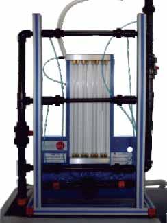
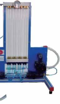
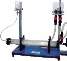
4 1.-Flow measurement. FME00. Hydraulics Bench Unit for the study of fluid behaviour, hydraulic theory and the properties of fluid mechanics. It is formed by a movable hydraulics bench used to hold a wide variety of modules, which allow the student to experiment with the problems presented by fluid mechanics. Autonomous unit (tank and pump included). Innovative water saving system consisting of a high capacity sump tank and spillway that sends the excess of water back to the tank. Easy access drain valve. The volumetric measuring tank is stepped to accommodate for low or high flow rates. A measuring cylinder (1 l.-capacity) is included in the supply for the measurement of very small flow rates. Level tube with scale that shows the water level in the upper tank. Flow adjusted by means of a membrane valve. Flow stilling baffle for reducing the turbulence rate. Specially designed channel, in the upper part, to support the modules on test. The modules are easily mounted on its top without the use of tools. This ensures its simplicity. Manufactured with corrosion resistant materials, ensuring a long and useful life of the unit. Centrifugal pump. Pump breaker starting, safety and contact light. Each module is supplied as a complete piece of equipment with easy and quick coupling to the bench, maximizing the available student s time to perform the demonstrations or the experimental measurements. To be used with the different units of Fluid Mechanics Area: FME type modules, Fluid Friction in Pipes Equipment "AFT", etc., to increase the profitability. AND 1 Base Service Units FME00/B. Basic Hydraulic Feed System Mobile hydraulic bench, made of fibreglass reinforced polyester, and mounted on wheels for its mobility. Centrifugal pump, 0.37 KW, l./min at m., single phase 220V/50Hz or 110V/60Hz. Runner made of stainless steel. Sump tank capacity: 165 l. Small channel: 8 l. Flow measurement: volumetric tank, gauged from 0 to 7 l. for low flow values and from 0 to 40 l. for high flow values. Control valve for regulating the flow. Open channel to place the test module. Measuring cylinder is provided for the measurement of small flow rates. Remote hand-operating dump valve in the base of the volumetric tank. Rapid and easy interchange of the different modules. Dimensions: 1130 x 730 x 1000 mm. approx. Weight: 70 Kg. approx. Electrical supply: single-phase 220V/50 Hz or 110V/60 Hz. Water supply. Drainage. FME00-CR. (on request) The FME00/B is a service unit for different Fluid Mechanics Units as: FME type modules, Fluid Friction in Pipes Unit AFT, etc., increasing the equipment profitability. Centrifugal pump: 0.37 KW, l./min at m., single-phase 220V. / 50Hz. or 110V. / 60Hz. Stainless steel impeller. Tank capacity:140 l. approx. Flowmeter. Membrane type flow adjusting valve. Safety switch ON/OFF. Supports for accommodating the test module. This unit incorporates wheels for its mobility. 1.- Flow measurement. Page 4 Dimensions: 1000 x 600 x 700 mm. approx. Weight: 40 Kg. approx. Water supply. Drainage. Electrical supply: single-phase 220V/50 Hz or 110V/60 Hz.
, is aligned with a device in which the problem")

5 FME01. Impact of a Jet 2 Modules General concepts FME02. Flow over Weirs The module consists of a cylindrical tank with lateral transparent surfaces where a nozzle, connected to the Hydraulics Bench (FME00), is aligned with a device in which the problem surface is fitted. The vertical force made by the water against the surface is measured using calibrated weights that balance this force. Taking as a reference a gauge, which has been previously adjusted to a zero reference, we measure the force thanks to a mark that appears on the surface where the masses were placed. Adjustable supports that let the device balance. Holes made on the tank base in order to drain the water. In this way, splashes are avoided. 1.- Impact against a flat surface. 2.- Impact against a curve surface of 120º. 3.- Impact against a hemispherical surface. 4.- Use of the fast connectors. Jet diameter: 8 mm. Impact surfaces diameter: 40 mm. Impact surfaces: 180 hemispherical surface. 120 curve surface. 90 flat surface. A set of masses of 5, 10, 50 and 100 g. is supplied. Dimensions: 250 x 250 x 500 mm. approx. Weight: 5 Kg. approx. Hydraulics Bench (FME00) or Basic Hydraulic Feed This module has many elements that are used in combination with the Hydraulics Bench (FME00): A special mouthpiece is coupled to the outlet mouthpiece for water in the Hydraulics Bench (FME00). Two soothing screens that, together with the previous element, provide a slow current in the channel. A level meter consisting of a nonius adjusted to a mast, where the heights are pointed out on a caliber coupled to it. A small hook or point is attached to the bottom of the mast to carry out the measures. Two drains (a rectangular neckline and a V-shape) are attached to the final part of the channel of the Hydraulics Bench (FME00). 1.- Study of the flow characteristics through a weir with a rectangular neckline, made on a thin wall. 2.- Study of the flow characteristics through a weir with a V-shape neckline, made on a thin wall. Dimensions of the weirs: 230 x 4 x 160 mm. Neckline angle in the V-shape weir: 90º. Dimension of rectangular notch: 30 x 82 mm. Scale of the level meter: 0 to 160 mm. Dimensions: 400 x 160 x 600 mm. approx. Weight: 7 Kg. approx. Hydraulics Bench (FME00). Page 5
 or the Basic Hydraulic Feed")


6 2 Modules General concepts FME04. Orifice Discharge FME14. Free and Forced Vortex Detail of the 5 type of mouthpieceses The module consists of a transparent cylindrical tank that is fed from the top by the Hydraulics Bench (FME00) or the Basic Hydraulic Feed The water flows through an interchangeable mouthpiece (a set of 5 mouthpieces is supplied, representing orifices of different characteristics) located in the base center. The liquid flowing vein goes directly to the volumetric tank of the Hydraulics Bench or from the Basic Hydraulic Feed System. A Pitot s tube can be placed in any point of the flowing vein to determine its total height of load. A transverse device, joined to the Pitot s tube, allows to determine the diameter of the liquid flowing vein. It s possible to measure the height of the Pitot s tube and the total height through the orifice, in a panel of 2 manometric tubes located beside the tank. 1.- Determination of the discharge coefficient for the mouthpiece of thin wall, Venturi type. 2.- Determination of the velocity coefficient for the mouthpiece of thin wall, Venturi type. 3.- Determination of the contraction coefficient for the mouthpiece of thin wall, Venturi type. 4.- Determination of the discharge coefficient for the mouthpiece of thin wall, diaphragm type. 5.- Determination of the velocity coefficient for the mouthpiece of thin wall, diaphragm type. 6.- Determination of the contraction coefficient for the mouthpiece of thin wall, diaphragm type. 7.- Determination of the discharge coefficient for the mouthpiece of thin wall, colloidal type. 8.- Determination of the velocity coefficient for the mouthpiece of thin wall, colloidal type. 9.- Determination of the contraction coefficient for the mouthpiece of thin wall, colloidal type Determination of the discharge coefficient for the mouthpiece of thick wall, cylindrical type Determination of the velocity coefficient for the mouthpiece of thick wall, cylindrical type Determination of the contraction coefficient for the mouthpiece of thick wall, cylindrical type Determination of the discharge coefficient for the mouthpiece of thick wall, Venturi type Determination of the velocity coefficient for the mouthpiece of thick wall, Ventury type Determination of the contraction coefficient for the mouthpiece of thick wall, Ventury type. Transparent cylindrical tank. Five type of mouthpieces: diaphragm, colloidal, 2 of Venturi and cylindrical. Height of maximum load: 400 mm. Anodized aluminum structure. Dimensions: 450 x 450 x 900 mm. approx. Weight: 15 Kg. approx. Hydraulics Bench (FME00) or Basic Hydraulic Feed The module has a cylindrical and transparent deposit with two inlet pipes diametrically opposed, slightly inclined to produce a whirl. This deposit has an outlet in the center of its base, where 3 mouthpieces with orifices of different diameters can be coupled. These mouthpieces generate the free vortex and a rotor blade creates the forced vortex acting like a flux strangler shaker. The profile of the formed vortex is determined by a vortex height meter, placed in the cylinder s upper part, which measures the diameter of the vortex at different depths. The total pressure can be measured by placing a Pitot s tube in the bridge of measurement. It also has adjustable legs to level the module. 1.- Study of forced vortex without discharge orifice. 2.- Study of forced vortex with discharge orifice. 3.- Study of free vortex. 4.- Analysis of the influence of the jet inlet direction. 5.- Analysis of the influence of the vortex on the discharge velocity. Tank diameter: 300 mm. Tank height: 300 mm Mouthpieces orifice diameters: 8, 16 and 24 mm. Distance between centers: 0, 30, 50, 70, 90 and 110 mm. Pitot tube with measuring points at: 15, 20, 25 and 30 mm radius and a scale. Measurement bridge. Inlet pipes: 9 and 12.5 mm. diameter. Diameter measurement system by Nonius. Blind mouthpiece with X-shaped crosses. Anodized aluminum structure. Dimensions: 600 x 550 x 1400 mm. approx. Weight: 10 Kg. approx. Hydraulics Bench (FME00) or Basic Hydraulic Feed Page 6


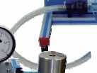
7 2 Modules General concepts FME08. Hydrostatic Pressure FME10. Dead Weight Calibrator The module consists of a quadrant assembled to the arm of a scale that swings around an axis. When the quadrant is immersed in the water tank, the force that acts on the flat rectangular front surface exerts a momentum with respect to the supporting axis. The swinging arm is fitted with a tray and an adjustable counter balance. The tank has adjustable supporting legs for levelling. It has a drainage valve. The level reached by the water inside the tank is indicated by a graduated scale. 1.- Determination of the center of pressures with an angle of 90, partially submerged. 2.- Determination of the resultant force with an angle of 90, partially submerged. 3.- Determination of the center of pressures, angle <> 90 partially submerged. 4.- Determination of the equivalent force with an angle <>90 partially submerged. 5.- Determination of the center of pressures with an angle of 90 totally submerged. 6.- Determination of the resultant force with an angle of 90 totally submerged. 7.- Determination of the center of pressures, angle <>90 totally submerged. 8.- Determination of the resultant force, angle <>90 totally submerged. 9.- Balance of momentum. Tank capacity: 5.5 l. Distance between the suspended masses and the support point: 285 mm. Area of the section: m². Total depth of the submerged quadrant: 160 mm. Height of the support point on the quadrant: 100 mm. A set of masses of different weights is supplied (4 of 100 gr, 1 of 50 gr, 5 of 10 gr, and 1 of 5 gr). Dimensions: 550 x 250 x 350 mm. approx. Weight: 5 Kg. approx. It can work in autonomous way. The module consists of a hollow cylinder in whose interior a precision piston moves. Using a system of calibrated weights, we produce predetermined pressures inside the cylinder. The Bourdon manometer that must be contrasted is connected to the cylinder by means of a flexible pipe. Module levelling through adjustable feet. 1.- Bourdon type manometer calibration. 2.- Hysteresis curve determination. Pressure manometer: Bourdon type bar. Masses (approximated weights): 0.5 kg. 1.0 kg. 2.5 kg. 5 kg. Piston diameter: 18 mm. Piston weight: 0.5 kg. Anodized aluminum structure. Dimensions: 500 x 400 x 500 mm. approx. Weight: 10 Kg. approx. It can work in autonomous way. Page 7
 The module consists of a floating methacrylate prismatic base, with a vertical mast placed on it.")

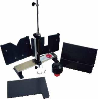
8 FME11. Metacentric Height 2 Modules General concepts FME26. Depression Measurement System (vacuum gauge) The module consists of a floating methacrylate prismatic base, with a vertical mast placed on it. An adjustable mobile mass has been added to alter the position of the center of gravity. An adjustable traverse mass allow for modification of the inclination of the floating base. A plumb line, attached to the upper part of the mast is used to measure the inclination angle of the floating base with a graduated scale. 1.- Study of the stability of a floating body. Angular displacements. 2.- Study of the stability of a floating body. Different positions of the center of gravity. 3.- Determination of the metacentric height. Maximum angle: /- 13. Corresponding lineal dimension: /- 90 mm. Dimension of the float: Length: 353 mm. Width: 204 mm. Total height: 475 mm. Dimensions: 750 x 400 x 750 mm. approx. Weight: 5 Kg. approx. Anodized aluminum structure that supports a vacuum gauge whose reading gives us the measurement. Two quick connections at both sides of the vacuum gauge allow connecting reinforced flexible pipes. 1.- To measure the depression caused for the fluid aspiration by an hydraulic pump. 2.- We can observe the different negative readings due to the different methods of fluid aspiration for its subsequent impulsion. Anodized aluminum structure. Pressure-vacuum gauge adjusted from -1 to 0 bar. Quick connections. Dimensions : 220 x 110 x 420 mm. approx. Weight: 2 Kg. approx. It can work in autonomous way. Scale. Reinforced flexible pipes. Page 8

 or from the Basic Hydraulic Feed System (FME00/B). 1.- Study of the function of a pitot static tube. 2.- To use a pitot static tube. 3.")
9 2 Modules General concepts FME32. Pitot Static Tube Module FME34. Fluid Statics and Manometry With this unit the change in flow speed within a tube can be determined. The Pitot static tube can be moved across the whole crosssection of the tube, and thus to measure the pressure profile. This tube is connected to manometers via hoses. The position of the measuring head relative to the bottom edge of the tube can be measured on a scale. The water supply can come from the Hydraulics Bench (FME00) or from the Basic Hydraulic Feed System (FME00/B). 1.- Study of the function of a pitot static tube. 2.- To use a pitot static tube. 3.- Determination of tube flow speed profiles. 4.- Demonstration that the flow speed is proportional to the pressure difference between the total pressure and the static pressure. 5.- Error determination in flow measurements using the Pitot tube as measurement instrument. 6.- Factor C determination in the Pitot tube. d Pitot static tube: Head diameter: 2.5 mm. Transparent pipe: 32 mm. internal diameter and 430 mm. length approx. Hose connections. Water manometer, 500 mm. length. Anodized aluminum structure and panel of painted steel. Dimensions: 800 x 450 x 700 mm. approx. Weight: 15 Kg. approx. Hydraulics Bench (FME00) or Basic Hydraulic Feed This module has been designed to study static fluids and manometry. It provides the user an introduction to the behaviour of liquids under hydrostatic conditions (fluids at rest) and to the application of those principles in the pressure measurement by using different manometric tubes. It allows the user to demonstrate the properties of Newtonian fluids and to understand a wide range of basic principles before studying fluids in motion. 1.- To study the basic principles of hydrostatics and to demonstrate the behaviour of liquids at rest. 2.- To use manometer tubes to measure differential pressure. 3.- To use a manometer tube to measure head. 4.- To use a U tube manometer to measure pressure differences in a gas (air over liquid). 5.- To use a U-shaped manometer for determining the differential pressure. 6.- To use liquids with different densities to change the U tube manometer sensitivity. 7.- To use an inverted pressurized U tube manometer to measure pressure differences in a liquid. 8.- To use an inclined manometer with different inclinations. 9.- Level measurement using Vernier hook and point gauge To measure the liquid level using a scale Demonstrating that the level of a free surface is not affected by the size or shape of the tube Use of a piezometric tube to measure pressure Observing the effect of a liquid in motion (losses due to friction). The module is mounted on an aluminum structure and painted steel panels and consists of a vertical tank (made of methacrylate, diameter: 100 mm and height: 575 mm) containing water that is connected to different vertical manometer tubes (460 mm length): One U shape vertical tube. Two parallel vertical tubes. One vertical tube with variable section. One vertical tube with a pivot that allows it to incline from 0 to 90º. These tubes can be used individually or in combination for the different demonstrations. Vernier hook and point gauge. Piezometric tube. Manual air pump. Purge valve. Plug to close the tank, so that it is not open to atmospheric pressure. Dimensions: 700 x 350 x 800 mm. approx. Weight: 15 Kg. approx. It can work in autonomous way. Page 9


10 FME35. Fluid Properties 2 Modules General concepts FME36. Rotameter NEW This module has been designed to allows the study of the fundamental properties of fluids and their behaviour in practical applications. We can study capillarity, density and relative density (specific gravity), buoyancy (Archimedes principle), viscosity, atmospheric pressure, etc. 1.- To study the effect of capillary elevation between flat plates. 2.- To study and measure the effect of capillary elevation inside capillary tubes. 3.- To study and verify the Archimedes principle using a bucket and cylinder with a lever balance. 4.- To measure the fluid density and relative density of a liquid using a hydrometer and using a density bottle. 5.- To measure the atmospheric pressure using a barometer. 6.- To measure the fluid viscosity using a falling sphere viscometer. 7.- To measure the fluid temperature using an alcohol thermometer. 8.- Measuring of liquid levels. Anodized aluminum structure and panels of painted steel. 3 Hydrometers of resolution 0.002ºSG: Hydrometer 0.8ºSG - 1ºSG Hydrometer 1ºSG 1.2ºSG Hydrometer 1.2ºSG 1.4ºSG Two hydrometer jars of 450 x 50 mm. Aneroid barometer, range: mbar. Thermometer with a range between -10 and 50ºC. Pycnometer of 50 ml. Parallel plates capillary module. Capillary tubes module with tubes of different size: 5 mm, 4 mm, 3 mm, 2.2 mm, 1.7 mm and 1.2 mm. Two falling sphere viscometer tubes of 300 x 40 mm, with marks at 0, 25, 175, 200 and 220. Set of stainless steel balls of different sizes: mm, mm and mm. Variable scale lever balance to be used with the Archimedes module, up to 310 gr. Archimedes module: displacement vessel, bucket and cylinder. Graduated cylinder made of glass (250 ml.) 2 Beakers made of glass (600 ml.) Digital chronometer. Dimensions: 850 x 500 x 800 mm. approx. Weight: 20 Kg. approx. It can work in autonomous way. The FME36 module is a variable area flowmeter with float. This type of flowmeter can be used for flow rate measurements in almost all media. The operation mode of this flowmeter is based on the fact that if a medium is flowing upwards at a sufficient rate of flow through a vertically mounted tube, the float is raised to the point at which a state of equilibrium sets between the lifting force of the medium and the weight of the float. Since the mean rate of flow is proportional to the quantity flowing through per unit of time, this state of equilibrium corresponds to the measurement of the instantaneous flow rate. An additional advantage of this type of flowmeter is that it does not require minimum straight sections of pipe, therefore it can also be installed directly before or after elbows and valves since the pressure loss is low. 1.- Flow measurement. Anodized aluminum structure and panel of painted steel. Variable area rotameter with float. Measurement range: l./h. Material: transparent PVC. Accuracy class: 4. Quick-plug for an easy connection. Dimensions: 400 x 300 x 900 mm. approx. Weight: 10 Kg. approx. It can work either on its own or with the Hydraulics Bench (FME00). Page 10


11 2 Modules Laws FME03. Bernoulli s Theorem Demonstration FME22. Venturi, Bernoulli and Cavitation Unit Bernoulli s Theorem Demonstration module is mainly composed of a circular section conduit with shape of a truncated cone, transparent and with seven pressure taps to measure, simultaneously, the static pressure of each section. All the pressure taps are connected to a manometer with a water collector (water might be pressurized). The ends of the conduits are removable, enabling to be placed in either convergent or divergent form with respect to the stream direction. There is also a probe (Pitot s tube) moving along the conduit for measuring the height in every section (dynamic pressure). The flow rate and the pressure in the module can be modified by adjusting the control valve located at the end of the module. A flexible hose attached to the outlet pipe is directed to the volumetric measuring tank. For the operation, the module is placed on the Hydraulics Bench (FME00). It has adjustable legs for levelling. The inlet pipe ends in a female coupling which may be directly connected to the bench supply. 1.- Determination of the exact section in Venturi s tube. 2.- Demonstration of Bernoulli s Theorem. Divergentconvergent position. 3.- Determination of Bernoulli s Theorem equation. Convergent-divergent position. 4.- Observation of differences between convergent and divergent position. Manometer range: 0 to 300 mm of water. Number of manometer tubes: 8. Upstream diameter of the throat: 25 mm. Narrowing: Downstream: 21. Upstream: 10. Anodized aluminum structure and panel of painted steel. Dimensions: 800 x 450 x 700 mm. approx. Weight: 15 Kg. approx. Hydraulics Bench (FME00) or Basic Hydraulic Feed This module is designed for demonstrating some practical possibilities with the Venturi s tube. This Venturi is made of transparent methacrylate for a better visualization. It consist of a circular transverse section Venturi tube with 6 taps (Divergent/Convergent). Being transparent, it gives a better visualization of the cavitation phenomenon. It includes a manometer and a vacuum gauge, as well as 5 manometric tubes. 1.- How to fill the manometric tubes. 2.- Flow calculation. 3.- Determination of the exact section in Venturi s tube. Bernoulli s theorem study. 4.- Cavitation study. 5.- Pressure reduction in a tank. 6.- Aspiration pump. 7.- Aspiration pump for mixing two liquids. 8.- Using for air and water mixing. Manometer (Bourdon type), range: bar. Manometer (Bourdon type), range: 0-(-1) bar. 2 Tanks, height: 135 mm and internal diameter: 64 mm. Venturi tube with 6 tappings (Divergent/Convergent). Differential manometers: mm. 5 Manometric tubes. Anodized aluminum structure and panels of painted steel. Dimensions: 750 x 400 x 850 mm. approx. Weight: 10 Kg. approx. Hydraulics Bench (FME00) or Basic Hydraulic Feed Vegetable Colouring (Fluorescein C20H12O5). Page 11

 or the Basic Hydraulic Feed The visualization of the laminar or turbulent regime can be carried out through the flow control valve. 1.")
12 FME06. Osborne-Reynolds Demonstration 2 Modules Laws FME31. Horizontal Osborne-Reynolds Demonstration The module consists of a cylindrical tank endowed with a nozzle, that is fitted to a methacrylate pipe, which allows the fluid visualization. A spillway guarantees the homogeneity of the flow and a needle fitted to the deposit provides the dye. Water is supplied by the Hydraulics Bench (FME00) or the Basic Hydraulic Feed The visualization of the laminar or turbulent regime can be carried out through the flow control valve. 1.- Observation of the laminar, transition and turbulent regime. 2.- Study of the velocity profile, reproducing the Osborne-Reynolds s experiment. 3.- Reynold s number calculation. Tube inner diameter: 10 mm. Tube outer diameter: 13 mm. Visualization pipe length: 700 mm. Capacity of the dye tank: 0.3 l. Tank capacity: 10 l. Flow control valve: diaphragm type. The coloured fluid is regulated with a needle valve. Anodized aluminum structure and panels of painted steel. Dimensions: 450 x 450 x 1250 mm. approx. Weight: 20 Kg. approx. Hydraulics Bench (FME00) or Basic Hydraulic Feed Thermometer. Vegetable Colouring (Fluorescein C20H12O5). The Osborne-Reynolds experiment is used to study the characteristics of a liquid flow through a pipe. It is also used to determine the Reynolds number at each state of the liquid. The FME31 module makes it possible to study the characteristics of the flow of a liquid inside a pipe and the behaviour of such flow. Besides, it is possible to determine the range of the laminar and turbulent flows using the Reynolds number. Thus, difference between laminar, turbulent and transition flows can be demonstrated and the Reynolds number can be calculated for each regime. This module consists on a transparent and horizontal pipe section, which makes it possible to visualize the fluid, a water supply tank, which guarantees the flow homogeneity, and a needle connected to a tank through a hose, from where the dye is supplied. Water flow in the test section can be regulated by means of a valve. Water can be supplied either using the Hydraulics Bench (FME00) or from the Basic Hydraulic Feed 1.- Observation of laminar, transition and turbulent flows. 2.- Association of laminar, transition and turbulent flows with their corresponding Reynolds number. 3.- Observation of the parabolic velocity profile. This module is mounted on an anodized aluminum structure with painted steel panel. Methacrylate test pipe with an airfoil-shaped inlet section: Inner diameter: 16 mm. External diameter: 20 mm. Length: 750 mm. Water supply tank with level fitting and connection for its feeding. It has a section that makes it possible to generate a constant pressure at the tank inlet. Capacity: 2.4 l. Dye or vegetable colouring tank with a valve and an injection needle, tank capacity: 0.4 l. Colouring matter injection is regulated with a needle valve. Control valve to adjust the water flow in the experiments. Dimensions: 1100 x 400 x 700 mm. approx. Weight: 20 Kg. approx. Hydraulics Bench (FME00) or Basic Hydraulic Feed System (FME00/B). Vegetable Colouring (Fluorescein C20H12O5). Thermometer. Page 12


 that moves along the section in order to measure the height of each section (dynamic pressure).")

13 FME24. Unit for the study of Porous Beds in Venturi Tubes (Darcy s Equation) 2 Modules Laws FME33. Pascal s Module Detail of the Venturi s tubes with porous bed Detail of the 3 different vessels The module is formed by a circular section conduit with a truncated cone shape, transparent, and with pressure taps that allow measuring simultaneously the values of static pressure corresponding to any point of different sections. It also has three another conduits, full of sand of different diameters of grain. The conduit ends can be extracted, so they can be placed in a convergent or in a divergent way in regard to the flow direction. There is a probe (Pitot s tube) that moves along the section in order to measure the height of each section (dynamic pressure). The flow velocity in the module can be modified by adjusting the control valve and by using the Hydraulics Bench (FME00) or Basic Hydraulic Feed 1.- Demonstration of Bernoulli s theorem and its limitations in divergent - convergent position. 2.- Demonstration of Bernoulli s theorem and its limitations in convergent-divergent position. 3.- Direct measurement of the static height and of the total distribution of heights in Venturi s tubes. 4.- Determination of the exact section in a Venturi s tube. 5.- Head losses in the porous bed (elements FME24/A, FME24/B and FME24/C). Manometer range: mm. of water. Number of manometric tubes: 8. Strangulation diameter upstream: 25 mm. Narrowing: upstream: 10º. downstream: 21º. Venturi s tube with Pitot tube. Venturi s tube with porous bed of a grain diameter of 1.0 to 1.5 mm (FME24/A). Venturi s tube with porous bed of a grain diameter of 2.5 to 3.5 mm (FME24/B). Venturi s tube with porous bed of a grain diameter of 5.5 to 7.0 mm (FME24/C). Anodized aluminum structure and panels of painted steel. Dimensions: 800 x 450 x 700 mm. approx. Weight: 15 Kg. approx. Hydraulics Bench (FME00) or Basic Hydraulic Feed System (FME00/B). The FME33 module allows to demonstrate Pascal's principle, that is to say, that pressure in an incompressible fluid has no relation with the size of the column section, it only depends on its head (level of the liquid) and on the nature of the liquid. For that purpose, the unit consists of three vessels with the same diameter on their base but different shape, so that they can be compared. It also allows to determine the hydrostatic pressure quantitatively and to study the linear relation between pressure and filling height. This module is made up of a body with a diaphragm or membrane to which any of the three vessels can be attached. The membrane transfers the force to a lever arm that is balanced with masses and a spirit level. A movable pointer adjustable in height located in a vertical rod allows to fix the height of the water in the vessels to the same level, so that the force or pressure is common for the three vessels regardless their shape. 1.- Demonstration of Pascal's principle by comparing three vessels of different shape. 2.- Determining the hydrostatic pressure. 3.- Determining the linear relation between pressure and filling head of the vessel. Anodized aluminum profile frame and painted steel panel that guarantees good stability and resistance to the environment. Three vessels of 230 mm high: Straight shaped vessel with internal diameter of 26 mm. Conical vessel with internal diameter from 26 mm. to 80 mm. Inverted conical vessel with internal diameter from 26 mm. to 10 mm. Support for the vessel and membrane. Lever arm and spirit level to measure the weight at the base of the vessel. Fastening nut for levelling. Masses set. Vertical rod with portable indicator to fix the fluid level in the vessels. Dimensions: 550 x 350 x 500 mm. approx. Weight: 7 Kg. approx. It can work in autonomous way. Page 13

 or the Basic Hydraulic Feed System (FME00/B), by means of a flexible pipe, passes through a damping tank that")


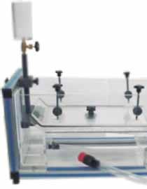
14 2 Modules Demonstration FME09. Flow Visualization in Channels FME20. Laminar Flow Demonstration Detail of the hydrodynamic models Detail of the hydrodynamic models The module consists of a transparent methacrylate channel with an overflow pipe on top and an adjustable plate in the discharge end. This plate allows for regulating the flow level. The water is supplied to the channel by the pulse mouth of the Hydraulics Bench (FME00) or the Basic Hydraulic Feed System (FME00/B), by means of a flexible pipe, passes through a damping tank that eliminates the turbulences. It has a colouring injection system consisting of a tank, a flow control valve and some needles that allow a better visualization of the flow around the different hydrodynamic models, which have to be placed in the middle of the channel. Module levelling through adjustable feet. Several hydrodynamic models are given to study the flow around them. 1.- Leakage of liquids by thin-wall weirs. 2.- Liquid leakage by thick-wall weirs. 3.- Models with wing profile submerged in a fluid current. 4.- Circular models submerged in a fluid current. 5.- Demonstration of the phenomenon associated to the flow in open channels. 6.- Visualization of the flow lines around different submerged hydrodynamic models. Capacity of the dye tank: 0.3 l. Width/length of the channel approx.: 15/630 mm. Depth of channel approx.: 150 mm. Damping tank that eliminates the turbulences. Hydrodynamic models: Two lengthened. Two circular of 25 and 50 mm. diameter. Rectangle with rounded edges. Wedge. Anodized aluminum structure. Dimensions: 900 x 450 x 500 mm. approx. Weight: 7 Kg. approx. Hydraulics Bench (FME00) or Basic Hydraulic Feed Vegetable Colouring (Fluorescein C20H12O5). This module allows a complete study of the bidimensional problems associated with laminar flow. Thanks to an efficient system of dye injection we can observe the different models of flow. It consists on an enlargement of the device of Hele-Shaw. Water is supplied to the accessory from the driving mouth of the Hydraulics Bench (FME00) or from the Basic Hydraulic Feed System (FME00/B), by a flexible pipe. Then, water passes through a damping deposit that eliminates the turbulence. It has a dye injection system, which consists of a deposit, a flow control valve and some needles that allow for a better visualization of the flow around the different hydrodynamic models, placed in the central part of the channel. The module can be levelled with the adjustable legs. 1.- Ideal flow around a submerged cylinder. 2.- Ideal flow around a submerged profile. 3.- Ideal flow around a body in peak. 4.- Ideal flow in a convergent channel. 5.- Ideal flow in a divergent channel. 6.- Ideal flow in an elbow of 90º. 7.- Ideal flow in a sudden contraction. 8.- Ideal flow in a sudden broadening. 9.- Substitution of a line of current for a solid edge. Capacity of dye tank: 0.3 l. Width/length of the table: 400/210 mm. Depth of the table: adjustable depending on the models. Hydrodynamic models: Two circular ones of 25 and 50 mm. diameter. Two rectangular ones of 25 x 25 and 50 x 50 mm. Wedge. Anodized aluminum structure. Dimensions: 870 x 450 x 400 mm. approx. Weight: 10 Kg. approx. Hydraulics Bench (FME00) or Basic Hydraulic Feed Vegetable Colouring (Fluorescein C20H12O5). Page 14


15 2 Modules Demonstration FME30. Vortex Flow Meter FME15. Water Hammer The design of the FME30 module makes it possible to study different methods of volumetric and mass flow measurement, as well as to compare continuous and intermittent methods. This module includes two continuous and two intermittent methods to carry out the experiments. The continuous methods include a vortex flowmeter and a variable-area flowmeter (or rotameter). A series of oscillating vortices, where the oscillating frequency is proportional to the flow rate, are generated in the vortex flowmeter. Dye or colouring is used to visualize such vortices. Intermittent methods include the measurement of volumetric and mass flows. A precision scale is used to measure the mass flow and compare the measurements. The water supply may be provided either from the Hydraulics Bench (FME00) or the Basic Hydraulic Feed 1.- Study and experiments with a vortex flow meter. 2.- Study and experiments with a variable area flow meter. 3.- Measurement of volumetric volume flow rate. 4.- Measurement of gravimetric volume flow rate. 5.- Comparison of methods on several volumetric and mass flow measurements. 6.- Flow meters calibration. 7.- Comparison among different flowmeters. Structure of anodized aluminum and panels of painted steel. PVC pipe to connect to a water supply of the Hydraulics Bench (FME00) or the Basic Hydraulic Feed Needle valve to control the flow at the pipe inlet. Vortex flow meter with flow oscillation made visible by dye injection. Variable-area flow meter (rotameter), range: l./min. Two regulating ball valves to control the flow in the vortex and variable-area flow meters. Water tank at a constant height and connection for its drainage, capacity: 2.4 l. Dye or colouring tank with control valve, capacity: 0.4 l. A control ball valve to regulate the flow at the pipe's outlet. Quick connection system. A digital precision balance, range: gr., graduated at 1 gr. Graduated glass vessel with a capacity of 2 l. Dimensions: 900 x 570 x 900 mm. approx. Weight: 30 Kg. approx. Hydraulics Bench (FME00) or Basic Hydraulic Feed System (FME00/B). Vegetable colouring (Fluorescein C20H12O5). The module is designed to demonstrate the effects of instantaneous or gradual velocity variation in a fluid. As a consequence of a quick change in the velocity of a fluid, the Water Hammer phenomenon can be studied. 1.- Subduing of the water hammer effects. 2.- Study of the subduing depending on the diameter of the chimney. 3.- Calculations of the energy losses in pipes. Constant level deposit, in methacrylate. Unload deposit, in methacrylate. Pipe circuits in PVC. Valves to select the circuit. 2 adjustable equilibrium chimneys and subjection clips. Connections system to the Hydraulics Bench (FME00) or Basic Hydraulic Feed System (FME00/B) with fast plugs. Anodized aluminum structure. Dimensions: 1215 x 270 x 1430 mm. approx. Weight: 15 Kg. approx. Hydraulics Bench (FME00) or Basic Hydraulic Feed Page 15


16 FME19. Cavitation Phenomenon Demonstration 2 Modules Demonstration FME18. Flow Meter Demonstration The module consists of a rectangular transversal section Venturi-pipe, with transparent wall for a better observation of the Cavitation Phenomenon. It includes a manometer and a vacuum meter that are respectively connected to the inlet section and to the reduction throat section. The existing pressure in the Venturi sections is transmitted by thin capillary tubes placed at the back of the frame. 1.- Study of cavitation. 2.- Visualization of the cavitation phenomenon with forced conduction. Manometer range: 0 to 2.5 bar. Vacuum gauge range: from-1 to 0 bar. Throat section: 36 mm². Normal section: 150 mm². Anodized aluminum structure and panel of painted steel. Dimensions: 750 x 400 x 650 mm. approx. Weight: 5 Kg. approx. Hydraulics Bench (FM00) or Basic Hydraulic Feed System (FME00/B). The module consists of a Venturi meter, a flowmeter and an orifice plate, installed in a series configuration to permit a direct comparison. Several pressure taps are connected to a panel of eight tubes. The flow control valve allows the variation of the flow rate through the circuit, and its adjustment, along with the bench control valve, allows for varying the system static pressure. The pressure taps of the circuit are connected to an eight-bank manometer, which incorporates an air inlet valve at the top manifold which facilitates the connection to the hand pump. This enables to adjust the levels in the manometer bank to a convenient level to suit the system static pressure. 1.- Filling of the manometric tubes. 2.- Determination of the error in flow measurements using the Venturi. 3.- Determination of the C d factor in the Venturi. 4.- Determination of the strangulation in the Venturi. 5.- Determination of the error in flow measurements using the orifice plate. 6.- Determination of the C d factor in the orifice plate. 7.- Determination of the effective area in an orifice plate. 8.- Comparison of the energy loss in the three different elements. 9.- Comparison among the Venturi, the orifice plate and the flowmeter. Manometer range: 0 to 500 mm. of water column. Number of manometric tubes: 8. Orifice plate diameter: 25 mm. Flowmeter: 2 to 30 l./min. Venturi dimensions: Throat diameter: 20 mm. Upstream pipe diameter: 32 mm. Downstream taper: 21. Upstream taper: 14. Orifice Plate dimensions: Upstream pipe diameter: 35 mm. Downstream orifice diameter: 19 mm. Anodized aluminum structure and panel of painted steel. Dimensions: 750 x 450 x 950 mm. approx. Weight:10 Kg. approx. Hydraulics Bench (FME00) or Basic Hydraulic Feed System (FME00/B). Page 16
 NEW FME25TP FME25SDL FME25RMC FME25CV FME25PRS FME25VD FME25VG FME25PV This module has been designed for studying the behaviour of water flowing through a one-meter channel.")


 that is introduced in the channel to measure pressures and obtain the speed and flow rates at different points of the channel.")
17 FME25. Flow Channel, 1m. length 2 Modules Demonstration Accessories for the Flow Channel, 1m. length (FME25) NEW FME25TP FME25SDL FME25RMC FME25CV FME25PRS FME25VD FME25VG FME25PV This module has been designed for studying the behaviour of water flowing through a one-meter channel. It basically consists of a channel of rectangular cross section with transparent walls, through which water flows. It has a mechanism that allows to vary the shape of the channel and it can directly be placed on the Hydraulics Bench. Water is taken from the tank of the Hydraulics Bench (FME00) or the Hydraulic Feed System (FME00/B) by means of a pump and, through the pipe, it is driven to the tank, where there is a settling of the flow. After this, the water circulates through the channel and returns to the storage tank. Therefore, the closed circuit is completed. There is a mechanism that allows to adjust the slope of the channel. 1.- Study of the fundamental aspects of fluid flow. Practical possibilities depending on the accessories used: 2.- Measurement of water level and velocity along the channel. 3.- Measurement of flow rate using a Pitot tube. 4.- Determination of the static and total pressure. 5.- Use of hydraulic structures to control level. 6.- Study of the effects of gradual and sudden changes in cross section (energy losses). 7.- Use of a contraction to measure flow. 8.- Use of hydraulic structures to measure flow in an open channel. 9.- Study of flow patterns associated with flow around hydraulic structures Comparison between the theoretical and experimental flow. Channel of rectangular section with transparent walls in methacrylate, length: 1 m. Rigid and flexible pipes. Regulating valves. Storage tank. Tank with soothing of flow. Anodized aluminum structure. Wide range of available accessories. Dimensions: 1500 x 500 x 500 mm. approx. Weight: 40 Kg. approx. Hydraulics Bench (FME00) or Basic Hydraulic Feed System (FME00/B). FME25TP. Pitot tube. Pitot tube with a panel (with two manometric tubes) that is introduced in the channel to measure pressures and obtain the speed and flow rates at different points of the channel. The FME25TP accessory consists of a Pitot tube mounted on a movable XYZ stand, which can move all the length and breadth of the flow channel, and a panel with two manometric tubes to measure static and total pressure. The difference between both pressures allows us to calculate the speed of the fluid and, knowing the section, the flow can be calculated at any point. Practical possibilities: 1.- Measurement of the flow rate with a Pitot tube. 2.- Determination of the static and total pressure. 3.- Filling of manometric tubes. FME25CV. Vertical flat gate. The FME25CV accessory is a vertical flat gate made of PVC that is located at the outlet of the channel to avoid the flow of fluid. FME25SDL. Syphon spillway. One way to regulate the flow in a channel is by using a syphon. When the level exceeds a specific height, water flows through the syphon and the level is regulated upstream of the syphon. The FME25SDL accessory can be fixed to any part of the channel. Practical possibilities: 1.- Understanding the operation of a syphon with free discharge. 2.- Calculation of the maximum flow admitted by the syphon. 3.- Level control through a syphon with free discharge. FME25SDS. Self-regulating syphon. One way to regulate the flow in a channel is by using a syphon. When the level exceeds a specific height, water flows through the syphon and the level is regulated upstream of the syphon. The FME25SDS accessory can be fixed to any part of the channel. Practical possibilities: 1.- Understanding the operation of a syphon with submerged discharge. 2.- Calculation of the maximum flow admitted by the syphon. 3.- Level control through a syphon with submerged discharge. continue... Page 17

18 Accessories for the Flow Channel, 1m. length (FME25) NEW 2 Modules Demonstration FME17. Orifice and Free Jet Flow FME25RM. Scale to measure the water level (limnimeter). The limnimeter is used to measure the water level in the flow channel. The instrument consists of several feeler tips that can move along a graduated scale from 0 to 500 mm. to obtain the level. The scale is divided into tenth parts of a millimeter (adjustable Vernier scale). Main metallic elements are made of stainless steel and this device can move along the whole channel. Practical possibilities: 1.- Use of a limnimeter. 2.- Measuring the water level in the flow channel. FME25PR. Adjustable undershot weir. One way to regulate the flow in a channel is by using control gates. When the gate is totally closed, no water flows, and when the gate is open, water starts to flow through the channel. The FME25PR accessory consists of a PVC gate mounted on a frame that can be displaced along the channel. This system allows the gate to be fixed to the desired height and to measure that height. It has flexible lateral reinforcements that guarantee watertightness. Practical possibilities: 1.- Flow control with gates. 2.- Observation of discharge processes when using a weir. 3.- Observation of alternating changes during the discharge. FME25VD. Sharp crested discharge weirs (two different models). Sharp crested weirs are hydraulic weirs, generally used to measure flow rates. Their name is due to the fact that the discharge is done through a plate whose profile, regardless of its shape, ends in a sharp edge. The FME25VD accessory includes 2 weirs (a V shaped and a U shaped one) made of PVC lodged in slots, reinforced with flexible rubber, designed for that purpose at the outlet of the channel, guaranteeing watertightness. Practical possibilities: 1.- Comparison between the main types of weirs. 2.- Measurement of the flow rate with a triangular sharp-crested weir (V shaped). 3.-Measurement of the flow rate with a rectangular sharpcrested weir (U shaped). 4.- Comparison between the theoretical and experimental flows. FME25VG. Broad-crested weirs (two different models). Broad crested weirs have a lower discharge capacity for the same volume of water than sharp crested weirs. They are most frequently used as level control structures, although they can also be calibrated and used as flow measurement structures. The FME25VG accessory includes two broad crested weirs, made of PVC, which can be fixed to any part of the bottom of the channel. The edge of one of the weirs is rounded and the edge of the other one is straight. Both weirs have flexible lateral reinforcements that guarantee watertightness. Practical possibilities: 1.- Measurement of the flow rate with a broad crested weir. 2.- Comparison between the theoretical and experimental flows. FME25PV. Ogee-crested weir. The Ogee weir is a fixed weir, that is to say, it does not allow regulation of the water surface profile. They are used to divert flow rates since, if it is compared to other types of weirs, the special shape of their crest enables the maximum discharge for the same water level. It is made of PVC, can be fixed to any part of the bottom of the channel and has flexible lateral reinforcements that guarantee watertightness. Practical possibilities: 1.- Measurement of the flow rate with an Ogee-crested weir. 2.- Comparison between the theoretical and experimental flows. The module consists of a cylindrical methacrylate tank that enables to maintain a constant level and that is fed by the Hydraulics Bench (FME00) or by the Basic Hydraulic Feed Two nozzles with orifices of different diameters are provided. They are placed in the base of the tank, and can easily be interchanged. The trajectory of the jet can be drawn by following the position of some vertical needles placed in the annexed panel. These are adjusted by means of some command screws. This panel includes a silk-screen scale that enables to measure the profile of the jet. Adjustable feet permit levelling. 1.- Determination of the orifice velocity coefficient. 2.- Obtaining of the orifice discharge coefficient in permanent regime. 3.- Obtaining of the orifice discharge coefficient in variable regime. 4.- Obtaining of the tank discharge time. Orifices with diameters of 3.5 and 6 mm. Jet trajectory Probes: 8. Maximum height: 500 mm. Anodized aluminum structure. Dimensions: 600 x 550 x 1400 mm. approx. Weight: 10 Kg. approx. Hydraulics Bench (FME00) or Basic Hydraulic Feed Page 18
 or the Basic Hydraulic Feed This module consists of a hydraulic circuit with a set of elements that disrupt the normal")
19 FME05. Energy Losses in Bends 2 Modules Pipes FME07. Energy Losses in Pipes This module can work with the Hydraulics Bench (FME00) or the Basic Hydraulic Feed This module consists of a hydraulic circuit with a set of elements that disrupt the normal flow of the fluid that circulates by the pipe, due to sudden section and direction variations, as well as friction. These elements are: Two 90º elbows, a short one and a middle one. A 90º curve or long elbow. A broadening. A sudden narrowing section. A sudden direction change, miter type. The module has two manometers, Bourdon type: bar and twelve manometric pipes of pressurized water. The system pressurization is carried out with a manual air pump. The hydraulic circuit has pressure tappings along the whole system, which enable to measure the local load losses in the system. This module has two membrane valves, a valve which enables the regulation of the outlet flow, and a valve placed in series with the rest of accessories of the hydraulic circuit. 1.- Filling of the manometric tubes. 2.- Measurement of the flow. 3.- Measurement of load losses for a short elbow of 90º. 4.- Measurement of load losses for a medium elbow of 90º. 5.- Measurement of load losses for a curve of 90º. 6.- Measurement of load losses for a broadening of 25/ Measurement of load losses for a narrowing 40/ Measurement of load losses for a miter type abrupt direction change. 9.- Measurement of load losses for a membrane valve. Range of the two Bourdon type manometers: 0 to 2.5 bar. Differential manometers range: 0 to 500 mm. Number of manometric tubes: 12. PVC Rigid pipes: Internal diameter: 25 mm. External diameter: 32 mm. Flexible pipes: Pressure taking-differential manometer. External diameter: 10 mm. Pressurizing equipment. External diameter: 6 mm. Drain. External diameter: 25 mm. Fittings: Miter (90º angle). 90º curve. 90º medium elbow. 90º short elbow. 90º long elbow. Broadening of 25/40. Narrowing of 40/25. Valves: Membrane valves. Diameter: 25 mm. Antireturn: 6 mm. Anodized aluminum structure and panel of painted steel. Dimensions: 750 x 550 x 950 mm. approx. Weight: 10 Kg. approx. Hydraulics Bench (FME00) or Basic Hydraulic Feed The module consists of the following elements, used in combination with the Hydraulics Bench (FME00) or the Basic Hydraulic Feed System (FME00/B): Pipe with quick connector to be coupled to the water outlet s mouthpiece at the Hydraulics Bench (FME00) or the Basic Hydraulic Feed 6 mm external/4 mm inner diameter metallic test pipe. One water column differential manometer. Constant height tank. Two Bourdon type manometers. 1.- Energy loss in pipes for a turbulent regime. 2.- Determination of the energy loss in a turbulent regime. 3.- Determination of the number of Reynolds for a turbulent regime. 4.- Energy loss in pipes for a laminar regimen. 5.- Determination of the energy loss factor f for a pipe in laminar regime. 6.- Determination of Reynolds number for the laminar regime. 7.- Determination of the kinematic viscosity of water. Test pipe of 4 mm. of inner diameter, 6 mm. of external diameter and 500 mm. of length. 1 differential manometer of water column. Manometer scale: 0 to 500 mm (water). 2 Bourdon type manometers, range: 0 to 2 bar. Constant height tank. Anodized aluminum structure and panels of painted steel. Dimensions: 330 x 330 x 900 mm. approx. Weight: 30 Kg. approx. Hydraulics Bench (FME00) or Basic Hydraulic Feed Thermometer. Page 19


20 FME23. Basic Pipe Network Unit 2 Modules Pipes AFT/P. Fluid Friction in Pipes Unit This pipe network module is designed for the study of pressures and flows created by interconnected pipes, i.e. in a network. The objective of this module is to simulate the problems that could originate in pipe networks, with pipes of different lengths and diameters, as often happens in cities. With this study, the distribution and arrangement of the networks will be understood, in order to obtain the necessary flows and pressures in them. The module is formed by a pipe network, valves, their connection systems, water manometers and anodized aluminum structure where the pipes network is located and the subjection panel of the manometers. 1.- Load loss in a PVC pipe. 2.- Load loss in a methacrylate pipe. 3.- Study of the load loss in pipes made of the same material. 4.- Study of the load loss depending on the material. 5.- Friction coefficient in a PVC pipe. 6.- Friction coefficient in a methacrylate pipe. 7.- Study of the friction coefficient depending on the material. 8.- Study of the friction coefficient depending on the diameter. 9.- Configuration of network in parallel for pipes of the same material but different diameter Configuration of network in parallel for pipes of the same diameter but different material. Anodized aluminum structure where the pipe network is located and the subjection panel of the manometers. Test pipes: Three PVC pipes, with different diameters. One methacrylate pipe. 8 Pressure intakes, connected to a manometric tubes panel of pressurized water. Pressurization system. Manometric tubes panel: Number of manometric tubes: 8. Range: 0 to 470 mm of water. Inlet pipe. Outlet pipe. Regulation valves for controlling the flow through the network. Adjustable legs for leveling the unit. Dimensions: 600 x 350 x 800 mm. approx. Weight: 30 Kg. approx. Hydraulics Bench (FME00) or Basic Hydraulic Feed System (FME00/B). The Fluid Friction in Pipes Unit (AFT/P) is designed to determine the friction coefficient in pipes, to study the pressure losses in different types of valves and different fittings and to compare different methods to measure the flow. This unit contains five straight pipe sections made of different materials and with different diameters and roughness. Additionally, a wide range of accessories are included for the study of losses in straight pipes, several types of valves, pipe fitting, etc. The different pipe sections, valves and pipe fittings include several pressure measurement points with quick action connections. The unit includes two water manometric tubes, two Bourdon manometers and a flowmeter. 1.- Determination of pressure loss due to friction in pipes made of different materials and with different diameters and roughness. 2.- Study of the influence of the diameter in the pressure loss due to friction in rough and smooth pipes. 3.- Study of the influence of the roughness on the pressure loss. 4.- Determination of the friction coefficient in pipes with different diameters and roughness. 5.- Study of the influence of the diameter on the friction coefficient in rough and smooth pipes. 6.- Comparison of the friction coefficient in smooth and rough pipes. 7.- Determination and comparison of pressure loss in different types of valves (angle-seat valve, gate valve, diaphragm valve, ball valve). 8.- Determination and comparison of pressure loss in different fittings (in-line strainer, elbows, narrowing, gradual widening, etc.). 9.- Measurement of the flow with the Venturi tube and the Pitot tube Determination and comparison of the discharge coefficient determined in the Venturi tube and the Pitot tube. 5 Pipes of different internal diameter, roughness and materials. 4 Different types of valves (angle-seat, gate, diaphragm and ball). 10 Different types of couplings (in-line strainer, elbows, sudden widening, sudden contraction, etc.). 3 Special couplings: Pitot tube, Venturi tube and diaphragm with measuring plate. 34 Pressure tappings with quick action connections. Two water manometers, range: mm. Two Bourdon manometers, range: bar One flowmeter, range: l./h. Dimensions: 2300 x 850 x 1100 mm. approx. Weight: 100 Kg. approx. It can work in autonomous way, or with Hydraulics Bench (FM00) or Basic Hydraulic Feed For information in detail see AFT/P catalogue. Click on the following link: /products/catalogues/en/units/fluidmechanicsaerodynamics/ fluidmechanicsgeneral/aft-p.pdf Page 20
 or the Basic Hydraulic Feed This module has three Bourdon-type")

21 2 Modules Hydraulic Machines FME12. Series/Parallel Pumps FME13. Centrifugal Pumps Characteristics The module consists of a pump of similar characteristics to the one in the Hydraulics Bench (FME00) or the Basic Hydraulic Feed This module has three Bourdon-type manometers: two of manometric pressure and one of absolute pressure. The absolute pressure manometer has been placed at the pump input; the other two at the discharge and at the discharge accessory supplied with the module. The accessory has a flow-regulating valve. Moreover, for the parallel connection, a Y-shape accessory is supplied with two ball-valves. This accessory is connected to both pumps and to the discharge device. The module includes an easy connection system for the installation of pumps in series and in parallel. 1.- Water flow calculation. 2.- H (Q) curve obtaining of a centrifugal pump. 3.- Series coupling of two pumps with the same characteristics. 4.- Parallel coupling of two pumps with the same characteristics. Centrifugal pump: 0.37 KW, l./min. at m., single-phase, 220V/50 Hz or 110V/60 Hz. Absolute pressure manometer placed at the pump input, range - 1 to 3 bar. 2 Manometers (manometric pressure), one of them placed in the discharge and the another one in the discharge accessory, range: 0-4 bar. Membrane valve for flow regulating. Two way valve: 2 positions: open or close. Accessories: Two flexible pipes with quick connections. Reinforced pipe with quick connections. Discharge accessory. Anodized aluminum structure and panels of painted steel. Dimensions of the FME12 module: 500 x 400 x 400 mm. approx. Dimension of the discharge accessory: 500 x 400 x 250 mm. approx. Weight: 20 Kg. approx. Hydraulics Bench (FME00) or Basic Hydraulic Feed Electrical supply: single-phase 220V/50 Hz or 110V/ 60Hz. The module has a centrifugal pump with similar characteristics to the one in the Hydraulics Bench (FME00) and the Basic Hydraulic Feed It is armed with two Bourdon-type pressure manometers placed at the pump s inlet and outlet. There is another one in the discharge accessory supplied with the module. The pump is driven by a three-phase asynchronous motor whose speed can be varied by a speed variator. The module has visualization display that allows to know the r.p.m. and the power consumed. It is included a discharge accessory, with manometer, flow control valve and diffuser. The variator s control panel allows to vary the pump speed and the start. 1.- Obtaining of the curves H (Q), N (Q), Eff% (Q) of a centrifugal pump. 2.- Making of the map of a centrifugal pump. 3.- Representation of the adimensional curves H*, N* and rpm*. 4.- Series coupling of two pumps of similar characteristics. 5.- Series coupling of two pumps of different characteristics. 6.- Parallel coupling of two pumps of similar characteristics. 7.- Parallel coupling of two pumps of different characteristics. Centrifugal pump: 0.37 KW, l./min. at m. with speed variator. Bourdon type manometers. Control panel for the variator, allowing to modify the speed, with visualization display that allows to know the r.p.m. and the power consumed, and with on/off switch. Discharge accessory, with manometer, flow control valve and diffuser. Vacuum meter. Anodized aluminum structure and panels of painted steel. Dimensions: 450 x 500 x 1250 mm. approx. Weight: 40 Kg. approx. Hydraulics Bench (FME00) or Basic Hydraulic Feed System (FME00/B). Electrical supply: single-phase, 220V/50 Hz or 110V/60 Hz. Page 21

, P (Q, n) and m (Q, n); (20º nozzle). 4.")
22 2 Modules Hydraulic Machines FME27. Axial Flow Turbine FME16. Pelton Turbine This module consists of an Axial Turbine, in miniature, with 8 inclined nozzles at 20º and 30º degrees with respect to the perpendicular direction at the rotating axis. The pallets of the turbine runner are clearly visible through the transparent tank. A band brake connected to one load cell varying the load given to the turbine by means of a connection device. 1.- Flow calculation. 2.- Determination of the discharge coefficient of the nozzle. 3.- Determination of the curve N (Q,n), P (Q, n) and m (Q, n); (20º nozzle). 4.- Determination of the curve N (Q,n), P (Q, n) and m (Q, n); (30º nozzle). 5.- Adimensional analysis. Nozzle: Inlet diameter of the throat: 2.5 mm. Outlet diameter of the throat: 2.5 mm. Discharge angle: 20º and 30º. Turbine rotor: External diameter: 53 mm. Internal diameter: 45 mm. Number of blades: 40. Inlet angle of the blades: 40º. Outlet angle of the blades: 40º. Used material: Brass. Brake: Pulley diameter: 60 mm. Real diameter: 50 mm. Bourdon type manometer. 8 ball valves. Anodized aluminum structure. Tachometer. Dimensions: 550 x 300 x 600 mm. approx. Weight: 20 Kg. approx. Hydraulics Bench (FME00) or Basic Hydraulic Feed This module comprises a miniature Pelton s Turbine with a retractable needle valve that allows to adjust the flow. The Pelton s Turbine runner is clearly visible through the transparent cover of the turbine. A manometer placed at the inlet of the turbine enables to measure the inlet pressure at that point (water discharge pressure). A band brake, connected to two dynamometers allows varying the load supplied to the turbine by means of a connection device. The turbine axis velocity is determined by an optic tachometer. 1.- Determination of the operative characteristics of the Pelton Turbine. 2.- Determination of the operation mechanical curves. 3.- Determination of the operation hydraulic curves. 4.- Adimensionalization. Speed range: r.p.m. Power: 10 W. Manometer range: bar. Number of buckets: 16. Drum radius: 30 mm. Dynamometers range: 0-20 N. Anodized aluminum structure. Tachometer. Dimensions: 750 x 400 x 750 mm. approx. Weight: 15 Kg. approx. Hydraulics Bench (FME00) or Basic Hydraulic Feed Page 22
 or Basic Hydraulic Feed It includes a distributor with adjustable guide vanes that allow for control of the")


23 FME28. Francis Turbine 2 Modules Hydraulic Machines FME29. Kaplan Turbine Detail of the turbine Detail of the turbine This unit consists on a miniature Francis turbine. The water inlet flow is controlled by a valve situated in the Hydraulics Bench (FME00) or Basic Hydraulic Feed It includes a distributor with adjustable guide vanes that allow for control of the water angle of incidence in the turbine. To adjust the turbine distributor, the unit has a lever on the front of the same. It also has a braking system, connected to two dynamometers, that allows to vary the load supplied to the turbine. It is provided with a draft tube that consists of a conduction that joins the turbine with the outlet channel; its objective is to recover the maximum amount of water kinetic energy when it gets out of the turbine. The inlet pressure of the turbine is measured with a manometer situated at the turbine inlet. The feed or spiral chamber is provided with a damping cover and two tubes to avoid water overflow. Its name indicates that it is spiral-shaped and for this reason it is known as snail chamber. Thanks to its design, the water flows at a constant velocity without forming swirls. This way, there are no load losses. The turbine's axis velocity is determined by a tachometer. 1.- To determine the operating characteristics of a Francis turbine at different velocities. 2.- Determination of the typical turbine curves (operating mechanical curves and operating hydraulic curves). 3.- Turbine power output versus speed and flow rate at various heads. 4.- Effect of guide vane setting on turbine performance. 5.- Adimensionalization. Functional model of Francis turbine. Velocity range: r.p.m. Power: 5 W. Diameter of the turbine: 52 mm. Number of blades on the turbine: 15. Number of adjustable guide vanes of the distributor: 10. Manometer range: mbar. Braking system connected to 2 dynamometers: dynamometers range: 0-10 N. Feed chamber. Draft tube. Anodized aluminum structure. Tachometer. Dimensions: 500 x 350 x 600 mm. approx. Weight: 20 Kg. approx. Hydraulics Bench (FME00) or Basic Hydraulic Feed System (FME00/B). This unit consists on a miniature Kaplan turbine. The water inlet flow is controlled by a valve situated in the Hydraulic Bench (FME00) or Basic Hydraulic Feed It includes a distributor with adjustable guide vanes that allow for control of the water flow in the turbine. It has a braking system, connected to two dynamometers, that allows to vary the load supplied to the turbine. The feed or spiral chamber is provided with a damping cover and two tubes to avoid water overflow; its name indicates that it is spiral-shaped and for this reason it is known as snail chamber. Thanks to its design, the water flows at a constant velocity without forming swirls; this way, there are no load losses. It is also provided with a draft tube that consists of a connection that joins the turbine with the outlet channel; its objective is to recover the maximum amount of water kinetic energy when it gets out of the turbine. The inlet pressure of the turbine is measured with a U-manometer situated at the turbine inlet. The turbine's axis velocity is determined by a tachometer. 1.- Determination of the operative characteristics of Kaplan Turbine at different velocities. 2.- Flow calculation. 3.- Determination of the operation mechanical curves. 4.- Determination of the operation hydraulic curves. 5.- Adimensional analysis. Functional model of Kaplan Turbine. Velocity range: r.p.m. Power: 10 W. Number of blades of the turbine: 4. Turbine diameter: 52 mm. Number of adjustable guide vanes of the distributor: 8. Manometer range: mm. of water. Braking system connected to 2 dynamometers: dynamometers range: 0-10 N. Feed chamber. Draft tube. Anodized aluminum structure. Tachometer. Dimensions: 500 x 350 x 600 mm. approx. Weight: 20 Kg. approx. Hydraulics Bench (FME00) or Basic Hydraulic Feed System (FME00/B). Page 23

24 2 Modules Hydraulic Machines FME21. Radial Flow Turbine This module consist of a miniature Radial Turbine with two nozzles at 180º degrees with respect to the perpendicular direction at the rotating axis. A Bourdon type manometer is placed at the inlet nozzle. A band brake connected to a dynamometer allows to control the load given to the turbine. A tachometer determines the velocity measurement. 1.- Flow calculation. 2.- Obtaining of the M (n, H a), N(n, H a), (n, H a) curves. 3.- Obtaining of the M (n, Q), Nm (n, Q), (n, Q) curves. 4.- Adimensionalization. Nozzles: Inlet diameter: 21 mm. Outlet diameter: 2.0 mm. Discharge angle: 180º. Turbine rotor: External diameter: 69 mm. Internal diameter: 40 mm. Number of nozzles: 2. Inlet angle to the nozzle: 180º. Outlet angle to the nozzle: 180.º Used material: aluminum. Brake: Pulley diameter:60 mm. Effective diameter: 50 mm. Anodized aluminum structure. Tachometer. Dimensions: 800 x 500 x 600 mm. approx. Weight: 50 Kg. approx. Hydraulics Bench (FME00) or Basic Hydraulic Feed Page 24
, this complete software package consists on")
: The Instructor can: Organize Students by Classes and Groups. Create easily new entries or delete them.")


25 3 CAI. Computer Aided Instruction Software System Module Instructor Software Student/Module Software With no physical connection between module and computer (PC), this complete software package consists on an Instructor Software (INS/SOF) totally integrated with the Student/Module Software (FME../SOF). Both are interconnected so that the teacher knows at any moment what is the theoretical and practical knowledge of the students. -INS/SOF. Classroom Management Software (Instructor Software): The Instructor can: Organize Students by Classes and Groups. Create easily new entries or delete them. Create data bases with student information. Analyze results and make statistical comparisons. Generate and print reports. Detect student s progress and difficulties....and many other facilities. The Instructor Software is the same for all the modules, and working in network configuration allows controlling all the students in the classroom. -FME../SOF. Computer Aided Instruction Software (Student/ Software). It explains how to use the module, run the experiments and what to do at any moment. Each module has its own Student Software. - The options are presented by pulldown menus and pop-up windows. - Each Software contains: Theory: gives the student the theoretical background for a total understanding of the studied subject. Exercises: divided by thematic areas and chapters to check out that the theory has been understood. Guided Practices: presents several practices to be done with the module, showing how to perform the exercises and practices. Exams: set of questions to test the obtained knowledge. Instructor Software Student Software For more information see CAI catalogue. Click on the following link: /products/catalogues/en/cai.pdf General concepts -FME01/SOF. Impact of a Jet. -FME02/SOF. Flow over Weirs. -FME04/SOF. Orifice Discharge. -FME14/SOF. Free and Forced Vortex. -FME08/SOF. Hydrostatic Pressure. -FME10/SOF. Dead Weight Calibrator. -FME11/SOF. Metacentric Height. -FME26/SOF. Depression Measurement System (vacuum gauge). -FME32/SOF. Pitot Static Tube Module. -FME34/SOF. Fluid Statics and Manometry. -FME35/SOF. Fluid Properties. -FME36/SOF. Rotameter. Laws -FME03/SOF. Bernoulli s Theorem Demonstration. NEW Available Student/Module Softwares: -FME22/SOF. Venturi, Bernoulli and Cavitation Unit. -FME06/SOF. Osborne-Reynolds Demonstration. -FME31/SOF. Horizontal Osborne-Reynolds Demonstration. -FME24/SOF. Unit for the study of Porous Beds in Venturi Tubes (Darcy s Equation). -FME33/SOF. Pascal s Module. Demonstration -FME09/SOF. Flow Visualization in Channels. -FME20/SOF. Laminar Flow Demonstration. -FME30/SOF. Vortex Flow Meter. -FME15/SOF. Water Hammer. -FME19/SOF. Cavitation Phenomenon Demonstration. -FME18/SOF. Flow Meter Demonstration. -FME25/SOF. Flow Channel, 1m. length. -FME17/SOF. Orifice and Free Jet Flow. Page 25 Pipes -FME05/SOF. Energy Losses in Bends. -FME07/SOF. Energy Losses in Pipes. -FME23/SOF. Basic Pipe Network Unit. Hydraulic Machines -FME12/SOF. Series/Parallel Pumps. -FME13/SOF. Centrifugal Pumps Characteristics. -FME27/SOF. Axial Flow Turbine. -FME16/SOF. Pelton Turbine. -FME28/SOF. Francis Turbine. -FME29/SOF. Kaplan Turbine. -FME21/SOF. Radial Flow Turbine.
 This Computer Aided Learning Software (Results Calculation and Analysis) CAL is a Windows based software, simple and very easy to")


26 4 FME/CAL. Computer Aided Learning Software (Results Calculation and Analysis) This Computer Aided Learning Software (Results Calculation and Analysis) CAL is a Windows based software, simple and very easy to use, specifically developed by EDIBON. CAL is a class assistant that helps in doing the necessary calculations to extract the right conclusions from data obtained during the experimental practices. With a single click, CAL computes the value of all the variables involved and performs the calculations. Also, CAL allows to plot and print the results. Within the plotting options, any variable can be represented against any other. Available different plotting displays. It has a wide range of information, such as constant values, unit conversion factors and integral and derivative tables. On a table, we introduce data obtained during the development of the exercise. Above this table, it is shown Constants theoretically involved with the field of study. The values of these Constants may be modified to our convenience, assigning the appropriate values. Simply, by clicking on "COMPUTE", CAL performs the calculations of the desired variables. We can save and print the data of the experiment or calculations. Also we can load any data file saved previously. With the calculated variables, CAL gives the option of plotting the results. It is possible to represent any variable against any other. It has the option of representing the graph with different layouts. Screens below give an example of the multiple choices. CAL has a wide range of help information. By clicking the button "ADDITIONAL HELP" opens a window where we have information about typical Constants, International System Units, Conversion Factors, and Table of Main Integrals and Derivatives (General), and there is other specific help for the particular unit. For more information see CAL catalogue. Click on the following link: /products/catalogues/en/cal.pdf General concepts -FME01/CAL. Impact of a Jet. -FME02/CAL. Flow over Weirs. -FME04/CAL. Orifice Discharge. -FME14/CAL. Free and Forced Vortex. -FME08/CAL. Hydrostatic Pressure. -FME10/CAL. Dead Weight Calibrator. -FME11/CAL. Metacentric Height. -FME26/CAL. Depression Measurement System (vacuum gauge). -FME32/CAL. Pitot Static Tube Module. -FME34/CAL. Fluid Statics and Manometry. -FME35/CAL. Fluid Properties. -FME36/CAL. Rotameter. Laws -FME03/CAL. Bernoulli s Theorem Demonstration. NEW Available Softwares: -FME22/CAL. Venturi, Bernoulli and Cavitation Unit. -FME06/CAL. Osborne-Reynolds Demonstration. -FME31/CAL. Horizontal Osborne-Reynolds Demonstration. -FME24/CAL. Unit for the study of Porous Beds in Venturi Tubes (Darcy s Equation). -FME33/CAL. Pascal s Module. Demonstration -FME09/CAL. Flow Visualization in Channels. -FME20/CAL. Laminar Flow Demonstration. -FME30/CAL. Vortex Flow Meter. -FME15/CAL. Water Hammer. -FME19/CAL. Cavitation Phenomenon Demonstration. -FME18/CAL. Flow Meter Demonstration. -FME25/CAL. Flow Channel, 1m. length. -FME17/CAL. Orifice and Free Jet Flow. Page 26 Pipes -FME05/CAL. Energy Losses in Bends. -FME07/CAL. Energy Losses in Pipes. -FME23/CAL. Basic Pipe Network Unit. Hydraulic Machines -FME12/CAL. Series/Parallel Pumps. -FME13/CAL. Centrifugal Pumps Characteristics. -FME27/CAL. Axial Flow Turbine. -FME16/CAL. Pelton Turbine. -FME28/CAL. Francis Turbine. -FME29/CAL. Kaplan Turbine. -FME21/CAL. Radial Flow Turbine.

: 2 Pressure sensors, range: 0-100 PSI (0-7 bars).")


27 5 BDAS. Basic Data Acquisition System and Sensors For being used with modules type FME. BDAS is designed to monitor the measurements of each module type FME from a computer (PC). This system can monitor any module, checking the revolutions given by the water pump or the torque, differential pressures for Bernoulli theorems, pressure measurements, flow measurements, etc. It consist of: BDAS/BFA: Base Module: Anodized aluminum frame and panel made of painted steel. Main elements made of stainless steel. This unit has wheels to facilitate its mobility. Sensors (only the sensors that correspond according to the purchased module/s will be included): 2 Pressure sensors, range: PSI (0-7 bars). 2 Differential pressure sensors: they measure displacement through two manometers with a range of up to 1 meter, scale: 0.1 mm. Flow sensor for high working flows, range: l./min. Flow sensor for low working flows, range: l./min. Piezoresistive force sensor. It measures from 0 Kg to 1.5 Kg and converts the value into Newton. Force sensor to calculate the braking torque of turbines. It measures from 0 Kg to 2 Kg and converts the value into Newton. Optical speed sensor to measure the speed of turbines. Measurements of the speed and torque of the pumps. Data Acquisition System: Base Module Data Acquisition Electronic Box, with connectors for the different sensors. PCI Express data acquisition board (National Instruments) that is lodged in a slot of the computer. PCI Express bus. Data acquisition software. This system enables: To represent the system responses curves in real time. To record all the measurement values and results in a file. To plot the characteristic curves. Data Acquisition Electronic Box To calibrate the sensors that take part in the process. BDAS/BFI. Specific Accessories for each module type FME : These accessories are used to adapt each module in order to operate them and connect them to the Base Module (BDAS/BFA) easily. Examples: FME03/BDAS-BFI: manifold with pressure takings to connect the FME03 module to the Base Module (BDAS/BFA). FME03/BDAS-BFI FME08/BDAS-BFI: device that supports the force exerted by water, which is measured with the force sensor. Dimensions and weights (approx.): BDAS/BFA: -Base Module: Dimensions: 300 x 550 x 1200 mm. approx. Weight: 10 Kg. approx. -Data Acquisition Electronic Box: Dimensions: 490 x 330 x 310 mm. approx. Weight: 10 Kg. approx. Page 27 FME08/BDAS-BFI continue...
 Some Software screens Main")

28 5 BDAS. Basic Data Acquisition System and Sensors (continuation) Some Software screens Main Screen. Selection of the module to work with. Data acquisition from the FME12 module. It allows to be operated either in parallel or in series and to visualize in the software the inlet and outlet pressures and the flow impelled by the pumps. continue... Page 28


29 5 BDAS. Basic Data Acquisition System and Sensors (continuation) Data acquisition from the FME13 module. Inlet and outlet pressures are measured to study the centrifugal pump, the flow rate impelled by the pump and the revolutions and torque generated by the pump motor to move the water (liters per minute). Data acquisition from the FME16 module. This module consists of a Pelton turbine. To study this type of turbine the braking torque, the revolutions of the turbine and the pressure and flow rate impelled by the turbine are measured. continue... Page 29

 and flow rate impelled by the turbine are")
30 5 BDAS. Basic Data Acquisition System and Sensors (continuation) Data acquisition from the FME27 module. This module consists of an axial turbine. To study this type of turbine the braking torque, the revolutions of the turbine and the pressure and flow rate impelled by the turbine are measured. Data acquisition from the FME28 module. This module consists of a Francis turbine. To study this type of turbine the braking torque, the revolutions of the turbine and the pressure (both low and high pressures can be measured) and flow rate impelled by the turbine are measured. To measure the revolutions of the turbine, since it is performed from an optical meter, the software indicates when a correct communication to measure the velocity is established. continue... Page 30

31 5 BDAS. Basic Data Acquisition System and Sensors (continuation) Data acquisition from the FME29 module. This module consists of a Kaplan turbine. To study this type of turbine the braking torque, the revolutions of the turbine and the pressure and flow rate impelled by the turbine are measured. The outlet pressure is measured with the differential pressure sensors. Specifications subject to change without previous notice, due to the convenience of improvements of the product. * REPRESENTATIVE: C/ Del Agua, 14. Polígono Industrial San José de Valderas LEGANÉS. (Madrid). SPAIN. Phone: FAX: edibon@edibon.com WEB site: Issue: ED02/14 Date: November/2014 Page 31
Laboratory structure FME00 FME00/B. 3 ICAI. Interactive Computer Aided Instruction Software System. Instructor Software + Student Software
 Basic Fluid Mechanics Integrated Laboratory LIFLUBA Laboratory structure Engineering and Technical Teaching Equipment 1 Base Service Units FME00 FME00/B or Teaching Technique used 3 ICAI. Interactive Computer
Fluid Friction in Pipes, with Hydraulics Bench (FME00) AFT
 AFT") Technical Teaching Equipment Fluid Friction in Pipes, with Hydraulics Bench (FME00) AFT Products Products range Units 8.-Fluid Mechanics and Aerodynamics PROCESS DIAGRAM AND ELEMENTS ALLOCATION ISO:9001-2000
Technical Teaching Equipment Fluid Friction in Pipes, with Hydraulics Bench (FME00) AFT Products Products range Units 8.-Fluid Mechanics and Aerodynamics PROCESS DIAGRAM AND ELEMENTS ALLOCATION ISO:9001-2000
HYDRAULICS. H89.8D - Hydraulic Bench
 HYDRAULICS H89.8D - Hydraulic Bench 1. General The H89.8D and ancillary equipment have been developed to provide a comprehensive range of experiments in fluid mechanics. The bench is of robust construction
Experiment (4): Flow measurement
: Flow measurement") Introduction: The flow measuring apparatus is used to familiarize the students with typical methods of flow measurement of an incompressible fluid and, at the same time demonstrate applications of the
Introduction: The flow measuring apparatus is used to familiarize the students with typical methods of flow measurement of an incompressible fluid and, at the same time demonstrate applications of the
Screenshot of the computer data acquisition and calculations software INTRODUCTION
 Pressure Measurement and Calibration Unit TMCP Technical Teaching Equipment Products Products range Units 8.- Fluid Mechanics & Aerodynamics and 9.- Thermodynamics &Thermotechnics Screenshot of the computer
Exercise 4-1. Flowmeters EXERCISE OBJECTIVE DISCUSSION OUTLINE DISCUSSION. Rotameters. How do rotameter tubes work?
 Exercise 4-1 Flowmeters EXERCISE OBJECTIVE Learn the basics of differential pressure flowmeters via the use of a Venturi tube and learn how to safely connect (and disconnect) a differential pressure flowmeter
F SERIES: BASIC FLUID MECHANICS Complete Fluid Mechanics Laboratory F1
 F SERIES: BASIC FLUID MECHANICS Complete Fluid Mechanics Laboratory F1 STATICS DYNAMICS PEN/CLSED CHANNEL FLW RTDYNAMICS HYDRAULICS F STATICS DYNAMICS SERIES HYDRAULICS RTDYNAMICS PEN/CLSED CHANNEL FLW
ECH 4224L Unit Operations Lab I Fluid Flow FLUID FLOW. Introduction. General Description
 FLUID FLOW Introduction Fluid flow is an important part of many processes, including transporting materials from one point to another, mixing of materials, and chemical reactions. In this experiment, you
Programme area 4a. Fluid Energy Machines
 Programme area 4a Fluid Energy 136 Contents: Fundamentals of Fluid Mechanics 138 Thermodynamics 140 Mechanics / Other 142 Power Engines Hydroturbines Pelton...143 Francis...144 others...145 Steam Turbines...146
FLUID FLOW. Introduction
 FLUID FLOW Introduction Fluid flow is an important part of many processes, including transporting materials from one point to another, mixing of materials, and chemical reactions. In this experiment, you
Hydraulics Bench HB100
 Hydraulics Bench HB100 P.A.Hilton Ltd HB100 Hydraulics Bench shown with HB100G and HB100K fitted Hydraulics Bench for supply of water to a wide and expanding series of HB Modules from P.A.Hilton Self-contained
Basic Unit of Mechanical Drive Systems MDSU. Engineering and Technical Teaching Equipment INTRODUCTION GENERAL DESCRIPTION
 Basic Unit of Mechanical Drive Systems Engineering and Technical Teaching Equipment MDSU Electronic console INTRODUCTION Mechanical drive systems and their applications are widely used in industry and
Biodiesel Process Unit EBDB
 Biodiesel Process Unit EBDB Engineering and Technical Teaching Equipment Electronic console PROCESS DIAGRAM AND UNIT ELEMENTS ALLOCATION ISO 9001: Quality Management (for Design, Manufacturing, Commercialization
The Discussion of this exercise covers the following points:
 Exercise 3-3 Venturi Tubes EXERCISE OBJECTIVE In this exercise, you will study the relationship between the flow rate and the pressure drop produced by a venturi tube. You will describe the behavior of
MGI. Gyroscope PROCESS DIAGRAM AND UNIT ELEMENTS ALLOCATION. Engineering and Technical Teaching Equipment
 Engineering and Technical Teaching Equipment Gyroscope MGI PROCESS DIAGRAM AND UNIT ELEMENTS ALLOCATION ISO 9001: Quality Management (for Design, Manufacturing, Commercialization and After-sales service)
Familiarize yourself with the pressure loss phenomenon. The Discussion of this exercise covers the following point:
 Exercise 3-2 Pressure Loss EXERCISE OBJECTIVE Familiarize yourself with the pressure loss phenomenon. DISCUSSION OUTLINE The Discussion of this exercise covers the following point: Pressure loss Major
Wind Energy Unit EEE. Engineering and Technical Teaching Equipment PROCESS DIAGRAM AND UNIT ELEMENTS ALLOCATION. Electronic console
 Wind Energy Unit EEE Engineering and Technical Teaching Equipment Electronic console PROCESS DIAGRAM AND UNIT ELEMENTS ALLOCATION ISO 9001: Quality Management (for Design, Manufacturing, Commercialization
FLUID FLOW Introduction General Description
 FLUID FLOW Introduction Fluid flow is an important part of many processes, including transporting materials from one point to another, mixing of materials, and chemical reactions. In this experiment, you
Photovoltaic Solar Energy Modular Trainers
 Photovoltaic Solar Energy Modular Trainers Technical Teaching Equipment Products Products range Units 5.-Energy MINI-EESF. Photovoltaic Solar Energy Modular Trainer (Complete) MINI-EESF/M. Photovoltaic
Applied Fluid Mechanics
 Applied Fluid Mechanics 1. The Nature of Fluid and the Study of Fluid Mechanics 2. Viscosity of Fluid 3. Pressure Measurement 4. Forces Due to Static Fluid 5. Buoyancy and Stability 6. Flow of Fluid and
Experiment No.3: Flow through orifice meter. Background and Theory
 Experiment No.3: Flow through orifice meter Background and Theory Flow meters are used in the industry to measure the volumetric flow rate of fluids. Differential pressure type flow meters (Head flow meters)
Photovoltaic Solar Energy Modular Trainers
 Photovoltaic Solar Energy Modular Trainers Products Products range Units 5.-Energy Technical Teaching Equipment MINI-EESF. Photovoltaic Solar Energy Modular Trainer (Complete) MINI-EESF/M. Photovoltaic
Theory of Machines II EngM323 Laboratory User's manual Version I
 Theory of Machines II EngM323 Laboratory User's manual Version I Table of Contents Experiment /Test No.(1)... 2 Experiment /Test No.(2)... 6 Experiment /Test No.(3)... 12 EngM323 Theory of Machines II
CENTRIFUGAL PUMP: Parallel and Series Operation 11/11/02
 CENTRIFUGAL PUMP: Parallel and Series Operation 11/11/02 1 CENTRIFUGAL PUMP Location Sub-basement SB-92. (Manual is available) Introduction This experiment illustrates the basic operation and characteristics
Low-Cost Pipeline Flow Meter
 Low-Cost Pipeline Flow Meter By Tony L. Wahl 1 and Henry Magallanez 2 A new low-cost flow meter is being used to measure flows in the discharge pipelines from wells located on the Elephant Butte Irrigation
Computer Controlled Heat Exchangers Training System, with SCADA and PID Control TICC
 Technical Teaching Equipment Computer Controlled Heat Exchangers Training System, with SCADA and PID Control TICC EDIBON SCADA System and PID CONTROL included Teaching Technique used 4 1 TIUS. Base Service
Test Which component has the highest Energy Density? A. Accumulator. B. Battery. C. Capacitor. D. Spring.
 Test 1 1. Which statement is True? A. Pneumatic systems are more suitable than hydraulic systems to drive powerful machines. B. Mechanical systems transfer energy for longer distances than hydraulic systems.
Gauges, Sight Glasses and Vacuum Breakers
 Gauges, Sight Glasses and Vacuum Breakers Gauges, Sight Glasses and Vacuum Breakers Gauges Pressure gauges Pressure gauges should be installed in at least the following situations: Upstream of a pressure
Cross Flow Heat Exchanger H352
 Cross Flow Heat Exchanger H352 H352 Cross Flow Heat Exchanger Shown With Optional Plain Tube of H352A fitted. Allows Investigation Of Plain And Finned Cross Flow Heat Exchangers. Expandable Free & Forced
Foaming of Lubricating Oils (manual)
") Foaming of Lubricating Oils (manual) ASTM D 892, ASTM D 6082 sequence IV, ISO 6247, DIN 51566, IP 146, JIS K2518, BS 5092 (obs.) Product group(s): User group(s): Scope: Lubricant Testing Automotive, Engine
Foaming of Lubricating Oils (manual) ASTM D 892, ASTM D 6082 sequence IV, ISO 6247, DIN 51566, IP 146, JIS K2518, BS 5092 (obs.) Product group(s): User group(s): Scope: Lubricant Testing Automotive, Engine
INTRODUCTION Measuring the flow of liquids is a critical need in many industrial plants. In some operations, the ability to conduct accurate flow
 Flow INTRODUCTION Measuring the flow of liquids is a critical need in many industrial plants. In some operations, the ability to conduct accurate flow measurements is so important that it can make the
STATIC AND DYNAMICS. Two Year Warranty
 FORCES HI-TECH Education is a market leader in the manufacture and provision of teaching equipment for Universities and Technical Colleges worldwide for both degree and vocational level. It has been designing
Al- Ameen Engg. College. Fluid Machines. Prepared by: AREEF A AP/ ME AL AMEEN ENGINEERING COLLEGE Shoranur.
 Fluid Machines Prepared by: AREEF A AP/ ME AL AMEEN ENGINEERING COLLEGE Shoranur Classification of hydraulic machines HYDROULIC MACHINES (I) Hydraulic Turbines A hydraulic machine which converts hydraulic
Tilting Flow Channel, 300mm wide
 OSC 77FD530HF Tilting Flow Channel, 300mm wide -The channel is designed for studying the hydraulic flow phenomena Under Frame -The channel bed is an invert which rests on an H-beam under frame
Transparent and Functional Motors Application AEL-FTM
 Engineering and Technical Teaching Equipment Transparent and Functional Motors Application AEL-FTM INTRODUCTION The electric machines have a special importance considering that they are involved in the
(Refer Slide Time: 1:13)
") Fluid Dynamics And Turbo Machines. Professor Dr Dhiman Chatterjee. Department Of Mechanical Engineering. Indian Institute Of Technology Madras. Part A. Module-2. Lecture-2. Turbomachines: Definition and
Fluid Dynamics And Turbo Machines. Professor Dr Dhiman Chatterjee. Department Of Mechanical Engineering. Indian Institute Of Technology Madras. Part A. Module-2. Lecture-2. Turbomachines: Definition and
UNIVERSITY POLYTECHNIC B.I.T., MESRA, RANCHI COURSE STRUCTURE. (W.E.F Batch Students) (Total Unit 7.5) Sessional Unit Code
 (Total Unit 7.5) Sessional Unit Code") COURSE STRUCTURE (W.E.F. 2011 Batch Students) (Total Unit 7.5) Course Theory Unit Course Sessional Unit Code Code DAE 4001 Thermal Engineering 1.0 DAE 4002 Thermal Engineering Lab. 0.5 DAE 4003 Fluid Mechanics
COURSE STRUCTURE (W.E.F. 2011 Batch Students) (Total Unit 7.5) Course Theory Unit Course Sessional Unit Code Code DAE 4001 Thermal Engineering 1.0 DAE 4002 Thermal Engineering Lab. 0.5 DAE 4003 Fluid Mechanics
Fundamental Training. Flow Con t
 Fundamental Training Flow Con t 1 Contents Topics: Slide No: Velocity flow meters 3-11 Mass flow meters 12-17 Displacement meters 18 Exercise 19-20 2 Velocity Meter Magnetic Flowmeter Faraday s Law of
Cross Flow Heat Exchanger H352
 Cross Flow Heat Exchanger H352 H352 Shown With Optional Plain Tube of H352A fitted. Allows Investigation Of Plain And Finned Cross Flow Heat Exchangers. Expandable Free & Forced Convection Heat Transfer
B.TECH III Year I Semester (R09) Regular & Supplementary Examinations November 2012 DYNAMICS OF MACHINERY
 Regular & Supplementary Examinations November 2012 DYNAMICS OF MACHINERY") 1 B.TECH III Year I Semester (R09) Regular & Supplementary Examinations November 2012 DYNAMICS OF MACHINERY (Mechanical Engineering) Time: 3 hours Max. Marks: 70 Answer any FIVE questions All questions
1 B.TECH III Year I Semester (R09) Regular & Supplementary Examinations November 2012 DYNAMICS OF MACHINERY (Mechanical Engineering) Time: 3 hours Max. Marks: 70 Answer any FIVE questions All questions
ROTATING MACHINERY DYNAMICS
 Pepperdam Industrial Park Phone 800-343-0803 7261 Investment Drive Fax 843-552-4790 N. Charleston, SC 29418 www.wheeler-ind.com ROTATING MACHINERY DYNAMICS SOFTWARE MODULE LIST Fluid Film Bearings Featuring
THERMODYNAMICS. T85D - Internal Combustion Engine Test Bed
 THERMODYNAMICS T85D - Internal Combustion Engine Test Bed 1. General Didacta s T85D Internal Combustion Engine Test Bed has been specially designed for use in testing laboratories, and to ensure the greatest
CHAPTER-3 EXPERIMENTAL SETUP. The experimental set up is made with necessary. instrumentations to evaluate the performance, emission and
 95 CHAPTER-3 EXPERIMENTAL SETUP The experimental set up is made with necessary instrumentations to evaluate the performance, emission and combustion parameters of the compression ignition engine at different
White paper: Originally published in ISA InTech Magazine Page 1
 Page 1 Improving Differential Pressure Diaphragm Seal System Performance and Installed Cost Tuned-Systems ; Deliver the Best Practice Diaphragm Seal Installation To Compensate Errors Caused by Temperature
Impacts of Short Tube Orifice Flow and Geometrical Parameters on Flow Discharge Coefficient Characteristics
 Impacts of Short Tube Orifice Flow and Geometrical Parameters on Flow Discharge Coefficient Characteristics M. Metwally Lecturer, Ph.D., MTC, Cairo, Egypt Abstract Modern offset printing machine, paper
LIQUID MEASUREMENT STATION DESIGN Class No
 LIQUID MEASUREMENT STATION DESIGN Class No. 2230.1 Michael Frey Systems Sales Manager Daniel Measurement & Control, Inc. 5650 Brittmoore Rd. Houston, Texas 77041 INTRODUCTION The industry continues to
EDIBON SCADA System and PID Control included. 2 Control Interface Box. 1 TIUS. Base Service Unit. Cables and Accessories Manuals. TIPL.
 Engineering and Technical Teaching Equipment EDIBON SCADA System and PID Control included Computer Controlled Heat Exchangers Training System, with SCADA and PID Control Teaching Technique used TICC 4
Assembly and Maintenance of Pumps AMP
 Assembly and Maintenance of Pumps AMP Engineering and Technical Teaching Equipment INTRODUCTION A hydraulic pump is a machine that transforms its driving energy, usually mechanical energy, into energy
DYNAMICS LABORATORY. AIM: To apply the knowledge gained in kinematics and dynamics of machines to real system.
 DYNAMICS LABORATORY AIM: To apply the knowledge gained in kinematics and dynamics of machines to real system. OBJECTIVES: To supplement the principles learnt in kinematics and Dynamics of Machinery. To
Measurements Lab (620451):
:") Measurements Lab (620451): To introduce the practical side of actuators and sensors, also helping to understand how that device can be used. 1. INTRODUCTION FOR MEASURMENT 2. NOISE MEASUREMENT 3. PIEZO-ELECTRIC
Measurements Lab (620451): To introduce the practical side of actuators and sensors, also helping to understand how that device can be used. 1. INTRODUCTION FOR MEASURMENT 2. NOISE MEASUREMENT 3. PIEZO-ELECTRIC
Module 6 Assignment Part A
 Module 6 Assignment Part A TOTAL MARKS Part A = 192 TOTAL QUESTIONS Part A = 36 Question 1 [3 Marks] What does pressure refer to in relation to hydrostatics and what is it dependent on? Question 2 [14
R10 Set No: 1 ''' ' '' '' '' Code No: R31033
 R10 Set No: 1 III B.Tech. I Semester Regular and Supplementary Examinations, December - 2013 DYNAMICS OF MACHINERY (Common to Mechanical Engineering and Automobile Engineering) Time: 3 Hours Max Marks:
Transmitters. Differential Pressure Transmitters Pneumatic Design FOXBORO 13A D/P Cell
 Transmitters Differential Pressure Transmitters Pneumatic Design FOXBORO 13A D/P Cell Oldest design, developed during WW 2. Can be used for flow, level, and pressure, vent low side. Several ranges 0 to
What does pressure refer to in relation to hydrostatics and what is it dependent on?
 Question 1 [3 Marks] What does pressure refer to in relation to hydrostatics and what is it dependent on? Question 2 [14 Marks] Make a circuit diagram of a regular hydraulic plant that is used to control
Measurement of thermocouple emf using potentiometer & milivoltmeter. Milivoltmeter consists of a PMMC type meter. The coil gets magnetised when the
 Measurement of thermocouple emf using potentiometer & milivoltmeter. Milivoltmeter consists of a PMMC type meter. The coil gets magnetised when the voltage is applied across the coil. The coil rotates
III B.Tech I Semester Supplementary Examinations, May/June
 Set No. 1 III B.Tech I Semester Supplementary Examinations, May/June - 2015 1 a) Derive the expression for Gyroscopic Couple? b) A disc with radius of gyration of 60mm and a mass of 4kg is mounted centrally
PRINCIPLES OF OPERATION
 "Magnetic Drive" refers to the coupling between the wet end of the pump and the motor. In "direct drive" pumps, the impeller of the pump is attached to the shaft of the motor, and this design depends on
Describe the function of a hydraulic power unit
 Chapter 7 Source of Hydraulic Power Power Units and Pumps 1 Objectives Describe the function of a hydraulic power unit and identify its primary components. Explain the purpose of a pump in a hydraulic
2. Hydraulic Valves, Actuators and Accessories. 24 Marks
 2. Hydraulic Valves, Actuators and Accessories 24 Marks Co related to chapter 602.2 Describe working principle of various components used in hydraulic & pneumatic systems. 602.3 Choose valves, actuators
Balancing and over-speed testing of flexible rotors
 Balancing and over-speed testing of flexible rotors Installations for low- and high-speed balancing and for over-speed testing HS 16 - HS 34 Application Balancing of flexible rotors from turbo-machinery
To study the constructional features of ammeter, voltmeter, wattmeter and energymeter.
 Experiment o. 1 AME OF THE EXPERIMET To study the constructional features of ammeter, voltmeter, wattmeter and energymeter. OBJECTIVE 1. To be conversant with the constructional detail and working of common
COMPRESSIBLE FLOW ANALYSIS IN A CLUTCH PISTON CHAMBER
 COMPRESSIBLE FLOW ANALYSIS IN A CLUTCH PISTON CHAMBER Masaru SHIMADA*, Hideharu YAMAMOTO* * Hardware System Development Department, R&D Division JATCO Ltd 7-1, Imaizumi, Fuji City, Shizuoka, 417-8585 Japan
Marine Engineering Exam Resource Review of Hydraulics
 1. What is Pascal s law? Pressure confined on a confined fluid will transmit the pressure in all directions and act with equal force on all areas at right angles. 2. How does the law pertain to hydraulics?
Silencers. Transmission and Insertion Loss
 Silencers Practical silencers are complex devices, which operate reducing pressure oscillations before they reach the atmosphere, producing the minimum possible loss of engine performance. However they
PREVIEW COPY. Basic Hydraulics. Table of Contents. Principles of Hydraulics...3. Lesson Four Reservoirs and Accumulators...49
 Basic Hydraulics Table of Contents Lesson One Lesson Two Lesson Three Principles of Hydraulics...3 Hydraulic Fluids...17 Strainers and Filters...33 Lesson Four Reservoirs and Accumulators...49 Lesson Five
Fundamentals of Natural Gas Measurement
 Fundamentals of Natural Gas Measurement Why Measure Natural Gas? Production Gathering Processing Purchase Sales Transportation Exchange Distribution Check Measurement System Physical Balance System Control
AN EXPLANATION OF CIRCUITS CARTER YH HORIZONTAL CLIMATIC CONTROL CARBURETER
 AN EXPLANATION OF CIRCUITS CARTER YH HORIZONTAL CLIMATIC CONTROL CARBURETER The Carter Model YH carbureter may be compared with a Carter YF downdraft carbureter with the circuits rearranged to operate
THE CARBURETOR: THE ADDITIONAL SYSTEMS
 THE CARBURETOR: THE ADDITIONAL SYSTEMS From the acceleration pump to the power jet: the special configuration of circuits that apply to some carburetor models As stated in the previous article, a carburetor
Mechanical pressure gauges
 J Bourdon tube pressure gauges J Differential pressure gauges J Diaphragm pressure gauges J capsule element pressure gauges Mechanical pressure gauges J Contains products with: DS_Mechanical_pressure_gauges
L15 Dynamics & Vibration Laboratory
 LABORATORY PLANNING GUIDE L15 Dynamics & Vibration Laboratory Content Covered subjects according to the curriculum... 2 Main concept... 3 Initial training provided for laboratory personnel... 3 Requirements
Operation and Maintenance Manual
 BM / BMA Hydrometers ½ Operation and Maintenance Manual i This manual is intended for use by the users of this equipment. The information contained herein is the property of the Arad Ltd. Dalia and may
Use these modules to gain valuable knowledge about STIHL policies, procedures and products that will be a benefit to you on the job immediately.
 Bronze Level Training Lesson 09 This is Bronze Level 09 of 10. Welcome to the Service Advantage Bronze Level Training on icademy. These modules are designed to enhance your knowledge base on topics such
Chapter 11. Control System Instrumentation
 Chapter 11 Control System Instrumentation Measuring Instrumentations Transducers and Transmitters The typical process measuring instrument consists of sensing elements and transmitters (driving elements).
EXPERIMENT A Parallel Pump Test Rig
 KNC 1101: CHEMICAL ENGINEERING LABORATORY I LABORATORY MANUAL EXPERIMENT A Parallel Pump Test Rig Faculty of Engineering Department of Chemical Engineering & Energy Sustainability Semester 2_ 2013/2014
Definitions of Technical Terms
 Definitions of Technical Terms ABSOLUTE A measure having as it s zero point of base the complete absence of the entity being measured. ABSOLUTE PRESSURE A pressure scale with zero point at a perfect vacuum.
Flow Visualization Tunnel. Owner s Manual. May 2009
 Flow Visualization Tunnel May 2009 AEROLAB LLC 2009 Contents Introduction... 3 Description... 3 Warnings / Precautions... 4 Tunnel Overview... 5 Main Control Panel... 6 Basic Operation... 8 Auxiliary Blower
Advantages and Disadvantages of Rolling Contact Bearings Over Sliding Contact Bearings
 Advantages and Disadvantages of Rolling Contact Bearings Over Sliding Contact Bearings Advantages 1. Low starting and running friction except at very high speeds. 2. Ability to withstand momentary shock
Chapter 6. Supercharging
 SHROFF S. R. ROTARY INSTITUTE OF CHEMICAL TECHNOLOGY (SRICT) DEPARTMENT OF MECHANICAL ENGINEERING. Chapter 6. Supercharging Subject: Internal Combustion Engine 1 Outline Chapter 6. Supercharging 6.1 Need
1 Aeroelasticity Phenomenon (Tacoma Narrows Bridge Disaster) Figure 1 Tacoma Narrows Bridge Disaster
 Figure 1 Tacoma Narrows Bridge Disaster") 1 Aeroelasticity Phenomenon (Tacoma Narrows Bridge Disaster) Background This project deals with the interaction of wind with the elastic characteristics of a structure, which enables the structure to take
1 Aeroelasticity Phenomenon (Tacoma Narrows Bridge Disaster) Background This project deals with the interaction of wind with the elastic characteristics of a structure, which enables the structure to take
EMaSM. Principles Of Sensors & transducers
 EMaSM Principles Of Sensors & transducers Introduction: At the heart of measurement of common physical parameters such as force and pressure are sensors and transducers. These devices respond to the parameters
PNEUMATIC HIGH SPEED SPINDLE WITH AIR BEARINGS
 PNEUMATIC HIGH SPEED SPINDLE WITH AIR BEARINGS Terenziano RAPARELLI, Federico COLOMBO and Rodrigo VILLAVICENCIO Department of Mechanics, Politecnico di Torino Corso Duca degli Abruzzi 24, Torino, 10129
Lecture 6. Systems review exercise To be posted this weekend Due next Friday (3/6)
") 150 Systems review exercise To be posted this weekend Due next Friday (3/6) Lecture 6 Coming week: Lab 13: Hydraulic Power Steering Lab 14: Integrated Lab (Hydraulic test bench) Topics today: Pumps and
150 Systems review exercise To be posted this weekend Due next Friday (3/6) Lecture 6 Coming week: Lab 13: Hydraulic Power Steering Lab 14: Integrated Lab (Hydraulic test bench) Topics today: Pumps and
HYDROMODEL-200. Implements and controls hydraulic and electro-hydraulic circuits. Transparent Hydraulics - Electro-hydraulics
 HYDROMODEL-200 Transparent Hydraulics - Electro-hydraulics Hydraulic and electro-hydraulic technology at a glance Implements and controls hydraulic and electro-hydraulic circuits www.smctraining.com training@smctraining.com
NEW CAR TIPS. Teaching Guidelines
 NEW CAR TIPS Teaching Guidelines Subject: Algebra Topics: Patterns and Functions Grades: 7-12 Concepts: Independent and dependent variables Slope Direct variation (optional) Knowledge and Skills: Can relate
Study on Flow Fields in Variable Area Nozzles for Radial Turbines
 Vol. 4 No. 2 August 27 Study on Fields in Variable Area Nozzles for Radial Turbines TAMAKI Hideaki : Doctor of Engineering, P. E. Jp, Manager, Turbo Machinery Department, Product Development Center, Corporate
STREAMLINE LAMINAR FLOW UNIFORM (AXISYMMETRIC) R = 3160 x Q x G t
 R = 3160 x Q x G t") LIQUID METERS An overview of types and capabilities, plus guidelines on selection, installation, and maintenance INTRODUCTION Measuring the flow of liquids is a critical need in many industrial plants.
LIQUID METERS An overview of types and capabilities, plus guidelines on selection, installation, and maintenance INTRODUCTION Measuring the flow of liquids is a critical need in many industrial plants.
EFFECT OF SURFACE ROUGHNESS ON PERFORMANCE OF WIND TURBINE
 Chapter-5 EFFECT OF SURFACE ROUGHNESS ON PERFORMANCE OF WIND TURBINE 5.1 Introduction The development of modern airfoil, for their use in wind turbines was initiated in the year 1980. The requirements
INSTALLATION, OPERATION AND MAINTENANCE Threaded and Wafer Style Flowmeters
 INSTALLATION, OPERATION AND MAINTENANCE Threaded and Wafer Style Flowmeters Table of Contents Page 1. Principle of Operation...2 2. Installation Planning......2 3. Installation...3 3.1 Safety Considerations...
DC Brushless Motor Application AEL-DCBRA
 Engineering and Technical Teaching Equipment DC Brushless Motor Application AEL-DCBRA INTRODUCTION DC Brushless Motor Application are synchronous motors that are powered by a DC electric source via an
Lecture 3.3. Velocity, motion, force and pressure sensors
 1. Tachogenerator Lecture 3.3 Velocity, motion, force and pressure sensors Figure 2.4.1 Principle of working of Techogenerator[1] Tachogenerator works on the principle of variable reluctance. It consists
TES Construction Standards 17 Instrumentation. Revision #: 2.2 Document #: CS17063 Page: 1 of 26 Title: Instrument Specifications-Flow
 Revision #: 2.2 Document #: CS17063 Page: 1 of 26 1. PURPOSE Provide guidelines for specifying flow instruments. 2. SCOPE Specification of flow instruments at the Kankakee site. 3. RESPONSIBILITY It is
test with confidence HV Series TM Test Systems Hydraulic Vibration
 test with confidence HV Series TM Test Systems Hydraulic Vibration Experience. Technology. Value. The Difference. HV Series TM. The Difference. Our philosophy is simple. Provide a system designed for optimum
Bearings. Rolling-contact Bearings
 Bearings A bearing is a mechanical element that limits relative motion to only the desired motion and at the same time it reduces the frictional resistance to the desired motion. Depending on the design
Heat Engines Lab 12 SAFETY
 HB 1-05-09 Heat Engines 1 Lab 12 1 i Heat Engines Lab 12 Equipment SWS, 600 ml pyrex beaker with handle for ice water, 350 ml pyrex beaker with handle for boiling water, 11x14x3 in tray, pressure sensor,
Research on Lubricant Leakage in Spiral Groove Bearing
 TECHNICAL REPORT Research on Lubricant Leakage in Spiral Groove Bearing T. OGIMOTO T. TAKAHASHI In recent years, bearings for spindle motors have been required for high-speed rotation with high accuracy
Permanent Multipath Clamp-On Transit Time Flow Meter
 Permanent Multipath Clamp-On Transit Time Flow Meter By: Dr. J. Skripalle HydroVision GmbH, Germany Introduction For many years now, ultrasonic flow measurements with wetted sensors have been a well established
CHAPTER 6 MECHANICAL SHOCK TESTS ON DIP-PCB ASSEMBLY
 135 CHAPTER 6 MECHANICAL SHOCK TESTS ON DIP-PCB ASSEMBLY 6.1 INTRODUCTION Shock is often defined as a rapid transfer of energy to a mechanical system, which results in a significant increase in the stress,
Multilayer Energy Dissipating Inlet Column in Center-Feed Clarifiers 1
 Multilayer Energy Dissipating Inlet Column in Center-Feed Clarifiers 1 References 6,276,537 08/21/2001 Esler et al 210/519 6,800,209 10/05/2004 Wright 210/801 Field of Invention Clarifiers are tanks where
FUNDAMENTALS OF ORIFICE METERING Ken Embry FMC Measurement Solutions
 FUNDAMENTALS OF ORIFICE METERING Ken Embry FMC Measurement Solutions 6677 N. Gessner, Houston, Texas 77040 Throughout the oil and gas industry, there stems the need for accurate, economical measurement
Verabar Velocity Averaging Flow Sensors. True Performance in Flow Measurement
 Velocity Averaging Sensors True Performance in Measurement ...Advanced DP Measurement The Most Accurate and Reliable Technology for Measuring Gas, Liquid and Steam Developed from aerospace technology,