HYDROMODEL-200. Implements and controls hydraulic and electro-hydraulic circuits. Transparent Hydraulics - Electro-hydraulics
|
|
|
- Kelley Gibbs
- 5 years ago
- Views:
Transcription


1 HYDROMODEL-200 Transparent Hydraulics - Electro-hydraulics Hydraulic and electro-hydraulic technology at a glance Implements and controls hydraulic and electro-hydraulic circuits training@smctraining.com 104


2 Develop the SKILLS... Analysis Troubleshooting Transparent methacrylate body with internal industrial metal parts Designing Tech docum. creation Installation and assembly Tech docum. understanding Operation In the following TECHNOLOGIES... Hydraulics HYDROMODEL


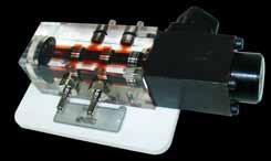
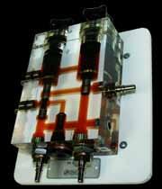
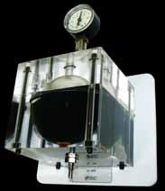
3 HYDROMODEL-200 HYDROMODEL Transparent Hydraulics - Electro-hydraulics HYDROMODEL-200 meets training needs for technology related to hydraulic components in a very visual way. The parts are made up of a transparent methacrylate body with internal industrial metal parts. Using this system, it is possible to see inside the components as they operate, becoming familiar with them and understanding how they work. Hermetic connections The hoses, as well as the different devices, are connected to each other with a system of quick-fit self-sealing connectors NW4 1/8. This system guarantees a maximum level of fluid integrity with ZERO LEAKAGE even during connection/disconnection operations. Each component includes a fixing system to aid quick and simple preparation of practical exercises. Fixing to the panel Kits HYDROMODEL-200 has 3 standard kits defined to cover training demands at different educational levels. Users can configure personalised sets to meet their own requirements or add to previously purchased equipment. SAI9500 SAI9501 SAI9502 Standard KITS MOD-201: Transparent hydraulic level I kit MOD-202: Transparent hydraulic level II kit MOD-203: Transparent electro-hydraulic kit training@smctraining.com 106
.")

 Hydraulics / electrohydraulics (SMC-111) *See elearning-200 chapter for more information. Tech docum.")
4 HYDROMODEL With this system you could... HYDROMODEL-200 comes up with different practical activities targeting skills in the technologies featuring in the table (below). TECHNOLOGIES elearning-200 Find out more about the theory behind the technologies developed in HYDROMODEL-200 with our elearning-200 courses. SKILLS Analysis Troubleshoot. Designing Related elearning-200 courses Introduction to electricity (SMC-102) DC electricity (SMC-103) AC electricity (SMC-104) Solid state (SMC-105) Sensors technology (SMC-108) Hydraulics / electrohydraulics (SMC-111) *See elearning-200 chapter for more information. Tech docum. creation Installation and assembly Tech docum. understanding Operation This shows how the HYDROMODEL-200 is suitable to develop skills in the specific technology. This shows that HYDROMODEL-200 can help develop skills in the specific technology even though there are other more appropriate products in the range. HYDROMODEL


5 HYDROMODEL-200 HYDROMODEL Extra equipment There are other products in the range to complement HYDROMODEL-200. autosim-200 autosim-200 is software that can design and simulate pneumatic, electro-pneumatic, hydraulic circuits, etc. It is also used for programming them plus monitoring and control of pre-defined 2D and 3D models. *See autosim-200 chapter for more information. HYDROMODEL Complete laboratory Discover our proposal for laboratories and the best combination of the HYDROMODEL-200 and other accessories in the chapter Product packs. HYDROMODEL Configuration Getting the right HYDROMODEL-200 configuration is as easy as: 1.- Select the panel and the necessary extras. Steps to follow 2.- Select the chosen standard kits or a personalised configuration. 3.- In the event of preferring a personalised configuration, select the references chosen for the composition. training@smctraining.com 108
6 HYDROMODEL Standard kits KITS Ref. Description Actuators SAI9412 Double acting cylinder 1 SAI9419 Single acting cylinder 1 Distribution valves SAI9413 4/2 directional control valve. Manually operated 1 SAI9431 4/2 solenoid valve, spring return 1 SAI9440 4/3 solenoid valve with closed mid-position 1 Pressure control valves SAI9414 Pressure relief valve (ball valve), direct control 1 SAI way pressure relief valve, with damping 1 SAI9420 Pressure reducing valve, 3 way. Direct control 1 Flow valves SAI9422 Manual shut-off valve, 2 way 1 SAI9423 Piloted check valve 1 SAI9415 One way restrictor 1 SAI9416 Two way flow control valve 1 SAI9421 One way flow control valve 1 SAI9424 Flow control valve with pressure compensation 1 Connection parts and accessories SAI9425 Set of 5 hoses 1 SAI9408 Set of 10 hoses 1 SAI connection distributor on manifold 1 SAI connection divider 1 SAI9406 Cross distributor with pressure gauge 1 Control modules, sensors and electrical accessories SAI9040 Power supply 1 SAI9042 Set of pushbuttons 1 SAI9041 Set of 3 relays 1 SAI9231-R Electric end of stroke (right) 1 SAI9231-L Electric end of stroke (left) 1 SAI9272 Set of connectors + cable for solenoids 1 SAI9046 Set of cables with electric connector 4 mm 1 Didactic support SAI9496 User s and practical manual 1 1 1! DON T FORGET TO ADD AN ASSEMBLY PANEL, HYDRAULIC UNIT AND EXTRAS SAI2064 Vertical mounting panel for 2 work posts SAI2065 Rolling table with twin-post SAI9410 Portable hydraulic pump for transparent hydraulic SAI2074 Storage drawer blocks for rolling table with lock 109 HYDROMODEL-200


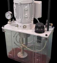
 - - Single-phase motor. Start - stop switch. Filter cap and filter.")

7 HYDROMODEL-200 HYDROMODEL Customized kits The available hydraulic and electro-hydraulic components are listed below, by category. Assembly panel, hydraulic unit and extras --External dimensions: 1150x760x410mm*. Allows work to be carried out on both sides, optimizing investment and space. *Other dimensions available on request. SAI Vertical mounting panel for 2 work posts SAI Rolling table with twin-post The entire rolling frame system may be disassembled for transportation. -The vertical panel means you can work on both sides. Panel dimensions: 1150x760x25mm - It has a work-top for horizontal work, 1200x800mm. The lower section features a 1200x600mm metal shelf containing the component storage drawers block, the portable hydraulic pump, etc. 4 wheel support, 2 of them with brake and 2 without brake, and high loading output. Total dimensions: 1200x800x1700mm. SAI Portable hydraulic pump for transparent hydraulic --Transparent tank holding 6 litres. --Gear pump. Q= 1 l/min. --Pressure relief valve, Pmax: 10 bar. --3 quick connector couplings (P + 2T) - - Single-phase motor. Start - stop switch. Filter cap and filter. --Air bubble insertion system in the circulation oil. * Does not include oil drum. SAI9411 necessary. SAI Storage drawer blocks for rolling table with lock --Compact 4-drawer block with slide guides to house the components. --External dimensions: 500x725x650mm. --With security lock. SAI Oil with special red colouring - Specially coloured oil for using with transparent elements. - Quantity required for portable hydraulic pump. Didactic support SAI9496- User s and practical manual SAI Theoretical concepts manual training@smctraining.com 110


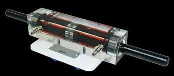
8 Actuators --ø20/ø10 x 58mm of stroke. SAI Double acting cylinder SAI Single acting cylinder --ø20/ø10 x 40mm of stroke. Spring return. --ø14/ø20/ø14 x 100mm of stroke. SAI Double rod cylinder SAI External gear motor --Two-way hydraulic motor, with external gears. --With two gears with 12 teeth and one shaft. --Two-way hydraulic motor with axial pistons. --7 metal pistons Ø12 over inclined plane. --Connections A, B and L drainage. SAI Axial piston motor SAI Vane motor --Two-way vane hydraulic motor with one shaft. 8 vanes acting on eccentric rotor. --Oscillating two-way hydraulic motor. --Angle of rotation: 180º. One shaft. SAI º rotary actuator HYDROMODEL


9 HYDROMODEL-200 Distribution valves SAI9442-2/2 directional control valve. Manually operated --Manually-operated and spring return. --With drainage. SAI9445-3/2 directional control valve. Manually operated. Seat type --Manually-operated and spring return. SAI9413-4/2 directional control valve. Manually operated --Manually-operated and spring return. SAI9446-4/2 directional control valve. Manually operated. Mechanical interlocking --Manual operation on both sides. SAI9447-4/3 directional control valve. Manually operated. Closed mid-position -Manual - operation on both sides and spring centered. SAI9449-4/3 directional control valve. Manually operated. Relieving mid-position --Manual operation on both sides and spring centered. SAI9450-4/3 directional control valve. Manually operated. P-A-B-T linked in mid-position -Manual - operation on both sides and spring centered. SAI9431-4/2 solenoid valve, spring return --Coil-operated and spring return. Low consumption coil (12w). *Connector for SAI9272 coil required. training@smctraining.com 112
10 SAI9482-4/2 solenoid valve with mechanical interlocking --Bistable. Coil-operated on both sides. Low consumption coil (12w). *Connector for SAI9272 coil required. SAI9440-4/3 solenoid valve with closed mid-position --Coil-operated on both sides and spring centered. Low consumption coil (12w). *Connector for SAI9272 coil required. SAI9483-4/3 solenoid valve. A-B-T linked in mid-position --Bistable. Coil-operated on both sides. Low consumption coil (12w). *Connector for SAI9272 coil required. SAI9484-4/3 solenoid valve. A-B-P linked in mid-position --Bistable. Coil-operated on both sides. Low consumption coil (12w). *Connector for SAI9272 coil required. SAI9485-4/3 solenoid valve. A-B-P-T linked in mid-position --Bistable. Coil-operated on both sides. Low consumption coil (12w). *Connector for SAI9272 coil required. SAI9403-4/3 proportional directional control valve, direct control. --Distributor valve 4/3 with gradual opening, depending on the value of the electrical control signal. --A, B and P connected in mid-position. T closed. --Coil-operated on both sides. Spring centered. 24Vcc / I nominal: 0.8A coils. *Connector for SAI9303 coil required. SAI9404-4/3 proportional directional control valve. --Distributor valve 4/3 with gradual opening, depending on the value of the electrical control signal, with a principal stage and another pilot stage. --Pilot-operated. External pilots X and Y. Spring centered. A, B and P connected in mid-position. T closed. --Coil-operated on both sides. 24Vcc / I nominal: 0.8A coils. *Connector for SAI9303 coil required. HYDROMODEL


11 HYDROMODEL-200 Pressure control valves SAI Proportional pressure relief valve, direct control --Regulates the maximum pressure value at a point using an electric control signal. --Coil-operated 24Vcc / I nominal: 0.8A. *Connector for SAI9303 coil required. SAI Pressure relief valve (ball valve), direct control --It enables the maximum pressure value at the input to be adjusted, unloading to the tank from the adjusted value. --Manual adjustment using the twist handle. SAI way pressure relief valve, with damping --Opens the oil flow when the preset pressure value is reached at the input. --Direct control. Manual adjustment by rotary knob. SAI Pressure reducing valve, 3 way. Direct control --It enables the pressure value at the output, at A, to be adjusted. --Manual adjustment by rotary knob. SAI Discharge valve SAI Pressure relief valve. Pilot operated --Two-stage limiter valve, one pilot and the and other principal It can work as a sequence valve, opening from P to T when P reaches the pressure value set. --Manual regulation by rotary knob. --Opens the oil flow when the preset pressure value is reached at the pilot. --Discharge valve by external pilot. --Manual regulation by rotary knob. --Manual adjustment by two rotary knobs. --Comprised of a circuit of two adjustable limit valves and a non-return valve. --All in the same body. SAI High - Low pressure circuit training@smctraining.com 114

12 Flow valves SAI Manual shut-off valve, 2 way SAI One way restrictor SAI Proportional flow control valve with pressure compensation --Coil-operated 24Vcc / I nominal: 0.8A *Connector for SAI9303 coil required. --Opens or closes the oil flow with an activation lever. --Manual rotary actuation. SAI Piloted check valve --Normally it allows the oil to pass in one direction only, but it does it in both directions when there is pressure in the pilot connection. --It enables the oil to flow on one direction only. SAI Two way flow control valve --It enables the oil flow in both directions to be adjusted. --Two-way flow control valve, with two ports, needle. Manual adjustment by rotary knob. SAI One way flow control valve SAI Flow divider --It enables the oil flow in one direction to be adjusted and flow to be unrestricted in the opposite direction. --One-way.Manual adjustment by rotary knob. SAI Flow control valve with pressure compensation --It enables the flow to be adjusted regardless of the pressure values at the input and output. --Manual regulation by rotary knob. --Flow divider valve: it divides the inlet flow into two equal parts. SAI Circuit selector with logic function OR HYDROMODEL
13 HYDROMODEL-200 Connection parts and accessories --Set of 5 transparent polyurethane tubes. 520 mm length. SAI Set of 5 hoses SAI Set of 10 hoses --Set of 10 transparent polyurethane tubes. 520 mm length: 6 units. 350 mm length: 4 units. SAI connection distributor on manifold SAI connection divider --With three self-sealing plugs and 1 socket. SAI Cross distributor with pressure gauge --Distributor with 3 connections with pressure gauge from 0 to 16 bar. --With two self-sealing plugs and 1 socket. SAI Pressure gauge without container --Without box or scale for viewing the internal mechanism. --With one self-sealing plug and one socket. SAI Pressure filter with clogging indicator --Oil filter to fit at the high pressure input of the user circuit. --Potential-free output by switched contact. SAI Piston accumulator --Load pressure (nitrogen): 4 bar. --Load pressure (nitrogen): 4 bar. SAI Diaphragm accumulator training@smctraining.com 116

. --Indication on screen of light intensity proportional to the intensity value. --Voltage input 110V - 240VAC.")


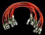
14 Control modules, sensors and electrical accessories SAI Power supply module for two proportional coils --Potentiometer for controlling the output intensity to coils a or b. --I max. = 0.9 A per coil. --Overload electronic internal protection. --Dither frequency on/off switch and Dither frequency value adjustment. --2 ammeters for displaying the current via coils a or b. SAI Set of connectors for proportional coils --Connectors with LED indicators (screen type). Long. 1.5 m. --It includes 2 units (1 grey connector and 1 black connector). --Indication on screen of light intensity proportional to the intensity value. --Voltage input 110V - 240VAC. --Output: 24VDC / 5A. --Short-circuit protection. --Input switch and LED display. --Built-in power cable. --4 mm female electrical safety connectors. --Insulating box with screen printed lid. SAI Set of pushbuttons --2 pushbuttons with spring return. --2-position selector. --4 mm female electrical safety connectors. --Insulating box with screen printed lid. SAI Power supply SAI Set of 3 relays --It includes three relays with coil 24V and 4 switchable contacts. --LED activated relay display. --4 mm female electrical safety connectors. --Insulating box with screen printed lid. SAI9231-R / SAI9231-L - Electric end of stroke (right / left) --Retractable roller driven. --R=right. L=left. --1 contact NO.1 contact NC. --Transparent body and roller with reversible position. --4 mm female safety connectors. SAI Set of connectors + cable for solenoids --Male connectors 4 mm. Cable 1.5 m. --Ready to connect in solenoid vale coils. --It includes 3 units (1 black connector and 2 grey connectors). --LED indicators. SAI Set of cables with electric connector 4 mm --5 red cables 1.5 m yellow cables 0.5 m. --5 black cables 1 m. --5 blue cables 0.25 m. HYDROMODEL
HYDROTRAINER-200 Hydraulics - Electro-hydraulics
 HYDROTRAINER-200 Hydraulics - Electro-hydraulics Hydraulics and electro-hydraulics within your reach www.smctraining.com training@smctraining.com 80 Develop the SKILLS... Analysis Troubleshooting Implements
HYDROTRAINER-200 Hydraulics - Electro-hydraulics
 HYDROTRAINER-200 Hydraulics - Electro-hydraulics Hydraulics and electro-hydraulics within your reach Why HYDROTRAINER-200? All components included are industrial which guarantees real learning and future
PNEUMATE-200 Your mate in Pneumatics!
 PNEUMATE-200 Your mate in Pneumatics! The compact trainer to help users discover more about pneumatic and electro-pneumatic technologies. www.smctraining.com training@smctraining.com 40 Develop the SKILLS...
PNEUTRAINER-400 Pneumatics - Electropneumatics
 PNEUTRAINER-400 Pneumatics - Electropneumatics End-to-end solution for training in pneumatics and electro-pneumatics SMC industrial systems components on panel mounting plate Implements and controls pneumatic
PNEUTRAINER-200 Pneumatics - Electro-pneumatics
 PNEUTRAINER-200 Pneumatics - Electro-pneumatics End-to-end solution for training in pneumatics and electro-pneumatics. www.smctraining.com training@smctraining.com 46 Develop the SKILLS... Analysis Troubleshooting
Didactic and technological innovation at the service of training in pneumatics and electro-pneumatics have resulted in the creation of the
 Didactic and technological innovation at the service of training in pneumatics and electro-pneumatics have resulted in the creation of the PNEUTRAINER-200 system. A fully modular system designed for the
Suggested list for the Hydraulic and Pneumatic lab Instruments Mechatronics Engineering Department School of Applied Technical Science
 Suggested list for the Hydraulic and Pneumatic lab Instruments Mechatronics Engineering Department School of Applied Technical Science Pneumatic and Electro-pneumatic components: No. EQUIPMENTS operating
Subject: Pneumatic Training Kit with portable Air Compressor
 MSME TOOL ROOM: HYDERABAD (CENTRAL INSTITUTE OF TOOL DESIGN) Balanagar, Hyderabad 500 037 TEL.NO.23772747, 23776168 FAX No.0-4023772658 E-mail:citdpurchase@citdindia.org Visit us: www.citdindia.org. TENDER
Test. What type of cylinder would you use? A. Single-acting cylinder B. Double-acting cylinder Answer:
 Test This test allows you to establish whether your basic knowledge of pneumatic controls is sufficient for you to attend the advanced course P or whether you should attend the basic level course P. The
Module 5: Valves. CDX Diesel Hydraulics. Terms and Definitions. Categories of Valves. Types of Pressure Control Valves
 Terms and Definitions Categories of Valves Types of Pressure Control Valves Types and Operation of Pressure Relief Valves Operation of an Unloading Valve Operation of a Sequencing Valve Operation of a
BASIC PNEUMATIC & ELECTROPNEUMATIC TRAINING SYSTEM
 BASIC PNEUMATIC & ELECTROPNEUMATIC TRAINING SYSTEM UCTECH has designed a comprehensive range of specialised training packages and products for pneumatic and electro-pneumatic training using well-known
Test Which component has the highest Energy Density? A. Accumulator. B. Battery. C. Capacitor. D. Spring.
 Test 1 1. Which statement is True? A. Pneumatic systems are more suitable than hydraulic systems to drive powerful machines. B. Mechanical systems transfer energy for longer distances than hydraulic systems.
Introduction. Pre-Lab
 The University Of Jordan School of Engineering Mechatronics Engineering Department Fluid Power Engineering Lab Experiments No.2 Pneumatic Control of a Double-acting Cylinder Objective: Students will be
Learning System for Automation and Communications. Electropneumatics. Workbook Basic Level S1 K1 K1 Y1
 Learning System for Automation and Communications Electropneumatics Workbook Basic Level 1 2 3 S1 K1 K1 S2 K1 094005 Order no. 094005 Description: TEACHW.E-PNEUM. Designation: D.S201-C-GB Edition: 08/1993
Actuators and directional control valves
 Actuators and directional control valves 1. Differentiate between the main types of directional control valves. 2. Demonstrate the function and uses of 3/2 way valve, push button actuated. 3. Demonstrate
Electrohydraulics Advanced Level Workbook TP 602
 Electrohydraulics Advanced Level Workbook TP 602 Festo Didactic 094471 en Authorised applications and liability The Learning System for Automation and Communication has been developed and prepared exclusively
Z1 B1 B2 Z2 B3 B4. Steuerteil + 24 V. Leistungsteil K1 K2 K1 K2. Practice for Professionals Electropneumatics Trainee s manual. Version 1.
 04 Z1 B1 B2 04 Z2 B3 B4 31 14 Y1 12 4 2 5 3 1 15 31 14 Y2 12 4 2 5 3 1 15 Steuerteil + 24 V B1 S0 K1 B2 K2 B4 K3 B3 Leistungsteil 1 2 3 4 5 6 7 8 9 K4 K1 K2 0V K1 K2 K1 K3 K2 K4 K3 Y1 K3 Y2 Practice for
SAP E & C ADVANCED CUSTOMIZED ELECTRO PNEUMATIC TRAINER (FOR ITI) (PRODUCT CODE: SAP 20B-I)
 (PRODUCT CODE: SAP 20B-I)") The Advanced Customized Electro Pneumatic Trainer (SAP 20B-I) is capable of being used to demonstrate the design, construction and application of electro-pneumatic components and circuits. Objectives:-
The Advanced Customized Electro Pneumatic Trainer (SAP 20B-I) is capable of being used to demonstrate the design, construction and application of electro-pneumatic components and circuits. Objectives:-
Transmitters: Relay Valve VR4151/4152
 Relay Valve VR4151/4152 Appropriate output sequences are affected according to the signal received from the mechanical valve. VR4151 VR4152 Precautions Be sure to read before handling. Refer to pages 5-11-2
TECHNICAL PAPER 1002 FT. WORTH, TEXAS REPORT X ORDER
 I. REFERENCE: 1 30 [1] Snow Engineering Co. Drawing 80504 Sheet 21, Hydraulic Schematic [2] Snow Engineering Co. Drawing 60445, Sheet 21 Control Logic Flow Chart [3] Snow Engineering Co. Drawing 80577,
Exercise 3-1. Basic Hydraulic Circuit EXERCISE OBJECTIVE DISCUSSION OUTLINE DISCUSSION. Complete hydraulic circuit
 Exercise 3-1 Basic Hydraulic Circuit EXERCISE OBJECTIVE When you have completed this exercise, you will be familiar with the hydraulic schematic and components of the nacelle trainer. You will identify
JIS symbols used in this catalog are old symbols following JISB0125-1: Refer to JISB0125-1: 2007 or JFPS2011: 2006 for new symbols.
 symbol s used in this catalog are old symbols following JISB0-: 00. Refer to JISB0-: 007 or JFPS0: 006 for new symbols. Page. Element of symbol. Line and port. Directional control valve. Pressure control
Automatic Control System PS Pneumatic Training System. Features
 Pneumatic Training System It is well known that Factory utomation is an indispensable measure to reduce labor cost, improve production efficiency and achieve higher product quality, which is widely adopted
: Automation Laboratory 1
 Table A.1 shows elements found in FluidSIM library with a brief description for each of them. Compressed air supply The compressed air supply provides the needed compressed air. It contains a pressure
Special valves. Series. Solenoids. IP65 (with connector) Zones 1, 21 II 2 G II 2 GD EEx me IP64. Aluminium. Operation. Page no. EEx me IP65.
 Zones 1, 21 II 2 G II 2 GD EEx me IP64. Aluminium. Operation. Page no. EEx me IP65.") Special valves Operation Series Page no. Function 2/2 Body material Brass Aluminium Solenoids IP Protection class Explosion proof class IP65 (with connector) Zones 1, 21 II 2 G II 2 GD EEx me IP64 EEx
Special valves Operation Series Page no. Function 2/2 Body material Brass Aluminium Solenoids IP Protection class Explosion proof class IP65 (with connector) Zones 1, 21 II 2 G II 2 GD EEx me IP64 EEx
ADVANCED CUSTOMIZED ELECTRO PNEUMATIC TRAINER (PRODUCT CODE: SAP 20B)
") The Advanced Customized Electro Pneumatic Trainer (SAP 20B) is capable of being used to demonstrate the design, construction and application of electro-pneumatic components and circuits. Objectives:- The
The Advanced Customized Electro Pneumatic Trainer (SAP 20B) is capable of being used to demonstrate the design, construction and application of electro-pneumatic components and circuits. Objectives:- The
ESCONDIDO FIRE DEPT TRAINING MANUAL Section DRIVER OPERATOR Page 1 of 13 Pumps and Accessory Equipment Revised
 DRIVER OPERATOR Page 1 of 13 PUMPS AND ACCESSORY EQUIPMENT Pumps are designed for many different purposes. In order to understand the proper application and operation of a pump in a given situation, firefighters
2. Hydraulic Valves, Actuators and Accessories. 24 Marks
 2. Hydraulic Valves, Actuators and Accessories 24 Marks Co related to chapter 602.2 Describe working principle of various components used in hydraulic & pneumatic systems. 602.3 Choose valves, actuators
TUTORIAL QUESTIONS FOR COURSE TEP 4195
 TUTORIL QUESTIONS FOR COURSE TEP 4195 Data: Hydraulic Oil Density 870 kg/m 3 bsolute viscosity 0.03 Ns/m 2 Spool valve discharge coefficient 0.62. 1) hydrostatic transmission has a variable displacement
Electro Pneumatic Workbench Scientech 2470
 Scientech 2470 Electro Pneumatic Workbench is designed to demonstrate the design, construction and application of Pneumatic components and circuits. It integrates PLC technology to build Hybrid Industrial
1 Pneumatics. Transmitters VR4151 VR4152 VR1210 VR1220 VR1210F VR1220F VR1211F VR VR3200 VR3201 VR3100 VR3110
 Best 1 Pneumatics Transmitters Relay valve P. 1900 Side piping: 30 x 53 x 91 Bottom piping: 30 x 8 x 91 VR151 VR152 Effective area (mm 2 ) Number of ports Function 7 5 Metal Spool Shuttle valve P. 1902
walton TEMPERATURE CONTROL SYSTEMS Pneumatically Operated (Rotary)
") walton TEMPERATURE CONTROL SYSTEMS Pneumatically Operated (Rotary) WALTON ENGINEERING CO. LTD. 61 London Road St Albans Hertfordshire AL1 1LJ England Telephone +44 (0)1727 855616 Fax +44 (0)1727 841145
walton TEMPERATURE CONTROL SYSTEMS Pneumatically Operated (Rotary) WALTON ENGINEERING CO. LTD. 61 London Road St Albans Hertfordshire AL1 1LJ England Telephone +44 (0)1727 855616 Fax +44 (0)1727 841145
CURRICULUM BOSCH-REXROTH (CENTRE OF EXCELLENCE) GANPAT UNIVERSITY
 GANPAT UNIVERSITY") ANNEXURE - A CURRICULUM BOSCH-REXROTH (CENTRE OF EXCELLENCE) Host Institute: GANPAT UNIVERSITY Contents of Basic Industrial Pneumatics -----------------------------------------------------------------------------------------------------------------
ANNEXURE - A CURRICULUM BOSCH-REXROTH (CENTRE OF EXCELLENCE) Host Institute: GANPAT UNIVERSITY Contents of Basic Industrial Pneumatics -----------------------------------------------------------------------------------------------------------------
2/2 Pressure operated valves
 Operation Series Page no. Function 2/2 3/2 Body material Stainless steel Brass Solenoids IP Protection class IP65 (with connector) Explosion proof class Zones 1, 21 II 2 GD EEx m IP67 II 2 G EEx me IP54
2/2-way Quarter-Turn Ball Valve in stainless steel with pneumatic rotary actuator, DN 10-50
 2/2-way Quarter-Turn Ball Valve in stainless steel with pneumatic rotary actuator, 10-50 (2652) (2655) 2 or ball valve Pneumatic actuator Compact design Visual position indicator Types 2652/2655 can be
[You may download this article at: https://fluidsys.org/downloads/ ]
![[You may download this article at: https://fluidsys.org/downloads/ ]](/thumbs/75/72588514.jpg "[You may download this article at: https://fluidsys.org/downloads/ ]") Fluidsys Training Centre, Bangalore offers an extensive range of skill-based and industry-relevant courses in the field of Pneumatics and Hydraulics. For more details, please visit the website: https://fluidsys.org
Fluidsys Training Centre, Bangalore offers an extensive range of skill-based and industry-relevant courses in the field of Pneumatics and Hydraulics. For more details, please visit the website: https://fluidsys.org
Electro Pneumatic WorkStation Scientech 2470
 Electro Pneumatic WorkStation is designed to demonstrate the design, construction and application of Pneumatic components and circuits. It integrates PLC technology to build Hybrid Industrial Automation
Hydraulic and Electro-Hydraulic Application AE-HD
 Engineering and Technical Teaching Equipment Hydraulic and Electro-Hydraulic Application AE-HD AE-HD. Hydraulic and Electro-Hydraulic Application INTRODUCTION Hydraulics is the technology that employs
Exercise 3-1. Basic Hydraulic Circuit EXERCISE OBJECTIVE DISCUSSION OUTLINE DISCUSSION. Complete hydraulic circuit
 Exercise 3-1 Basic Hydraulic Circuit EXERCISE OBJECTIVE When you have completed this exercise, you will be familiar with the hydraulic schematic and components of the nacelle trainer. You will identify
N-02 MAINTENANCE MECHANIC TRAINING SKILL DEVELOPMENT GUIDE
 N-02 MAINTENANCE MECHANIC TRAINING SKILL DEVELOPMENT GUIDE Duty N: System Troubleshooting N-02: Troubleshoot Pneumatic System Issued 6/01/98 Task Preview Troubleshoot Pneumatic System The Maintenance Mechanic,
Pneumatic Manual 2008
 Pneumatic Manual 2008 The Advantages of Using Pneumatics in 2008 Fluid power technology encompasses both hydraulics and pneumatics. Hydraulic applications use pressurized fluids, mostly oil, while pneumatic
Training systems for hydraulics. Edition:
 Training systems for hydraulics Edition: 05.2017 2 Training systems for hydraulics Training systems for hydraulics 3 The 4 Learning topics 7 Term definition 11 Overview of the learning topics 12 Learning
Industrial Mechanic (Millwright) Level 3
 Level 3") Industrial Mechanic (Millwright) Level 3 Rev. September 2005 Industrial Mechanic (Millwright) Unit: G5 Prime Movers I Diesel 1 Level: Duration: Three 60 hours Theory: 20 hours Practical: 40 hours Overview:
Industrial Mechanic (Millwright) Level 3 Rev. September 2005 Industrial Mechanic (Millwright) Unit: G5 Prime Movers I Diesel 1 Level: Duration: Three 60 hours Theory: 20 hours Practical: 40 hours Overview:
ELECTRIC CARTRIDGES ELECTRO-PROPORTIONAL VALVES
 ELECTRIC CARTRIDGES ELECTRO-PROPORTIONAL VALVES 6. 9 ELECTRO-PROPORTIONAL VALVES ELECTRIC CARTRIDGES ELECTRO-PROPORTIONAL VALVES In the follow of this chapter, NEM presents the electro-proportional flow
Input, Control and Processing elements
 PNEUMATIC & HYDRAULIC SYSTEMS CHAPTER FIVE Input, Control and Processing elements Dr. Ibrahim Naimi Valves The function of valves is to control the fluid path or the pressure or the flow rate. Depending
KAM IAS ISOKINETIC AUTOMATIC SAMPLER. User Manual IASMANUAL-0513 KAM CONTROLS, INC Ann Arbor Drive Houston, Texas USA
 An ISO 900 certified company TEL + 73 784-0000 FAX + 73 784-000 Email Sales@Kam.com KAM IAS ISOKINETIC AUTOMATIC SAMPLER PER API 8.2, ASTM D477 AND ISO 37 User Manual IASMANUAL-053 3939 Ann Arbor Drive
Marine Engineering Exam Resource Review of Hydraulics
 1. What is Pascal s law? Pressure confined on a confined fluid will transmit the pressure in all directions and act with equal force on all areas at right angles. 2. How does the law pertain to hydraulics?
ELECTROPNEUMATIC POSITIONING SYSTEM CONTROL WITH THE LEGENDARY LOGO! PLC
 ELECTROPNEUMATIC POSITIONING SYSTEM CONTROL WITH THE LEGENDARY LOGO! PLC G. Kozoris Dept. of Automation Engineering, PUAS, Athens, Greece M. Papoutsidakis Dept. of Automation Engineering, PUAS, Athens,
Winding technology, pneumatically actuated tension brakes
 Winding technology, pneumatically actuated tension brakes Pneumatically actuated tension brakes with internally ventilated brake disc Series 0454 Operation 7.03.00 Properties, areas of application 7.03.00
100 to 400 MPa Series
 100 to 400 Series 100 Pumps 202 Accessories 203 200 Single-Acting Cylinders 204 Double-Acting Cylinders 205 Manual Pumps 206 SMP-200 207 Electric Pumps 208 Special Pumps 209 Valves 210 to 212 Pressure
2005 FIRST Pneumatic Manual
 2005 FIRST Pneumatic Manual 1/6/2005 The Advantages of Using Pneumatics in 2005 Fluid power technology encompasses both hydraulics and pneumatics. Hydraulic applications use pressurized fluids, mostly
Push buttons are of two types i) Momentary push button ii) Maintained contact or detent push button
 Momentary push button ii) Maintained contact or detent push button") ELECTRO-PNEUMATIC Push button switches A push button is a switch used to close or open an electric control circuit. They are primarily used for starting and stopping of operation of machinery. This causes
ELECTRO-PNEUMATIC Push button switches A push button is a switch used to close or open an electric control circuit. They are primarily used for starting and stopping of operation of machinery. This causes
Introduction. Installation. Maintenance. Bill of Materials
 Table of Contents Introduction Specitications... 3 Operation... 4 Installation New Installations... 6 Retrofit Installations... 6 Flow Control Switch... 7 Dimensions... 8 E-7 Valve... 28 E-7 Valve with
V5 60 LPM SECTIONAL SPOOL VALVE
 V5 60 LPM SECTIONAL SPOOL VALVE 37 V5 60 LPM SECTIONAL SPOOL VALVE Description A low profile sectional spool valve, lever, solenoid or cable operated. Suitable for open or closed centre circuits. Spool
Section 6.1. Implement Circuit - General System. General: TF Configuration TB Configurations Implement Control Valve:
 Section 6.1 Implement Circuit - General System General: TF Configuration... 6.1.3 TB Configurations... 6.1.5 Implement Pump Breakdown... 6.1.6 Operational Description: General... 6.1.7 Compensator Control...
Suction Spares and Accessories 2009
 MUL91600101 Black Rubber Feet for Machined Base Plates, (Pack of 5) MUL8150038 Black Rubber Feet for Machined Base Plates, (Pack of 4) b MUL94004000 Illuminated Green Rocker Switch (L30mm x W25mm x D30mm)
HOW THE SPRAGUE PRODUCTS BOOSTERS WORK
 SUPERCHARGE SHOP AIR OR BOTTLED GAS WITH SPRAGUE PRODUCTS GAS BOOSTER Sprague Products pneumatic boosters offer a cost effective way to compress shop air or bottled gas to meet various requirements for
Job Sheet 5 Hydraulic Unit Circuit
 Job Sheet 5 Hydraulic Unit Circuit The key components involved in the cylinder piston rod actuation (solenoid valves SV1, SV2, SV3A, and SV3B) are within the core components of the hydraulic unit of the
Basic Hydraulics. Module 2: Actuators and directional control valves. Curriculum Development Unit PREPARED BY. August 2013
 Basic Hydraulics Module 2: Actuators and directional control valves PREPARED BY Curriculum Development Unit August 2013 Applied Technology High Schools, 2013 ATM-312 Basic Hydraulics Module 2: Actuators
Pneumatics Electropneumatics
 Training systems for basic and future oriented education in natural science and engineering Pneumatics Electropneumatics Experimental Panel and Module System 07 / 2003 Contents Experimental panel system..........................
Chapter 10: Valves for Pipe Mounting
 Contents Chapter : Valves for Pipe Mounting Series Description Size Body Page DIN / ISO 1/8 1/4 3/8 1/2 3/4 1 1¼ 1½ 2 L-port T-port Pressure valves, manual operation R4V R4R Pressure relief function Pressure
FLUID POWER P&IDs. IDENTIFY the symbols used on engineering fluid power drawings for the following components:
 FLUID POWER P&IDs Fluid power diagrams and schematics require an independent review because they use a unique set of symbols and conventions. EO 1.11 IDENTIFY the symbols used on engineering fluid power
Exercise 5-1. Primary Resistor Starters EXERCISE OBJECTIVE DISCUSSION. Understand how primary resistor starters operate.
 Exercise 5-1 Primary Resistor Starters EXERCISE OBJECTIVE Understand how primary resistor starters operate. DISCUSSION High starting torque can result in sudden acceleration and damage to the driven machinery.
Safety for Hydraulics
 Safety for Hydraulics Compac-type Proportional Valves Reference: 301-P-9050025-EN-04 Issue: 08.2015 1/30 Contents Page 1 Functional description... 4 1.1 The load check-back signal... 4 1.2 The flow characteristics...
V Series AXIAL PISTON PUMP ORDER CODE
 V Series AXIAL PISTON PUMP ORDER CODE V A 1 R B S - A D X A 1 Customers demand Pump Series V Links Type (only V -18): none - Standard A - SAE A bolts Ma. (cm 3 /n):, 18, 3,, 38, 4,, 7 Pump Control Type
Servo and Proportional Valves
 Servo and Proportional Valves Servo and proportional valves are used to precisely control the position or speed of an actuator. The valves are different internally but perform the same function. A servo
J1 Plug Pin Identification
 D D8 D D D D ART_8 J 8 D D0 R R R R TB 80 D D D D D D J Plug Pin Identification PIN # WIRE # SIGNAL FUNCTION 0 INPUT Drive Reverse INPUT Drive Forward OUTPUT Brake, Decel Valve signal 8 INPUT Steer Left
Contents. Quality Hydraulic Components from the Webtec Range. Introduction. Hydraulic Flow Control Valves
 Quality Hydraulic Components from the Webtec Range Contents Description Section Webtec Products Ltd Introduction 1 Hydraulic Flow Control Valves 2 Hydraulic Directional Control Valves and Check Valves
Operation and Maintenance Manual
 BM / BMA Hydrometers ½ Operation and Maintenance Manual i This manual is intended for use by the users of this equipment. The information contained herein is the property of the Arad Ltd. Dalia and may
J1 Plug Pin Identification
 D5 D8 D7 D4 D5 D ART_8 J 4 8 D D0 7 R R R R4 TB 80 D D D D4 D D J Plug Pin Identification PIN # WIRE # SIGNAL FUNCTION 0 INPUT Drive Reverse INPUT Drive Forward OUTPUT Brake, Decel Valve signal 4 8 INPUT
Variable displacement axial piston pumps,
 Variable displacement axial piston pumps, Edition: 04/04.2000 Replaces: 04/10.99 DISPLACEMENTS From To PRESSURE Max. continuous Max. intermittent Max. peak 29 cm 3 /rev 73 cm 3 /rev 280 bar 315 bar 350
Definitions of Technical Terms
 Definitions of Technical Terms ABSOLUTE A measure having as it s zero point of base the complete absence of the entity being measured. ABSOLUTE PRESSURE A pressure scale with zero point at a perfect vacuum.
three different ways, so it is important to be aware of how flow is to be specified
 Flow-control valves Flow-control valves include simple s to sophisticated closed-loop electrohydraulic valves that automatically adjust to variations in pressure and temperature. The purpose of flow control
A system of lubricant dispensing devices (oil or grease) connected by piping to a central pumping unit that is operated automatically or manually.
 connected by piping to a central pumping unit that is operated automatically or manually.") Air/Oil Systems: A lubrication system in which small measured quantities of oil are introduced into an air/oil mixing device which is connected to a lube line that terminates at a bearing, or other lubrication
Air/Oil Systems: A lubrication system in which small measured quantities of oil are introduced into an air/oil mixing device which is connected to a lube line that terminates at a bearing, or other lubrication
Pneumatic and Electro-Pneumatic Application AE-NS INTRODUCTION
 Pneumatic and Electro-Pneumatic Application Engineering and Technical Teaching Equipment AE-NS AE-NS. Pneumatic and Electro-Pneumatic Application INTRODUCTION Pneumatics is the technology that employs
Series VCHR. Direct Operated Regulator for 6.0 MPa (Relieving Type) Service life: 10 million cycles. How to Order
 Service life: 10 million cycles. How to Order") Direct Operated Regulator for (Relieving Type) Series Service life: 0 million cycles Using NSF-H-certified grease on the guide ring (sliding) part. Improved durability under a high environment with a polyurethane
Direct Operated Regulator for (Relieving Type) Series Service life: 0 million cycles Using NSF-H-certified grease on the guide ring (sliding) part. Improved durability under a high environment with a polyurethane
Diaphragm Valve MV 309
 Diaphragm Valve MV 309 Benefits compact designed pneumtically operated valve standard with visual position indicator common installation length air connections acc. to NAMUR Application chemical and industrial
Basic Hydraulics and Pneumatics
 Basic Hydraulics and Pneumatics Module 2: Actuators and directional control valves PREPARED BY Academic Services August 2011 Applied Technology High Schools, 2011 ATM 1122 Basic Hydraulics Module 2: Actuators
ITT Conoflow Process Control Solutions
 ITT Conoflow Process Control Solutions Process Control Solutions About ITT Conoflow Under the ITT Conoflow brand, ITT is a market-leading manufacturer of Instruments and Controls for the various segments
FLUID POWER FLUID POWER EQUIPMENT TUTORIAL HYDRAULIC AND PNEUMATIC MOTORS. This work covers part of outcome 2 of the Edexcel standard module:
 FLUID POWER FLUID POWER EQUIPMENT TUTORIAL HYDRAULIC AND PNEUMATIC MOTORS This work covers part of outcome 2 of the Edexcel standard module: UNIT 21746P APPLIED PNEUMATICS AND HYDRAULICS The material needed
V Series AXIAL PISTON PUMP ORDER CODE
 V Series AXIAL PISTON PUMP ORDER CODE V 15 A 1 R B S - A 1 D X A 11 Customers demand Pump Series V Links Type (only V 15-18): none - Standard A - SAE A 2 bolts Ma. Displacement (cm 3 /n): 15, 18, 23, 25,
MONOBLOCK DIRECTIONAL CONTROL VALVES
 MONOBLOCK DIRECTIONAL CONTROL VALVES CONTENTS: RM0...... RM5...... RM40P...... RM80...... RMD90...... MRP70... Page 1/19&/19 /19...5/19 6/19...10/19 11/19...15/19 16/19&17/19 18/19&19/19 MONOBLOCK DIRECTIONAL
TUTORIAL QUESTIONS FOR THE INDUSTRIAL HYDRAULICS COURSE TEP 4205
 TUTORIAL QUESTIONS FOR THE INDUSTRIAL HYDRAULICS COURSE TEP 4205 The book for the course is Principles of Hydraulic System Design, by Peter J Chapple. Published by Coxmoor Publishing Co., UK. Available
Troubleshooting Bosch Proportional Valves
 Troubleshooting Bosch Proportional Valves An Informative Webinar Developed by GPM Hydraulic Consulting, Inc. Instructed By Copyright, 2009 GPM Hydraulic Consulting, Inc. TABLE OF CONTENTS Bosch Valves
CH.4 Basic Components of Hydraulic and Pneumatic System/16 M HAP/17522/AE5G
 Content : 4.1 Hydraulic and Pneumatic actuators. 10 Marks Hydraulic Actuators - Hydraulic cylinders (single, double acting and telescopic) construction and working, Hydraulic motors (gear and piston type)
Mechatronics. Training Systems. Pneumatics/Electro-pneumatics, PLC, Hydraulics/Electro-hydraulics, Mechanical Transmission
 Mechatronics Training Systems Pneumatics/Electro-pneumatics, PLC, Hydraulics/Electro-hydraulics, Mechanical Transmission Tutor Kits Pneumatics Trainers Hydraulics Trainers Courseware/Teachware Mechanical
Pilot Operated Pressure Relief Valve Series R5V (Denison)
") Characteristics Pilot operated pressure relief valves series R5V have a similar design to the subplate mounted R4V series. The SAE flanges allow to mount the valves directly on the outlet flanges of pumps
Characteristics Pilot operated pressure relief valves series R5V have a similar design to the subplate mounted R4V series. The SAE flanges allow to mount the valves directly on the outlet flanges of pumps
renewable energy and energy efficiency
 renewable energy and energy efficiency We provide integral equipment Alecop designs, develops and manufactures technical training equipment for engineers and technicians. Our customers range from universities
FLUID POWER FLUID POWER EQUIPMENT TUTORIAL PNEUMATIC CIRCUTS. This work covers part of outcome 3 of the Edexcel standard module:
 FLUID POWER FLUID POWER EQUIPMENT TUTORIAL PNEUMATIC CIRCUTS This work covers part of outcome 3 of the Edexcel standard module: UNIT 21746P APPLIED PNEUMATICS AND HYDRAULICS The material needed for outcome
FLUID POWER TUTORIAL HYDRAULIC PUMPS APPLIED PNEUMATICS AND HYDRAULICS H1
 FLUID POWER TUTORIAL HYDRAULIC PUMPS This work covers outcome 2 of the Edexcel standard module: APPLIED PNEUMATICS AND HYDRAULICS H1 The material needed for outcome 2 is very extensive so the tutorial
VL-VR bar. p p p. 51. Pressure bar
 VL-VR In-line valves - Regulating valves 700-1000 - 00-3000 bar Pressure 700-3000 bar FEATURES These valves provide the means to control cylinders and actuators operating at pressures of 700, 1000, 00
Exp1 Hysteresis Magnetometer
 Exp1 Hysteresis Magnetometer Object To understand magnetization and ferromagnetic hysteresis loop. Introduction The apparatus is designed for the examination of specimens in the form of a rod. The length
2/ VDMA (ISO ) 5/2-5/3-way CC CO CP. CATALOGUE > Release 8.8 CONTROL > Series 7 valves and solenoid valves GENERAL DATA
 5/2-5/3-way CC CO CP. CATALOGUE > Release 8.8 CONTROL > Series 7 valves and solenoid valves GENERAL DATA") CATALOGUE > Release 8.8 > Series 7 valves and solenoid valves Series 7 valves and solenoid valves VDMA 4563 (ISO 15407-1) 5/ - 5/3-way CC CO CP Size 6 mm (VDMA 4563-01) Size 18 mm (VDMA 4563-0) GENERAL
CATALOGUE > Release 8.8 > Series 7 valves and solenoid valves Series 7 valves and solenoid valves VDMA 4563 (ISO 15407-1) 5/ - 5/3-way CC CO CP Size 6 mm (VDMA 4563-01) Size 18 mm (VDMA 4563-0) GENERAL
Table of Contents. Table of Contents Pneumatik / Hydraulik
 Table of Contents Table of Contents Pneumatik / Hydraulik Pneumatics with UniTrain Hydraulics with UniTrain PBC / PEC Pneumatics and Electro-Pneumatics PBC Fluid power trainer pneumatics set PBC 2 Fluid
Pneumatic Systems. Module 3: Logic Operations in Electropneumatics. IAT Curriculum Unit PREPARED BY. August 2008
 Pneumatic Systems Module : Logic Operations in Electropneumatics PREPARED BY IAT Curriculum Unit August 2008 Institute of Applied Technology, 2008 2 Module : Logic Operations in Electro-pneumatics Module
SD Bendix E-10PR Retarder Control Brake Valve DESCRIPTION. OPERATION - Refer to Figure 2
 SD-03-832 Bendix E-10PR Retarder Control Brake Valve MOUNTING PLATE SUPPLY 4 PORTS ELECTRICAL AUXILIARY DESCRIPTION TREADLE RETARDER CONTROL SECTION EXHAUST DELIVERY 4 PORTS FIGURE 1 - E-10PR RETARDER
Transmitters: Relay Valve
 Relay Valve VR5/5 Series Appropriate output sequences are affected according to the signal received from the mechanical valve. It is equivalent to the auxiliary relay of an electrical system. Specifications
MF100BH (BASIC HYDRAULICS TRAINER) PARTS LIST CATALOG APRIL 2013
 PARTS LIST CATALOG APRIL 2013") MF100BH (BASIC HYDRAULICS TRAINER) PARTS LIST CATALOG APRIL 2013 MF100BH (BASIC HYDRAULICS TRAINER) PARTS LIST NOTE: Asterisk (*) in front of a part number indicates a component required to construct the
MF100BH (BASIC HYDRAULICS TRAINER) PARTS LIST CATALOG APRIL 2013 MF100BH (BASIC HYDRAULICS TRAINER) PARTS LIST NOTE: Asterisk (*) in front of a part number indicates a component required to construct the
INSTALLATION AND MAINTENANCE OF TOP LOADING ARM
 INSTALLATION AND MAINTENANCE OF TOP LOADING ARM D TABLE OF CONTENTS 1. INTRODUCTION 04 2. SPECIFICATION OF THE REDLANDS LOADING ARM 04 3. INSTALLING THE LOADING ARM 3.1. Installation Procedures 05 4.
Power Valve: Economy Valve. Standard Specifications. Model VEX55-04
 Three functions (pressure regulator, switching valve, and speed controller) are provided by a single valve. The conventional valve combination circuit has been condensed into a single valve. A large capacity