2. Hydraulic Valves, Actuators and Accessories. 24 Marks
|
|
|
- Lily Drusilla Griffith
- 5 years ago
- Views:
Transcription
1 2. Hydraulic Valves, Actuators and Accessories 24 Marks
2 Co related to chapter Describe working principle of various components used in hydraulic & pneumatic systems Choose valves, actuators and accessories required for simple hydraulic and pneumatic circuits.
3 Pressure-control valves Function Pressure-control valves are used in hydraulic systems to control actuator force (force = pressure area) and to determine and select pressure levels at which certain machine operations must occur.
4 Types of pressure control valves Pressure-relief valve. Pressure-reducing valve. Unloading valve Counterbalance valve. Pressure-sequence valve.
5 Pressure Relief valves The pressure relief valves are used to protect the hydraulic components from excessive pressure. It is normally a closed type and it opens when the pressure exceeds a specified maximum value by diverting pump flow back to the tank.
6 Schematic of direct pressure relief valve is shown in figure This type of valves has two ports; one of which is connected to the pump and another is connected to the tank. It consists of a spring chamber where poppet is placed with a spring force. Direct type of relief valve
7 Generally, the spring is adjustable to set the maximum pressure limit of the system. The poppet is held in position by combined effect of spring force and dead weight of spool. As the pressure exceeds this combined force, the poppet raises and excess fluid bypassed to the reservoir (tank). Direct type of relief valve

8 The poppet again reseats as the pressure drops below the pre-set value. A drain is also provided in the control chamber. It sends the fluid collected due to small leakage to the tank and thereby prevents the failure of the valve. Direct type of relief valve
9 Three-dimensional view of simple pressure-relief valve.

10 Compound relief valve or pilot operated relief valve

11 Compound relief valve or pilot operated relief valve
12 symbol VIDEO 1
13 Pressure Reducing Valve Sometimes a part of the system may need a lower pressure. This can be made possible by using pressure reducing valve as shown in Figure. These valves are used to limit the outlet pressure. Generally, they are used for the operation of branch circuits where the pressure may vary from the main hydraulic pressure lines. These are open type valve and have a spring chamber with an adjustable spring, a movable spool as shown in figure.
 pressure increases to the valve setting, the spool moves to the up to partially block the outlet port.")
14 A pressure-reducing valve uses a spring-loaded spool to control the downstream pressure. If the downstream pressure is below the valve setting, the fluid flows freely from the inlet to the outlet. When the outlet (downstream) pressure increases to the valve setting, the spool moves to the up to partially block the outlet port. Just enough flow is passed to the outlet to maintain its preset pressure level. If the valve closes completely, leakage past the spool causes downstream pressure to build up above the valve setting. This is prevented from occurring because a continuous bleed to the tank is permitted via a separate drain line to the tank.

15 Three-dimensional view of a pressurereducing valve and symbol VIDEO 2
16
17
18
19
20
21
22 Direction control valve Definition: A valve is a device that receives an external signal (mechanical, fluid pilot signal, electrical or electronics) to release, stop or redirect the fluid that flows through it. Function: The function of a DCV is to control the direction of fluid flow in any hydraulic system.
23 Direction control valve Rotary spool type: In this type, the spool is rotated to change the direction of fluid. It has longitudinal grooves. The rotary spools are usually manually operated. OUTLET-B VALVE BODY SPOOL INLET-A
24 Direction control valve Sliding spool type: In this type, the spool is slides to change the direction of fluid. A B
25 Check Valve The simplest DCV is a check valve. A check valve allows flow in one direction, but blocks the flow in the opposite direction. It is a two-way valve because it contains two ports. Figure 1.1 shows the graphical symbol of a check valve along with its no-flow and free-flow directions.

26 Ball type check valve In Fig. 1.2, a light spring holds the ball against the valve seat. Flow coming into the inlet pushes the ball off the seat against the light force of the spring and continues to the outlet. A very low pressure is required to hold the valve open in this direction. If the flow tries to enter from the opposite direction, the pressure pushes the ball against the seat and the flow cannot pass through.
27 VIDEO


28 Poppet check valve Figure 1.3 provides two schematic drawings showing the operation of a poppet check valve. A poppet is a specially shaped plug element held on a valve seat by a light spring. Fluid flows through the valve in the space between the seat and poppet. In the free flow direction, the fluid pressure overcomes the spring force. If the flow is attempted in the opposite direction, the fluid pressure pushes the poppet in the closed position. Therefore, no flow is permitted
29 Pilot-Operated check Valve A pilot-operated valve along with its symbol is shown in Fig This type of check valve always permits free flow in one direction but permits flow in the normally blocked opposite direction only if the pilot pressure is applied at the pilot pressure point of the valve. The check valve poppet has the pilot piston attached to the threaded poppet stem by a nut.

30 Pilot-Operated check Valve The light spring holds the poppet seated in a no-flow condition by pushing against the pilot piston. The purpose of the separate drain port is to prevent oil from creating a pressure build-up at the bottom of the piston. The dashed line in the graphical symbol represents the pilot pressure line connected to the pilot pressure port of the valve. Pilot check valves are used for locking hydraulic cylinders in position.
31 Shuttle valve A shuttle valve allows two alternate flow sources to be connected in a one-branch circuit. The valve has two inlets P1 and P2 and one outlet A. Outlet A receives flow from an inlet that is at a higher pressure. Figure 1.5 shows the operation of a shuttle valve. If the pressure at P1 is greater than that at P2, the ball slides to the right and allows P1 to send flow to outlet A. If the pressure at P2 is greater than that at P1, the ball slides to the left and P2 supplies flow to outlet A.
32 2/2 DIRECTION CONTROL VALVE: This valve has two ports and two positions of spool. The two ports are inlet port-a and outlet port-b. Sliding spool type 2/2 DCV: The figure shows a sliding spool type spring return type Normally Closed 2/2DCV. In normal position of the spool, the ports are closed; fluid cannot flow from port-a to port-b When the palm button is pressed, spool moves to open the passage from port-a to port-b. VIDEO A B
33 Rotary spool type 2/2 DCV: OUTLET-B VALVE BODY SPOOL INLET-A The figure shows a rotary spool type 2/2DCV. In first position of the spool, the ports are closed; fluid cannot flow from port-a to port-b When the spool is rotated through 90O, it opens the passage from port-a to port-b, VIDEO
34 3/2 DIRECTION CONTROL VALVE: This valve is used to operate single acting cylinders. It has three ports namely, Pump port or inlet port P, Cylinder port A and Tank port or exhaust port T. 3/2 sliding spool type valve: The figure shows spring return type sliding spool valve. It has a springloaded spool inside the valve body. In figure, it is palm-operated type of valve. A In spool position as shown in figure, there is connection from port-a to port-t. Inlet port port-p is closed. In spool position as shown in figure, there is connection from port-p to port-a. The tank port or exhaust port, that is, port-t is closed. VIDEO P T A P T
35 3/2 rotary spool valve: The figure shows a 3/2 rotary spool valve. It has rotary spool inside the valve body. The spool is rotated through 120O to operate the valve. In spool position as shown in figure, there is connection from P to A. Fluid flows from pump to single acting cylinder. Hence the cylinder extends. The tank port or exhaust port, that is, port-t is closed. When the spool is turned to 120O, that is, as shown in shown in figure, there is connection from port-a to port-t. Fluid flows from single acting cylinder to tank. Hence the cylinder retracts. The inlet port port-p is closed. VIDEO valve body A P T spool A P T
36 4/2 DIRECTION CONTROL VALVE: This valve is used to operate double acting cylinders. It has four ports namely, Pump port or inlet port P, Cylinder port A, Cylinder port B and Tank port or exhaust port T. 4/2 sliding spool valve: In spool position as shown in figure-a, there is connection from P to A and B to T. Fluid flows form pump to port-a and form port-b to tank. When the palm button is pressed, the spool position is as shown in figure-b, there is connection from P to B and A to T. Fluid flows form pump to port-b and form port-a to tank. VIDEO A P A P B B T T
37 4/2 rotary spool valve: The figure shows a 4/2 rotary spool valve. It has rotary spool inside the valve body. The spool is rotated through 90O to operate the valve. valve body T T B A A B spool P P In spool position as shown in figure-a, there is connection from P to A and B to T. Fluid flows form pump to port-a and form port-b to tank. Hence the double acting cylinder extends. When the spool is turned to 90O, that is, as shown in shown in figure-b, there is connection from P to B and A to T. Fluid flows form pump to port-b and form port-a to tank. Hence the double acting cylinder retracts. VIDEO
38 5/2 DIRECTION CONTROL VALVE: This valve is used to operate double acting cylinders. It has 5 ports namely, Pump port or inlet port P, Cylinder port A, Cylinder port B Tank port or exhaust port T1 and Tank port or exhaust port T2. 5/2 sliding spool valve: In spool position as shown in figure, there is connection from P to A and B to T2. Fluid flows form pump to port-a and form port-b to tank. Hence the double acting cylinder extends When the palm button is pressed, the spool position is as shown in figure-b, there is connection from P to B and A to T1. Fluid flows form pump to port-b and form port-a to tank. Hence the double acting cylinder retracts. A P T1 T2 B A T1 VIDEO B P T2
39 5/2 rotary spool valve: The figure shows a 5/2 rotary spool valve. It has rotary spool inside the valve body. The spool is rotated through 72O to operate the valve. T1 T1 T2 T2 valve body valve body B A B A Figure-A spool spool P Figure-B P In spool position as shown in figure-a, there is connection from P to A and B to T2. Fluid flows form pump to port-a and form port-b to tank. Hence the double acting cylinder extends. When the spool is turned to 72O, that is, as shown in shown in figure-b, there is connection from P to B and A to T1. Fluid flows form pump to port-b and form port-a to tank. Hence the double acting cylinder retracts. VIDEO
40
41 METHODS OF ACTUATION
42 METHODS OF ACTUATION
43 Types of different center positions.
44 Flow control valve Flow-control valves, as the name suggests, control the rate of flow of a fluid through a hydraulic circuit. Applications : Typical application include regulating cutting tool speeds, spindle speeds, surface grinder speeds, and the travel rate of vertically supported loads moved upward and downward by forklifts, and dump lifts.
45 Functions of Flow-Control Valves Flow-control valves have several functions, some of which are listed below: 1. Regulate the speed of linear and rotary actuators: They control the speed of piston that is dependent on the flow rate and area of the piston: 2. Regulate the power available to the sub-circuits by controlling the flow to them: 3. Proportionally divide or regulate the pump flow to various branches of the circuit: It transfers the power developed by the main pump to different sectors of the circuit to manage multiple tasks, if necessary.
46 Classification of Flow-Control Valves Flow-control valves can be classified as follows: 1. Non-pressure compensated. 2. Pressure compensated.
47 Non-Pressure-Compensated Valves Non-pressure-compensated flow-control valves are used when the system pressure is relatively constant and motoring speeds are not too critical. A non-compensated flow control passes more or less fluid as pressure increases and decreases. This is because more fluid can pass through a certain size orifice when pressure drop (pressure difference) across the orifice increases.
48 Non-Pressure-Compensated Valves The disadvantage of these valves is discussed below. The inlet pressure is the pressure from the pump that remains constant. Therefore, the variation in pressure occurs at the outlet that is defined by the work load. This implies that the flow rate depends on the work load. Hence, the speed of the piston cannot be defined accurately using non-pressure-compensated flowcontrol valves when the working load varies. This is an extremely important problem to be addressed in hydraulic circuits where the load and pressure vary constantly.
49 Non-pressure-compensated needletype flow-control valve
50 Non-pressure-compensated needletype flow-control valve Schematic diagram of non-pressure-compensated needle-type flow-control valve is shown in Fig It is the simplest type of flow-control valve. It consists of a screw (and needle) inside a tube-like structure. It has an adjustable orifice that can be used to reduce the flow in a circuit. The size of the orifice is adjusted by turning the adjustment screw that raises or lowers the needle. For a given opening position, a needle valve behaves as an orifice.
51 Non-pressure-compensated needletype flow-control valve Sometimes needle valves come with an integrated check valve for controlling the flow in one direction only. The check valve permits easy flow in the opposite direction without any restrictions. As shown in Fig. 1.4, only the flow from A to B is controlled using the needle. In the other direction (B to A), the check valve permits unrestricted fluid flow.
52 Pressure-Compensated Valves Pressure-compensated flow-control valves overcome the difficulty caused by non-pressure-compensated valves by changing the size of the orifice in relation to the changes in the system pressure. This is accomplished through a spring-loaded compensator spool that reduces the size of the orifice when pressure drop increases. Once the valve is set, the pressure compensator acts to keep the pressure drop nearly constant. It works on a kind of feedback mechanism from the outlet pressure. This keeps the flow through the orifice nearly constant.
53 Pressure-Compensated Valves
54 Pressure-Compensated Valves A pressure-compensated flow-control valve consists of a main spool and a compensator spool. The adjustment knob co trols the ai spool s position, which controls the orifice size at the outlet. The upstream pressure is delivered to the valve by the pilot line A. Similarly, the downstream pressure is ported to the right side of the compensator spool through the pilot line B.
55 We want to keep pressure drop (pressure difference on both side of knife edge orifice) is 100 to 150 psi. The compensator spool is held open by a 100- to 150-psi compression spring that sets pressure drop across the knifeedge orifice. Flow from the inlet goes through the compensating orifice, past the compensator spool, and out through the knife-edge orifice.
56 A drilled passage ports Inlet fluid to the left end of the compensator spool, which forces the spool to the right when pressure tries to go above 100 to 150 psi. After pressure reaches or goes above 100 to 150 psi, the compensator spool moves to the right and restricts flow to the knife-edge orifice flow control.
57 Pressure at the outlet is ported to the compression-spring chamber and increases the spring force. The compensator spool assures that pressure drop across the knifeedge orifice flow control stays at a constant 100 to 150 psi. With a constant pressure drop, flow stays the same regardless of inlet or outlet fluctuations.
58 Actuators Hydraulic actuators are devices used to convert pressure energy of the fluid into mechanical energy. Depending on the type of actuation, hydraulic actuators are classified as follows: 1. Linear actuator: For linear actuation (hydraulic cylinders). 2. Rotary actuator: For rotary actuation (hydraulic motor). 3. Semi-rotary actuator: For limited angle of actuation (semi-rotary actuator).
59
60 1.2 Types of Hydraulic Cylinders Hydraulic cylinders are of the following types: Single-acting cylinders. Double-acting cylinders. Telescopic cylinders. Tandem cylinders.
61 1.2.1 Single-Acting Cylinders A single-acting cylinder is simplest in design and is shown schematically in Fig.1.1. It consists of a piston inside a cylindrical housing called barrel. On one end of the piston there is a rod, which can reciprocate. At the opposite end, there is a port for the entrance and exit of oil.
62 1.2.1 Single-Acting Cylinders Single-acting cylinders produce force in one direction by hydraulic pressure acting on the piston. (Single-acting cylinders can exert a force in the extending direction only.) The return of the piston is not done hydraulically. In single-acting cylinders, retraction is done either by gravity or by a spring.
63 1.2.2 Double-Acting Cylinder There are two types of double-acting cylinders: Double-acting cylinder with a piston rod on one side. Double-acting cylinder with a piston rod on both sides.
64 Double-Acting Cylinder with a Piston Rod on One Side Figure 1.4 shows the operation of a double-acting cylinder with a piston rod on one side. To extend the cylinder, the pump flow is sent to the blank-end port as in Fig. 1.4(a). The fluid from the rod-end port returns to the reservoir. To retract the cylinder, the pump flow is sent to the rod-end port and the fluid from the blank-end port returns to the tank as in Fig.1.4(b).
65 Double-Acting Cylinder with a Piston Rod on Both Sides A double-acting cylinder with a piston rod on both sides (Fig.1.5)is a cylinder with a rod extending from both ends. This cylinder can be used in an application where work can be done by both ends of the cylinder, thereby making the cylinder more productive. Doublerod cylinders can withstand higher side loads because they have an extra bearing, one on each rod, to withstand the loading.
66 1.2.3Telescopic Cylinder A telescopic cylinder (shown in Fig. 1.6) is used when a long stroke length and a short retracted length are required. The telescopic cylinder extends in stages, each stage consisting of a sleeve that fits inside the previous stage. One application for this type of cylinder is raising a dump truck bed. Telescopic cylinders are available in both single-acting and double-acting models. They are more expensive than standard cylinders due to their more complex construction.
67 Telescopic Cylinder They generally consist of a nest of tubes and operate on the displacement principle. The tubes are supported by bearing rings, the innermost (rear) set of which have grooves or channels to allow fluid flow. The front bearing assembly on each section includes seals and wiper rings. Stop rings limit the movement of each section, thus preventing separation. When the cylinder extends, all the sections move together until the outer section is prevented from further extension by its stop ring. The remaining sections continue outstroking until the second outermost section reaches the limit of its stroke; this process continues until all sections are extended, the innermost one being the last of all.

68 Tandem cylinder A tandem cylinder, shown in Fig. 1.7, is used in applications where a large amount of force is required from a smalldiameter cylinder. Pressure is applied to both pistons, resulting in increased force because of the larger area. The drawback is that these cylinders must be longer than a standard cylinder to achieve an equal speed because flow must go to both pistons.
69
70
71
72
73 Rotary actuators-hydraulic motors Hydraulic motors are rotary actuators. However, the name rotary actuator is reserved for a particular type of unit that is limited in rotation to less than 360. A hydraulic motor is a device which converts fluid power into rotary power or converts fluid pressure into torque

74 Pumps and motors
75 Classification of Hydraulic Motors 1. Gear motors. 2. Vane motors. 3. Piston motors: A) Axial piston-type motors. B) Radial piston-type motors.

76 Gear Motors:

77 Vane motors-unbalanced type Figure 1.2 shows an unbalanced vane motor consisting of a circular chamber in which there is an eccentric rotor carrying several spring or pressureloaded vanes. Because the fluid flowing through the inlet port finds more area of vanes exposed in the upper half of the motor, it exerts more force on the upper vanes, and the rotor turns counterclockwise. Close tolerances are maintained between the vanes and ring to The displacement of a vane hydraulic motor is a function of eccentricity. The radial load on the provide high efficiencies. shaft bearing of an unbalanced vane motor is also large because all its inlet pressure is on one side of the rotor.

78 Balanced type vane motor The radial bearing load problem is eliminated in this design by using a double-lobed ring with diametrically opposite ports. Side force on one side of bearing is canceled by an equal and opposite force from the diametrically opposite pressure port. The like ports are generally connected internally so that only one inlet and one outlet port are brought outside. The balanced vane-type motor is reliable open-loop control motor but has more internal leakage than piston-type and therefore generally not used as a servo motor.
79 Swash plate piston motor In axial piston motors, the piston reciprocates parallel to the axis of the cylinder block. These motors are available with both fixed-and variable-displacement feature types. They generate torque by pressure acting on the ends of pistons reciprocating inside a cylinder block. Figure 1.4 illustrates the inline design in which the motor, drive shaft and cylinder block are centered on the same axis. Pressure acting on the ends of the piston generates a force against an angled swash plate. This causes the cylinder block to rotate with a torque that is proportional to the area of the pistons. The torque is also a function of the swash-plate angle. The inline piston motor is designed either as a fixedor a variable-displacement unit. The swash plate determines the volumetric displacement
80 Bent axis motor A bent-axis piston motor is shown in Fig.1.6. This type of motor develops torque due to pressure acting on the reciprocating piston. In this motor, the cylinder block and drive shaft mount at an angel to each other so that the force is exerted on the drive shaft flange.
81 Pipes and Pipe Fittings
82 Necessity of pipes and hoses In hydraulic system the hydraulic energy is carried by means of closed conduits/pipes. These pipes are designed to carry the high pressure fluid and to provide flexibility and strength. Fluid power lines classified as: a) Pipe (Rigid) b) Tubes ( Semi Rigid) c) Hoses (Flexible)
83 Characteristic features of Pipes They are rigid and suitable for very high pressure application. They are not generally bent. Used for permanent application. These have maximum strength out off all three pipes. These are specified by the nominal bore size and wall thickness i.e. for a given ID it can have various OD. Pipes are generally made of metals.
84 Characteristic features of Tubes They are made of comparatively flexible materials. They can be bent to any shape and are easy to work. It can be used over and over again. Tubes are specified based on their outer diameter(od) Tubes are suitable for light weight applications.
85 Characteristic features of Hoses Hoses have same strength as pipe. Relative movement is possible between the points it is connected. Easy to install and dismantle.
86 Properties of fluid Power Conduits Mechanical strength: It should have sufficient strength to withstand the subjected pressure. Supporting strength: To support the components and fitting mounted on the piping Terminal points: To facilitate dismantling and assembling during servicing /repair Damping capability: Should dampen out shock waves which may develop in the system accidentally. Smoothness of surfaces: The inner surface of the pipe should be sufficiently smooth to reduce friction losses.
87 Selection of Pipes,Tubes and Hoses It is based on Required strength in the system Pressure needed in the system Requirement of flexibility of the actuator Availability of materials for maintenance. Ease of replacement.
88 Pipe materials Steel : Due to Low cost, easy to bend, easy to connect. For high pressure application Copper: Due to high resistance to corrosion. For low pressure application. Aluminium : Light in weight, good resistance to corrosion. For air craft and missile hydraulic system Stainless steel: Corrosion free, Good strength. Due to high cost suitable for particular application.
89 Selection of Pipe dimension Three imp. Dimensions of pipes are considered: Outside diameter (OD) Inside diameter (ID) Wall thickness Pipes are specified by their nominal ID and wall thickness. Selection of ID: Based on flow rate of fluid Permissible frictional losses.
90 Schedule of Pipes Pipes are classified based on their wall thickness Standard pipes Extra strong ( Extra heavy)pipes Double extra strong ( Double extra heavy ) pipes The wall thickness is expressed as a schedule number and is specified by ANSI(American National standard Institute) Standard: Schedule 40 Extra strong : Schedule 80 Double extra strong : Slightly thicker than Schedule 160 For given ID greater the wall thickness greater will be the bursting pressure
91 Tubes and Tubings They are semi Rigid. Tubing size : Tubes are designed by its actual OD e.g. 5/8 inch tube means having and OD of 5/8 inch. Tubes are given numbers in increments of 1/16 inch e.g. No. 6 tube means if will have an OD of 6/16 inch. Standard pipes and tubes are available between sizes from 1/16 to 2 inch nominal size.
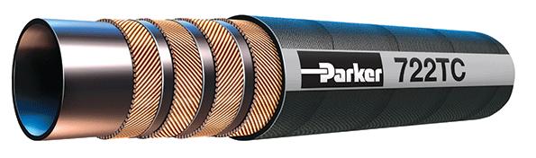
92 Hoses
93
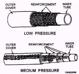
94 Construction of Hoses It is divided into three layers: a) Inner tube b) reinforcement c) outer covering a) Inner tube :This is the passage through which the oil would be flowing.it is made of a suitable hoses material.selection of ID of this tube is done as in case of pipes. b) Reinforcement: The inner tube is covered with reinforcement material to provide sufficient strength to it. It is made up of fiber or steel wire braiding. Depending on pressure,two or three layers may be given.
95 c) Outer covering : To avoid reinforcement from getting damaged by the impact or sharp objects outer protective cover is given. It also covers reinforcement form abrasion,corrosion nad other damages.
CH.4 Basic Components of Hydraulic and Pneumatic System/16 M HAP/17522/AE5G
 Content : 4.1 Hydraulic and Pneumatic actuators. 10 Marks Hydraulic Actuators - Hydraulic cylinders (single, double acting and telescopic) construction and working, Hydraulic motors (gear and piston type)
Module 5: Valves. CDX Diesel Hydraulics. Terms and Definitions. Categories of Valves. Types of Pressure Control Valves
 Terms and Definitions Categories of Valves Types of Pressure Control Valves Types and Operation of Pressure Relief Valves Operation of an Unloading Valve Operation of a Sequencing Valve Operation of a
Test Which component has the highest Energy Density? A. Accumulator. B. Battery. C. Capacitor. D. Spring.
 Test 1 1. Which statement is True? A. Pneumatic systems are more suitable than hydraulic systems to drive powerful machines. B. Mechanical systems transfer energy for longer distances than hydraulic systems.
LogSplitterPlans.Com
 Hydraulic Pump Basics LogSplitterPlans.Com Hydraulic Pump Purpose : Provide the Flow needed to transmit power from a prime mover to a hydraulic actuator. Hydraulic Pump Basics Types of Hydraulic Pumps
INTRODUCTION: Rotary pumps are positive displacement pumps. The rate of flow (discharge) of rotary pump remains constant irrespective of the
 of rotary pump remains constant irrespective of the") INTRODUCTION: Rotary pumps are positive displacement pumps. The rate of flow (discharge) of rotary pump remains constant irrespective of the pressure. That is, even at very high pressure, these pumps can
INTRODUCTION: Rotary pumps are positive displacement pumps. The rate of flow (discharge) of rotary pump remains constant irrespective of the pressure. That is, even at very high pressure, these pumps can
Pneumatic & Hydraulic SYSTEMS
 Pneumatic & Hydraulic SYSTEMS CHAPTER EIGHT HYDRAULIC PUMPS AND ACTUATORS Dr. Ibrahim Naimi The higher the discharge pressure, the lower the volumetric efficiency because internal leakage
LESSON 2 BASIC CONSTRUCTION AND OPERATION OF HYDRAULIC ACTUATING DEVICES, FLOW CONTROL, AND DIRECTIONAL DEVICES. STP Tasks:
 LESSON 2 BASIC CONSTRUCTION AND OPERATION OF HYDRAULIC ACTUATING DEVICES, FLOW CONTROL, AND DIRECTIONAL DEVICES STP Tasks: 552-758-1003 552-758-1071 OVERVIEW LESSON DESCRIPTION: In this lesson you will
Marine Engineering Exam Resource Review of Hydraulics
 1. What is Pascal s law? Pressure confined on a confined fluid will transmit the pressure in all directions and act with equal force on all areas at right angles. 2. How does the law pertain to hydraulics?
speed hydraulic motors. Permission granted to reproduce for educational use only. Contrast the operation of fixed- and variable-
 Chapter 9 Actuators Workhorses of the System 1 Objectives Describe the construction and operation of basic hydraulic cylinders, limited-rotation actuators, and motors. Compare the design and operation
Hydraulic Pumps Classification of Pumps
 Fluidsys Training Centre, Bangalore offers an extensive range of skill-based and industry-relevant courses in the field of Pneumatics and Hydraulics. For more details, please visit the website: https://fluidsys.org
Topic 1. Basics of Oil Hydraulic Systems
 Topic 1. Basics of Oil Hydraulic Systems Fluid power Fluid power is the technology that deals with the generation, control and transmission of forces and movement of mechanical element or system with the
Describe the function of a hydraulic power unit
 Chapter 7 Source of Hydraulic Power Power Units and Pumps 1 Objectives Describe the function of a hydraulic power unit and identify its primary components. Explain the purpose of a pump in a hydraulic
Hydrostatic Drive. 1. Main Pump. Hydrostatic Drive
 Hydrostatic Drive The Hydrostatic drive is used to drive a hydraulic motor at variable speed. A bi-directional, variable displacement pump controls the direction and speed of the hydraulic motor. This
Lecture 6. This week: Lab 13: Hydraulic Power Steering [ Lab 14: Integrated Lab (Hydraulic test bench) ]
![Lecture 6. This week: Lab 13: Hydraulic Power Steering [ Lab 14: Integrated Lab (Hydraulic test bench) ]](/thumbs/84/91055223.jpg "Lecture 6. This week: Lab 13: Hydraulic Power Steering [ Lab 14: Integrated Lab (Hydraulic test bench) ]") 133 Lecture 6 This week: Lab 13: Hydraulic Power Steering [ Lab 14: Integrated Lab (Hydraulic test bench) ] 4-way directional control valve; proportional valve; servo-valve Modeling / Analysis of a servo-valve
133 Lecture 6 This week: Lab 13: Hydraulic Power Steering [ Lab 14: Integrated Lab (Hydraulic test bench) ] 4-way directional control valve; proportional valve; servo-valve Modeling / Analysis of a servo-valve
Design and Fabrication of Sequencing Circuit with Single Double Acting Cylinder
 Design and Fabrication of Sequencing Circuit with Single Double Acting Cylinder V.G.Vijaya Department of Mechatronics Engineering, Bharath University, Chennai 600073, India ABSTRACT: This project deals
Definitions of Technical Terms
 Definitions of Technical Terms ABSOLUTE A measure having as it s zero point of base the complete absence of the entity being measured. ABSOLUTE PRESSURE A pressure scale with zero point at a perfect vacuum.
ESCONDIDO FIRE DEPT TRAINING MANUAL Section DRIVER OPERATOR Page 1 of 13 Pumps and Accessory Equipment Revised
 DRIVER OPERATOR Page 1 of 13 PUMPS AND ACCESSORY EQUIPMENT Pumps are designed for many different purposes. In order to understand the proper application and operation of a pump in a given situation, firefighters
WINTER 14 EXAMINATION Subject Code: Model Answer Page No: 1/20
 Subject Code: 17522 Model Answer Page No: 1/20 Important Instructions to examiners: 1) The answers should be examined by key words and not as word-to-word as given in the model answer scheme. 2) The model
CHAPTER 11 BASIC ACTUATING SYSTEMS
 INTRODUCTION CHAPTER 11 BASIC ACTUATING SYSTEMS The actuating systems consist of the hydraulic components used to direct and control the flow of pressurized fluid as well as the components used to perform
2. Power Steering System
 2. Power Steering System A: HYDRAULIC SYSTEM POWER STEERING SYSTEM The fluid pump is directly driven by the engine through a belt. The fluid flow is maintained almost constant regardless of change in the
Check Valves Check Valves are the simplest form of directional control valves, but they can also be used as pressure controls.
 Check Valves Check Valves are the simplest form of directional control valves, but they can also be used as pressure controls. Standard Check Valve The standard check valve permits free flow in one direction
three different ways, so it is important to be aware of how flow is to be specified
 Flow-control valves Flow-control valves include simple s to sophisticated closed-loop electrohydraulic valves that automatically adjust to variations in pressure and temperature. The purpose of flow control
SERIES Waterman* DESCRIPTION FLOW PRESSURE PAGE NO.
 Contents SERIES Waterman* DESCRIPTION FLOW PRESSURE PAGE NO. NVH081...12CNVH1...Needle Valve...10 GPM... 5500 PSI... FC5-FC6 NVH101...15CNVH1...Needle Valve...16 GPM... 5500 PSI... FC7-FC8 NV162...21CNV2...Needle
I) Clamping the work piece II) Drilling the work piece. III) Unclamping the work piece. 10
 Clamping the work piece II) Drilling the work piece. III) Unclamping the work piece. 10") Seventh Semester B.E. III IA Test, 2014 USN 1 P E M E PES INSTITUTE OF TECHNOLOGY (Bangalore South Campus) (Hosur Road, 1KM before Electronic City, Bangalore-560 100) Department of Mechanical Engineering
Seventh Semester B.E. III IA Test, 2014 USN 1 P E M E PES INSTITUTE OF TECHNOLOGY (Bangalore South Campus) (Hosur Road, 1KM before Electronic City, Bangalore-560 100) Department of Mechanical Engineering
Super Charged Piston Pumps Variable Displacement For Open Circuits. PAVC Medium Pressure
 aerospace climate control electromechanical filtration fluid & gas handling hydraulics pneumatics process control sealing & shielding PAVC Medium Pressure Super Charged Piston Pumps Variable Displacement
Notes on Hydraulic Systems
 Notes on Hydraulic Systems Dr. P A Sastry Professor, Dept. of Mechanical Engg. MVSR Engineering College, Hyderabad. The accompanying material on Hydraulic Systems (HS) is intended to cover the syllabus
2. Power Steering System
 W1860BE.book Page 5 Tuesday, January 28, 2003 11:01 PM 2. Power Steering System A: HYDRAULIC SYSTEM The fluid pump is directly driven by the engine through a belt. The fluid flow is maintained almost constant
Lecture 6. Systems review exercise To be posted this weekend Due next Friday (3/6)
") 150 Systems review exercise To be posted this weekend Due next Friday (3/6) Lecture 6 Coming week: Lab 13: Hydraulic Power Steering Lab 14: Integrated Lab (Hydraulic test bench) Topics today: Pumps and
150 Systems review exercise To be posted this weekend Due next Friday (3/6) Lecture 6 Coming week: Lab 13: Hydraulic Power Steering Lab 14: Integrated Lab (Hydraulic test bench) Topics today: Pumps and
FRL unit consist of Filterations, Regulators and Lubricator unit.
 4.1 AIR CONTROL 4.1.1 Fluid Conditioner FRL unit consist of Filterations, Regulators and Lubricator unit. It is also known as Air Service Unit. Primary function is to provide clean air at optimal pressure
Series PAVC Variable Volume, Piston Pumps
 Series PVC Variable Volume, Piston Pumps Catalog 26-11-1/US 95 Introduction Series PVC Quick Reference Data Chart Pump Model Displacement CM 3 /REV (IN 3 /REV) Pump Delivery *pprox. Noise Levels db() Input
Introduction. General Information. Systems Operation
 Systems Operation Introduction Reference: For illustrated Specifications, refer to the Specifications For 416, 426, 428, 436, 438, & Series II Backhoe Loaders Transmission, Form No. SENR3131. If the specifications
LECTURE 15 TO 17 DIRECTIONAL CONTROL VALVES FREQUENTLY ASKED QUESTIONS
 LECURE 15 O 17 DIRECIONL CONROL VLVES FREQUENLY SKED QUESIONS 1. Explain briefly the function of directional control valves o o start, stop, accelerate, decelerate and change the direction of motion of
Super Charged Piston Pumps Variable Displacement For Open Circuits. PAVC Medium Pressure
 aerospace climate control electromechanical filtration fluid & gas handling hydraulics pneumatics process control sealing & shielding PAVC Medium Pressure Super Charged Piston Pumps Variable Displacement
INDIAN INSTITUTE OF TECHNOLOGY KHARAGPUR NPTEL ONLINE CERTIFICATION COURSE. On Industrial Automation and Control
 INDIAN INSTITUTE OF TECHNOLOGY KHARAGPUR NPTEL ONLINE CERTIFICATION COURSE On Industrial Automation and Control By Prof. S. Mukhopadhyay Department of Electrical Engineering IIT Kharagpur Topic Lecture
CH.6 Hydraulic and Pneumatic Circuits/20M. 6.1 Hydraulic Circuits
 Content : 6.1 Hydraulic Circuits 10 Marks Hydraulic symbols Meter in, Meter out. Bleed off, Sequencing. Introduction to electro-hydraulics concept, principles and applications Applications of hydraulic
Nomenclature... xi Hydraulic Laws, Theorems, and Equations...xii
 Nomenclature... xi Hydraulic Laws, Theorems, and Equations...xii 1 Introduction 1.1 Component Design Perspective...1 1.2 Hydraulic Power Evolution...2 1.3 Hydraulic Applications...6 1.4 Component Design
SUBJECT: PUMP TYPES & OPERATIONS
 SUBJECT: PUMP TYPES & OPERATIONS ABOUT THE SESSION This session will highlight different types of pumps and its working. INTRODUCTION In Hydraulic system, the pump converts mechanical energy (hydraulic
Section 6.1. Implement Circuit - General System. General: TF Configuration TB Configurations Implement Control Valve:
 Section 6.1 Implement Circuit - General System General: TF Configuration... 6.1.3 TB Configurations... 6.1.5 Implement Pump Breakdown... 6.1.6 Operational Description: General... 6.1.7 Compensator Control...
Lesson 5: Directional Control Valves
 : Directional Control Valves Basic Hydraulic Systems Hydraulic Fluids Hydraulic Tank Hydraulic Pumps and Motors Pressure Control Valves Directional Control Valves Flow Control Valves Cylinders : Directional
Flow direction is reversed by tilting the swash plate to the opposite side of the neutral or zero displacement position.
 General Description Axial piston variable displacement pumps, Series 20, are of swash plates construction with variable flow capability suitable for hydrostatic transmission with closed loop circuit. The
Input, Control and Processing elements
 PNEUMATIC & HYDRAULIC SYSTEMS CHAPTER FIVE Input, Control and Processing elements Dr. Ibrahim Naimi Valves The function of valves is to control the fluid path or the pressure or the flow rate. Depending
COOPERATIVE PATENT CLASSIFICATION
 CPC F COOPERATIVE PATENT CLASSIFICATION MECHANICAL ENGINEERING; LIGHTING; HEATING; WEAPONS; BLASTING (NOTE omitted) ENGINES OR PUMPS F01 MACHINES OR ENGINES IN GENERAL (combustion engines F02; machines
Hydraulic energy control, conductive part
 Chapter 2 2 Hydraulic energy control, conductive part Chapter 2 Hydraulic energy control, conductive part To get the hydraulic energy generated by the hydraulic pump to the actuator, cylinder or hydraulic
POWER ASSISTED SYSTEM (POWER STEERING)
") POWER ASSISTED SYSTEM (POWER STEERING) TILT STEERING COLUMN 1. Tilt Steering Column A: TILT MECHANISM The steering wheel vertical position can be adjusted within a 38 mm (1.50 in) range by using the tilt
POWER ASSISTED SYSTEM (POWER STEERING) TILT STEERING COLUMN 1. Tilt Steering Column A: TILT MECHANISM The steering wheel vertical position can be adjusted within a 38 mm (1.50 in) range by using the tilt
FLUID POWER FLUID POWER EQUIPMENT TUTORIAL HYDRAULIC AND PNEUMATIC MOTORS. This work covers part of outcome 2 of the Edexcel standard module:
 FLUID POWER FLUID POWER EQUIPMENT TUTORIAL HYDRAULIC AND PNEUMATIC MOTORS This work covers part of outcome 2 of the Edexcel standard module: UNIT 21746P APPLIED PNEUMATICS AND HYDRAULICS The material needed
Contents. Quality Hydraulic Components from the Webtec Range. Introduction. Hydraulic Flow Control Valves
 Quality Hydraulic Components from the Webtec Range Contents Description Section Webtec Products Ltd Introduction 1 Hydraulic Flow Control Valves 2 Hydraulic Directional Control Valves and Check Valves
Module 4: Actuators. CDX Diesel Hydraulics. Terms and Definitions. Cylinder Actuators
 Terms and Definitions Cylinder Actuators Symbols for Actuators Terms and Definitions II Cylinders Providing Linear Motion Cylinders Providing Angular Motion Parts of Actuators Mounting of Actuators Seals
TRANSLATION (OR LINEAR)
") 5) Load Bearing Mechanisms Load bearing mechanisms are the structural backbone of any linear / rotary motion system, and are a critical consideration. This section will introduce most of the more common
5) Load Bearing Mechanisms Load bearing mechanisms are the structural backbone of any linear / rotary motion system, and are a critical consideration. This section will introduce most of the more common
DESCRIPTION & OPERATION
 DESCRIPTION & OPERATION BRAKE BOOSTER Delco-Moraine Single Diaphragm A combined vacuum-hydraulic unit which uses a combination of intake manifold vacuum and atmospheric pressure to provide power assist.
CENTAC Inlet and Bypass Valve Positioners
 CENTAC Inlet and Bypass Valve Positioners INGERSOLL-RAND AIR COMPRESSORS INLET AND BYPASS VALVE POSITIONERS Copyright Notice Copyright 1992, 1999 Ingersoll-Rand Company THIS CONTENTS OF THIS MANUAL ARE
Full Range Pressure Compensating Variable Flow Control
 Engineering & Manufacturing Solutions Specifications: See flow chart for capacity. Rated for 3000 psi (207 bar). Weighs 7- ¾ lbs. (3.52 kg). 30-Micron Filtration Recommended. Torque to turn side lever
Fluidics. Hydraulic circuit. Course teacher Prof. Mahbubur Razzaque
 COURSE NUMBER: ME 433 Fluidics Hydraulic circuit Course teacher Prof. Mahbubur Razzaque 1 FAIL-SAFE CIRCUITS Fail-safe circuits are those designed to prevent injury to the operator or damage to equipment.
Rotary Internal Combustion Engine: Inventor: Gary Allen Schwartz
 Rotary Internal Combustion Engine: Inventor: Gary Allen Schwartz 1 The following is a design for a circular engine that can run on multiple fuels. It is much more efficient than traditional reciprocating
VB VALVES & AUTOMATION
 Introduction to Valve What are Valves? Valves are mechanical device that controls the flow and pressure within a system or process. They are essential components of a piping system that conveys liquids,
MODULE- 5 : INTRODUCTION TO HYDROSTATIC UNITS (PUMPS AND MOTORS)
") MODULE- 5 : INTRODUCTION TO HYDROSTATIC UNITS (PUMPS AND MOTORS) LECTURE- 18 : BASIC FEATURES OF SOME Hydraulic Pumps & Motors Introduction In this section we shall discuss the working principles and fundamental
MODULE- 5 : INTRODUCTION TO HYDROSTATIC UNITS (PUMPS AND MOTORS) LECTURE- 18 : BASIC FEATURES OF SOME Hydraulic Pumps & Motors Introduction In this section we shall discuss the working principles and fundamental
GPM Hydraulic Consulting, Inc. P.O. Box 689. Social Circle, GA Hydraulic Consulting, Inc
 Hydraulic Consulting, Inc This special promotional CD is to demonstrate how your hydraulic troubleshooting manual can be ordered as an Adobe Acrobat ebook. It can be installed on any computer with the
LECTURE 24 TO 26 - HYDRAULIC CIRCUIT DESIGN FREQUENTLY ASKED QUESTIONS
 LECUE 24 O 26 - HYDAULIC CICUI DESIGN EQUENLY ASKED QUESIONS 1. List three important considerations to be taken into account while designing a hydraulic circuit here are 3 important considerations in designing
FLUID POWER TUTORIAL HYDRAULIC PUMPS APPLIED PNEUMATICS AND HYDRAULICS H1
 FLUID POWER TUTORIAL HYDRAULIC PUMPS This work covers outcome 2 of the Edexcel standard module: APPLIED PNEUMATICS AND HYDRAULICS H1 The material needed for outcome 2 is very extensive so the tutorial
Lecture 6. Systems review exercise To be posted this afternoon Due in class (10/23/15)
") 153 Systems review exercise To be posted this afternoon Due in class (10/23/15) Lecture 6 Coming week: Lab 13: Hydraulic Power Steering Lab 14: Integrated Lab (Hydraulic test bench) Topics today: 2 min
153 Systems review exercise To be posted this afternoon Due in class (10/23/15) Lecture 6 Coming week: Lab 13: Hydraulic Power Steering Lab 14: Integrated Lab (Hydraulic test bench) Topics today: 2 min
Instructor Training Manual. Chapter 6 HYDRAULICS & PNEUMATICS
 Instructor Training Manual Chapter 6 HYDRAULICS & PNEUMATICS Learning Objectives 1. The purpose of this chapter is to provide a basic introduction to the principles of hydraulics & pneumatics and their
Chapter 13: Application of Proportional Flow Control
 Chapter 13: Application of Proportional Flow Control Objectives The objectives for this chapter are as follows: Review the benefits of compensation. Learn about the cost to add compensation to a hydraulic
Chapter Thirteen. Nose Wheel Steering Systems. A. Small Aircraft. B. Large Aircraft. C. Shimmy Dampers
 Chapter Thirteen Nose Wheel Steering Systems A. Small Aircraft Almost all airplanes with tricycle landing gear have some provisions for steering on the ground by controlling the nose wheel. Some of the
Catalog HY /US Flow Control Valves SERIES CAVITY DESCRIPTION FLOW PRESSURE LPM/GPM BAR/PSI
 Contents SERIES CAVITY DESCRIPTION FLOW PRESSURE LPM/GPM BAR/PSI NEED VALVES J02A2... C08-2... Needle Valve, Cartridge Type...45/12... 420/6000... NVH081... C08-2... Needle Valve, Cartridge Type...38/10...
Syslog Technologies Innovative Thoughts
 AUTOMATIC PNEUMATIC WATER PUMPING SYSTEM SYNOPSIS The aim of the project is pneumatic operated water pumping system. Radial plunger Pneumatic Water pumping system are reciprocating pump in which the piston
Fisher 657 Diaphragm Actuator Sizes and 87
 Instruction Manual 657 Actuator (30-70 and 87) Fisher 657 Diaphragm Actuator Sizes 30 70 and 87 Contents Introduction... 1 Scope of Manual... 1 Description... 2 Specifications... 2 Installation... 3 Mounting
Section 6.1. Implement Circuit - General System. General: TF Configuration TB Configurations Implement Control Valve:
 Section 6.1 Implement Circuit - General System General: TF Configuration... 6.1.3 TB Configurations... 6.1.5 Implement Pump Breakdown... 6.1.6 Operational Description: General... 6.1.7 Compensator Control...
Catalog HY /NA. Catalog HY /NA. Parker Hannifin Corporation Hydraulic Pump Division Marysville, Ohio USA
 Catalog HY28-6/NA PV, PVT Series Piston Pumps Variable Volume Catalog HY28-6/NA 1 Catalog HY28-6/NA Notes Series PV 2 Catalog HY28-6/NA Introduction Series PV Quick Reference Data Chart Pump Delivery Approx.
Content. Chapter 1 Hydraulic energy converters... 10
 Content Chapter 1 Hydraulic energy converters... 10 1.1 List of symbols... 13 1.2 Hydraulic pump types, constant output... 14 1.2.1 External gear pumps... 16 1.2.2 Internal gear pumps... 17 1.2.3 Vane
Series 20 Axial Piston Pumps. Technical Information
 Series 20 Axial Piston Pumps Technical Information General Description INTRODUCTION Sauer-Danfoss a world leader in hydraulic power systems has developed a family of axial piston pumps. DESCRIPTION Sauer-Danfoss
Internal Pressure Pipe Cutters. Manual E540
 Internal Pressure Pipe Cutters Manual E540 Contents Logan Internal Pressure Pipe Cutters Overview...2 Uses...2 Construction...2 Tool Illustration...3 Operation...2 Single Cut from a Fixed Platform... 2
Module 13: Mechanical Fuel Injection Diagnosis and Repair
 Terms and Definitions Parts of Injection Nozzles Types of Nozzle Valves Operation of an Injection Nozzle Fuel Flow Through the Unit Injector Optional Features on Fuel Injection Pumps Main Parts of a Distributor-Type
Series 20 Axial Piston Pumps. Technical Information
 Series 20 Axial Piston Pumps Technical Information General Description INTRODUCTION Sauer-Danfoss a world leader in hydraulic power systems has developed a family of axial piston pumps. DESCRIPTION Sauer-Danfoss
Aircraft Maintenance Prof. A.K Ghosh Prof. Vipul Mathur Department of Aerospace Engineering Indian Institute of Technology, Kanpur
 Aircraft Maintenance Prof. A.K Ghosh Prof. Vipul Mathur Department of Aerospace Engineering Indian Institute of Technology, Kanpur Lecture 05 Aircraft Landing Gear System Now, coming to the next aircraft
RELEASING PRESSURE IN THE HYDRAULIC SYSTEM,
 Testing And Adjusting Introduction NOTE: For Specifications with illustrations, make reference to SPECIFICATIONS for 225 EXCAVATOR HYDRAULIC SYSTEM, Form No. SENR7734. If the Specifications are not the
LECTURE-23: Basic concept of Hydro-Static Transmission (HST) Systems
 Systems") MODULE-6 : HYDROSTATIC TRANSMISSION SYSTEMS LECTURE-23: Basic concept of Hydro-Static Transmission (HST) Systems 1. INTRODUCTION The need for large power transmissions in tight space and their control
MODULE-6 : HYDROSTATIC TRANSMISSION SYSTEMS LECTURE-23: Basic concept of Hydro-Static Transmission (HST) Systems 1. INTRODUCTION The need for large power transmissions in tight space and their control
Attention is drawn to the following places, which may be of interest for search:
 F01B MACHINES OR ENGINES, IN GENERAL OR OF POSITIVE-DISPLACEMENT TYPE, e.g. STEAM ENGINES (of rotary-piston or oscillating-piston type F01C; of non-positive-displacement type F01D; internal-combustion
TWO-STAGE HYDRAULIC PUMP. RWP55-IBT-Air
 ORIGINAL INSTRUCTIONS Form No.1000458 5 SPX Corporation 5885 11th Street Rockford, IL 61109-3699 USA Tech. Services: (800) 477-8326 Fax: (800) 765-8326 Order Entry: (800) 541-1418 Fax: (800) 288-7031 Internet
Service and Parts Manual. Minimum Filtration Required:
 R GRESEN Hydraulics Model V0 Sectional Body Directional Control Valve Service and Parts Manual Maximum Operating Pressure: Minimum Filtration Required: 00 PSI ( bar) 0 Micron The information in this Service
Chapter B-3. Chapter 3. Actuators and output devices. Festo Didactic TP101
 155 Chapter 3 Actuators and output devices Festo Didactic TP101 156 An actuator is an output device for the conversion of supply energy into useful work. The output signal is controlled by the control
AUXILIARY COMPONENTS
 CHAPTER 9 AUXILIARY COMPONENTS Fluid Power Circuits and Controls, John S.Cundiff, 2001 INTRODUCTION Discussion of the hardware needed to connect the various components (pumps, actuators, valves, accumulators,
Experiments on Hydraulic and Pneumatic circuit trainers HYDRAULIC CIRCUITS:
 Experiments on Hydraulic and Pneumatic circuit trainers HYDRAULIC CIRCUITS: Hydraulic circuits are used in high power and high load applications such as earth moving equipment. The pressure used in industrial
Torque Converter, Transmission Pump, Screen And Filter
 Page 13 of 27 Transmission Hydraulic System In Forward (Engine Running - Type 2 & 3 Control Valve Shown) (4) Transmission control valve. (5) Neutralizer valve. (6) Neutralizer solenoid. (7) Flow control
t2_ il PioC Oper. led Relet Valve Symbol ~~~ CHAPTER 12 Pilot Operated Pressure Control Valves
 CHAPTER 12 Pilot Operated Pressure Control Valves Unlike a simple or direct operated pressure control valve, where a spool is held biased by spring pressure only, a pilot operated valve has its spool biased
Pneumatic Control System
 Matakuliah: Teknik Otomasi Pneumatic Control System Eka Maulana, ST, MT, MEng. What is Pneumatic? Pneumatics is a type of power transmission that uses a gas ( in our case, air) and pressure differential
Hydrostatic Power Train
 Chapter Hydrostatic Power Train Specifications................................................................. -3 Test Specifications........................................................ -3 Repair
Instructions for Installation, Operation, Care and Maintenance
 Bulletin 59 Model DDX Deluge Valve (50 mm), ½ (65 mm), (80 mm), 76 mm, 4 (00 mm), 6 (50 mm), 65 mm & 8 (00 mm) Bulletin 59 Instructions for Installation, Operation, Care and Maintenance Wet Pilot Line,
Infinitely Variable Capacity Control
 Purdue University Purdue e-pubs International Compressor Engineering Conference School of Mechanical Engineering 1972 Infinitely Variable Capacity Control K. H. White Ingersoll-Rand Company Follow this
DENISON HYDRAULICS open loop pump controls series P140 A-mod, P260 B-mod service information
 DENISON HYDRAULICS open loop pump controls series P10 A-mod, P260 B-mod service information Publ. S1-AM02-A replaces S1-AM02 01-97 CONTENTS typical characteristics-------------------------------------------------------------------------------
Glossary. Visit Us Online: ABSOLUTE A measure having as its zero point or base the complete absence of the entity being measured.
 ABSOLUTE A measure having as its zero point or base the complete absence of the entity being measured. ABSOLUTE PRESSURE (psia) The pressure above absolute zero, the sum of atmospheric and gauge pressure.
Control Valves Positioner
 Control Valves Positioner HiFlo Valve Positioner Easy calibration Corrosion-resistant cover and base Withstands 150 psi at all parts Two -sided cam for easy field reversibility Optional / NPT for piped
Control Valves Positioner
 Control Valves Positioner HiFlo HiFlo Valve Positioner Corrosion-resistant cover and base Easy calibration Withstands 150 psi at all parts Two -sided cam for easy field reversibility Optional / NPT for
Logic elements. Differential pressure sensing elements for applications up to 350 bar (5000 psi) and 400 L/min (100 USgpm)
 and 400 L/min (100 USgpm)") Hydraulic Screw-in Cartridge Valves (SiCV) Logic elements Differential pressure sensing elements for applications up to 50 bar (5000 psi) and 400 L/min (00 USgpm) Logic elements LOGC ELEMENTS... -4 APPLCATON
Hydraulic Screw-in Cartridge Valves (SiCV) Logic elements Differential pressure sensing elements for applications up to 50 bar (5000 psi) and 400 L/min (00 USgpm) Logic elements LOGC ELEMENTS... -4 APPLCATON
Basic Instruments Introduction Classification of instruments Operating principles Essential features of measuring
 Basic Instruments www.worldwebsites8.blogspot.com Introduction Classification of instruments Operating principles Essential features of measuring instruments PMMC Instruments Moving Iron instruments Introduction
Series PVP Variable Volume Piston Pumps
 Series PVP Variable Volume Piston Pumps Catalog HY28-2661-CD/US zp2 hpm12-1.p65, lw, jk 1 Notes Series PVP hpm12-1.p65, lw, jk 2 Introduction Series PVP Series Sizes 6-14 Phased Out For Reference Only
Type 657 Diaphragm Actuator Sizes and 87
 Instruction Manual Form 1900 January 2000 Type 657-70 & 87 Type 657 Diaphragm Actuator Sizes 30-70 and 87 Contents Introduction............................... 1 Scope of Manual.............................
Pilot Oil Supply Circuit
 Pilot Oil Supply Circuit Introduction Pilot system oil output from pilot pump (42) has the following three main functions: 1. To control main pump output. 2. To provide easier operation of control levers.
 www.iranfluidpower.com آموزش هیدرولیک N A T I O N A L F L U I D P O W E R A S S O C I A T I O N FLUID POWER TRAINING Basic Hydraulics Course Introduction NFPA is pleased to present the Basic Hydraulics
Hydraulic Pump Series VP1 Variable Displacement
 Variable Displacement Catalog 9129 8222-02 February 1999, GB Content Page General information 3 Design 3 Specifications 4 Ordering information 4 VP1 cross section 4 Installation dimensions 5 Line dimensioning
Pumps. Pumps GoTo Europe
 Pumps GoTo Europe 7 Pumps Axial piston pumps Axial piston pumps in swash plate and bent axis design are intended for the medium and high pressure range. Variations in the designs, in the performance ranges
Section 35 Chapter 2 HYDRAULIC SYSTEM HOW IT WORKS AND TROUBLESHOOTING NH
 Section 35 Chapter HYDRAULIC SYSTEM HOW IT WORKS AND TROUBLESHOOTING 6-80NH TABLE OF CONTENTS GENERAL INTRODUCTION... 35-3 Hydraulic Pumps... 35-3 Standard Flow PFC Pump Layout... 35-5 MegaFlow PFC Pump