FRL unit consist of Filterations, Regulators and Lubricator unit.
|
|
|
- Brandon Jordan
- 5 years ago
- Views:
Transcription
1

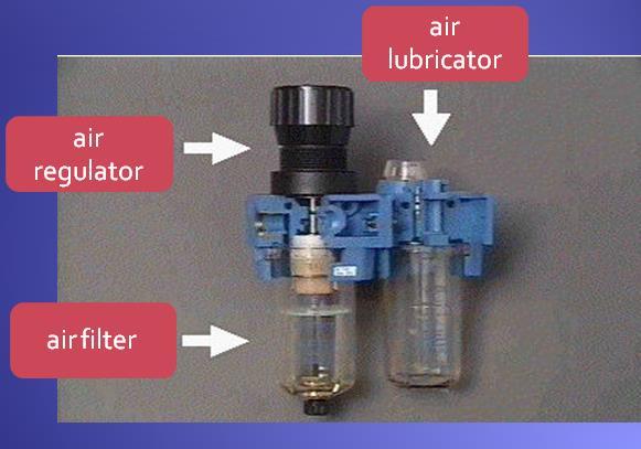
2 4.1 AIR CONTROL Fluid Conditioner FRL unit consist of Filterations, Regulators and Lubricator unit. It is also known as Air Service Unit. Primary function is to provide clean air at optimal pressure and occasionally adds lubrication to extent the life of the pneumatic system components which need lubrication. Figure 4.4 : FRL Unit
3


4 Air Filter Filters all dust, rust, and condensed moisture in the compressed air. All dust, moisture are trapped in a storage underneath and must be emptied regularly
 air pressure in the")
5 Regulator To ensure a steady (stable) air pressure in the system
6 Lubricator Supplies a mist of lubrication oil to the system in a controlled manner. The oil is used for lubrication of mechanical component Lubrication is need; a) the actuator is working under continuous reciprocating operation b) using large pneumatic cylinder
7 Air Service Unit Also known as FRL unit and symbol with lubrication without lubrication
8 4.1.2 Air Control Valve a) Directional Control Valve (DCV) A valve is a device which receives an external command. The command can either be in the form of mechanical, fluid pilot signal or electrical. This command is used either to release, stop or redirect the fluid that flows through it.
9 A control mechanism is needed to control air flow direction, in and out the cylinder for its operation. It is known as directional control valve (DCV)
10 Basic Valve Symbols Valve symbols is build from the following basic symbols; position Number of switching position Air flow lines, the arrow show air flow direction Shut off position
11 Ports and Positions for Control valve

12 Directional Control Valve Symbols
13 Valve Actuation Valve need some kind of mechanism to switch one position to another. Among the actuation mechanism are as follows;

14 Type of Actuation Symbols

15 Manual Actuated Mechanical Actuated
16 Pressure Actuated Solenoid Actuated
17 Example 1: 3/2 Way Valve There is a standard way to marking each port of the valve ( according ISO 11727) 1- compressed air supply 2- connection to cylinder 3- exhaust port The control valve usually drawn at its normal position ( before operation)
18 Example 2: 5/3 Way Valve 1- compressed air supply 2 & 4 - connection to cylinder 3 & 5- exhaust port The control valve usually drawn at its normal position ( before operation)
19

20 Pressure Actuated Solenoid Actuated Solenoid valves convert electrical energy into pneumatic energy. It can also used DC or AC supply. The advantages to used solenoid valve is that, electrical signal are very fast and efficient in actuating movement.


21 DCV Design There are two types of construction that is spool/sleeve/slide and popet. Recently spool valve is the most frequently used. Spool Valve Spool valve may be built for more than two switching position with normally spring centered. The valve is also balanced and uses only small actuating forces. Spool valve may operate without elastomer seals because the tolerance is very small. Figure 4.10 Spool Valve

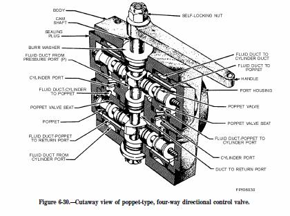
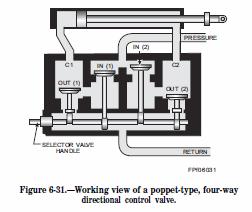
22 Popet Valve Although spool valve is favourable in modern design, popet valve also offer significant advantage. Popet valve do not required lubrication and no close tolerance gaps on moving parts since they provide head-on instead of dynamic sealing. Popet valve also requires much higher operating force.
23
24 b) Pressure Control Valve The function of pressure control valve is to influence the pressure of the compressed air or react to specific values of pressure. The most commonly term used for pressure reducing valve is pressure regulator. Pressure reducing valve is used to maintain a nearly constant secondary pressure (adjusted pressure) and independent of pressure fluctuation on the primary side.
25 Pressure Reducing Valve

26 c) Ancillary Valves i) Check valves The function of check valve is allow airflow from one direction only. The opposite airflow will be cut off. It will also prevent backflow in diverse applications. To control this, check valve is equipped with or without spring with popet.


27 ii) Shuttle Valve Shuttle valve is also known as OR valve where it will only allow flow in only one direction at a time. The flow is cut off by sealing body that are made in the form of ball, cone or disc seal.


28 iii) AND Valve Double Cut-Off Valve normally is called as AND valve. Means that both inpu must be pressurized to obtain an output signal.
 to the actuator to which it is attached (Port A).")
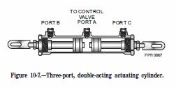
29 iv) Quick Exhaust Valve Quick exhaust valve is used as a speed controlling device. It allow the air to flow from the power port (Port P) to the actuator to which it is attached (Port A). When the actuator is exhausting, the valve element is shuttle to the left where it blocks port P and the exhaust air can rapidly flow through a large exhaust port (R) to atmosphere.
30 4.2 ACTUATOR (PNEUMATIC DRIVE ) Pneumatic drives convert the energy of pressure into mechanical work (pressure and flow into force and velocity). The work done by pneumatic actuators can be linear or rotary Linear movement is obtained by piston cylinder. Reciprocating rotary motion with an angle up to 270 O can be obtained by vane or rack and pinion type actuation. Pneumatic drive is devided into four category such as:- Linear Cylinder Rotary Cylinder Special Cylinder Compressed Air Motors However, it is necessary to have knowledge of basic construction on pneumatic cylinder when dealing with it. Figure 4.18 illustrates the main component of pneumatic cylinder.

31 Main Component of Double Acting Cylinder

32 Common Mounting for Pneumatic Cylinder
 and Double Acting Cylinder (Figure 4.")

33 a) LINEAR CYLINDER Linear cylinder is is a very common cylinder used in pneumatic system. T wo types of linear cylinder is Single Acting Cylinder (Figure 4.18) and Double Acting Cylinder (Figure 4.19) Single acting cylinder is used whenever the force is needed in one direction only and where the return stroke is unimpeded and unloaded. Double acting cylinder is used whenever linear motion with small and medium forces is required and work is to be performed in both directions. Single Acting Cylinder-Spring Retract Type Double Acting Cylinder

34 b) ROTARY CYLINDER Rotary cylinder is used to transform the linear motion of a double acting cylinder into rotary motion. The angle of the rotation is also limited. Standard angle of rotation is commonly 90 O or 180 O. Figure 4.20 illustrates Rotary Actuators. Rotary Actuators
35 c) SPECIAL CYLINDER Double Acting Cylinder with Double Piston Rod This cylinder can perform work at both sides. The guidance of the piston is improved by the used of bearing.

36 Rodless cylinders Rodless Cylinder with Mechanical Connections Rodless Cylinder with Magnetic Force Rodless cylinders differ from basic air cylinders in that no piston rod extends outside the cylinder body. Instead, the internal piston is connected to an external carriage, by means of a magnetic or mechanical coupling system.


37 Multi Position Cylinder Multiposition Cylinder is used to attained number of stable position where two or more cylinder are combine. Normally it is used for sorting operations, movement of flaps.


38 Telescopic cylinder Telescopic cylinder is design for long strokes. It can also holds large forces and consists of several nested cylinder.


39 Tandem Cylinder Tandem cylinder is built with self lubrication element. It consists of two double acting mechanically coupled cylinder. Specially design for large forces and small strokes. Normally used for special machines where the diameter is limited by the space available.
40
41 Fine Lock Cylinder For this kind of cylinder, mechanical brake is used to stop the cylinder at stable intermediate position. It can hold forces higher than the maximum pneumatic force.

42 CUSHIONING CYLINDER Cushioning is an important element in pneumatic cylinder. In order to achieve smooth braking and noise reduction, internal and external cushioning methods can be used. The cushioning is achieved by the built up of pressure in the chamber sealed by the cushioning piston. Figure below illustrates the cushioning mechanism for pneumatic cylinder. Pneumatic Cylinder End Cushioning

43 Pneumatic Drive Symbols
44 THE END
CH.4 Basic Components of Hydraulic and Pneumatic System/16 M HAP/17522/AE5G
 Content : 4.1 Hydraulic and Pneumatic actuators. 10 Marks Hydraulic Actuators - Hydraulic cylinders (single, double acting and telescopic) construction and working, Hydraulic motors (gear and piston type)
Industrial Pneumatic Systems Syllabus [Detailed]
![Industrial Pneumatic Systems Syllabus [Detailed]](/thumbs/81/83340511.jpg "Industrial Pneumatic Systems Syllabus [Detailed]") TECHNICAL TRAINING - SWAPPING DOWNTIME FOR PRODUCTIVITY! Industrial Pneumatic Systems Syllabus [Detailed] 1. Fundamentals of Fluid Power Systems. The three states of matter. Definition of a fluid. Derivation
TECHNICAL TRAINING - SWAPPING DOWNTIME FOR PRODUCTIVITY! Industrial Pneumatic Systems Syllabus [Detailed] 1. Fundamentals of Fluid Power Systems. The three states of matter. Definition of a fluid. Derivation
Lesson 5: Directional Control Valves
 : Directional Control Valves Basic Hydraulic Systems Hydraulic Fluids Hydraulic Tank Hydraulic Pumps and Motors Pressure Control Valves Directional Control Valves Flow Control Valves Cylinders : Directional
Test Which component has the highest Energy Density? A. Accumulator. B. Battery. C. Capacitor. D. Spring.
 Test 1 1. Which statement is True? A. Pneumatic systems are more suitable than hydraulic systems to drive powerful machines. B. Mechanical systems transfer energy for longer distances than hydraulic systems.
Module 5: Valves. CDX Diesel Hydraulics. Terms and Definitions. Categories of Valves. Types of Pressure Control Valves
 Terms and Definitions Categories of Valves Types of Pressure Control Valves Types and Operation of Pressure Relief Valves Operation of an Unloading Valve Operation of a Sequencing Valve Operation of a
Chapter 11: Valves and Actuators with the NAMUR-interface
 Right of authorship: the content of the training (wording, drawings, pictures) are owned by the author. Any utilization except for individual use is allowed only after permission of the author. Valves
FLUID POWER P&IDs. IDENTIFY the symbols used on engineering fluid power drawings for the following components:
 FLUID POWER P&IDs Fluid power diagrams and schematics require an independent review because they use a unique set of symbols and conventions. EO 1.11 IDENTIFY the symbols used on engineering fluid power
2. Hydraulic Valves, Actuators and Accessories. 24 Marks
 2. Hydraulic Valves, Actuators and Accessories 24 Marks Co related to chapter 602.2 Describe working principle of various components used in hydraulic & pneumatic systems. 602.3 Choose valves, actuators
Pneumatic & Hydraulic SYSTEMS
 Pneumatic & Hydraulic SYSTEMS CHAPTER EIGHT HYDRAULIC PUMPS AND ACTUATORS Dr. Ibrahim Naimi The higher the discharge pressure, the lower the volumetric efficiency because internal leakage
ORIGA Pneumatic Linear Drives OSP-L
 ORIGA Pneumatic Linear Drives OSP-L Very long lifetime and lowest leakage A NEW Modular Linear Drive System With this second generation linear drive Parker Origa offers design engineers complete flexibility.
Rodless Pneumatic Cylinders Series OSP-P
 Rodless Pneumatic Cylinders Series OSP-P System Concepts & Components... 2-5 Technical Data... 7-9 Dimensions... 10-15 Active rakes... 16-19 Accessories (Mounts & Supports)... 20-29 Ordering Information...30
Chapter 19. Applying Pneumatic Power. Typical Circuits and Systems
 Chapter 19 Applying Pneumatic Power Typical Circuits and Systems 1 Objectives Describe basic circuits that are frequently used to assemble complex pneumatic systems. Identify the placement and explain
JIS symbols used in this catalog are old symbols following JISB0125-1: Refer to JISB0125-1: 2007 or JFPS2011: 2006 for new symbols.
 symbol s used in this catalog are old symbols following JISB0-: 00. Refer to JISB0-: 007 or JFPS0: 006 for new symbols. Page. Element of symbol. Line and port. Directional control valve. Pressure control
I) Clamping the work piece II) Drilling the work piece. III) Unclamping the work piece. 10
 Clamping the work piece II) Drilling the work piece. III) Unclamping the work piece. 10") Seventh Semester B.E. III IA Test, 2014 USN 1 P E M E PES INSTITUTE OF TECHNOLOGY (Bangalore South Campus) (Hosur Road, 1KM before Electronic City, Bangalore-560 100) Department of Mechanical Engineering
Seventh Semester B.E. III IA Test, 2014 USN 1 P E M E PES INSTITUTE OF TECHNOLOGY (Bangalore South Campus) (Hosur Road, 1KM before Electronic City, Bangalore-560 100) Department of Mechanical Engineering
Chapter B-3. Chapter 3. Actuators and output devices. Festo Didactic TP101
 155 Chapter 3 Actuators and output devices Festo Didactic TP101 156 An actuator is an output device for the conversion of supply energy into useful work. The output signal is controlled by the control
Design and Fabrication of Sequencing Circuit with Single Double Acting Cylinder
 Design and Fabrication of Sequencing Circuit with Single Double Acting Cylinder V.G.Vijaya Department of Mechatronics Engineering, Bharath University, Chennai 600073, India ABSTRACT: This project deals
Test. What type of cylinder would you use? A. Single-acting cylinder B. Double-acting cylinder Answer:
 Test This test allows you to establish whether your basic knowledge of pneumatic controls is sufficient for you to attend the advanced course P or whether you should attend the basic level course P. The
Hi-Cyclic Magna-Cycle Valves
 Magna-Cycle valves are pneumatic 4-way, 2-position directional control models that are air pilot actuated. They contain adjustable permanent magnets in both pilot chambers which detent and hold the spool
LECTURE 15 TO 17 DIRECTIONAL CONTROL VALVES FREQUENTLY ASKED QUESTIONS
 LECURE 15 O 17 DIRECIONL CONROL VLVES FREQUENLY SKED QUESIONS 1. Explain briefly the function of directional control valves o o start, stop, accelerate, decelerate and change the direction of motion of
PNEUMATIC CYLINDERS. Pneumatic Cylinders. Pneumatic Cylinders. Pneumatic Cylinders sometimes known as air cylinders are mechanical devices
 PNEUMATIC CYLINDERS Pneumatic Cylinders Pneumatic Cylinders Pneumatic Cylinders sometimes known as air cylinders are mechanical devices which use the power of compressed gas to produce a force in a reciprocating
ACTUATORS GENERAL CATALOG
 CAD drawing data catalog is available. ACTUATORS GENERAL CATALOG ROTARY ACTUATORS PISTON TYPE SERIES CONTENTS Features 1223 Specifications 1224 Inner Construction, Major Parts and Materials 1226 Order
For system diagrams and component identification
 Pneumatic Symbols For system diagrams and component identification Contents Standards Actuators Basic symbols Valve symbol structure t Functional elements Flowlines Connections Conditioners and plant Pressure
BULLTIN B PISTON ACTUATOR. The Actuator that Delivers Maximum Torque for Minimum Air Consumption
 BULLTIN B60 PISTON ACTUATOR The Actuator that Delivers Maximum Torque for Minimum Air Consumption TABLE OF CONTENTS: COMPACT DESIGN PRINCIPLE OF OPERATION PARTS LIST MAIN FEATURES TORQUEMETRIC TORQUEIMPERIAL
Rules of Actuator and Guide Alignment in Linear Motion Systems
 Rules of Actuator and Guide Alignment in Linear Motion Systems By Gary Rosengren, Director of Engineering Tolomatic, Inc. About the Author Gary Rosengren is Director of Engineering at Tolomatic and has
Input, Control and Processing elements
 PNEUMATIC & HYDRAULIC SYSTEMS CHAPTER FIVE Input, Control and Processing elements Dr. Ibrahim Naimi Valves The function of valves is to control the fluid path or the pressure or the flow rate. Depending
ATM 322 PNEUMATICS MODULE 4
 ATM 322 PNEUMATICS MODULE 4 WARM UP VIDEO Explain the function of the one way flow control valve. Describe the main parts of the one way flow control valve. Adjust the one way flow control valve to the
CH.6 Hydraulic and Pneumatic Circuits/20M. 6.1 Hydraulic Circuits
 Content : 6.1 Hydraulic Circuits 10 Marks Hydraulic symbols Meter in, Meter out. Bleed off, Sequencing. Introduction to electro-hydraulics concept, principles and applications Applications of hydraulic
Actuators and directional control valves
 Actuators and directional control valves 1. Differentiate between the main types of directional control valves. 2. Demonstrate the function and uses of 3/2 way valve, push button actuated. 3. Demonstrate
Actuators. Chapter five. Linear Actuators
 Chapter five Actuators A hydraulic or pneumatic system is generally concerned with moving, gripping or applying force to an object. Devices which actually achieve this objective are called actuators, and
Chapter 6 Pneumatic Logic Sensors and Actuators
 Chapter 6: Penumatic logic sensors and actuators -IE337 Chapter 6 Pneumatic Logic Sensors and Actuators 1 Introduction to Pneumatic Why pneumatic? Pneumatic control system is frequently used in building
Syslog Technologies Innovative Thoughts
 AUTOMATIC PNEUMATIC WATER PUMPING SYSTEM SYNOPSIS The aim of the project is pneumatic operated water pumping system. Radial plunger Pneumatic Water pumping system are reciprocating pump in which the piston
Universal Hydraulics & Pneumatics
 +91-8048736814 Universal Hydraulics & Pneumatics https://www.universalhydraulic.net/ We are a well known supplier of a wide gamut of industrial hydraulic hoses, high pressure hydraulic hoses, stainless
INDIAN INSTITUTE OF TECHNOLOGY KHARAGPUR NPTEL ONLINE CERTIFICATION COURSE. On Industrial Automation and Control
 INDIAN INSTITUTE OF TECHNOLOGY KHARAGPUR NPTEL ONLINE CERTIFICATION COURSE On Industrial Automation and Control By Prof. S. Mukhopadhyay Department of Electrical Engineering IIT Kharagpur Topic Lecture
FLUID POWER FLUID POWER EQUIPMENT TUTORIAL HYDRAULIC AND PNEUMATIC CYLINDERS. This work covers part of outcome 2 of the Edexcel standard module:
 FLUID POWER FLUID POWER EQUIPMENT TUTORIAL HYDRAULIC AND PNEUMATIC CYLINDERS This work covers part of outcome 2 of the Edexcel standard module: UNIT 21746P APPLIED PNEUMATICS AND HYDRAULICS The material
Basic Pneumatics. Module 4. One way flow control valve & Quick exhaust valve PREPARED BY. IAT Curriculum Unit. January 2011
 Basic Pneumatics Module 4 One way flow control valve & Quick exhaust valve PREPARED BY IAT Curriculum Unit January 2011 Institute of Applied Technology, 201 One way flow control valve & Quick exhaust valve
Rodless Pneumatic Cylinders Series OSP-P
 s Series OSP-P Contents Description Page Standard Cylinders Overview 9-13 Technical Data 15-17 Dimensions 18-23 Clean Room Cylinders Technical Data 24-25 Dimensions 26 Cylinders ATEX-Version Technical
FLUID POWER FLUID POWER EQUIPMENT TUTORIAL HYDRAULIC AND PNEUMATIC MOTORS. This work covers part of outcome 2 of the Edexcel standard module:
 FLUID POWER FLUID POWER EQUIPMENT TUTORIAL HYDRAULIC AND PNEUMATIC MOTORS This work covers part of outcome 2 of the Edexcel standard module: UNIT 21746P APPLIED PNEUMATICS AND HYDRAULICS The material needed
Experiments on Hydraulic and Pneumatic circuit trainers HYDRAULIC CIRCUITS:
 Experiments on Hydraulic and Pneumatic circuit trainers HYDRAULIC CIRCUITS: Hydraulic circuits are used in high power and high load applications such as earth moving equipment. The pressure used in industrial
User s Manual. Pneumatic Positioner. Series 58. J Flow. Series 58. J Flow
 Pneumatic Positioner Series 58 User s Manual J Flow Series 58 J Flow Series 58 J Flow Controls, LLC 14 De Camp Cincinnati, OH 45216 Phone: 513-731-2900 Fax 513-731-6939 www.jflowcontrols.com Introduction
Series 52 rodless cylinders 1/ Double-acting, magnetic, cushioned ø 25, 32, 40, 50, 63 mm
 CATALOGUE > Release 8.8 > Series 52 cylinders Series 52 rodless cylinders Double-acting, magnetic, cushioned ø 25, 32, 40, 50, 63 mm»» Three main versions, Basic, Slide bearing and Roller bearing»» Extra
COOPERATIVE PATENT CLASSIFICATION
 CPC F COOPERATIVE PATENT CLASSIFICATION MECHANICAL ENGINEERING; LIGHTING; HEATING; WEAPONS; BLASTING (NOTE omitted) ENGINES OR PUMPS F01 MACHINES OR ENGINES IN GENERAL (combustion engines F02; machines
Basic Pneumatics. Module 6: Flow control Valves. Academic Services PREPARED BY. April 2012
 Basic Pneumatics Module 6: Flow control Valves PREPARED BY Academic Services April 2012 Applied Technology High Schools, 2012 Module 6: Flow control valves Module Objectives After the completion of this
Fluid Power Systems: Hydraulics and Pneumatics
 Fluid Power Systems: Hydraulics and Pneumatics Why Attend Fluid power systems (hydraulics and pneumatics) offer an alternate means of controlling industrial systems without a large number of electrical
Question 8 Engineering Higher Level
 Rack and Pinion Rotary motion to linear motion As pinion rotates, gear teeth mesh with those on rack Applications: Lowering table on pillar drill ; Steering in Car Worm and Worm wheel Transmits power through
Pneumatic-Pneumatic Positioner YT-1200L,R Installation manual
 Installation Safety Warning When installing a positioned, please ensure to read and follow safety instruction. All input and supply pressure to valve, actuator, and other related devices must be turned
Pneumatic Trainer Kit
 Pneumatic Trainer Kit Prof. N.R. Pawar, Nilesh Bhalerao, JitendraSingh Chouhan, Neha Muley, Ujwala Kamble Department of Mechanical Engineering, D.Y.Patil College of Engineering, Akurdi, Pune India. Keywords:-
Servo and Proportional Valves
 Servo and Proportional Valves Servo and proportional valves are used to precisely control the position or speed of an actuator. The valves are different internally but perform the same function. A servo
Marine Engineering Exam Resource Review of Hydraulics
 1. What is Pascal s law? Pressure confined on a confined fluid will transmit the pressure in all directions and act with equal force on all areas at right angles. 2. How does the law pertain to hydraulics?
Contents Linear Drives Introduction OSP Concept 3 Modular Components Overview 4 Control Examples for OSP-P 6 OSP-P Application Examples 7 Page Rodless
 PNEUMATIC Attention! All dimensions are in European-Standard. Please convert all in US-Standard. Conversion Table Multiply By To Obtain Millimeters.03937 Inches Newtons.2248 Lbs. (F) Bar 14.5 PSI Newtons-Meters
Smart Positioner YT-2400L,R Installation manual
 Installation Safety Warning When installing a positioner, please ensure to read and follow safety instruction. All input and supply pressure to valve, actuator, and other related devices must be turned
MECHATRONICS LAB MANUAL
 MECHATRONICS LAB MANUAL T.E.(Mechanical) Sem-VI Department of Mechanical Engineering SIESGST, Nerul, Navi Mumbai LIST OF EXPERIMENTS Expt. No. Title Page No. 1. Study of basic principles of sensing and
Double-acting, magnetic, cushioned ø16, 25, 32, 40, 50, 63, 80
 > Cylinders Series 50 CATALOGUE > Release 8.5 Rodless cylinders Series 50 Double-acting, magnetic, cushioned ø6, 25, 32, 40, 50, 63, 80»» Four ports on each chamber»» Possibility to supply both chambers
Hydraulic energy control, conductive part
 Chapter 2 2 Hydraulic energy control, conductive part Chapter 2 Hydraulic energy control, conductive part To get the hydraulic energy generated by the hydraulic pump to the actuator, cylinder or hydraulic
Applications of Pneumatics and Hydraulics
 Unit 24: Applications of Pneumatics and Hydraulics Unit code: J/601/1496 QCF level: 4 Credit value: 15 Aim This unit aims to extend learners understanding of pneumatic and hydraulic fluid power systems
Al- Ameen Engg. College. Fluid Machines. Prepared by: AREEF A AP/ ME AL AMEEN ENGINEERING COLLEGE Shoranur.
 Fluid Machines Prepared by: AREEF A AP/ ME AL AMEEN ENGINEERING COLLEGE Shoranur Classification of hydraulic machines HYDROULIC MACHINES (I) Hydraulic Turbines A hydraulic machine which converts hydraulic
Rodless Pneumatic Cylinders Series OSP-P
 Rodless Pneumatic Cylinders Series OSP-P Contents Description Data Sheet No. Page Standard Cylinders Overview 1.10.001E 9-13 Technical Data 1.10.002E-1 to 3 15-17 Dimensions 1.10.002E-4 to 9 18-23 Order
D5 & 10-5 SERIES AIR OPERATED LIQUID PUMPS
 D & 1- SERIES AIR OPERATED LIQUID PUMPS PRESSURE RATIO OLD & NEW PART NUMBERS In the mid 199 s with the advent of a new inventory and computer system, SC Hydraulic Engineering was forced to change the
BIG DEAL. cylinders are still a. compact air. inside: Digital Ebook A Design World Resource. Compact Air Cylinders: 101
 compact air cylinders are still a BIG DEAL inside: 2 Compact Air Cylinders: 101 5 9 Enormous range of options Applications 10 Custom Compact Air Cylinders And more! Digital Ebook A Design World Resource
Module 6. Actuators. Version 2 EE IIT, Kharagpur 1
 Module 6 ctuators Version 2 II, Kharagpur 1 Lesson 28 Industrial Hydraulic ircuits Version 2 II, Kharagpur 2 Lesson Objectives fter learning the lesson students should be able to escribe typical industrial
WINTER 14 EXAMINATION Subject Code: Model Answer Page No: 1/20
 Subject Code: 17522 Model Answer Page No: 1/20 Important Instructions to examiners: 1) The answers should be examined by key words and not as word-to-word as given in the model answer scheme. 2) The model
Subject: Pneumatic Training Kit with portable Air Compressor
 MSME TOOL ROOM: HYDERABAD (CENTRAL INSTITUTE OF TOOL DESIGN) Balanagar, Hyderabad 500 037 TEL.NO.23772747, 23776168 FAX No.0-4023772658 E-mail:citdpurchase@citdindia.org Visit us: www.citdindia.org. TENDER
Chapter B-6. Chapter 6. Systems. Festo Didactic TP101
 223 Chapter 6 Systems Festo Didactic TP101 224 6.1 Selection and comparison of working and control media To select the working and control media consideration must be given to the following:! The work
Nomenclature... xi Hydraulic Laws, Theorems, and Equations...xii
 Nomenclature... xi Hydraulic Laws, Theorems, and Equations...xii 1 Introduction 1.1 Component Design Perspective...1 1.2 Hydraulic Power Evolution...2 1.3 Hydraulic Applications...6 1.4 Component Design
C05 Short Stroke Cylinders
 Linear Actuators P1G Cylinders Ø6, 10 & 16mm Bore sizes Non-lube operation Corrosion resistant design Integral mounting thread Compact construction Single acting as standard. Catalogue No. PDE2571TCUK-ul
Pneumatic Positioner PNY Series USER'S MANUAL. Max-Air Technology. Version 1.0
 USER'S MANUAL Max-Air Technology Version 1.0 Table of Contents Introduction 3 Manufacturer Warranty 3 Product Description 4 Main Features and Functions 4 Operation Logic 4 Specification 5 Parts and Assembly
5200 ITH Specifications and Features
 2003 Specifications and Features 5200 ITH The 5200 is a track mounted ITH drill designed to drill with In-The-Hole hammers powered with high air pressure. This drill is unitized with an on board reciprocating
The Cement Industry. How can Kinetrol help your business? Cement Manufacturing Process. Pneumatic Vehicle Unloading. Silo Discharge.
 The Cement Industry How can Kinetrol help your business? In today's working environment, especially in the Cement Industry, it is essential that all economic and safety issues are addressed. Poor quality
VB VALVES & AUTOMATION
 Introduction to Valve What are Valves? Valves are mechanical device that controls the flow and pressure within a system or process. They are essential components of a piping system that conveys liquids,
E-training. Operating characteristics and sizing of pneumatic actuators. The main types of pneumatic actuator
 Welcome to the K Controls e-training course designed to deliver useful Pneumatic Valve Actuation application information in small instalments. To unsubscribe or to register a colleague to receive these
Module 4: Actuators. CDX Diesel Hydraulics. Terms and Definitions. Cylinder Actuators
 Terms and Definitions Cylinder Actuators Symbols for Actuators Terms and Definitions II Cylinders Providing Linear Motion Cylinders Providing Angular Motion Parts of Actuators Mounting of Actuators Seals
Ultra-High Energy Absorption SC 25 to SC 650 Heavyweight Shock Absorbers. Featuring New SC 25, 75 & 190 Models Features...
 Ultra-High Energy Absorption SC 5 to SC 650 Heavyweight Shock Absorbers Featuring New SC 5, 75 & 190 Models Features. Piston Tube Design for Long Cycle Life Stainless Steel Piston Rod Integral Mechanical
Linear drives SLG, flat design
 Features General information Piston 8, 12 and 18 Stroke lengths of 100 900 mm Two cushioning types selectable: Elastic cushioning Shock absorbers Direct mounting via centering holes Extremely flat design
Sms Products India Pvt Ltd
 +91-8049471465 Sms Products India Pvt Ltd https://www.indiamart.com/smsproductsindia/ We SMS Products India (P) Ltd. are manufacturing a high quality assortment of Hydraulic Cylinders and Hydraulic Power
RACK & PINION ACTUATORS 2R40 to 2R1750 Series Installation & Maintenance Manual
 TRIAC 2R Series Actuators: Attention: Instructional videos on some of the information provided below can be found on our website (http://www.a-tcontrols.com/videos/). Description Section Installation of
Simulation of Pressure Variation in Hydraulic circuit with & without Hydraulic Accumulator in MATLAB-Simhydraulics
 Simulation of Pressure Variation in Hydraulic circuit with & without Hydraulic Accumulator in MATLAB-Simhydraulics Cherian Johny 1, Dr.K.RSivadas 2 1 PG Student, Department. of Mechanical Engineering,
Permission granted to reproduce for educational use only.
 Chapter 2 Fluid Power Systems The Basic System 1 Objectives Explain the functions of fluid power systems. Identify the basic structure of fluid power systems. List the basic component groups involved in
Linear Drive with Ball Screw Drive Series OSP-E..SB
 Linear Drive with Ball Screw Drive Series OSP-E..SB Contents Description Data Sheet No. Page Overview 1.30.001E 47-50 Technical Data 1.30.002E-1 to 5 51-55 Dimensions 1.30.002E-6, -7 56-57 Order instructions
Linear Drive with Toothed Belt Series OSP-E..B. Contents Description Overview Technical Data Dimensions Order Instructions 46
 Linear Drive with Toothed Belt Contents Description Page Overview 35-38 Technical Data 39-43 Dimensions 44-45 Order Instructions 46 35 The System Concept ELECTRIC LINEAR DRIVE FOR POINT-TO-POINT APPLICATIONS
Fundamentals of Engineering High-Performance Actuator Systems. Kenneth W. Hummel
 Fundamentals of Engineering High-Performance Actuator Systems Kenneth W. Hummel Author Name Chapter 1: Introduction...1 1.1 Fundamentals... 2 1.2 Performance... 2 1.3 Loads... 3 1.4 Constraints... 3 1.5
Linear Actuator with Toothed Belt Series OSP-E..B
 Linear Actuator with Toothed Belt Series OSP-E..B Contents Description Data Sheet No. Page Overview 1.20.001E 21-24 Technical Data 1.20.002E-1 to 5 25-29 Dimensions 1.20.002E-6 30 Order Instructions 1.20.002E-7
Air preparation units
 Overview Description Page Characteristics Dimensions Order instructions Type overview Air preparation unit three-piece 22, 23, 26 29 37, 39 Air preparation unit two-piece 22, 23, 26 29 37, 39 Filter-regulator
Attention is drawn to the following places, which may be of interest for search:
 F01B MACHINES OR ENGINES, IN GENERAL OR OF POSITIVE-DISPLACEMENT TYPE, e.g. STEAM ENGINES (of rotary-piston or oscillating-piston type F01C; of non-positive-displacement type F01D; internal-combustion
ACTUATORS GENERAL CATALOG
 CAD drawing data catalog is available. ACTUATORS GENERAL CATALOG ROTARY ACTUATORS VANE TYPE SERIES CONTENTS RAN (Standard Type) Basic Model and Configuration 259 Specifications 26 Order Codes 264 Dimensions
CHBE320 LECTURE III ACTUATOR AND CONTROL VALVE SELECTION. Professor Dae Ryook Yang
 CHBE320 LECTURE III ACTUATOR AND CONTROL VALVE SELECTION Professor Dae Ryook Yang Spring 2018 Dept. of Chemical and Biological Engineering 3-1 Visit Actuator Road Map of the Lecture III + - Controller
CHAPTER 11 BASIC ACTUATING SYSTEMS
 INTRODUCTION CHAPTER 11 BASIC ACTUATING SYSTEMS The actuating systems consist of the hydraulic components used to direct and control the flow of pressurized fluid as well as the components used to perform
Pneu-Turn Rotary Actuators
 Pneu-Turn Rotary Actuators Pneu-Turn Actuators 4.3-4.14 Three-Position Pneu-Turn 4.15-4.17 Engineering Specifications/ Application Checklist 4.18-4.21 TURN TO THE BIMBA PNEU-TURN ROTARY ACTUATOR FOR THESE
LECTURE-23: Basic concept of Hydro-Static Transmission (HST) Systems
 Systems") MODULE-6 : HYDROSTATIC TRANSMISSION SYSTEMS LECTURE-23: Basic concept of Hydro-Static Transmission (HST) Systems 1. INTRODUCTION The need for large power transmissions in tight space and their control
MODULE-6 : HYDROSTATIC TRANSMISSION SYSTEMS LECTURE-23: Basic concept of Hydro-Static Transmission (HST) Systems 1. INTRODUCTION The need for large power transmissions in tight space and their control
Chapter. Steering System Technology
 Chapter 78 Steering System Technology Objectives After studying this chapter, you will be able to: Explain the operating principles of steering systems. Identify the major parts of a steering system. Compare
Z1 B1 B2 Z2 B3 B4. Steuerteil + 24 V. Leistungsteil K1 K2 K1 K2. Practice for Professionals Electropneumatics Trainee s manual. Version 1.
 04 Z1 B1 B2 04 Z2 B3 B4 31 14 Y1 12 4 2 5 3 1 15 31 14 Y2 12 4 2 5 3 1 15 Steuerteil + 24 V B1 S0 K1 B2 K2 B4 K3 B3 Leistungsteil 1 2 3 4 5 6 7 8 9 K4 K1 K2 0V K1 K2 K1 K3 K2 K4 K3 Y1 K3 Y2 Practice for
MTC Series. Double Acting and Spring Return Actuator and Accessories. MasterTorq. Pneumatic Actuators. Atex Class 2
 Double Acting and Spring Return Actuator and Accessories MTC Series TM Pneumatic Actuators Atex Class Operations Double Acting A B A B By supplying air to Port A, pressure is applied to the center chamber
MPN Mechanical pneumatic level control for Bilz air springs
 50 MPN Mechanical pneumatic level control for Bilz air springs Bilz mechanical pneumatic level control for air spring systems with FAEBI and FAEBI -HD rubber or BiAir membrane air springs. Powerful vibration
FDXS Series. required at temperatures below 0 C (32 F) None required, or ISO VG32. 0 ~ 5mm Standard with rubber bumper (both sides)
 None required, or ISO VG32. 0 ~ 5mm Standard with rubber bumper (both sides)") Bulletin FDXS-09 Features 1. Magnetic piston is standard in all sizes. 2. Non-rotating design enables precision positioning. ng. 3. Compact design saves space. 4. Suitable for multi-axis assemblies and
Bulletin FDXS-09 Features 1. Magnetic piston is standard in all sizes. 2. Non-rotating design enables precision positioning. ng. 3. Compact design saves space. 4. Suitable for multi-axis assemblies and
Air Management System Components
 AIR M anagement Sys tem Air Management System Components Air Management System Features Series Sequential The series sequential turbocharger is a low pressure/high pressure design working in series with
GPM Hydraulic Consulting, Inc. P.O. Box 689. Social Circle, GA Hydraulic Consulting, Inc
 Hydraulic Consulting, Inc This special promotional CD is to demonstrate how your hydraulic troubleshooting manual can be ordered as an Adobe Acrobat ebook. It can be installed on any computer with the
Rotary Actuators Precautions 1 Be sure to read this before handling.
 Precautions 1 1. Confirm the specifications. Products represented in this catalog are designed only for use in compressed air systems (including vacuum). Do not operate at pressures or temperatures, etc.,
Basic Hydraulics. Module 2: Actuators and directional control valves. Curriculum Development Unit PREPARED BY. August 2013
 Basic Hydraulics Module 2: Actuators and directional control valves PREPARED BY Curriculum Development Unit August 2013 Applied Technology High Schools, 2013 ATM-312 Basic Hydraulics Module 2: Actuators
Double-acting, magnetic, guided ø 10x2, 16x2, 20x2, 25x2, 32x2 mm
 CATALOGUE > Release 8.8 > Series QX twin rod cylinders Series QX twin cylinders Double-acting, magnetic, guided ø 0x2, 6x2, 20x2, 25x2, 32x2 mm High force Precise movement Integrated guide QXB: linear
P1Z Series Guided Version
 Rodless Pneumatic ylinder Magnetically oupled orrosion resistant Guide carriage and endcaps in anodized aluminium Load fixing by 4 tapped holes onto the guide carriage ylinder mounting End cap with mounting
PRESENTATION ON HYDRAULIC BASED COMPONENT
 PRESENTATION ON HYDRAULIC BASED COMPONENT 1.HYDRAULIC CRANE 2.HYDRAULIC LIFT 3.HYDRAULIC ACCUMULATOR 4.HYDRAULIC INTENSIFIER 5.JET PUMP PRESENTED BY: GAURAV SHARMA HYDRAULIC CRANE The hydraulic crane is
Content. Chapter 1 Hydraulic energy converters... 10
 Content Chapter 1 Hydraulic energy converters... 10 1.1 List of symbols... 13 1.2 Hydraulic pump types, constant output... 14 1.2.1 External gear pumps... 16 1.2.2 Internal gear pumps... 17 1.2.3 Vane