CH.6 Hydraulic and Pneumatic Circuits/20M. 6.1 Hydraulic Circuits
|
|
|
- Jack Johnson
- 5 years ago
- Views:
Transcription
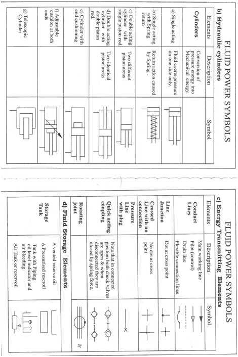
1 Content : 6.1 Hydraulic Circuits 10 Marks Hydraulic symbols Meter in, Meter out. Bleed off, Sequencing. Introduction to electro-hydraulics concept, principles and applications Applications of hydraulic circuits Hydraulic power steering, Hydraulic brakes, milling machine, hydraulic press, 6.2 Simple Pneumatic Circuits. 10 Marks Pneumatic symbols Speed control circuit (Meter in, Meter out), Sequencing. Applications of pneumatic circuits Air brake, Low cost Automation in industries, Pneumatic power tools (drill, hammer, and grinder). Comparison of Hydraulic and pneumatic circuits. 6.1 Hydraulic Circuits 10 Marks Hydraulic & Pneumatic Symbols PTO Page 1
2 Page 2
3 Page 3
4 Page 4
5 Page 5
6 Page 6
7 Page 7
8 Page 8
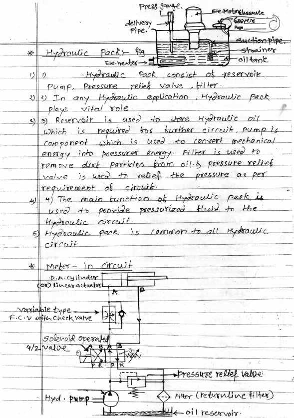
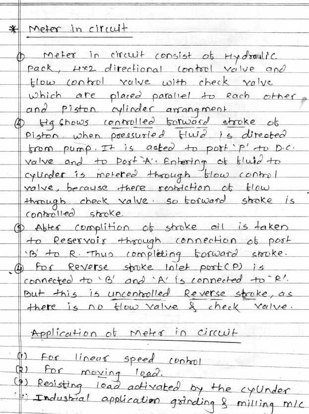
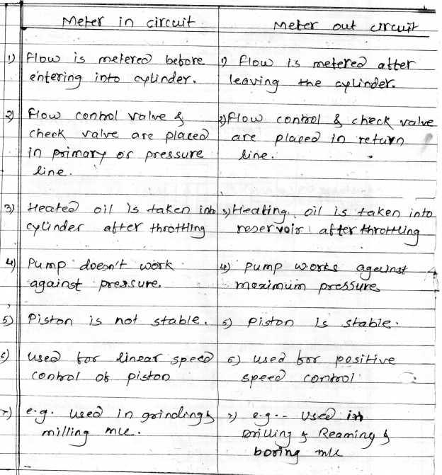
9 OR Meter in circuit : Working : When spool valve is operated pump is connected to blind end of cylinder thus piston moves forward causing work done. During return stroke the fluid returns back through non return valve. Meter in circuit are generally used when load characteristics are constant and positive, in grinding and milling machine. Figure shows circuit connections of a meter in circuit in which the flow control valve is placed in the primary line, directly after load. In meter in circuit speed control is achieved by changing the flow adjustment of flow control valve which controls the oil going to the blind end of the cylinder. Applications : Meter in circuits are used in - Surface Grinder, Milling machine. Page 9
10 OR a) identify the following circuits in figure No 1 b) Make correction if any (Redraw) c) Label it and explain its working d) State its applications a) The given figure is Meter in circuit. Corrected fig as below Page 10
11 Working of Meter in Circuit : Figure shows circuit connections of a meter in circuit in which the flow control valve is placed in the primary line, directly after load. In meter in circuit speed control is achieved by changing the flow adjustment of flow control valve which controls the oil going to the head end of the cylinder. Meter in circuit are generally used when load characteristics are constant and positive. Page 11
12 Page 12
13 Page 13
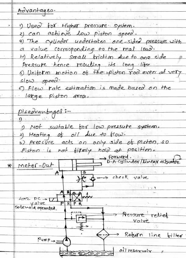
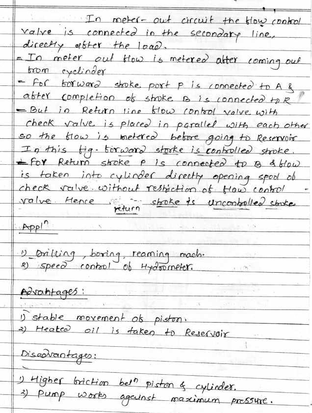
14 OR Meter out circuit : Page 14
15 Page 15
16 By pass (or) Bleed off speed controlling hydraulic circuit : Working : Bleed off circuit does not control the flow going to actuator or flow returning from the actuator. It controls diverted part of the fluid to control the flow. In this circuit Flow control valve are placed in the bypass line. In this circuit neither incoming nor outgoing flow is metered. In this method pressurized fluid coming out of pump is diverted and bypassed to oil reservoir. This circuit is used for controlling linear speed of piston in double acting cylinder. Here speed of piston is depends on difference between pump delivery flow and flow being by passed to tank through flow control valve. Applications : broaching machine shaping machine planing machine hydraulic motor brake circuit 5. Concrete mixer on truck. Page 16
17 OR i) Identify the following circuit in figure No. 1 ii) label and explain its working iii) state its applications i) The figure shows a bleed off circuit. ii) Working : Bleed off circuit does not control the flow going to the actuator or flow returning from the actuator It controls diverted parts of fluid to control the flow in this circuit adjustable throttle is placed bay pass line. Bleed of circuit is also used for controlling the linear speed in double acting cylinder in this circuit neither incoming nor outgoing flow is metered in this method pressurized flow it coming out of pump is diverted and by passed to oil reservoir the speed of piston is depends on difference between pump delivery flow and flow being by pass to reservoir through throttle valve. iii) Applications : 1) Use in hydraulic shaping machine, planer machine. 2) Used for control of broach in broaching machine. 3) It is suitable in constant pressure. Used where precise speed control is not require. Page 17
18 Page 18
19 Page 19
20 Page 20
21 Page 21
22 Page 22

23 Applications of hydraulic circuits : Page 23

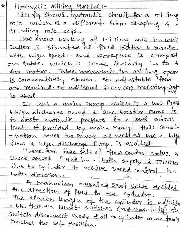
24 Hydraulic circuit for Milling machine : Page 24
25 Page 25
26 Page 26
27 Page 27
28 6.2 Simple Pneumatic Circuits. 10 Marks Draw general layout of pneumatic circuit and label all the parts. 4m Page 28

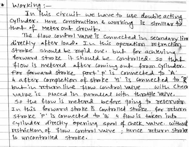
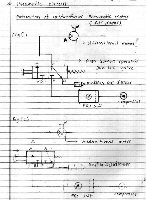
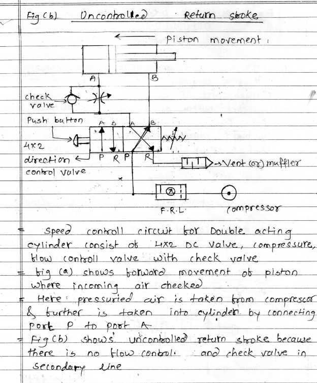
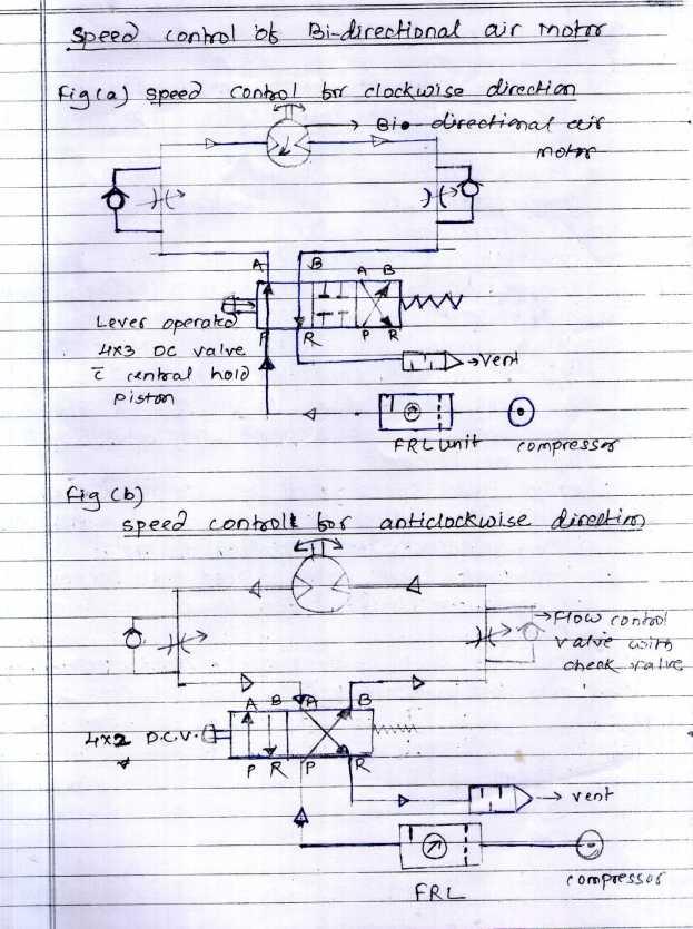
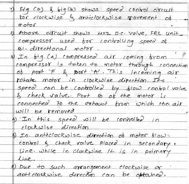
29 Explain with sketch and label pneumatic circuit for speed control of a double acting cylinder. 6m Speed control circuit is used to control the speed of pneumatic actuator; this is achieved by controlling air supplied to the actuators. The air flow to actuator is controlled either the supply line or drain line. In speed control of a cylinder, a flow control valve along with a check valve is normally used, but this combination provides speed control in one direction. In case of speed control in both direction of double acting cylinder, two sets of combination flow control and check valve are used. Speed in a extension and retraction can be changed independently. It should be noted that position of check valves permits free flow of air to the cylinder chambers and throttled flow of air from the chamber. Page 29
30 Page 30
31 Page 31
32 Page 32
33 Page 33
34 Page 34
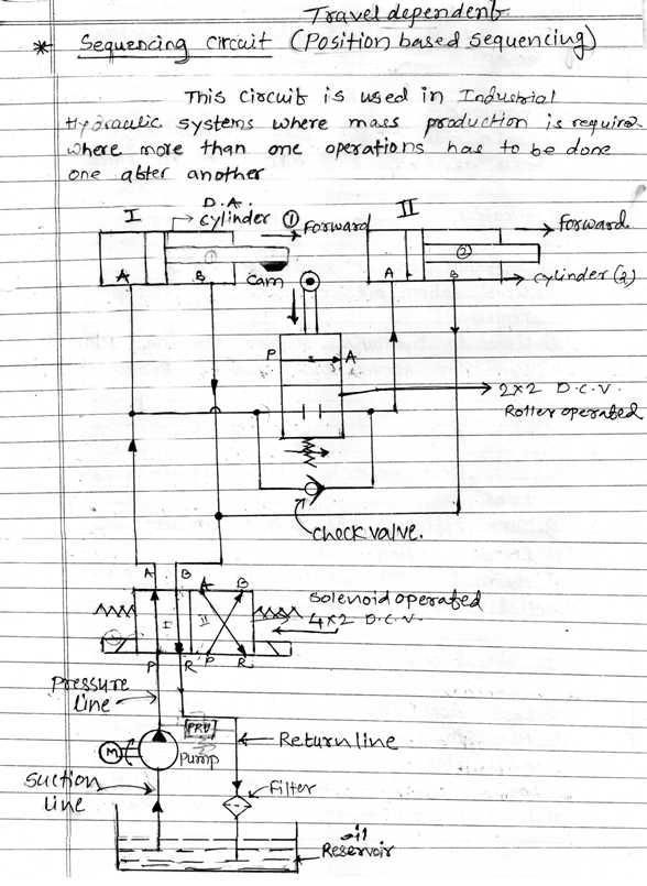
35 Pneumatic Sequencing Circuits : Generally in mass type production industries when two (or) more than two operations / activities are done sequentially then sequencing circuit is used. For getting output we use double acting actuators in a predetermined sequence. Sequencing is done by two methods namely pressure dependents and position dependent. In position based sequencing the cams attached to the actuators (cylinders) operate the valves censing another actuator to move. This method is commonly used in pneumatics. A simple position dependant sequencing of two double acting cylinders in shown in fig when start button is pushed by the operator the cylinder one is extended when it reaches the desired position a 2/2 D.C. valve is actuated which provides impulse to the 4/2 D.C. valve of second cylinder causing it also to extend. Thus the position based sequencing is achieved. Page 35
36 Pressure dependent Pneumatic Sequencing circuit : Construct the pneumatic circuit using sequence valve to control two applications performed in a proper sequence and describe it s working. 8m Pressure dependent sequencing circuit : The circuit is used for drilling a hole in work piece. The sequence operation is a) Clamping of work piece b) Drilling c) Decamping and drill taken out from hole. Page 36
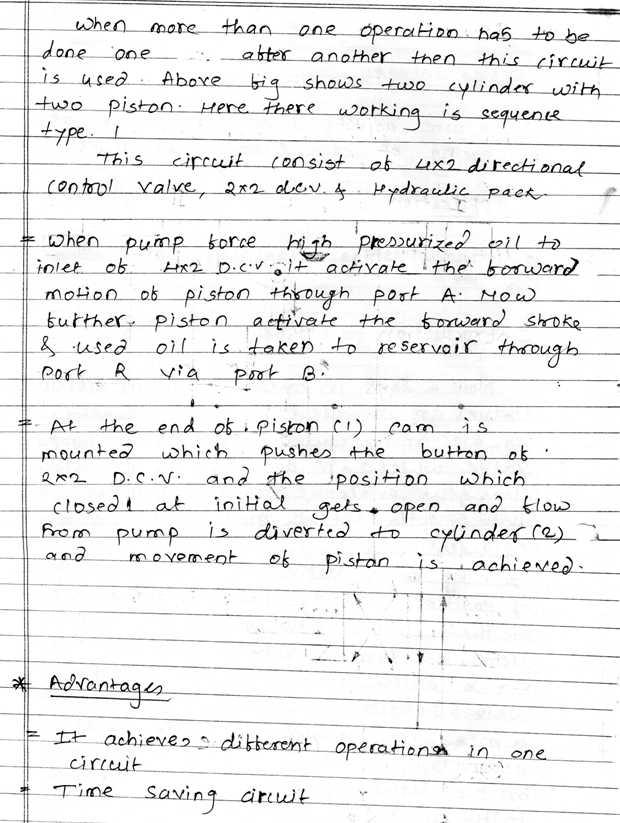
37 The DC valve takes centre position (no 3.) no compressed air supplied to either of cylinder C1 or C2. Now undrilled work piece is kept on fixture seat. The compressed air from compressor is going to vent via DC valve so no movement of cylinder C1 or C 2. Now compressed air start supplying directly to C2 and through sequence valve to C 1 When compressed oil enters through port A2 of cylinder C2 piston will advance and immediately clamps the work piece. At the same time compressed air flow towards port A 1 of cylinder C1 but through the sequence valve. Some higher pressure is set at pressure relief valve of sequence valve when the pressure of flowing air reaches this set value the sequence valve opens and air enters through port A1 into cylinder C1 due to this piston advances comes down so that drilling starts. When operator again operate foot lever of DC valve it takes position 2 and both piston retracts and work piece de-clamps and drill comes out of drilled hole. Page 37
38 Page 38
39 Page 39

40 Application of Compressed Air in Braking System : Page 40
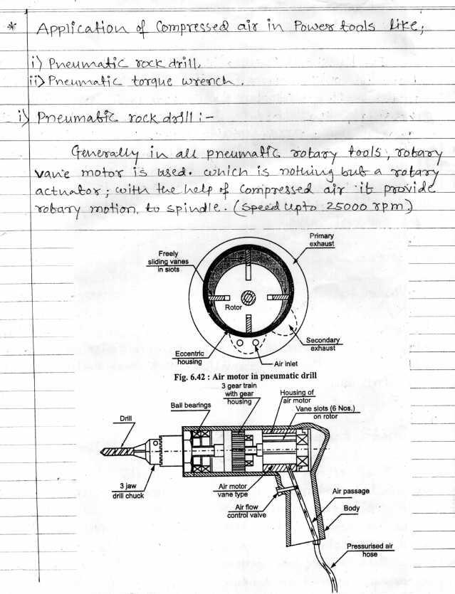
41 Fig shows complete layout of Air Brake System. It consists of Air filter, unloading valve, Air compressor, Air reservoir, Brake valve and 4 numbers brake chamber. Working : The compressor takes atmospheric air through air filter, and compresses the air. This air is stored under pressure in air reservoir. From this reservoir air goes to various accessories of vechile which operates on compressed air. Part of air goes to brake valve. The control of brake valve is done by driver who controls the intensity of braking according to emergency. What are applications of pneumatic circuit? Draw a circuit of any one. 6m (02 marks for application, 03 for figure, 01 for label) applications of pneumatic circuit : 1. Air suspension system. 2. Air braking system 3. Boring machine 4. Pneumatic drill 5. Pneumatic gun 6. Pneumatic wood cutter 7. Pneumatic hammer 8. Pneumatic chain saw Note: credit to suitable diagram of any one appropriate application of pneumatics circuit. Page 41

42 OR Page 42
 Application of hydraulics and pneumatics in automobiles 1. 2. 3. 4. Hydraulic braking system.")
43 Give the application of hydraulics and pneumatics in automobiles. Explain any one of them with neat sketch. 8m (applications- 2 Marks, Sketch- 3 Marks, Suitable explanation- 3 Marks) Application of hydraulics and pneumatics in automobiles Hydraulic braking system. Hydraulic power steering system Air suspension system. Air braking system. Note: credit to suitable explanation of any one appropriate application of hydraulics and pneumatics in automobiles. 2.Hydraulic power steering : Rotary valve type power steering This is used to reduce the turning effort required to steer the wheels. It consist of hydraulic pump, gear box, rotary spool type D.C. valve and hoses. The steering wheel is connected to the one end of rotary spool valve while at other end of valve worm is connected. The worm rotates the nut making the sector to turn which turns the road wheels at angle. When driver turns the steering wheel, the spool valve turns directing the pressurized oil from pump to appropriate side of the nut applying the effort on that side. This helps in reducing the effort of driver. Page 43


44 OR Explain hydraulic power steering with neat labeled sketch. (Optional) Rotary valve type power steering This is used to reduce the turning effort required to steer the wheels. It consist of hydraulic pump, gear box, rotary spool type D.C. valve and hoses. The steering wheel is connected to the one end of rotary spool valve while at other end of valve worm is connected. The worm rotates the nut making the sector to turn which turns the road wheels at angle. When driver turns the steering wheel, the spool valve turns directing the pressurised oil from pump to appropriate side of the nut applying the effort on that side. This helps in reducing the effort of driver. OR Reaction piston type hydraulic steering system (Optional) It consist of piston connected to chassis, a moving cylinder, ball joint connected to drop arm and sliding spool valve The spool valve is operated by ball joint. When the steering wheel is moved to right, the ball joint connected to the drop arm moves the spool valve to right against spring pressure. This allows hydraulic pressure to pass to the rear of the piston. As piston is stationary the pressurized fluid reacts against the piston and pushes the cylinder to the right. The fluid from front of piston is returned to the reservoir. Thus it helps in reducing the effort applied by Driver. Page 44

45 3. Air suspension system : Page 45
46 4) Air Braking System : Fig shows complete layout of Air Brake System. It consists of Air filter, unloading valve, Air compressor, Air reservoir, Brake valve and 4 numbers brake chamber. Working: The compressor takes atmospheric air through air filter, and compresses the air. This air is stored under pressure in air reservoir. From this reservoir air goes to various accessories of vehicle which operates on compressed air. Part of air goes to brake valve. The control of brake valve is done by driver who controls the intensity of braking according to emergency. Page 46
47 Compare hydraulic and pneumatic circuit (any six points) 6m SR. Hydraulic circuit NO. 01 Used for circuits up to 700 bar pressure. 02 Uses hydraulic oil as a medium. 03 Pump is used to pressure the oil. 04 Since hydraulic oil is reused in the circuit hydraulic oil tank is a must and there are return lines. 05 The rigidity of the system using hydraulic circuit is good. Moderate operating cost. Maintenance is critical. Very suitable for accurate speed/feed movement of cutting tool mechanism. Due to non compressibility of oil. The system using hydraulic circuit is not clean due to oil leakages. Weight to pressure ratio is small. Problem of cavitations is serious in hydraulic circuit. Oil is changed as per schedule pneumatic circuit Operative below 10 bar pressure. Uses air as a medium. Compressor is used to pressurize the air. Air is taken from atmosphere and is vented to atmosphere after use. Hence no return lines. Air reservoir is used to store pressurized air. The rigidity of the system using Pneumatic circuit is poor. Operating cost is low. Maintenance is simple. No accuracy in movement. Due to compressibility of air. Pneumatic circuits are very clean. Weight to pressure ratio is high. No problem of cavitations. No need of change of air as per schedule. Limited energy is stored in Large amount of energy stored in air accumulator. tank. Speed is always limited. A very high speed is possible. While working less noise. While working more noise. Oil treatment by oil filter takes place Air treatment is required so use of FRL in power pack. unit in this system. Leakage problem identify by Leakage problem easily identify by observation of dirty and sleepry sound/noisy operation. place. Applications: Hydraulic circuits are Applications: Pneumatic circuits are used in tackling heavy loads, hence used when loads are much lighter. used in earthmoving equipments, Hence used in transferring the light CNC-VMC machines. Hydraulic weight components, vacuum handling in braking,material handling.etc. printing press, food industry. Special purpose tools, Air braking.etc. Page 47
48 Question Bank : Ch no. 6 Hydraulic and Pneumatic circuits 6.1 Hydraulic Circuits 10 Marks 1) Draw a symbol for pressure relief valve and variable speed unidirectional pump.4m 2) Draw the symbols for following i) Filter ii) Hydraulic pump iii) Double acting cylinder iv) 3/2 DC valve. 4m (Q 1&2 E Scheme) 3) Explain meter in type hydraulic circuit. 4m 4) Draw meter-in circuit and explain its working. 8m 5) Draw a neat label sketch of meter-out hydraulic circuit.4m 6) Explain with neat sketch bleed off circuit. 4m 7) Sketch the bleed-off-hydraulic circuit and state any two applications of it.8m 8) Explain construction and working of hydraulic power steering. 9) Explain hydraulic power steering with neat labeled sketch. 10 Draw layout of hydraulic steering system. Explain its working. 6m 11 Draw the neat labeled layout of hydraulic braking system and explain its working. 8m 12 a) identify the following circuits in figure No 1 b) Make correction if any (Redraw) c) Label it and explain its working d) State its applications Page 48
49 13) 6.2 i) Identify the following circuit in figure No. 1 ii) label and explain its working iii) state its applications. Simple Pneumatic Circuits. 10 Marks 14) Draw pneumatic symbols of following i) 4x3 DC valve ii) Tandem cylinder iii) Variable flow control valve iv) Bi-directional air motor. ( E Scheme) 15) Sketch and label pneumatic circuit for speed control of a double acting cylinder.6m 16) Explain sequencing pneumatic circuits with neat sketch. 8m 17) Draw general layout of pneumatic circuit and label all the parts. 4m 18) Explain with neat sketch pneumatic speed control circuits.4m 19) What are applications of pneumatic circuit? Draw a circuit of any one. 6m 20) Draw and explain pneumatic circuit to control the speed of double acting cylinder. 6m 21) Construct the pneumatic circuit using sequence valve to control two applications performed in a proper sequence and describe it s working. 8m 22) Draw general layout of pneumatic system and label the components. 4m Combination Questions : (On Hydraulics & Pneumatics System) 23) Compare hydraulic and pneumatic circuit on the basis of - fluid used, ease of operation, noise, speed, cost, application. 6m 24) Give the application of hydraulics and pneumatics in automobiles. Explain any one of them with neat sketch. 8m 25) Compare hydraulic and pneumatic circuit ( any six points) 6m Page 49
CH.4 Basic Components of Hydraulic and Pneumatic System/16 M HAP/17522/AE5G
 Content : 4.1 Hydraulic and Pneumatic actuators. 10 Marks Hydraulic Actuators - Hydraulic cylinders (single, double acting and telescopic) construction and working, Hydraulic motors (gear and piston type)
WINTER 14 EXAMINATION Subject Code: Model Answer Page No: 1/20
 Subject Code: 17522 Model Answer Page No: 1/20 Important Instructions to examiners: 1) The answers should be examined by key words and not as word-to-word as given in the model answer scheme. 2) The model
Experiments on Hydraulic and Pneumatic circuit trainers HYDRAULIC CIRCUITS:
 Experiments on Hydraulic and Pneumatic circuit trainers HYDRAULIC CIRCUITS: Hydraulic circuits are used in high power and high load applications such as earth moving equipment. The pressure used in industrial
I) Clamping the work piece II) Drilling the work piece. III) Unclamping the work piece. 10
 Clamping the work piece II) Drilling the work piece. III) Unclamping the work piece. 10") Seventh Semester B.E. III IA Test, 2014 USN 1 P E M E PES INSTITUTE OF TECHNOLOGY (Bangalore South Campus) (Hosur Road, 1KM before Electronic City, Bangalore-560 100) Department of Mechanical Engineering
Seventh Semester B.E. III IA Test, 2014 USN 1 P E M E PES INSTITUTE OF TECHNOLOGY (Bangalore South Campus) (Hosur Road, 1KM before Electronic City, Bangalore-560 100) Department of Mechanical Engineering
2. Hydraulic Valves, Actuators and Accessories. 24 Marks
 2. Hydraulic Valves, Actuators and Accessories 24 Marks Co related to chapter 602.2 Describe working principle of various components used in hydraulic & pneumatic systems. 602.3 Choose valves, actuators
DEPARTMENT OF MECHANICAL ENGINEERING QUESTION BANK. Sub. Code/Name: ME1305 Applied Hydraulics and Pneumatics Year/Sem: III/V
 DEPARTMENT OF MECHANICAL ENGINEERING QUESTION BANK Sub. Code/Name: ME1305 Applied Hydraulics and Pneumatics Year/Sem: III/V UNIT-1 FLUID POWER SYSTEMS AND FUNDAMENTALS 1. Define fluid power? 2. List the
Module 5: Valves. CDX Diesel Hydraulics. Terms and Definitions. Categories of Valves. Types of Pressure Control Valves
 Terms and Definitions Categories of Valves Types of Pressure Control Valves Types and Operation of Pressure Relief Valves Operation of an Unloading Valve Operation of a Sequencing Valve Operation of a
Marine Engineering Exam Resource Review of Hydraulics
 1. What is Pascal s law? Pressure confined on a confined fluid will transmit the pressure in all directions and act with equal force on all areas at right angles. 2. How does the law pertain to hydraulics?
Test Which component has the highest Energy Density? A. Accumulator. B. Battery. C. Capacitor. D. Spring.
 Test 1 1. Which statement is True? A. Pneumatic systems are more suitable than hydraulic systems to drive powerful machines. B. Mechanical systems transfer energy for longer distances than hydraulic systems.
Introduction. Pre-Lab
 The University Of Jordan School of Engineering Mechatronics Engineering Department Fluid Power Engineering Lab Experiments No.2 Pneumatic Control of a Double-acting Cylinder Objective: Students will be
What does pressure refer to in relation to hydrostatics and what is it dependent on?
 Question 1 [3 Marks] What does pressure refer to in relation to hydrostatics and what is it dependent on? Question 2 [14 Marks] Make a circuit diagram of a regular hydraulic plant that is used to control
FRL unit consist of Filterations, Regulators and Lubricator unit.
 4.1 AIR CONTROL 4.1.1 Fluid Conditioner FRL unit consist of Filterations, Regulators and Lubricator unit. It is also known as Air Service Unit. Primary function is to provide clean air at optimal pressure
PNEUMATIC & HYDRAULIC SYSTEMS
 PNEUMATIC & HYDRAULIC SYSTEMS CHAPTER SIX PNEUMATIC SYSTEM DESIGN AND DEVELOPMENT Dr. Ibrahim Naimi Symbols And Standards In Pneumatics The development of pneumatic systems is assisted by a uniform approach
Design and Fabrication of Sequencing Circuit with Single Double Acting Cylinder
 Design and Fabrication of Sequencing Circuit with Single Double Acting Cylinder V.G.Vijaya Department of Mechatronics Engineering, Bharath University, Chennai 600073, India ABSTRACT: This project deals
LESSON 2 BASIC CONSTRUCTION AND OPERATION OF HYDRAULIC ACTUATING DEVICES, FLOW CONTROL, AND DIRECTIONAL DEVICES. STP Tasks:
 LESSON 2 BASIC CONSTRUCTION AND OPERATION OF HYDRAULIC ACTUATING DEVICES, FLOW CONTROL, AND DIRECTIONAL DEVICES STP Tasks: 552-758-1003 552-758-1071 OVERVIEW LESSON DESCRIPTION: In this lesson you will
Projekthandbuch. Project Manual Industriehydraulik. Industrial Hydraulics RE 00846/ Trainee's manual. Schülerhandbuch
 Electric Drives and Controls Hydraulics Linear Motion and Assembly Technologies Pneumatics Service Projekthandbuch Project Manual Industriehydraulik Industrial Hydraulics RE 00846/04.07 Schülerhandbuch
Lesson 5: Directional Control Valves
 : Directional Control Valves Basic Hydraulic Systems Hydraulic Fluids Hydraulic Tank Hydraulic Pumps and Motors Pressure Control Valves Directional Control Valves Flow Control Valves Cylinders : Directional
FLUID POWER P&IDs. IDENTIFY the symbols used on engineering fluid power drawings for the following components:
 FLUID POWER P&IDs Fluid power diagrams and schematics require an independent review because they use a unique set of symbols and conventions. EO 1.11 IDENTIFY the symbols used on engineering fluid power
PRESENTATION ON HYDRAULIC BASED COMPONENT
 PRESENTATION ON HYDRAULIC BASED COMPONENT 1.HYDRAULIC CRANE 2.HYDRAULIC LIFT 3.HYDRAULIC ACCUMULATOR 4.HYDRAULIC INTENSIFIER 5.JET PUMP PRESENTED BY: GAURAV SHARMA HYDRAULIC CRANE The hydraulic crane is
Basic Hydraulics. Module 2: Actuators and directional control valves. Curriculum Development Unit PREPARED BY. August 2013
 Basic Hydraulics Module 2: Actuators and directional control valves PREPARED BY Curriculum Development Unit August 2013 Applied Technology High Schools, 2013 ATM-312 Basic Hydraulics Module 2: Actuators
Module 6 Assignment Part A
 Module 6 Assignment Part A TOTAL MARKS Part A = 192 TOTAL QUESTIONS Part A = 36 Question 1 [3 Marks] What does pressure refer to in relation to hydrostatics and what is it dependent on? Question 2 [14
Industrial Pneumatic Systems Syllabus [Detailed]
![Industrial Pneumatic Systems Syllabus [Detailed]](/thumbs/81/83340511.jpg "Industrial Pneumatic Systems Syllabus [Detailed]") TECHNICAL TRAINING - SWAPPING DOWNTIME FOR PRODUCTIVITY! Industrial Pneumatic Systems Syllabus [Detailed] 1. Fundamentals of Fluid Power Systems. The three states of matter. Definition of a fluid. Derivation
TECHNICAL TRAINING - SWAPPING DOWNTIME FOR PRODUCTIVITY! Industrial Pneumatic Systems Syllabus [Detailed] 1. Fundamentals of Fluid Power Systems. The three states of matter. Definition of a fluid. Derivation
Project Manual Industrial Hydraulics
 Electric Drives and Controls Hydraulics Linear Motion and Assembly Technologies Pneumatics Service Project Manual Industrial Hydraulics RE 00845/04.07 Trainer s manual Electric Drives and Controls Hydraulics
Department of Mechanical Engineering UBMC701 AUTOMOBILE ENGINEERING QUESTION BANK VEHICLE STRUCTURE AND ENGINES. Part A (Two Marks Questions)
") Department of Mechanical Engineering UBMC701 AUTOMOBILE ENGINEERING QUESTION BANK UNIT- I VEHICLE STRUCTURE AND ENGINES 1. Define Automobile. Give the typical specifications of an automobile 2. Name the
Department of Mechanical Engineering UBMC701 AUTOMOBILE ENGINEERING QUESTION BANK UNIT- I VEHICLE STRUCTURE AND ENGINES 1. Define Automobile. Give the typical specifications of an automobile 2. Name the
Torque Converter, Transmission Pump, Screen And Filter
 Page 13 of 27 Transmission Hydraulic System In Forward (Engine Running - Type 2 & 3 Control Valve Shown) (4) Transmission control valve. (5) Neutralizer valve. (6) Neutralizer solenoid. (7) Flow control
DO NOT INSTALL, OPERATE, OR MAINTAIN AN ATI PRODUCT UNLESS TRAINED AND QUALIFIED IN PRODUCT AND ACCESSORY INSTALLATION, OPERATION AND MAINTENANCE.
 IOM Supplement IOMS003 ATI HO1/HO2 HYDRAULIC OVERRIDE Scope of Supplement This supplement is intended to assist those who are involved with the installation, operation and maintenance of ATI Linear Actuators
Applications of Pneumatics and Hydraulics
 Unit 24: Applications of Pneumatics and Hydraulics Unit code: J/601/1496 QCF level: 4 Credit value: 15 Aim This unit aims to extend learners understanding of pneumatic and hydraulic fluid power systems
The figure 269J is a double seal mix-proof piston valve, used for product isolation, where safe separation of process and C.I.P. fluids is required.
 The figure 269J is a double seal mix-proof piston valve, used for product isolation, where safe separation of process and C.I.P. fluids is required. Features Product contact parts manufactured from high
Syslog Technologies Innovative Thoughts
 HYDRO-PNEUMATIC VICE WITH PRESSURE BOOSTER SYNOPSIS This project deals with the design and fabrication of the hydro pneumatic vice with an air-to-hydraulic pressure booster, the hydro pneumatic vice is
t2_ il PioC Oper. led Relet Valve Symbol ~~~ CHAPTER 12 Pilot Operated Pressure Control Valves
 CHAPTER 12 Pilot Operated Pressure Control Valves Unlike a simple or direct operated pressure control valve, where a spool is held biased by spring pressure only, a pilot operated valve has its spool biased
DESCRIPTION & OPERATION
 DESCRIPTION & OPERATION BRAKE BOOSTER Delco-Moraine Single Diaphragm A combined vacuum-hydraulic unit which uses a combination of intake manifold vacuum and atmospheric pressure to provide power assist.
Cambridge International Examinations Cambridge International General Certificate of Secondary Education
 www.xtremepapers.com Cambridge International Examinations Cambridge International General Certificate of Secondary Education *2641043214* DESIGN AND TECHNOLOGY 0445/43 Paper 4 Systems and Control October/November
Content : 4.1 Brayton cycle-p.v. diagram and thermal efficiency. 4Marks Classification of gas turbines.
 Content : 4.1 Brayton cycle-p.v. diagram and thermal efficiency. 4Marks Classification of gas turbines. 4.2 Construction and working of gas turbines i) Open cycle ii) Closed cycle gas Turbines, P.V. and
Chapter. Steering System Technology
 Chapter 78 Steering System Technology Objectives After studying this chapter, you will be able to: Explain the operating principles of steering systems. Identify the major parts of a steering system. Compare
Ball Screw Unit for Automotive Electro-actuation
 New Product Ball Screw Unit for Automotive Electro-actuation Koji TATEISHI In the automotive market, numerous new hybrid cars and engines with low fuel consumption and low emissions have been developed
Content. Chapter 1 Hydraulic energy converters... 10
 Content Chapter 1 Hydraulic energy converters... 10 1.1 List of symbols... 13 1.2 Hydraulic pump types, constant output... 14 1.2.1 External gear pumps... 16 1.2.2 Internal gear pumps... 17 1.2.3 Vane
Module 6. Actuators. Version 2 EE IIT, Kharagpur 1
 Module 6 ctuators Version 2 II, Kharagpur 1 Lesson 28 Industrial Hydraulic ircuits Version 2 II, Kharagpur 2 Lesson Objectives fter learning the lesson students should be able to escribe typical industrial
Learning System for Automation and Communications. Electropneumatics. Workbook Basic Level S1 K1 K1 Y1
 Learning System for Automation and Communications Electropneumatics Workbook Basic Level 1 2 3 S1 K1 K1 S2 K1 094005 Order no. 094005 Description: TEACHW.E-PNEUM. Designation: D.S201-C-GB Edition: 08/1993
Actuators and directional control valves
 Actuators and directional control valves 1. Differentiate between the main types of directional control valves. 2. Demonstrate the function and uses of 3/2 way valve, push button actuated. 3. Demonstrate
Basic Hydraulics and Pneumatics
 Basic Hydraulics and Pneumatics Module 2: Actuators and directional control valves PREPARED BY Academic Services August 2011 Applied Technology High Schools, 2011 ATM 1122 Basic Hydraulics Module 2: Actuators
Unit HV04K Knowledge of Heavy Vehicle Chassis Units and Components
 Assessment Requirements Unit HV04K Knowledge of Heavy Vehicle Chassis Units and Components Content: Chassis layouts i. types of chassis ii. axle configurations iii. rear steered axles iv. self-steered
Pneumatic & Hydraulic SYSTEMS
 Pneumatic & Hydraulic SYSTEMS CHAPTER EIGHT HYDRAULIC PUMPS AND ACTUATORS Dr. Ibrahim Naimi The higher the discharge pressure, the lower the volumetric efficiency because internal leakage
CDI Revision Notes Term 1 ( ) Grade 12 Advanced Unit 2 Mechanical Systems
 Grade 12 Advanced Unit 2 Mechanical Systems") CDI Revision Notes Term 1 (2017 2018) Grade 12 Advanced Unit 2 Mechanical Systems STUDENT INSTRUCTIONS Student must attempt all questions. For this examination, you must have: (a) An ink pen blue. (b)
CDI Revision Notes Term 1 (2017 2018) Grade 12 Advanced Unit 2 Mechanical Systems STUDENT INSTRUCTIONS Student must attempt all questions. For this examination, you must have: (a) An ink pen blue. (b)
PAST EXAM PAPER & MEMO N3 ABOUT THE QUESTION PAPERS:
 EKURHULENI TECH COLLEGE. No. 3 Mogale Square, Krugersdorp. Website: www. ekurhulenitech.co.za Email: info@ekurhulenitech.co.za TEL: 011 040 7343 CELL: 073 770 3028/060 715 4529 PAST EXAM PAPER & MEMO N3
Design and Fabrication of Pneumatic Sheet Metal Cutting Machine
 Design and Fabrication of Pneumatic Sheet Metal Cutting Machine Prof. M. W. Andure 1, Suraj V Bhosale 2, Gajanan S Ghute 3, Nikita H Dudhe 4, Ashish G Ingle 5 1, 2, 3, 4, 5 Department of Mechanical Engineering
: Automation Laboratory 1
 Table A.1 shows elements found in FluidSIM library with a brief description for each of them. Compressed air supply The compressed air supply provides the needed compressed air. It contains a pressure
Input, Control and Processing elements
 PNEUMATIC & HYDRAULIC SYSTEMS CHAPTER FIVE Input, Control and Processing elements Dr. Ibrahim Naimi Valves The function of valves is to control the fluid path or the pressure or the flow rate. Depending
Chapter 17. Work Performers of Pneumatic Systems. Cylinders, Motors, and Other Devices
 Chapter 17 Work Performers of Pneumatic Systems Cylinders, Motors, and Other Devices 1 Objectives Describe the construction features of basic, pneumatic linear and rotary actuators. Compare the design
The pneumatic circuit and parts' list needed to perform this operation are shown by Figure C.1.
 Introduction In session 1 you have learned about pneumatic systems and their main components. In addition to that your lab instructor has introduced to you how to use FluidSIM software. During this appendix
Hygienic Products Figure 267J/268J Single Seal Piston Valves
 The figure 267J and 268J valves are single seal piston valves, used to control process or C.I.P. fluids. F267J for isolating. F268J for diverting or converging flows. Features Product contact parts are
Instructor Training Manual. Chapter 6 HYDRAULICS & PNEUMATICS
 Instructor Training Manual Chapter 6 HYDRAULICS & PNEUMATICS Learning Objectives 1. The purpose of this chapter is to provide a basic introduction to the principles of hydraulics & pneumatics and their
Design V260 Ball Control Valve
 Product Bulletin D102352X012 V260 Valve Design V260 Ball Control Valve The Design V260 is a full bore control valve designed from the ground up with features for optimized pressure, flow and process control.
 DEPARTMENT OF MECHANICAL ENGINEERING Subject code: ME6601 Subject Name: DESIGN OF TRANSMISSION SYSTEMS UNIT-I DESIGN OF TRANSMISSION SYSTEMS FOR FLEXIBLE ELEMENTS 1. What is the effect of centre distance
Definitions of Technical Terms
 Definitions of Technical Terms ABSOLUTE A measure having as it s zero point of base the complete absence of the entity being measured. ABSOLUTE PRESSURE A pressure scale with zero point at a perfect vacuum.
Operating instructions Form no safety definitions
 Operating instructions Form no. 1000437 safety definitions safety symbols are used to identify any action or lack of action that can cause personal injury. Your reading and understanding of these safety
Chapter 33 Fundamentals of Hydraulic and Air-Over-Hydraulic Braking Systems
 Chapter 33 Fundamentals of Hydraulic and Air-Over-Hydraulic Braking Systems Introduction Vehicle s braking system must meet the following requirements: To adequately and safely reduce a vehicle s speed,
Pneumatic Trainer Kit
 Pneumatic Trainer Kit Prof. N.R. Pawar, Nilesh Bhalerao, JitendraSingh Chouhan, Neha Muley, Ujwala Kamble Department of Mechanical Engineering, D.Y.Patil College of Engineering, Akurdi, Pune India. Keywords:-
Hydraulic Master Cylinders
 Hydraulic Master Cylinders flange mount and side mount, straight-bore and two-stage cylinders Hydraulic Cylinders for Mobile and Industrial Applications Why choose MICO? MICO, Incorporated designs, manufactures
Hours / 100 Marks Seat No.
 17412 16117 3 Hours / 100 Seat No. Instructions (1) All Questions are Compulsory. (2) Answer each next main Question on a new page. (3) Illustrate your answers with neat sketches wherever necessary. (4)
LECTURE 24 TO 26 - HYDRAULIC CIRCUIT DESIGN FREQUENTLY ASKED QUESTIONS
 LECUE 24 O 26 - HYDAULIC CICUI DESIGN EQUENLY ASKED QUESIONS 1. List three important considerations to be taken into account while designing a hydraulic circuit here are 3 important considerations in designing
OPERATION AND PARTS MANUAL
 OPERATION AND PARTS MANUAL MODEL NUMBER : PART NUMBER : TAP- IN KIT 5100-5151 BAYNE MACHINE WORKS, INC. PHONE: (864) 288-3877 910 FORK SHOALS ROAD TOLL FREE: (800) 535-2671 GREENVILLE S.C., 29605 FAX:
Fisher V260 Ball Control Valve
 Fisher V260 Ball Control Valve The Fisher V260 is a full-bore control valve designed from the ground up with features for optimized pressure, flow and process control. An integral drilled attenuator controls
Using Multiple Cylinder Engines
 Lesson A6 6 Using Multiple Cylinder Engines Unit A. Mechanical Systems and Technology Problem Area 6. Agricultural Power Systems Lesson 6. Using Multiple Cylinder Engines New Mexico Content Standard: Pathway
Appendix A. Standard Symbols for Hydraulic Components
 Table B.1 Flow lines Appendix A Standard Symbols for Components Continuous flow E Pilot connection L L>10E E Drain connection L L
REVERSING PUMPSET TABLE OF CONTENTS. 1. GENERAL INFORMATION... p TECHNICAL SPECIFICATIONS and APPLICATION... p. 02
 REVERSING PUMPSET HRP35 TABLE OF CONTENTS 1. GENERAL INFORMATION... p. 01 2. TECHNICAL SPECIFICATIONS and APPLICATION... p. 02 3. DESCRIPTION... p. 03 3.1 General 3.2 Motor 3.3 Pump 3.4 Valve Block and
Name common, basic subsystems that compose
 Chapter 13 Applying Hydraulic Power Typical Circuits and Systems 1 Objectives Name common, basic subsystems that compose complex hydraulic systems and describe their function. Compare the design and operation
Engineering Diploma Resource Guide ST280 ETP Hydraulics (Engineering)
") Engineering Diploma Resource Guide ST80 ETP Hydraulics (Engineering) Introduction Hydraulic systems are a fundamental aspect of engineering. Utilised across a variety of sectors including aviation, construction,
Engineering Diploma Resource Guide ST80 ETP Hydraulics (Engineering) Introduction Hydraulic systems are a fundamental aspect of engineering. Utilised across a variety of sectors including aviation, construction,
CENTAC Inlet and Bypass Valve Positioners
 CENTAC Inlet and Bypass Valve Positioners INGERSOLL-RAND AIR COMPRESSORS INLET AND BYPASS VALVE POSITIONERS Copyright Notice Copyright 1992, 1999 Ingersoll-Rand Company THIS CONTENTS OF THIS MANUAL ARE
Before you go through this booklet, we request you to go through the following general instruction before commissioning your hydraulic systems.
 Hello, We are proud to be on your suppliers list. During few years we came to know that most of our customers are satisfied by Yuken Hydraulic Products but some of our customers had minor problems and
LECTURE 15 TO 17 DIRECTIONAL CONTROL VALVES FREQUENTLY ASKED QUESTIONS
 LECURE 15 O 17 DIRECIONL CONROL VLVES FREQUENLY SKED QUESIONS 1. Explain briefly the function of directional control valves o o start, stop, accelerate, decelerate and change the direction of motion of
CURRICULUM BOSCH-REXROTH (CENTRE OF EXCELLENCE) GANPAT UNIVERSITY
 GANPAT UNIVERSITY") ANNEXURE - A CURRICULUM BOSCH-REXROTH (CENTRE OF EXCELLENCE) Host Institute: GANPAT UNIVERSITY Contents of Basic Industrial Pneumatics -----------------------------------------------------------------------------------------------------------------
ANNEXURE - A CURRICULUM BOSCH-REXROTH (CENTRE OF EXCELLENCE) Host Institute: GANPAT UNIVERSITY Contents of Basic Industrial Pneumatics -----------------------------------------------------------------------------------------------------------------
LEVEL 1/2 CAMBRIDGE NATIONAL AWARD/CERTIFICATE IN PRINCIPLES IN ENGINEERING AND ENGINEERING BUSINESS. Candidate Surname
 SPECIMEN LEVEL 1/2 CAMBRIDGE NATIONAL AWARD/CERTIFICATE IN PRINCIPLES IN ENGINEERING AND ENGINEERING BUSINESS R101: Engineering Principles Candidates answer on the Question Paper OCR Supplied Materials:
SUMMARY KIT PNEUMATIC MOTION
 SUMMARY G1 P CONFIGURABLE (KIT PMC) G1.2 P READY (KIT PMR) G1.3 P CUSTOM G1.9 SUMMARY G1.1 CONFIGURABLE (KIT PMC) An on-line configurator is provided for the ease-and-quick selection of the cylinder, the
Section 6.1. Implement Circuit - General System. General: Implement Control Valve:
 Section 6.1 Implement Circuit - General System General: Implement Circuit... 6.1.3 Implement Pump Breakdown... 6.1.4 Operational Description: General... 6.1.5 Compensator Control... 6.1.6 Standby Condition...
Unit C: Agricultural Power Systems. Lesson 6: Using Multiple Cylinder Engines
 Unit C: Agricultural Power Systems Lesson 6: Using Multiple Cylinder Engines Student Learning Objectives: Instruction in this lesson should result in students achieving the following objectives: 1. Explain
Track Drive Circuit - General System. Simplified Travel Circuit Diagrams: Neutral Controls Forward Travel Reverse Travel
 Section 7.1 Track Drive Circuit - General System Simplified Travel Circuit Diagrams: Neutral Controls... 7.1.2 Forward Travel... 7.1.4 Reverse Travel... 7.1.5 General... 7.1.3 Track Drive Circuit: General...
WEB CHAPTER. Fluid Power THE ENGINEERING DESIGN APPLICATION OBJECTIVES
 WEB CHAPTER Fluid Power 1 OBJECTIVES After completing this chapter, you will: Calculate unknown values in given fluid power applications. Draw graphic diagrams of hydraulic circuits. Make graphic diagrams
Pneumatic Balancers 50 to 2000 lbs (22 to 909 kg) Capacity
 Capacity") The Strength Behind Material Handling Technology Meeting the needs of today s material handling applications requires an ergonomic lift assist that interacts with the operator. The Balancer offers lifting
The Strength Behind Material Handling Technology Meeting the needs of today s material handling applications requires an ergonomic lift assist that interacts with the operator. The Balancer offers lifting
Operating & Maintenance Manual For Steam Conditioning Valve
 For Steam Conditioning Valve 1 Table of Contents 1.0 Introduction 3 2.0 Product description 3 3.0 Safety Instruction 4 4.0 Installation and Commissioning 5 5.0 Valve Disassembly 6 6.0 Maintenance 6 7.0
Nomenclature... xi Hydraulic Laws, Theorems, and Equations...xii
 Nomenclature... xi Hydraulic Laws, Theorems, and Equations...xii 1 Introduction 1.1 Component Design Perspective...1 1.2 Hydraulic Power Evolution...2 1.3 Hydraulic Applications...6 1.4 Component Design
DROPS INSTEAD OF LITRES!
 MQL MINIMUM QUANTITY LUBRICATION. DROPS INSTEAD OF LITRES! 1 The Allube Micro-lubrication Systems are designed for use primarily in the varied metal cutting and forming processes to enable the replacement
NOVAPLEX Integral. Process Diaphragm Pumps. motralec
 motralec 4 rue Lavoisier. ZA Lavoisier. 95223 HERBLAY CEDEX Tel. : 01.39.97.65.10 / Fax. : 01.39.97.68.48 Demande de prix / e-mail : service-commercial@motralec.com www.motralec.com NOVAPLEX Integral Process
SECTION 4A BRAKE SYSTEM TABLE OF CONTENTS
 SECTION 4A BRAKE SYSTEM TABLE OF CONTENTS Description and Operation... 4A-2 Braking System Testing... 4A-2 Hydraulic Brake System... 4A-2 Brake Pedal... 4A-2 Master Cylinder... 4A-2 Brake Booster... 4A-3
Levelling valve
 Levelling valve 464 006 Application Purpose Maintenance Vehicles with conventionally controlled air-suspension. Control of a constant ride height of the chassis by charging the air-suspension while compressing
Hydro-Max Hydraulic Brake Booster and Master Cylinder. Technical Manual
 Hydro-Max Hydraulic Brake Booster and Master Cylinder Technical Manual * 5+0 Important Service Notes The information in this publication was current at the time of printing. The information presented in
Section 35 Chapter 2 HYDRAULIC SYSTEM HOW IT WORKS AND TROUBLESHOOTING NH
 Section 35 Chapter HYDRAULIC SYSTEM HOW IT WORKS AND TROUBLESHOOTING 6-80NH TABLE OF CONTENTS GENERAL INTRODUCTION... 35-3 Hydraulic Pumps... 35-3 Standard Flow PFC Pump Layout... 35-5 MegaFlow PFC Pump
Savitribai Phule Pune University, Pune, India.
 Automation of Mechanisms in B-Test Fixture for Process Cycle Time Improvement Jagdish Kattimani 1, Dnyaneshwar Kedar 2, Vikramaditya Patil 3, Mukesh Chhanwal 4, Nitin Gupte 5 # Department of Mechanical
WINTER 14 EXAMINATION
 WINTER 14 EXAMINATION Subject Code: 17413(EME) Model Answer Important Instructions to examiners: 1) The answers should be examined by key words and not as word-to-word as given in the model answer scheme.
ADVANCED CUSTOMIZED ELECTRO PNEUMATIC TRAINER (PRODUCT CODE: SAP 20B)
") The Advanced Customized Electro Pneumatic Trainer (SAP 20B) is capable of being used to demonstrate the design, construction and application of electro-pneumatic components and circuits. Objectives:- The
The Advanced Customized Electro Pneumatic Trainer (SAP 20B) is capable of being used to demonstrate the design, construction and application of electro-pneumatic components and circuits. Objectives:- The
Topic 1. Basics of Oil Hydraulic Systems
 Topic 1. Basics of Oil Hydraulic Systems Fluid power Fluid power is the technology that deals with the generation, control and transmission of forces and movement of mechanical element or system with the
Introduction. General Information. Systems Operation
 Systems Operation Introduction Reference: For illustrated Specifications, refer to the Specifications For 416, 426, 428, 436, 438, & Series II Backhoe Loaders Transmission, Form No. SENR3131. If the specifications
VARIABLE VOLUME RESERVOIR (VVR) FOR INDUSTRIAL AND MOBILE APPLICATIONS
 FOR INDUSTRIAL AND MOBILE APPLICATIONS") SOBACOR inc. 812 boul. Industriel Bois-des-Filion, Québec Canada J6Z 0A3 450-965-9669 450-965-9690 sobacor@sympatico.ca www.sobacor.com VARIABLE VOLUME RESERVOIR (VVR) FOR INDUSTRIAL AND MOBILE APPLICATIONS
SOBACOR inc. 812 boul. Industriel Bois-des-Filion, Québec Canada J6Z 0A3 450-965-9669 450-965-9690 sobacor@sympatico.ca www.sobacor.com VARIABLE VOLUME RESERVOIR (VVR) FOR INDUSTRIAL AND MOBILE APPLICATIONS
Subject: Pneumatic Training Kit with portable Air Compressor
 MSME TOOL ROOM: HYDERABAD (CENTRAL INSTITUTE OF TOOL DESIGN) Balanagar, Hyderabad 500 037 TEL.NO.23772747, 23776168 FAX No.0-4023772658 E-mail:citdpurchase@citdindia.org Visit us: www.citdindia.org. TENDER
Hydraulic energy control, conductive part
 Chapter 2 2 Hydraulic energy control, conductive part Chapter 2 Hydraulic energy control, conductive part To get the hydraulic energy generated by the hydraulic pump to the actuator, cylinder or hydraulic
VELAN TRUNNION-MOUNTED
 VELAN TRUNNION-MOUNTED Velan s standard trunnion-mounted ball valves offer increased value by incorporating advanced design features. TRUNNION-MOUNTED BALL The ball is fixed and the seat rings are floating,
CAB TILT HYDRAULIC SYSTEM
 OPERATION, MAINTENANCE and SERVICE INSTRUCTIONS CAB TILT HYDRAULIC SYSTEM WITH POWER-PACKER PUMP, CYLINDERS and LATCHES A division of Actuant Corporation 1-800-745-4142 1 www.powerpackerus.com Notice The
CD CHAPTER. Fluid Power THE ENGINEERING DESIGN APPLICATION LEARNING OBJECTIVES
 CD CHAPTER Fluid Power 1 LEARNING OBJECTIVES After completing this chapter, you will: Calculate unknown values in given fluid power applications. Draw graphic diagrams of hydraulic circuits. Make graphic
Water Treatment Plant Maintenance Considerations. Operation and Maintenance. Types of Maintenance 5/1/15
 Water Treatment Plant Maintenance 1 Operation and Maintenance Purpose of O&M maintain design functionality (capacity) restore the system components to their original condition and thus functionality. Effective
O500LE & O500RF OVERVIEW OF READING MB PNEUMATIC DIAGRAMS AND PORT IDENTIFICATION. DaimlerChrysler Australia / Pacific Service & Parts CV
 OVERVIEW OF READING MB PNEUMATIC DIAGRAMS AND PORT IDENTIFICATION Understanding Pneumatic Diagrams Port Numbering Mercedes-Benz use a standard method for that allows for easy identification of the pneumatic
Section 6.1. Implement Circuit - General System. General: TF Configuration TB Configurations Implement Control Valve:
 Section 6.1 Implement Circuit - General System General: TF Configuration... 6.1.3 TB Configurations... 6.1.5 Implement Pump Breakdown... 6.1.6 Operational Description: General... 6.1.7 Compensator Control...