Fluidics. Hydraulic circuit. Course teacher Prof. Mahbubur Razzaque
|
|
|
- Elaine Nichols
- 5 years ago
- Views:
Transcription
1 COURSE NUMBER: ME 433 Fluidics Hydraulic circuit Course teacher Prof. Mahbubur Razzaque 1
2 FAIL-SAFE CIRCUITS Fail-safe circuits are those designed to prevent injury to the operator or damage to equipment. In general they prevent the system from accidentally falling on an operator, and they also prevent overloading of the system. Protection from Inadvertent Cylinder Extension Figure 9-14 shows a fail- safe circuit that prevents the cylinder from accidentally falling in the event a hydraulic line ruptures or a person inadvertently operates the manual override on the pilot-actuated directional control valve when the pump is not operating. 2
3 To lower the cylinder, pilot pressure from the blank end of the piston must pilot-open the check valve at the rod end to allow oil to return through the DCV to the tank. This happens when the push-button valve is actuated to permit pilot pressure actuation of the DCV or when the DCV is directly manually actuated while the pump p is operating. The pilot-operated p DCV allows free flow in the opposite direction to retract the cylinder when this DCV returns to its springoffset mode. 3

4 Fail-safe System with Overload Protection Figure 9-15 shows a fail-safe circuit that provides overload protection for system components. Directional control valve 1 is controlled by push button 3wayvalve2. When overload valve 3 is in its spring-offset mode, it drains the pilot line of valve 1. If the cylinder experiences excessive resistance during the extension stroke, sequence valve 4 pilot-actuates overload valve 3. This drains the pilot line of valve 1, causing it to return to its spring-offset mode. If a person then operates push-button valve 2, nothing will happen uness overload valve 3 is manually shifted into its blocked port configuration. Thus, the system components are protected against excessive pressure due to an excessive cylinder load during its extension stroke. 4
5 Two-Handed Safety System This safety circuit is designed to protect an operator from injury. For the circuit to function (extend and retract the cylinder), the operator must depress both manually actuated valves via the push buttons. Furthermore, the operator cannot circumvent this safety feature by tying down one of the buttons, because it necessary to release both buttons to retract the cylinder. When the two buttons are depressed, the main three-position directional control valve is pilot-actuated to extend the cylinder. When both push buttons are released, the cylinder retracts. 5
6 SPEED CONTROL OF A HYDRAULIC CYLINDER Figure 9-17 shows a circuit where speed control of a hydraulic cylinder is accomplished during the extension stroke using a flow control valve. The operation is as follows: 1. When the directional control valve is actuated, oil flows through the flow control valve to extend the cylinder. The extending speed of the cylinder depends on the setting (percent of full opening position) of the flow control valve (FCV). 2. When the directional control valve is de-actuated into its spring-offset mode, the cylinder retracts as oil flows from the cylinder to the oil tank through the check valve as well as the flow control valve. 6
7 During the extension stroke, if the flow control valve is fully open, all the flow from the pump goes to the cylinder to produce maximum cylinder speed. As the flow control valve is partially closed its pressure drop increases. This causes an increase in pressure p1. Continued closing of the flow control valve ultimately results in pressure p1 reaching and exceeding the cracking pressure of the pressure relief valve (PRV). The result is a slower cylinder speed since part of the pump flow goes back to the oil tank through the PRV. For the desired cylinder speed, pressure p1 approximately equals the PRV setting, and the amount of pump flow that is not desired by the cylinder flows through the PRV. 7
8 The flow-rate to thecylinder equals pump flow-rate minus the flow-rate through the PRV. Also, pressure p3 = 0 (ignoring small frictional pressure drop in drain line from rod end of cylinder to oil tank). 8
9 Pressure p2 can beobtainedbt by summing forces on the hydrauliccylinder. d 9
10 Meter-In Versus Meter-Out Flow Control Valve Systems The circuit of Figure 9-17 depicts a meter-in flow control system, in which the flow control valve is placed in the line leading to the inlet port of the cylinder. Hence a meter-in flow control system controls the oil flow-rate into the cylinder. 10
11 Conversely, a meter-out flow control system is one in which h the flow control valve is placed in the outlet line of the hydraulic cylinder. Meter-in systems are used primarily when the external load opposes the direction of motion of the hydraulic cylinder. An example of the opposite situation is the case of a weight pulling downward on the piston rod of a vertical cylinder. In this case the weight would suddenly drop by pulling the piston rod down if a meter-in system is used even if the flow control valve is completely closed. Thus in such a case, the meter-out system is generally preferred over the meter-in type. 11


12 One drawback of a meter-out system is the possibility of excessive pressure buildup in the rod end of the cylinder while it is extending. Thisisduetothe magnitude of back pressure that the flow control valve can create depending on its nearness to being fully closed as well as the size of the external load and the piston-to-rod area ratio of the cylinder. In addition an excessive pressure buildup in the rod end of the cylinder results in a large pressure drop across the flow control valve. This produces the undesirable effect of a highh heat generation rate with aresulting increase in oil temperature. 12
13 13
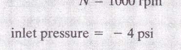
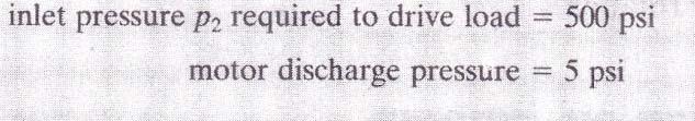
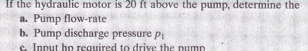
14 SPEED CONTROL OF A HYDRAULIC MOTOR Figure 9-19 shows a circuit where speed control of a hydraulic motor is accomplished using a pressure-compensated flow control valve. The operation is as follows: 1. In the spring-centered position of the tandem four-way valve, the motor is hydraulically locked. 2. When the four-way valve is actuated into the left envelope, the motor rotates in one direction. Its speed can be varied by adjusting the setting of the throttle of the flow control valve. In this way the speed can be infinitely it varied as the excess oil goes through the pressure relief valve. 3. When the four-way valve is deactivated, the motor stops suddenly and becomes locked. 4. When the right envelope of the four-way valve is in operation, the motor turns in the opposite direction. The pressure relief valve provides overload protection if, for example, the motor experiences an excessive torque load. 14
15 HYDRAULIC MOTOR BRAKING SYSTEM When using a hydraulic motor in a fluid power system, attention should sou be given gve to the tetypetype of loading that the motor will experience. A hydraulic motor may be driving a machine having a large inertia. This would create a flywheel effect on the motor, and stopping the flow of fluid to the motor would cause it to act as a pump. In a situation such as this, the circuit should be designed to provide fluid to the motor while it is pumping to prevent it from pulling in air. In addition, provisions should be made for the discharge fluid from the motor to be returned to the tank either unrestricted or through a relief valve. This would stop the motor rapidly but without damage to the system. Figure 9-20 shows a hydraulic motor braking circuit that possesses these desirable features for either direction of motor rotation. 15
16 HYDROSTATIC TRANSMISSION SYSTEM Figures 9-19 and 9-20 are actually hd hydrostatic transmissions. i They are called opencircuit drives because the pump draws its fluid from a reservoir. Its output is then directed to a hydraulic motor and discharged from the motor back into the reservoir. In a closed-circuit drive, exhaust oil from the motor is returned directly to the pump inlet. Figure 9-21 gives a circuit of a closed-circuit drive that allows for only one direction of motor rotation. The motor speed is varied by changing the pump displacement. The torque capacity of the motor can be adjusted by the pressure setting of the relief valve. Makeup oil to replenish leakage from the closed loop flows into the low-pressure side of the circuit through a line from the reservoir. 16
17 HYDROSTATIC TRANSMISSION SYSTEM Many hydrostatic transmissions are reversible closed-circuit drives that use a variable displacement reversible pump.this allows the motor to be driven in either direction and at infinitely variable speeds depending on the position of the pump displacement control. Figure 9-22 shows a circuit of such a system using a fixed displacement hydraulic motor. Internal leakage losses are made up by a replenishing pump, which keeps a positive pressure on the low-pressure side of the system. There are two check and two relief valves to accommodate the two directions of flow and motor rotation. 17


18 18

19 19
20 20
21 21


22 22
LECTURE 24 TO 26 - HYDRAULIC CIRCUIT DESIGN FREQUENTLY ASKED QUESTIONS
 LECUE 24 O 26 - HYDAULIC CICUI DESIGN EQUENLY ASKED QUESIONS 1. List three important considerations to be taken into account while designing a hydraulic circuit here are 3 important considerations in designing
2. Hydraulic Valves, Actuators and Accessories. 24 Marks
 2. Hydraulic Valves, Actuators and Accessories 24 Marks Co related to chapter 602.2 Describe working principle of various components used in hydraulic & pneumatic systems. 602.3 Choose valves, actuators
Hydrostatic Drive. 1. Main Pump. Hydrostatic Drive
 Hydrostatic Drive The Hydrostatic drive is used to drive a hydraulic motor at variable speed. A bi-directional, variable displacement pump controls the direction and speed of the hydraulic motor. This
Name common, basic subsystems that compose
 Chapter 13 Applying Hydraulic Power Typical Circuits and Systems 1 Objectives Name common, basic subsystems that compose complex hydraulic systems and describe their function. Compare the design and operation
INDIAN INSTITUTE OF TECHNOLOGY KHARAGPUR NPTEL ONLINE CERTIFICATION COURSE. On Industrial Automation and Control
 INDIAN INSTITUTE OF TECHNOLOGY KHARAGPUR NPTEL ONLINE CERTIFICATION COURSE On Industrial Automation and Control By Prof. S. Mukhopadhyay Department of Electrical Engineering IIT Kharagpur Topic Lecture
Lecture 25 HYDRAULIC CIRCUIT DESIGN AND ANALYSIS [CONTINUED]
![Lecture 25 HYDRAULIC CIRCUIT DESIGN AND ANALYSIS [CONTINUED]](/thumbs/92/110490177.jpg "Lecture 25 HYDRAULIC CIRCUIT DESIGN AND ANALYSIS [CONTINUED]") Lecture 5 HYDRAULIC CIRCUIT DESIGN AND ANALYSIS [CONTINUED] 1.1 Circuit for Fast Approach and Slow Die Closing A machine intended for high volume production has a high piston velocity. If not controlled,
Lecture 5 HYDRAULIC CIRCUIT DESIGN AND ANALYSIS [CONTINUED] 1.1 Circuit for Fast Approach and Slow Die Closing A machine intended for high volume production has a high piston velocity. If not controlled,
Input, Control and Processing elements
 PNEUMATIC & HYDRAULIC SYSTEMS CHAPTER FIVE Input, Control and Processing elements Dr. Ibrahim Naimi Valves The function of valves is to control the fluid path or the pressure or the flow rate. Depending
Module 6 Assignment Part A
 Module 6 Assignment Part A TOTAL MARKS Part A = 192 TOTAL QUESTIONS Part A = 36 Question 1 [3 Marks] What does pressure refer to in relation to hydrostatics and what is it dependent on? Question 2 [14
CH.4 Basic Components of Hydraulic and Pneumatic System/16 M HAP/17522/AE5G
 Content : 4.1 Hydraulic and Pneumatic actuators. 10 Marks Hydraulic Actuators - Hydraulic cylinders (single, double acting and telescopic) construction and working, Hydraulic motors (gear and piston type)
TUTORIAL QUESTIONS FOR COURSE TEP 4195
 TUTORIL QUESTIONS FOR COURSE TEP 4195 Data: Hydraulic Oil Density 870 kg/m 3 bsolute viscosity 0.03 Ns/m 2 Spool valve discharge coefficient 0.62. 1) hydrostatic transmission has a variable displacement
three different ways, so it is important to be aware of how flow is to be specified
 Flow-control valves Flow-control valves include simple s to sophisticated closed-loop electrohydraulic valves that automatically adjust to variations in pressure and temperature. The purpose of flow control
GPM Hydraulic Consulting, Inc. P.O. Box 689. Social Circle, GA Hydraulic Consulting, Inc
 Hydraulic Consulting, Inc This special promotional CD is to demonstrate how your hydraulic troubleshooting manual can be ordered as an Adobe Acrobat ebook. It can be installed on any computer with the
Track Drive Circuit - General System. Simplified Travel Circuit Diagrams: Neutral Controls Forward Travel Reverse Travel
 Section 7.1 Track Drive Circuit - General System Simplified Travel Circuit Diagrams: Neutral Controls... 7.1.2 Forward Travel... 7.1.4 Reverse Travel... 7.1.5 General... 7.1.3 Track Drive Circuit: General...
What does pressure refer to in relation to hydrostatics and what is it dependent on?
 Question 1 [3 Marks] What does pressure refer to in relation to hydrostatics and what is it dependent on? Question 2 [14 Marks] Make a circuit diagram of a regular hydraulic plant that is used to control
Test Which component has the highest Energy Density? A. Accumulator. B. Battery. C. Capacitor. D. Spring.
 Test 1 1. Which statement is True? A. Pneumatic systems are more suitable than hydraulic systems to drive powerful machines. B. Mechanical systems transfer energy for longer distances than hydraulic systems.
TUTORIAL QUESTIONS FOR THE INDUSTRIAL HYDRAULICS COURSE TEP 4205
 TUTORIAL QUESTIONS FOR THE INDUSTRIAL HYDRAULICS COURSE TEP 4205 The book for the course is Principles of Hydraulic System Design, by Peter J Chapple. Published by Coxmoor Publishing Co., UK. Available
Definitions of Technical Terms
 Definitions of Technical Terms ABSOLUTE A measure having as it s zero point of base the complete absence of the entity being measured. ABSOLUTE PRESSURE A pressure scale with zero point at a perfect vacuum.
Introduction. General Information. Systems Operation
 Systems Operation Introduction Reference: For illustrated Specifications, refer to the Specifications For 416, 426, 428, 436, 438, & Series II Backhoe Loaders Transmission, Form No. SENR3131. If the specifications
Denison GOLD CUP Product Catalog Piston Pumps & Motors For Open & Closed Circuits
 aerospace climate control electromechanical filtration fluid & gas handling hydraulics pneumatics process control sealing & shielding Denison GOLD CUP Product Catalog Piston Pumps & Motors For Open & Closed
Hydraulic Circuit Design
 26/10/05 Hydraulics & Pneumatics Hydraulic Circuit Design M. S. Sham Prasad Asst. Professor Dept. of I&P Engg. National Institute of Engg, Mysore Regenerative circuit : A Regenerative circuit is one in
LESSON 2 BASIC CONSTRUCTION AND OPERATION OF HYDRAULIC ACTUATING DEVICES, FLOW CONTROL, AND DIRECTIONAL DEVICES. STP Tasks:
 LESSON 2 BASIC CONSTRUCTION AND OPERATION OF HYDRAULIC ACTUATING DEVICES, FLOW CONTROL, AND DIRECTIONAL DEVICES STP Tasks: 552-758-1003 552-758-1071 OVERVIEW LESSON DESCRIPTION: In this lesson you will
Torque Converter, Transmission Pump, Screen And Filter
 Page 13 of 27 Transmission Hydraulic System In Forward (Engine Running - Type 2 & 3 Control Valve Shown) (4) Transmission control valve. (5) Neutralizer valve. (6) Neutralizer solenoid. (7) Flow control
Module 6. Actuators. Version 2 EE IIT, Kharagpur 1
 Module 6 ctuators Version 2 II, Kharagpur 1 Lesson 28 Industrial Hydraulic ircuits Version 2 II, Kharagpur 2 Lesson Objectives fter learning the lesson students should be able to escribe typical industrial
Appendix A. Standard Symbols for Hydraulic Components
 Table B.1 Flow lines Appendix A Standard Symbols for Components Continuous flow E Pilot connection L L>10E E Drain connection L L
Section 7.1. Wheel Drive Circuit - General System
 Section 7.1 Wheel Drive Circuit - General System Simplified Travel Circuit Diagrams: Neutral Controls... 7.1.2 Forward Travel... 7.1.4 Reverse Travel... 7.1.5 General... 7.1.3 Wheel Drive Circuit: General...
speed hydraulic motors. Permission granted to reproduce for educational use only. Contrast the operation of fixed- and variable-
 Chapter 9 Actuators Workhorses of the System 1 Objectives Describe the construction and operation of basic hydraulic cylinders, limited-rotation actuators, and motors. Compare the design and operation
Lecture 6. Systems review exercise To be posted this weekend Due next Friday (3/6)
") 150 Systems review exercise To be posted this weekend Due next Friday (3/6) Lecture 6 Coming week: Lab 13: Hydraulic Power Steering Lab 14: Integrated Lab (Hydraulic test bench) Topics today: Pumps and
150 Systems review exercise To be posted this weekend Due next Friday (3/6) Lecture 6 Coming week: Lab 13: Hydraulic Power Steering Lab 14: Integrated Lab (Hydraulic test bench) Topics today: Pumps and
SECTION II AIRPLANE AND SYSTEMS MODEL 750 HYDRAULIC
 HYDRAULIC The main hydraulic system is comprised of two independent systems; system A and system B. Hydraulic power is used to power the primary flight controls (rudder, elevators, ailerons, and roll spoilers),
Hydraulic Master Cylinders
 Hydraulic Master Cylinders flange mount and side mount, straight-bore and two-stage cylinders Hydraulic Cylinders for Mobile and Industrial Applications Why choose MICO? MICO, Incorporated designs, manufactures
LECTURE-23: Basic concept of Hydro-Static Transmission (HST) Systems
 Systems") MODULE-6 : HYDROSTATIC TRANSMISSION SYSTEMS LECTURE-23: Basic concept of Hydro-Static Transmission (HST) Systems 1. INTRODUCTION The need for large power transmissions in tight space and their control
MODULE-6 : HYDROSTATIC TRANSMISSION SYSTEMS LECTURE-23: Basic concept of Hydro-Static Transmission (HST) Systems 1. INTRODUCTION The need for large power transmissions in tight space and their control
Lesson 5: Directional Control Valves
 : Directional Control Valves Basic Hydraulic Systems Hydraulic Fluids Hydraulic Tank Hydraulic Pumps and Motors Pressure Control Valves Directional Control Valves Flow Control Valves Cylinders : Directional
PNEUMATIC CYLINDERS. Pneumatic Cylinders. Pneumatic Cylinders. Pneumatic Cylinders sometimes known as air cylinders are mechanical devices
 PNEUMATIC CYLINDERS Pneumatic Cylinders Pneumatic Cylinders Pneumatic Cylinders sometimes known as air cylinders are mechanical devices which use the power of compressed gas to produce a force in a reciprocating
ESCONDIDO FIRE DEPT TRAINING MANUAL Section DRIVER OPERATOR Page 1 of 13 Pumps and Accessory Equipment Revised
 DRIVER OPERATOR Page 1 of 13 PUMPS AND ACCESSORY EQUIPMENT Pumps are designed for many different purposes. In order to understand the proper application and operation of a pump in a given situation, firefighters
CLOSED CIRCUIT HYDROSTATIC TRANSMISSION
 Energy conservation and other advantages in Mobile Equipment Through CLOSED CIRCUIT HYDROSTATIC TRANSMISSION C. Ramakantha Murthy Technical Consultant Various features/advantages of HST Hydrostatic transmissions
Hydraulic Installation Guide
 Hydraulic Installation Guide Version 1.0 Hydraulic Installation Guide - Version 1.0 Change Log Date Change 03/11/2014 Initial Release ABT-TRAC 517-A Martin Avenue Rohnert Park, CA 94928 Tel: 707-586-3155
Pneumatic & Hydraulic SYSTEMS
 Pneumatic & Hydraulic SYSTEMS CHAPTER EIGHT HYDRAULIC PUMPS AND ACTUATORS Dr. Ibrahim Naimi The higher the discharge pressure, the lower the volumetric efficiency because internal leakage
Marine Engineering Exam Resource Review of Hydraulics
 1. What is Pascal s law? Pressure confined on a confined fluid will transmit the pressure in all directions and act with equal force on all areas at right angles. 2. How does the law pertain to hydraulics?
Hydraulic Maintenance & Troubleshooting. Content - Norman Kronowitz Presenter Jim Trinkle
 Hydraulic Maintenance & Troubleshooting Content - Norman Kronowitz Presenter Jim Trinkle Introduction Welcome to the CMA/Flodyne/Hydradyne s Hydraulic Troubleshooting presentation. We will introduce many
Daniel. Liquid Control Valves Technical Guide. Technical Guide DAN-LIQ-TG-44-rev0813. DAN-LIQ-TG-44-rev0208. February 2008.
 DAN-LIQ-TG-44-rev0208 February 2008 Daniel Liquid Control Valves Technical Guide www.daniel.com Daniel Measurement and Control Theory, Principle of Operation and Applications This brochure has been prepared
Lecture 7. Lab 14: Integrative lab (part 2) Lab 15: Intro. Electro-hydraulic Control Setups (2 sessions)
 Lab 15: Intro. Electro-hydraulic Control Setups (2 sessions)") Coming week s lab: Lecture 7 Lab 14: Integrative lab (part 2) Lab 15: Intro. Electro-hydraulic Control Setups (2 sessions) 4 th floor Shepherd (room # TBD) Guest lecturer next week (10/30/15): Dr. Denis
Coming week s lab: Lecture 7 Lab 14: Integrative lab (part 2) Lab 15: Intro. Electro-hydraulic Control Setups (2 sessions) 4 th floor Shepherd (room # TBD) Guest lecturer next week (10/30/15): Dr. Denis
Module 5: Valves. CDX Diesel Hydraulics. Terms and Definitions. Categories of Valves. Types of Pressure Control Valves
 Terms and Definitions Categories of Valves Types of Pressure Control Valves Types and Operation of Pressure Relief Valves Operation of an Unloading Valve Operation of a Sequencing Valve Operation of a
Lecture 6. Systems review exercise To be posted this afternoon Due in class (10/23/15)
") 153 Systems review exercise To be posted this afternoon Due in class (10/23/15) Lecture 6 Coming week: Lab 13: Hydraulic Power Steering Lab 14: Integrated Lab (Hydraulic test bench) Topics today: 2 min
153 Systems review exercise To be posted this afternoon Due in class (10/23/15) Lecture 6 Coming week: Lab 13: Hydraulic Power Steering Lab 14: Integrated Lab (Hydraulic test bench) Topics today: 2 min
Experiments on Hydraulic and Pneumatic circuit trainers HYDRAULIC CIRCUITS:
 Experiments on Hydraulic and Pneumatic circuit trainers HYDRAULIC CIRCUITS: Hydraulic circuits are used in high power and high load applications such as earth moving equipment. The pressure used in industrial
t2_ il PioC Oper. led Relet Valve Symbol ~~~ CHAPTER 12 Pilot Operated Pressure Control Valves
 CHAPTER 12 Pilot Operated Pressure Control Valves Unlike a simple or direct operated pressure control valve, where a spool is held biased by spring pressure only, a pilot operated valve has its spool biased
TPV Variable Displacement Closed Loop System Axial Piston Pump THE PRODUCTION LINE OF HANSA-TMP HT 16 / M / 852 / 0815 / E
 HYDRAULIC COMPONENTS HYDROSTATIC TRANSMISSIONS GEARBOXES - ACCESSORIES Certified Company ISO 9001-14001 ISO 9001 Via M. L. King, 6-41122 MODENA (ITALY) Tel: +39 059 415 711 Fax: +39 059 415 729 / 059 415
So how does a turbocharger get more air into the engine? Let us first look at the schematic below:
 How a Turbo System Works Engine power is proportional to the amount of air and fuel that can get into the cylinders. All things being equal, larger engines flow more air and as such will produce more power.
Basic Circuits. Brief Overview of Fluid Power. Pump Systems
 Basic Circuits Brief Overview of Fluid Power Chapter 1 (Material taken from Fluid Power Circuits and Controls, Cundiff, 2001) Most people have an intuitive concept of what at basic cylinder circuit or
Engine-specific faults and their remedy are given in the operating manual of the engine manufacturer. Fault Possible cause Rectification
 Simple troubleshooting D2-1.1 Engine Engine-specific faults and their remedy are given in the operating manual of the engine manufacturer. Fault Possible cause Rectification The superstructure cannot be
JIS symbols used in this catalog are old symbols following JISB0125-1: Refer to JISB0125-1: 2007 or JFPS2011: 2006 for new symbols.
 symbol s used in this catalog are old symbols following JISB0-: 00. Refer to JISB0-: 007 or JFPS0: 006 for new symbols. Page. Element of symbol. Line and port. Directional control valve. Pressure control
Hydraulic Power Supply and Motors Concept and Theory
 Hydraulic Power Supply and Motors Concept and Theory Graco, Inc. P.O. Box 1441 Minneapolis, MN 55440-1441 1996 Graco Inc. Form No. 321-046 1/96 Rev 2 SL Training 11/14 Hydraulic Systems Component Identification
LogSplitterPlans.Com
 Hydraulic Pump Basics LogSplitterPlans.Com Hydraulic Pump Purpose : Provide the Flow needed to transmit power from a prime mover to a hydraulic actuator. Hydraulic Pump Basics Types of Hydraulic Pumps
RELEASING PRESSURE IN THE HYDRAULIC SYSTEM,
 Testing And Adjusting Introduction NOTE: For Specifications with illustrations, make reference to SPECIFICATIONS for 225 EXCAVATOR HYDRAULIC SYSTEM, Form No. SENR7734. If the Specifications are not the
Contents. Quality Hydraulic Components from the Webtec Range. Introduction. Hydraulic Flow Control Valves
 Quality Hydraulic Components from the Webtec Range Contents Description Section Webtec Products Ltd Introduction 1 Hydraulic Flow Control Valves 2 Hydraulic Directional Control Valves and Check Valves
Spring Cylinder Rotary Actuator
 Spring Cylinder Rotary Actuator Rotary Actuator Spring Cylinder Rotary Actuators High torque and pneumatic stiffness combine together in the Mascot "Spring cylinder rotary actuator" These characteristics
SD Bendix DD-3 & SD-3 Safety Actuators PUSH PLATE & SHAFT ASSY. LOCKPORT SERVICE DIAPHRAGM SEPARATOR LOCKING PISTON O-RING LOCKING PISTON
 SD-02-4600 Bendix DD-3 & SD-3 Safety Actuators AUXILIARY DIAPHRAGM SERVICE DIAPHRAGM SEPARATOR PUSH PLATE & SHAFT ASSY. LOCKING PISTON O-RING LOCKING PISTON LOCKPORT DRAIN SLOT RETURN SPRING CAP O-RING
BETTIS ACTUATORS & CONTROLS HYDRAULIC CONTROL SYSTEM SPRING RETURN ACTUATORS
 BETTIS ACTUATORS & CONTROLS OPERATING INSTRUCTIONS M11S-S HYDRAULIC CONTROL SYSTEM FOR "G" SERIES SPRING RETURN ACTUATORS PART NUMBER: 121960 REVISION: "B" RELEASE DATE: July, 2006 Page 1 of 4 1.0 INTRODUCTION
Pilot Operated Directional Control Valves Series D1VP, D3DP, D4P, D9P, D11P
 Characteristics Series D1VP, D3DP, D4P, D9P, D11P The D1VP is a hydraulically controlled 4/3 or 4/ way directional control valve. The valve can be operated either by the pilot ports X and Y via the subplate
Design and Fabrication of Sequencing Circuit with Single Double Acting Cylinder
 Design and Fabrication of Sequencing Circuit with Single Double Acting Cylinder V.G.Vijaya Department of Mechatronics Engineering, Bharath University, Chennai 600073, India ABSTRACT: This project deals
VERTEX UNIVERSAL TESTING MACHINE
 OVERVIEW : Loading Accuracy as high as + 1% Straining at variable speeds to suit a wide range of materials. Continuous roll autographic recorder supplied as standard to enable study of the behavior of
Topic 1. Basics of Oil Hydraulic Systems
 Topic 1. Basics of Oil Hydraulic Systems Fluid power Fluid power is the technology that deals with the generation, control and transmission of forces and movement of mechanical element or system with the
United States Patent (19) Kubik
 Kubik") United States Patent (19) Kubik 11 Patent Number: ) Date of Patent: May, 1989 54 SELF-REGULATED HYDRAULIC CONTROL SYSTEM 76 Inventor: Philip A. Kubik, 27 Lochridge, Bloomfield Hills, Mich. 48013 21 Appl.
United States Patent (19) Kubik 11 Patent Number: ) Date of Patent: May, 1989 54 SELF-REGULATED HYDRAULIC CONTROL SYSTEM 76 Inventor: Philip A. Kubik, 27 Lochridge, Bloomfield Hills, Mich. 48013 21 Appl.
Axial piston variable pump A4VG Series 32. Europe. RE-E Edition: Replaces:
 Axial piston variable pump A4VG Series 32 Europe RE-E 92003 Edition: 04.2016 Replaces: 06.2012 High-pressure pump for applications in a closed circuit Size 28 to 125 Nominal pressure 400 bar Maximum pressure
Lecture 6. This week: Lab 13: Hydraulic Power Steering [ Lab 14: Integrated Lab (Hydraulic test bench) ]
![Lecture 6. This week: Lab 13: Hydraulic Power Steering [ Lab 14: Integrated Lab (Hydraulic test bench) ]](/thumbs/84/91055223.jpg "Lecture 6. This week: Lab 13: Hydraulic Power Steering [ Lab 14: Integrated Lab (Hydraulic test bench) ]") 133 Lecture 6 This week: Lab 13: Hydraulic Power Steering [ Lab 14: Integrated Lab (Hydraulic test bench) ] 4-way directional control valve; proportional valve; servo-valve Modeling / Analysis of a servo-valve
133 Lecture 6 This week: Lab 13: Hydraulic Power Steering [ Lab 14: Integrated Lab (Hydraulic test bench) ] 4-way directional control valve; proportional valve; servo-valve Modeling / Analysis of a servo-valve
MOREHOUSE INSTRUMENT COMPANY, INC. 60,000 LBS CAPACITY AIRCRAFT PART NUMBER SCALE S FORCE CALIBRATION PRESS PART NO.
 INDEX 1. GENERAL SPECIFICATION AND DRAWING 804000-03... 2 2. ASSEMBLY INSTRUCTIONS... 5 3. OPERATING INSTRUCTIONS... 6 4. MAINTENANCE INSTRUCTIONS... 7 5. CERTIFICATE OF CAPACITY LOAD TEST AND OVERLOAD...
Section 35 Chapter 2 HYDRAULIC SYSTEM HOW IT WORKS AND TROUBLESHOOTING NH
 Section 35 Chapter HYDRAULIC SYSTEM HOW IT WORKS AND TROUBLESHOOTING 6-80NH TABLE OF CONTENTS GENERAL INTRODUCTION... 35-3 Hydraulic Pumps... 35-3 Standard Flow PFC Pump Layout... 35-5 MegaFlow PFC Pump
ATM 322 PNEUMATICS MODULE 4
 ATM 322 PNEUMATICS MODULE 4 WARM UP VIDEO Explain the function of the one way flow control valve. Describe the main parts of the one way flow control valve. Adjust the one way flow control valve to the
 www.iranfluidpower.com آموزش هیدرولیک N A T I O N A L F L U I D P O W E R A S S O C I A T I O N FLUID POWER TRAINING Basic Hydraulics Course Introduction NFPA is pleased to present the Basic Hydraulics
Section 13 - E. 1 of 18. Engine Systems
 Engine Systems 1 of 18 ENGINE FUEL SYSTEM Introduction The fuel system uses electronic, hydraulic and mechanical functions to regulate the power and adapt it to the requirements at any one time. Air pressure
Task 4: Read the texts, look at the illustrations and do the activities below.
 Task 4: Read the texts, look at the illustrations and do the activities below. 4 BASIC OPERATIONS The Induction Stroke On the induction stroke, the inlet valve opens and the piston, moving down, creates
DENISON HYDRAULICS open loop pump controls series P140 A-mod, P260 B-mod service information
 DENISON HYDRAULICS open loop pump controls series P10 A-mod, P260 B-mod service information Publ. S1-AM02-A replaces S1-AM02 01-97 CONTENTS typical characteristics-------------------------------------------------------------------------------
350 Series Electrohydraulic Actuators
 March 2000 350 Series Electrohydraulic Actuators 350 Series electrohydraulic actuators (figure 1) use a dc milliampere signal to operate a variety of slidingstem or rotary valves for proportional or two-position
Click Here for Printable PDF File. CHAPTER 3 - BASIC INFORMATION for PERFORMING HYDRAULIC SYSTEM MAINTENANCE
 HWH Online Technical School Lesson 1: Introduction to Hydraulics Chapter 3 - "BASIC INFORMATION for PERFORMING HYDRAULIC SYSTEM MAINTENANCE" (Filename: ML57000-012-CH3.DOC Revised: 22APR16) Click Here
PNEUMATIC & HYDRAULIC SYSTEMS
 PNEUMATIC & HYDRAULIC SYSTEMS CHAPTER SIX PNEUMATIC SYSTEM DESIGN AND DEVELOPMENT Dr. Ibrahim Naimi Symbols And Standards In Pneumatics The development of pneumatic systems is assisted by a uniform approach
Aircraft Maintenance Prof. A.K Ghosh Prof. Vipul Mathur Department of Aerospace Engineering Indian Institute of Technology, Kanpur
 Aircraft Maintenance Prof. A.K Ghosh Prof. Vipul Mathur Department of Aerospace Engineering Indian Institute of Technology, Kanpur Lecture 05 Aircraft Landing Gear System Now, coming to the next aircraft
Turbo Tech 101 ( Basic )
") Turbo Tech 101 ( Basic ) How a Turbo System Works Engine power is proportional to the amount of air and fuel that can get into the cylinders. All things being equal, larger engines flow more air and as
Turbo Tech 101 ( Basic ) How a Turbo System Works Engine power is proportional to the amount of air and fuel that can get into the cylinders. All things being equal, larger engines flow more air and as
BMF TROUBLESHOOTING GUIDE
 BMF TROUBLESHOOTING GUIDE This document contains troubleshooting guidelines for PEP's standard BMF filters with pumps. REFERENCE DOCUMENTS: W-X-0039 BMF Electrical Wiring Drawing WP0011 BMF Control Panel
HMV Variable Motors Data and Specifications
 Data and Specifications Specifications HMR 55 HMR 75 HMR 105 HMR 135 cm 3/rev in 3/rev 55 3.36 75 4.57 105 6.40 135 8.23 Pressure Ratings Nominal 5000 PSIG Maximum 6090PSIG Peak 7250 PSIG Rated Speed 4000
Type 1051 and 1052 Size 33 Diaphragm Rotary Actuator
 Instruction Manual Type 1051 and 1052 Size 33 Diaphragm Rotary Actuator 1051 & 1052 Actuator Contents Introduction............................. 1 Scope of Manual........................... 1 Description................................
Tests & Adjustments - General Machine. General Safety Hydraulic Tank Turbo Boost Regulator
 Section 8.1 Tests & Adjustments - General Machine General Safety......................................... 8.1.2 Hydraulic Tank Turbo Boost Regulator........................ 8.1.2 Hydraulic Tank Safety
Pilot Operated Directional Control Valves Series D31DW, D41VW - D111VW
 Characteristics The D31, D41, D81, D91 and D111 are electrically controlled 4/3 or 4/ way directional control valves. The valves are pilot operated by an NG6 valve. Pressure and flow of the pilot oil have
Introduction. Pre-Lab
 The University Of Jordan School of Engineering Mechatronics Engineering Department Fluid Power Engineering Lab Experiments No.2 Pneumatic Control of a Double-acting Cylinder Objective: Students will be
Lecture 4. Lab this week: Review: Pilot-Open-Check. Cartridge valves Flow divider Properties of Hydraulic Fluids. Course feedback (2mins)
") 109 Lab this week: Lab 8 Sequencing circuit Lab 9 Flow divider Lecture 4 Review: Pilot-Open-Check Area ratio and pressure divider Cartridge valves Flow divider Properties of Hydraulic Fluids Viscosity
109 Lab this week: Lab 8 Sequencing circuit Lab 9 Flow divider Lecture 4 Review: Pilot-Open-Check Area ratio and pressure divider Cartridge valves Flow divider Properties of Hydraulic Fluids Viscosity
ENGINES ENGINE OPERATION
 ENGINES ENGINE OPERATION Because the most widely used piston engine is the four-stroke cycle type, it will be used as the example for this section, Engine Operation and as the basis for comparison in the
MF100BH (BASIC HYDRAULICS TRAINER) PARTS LIST CATALOG APRIL 2013
 PARTS LIST CATALOG APRIL 2013") MF100BH (BASIC HYDRAULICS TRAINER) PARTS LIST CATALOG APRIL 2013 MF100BH (BASIC HYDRAULICS TRAINER) PARTS LIST NOTE: Asterisk (*) in front of a part number indicates a component required to construct the
MF100BH (BASIC HYDRAULICS TRAINER) PARTS LIST CATALOG APRIL 2013 MF100BH (BASIC HYDRAULICS TRAINER) PARTS LIST NOTE: Asterisk (*) in front of a part number indicates a component required to construct the
Fluid Power System Model-Based Design. Energy Efficiency. Fluid Power System Model-Based Design Energy Efficiency. K. Craig 1
 Fluid Power System Model-Based Design Energy Efficiency K. Craig 1 Energy in Fluid Power Systems Fluid Power Systems have many advantages: High Power Density Responsiveness and Bandwidth of Operation High
Chapter 19. Applying Pneumatic Power. Typical Circuits and Systems
 Chapter 19 Applying Pneumatic Power Typical Circuits and Systems 1 Objectives Describe basic circuits that are frequently used to assemble complex pneumatic systems. Identify the placement and explain
Mark Twyman. Customer Support Regional Manager FMC Eaton. All rights reserved..
 787 EPAS Actuator Components, Function and Maintenance Mark Twyman Customer Support Regional Manager FMC Agenda EPAS Actuator Description EPAS Actuator Main components EPAS Actuator Normal operation EPAS
HYDRAULIC JACKS & TOOLS
 HYDRAULIC JACKS & TOOLS 323 Hydraulic jacks & tools Table of contents Page A characteristic of this force-oriented hydraulic Hydraulic cylinders, single-acting 328-337 program is the operating pressure
Variable Displacement Open Loop Circuit Axial Piston Pumps. V Series
 HYDRAULIC COMPONENTS HYDROSTATIC TRANSMISSIONS GEARBOXES - ACCESSORIES Via M. L. King, 6-41122 MODENA (ITALY) Tel: +39 59 415 711 Fax: +39 59 415 729 / 59 415 73 INTERNET: http://www.hansatmp.it E-MAIL:
Hydraulic Pumps Classification of Pumps
 Fluidsys Training Centre, Bangalore offers an extensive range of skill-based and industry-relevant courses in the field of Pneumatics and Hydraulics. For more details, please visit the website: https://fluidsys.org
TIP-200S-20 & TIP-200S-Ex-d-20 Power unit with electrohydraulic-acting spring-return rotary actuator (Normal & Explosion Proof Type)
") TIP-200S-20 & TIP-200S-Ex-d-20 Power unit with electrohydraulic-acting spring-return rotary actuator (Normal & Explosion Proof Type) Introduction Electrohydraulic-acting Spring-return rotary actuator 90
TIP-200S-20 & TIP-200S-Ex-d-20 Power unit with electrohydraulic-acting spring-return rotary actuator (Normal & Explosion Proof Type) Introduction Electrohydraulic-acting Spring-return rotary actuator 90
Series PVP Variable Volume Piston Pumps
 Series PVP Variable Volume Piston Pumps Catalog HY28-2661-CD/US zp2 hpm12-1.p65, lw, jk 1 Notes Series PVP hpm12-1.p65, lw, jk 2 Introduction Series PVP Series Sizes 6-14 Phased Out For Reference Only
Glossary. Visit Us Online: ABSOLUTE A measure having as its zero point or base the complete absence of the entity being measured.
 ABSOLUTE A measure having as its zero point or base the complete absence of the entity being measured. ABSOLUTE PRESSURE (psia) The pressure above absolute zero, the sum of atmospheric and gauge pressure.
DENISON HYDRAULICS Premier Series. open circuit pump controls P16 B-mod, P09 A-mod. service information
 DENISON HYDRAULICS Premier Series open circuit pump controls P6 B-mod, P0 A-mod service information Publ. S-AM06-A replaces S-AM06 Internet: http://www.denisonhydraulics.com E-mail: denison@denisonhydraulics.com
Axial piston variable motor A6VM Series 63. Europe. RE-E Edition: Replaces:
 xial piston variable motor 6V Series 63 Europe RE-E 91604 Edition: 05.2016 Replaces: 06.2012 ll-purpose high pressure motor Sizes 28: Nominal pressure 400 bar aximum pressure 450 bar Sizes 250 to 1000:
Considerations on Flow Regeneration Circuits and Hydraulic Motors Speed Variation at Constant Flow
 Considerations on Flow Regeneration Circuits and Hydraulic Motors Speed Variation at Constant Flow PhD. eng. Teodor Costinel POPESCU 1, Dipl. eng. lina Iolanda POPESCU 2, PhD. student eng. lexandru MRINESCU
HYDROMODEL-200. Implements and controls hydraulic and electro-hydraulic circuits. Transparent Hydraulics - Electro-hydraulics
 HYDROMODEL-200 Transparent Hydraulics - Electro-hydraulics Hydraulic and electro-hydraulic technology at a glance Implements and controls hydraulic and electro-hydraulic circuits www.smctraining.com training@smctraining.com
Troubleshooting, Service Tips, And Major Improvements For Hydrostatic Transmissions (Special Edition){3200}
{3200}") Page 1 of 75 Troubleshooting, Service Tips, And Major Improvements For Hydrostatic Transmissions (Special Edition){3200} 943, 953, 963, 973 Loaders Introduction The hydrostatic transmissions used in 943,
Page 1 of 75 Troubleshooting, Service Tips, And Major Improvements For Hydrostatic Transmissions (Special Edition){3200} 943, 953, 963, 973 Loaders Introduction The hydrostatic transmissions used in 943,
DESCRIPTION & OPERATION
 DESCRIPTION & OPERATION BRAKE BOOSTER Delco-Moraine Single Diaphragm A combined vacuum-hydraulic unit which uses a combination of intake manifold vacuum and atmospheric pressure to provide power assist.
Chapter 15. Inertia Forces in Reciprocating Parts
 Chapter 15 Inertia Forces in Reciprocating Parts 2 Approximate Analytical Method for Velocity & Acceleration of the Piston n = Ratio of length of ConRod to radius of crank = l/r 3 Approximate Analytical