Series 20 Axial Piston Pumps. Technical Information
|
|
|
- Dinah Little
- 5 years ago
- Views:
Transcription


1 Series 20 Axial Piston Pumps Technical Information
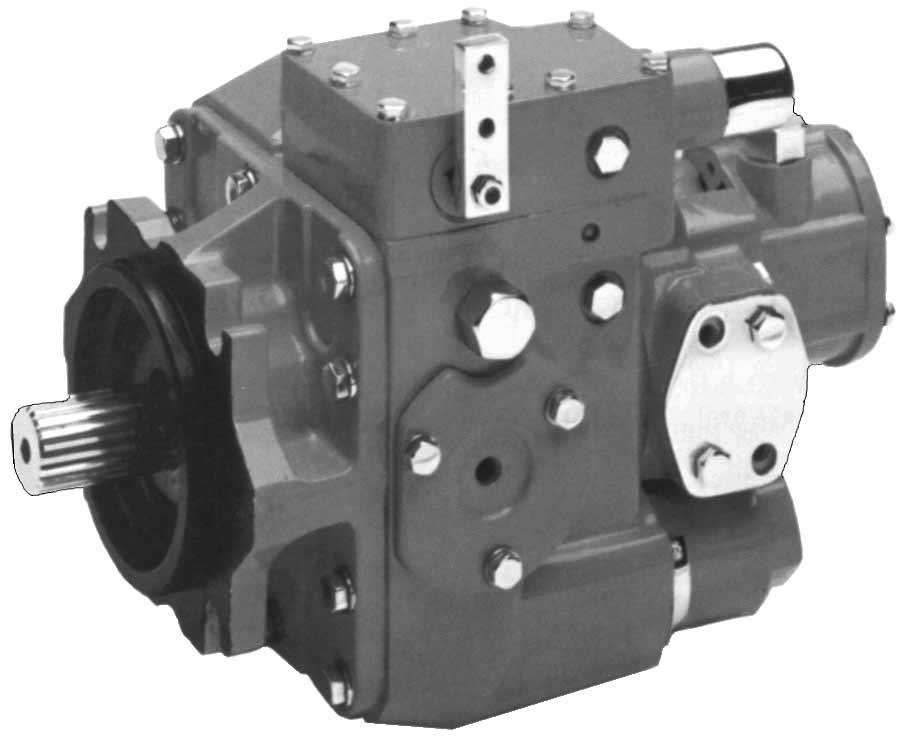
2 General Description INTRODUCTION Sauer-Danfoss a world leader in hydraulic power systems has developed a family of axial piston pumps. DESCRIPTION Sauer-Danfoss axial piston variable displacement pumps are of swash plate design with variable flow capability suitable for hydrostatic transmissions with closed loop circuit. Tilting the swash plate to the opposite side of the neutral or zero displacement position reverses flow direction. Sauer-Danfoss axial piston variable displacement pumps are well engineered and easy to handle. The full-length shaft with a highly efficient tapered roller bearing arrangement offers a high loading capacity for external radical forces. The hydro-mechanical servo displacement control maintains the selected swash plate position and hence pumps displacement. Upon release of the control handle, the swash plate automatically returns to zero position and the flow reduces to zero. High case pressures can be achieved without leakage even at the lowest temperatures by using suitable shaft seals. The servo valve arrangement offers the facility to incorporate function regulators and remote control systems. Axial piston units are designed for easy servicing. Complete dismantling and reassembly can be carried out with standard hand tools, and all components or sub-assemblies are replaceable. Axial piston variable displacement pumps of the Sauer-Danfoss pattern are made by licensed producers worldwide, providing consistent service and fully interchangeable parts. TYPICAL MARKETS Industrial Mining Transit Mixer Utility Vehicles , Sauer-Danfoss Sauer-Danfoss can accept no responsibility for possible errors in catalogues, brochures and other printed material. Sauer -Danfoss reserves the right to alter its products without prior notice. This also applies to products already ordered provided that such alterations can be made without subsequent changes being necessary in specifications already agreed. All trademarks in this material are properties of the respective companies. Sauer-Danfoss and the Sauer-Danfoss logotype are trademarks of the Sauer-Danfoss Group. All rights reserved. Front page: F , F , F , F DKMH.PN.315.A L0517
3 Contents CONTENTS General description... 2 Introduction... 2 Description... 2 Typical markets... 2 Sectional view... 4 Axial piston variable displacement pump... 4 System circuit description... 5 Pump and motor circuit description... 5 Pump circuit schematic... 5 Technical specification... 6 Technical parameters... 6 Design... 6 Type of mounting... 6 Pipe connections... 6 Direction of rotation... 6 Installation position... 6 External drain fluid loss... 6 Hydraulic parameters... 7 System pressure range, input p System pressure range, output p Case pressure... 7 Hydraulic fluid... 7 Hydraulic fluid temperature range... 7 Viscosity range... 7 Filtration... 7 Shaft load... 7 Technical data... 8 Determination of nominal pump size... 8 Servo displacement control... 9 Pump flow direction... 9 Reversing time Reset time Changing reversing and reset time Dimensions Frame size 033, 052, 070 and 089 cm Outline drawing, configuration PS, displacement control VML Tapered shaft end Pump configuration AA 010, displacement control VML Dimensions Frame size 119 cm Pump configuration PS, displacement control VML Dimensions Frame size 166 cm Pump configuration PS, displacement control VML Dimensions Frame size 227 cm Pump configuration PS, displacement control VML Dimensions Frame size 334 cm Pump configuration PS, displacement control VML Dimensions Frame size 119, 166, 227 and 334 cm Pump configuration AA 010, displacement control VML DKMH.PN.315.A L0517 3

4 Sectional View AXIAL PISTON VARIABLE DISPLACEMENT PUMP P E 4 DKMH.PN.315.A L0517
5 System Circuit Description PUMP AND MOTOR CIRCUIT DESCRIPTION HEAT EXCHANGER BYPASS VALVE RESERVOIR CONTROL HANDLE HEAT EXCHANGER VACUUM GAUGE REVERSIBLE VARIABLE DISPLACEMENT PUMP SERVO CONTROL CYLINDER PUMP SWASHPLATE SERVO PRESSURE RELIEF VALVES PURGE RELIEF VALVE FIXED DISPLACEMENT MOTOR CHARGE PRESSURE RELIEF VALVE INPUT SHAFT LOOP FLUSHING VALVE OUTPUT SHAFT SERVO CONTROL CYLINDER MOTOR SWASHPLATE WORKING LOOP (HIGH PRESSURE) WORKING LOOP (LOW PRESSURE) CONTROL FLUID SUCTION LINE CASE DRAIN FLUID P E Above figure shows schematically the function of a hydrostatic transmission using an axial piston variable displacement pump and a fixed displacement motor. PUMP CIRCUIT SCHEMATIC Servo M 1 A Designation: 1 = Variable displacement pump 2 = Charge pump 3 = Servo control valve 4 = Charge check valve 5 = Charge relief valve 6 = Filter 7 = Heat exchanger 7 L 2 S B L 1 Ports: A, B = Main pressure ports (working loop) S = Suction port - charge pump L1, L2 = Drain ports M = Gauge port - charge pressure P DKMH.PN.315.A L0517 5
6 Technical Specification TECHNICAL PARAMETERS Design Axial piston pump of swash plate design, with variable displacement. Type of mounting SAE four bolt flanges. Pipe connections Main pressure ports: SAE split flange Remaining ports: SAE O-ring boss Direction of rotation Clockwise or counterclockwise (viewing from the input shaft). Installation position Optional; pump housing must be always filled with hydraulic fluid. External drain fluid loss Typical values for 350 bar [5076 psi] and 18 swashplate angle (US gal/min) External drain fluid loss (l/min) Driveshaft speed n (min -1 ) (rpm) P E 6 DKMH.PN.315.A L0517
7 Technical Specification HYDRAULIC PARAMETERS System pressure range, input p 1 Variable displacement pump: Charge pressure nominal: 13 bar [189 psi] above case pressure Charge pressure minimum: 8 bar [116 psi], intermittent only Charge pump input pressure: Min. allowable pressure, continuous = 0.75 bar [10.9 psi] absolute Min. allowable pressure, intermittent = 0.50 bar [7.3 psi] absolute (for cold start) Charge pump output pressure: Max. operating pressure = 35 bar [508 psi] above case pressure System pressure range, output p 2 Pressure on port A or B: Max. operating pressure p = 420 bar [6092 psi] Max. high pressure setting p = 460 bar 1 [6672 psi] 1 only with POR-valve Case pressure Max. rated pressure = 2.5 bar [36.3 psi] Intermittent = 5.0 bar [72.5 psi] Hydraulic fluid Refer to Sauer-Danfoss publications Hydraulic Fluids and Lubricants and Experience with Bio Fluids for biodegradable hydraulic fluids. Hydraulic fluid temperature range ϑ min = - 40 C [- 40 F] ϑ max = 95 C [203 F] Viscosity range ν min = 7 mm 2 /s [49 SUS*] ν max = 1000 mm 2 /s [4630 SUS*] (intermittent cold start) Recommended viscosity range: mm 2 /s [ SUS*] *SUS (Saybolt Universal Second) Filtration Required cleanliness level: ISO Code 22/18/13 or better. Refer to Sauer-Danfoss publication Hydraulic Fluids and Lubricants and Design Guideline for Hydraulic Fluid Cleanliness. Shaft load The pump will accept radial and axial loads on its shaft, the maximum capacity being determined by direction and point of application of the load. Please contact your Sauer-Danfoss representative. DKMH.PN.315.A L0517 7
8 Technical Specification HYDRAULIC PARAMETERS (continued) Technical data Dimension Frame size Max. displacement cm [in 3 ] [2.03] [3.15] [4.26] [5.43] [7.24] [10.12] [13.87] [20.36] Charge pump displacement options cm 3 [0.75] [1.10] [1.15] [2.00] [4.00] [in 3 ] [1.10] [0.75] [2.00] [4.00] Minimum speed min -1 (rpm) 500 Rated speed 1 min -1 (rpm) Maximum swash plate angle degree ±18 Mass moment of inertia of rotating group kg m (without charge pump) [lbf ft ] [103.0] [193.2] [292.8] [421.7] [690.8] [1191.0] [2059.8] [3830.0] Weight kg [lb] [99] [121] [139] [172] [273] [362] [467] [595] 1 for higher speeds contact your Sauer Danfoss reprezentative Determination of nominal pump size Unit: Metric system: Inch system Pump V g n η v V g n η v output Q = l/min Q = [gpm] flow V g p V g p Input torque M = Nm M = [lbf in] 20 π η m 2 π η m V g n p V g n p Input power P = kw P = [hp] η t η t Efficiency characteristic curves available on request. V g = Pump displacement per revolution cm 3 [in 3 ] n = Pump speed min -1 (rpm) p = Hydraulic pressure differential bar [psi] η v = Pump volumetric efficiency η m = Pump mechanical efficiency η t = Pump total efficiency 8 DKMH.PN.315.A L0517
9 Technical Specification SERVO DISPLACEMENT CONTROL (LINEAR RESPONSE) Regulated by the control handle on the servo valve, the swash plate can be infinitely varied in both directions with the help of the servo system. The pump displacement resulting from any control handle position can be established using the figures on this page. The angle of the control handle for stroke initiation and for the final position of the stroke can vary from unit to unit within the range of the tolerance band. The inter-relation of flow direction, rotation of the pump and the control handle movement is shown below. Pump flow direction Flow direction changes with the direction of rotation and the control handle movement (see above). Maximum displacement C α D Null position α Maximum displacement Control handle Serrated shaft P E Pump rotation Counter-clockwise (L) Clockwise (R) Movement of control Pressure port Pressure port handle in direction OUT IN C B A D A B C A B D B A Vg [cm 3 ] Vg [cm 3 ] SPV 2/033 P Vg [cm 3 ] , SPV 2/ Vg [cm 3 ] 51.6 P Vg [cm 3 ] SPV 2/ Vg [cm 3 ] P Vg [cm 3 ] SPV 2/ Vg [cm 3 ] P DKMH.PN.315.A L0517 9
10 Technical Specification SERVO DISPLACEMENT CONTROL (LINEAR RESPONSE) (continued) Vg [cm 3 ] SPV 2/ Vg [cm 3 ] P Vg [cm 3 ] Vg [cm 3 ] P SPV 2/ Vg [cm 3 ] Vg [cm 3 ] P SPV 2/ Vg [cm 3 ] SPV 2/ Vg [cm 3 ] P Reversing time Time for the directional change of the flow from Q max, across zero to Q max, depending on the size of the control orifice fitted in the supply port to the servo valve (see below). The values given assume movement of the control handle directly from one end position to the other. Adjustment time of handle: < minimum reserving time Operating pressure: p 2 = 210 bar [3046 psi] Speed: n = 1450 min -1 (rpm) System temperature: 50 C [122 F] Viscosity: 35 mm 2 /s [164 SUS] Frame size Minimum reversing time (s) without orifice Maximum reversing time (s) with orifice 0.66 in supply port DKMH.PN.315.A L0517
11 Technical Specification SERVO DISPLACEMENT CONTROL (LINEAR RESPONSE) (continued) Orifices in the pilot ports Supply port with orifice Schematic diagram of servo valve with alternative orifice positions P E Reset time Time for reducing the flow from either flow direction from Q max to 0 releasing the control handle. Assuming no mechanical blockage of the control handle s free return and assuming no orifices in the pilot ports: Operating pressure: p 2 = 210 bar [3046 psi] System temperature: 50 C [122 F] Viscosity: 35 mm 2 /s [164 SUS] Frame size Minimum reset time (s) Pilot ports Orifice in supply port (see table on page 10) P E Servo valve counter bored recesses for orifice insert Changing reversing and reset time Inserting one orifice in each of the pilot ports can extend the reversing time. The reset time will also be extended. Inserting an orifice in one of the pilot ports only can extend the reversing time in one flow direction. The reset time will be extended only for this flow direction. DKMH.PN.315.A L
12 Dimensions Frame Size 033, 052, 070 and 089 cm 3 OUTLINE DRAWING, CONFIGURATION PS, DISPLACEMENT CONTROL VML 1 * Minimum and maximum angle α, (see section servo displacement control). ** Shaft spline data: spline shaft with involute spline, according to SAE handbook, 1963, class 1, fillet root side fit. C α * View D Null position α * 6.73 ± 0.1 Maximum displacement Maximum displacement Control handle R 25.4 R 50.8 Serrated shaft P E Port "L1": (use highest port as outlet) B M L K J Gauge port - servo cylinder pressure (both sides) 7/16-20 UNF-2B SAE straight thread O-ring boss Coupling may not protrude beyond 48 mm maximum lenght of full spline X Ø Ø N Ø O M H Charge pressure relief valve Clolcwise (R) rotation Counterclolcwise (L) rotation Port "S" Y ± 0.24 Shaft spline data:** Pitch Ø = P Pressure angle = 30 Number of teeth = R Pitch = S G F E D C A Approximate centre of gravity P E 12 DKMH.PN.315.A L0517
13 Dimensions Frame Size 033, 052, 070 and 089 cm 3 OUTLINE DRAWING, CONFIGURATION PS, DISPLACEMENT CONTROL VML 1 (continued) Gauge port - servo cylinder pressure Port "L 1 ": View Y U V Port "S": Suction port (charge pump) Position of charge pump for clockwise (R) rotation T W X Port "A" T Gauge port "M" Position of charge pump for counterclockwise (L) rotation Y Y Port "A" Port "L 2 ": U P E Max. torque for charge pump inlet port (7/8-14 UNF - 2B) is Nm [ lbf in]. Frame size Port A and B Port L 1 and L 2 Port S Port M 033 SAE flange, size 1 SAE split flange boss 7/8-14 UNF-2B 7/16-20 UNF-2B psi SAE straight thread SAE straight thread threads O-ring boss O-ring boss 3/8-16 UNC-2B deep DKMH.PN.315.A L
14 Dimensions Frame Size 033, 052, 070 and 089 cm 3 OUTLINE DRAWING, CONFIGURATION PS, DISPLACEMENT CONTROL VML 1 (continued) View X (for SPV 2/033-2/052 only) EE DD 9.4 ± 0.24 Control handle 1/4-20 UNC - 2A Control handle shaft spline data: 64/128 pitch, 64 diametral pitch acc. to SAE handbook 1963 Outside diameter = Number of teeth = 24 CC View X (for SPV 2/033-2/052 only) View X (for SPV 2/033-2/052 only) DD EE 9.4 ± 0.24 Control handle Control handle shaft spline data: 64/128 pitch, 64 diametral pitch acc. to SAE handbook 1963 Outside diameter = Number of teeth = 24 1/4-20 UNC - 2A EE DD GG 9.4 ± 0.24 Control handle Control handle shaft spline data: 64/128 pitch, 64 diametral pitch acc. to SAE handbook 1963 Outside diameter = Number of teeth = 24 1/4-20 UNC - 2A BB L Ø162 Rotation R CC BB FF GG 15 L Ø162 Rotation R 45 GG CC GG GG FF BB AA Rotation L Ø162 R 45 Approx. centre of gravity Ø JJ HH AA HH P E FF GG AA Approximate centre of gravity HH Ø JJ HH 216 Approximate centre of gravity HH Ø JJ HH P E 14 DKMH.PN.315.A L0517
15 Dimensions Frame Size 033, 052, 070 and 089 cm 3 OUTLINE DRAWING, CONFIGURATION PS, DISPLACEMENT CONTROL VML 1 (Continued) Dimensions Frame B mm C mm D mm E mm F mm G mm H mm mm J K mm L mm M mm N mm size [in] [in] [in] [in] [in] [in] [in] [in] [in] [in] [in] [in] [11.181] [10.354] [10.630] [8.858] [6.378] [6.260] [3.937] [3.701] [2.283] [1.890] [0.630] [3.307] [11.850] [11.024] [11.102] [9.685] [6.850] [5.984] [4.213] [4.173] [2.756] [1.890] [0.630] [3.307] [12.402] [11.575] [12.008] [10.197] [7.402] [5.748] [4.409] [4.724] [3.307] [1.890] [0.630] [3.307] [12.913] [12.087] [12.283] [10.669] [7.677] [5.512] [4.646] [5.079] [3.583] [1.929] [0.689] [3.858] Frame T mm U mm V mm W mm X mm Y mm mm AA mm BB mm CC mm DD mm EE mm size [in] [in] [in] [in] [in] [in] [in] [in] [in] [in] [in] [in] [2.441] [3.768] [3.622] [3.740] [2.008] [3.189] [0.118] [6.886] [5.906] [4.563] [4.724] [3.937] [2.677] [4.280] [4.016] [4.252] [2.094] [3.378] [0.250] [7.386] [6.378] [5.063] [5.157] [4.331] [2.811] [4.437] [4.134] [4.252] [2.382] [3.378] [0.374] [7.386] [6.378] [5.063] [5.236] [4.449] [3.059] [5.067] [4.528] [4.685] [2.559] [3.748] [0.500] [7.819] [6.811] [5.496] [5.669] [4.843] A 1 mm [in] Charge pump cm 3 Shaft spline Bore diameter for [in 3 ] shaft coupling Frame FF mm GG mm HH mm JJ mm O mm P mm R mm mm S size [in] [in] [in] [in] [0.732] [1.098] [in] [in] [in] [in] / [4.606] [[4.449] [4.252] [7.480] [13.425] [13.780] [ ] [1.313] [0.827] [ ] / [4.803] [4.567] [4.882] [7.520] [14.094] [14.449] [ ] [1.313] [0.827] [ ] / [4.961] [4.843] [5.118] [7.638] [14.646] [15.000] [ ] [1.313] [0.827] [ ] / [5.512] [5.276] [5.827] [7.638] [14.094] [15.512] [ ] [1.438] [0.906] [ ] 1 Short version available on request. Please contact your local Sauer-Danfoss representative. DKMH.PN.315.A L
16 Dimensions Frame Size 033, 052, 070 and 089 cm 3 TAPERED SHAFT END 32.5 ± 0.7 Key A x x max 22.4 ± 0.7 Depth, keygroove: 5,7 + 0,1 Shaft, cone: 1 : 8 Ø UNEF-2B Wrench size: 38 Coupling may not protrude beyond 81 mm maximum lenght of shaft Frame size = Ø84 Frame size 089 = Ø98 P E PUMP CONFIGURATION AA 010, DISPLACEMENT CONTROL VML 1 Servo 3 4 M 1 A Control and charge pressure port Designation: 1 = Variable Displacement pump 3 = Servo control valve 4 = Charge check valve 7 = Heat exchanger L 2 4 Return from charge relief valve to pump case B L 1 Ports: A, B = Main pressure ports (working loop) L1, L2 = Drain ports M = Gauge port - charge pressure 7 P E 16 DKMH.PN.315.A L0517
17 Dimensions Frame Size 033, 052, 070 and 089 cm 3 PUMP CONFIGURATION AA 010, DISPLACEMENT CONTROL VML 1 (continued) Control and charge pressure port R 3/ B A 2 Return from charge relief valve to pump case R 3/4 B A P E Dimensions Frame Size A mm [in] B mm [in] Weight kg [lb] [12.126] 285 [11.220] 46 [101] [12.756] 301 [11.850] 56 [123] [13.346] 316 [12.441] 63.5 [140] [13.858] 329 [12.953] 78.5 [173] DKMH.PN.315.A L
18 Dimensions Frame Size 119 cm 3 OUTLINE DRAWING, CONFIGURATION PS, DISPLACEMENT CONTROL VML 1 * Minimum and maximum angle α, (see section servo displacement control). ** Shaft spline data: spline shaft with involute spline, according to SAE handbook, 1963, class 1, fillet root side fit. Coupling may not protrude beyond 48 mm maximum lenght of full spline X Ø Ø 98 Ø M ± 0.24 Shaft spline data:** Pitch Ø = Pressure angle = 30 Number of teeth = 27 Pitch = 16/32 Internal opening for grooving = Gauge port - servo cylinder pressure Port "L1": View Y A 52.4 Port "L 1 ": (use highest port as outlet) Gauge port - servo cylinder pressure (both sides) 7/16-20 UNF-2B SAE straight thread O-ring boss 26.2 Approximate centre of gravity Position of charge pump for clockwise (R) rotation Charge pressure relief valve 2.12 Port "S": Charge pump suction port A [mm]: 498 for charging pump size for charging pump size 033 Charge pump pressure gauge port 7/16-20 UNF-2B SAE straight thread O - ring boss Port "A" Y 6.73 ± 0.1 Maximum displacement R 25.4 Serrated shaft View X Rotation L R Ø ± 0.24 Control handle 14 C 45 Null position * * 22.3 min. View Control handle shaft spline data: 64/128 pitch, 64 diametral pitch acc. to SAE handbook 1963 Outside diameter = Number of teeth = 24 1/4-20UNC - 2A D 22.3 min Maximum displacement Control handle R 50.8 Gauge port "M" Servo-cylinder with thread 1-5/16-12UN and with closing screw Port "A" Port "L 2 ": Position of charge pump for counterclockwise (L) rotation Approximate centre of gravity 14 Ø21.3 ± P E Frame size Port A and B Port L 1 and L 2 Port S Port M SAE flange, size 1 SAE split flange boss 7/8-14 UNF-2B 1 5/16-12 UNF-2B 7/16-20 UNF-2B psi SAE straight thread SAE straight thread SAE straight thread 4 threads O-ring boss O-ring boss O-ring boss 3/8-16 UNC-2B 18 deep 18 DKMH.PN.315.A L0517
19 Dimensions Frame Size 166 cm 3 OUTLINE DRAWING, CONFIGURATION PS, DISPLACEMENT CONTROL VML 1 * Minimum and maximum angle α, (see section servo displacement control). ** Shaft spline data: spline shaft with involute spline, according to SAE handbook, 1963, class 1, fillet root side fit. Coupling may not protrude beyond 48 mm maximum lenght of full spline X Ø Ø 98 Ø M Port "L1": (use highest port as outlet) Gauge port - servo cylinder pressure (both sides) 7/16-20 UNF-2B SAE straight thread O-ring boss 36.5 Charge pressure relief valve 2.12 Port "S": Charge pump suction port Y 6.73 ± 0.1 Maximum displacement R 25.4 C D Null position * * 25 min. View 25 min Maximum displacement Control handle R ± 0.24 Shaft spline data:** Pitch Ø = Pressure angle = 30 Number of teeth = 27 Pitch = 16/32 Internal opening for grooving = A Approximate centre of gravity A [mm]: 498 for charging pump size for charging pump size 033 Serrated shaft Gauge port - servo cylinder pressure Port "L1": View Y Position of charge pump for clockwise (R) rotation Charge pump pressure gauge port 7/16-20 UNF-2B SAE straight thread O - ring boss Port "A" View X ± 0.24 Control handle Rotation L R Control handle shaft spline data: 64/128 pitch, 64 diametral pitch acc. to SAE handbook 1963 Outside diameter = Number of teeth = 24 1/4-20UNC - 2A Gauge port "M" Servo-cylinder with thread 1-5/16-12UN and with closing screw Port "A" Port "L2": Position of charge pump for counterclockwise (L) rotation Approximate centre of gravity 16 Ø21.3 ± Ø P E Frame size Port A and B Port L 1 and L 2 Port S Port M SAE flange, size 1 1/2 SAE split flange boss 1 5/16-12 UNF-2B 1 5/16-12 UNF-2B 7/16-20 UNF-2B psi SAE straight thread SAE straight thread SAE straight thread 4 threads O-ring boss O-ring boss O-ring boss 5/8-11 UNC-2B 35 deep DKMH.PN.315.A L
20 Dimensions Frame Size 227 cm 3 OUTLINE DRAWING, CONFIGURATION PS, DISPLACEMENT CONTROL VML 1 * Minimum and maximum angle α, (see section servo displacement control). ** Shaft spline data: spline shaft with involute spline, according to SAE handbook, 1963, class 1, fillet root side fit. Coupling may not protrude beyond 48 mm maximum lenght of full spline X Ø Ø 98 Ø Ø Port "L1": (use highest port as outlet) Gauge port - servo cylinder pressure (both sides) 7/16-20 UNF-2B SAE straight thread O-ring boss 36.5 Charge pressure relief valve 2.12 Port "S": Charge pump suction port Y 6.73 ± 0.1 Maximum displacement R 25.4 C Null position * * 26.2 min. View D 26.2 min Maximum displacement Control handle R ± 0.24 Shaft spline data:** Pitch Ø = Pressure angle = 30 Number of teeth = 27 Pitch = 16/32 Internal opening for grooving = A Approximate centre of gravity A [mm]: 498 for charging pump size for charging pump size 033 Serrated shaft Gauge port - servo cylinder pressure Port "L1": View Y Position of charge pump for clockwise (R) rotation Charge pump pressure gauge port 7/16-20 UNF-2B SAE straight thread O - ring boss Port "A" View X ± 0.24 Control handle Rotation L R Control handle shaft spline data: 64/128 pitch, 64 diametral pitch acc. to SAE handbook 1963 Outside diameter = Number of teeth = 24 1/4-20UNC - 2A Gauge port "M" 100 Port "L2": Approximate centre of gravity 14.3 Ø21.3 ± 0.4 Ø Servo-cylinder with thread 1-5/16-12UN and with closing screw Port "A" Position of charge pump for counterclockwise (L) rotation P E Frame size Port A and B Port L 1 and L 2 Port S Port M SAE flange, size 1 1/2 SAE split flange boss 1 7/8-12 UNF-2B 1 5/16-12 UNF-2B 7/16-20 UNF-2B psi SAE straight thread SAE straight thread SAE straight thread 4 threads O-ring boss O-ring boss O-ring boss 5/8-14 UNC-2B 35 deep 20 DKMH.PN.315.A L0517
21 Dimensions Frame Size 334 cm 3 PUMP CONFIGURATION PS, DISPLACEMENT CONTROL VML 1 * Minimum and maximum angle α, (see section servo displacement control). ** Shaft spline data: spline shaft with involute spline, according to SAE handbook, 1963, class 1, fillet root side fit. C D Null position * * 26.7 min. View 26.7 min ± 0.1 Maximum displacement Maximum displacement Control handle R 25.4 R 50.8 Serrated shaft P E Port "L 1 ": (use highest port as outlet) Coupling may not protrude beyond 48 mm maximum lenght of full spline Gauge port - servo cylinder pressure (both sides) 7/16-20 UNF-2B SAE straight thread O-ring boss Charge pressure relief valve X Ø Ø 114 Ø M ± Port "S": Charge pump suction port Y Shaft spline data:** Pitch Ø = Pressure angle = 30 Number of teeth = 27 Pitch = 16/32 Internal opening for grooving = Approximate centre of gravity 656 P E DKMH.PN.315.A L
22 Dimensions Frame Size 334 cm 3 PUMP CONFIGURATION PS, DISPLACEMENT CONTROL VML 1 (continued) Gauge port - servo cylinder pressure Port "L1": View Y Position of charge pump for clockwise (R) rotation Charge pump pressure gauge port 7/16-20 UNF-2B SAE straight thread O - ring boss Port "A" L View X ± 0.24 Control handle Rotation 17.5 R 45 Control handle shaft spline data: 64/128 pitch, 64 diametral pitch acc. to SAE handbook 1963 Outside diameter = Number of teeth = 24 1/4-20UNC - 2A Gauge port "M" Ø Port "S" Port "A" Port "L2": Position of charge pump for counterclockwise (L) rotation Approximate centre of gravity Ø27.7 ± P E Frame size Port A and B Port L 1 and L 2 Port S Port M SAE flange, size 1 1/2 SAE flange, size 1 1/4 SAE split flange boss 1 7/8-12 UNF-2B SAE split flange boss 7/16-20 UNF-2B psi SAE straight thread 3000 psi SAE straight thread 4 threads O-ring boss 4 threads O-ring boss 5/8-11 UNC-2B 7/16-14 UNC-2B 35 deep 28 deep 22 DKMH.PN.315.A L0517
23 Dimensions Frame Size 119, 166, 227, 334 cm 3 PUMP CONFIGURATION AA 010, DISPLACEMENT CONTROL VML 1 Servo 7 L M 1 A Control and charge pressure port Return from charge relief valve to pump case B L 1 Designation: 1 = Variable Displacement pump 3 = Servo control valve 4 = Charge check valve 7 = Heat exchanger Ports: A, B = Main pressure ports (working loop) S = Suction port - charge pump L1, L2 = Drain ports M = Gauge port - charge pressure P E Return from charge relief valve to pump case R 3/4 73 B A C Control and charge pressure port R 3/ B A P E Dimensions Frame size A mm [in] B mm [in] C mm [in] Weight kg [lb] [16.614] 401 [15.787] [283] [18.740] 450 [17.717] 14 [0.551] 160 [353] [19.842] 478 [18.819] 208 [459] [21.496] 520 [20.472] 21 [0.827] [583] DKMH.PN.315.A L
24 OUR PRODUCTS Hydrostatic transmissions Hydraulic power steering Electric power steering Closed and open circuit axial piston pumps and motors Gear pumps and motors Bent axis motors Radial piston motors Orbital motors Transit mixer drives Planetary compact gears Proportional valves Sauer-Danfoss Hydraulic Power Systems Market Leaders Worldwide Sauer-Danfoss is a comprehensive supplier providing complete systems to the global mobile market. Sauer-Danfoss serves markets such as agriculture, construction, road building, material handling, municipal, forestry, turf care, and many others. We offer our customers optimum solutions for their needs and develop new products and systems in close cooperation and partnership with them. Sauer-Danfoss specializes in integrating a full range of system components to provide vehicle designers with the most advanced total system design. Sauer-Danfoss provides comprehensive worldwide service for its products through an extensive network of Authorized Service Centers strategically located in all parts of the world. Directional spool valves Cartridge valves Hydraulic integrated circuits Hydrostatic transaxles Integrated systems Fan drive systems Electrohydraulic controls Digital electronics and software Battery powered inverter Sensors Sauer-Danfoss (US) Company 2800 East 13th Street Ames, IA 50010, USA Phone: , Fax: Sauer-Danfoss (Neumünster) GmbH & Co. OHG Postfach 2460, D Neumünster Krokamp 35, D Neumünster, Germany Phone , Fax: Sauer-Danfoss (Nordborg) A/S DK-6430 Nordborg, Denmark Phone: , Fax: DKMH.PN.315.A L0517
Series 20 Axial Piston Pumps. Technical Information
 Series 20 Axial Piston Pumps Technical Information General Description INTRODUCTION Sauer-Danfoss a world leader in hydraulic power systems has developed a family of axial piston pumps. DESCRIPTION Sauer-Danfoss
Distribuíção, revenda emanutenção. CatálogosOnline. (11) (11)
 (11)") Distribuíção, revenda emanutenção CatálogosOnline (11)4174-3300-(11)4765-6775 www.hmc.com.br MAKING MODERN LIVING POSSIBLE Technical Information Axial Piston Pumps Series 20 powersolutions.danfoss.com
Distribuíção, revenda emanutenção CatálogosOnline (11)4174-3300-(11)4765-6775 www.hmc.com.br MAKING MODERN LIVING POSSIBLE Technical Information Axial Piston Pumps Series 20 powersolutions.danfoss.com
Series 20 Axial Piston Motors. Technical Information
 Series 20 xial Piston Motors Technical Information General Description INTRODUCTION Sauer-Danfoss a world leader in hydraulic power systems has developed a family of axial piston motors. DESCRIPTION Sauer-Danfoss
Series 20 Axial Piston Motors. Technical Information
 Series 20 xial Piston Motors Technical Information General Description INTRODUCTION Sauer-Danfoss a world leader in hydraulic power systems has developed a family of axial piston motors. DESCRIPTION Sauer-Danfoss
Series TMM Axial Piston Motor. Technical Information
 Series TMM Axial Piston Motor Technical Information General Description GENERAL DESCRIPTION These motors are designed primarily to be combined with other products in closed circuit systems to transfer
Technical Information Axial Piston Motors Series 20 powersolutions.danfoss.com
 MKING MODERN LIVING POSSILE Technical Information xial Piston Motors Series 20 powersolutions.danfoss.com General Information Introduction Danfoss a world leader in hydraulic power systems has developed
AXIAL PISTON PUMPS SHPV SECTIONAL VIEW
 AXIAL PISTON PUMPS SHPV SECTIONAL VIEW 2 SYSTEM CIRCUIT PUMP AND MOTOR CIRCUIT working loop (high pressure) working loop (low pressure) control fluid suction line case drain fluid Above figure shows schematically
AXIAL PISTON PUMPS AND MOTORS
 HPV-HMF SERIES SECTIONA VIEW AXIA PISTON VARIABE DISPACEMENT PUMP AXIA PISTON FIXED DISPACEMENT MOTOR Purge relief valve High pressure relief valves (adjustable) Cylinder block assembly Shaft seal Output
AXIAL PISTON PUMPS SHPV SECTIONAL VIEW
 AXIAL PISTON PUMPS SHPV SECTIONAL VIEW 2 AXIAL PISTON PUMPS SHPV SYSTEM CIRCUIT PUMP AND MOTOR CIRCUIT working loop (high pressure) working loop (low pressure) control fluid suction line case drain fluid
OMEW Standard and with Low Speed Option. Orbital Motors. Technical Information
 Standard and with Low Speed Option Orbital Motors Technical Information Contents Revision History Table of Revisions Date Page Changed Rev Jan 2009 Many major change BA Mar 2010 16 Japan location BB Contents
OML and OMM Orbital motors. Technical Information
 OML and OMM Orbital motors Technical Information OML and OMM A wide range of orbital motors F300030.TIF A WIDE RANGE OF ORBITAL MOTORS Sauer-Danfoss is a world leader within production of low speed orbital
Flow direction is reversed by tilting the swash plate to the opposite side of the neutral or zero displacement position.
 General Description Axial piston variable displacement pumps, Series 20, are of swash plates construction with variable flow capability suitable for hydrostatic transmission with closed loop circuit. The
AXIAL PISTON MOTORS SHMF
 SECTIONAL VIEW Purge relief valve High pressure relief valves (adjustable) Cylinder block assembly Shaft seal Output shaft Valve block Shuttle valve Swashplate 2 SYSTEM CIRCUIT PUMP AND MOTOR CIRCUIT working
Directional Control Valve Model Technical Information. Phased Out OUT BASE BKT CYL ROD
 BASE BKT CYL ROD OUT IN Directional Control Valve Model 1480 Technical Information History of Revisions Revisions Table of Revisions Date Page Changed Rev. May 2008 - first edition AA 2008 Sauer-Danfoss.
Technical Information Series 45 G Frame powersolutions.danfoss.com
 MAKING MODERN LIVING POSSIBLE Technical Information Series 45 G Frame powersolutions.danfoss.com Contents Frame G Design... 4 Specifications... 5 Performance G74B... 6 Performance G9C... 7 Order code...
Orbital Motors Type OMP, OMR and OMH. Technical Information
 Orbital Motors Type OMP, OMR and OMH Technical Information OMP, OMR and OMH A Wide Range of Hydraulics Motors F 301 245 A Wide Range of Hydraulic Motors Sauer-Danfoss is a world leader within production
OSPB, OSPC, OSPR, OSPD Open Center Steering units OSPB Closed Center Steering units TAD Torque amplifiers. Technical Information
 OSPB, OSPC, OSPR, OSPD Open Center Steering units OSPB Closed Center Steering units TAD Torque amplifiers Technical Information A wide range of steering components A WIDE RANGE OF STEERING COMPONENTS F300599
OMR Technical Information Versions
 Versions Versions Mounting flange Spigot diam,eter (front /rear end) Bolt circle diameter (BC) Shaft Port size European version US version Side port version End port version Flange port version Standard
PVG 120 Proportional Valves. Service Parts Manual
 PVG 120 Proportional Valves Service Parts Manual Contents and Data Survey CONTENTS AND DATA SURVEY Page Sectional drawing... 3 Identification...4 Installation PVG... 5 Spare parts... 22 Pos. 1: PVP, pump
Directional Control Valve
 Directional Control Valve Service and Parts Manual powersolutions.danfoss.com Directional Control Valves Service and Parts Manual: Contents SERVICE PARTS Inlet cover... 3-4 Outlet cover... 5-6 Standard
PVG 120 Proportional Valves. Specifications
 PVG 120 Proportional Valves s Ordering guidance and remote control units ORDERING GUIDANCE The module selection chart and the order form are both divided into fields. Each module has its own field: 0:
Series 90 Axial Piston Motors. Technical Information
 Series 90 Axial Piston Motors Technical Information HISTORY OF REVISIONS Table of Revisions Date Page Changed Rev. Fourth edition 2 520L0604 Contents GENERAL DESCRIPTION Cross section Cross section Cross
Series 40 M25 Axial Piston Pump. Service Parts Manual
 Series 40 M25 Axial Piston Pump Service Parts Manual 1996, 2004 Sauer-Danfoss. All rights reserved. Printed in U.S.A. Sauer-Danfoss accepts no responsibility for possible errors in catalogs, brochures
MAKING MODERN LIVING POSSIBLE. Technical Information. Orbital Motors TMVW. powersolutions.danfoss.com
 MAKING MODERN LIVING POSSIBLE Orbital Motors TMVW powersolutions.danfoss.com Revision history Table of revisions Date Changed Rev September 2015 New curve for permissible shaft load 0201 November 2014
Hydrostatic Steering Unit Type OSPB, OSPC and OSPF. Service Manual
 Hydrostatic Steering Unit Type OSPB, OSPC and OSPF Table of Contens Revision History Table of Revisions Date Page Changed Rev Dec 2008 26 Tightening torque changed BC Table of contens... 2 Exploded view
POWER SYSTEM MODE STATUS
 SX Generic Anti Spin Valve Control System System Description 7,7 POWER SYSTEM MODE STATUS 60, 8, 8, 0 9 0, 0, AMP Stecker AMP Connector 8 9 SX Generic Anti Spin Valve Control System Overview DESCRIPTION
Orbital Motors OMEW Standard and with Low Speed Option
 MAKING MODERN LIVING POSSIBLE Technical Information Orbital Motors OMEW Standard and with Low Speed Option powersolutions.danfoss.com Revision history Table of revisions Date Changed Rev October 2014 Changed
Technical Information Orbital Motors DH and DS powersolutions.danfoss.com
 MAKING MODERN LIVING POSSIBLE Technical Information Orbital Motors DH and DS powersolutions.danfoss.com and DS F 301 245 A Wide Range of Orbital Motors Danfoss Power Solutions is a world leader within
POWER SYSTEM MODE STATUS
 SX NFPE Control System System Description 4, 60,2 8, 8, 0 9 0 2, 0, AMP Stecker AMP Connector 4 28 29 42 Overview DESCRIPTION The Sauer-Danfoss NFPE (Non-Feedback Proportional Electric) System for Automotive
Orbital Motors DH and DS
 MAKING MODERN LIVING POSSIBLE Orbital Motors DH and DS powersolutions.danfoss.com Orbital Motors, DH and DS F 301 245 A Wide Range of Orbital Motors Danfoss Power Solutions is a world leader within production
T1P Transit Mixer Axial Piston Pump Size 069/089
 Technical Information T1P Transit Mixer Axial Piston Pump Size 069/089 powersolutions.danfoss.com Revision history Table of revisions Date Changed Rev May 2016 Updated to Engineering Tomorrow design. 0201
DH Technical Information. Versions. Versions
 Versions Versions Mounting flange Shaft Port size European version US version Side port version End port version Flange port version Standard shaft seal High pressure shaft seal Drain connection Check
H1 Axial Piston Pump Size 147/165, Single. Technical Information
 H1 Axial Piston Pump Size 147/165, Single Technical Information Revisions Revision History Table of revisions Date Page Changed Rev 30 Jul, 2009 First edition AA Jul, 2010 4-6, 10, 12-13 New EC directive
Steering Priority Valve OLS 160
 MAKING MODERN LIVING POSSIBLE Service Manual Steering Priority Valve OLS 160 powersolutions.danfoss.com Revision History Table of Revisions Date Changed Rev Mar 2014 Converted to Danfoss layout - DITA
Axial piston variable pump A4VG Series 32. Europe. RE-E Edition: Replaces:
 Axial piston variable pump A4VG Series 32 Europe RE-E 92003 Edition: 04.2016 Replaces: 06.2012 High-pressure pump for applications in a closed circuit Size 28 to 125 Nominal pressure 400 bar Maximum pressure
Series cc Axial Piston Motor. Parts Manual
 Series 90 130 cc Axial Piston Motor 2007 Sauer-Danfoss. All rights reserved. Sauer-Danfoss accepts no responsibility for possible errors in catalogs, brochures and other printed material. Sauer-Danfoss
TMVW Orbital Motors. Technical Information
 Orbital Motors Technical Information A Wide Range of Orbital Motors A Wide Range of Orbital Motors F300030 Tif Sauer-Danfoss is a world leader within production of low speed orbital motors with high torque.
OMT Series 2. Orbital Motors. Service Manual
 OMT Series 2 Orbital Motors Table of Contens, Special Versions Revision History Table of Revisions Date Page Changed Rev Sept 2003 CA Feb 200 4-5 Drain plug updated, Layout adjusted CB Sep 200 6 New back
Orbital Motors OMS, OMT and OMV Orbital Motors
 MAKING MODERN LIVING POSSIBLE Technical Information Orbital Motors OMS, OMT and OMV Orbital Motors powersolutions.danfoss.com Revision history Table of revisions Date Changed Rev November 2014 Converted
Group 1 Gear Pumps Technical Information General Information
 General Information OVERVIEW The Sauer-Danfoss Group is a range of peak performance fixed-displacement gear pumps. Constructed of a high-strength extruded aluminum body with aluminum cover and flange,
Axial Piston Variable Pump AA4VG
 Electric Drives and Controls Hydraulics Linear Motion and Assembly Technologies Pneumatics Service Axial Piston Variable Pump AA4VG RA 92003-A/06.09 1/64 Replaces: 03.09 Data sheet Series 32 Size 28...
Quick Reference Parts Manual Variable Displacement Motor Series 20, series powersolutions.danfoss.com
 MAKING MODERN LIVING POSSIBLE Quick Reference Parts Manual Variable Displacement Motor Series 20, 20-27 series powersolutions.danfoss.com 2 Contents Service parts Exploded view drawing (20 thru 23 series)...4
RE 91808/ AA4VSE Plug-in dual displacement motor. High pressure range. Series 10 Axial piston swashplate design, SAE model
 AA4VSE Plug-in dual displacement motor Series Axial piston swashplate design, SAE model RE 91808/09.90 RE 91808/09.90 Brueninghaus Hydromatik Size 250 Nominal pressure 350 bar Peak pressure 400 bar High
Technical Information Series 45 H Frame powersolutions.danfoss.com
 MAKING MODERN LIVING POILE Technical Information eries 45 H Frame powersolutions.danfoss.com Contents Frame H Design... 4 pecifications... 5 Performance H57... 6 Performance H75D... 7 Order code... 8 Controls...
AXIAL PISTON MOTORS MF S E R I E S 2 0 C L O S E D C I R C U I T
 AXIAL PISTON MOTORS MF GENERAL DESCRIPTION Axial piston fixed displacement motors, Series 20, are of swash plate construction with preset displacement, and are intendent for closed circuit operation. The
L and K Frame Variable Motors. Technical Information
 L and K Frame Variable Motors Technical Information Revisions Revisions Table of Revisions Date Page Changed Rev. April 2008 6 corrected the schematic drawings BE January 2008 17 removed displacement limiter
Fixed Displacement Motor AA2FM (A2FM)
") Fixed Displacement Motor 2FM (2FM) Series 6, for Open and Closed Circuits xial Piston, ent xis Design 5800 psi 6500 psi rueninghaus Hydromatik Sizes 5 1000 Nominal Pressure up to Peak Pressure up to (400
Fixed Displacement Motor 2FM (2FM) Series 6, for Open and Closed Circuits xial Piston, ent xis Design 5800 psi 6500 psi rueninghaus Hydromatik Sizes 5 1000 Nominal Pressure up to Peak Pressure up to (400
Hydraulic Motor/Pump. Series F11/F12 Fixed Displacement. parker.com/pmde
 Hydraulic Motor/Pump Series F11/F12 Fixed Displacement parker.com/pmde Series F11/F12 Torque (M) M = D x p x η hm 63 [Nm] Conversion factors 1 kg... 2.20 lb 1 N... 0.225 lbf 1 Nm... 0.738 lbf ft 1 bar...14.5
S5X Shift On The Go (SOTG) Control System. System Description 223,5 82,25 77,75 8,5 8,5 164,5 10,3. AMP Stecker AMP Connector 52,5 POWER SYSTEM MODE
 Control System. System Description 223,5 82,25 77,75 8,5 8,5 164,5 10,3. AMP Stecker AMP Connector 52,5 POWER SYSTEM MODE") SX Shift On The Go (SOTG) Control System System escription 47, POWER SYSTEM 8, 77,7 8, MOE STTUS 8, 0 0 64, 0, MP Stecker MP Connector 4 6 8 4 8, SX Shift On The Go (SOTG) Control System Overview ESCRIPTION
SX Shift On The Go (SOTG) Control System System escription 47, POWER SYSTEM 8, 77,7 8, MOE STTUS 8, 0 0 64, 0, MP Stecker MP Connector 4 6 8 4 8, SX Shift On The Go (SOTG) Control System Overview ESCRIPTION
Axial piston variable pump A10V(S)O Series 31. Americas. RE-A Edition: Replaces:
O Series 31. Americas. RE-A Edition: Replaces:") Axial piston variable pump A10V()O eries 31 Americas RE-A 92701 Edition: 02.2017 Replaces: 03.2012 ize 18 (A10VO) izes 28 to 140 (A10VO) Nominal pressure 4100 psi (280 bar) Maximum pressure 5100 psi (350
Axial piston variable pump A10V()O eries 31 Americas RE-A 92701 Edition: 02.2017 Replaces: 03.2012 ize 18 (A10VO) izes 28 to 140 (A10VO) Nominal pressure 4100 psi (280 bar) Maximum pressure 5100 psi (350
Series 40 MMF044D and MMV044D Axial Piston Motors. Parts Manual
 Series 40 MMF044D and MMV044D Axial Piston Motors 2003, 2008 Sauer-Danfoss. All rights reserved. 2 520L586 Rev AA January 2008 Sauer-Danfoss accepts no responsibility for possible errors in catalogs, brochures
Variable Displacement Pump A4VG for closed circuits
 RE 92 003/05.99 RE 92 003/05.99 replaces: 02.98 Variable Displacement Pump A4VG for closed circuits Sizes 28...250 Series 3 Nominal pressure 400 bar Peak pressure 450 bar A4VG...EP Index Features 1 Ordering
Series 40 MMF035D and MMV035D Axial Piston Motors. Parts Manual
 Series 40 MMF035D and MMV035D Axial Piston Motors 2003, 2008 Sauer-Danfoss. All rights reserved. 2 520L0602 Rev AA January 2008 Sauer-Danfoss accepts no responsibility for possible errors in catalogs,
Series T90 Transit Mixer Drive System
 MAKING MODERN LIVING POSSIBLE Technical Information Series T90 Transit Mixer Drive System powersolutions.danfoss.com Contents Series T90 Transit Mixer Drive Transit Mixer Pump Series T90 General Description...
Axial piston fixed motor A2FM series 70. Americas. RE-A Edition:
 Axial piston fixed motor A2FM series 70 Americas RE-A 91071 Edition: 05.2015 A2FMN (Sizes 90 and 107): Nominal pressure 300 bar Maximum pressure 350 bar A2FMM (Sizes 80 and 90): Nominal pressure 400 bar
Hydraulic Motor/Pump. Series F11/F12 Fixed Displacement. parker.com/pmde
 Hydraulic Motor/Pump Series F11/F12 Fixed Displacement parker.com/pmde Series F11/F12 Torque (M) M = D x p x η hm 63 [Nm] Conversion factors 1 kg... 2.20 lb 1 N... 0.225 lbf 1 Nm... 0.738 lbf ft 1 bar...14.5
Transit Mixer Axial Piston Motor Size 070/084/089
 Technical Information Transit Mixer Axial Piston Motor Size 070/084/089 powersolutions.danfoss.com Revision history Table of revisions Date Changed Rev June 2017 Update to Engineering Tomorrow 0202 Mar
OMR, OMR C, and OMRW N Series 5 and 6. Repair Instructions
 , C, and W N Series and Orbital Motors, C and W N Series and Table of Contents Revision View Safety Precautions Date Page Changed Revision 29 Jun, 200 all Changed from Danfoss to Sauer Danfoss lay out
Proportional Valve Group PVG 120
 MAKING MODERN LIVING POSSIBLE Specification Proportional Valve Group PVG 120 powersolutions.danfoss.com Revision history Table of revisions Date Changed Rev May 2014 Converted to Danfoss layout DITA CMS
Axial piston variable pump A10V(S)O Series 31
O Series 31") Axial piston variable pump A10V()O eries 31 RE 92701 Edition: 06.2016 Replaces: 01.2012 ize 18 (A10VO) izes 28 to 1 (A10VO) Nominal pressure 280 bar Maximum pressure 350 bar Open circuit Features Variable
Axial piston variable pump A10V()O eries 31 RE 92701 Edition: 06.2016 Replaces: 01.2012 ize 18 (A10VO) izes 28 to 1 (A10VO) Nominal pressure 280 bar Maximum pressure 350 bar Open circuit Features Variable
Medium Duty Piston Pump Variable Displacement Closed Circuit
 Medium Duty Piston Pump Variable Displacement Closed Circuit Model 70160 Model 70360 Model 72400 20.3 cm 3 /r [1.24 in 3 /r] 40.6 cm 3 /r [2.48 in 3 /r] 40.6 cm 3 /r [2.48 in 3 /r] 23.6 cm 3 /r [1.44 in
Closed Circuit Axial Piston Pumps H1 115/130 cc
 MAKING MODERN LIVING POSSIBLE Conversion Manual Closed Circuit Axial Piston Pumps H1 115/130 cc powersolutions.danfoss.com Revision history Table of revisions Date Changed Rev December 2015 First edition
P90 VARIABLE DISPLACEMENT PUMP T E C H N I C A L C A T A L O G
 P90 VARIABLE DISPLACEMENT PUMP T E C H N I C A L C A T A L O G Variable displacement pump POCLAIN HYDRAULICS Design Slider block Swashplate hold-down Servo piston Servo arm Piston Slipper Displacement
Hydraulic Motor/Pump. Series F11/F12 Fixed Displacement
 Hydraulic Motor/Pump Series F11/F12 Fixed Displacement Series F11/F12 Torque (M) M = D x p x η hm 63 [Nm] Conversion factors 1 kg... 2.20 lb 1 N... 0.225 lbf 1 Nm... 0.738 lbf ft 1 bar...14.5 psi 1 l...0.264
US version. Drain connection
 Versions OMT Versions Mounting flange Standard flange Shaft Port size Europea n version US version Drain connection Check valve Low pressure release High pressure release Cyl. 4 mm G 3/4 X Yes Yes OMT
Genuine Metaris MA10VO/VSO Technical Catalog. Variable Displacement Piston Pump - A10V Series 31 & 52
 Genuine Metaris MA10VO/VSO Technical Catalog www.metaris.com Contents General Series MA10VO/VSO Series 31 4 Page Features 4 Technical Data 5 Performance Information 6 Model Code Breakdown 9 Fluid Info
Hydraulic Motor/Pump. Series F11/F12 Fixed Displacement. parker.com/pmde
 Hydraulic Motor/Pump Series F11/F12 Fixed Displacement parker.com/pmde Series F11/F12 Torque (M) M = D x p x η hm 63 [Nm] Conversion factors 1 kg... 2.20 lb 1 N... 0.225 lbf 1 Nm... 0.738 lbf ft 1 bar...14.5
MCX106A Hall Effect Level Sensor. Technical Information
 MCX106A Hall Effect Level Sensor Technical Information Revisions Revision History Table of Revisions Date Page Changed Rev 21 Jan, 2011 Initial release AA 2011 Sauer-Danfoss. All rights reserved. 2 Sauer-Danfoss
OMH. Repair Instructions
 OMH Table of Contents Revision View Date Page Changed Revision Jun 2006 New AA Apr 200 6 Japan location AB Sep 200 6 New back cover AC Safety Precautions Always consider safety precautions before beginning
Parts Manual Closed Circuit Axial Piston Pump DDC20 powersolutions.danfoss.com
 MAKING MODERN LIVING POSSIBLE Parts Manual Closed Circuit Axial Piston Pump DDC20 powersolutions.danfoss.com 2 Contents General Information Variable pump & fixed motor Service parts identification...4
Fixed Displacement Pump A4FO Series 10 Axial Piston Unit, Swashplate Design
 Fixed Displacement Pump A4FO Series 10 Axial Piston Unit, Swashplate Design Sizes 71 0 Nominal pressure 3 bar Peak pressure 400 bar RE 91455/01.94 RE 91455/01.94 Replaces 07.88 Other fixed displacement
Closed Circuit Axial Piston Pump DDC20
 Parts Manual Closed Circuit Axial Piston Pump powersolutions.danfoss.com Revision history Table of revisions Date Changed Rev July 2017 Updated to Engineering Tomorrow design 0302 2 Danfoss July 2017 AX00000134en-US0302
OMP, OMP C, OMPW, and OMPW N Series 7 and 8. Repair Instructions
 , C, W, and W N Series and 8 Orbital Motors, C, and W/N Series and 8 Table of Contents Revision View Safety Precautions Date Page Changed Revision 29 Jun, 200 all Changed from Danfoss to Sauer Danfoss
Axial Piston Fixed Pump A17FNO Series 10
 Axial Piston Fixed Pump A17FNO Series 10 RE 91510 Issue: 06.2012 Replaces: 03.2010 Size 125 Nominal pressure 250 bar Maximum pressure 300 bar For commercial vehicles Open circuit Features Fixed pump with
Axial piston variable pump A4VG Series 40
 Axial piston variable pump A4VG eries 40 RE 92004 Edition: 07.2016 Replaces: 06.2012 High-pressure pump for applications in a closed circuit up to 500 bar ize 110...280 Nominal pressure 450 bar Maximum
Axial Piston Fixed Motor A2FM
 Axial Piston Fixed Motor A2FM RE 91001/06.2012 1/46 Replaces: 09.07 Data sheet Series 6 Size Nominal pressure/maximum pressure 5 315/350 bar 10 to 200 400/450 bar 250 to 1000 350/400 bar Open and closed
Steering Unit Type OSPB and OSPC Type ON and CN
 MAKING MODERN LIVING POSSIBLE Service Manual Steering Unit Type OSPB and OSPC Type ON and CN powersolutions.danfoss.com Revision History Table of Revisions Date Changed Rev Mar 2014 Converted to Danfoss
Hydraulic Motor/Pump Series F11/F12 zp12
 Hydraulic Motor/Pump zp12 Fixed Displacement zp11 Catalogue HY17-8249/US March 2004 Conversion factors 1 kg... 2.20 lb 1 N... 0.225 lbf 1 Nm... 0.738 lbf ft 1 bar...14.5 psi 1 l...0.264 US gallon 1 cm
OSPB, OSPC, OSPF, OSPD, OSPQ, OSPL Load Sensing Steering Units. OLS Priority Valves. OSQ Flow Amplifiers. Technical Information
 OSPB, OSPC, OSPF, OSPD, OSPQ, OSPL Load Sensing Steering Units OLS Priority Valves OSQ Flow Amplifiers Technical Information A Wide Range of Steering Components Revision History Table of Revisions Date
Series cc Axial Piston Motor. Parts Manual
 Series 90 100 cc Axial Piston Motor 2007 Sauer-Danfoss. All rights reserved. Sauer-Danfoss accepts no responsibility for possible errors in catalogs, brochures and other printed material. Sauer-Danfoss
H1 Pump Filter Bypass Sensor
 MAKING MODERN LIVING POSSIBLE Electrical Installation H1 Pump Filter Bypass Sensor powersolutions.danfoss.com Revision history Table of revisions Date Changed Rev September 2015 Minor layout revision BC
Series ASC Anti Spin Control Valve
 MAKING MODERN LIVING POSSIBLE Technical Information Series ASC Anti Spin Control Valve powersolutions.danfoss.com Revision history Table of revisions Date Changed Rev March 2014 Converted to Danfoss layout
Axial piston variable motor A6VM series 71
 xial piston variable motor 6VM series 71 RE 91610 Edition: 06.2014 Replaces: 04.2013 Sizes 60 to 215 Nominal pressure 450 bar Maximum pressure 500 bar Open and closed circuits Features Variable motor with
TPV Variable Displacement Closed Loop System Axial Piston Pump HY-TRANS THE PRODUCTION LINE OF HANSA-TMP HT 16 / M / 501 / 1009 / E
 HYDRAULIC COMPONENTS HYDROSTATIC TRANSMISSIONS GEARBOXES - ACCESSORIES HY-TRANS THE PRODUCTION LINE OF HANSA-TMP Via M. L. King, 6-41122 MODENA (ITALY) Tel: +39 059 415 711 Fax: +39 059 415 729 / 059 415
Series 45 Open Circuit Axial Piston Pumps. Technical Information. Displacement Piston. Swashplate. Piston. Tapered Roller Bearing
 Series 45 Open Circuit Axial Piston Pumps Technical Information Displacement Piston Piston Swashplate Tapered Roller earing Tapered Roller earing Valve Plate Cylinder lock Kit Shaft Seal General Description
Axial piston variable pump A10VO Series 32
 Axial piston variable pump A10VO eries 32 RE 92705 Edition: 06.2016 Replaces: 01.2012 Optimized medium pressure pump for powerful machines izes 45 to 180 Nominal pressure 280 bar Maximum pressure 350 bar
Catalog HY /NA. Catalog HY /NA. Parker Hannifin Corporation Hydraulic Pump Division Marysville, Ohio USA
 Catalog HY28-6/NA PV, PVT Series Piston Pumps Variable Volume Catalog HY28-6/NA 1 Catalog HY28-6/NA Notes Series PV 2 Catalog HY28-6/NA Introduction Series PV Quick Reference Data Chart Pump Delivery Approx.
Steering Valve EHPS and EHPS with OLS 320
 Service Manual Steering Valve EHPS and EHPS with OLS 320 powersolutions.danfoss.com Revision history Table of revisions Date Changed Rev July 2016 Updated EHPS spare parts list 0102 June 2015 First version
H1 Axial Piston Pump Size 147/165, Single
 MAKING MODERN LIVING POSSIBLE Technical Information H1 Axial Piston Pump Size 147/165, Single powersolutions.danfoss.com Revision History Table of Revisions Date Changed Rev Mar 2014 Converted to Danfoss
Axial piston units A10FZO, A10VZO and A10FZG, A10VZG Series 10 for variable-speed drives
 Axial piston units A10FZO, A10VZO and A10FZG, A10VZG Series 10 for variable-speed drives RE 91485 Edition: 10.2016 Replaces: 06.2011 For variable-speed operation with synchronous and asynchronous motors
Orbital X Modular Program
 Service Manual Orbital X Modular Program www.danfoss.com Revision history Table of revisions Date Changed Rev May 2018 Updated document with new S-Spring tool and information 0201 Apr 2018 Removed S-Spring
Axial piston variable pump (A)A10VSO Series 31. Americas. RE-A Edition: Replaces:
A10VSO Series 31. Americas. RE-A Edition: Replaces:") Axial piston variable pump (A)A10VO eries 31 Americas RE-A 92711 Edition: 04.2017 Replaces: 04.2012 All-purpose medium pressure pump izes 18 to 140 Nominal pressure 4100 psi (280 bar) Maximum pressure
Axial piston variable pump (A)A10VO eries 31 Americas RE-A 92711 Edition: 04.2017 Replaces: 04.2012 All-purpose medium pressure pump izes 18 to 140 Nominal pressure 4100 psi (280 bar) Maximum pressure
Series PVP Variable Volume Piston Pumps
 Series PVP Variable Volume Piston Pumps Catalog HY28-2661-CD/US zp2 hpm12-1.p65, lw, jk 1 Notes Series PVP hpm12-1.p65, lw, jk 2 Introduction Series PVP Series Sizes 6-14 Phased Out For Reference Only
Axial piston variable pump A4VG Series 40. Americas. RE-A Edition: Replaces:
 Axial piston variable pump A4VG eries 40 Americas RE-A 92004 Edition: 09.2017 Replaces: 06.2012 High-pressure pump for applications in a closed circuit up to 7250 psi (500 bar) ize 110 280 Nominal pressure
Series 90. Axial Piston Motors Technical Information
 Series 90 Axial Piston Motors Technical Information Series 90 Family of Pumps and Motors Series 90 hydrostatic pumps and motors can be applied together or combined with other products in a system to transfer
Pump model PVPP-*-3023 PVPP-*-3033 PVPP-*-4048 PVPP-*-5060 PVPP-* Max flow at 1500 rpm and 7 bar [l/min]
![Pump model PVPP-*-3023 PVPP-*-3033 PVPP-*-4048 PVPP-*-5060 PVPP-* Max flow at 1500 rpm and 7 bar [l/min]](/thumbs/75/72457269.jpg "Pump model PVPP-*-3023 PVPP-*-3033 PVPP-*-4048 PVPP-*-5060 PVPP-* Max flow at 1500 rpm and 7 bar [l/min]") 900 Table A0obs/E Axial piston pumps type PVPP, variable displacement, high pressure operation Hydraulic and electrohydraulic control obsolete components - availability on request PVPP-SLER-08/D PVPP are
900 Table A0obs/E Axial piston pumps type PVPP, variable displacement, high pressure operation Hydraulic and electrohydraulic control obsolete components - availability on request PVPP-SLER-08/D PVPP are
OSPB, OSPC, OSPF, OSPD, OSPQ, OSPL Load Sensing Steering Units. OLS Priority Valves. OSQ Flow Amplifiers. Technical Information
 OSPB, OSPC, OSPF, OSPD, OSPQ, OSPL Load Sensing Steering Units OLS Priority Valves OSQ Flow Amplifiers Technical Information A Wide Range of Steering Components Revision History Table of Revisions Date
Solutions. We Manufacture. H y d r a u l i c s. Eaton Medium Duty Piston Pump. h y d r a u l i c s
 H y d r a u l i c s ydraulics Eaton Medium Duty Piston Pump h y d r a u l i c s Model 70122, 70422, 70423, and 70523 or -Flow Compensated Piston Pumps We Manufacture April 1997 Solutions S o l u t i o
VIS (Valve-In-Star) Hydraulic Motor
 Hydraulic Motor") VIS (Valve-In-Star) Hydraulic Motor VIS 30 Series VIS 40 Series VIS 45 Series The next step in the evolution of low speed high torque (LSHT) hydraulic motors. EATON Low Speed High Torque Motors E-MOLO-MC001-E5
VIS (Valve-In-Star) Hydraulic Motor VIS 30 Series VIS 40 Series VIS 45 Series The next step in the evolution of low speed high torque (LSHT) hydraulic motors. EATON Low Speed High Torque Motors E-MOLO-MC001-E5
TPV Variable Displacement Closed Loop System Axial Piston Pump THE PRODUCTION LINE OF HANSA-TMP HT 16 / M / 851 / 0813 / E
 HYDRAULIC COMPONENTS HYDROSTATIC TRANSMISSIONS GEARBOXES - ACCESSORIES THE PRODUCTION LINE OF HANSA-TMP Variable Displacement Closed Loop System CONTENTS General Information... Order Code... Manual Control