Contents. Quality Hydraulic Components from the Webtec Range. Introduction. Hydraulic Flow Control Valves
|
|
|
- Emily Mills
- 5 years ago
- Views:
Transcription

1


2
3 Quality Hydraulic Components from the Webtec Range Contents Description Section Webtec Products Ltd Introduction 1 Hydraulic Flow Control Valves 2 Hydraulic Directional Control Valves and Check Valves 3 Hydraulic Relief Valves 4 Technical Information and Terms and Conditions 5


4 Introduction Our mission We are a manufacturing company making fluid power products for use on mobile and industrial machinery. It is our aim to design, develop and build new and innovative products to satisfy the requirements of our customers. Quality - ISO 9001:2008 We are an accredited ISO 9001 company and are committed to a programme of "Total Quality". Research and development We are constantly developing and improving our products and we are always happy to engineer custom versions of standard products as well as special valve solutions. Multi-skilled Through our development of hydraulic test equipment we have gained a wide range of in-house engineering skills. Manufacturing We manufacture our products using precision CNC machine tools to ensure unparalleled accuracy and quality. 1.1


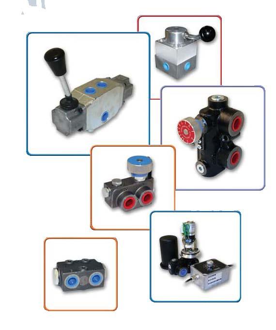
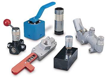
5 Quality Hydraulic Components from the Webtec Range Hydraulic Components Our range of hydraulic control valves are used on a large variety of mobile machinery. The range has evolved from traditional well-tested designs to include many custom features and specially designed flow, pressure and directional control valves. Hydraulic Test Equipment Our range includes over 350 different portable hydraulic testers, flowmeters, pressure transducers, temperature sensors, speed sensors, hydraulic data acquisition and digital display systems. 1.2
6 1.3 How to Order
7 Quality Hydraulic Components from the Webtec Range Section 2 Hydraulic Flow Control Valves Description Page ILFC Series Fixed Flow Pressure Compensated Control Valve 2.1 VFC Series Variable Flow Pressure Compensated Control Valve 2.3 FV 120 Series Fixed Priority Flow Dividers 2.5 FV 200 Series Proportional Flow Dividers 2.7 VFD 50 Series Variable Priority Flow Dividers 2.9 2FV2V Series Variable Priority Flow Dividers FV2V Series Variable Priority Flow Divider with Electric Motor Drive 2.17 FDM Series Variable Priority Flow Divider with Remote Proportional Control FV2V Series Manifold Mounted Variable Priority Flow Divider 2.21 FDC 60 Series Flow Divider Combiner 2.23
8 Hydraulic Flow Control Valves ILFC Series Fixed Flow Pressure Compensated Control Valve Flow Control Valves maintain the flow rate of hydraulic fluid to a specified value. Applications include hydraulic cylinders required to extend or retract at constant speeds and hydraulic motors required to rotate at constant speeds. When used with a fixed delivery pump the excess flow is By- Passed across a relief valve. Specifications Maximum Pressure: 210 bar (working) Features Pressure compensated to ensure a constant flow rate under varying pressures. Pre-set in factory to customer requirements at any flow rate between 1.5 lpm - 16 lpm. Uncontrolled flow is permitted in reverse direction. Zinc plated clear passivate. Cartridge version available, without steel body. Maximum Flow: 16 lpm Porting: BSPP & NPTF - see Table 1 Material: Zinc plated clear passivate Weight: See Table 1 Symbol 2.1
9 Quality Hydraulic Components from the Webtec Range Ordering Codes Typical Code ILFC 16 5 J ILFC - In-line (fixed) Flow Control Flow Size (see Table 1) Factory Preset Flow Rating in lpm Port Thread (see Table 2) Table 1: Dimensions Code Flow Range Port Weight A B C A/F Size Thread (kg) lpm 1 / 4 BSPP lpm 1 / 4 NPTF lpm 3 / 8 BSPP lpm 3 / 8 NPTF Table 2: Porting* Code Thread J BSPP A NPTF Installation Details Dimensions in millimetres A C A/F B Uncontrolled Flow Controlled Flow Section View * Other threads available to special order. 2.2
10 Hydraulic Flow Control Valves VFC Series Variable Flow Pressure Compensated Control Valve Variable Flow Control Valves maintain the flow rate of hydraulic fluid to a selected value. Applications include hydraulic cylinders requiring constant extension or retraction speeds and hydraulic motors requiring constant rotational speeds. When used with a fixed delivery pump the excess flow is By- Passed across a relief valve. Specifications Maximum Pressure: 210 bar (working) Maximum Flow: 55 lpm Porting: BSPP & NPTF Features Pressure compensated to ensure a constant flow rate under varying pressures. Knurled knob enables fast, accurate adjustment of flow rate in one direction (under pressure) from 1.5 lpm to 55 lpm. Knurled knob can be locked in position by a grub (set) screw and provides weatherproof sealing to prevent the adjusting screw from corroding or seizing. Free (uncontrolled) flow is permitted in reverse direction. Special, Uni-directional version available on request. Material: Steel components in an aluminium body Weight: See Table 1 Symbol 2.3
11 Quality Hydraulic Components from the Webtec Range Ordering Codes Typical Code VFC 20 K J VFC - Variable Flow Control Flow Size (Table 1) Adjustment Method (knurled knob) Porting (Table 2) Table 1: Dimensions Code Flow Range Port Size A B C D E F H Weight (kg) lpm 1 / lpm 3 / lpm 1 / Table 2: Porting * Code Thread J BSPP A NPTF Installation Details Dimensions in millimetres B Knurled Knob Adjustment Locking Screw E A H D C Controlled Flow Free Flow F * Other threads available to special order. 2.4
12 FV 120 Series Fixed Priority Flow Dividers Hydraulic Flow Control Valves Priority Type Flow Dividers split a single input flow into a Priority (regulated) flow and a By-Pass (excess) flow which can be returned directly to the oil reservoir or used to power a second system. This often dispenses with the need for another pump to operate a second system. A common application on mobile machinery is to use the Priority (regulated) flow for power steering and the By-Pass (excess) flow for an implement or lift circuit. This ensures the power steering is satisfied first to keep the steering speed constant. Specifications Maximum Pressure: 210 bar (working) Total Flow Capacity: 76 lpm Regulated Flow Capacity: See Table 1, ordering codes Porting: See Table 3, ordering codes Material: Steel components in cast iron body Weight: 1.50 kg Mounting: Two bolt Relief Valve: See Table 2, ordering code Features Priority flow rate is pre-set in factory to customer specifications at any value between 3.78 lpm and 34.1 lpm in increments of 3.78 lpm. Flow through the Priority port will remain constant at the pre-set value as long as input flow equals or exceeds the Priority flow value. Pressure compensated permitting both Priority and By-Pass flows to be used simultaneously at varying pressures without effecting the Priority flow rate. Built-in pressure relief valve protects the Priority circuit from excess pressure and is adjustable from 34.5 bar to 210 bar (Factory set 82.7 bar unless otherwise specified). Symbol P T BP REG 2.5
13 Quality Hydraulic Components from the Webtec Range Ordering Codes Typical Code FV J FV - Valve Type Priority Flow Setting (Table 1) Relief Valve (Table 2) 20 - Basic Type Porting (Table 3) Table 1: Priority Flow Code Flow at Priority Port lpm lpm lpm lpm lpm lpm lpm lpm lpm Table 2: Relief Valve Code Description 0 Without Relief Valve 1 With Relief Valve Table 3: Porting Code Inlet and By-Pass Port Priority and Relief Port A 1 / 2 NPTF 3 / 8 NPTF J 1 / 2 BSPP 3 / 8 BSPP G 7 / 16-20UN #4 SAE ORB 9 / 16-18UN #6 SAE ORB Note: Relief Valve can be adjusted between 34.5 bar and 210 bar. Please specify required setting when ordering otherwise setting will be 82.7 bar. Installation Details Dimensions in millimetres Mtg Holes Ø7.1 Thru By-Pass Port Inlet Port 62.7 P R BP ,5 Priority Port * Other threads available to special order Relief Valve Drain Port 2.6
14 FV 200 Series Proportional Flow Dividers Hydraulic Flow Control Valves Proportional Flow Dividers split a single input flow into two output flows, each output being a fixed proportion of the input. For example, a 50/50 flow divider will always split a single input flow into two equal output flows which could be used to operate two motors at equal speeds. The actual rate of flow from each output is not fixed but will vary as the input flow rate varies. Specifications Maximum Pressure: 207 bar (workings) Features Pressure compensated to keep each output flow at a fixed percentage of the input flow, regardless of pressure variations between the output ports. Three standard models are available giving proportional splits of 25 / 75%, 50% / 50% and 40% / 60%. Other proportional splits are available up to 10%/90% (see ordering codes). Three flow ranges are available; lpm, lpm, lpm (see ordering codes). Total Flow Capacity: 76 lpm Porting: See Table 3, ordering codes Materials: Steel components in cast iron body Weight: 1.47 kg Mounting: Two bolt Symbol 2.7
15 Quality Hydraulic Components from the Webtec Range Ordering Codes Typical Code FV J FV Valve Type Flow Range (Table 1) Output Flow Proportions (Table 2) Porting (Table 3) Table 1: Flow Range Code Recommended Flow Range lpm lpm lpm Table 2: Flow Rates Code A/B Ratio % 1 25/ / / 60 other ratios available up to 10 / 90 Table 3: Porting Code Inlet Port Outlet Ports J 1/ 2 BSPP 3/ 8 BSPP S 3/ 4 BSPP 3/ 4 BSPP Note: S Ported Valve Installation Details 2 Mtg Holes Ø 8.5 Thru (.34 dia) Outlet Port Inlet Port Outlet Port * Other threads available to special order. 2.8
16 VFD 50 Series Variable Priority Flow Dividers Hydraulic Flow Control Valves Priority Type Flow Dividers split a single input flow into a Priority (regulated) flow and a By-Pass (excess) flow which can be returned directly to the oil reservoir or used to power a second system. In many instances this dispenses with the need for another pump to operate a second system. Specifications Maximum Pressure: 250 bar (working) Features Clearly marked hand-dial permits fast visual adjustments to pre-determined Priority flow and fast easy adjustment of Priority circuit to meet varying requirements. Pressure compensated permitting both Priority and By-Pass flows to be used simultaneously at varying pressures without effecting the Priority flow rate. Total Flow Capacity: 50 lpm Regulated Flow Capacity: See Table 1, ordering codes Porting: See Table 2, ordering codes Material: Steel components in cast iron body: aluminium knob. Weight: 0.75 kg Mounting: 2 Bolt - BSPP or NPTF Ported 3 Bolt - Manifold Symbol P BP REG 2.9
17 Quality Hydraulic Components from the Webtec Range Ordering Codes Typical Code VFD50 30 T Valve Type Regulated Flow Capacity (Table 1) Porting (Table 2) Table 1: Regulated Flow Code Regulated Flow lpm lpm Table 2: Porting* Code Port Type T 3/ 8 BSPP x 3 Ports M Manifold Mounted A 3/ 8 NPTF x 3 Ports Typical Pressure Drop VFD 50 Series Curve established using hydraulic mineral oil ISO 32 with viscosity of 21 centistokes at 50 C 30 Pressure Drop (bar) Input Flow (lpm) Installation details Dimensions in millimetres By-Pass Port 50.0 Inlet Mtg Holes Ø 5.56/5.57 thru Ø 9.5 mm S/Face Priority Port * Other threads available to special order. 2.10
18 2FV2V Series Variable Priority Flow Dividers Hydraulic Flow Control Valves Priority Type Flow Dividers split a single input flow into a Priority (regulated) flow and a By-Pass (excess) flow which can be returned directly to the oil reservoir or used to power a second system. In many instances this dispenses with the need for another pump to operate a second system. Specifications Maximum Pressure: 250 bar (working) Total flow capacity: 114 lpm Regulated flow capacity: See Table 2, ordering codes Porting: See Table 3, ordering codes Material: Steel components in cast iron body painted black; aluminium knob (steel knob optional) Weight: 2.10 to 3.50 Kg Mounting: Two bolt - M8 or 5/16 (Except manifold version which uses 4 bolts) Relief valve (optional): Adjustable between bar Max. Priority flow - 50 lpm Check valve (optional): 250 bar working pressure (Anti-cavitation check valve available) Symbol Features Clearly marked single-turn hand dial permits fast visual adjustments to pre-determined Priority flow and fast easy adjustments of Priority circuit to meet varying requirements. Pressure compensated permitting both Priority and By-Pass to be used simultaneously at varying pressures without affecting the Priority flow rate. All models (except manifold mount) can be supplied with an adjustable pressure relief valve or check valve on Priority flow. Anti-cavitation check valve can be routed between the By-Pass and Priority flows. Anti-tamper locknut option available for all models, Contact Sales Office for more information. For intermittent reverse flow, needle valve pull back facility available on request. Remote control versions available see 2.17 & 2.19 IN BP REG 2.11
19 Quality Hydraulic Components from the Webtec Range Ordering Codes Typical Code M 2FV2V 125 J ( ) Manifold mounting available on 2FV2V model only Valve Type (Table 1) Regulated Flow Capacity (Table 2) Porting (Table 3) Pressure Setting (bar, if Relief Valve required) Table 1: Valve Type Code 2FV2V RV2FV2V RVXD2FV2V CK2FV2V AC2FV2V M2FV2V PB2FV2V Description No Relief Valve Relief Valve between Priority and By Pass Flow Port Externally Drained Relief Valve Check Valve between Priority and Inlet Flow Port Anti-cavitation Check Valve between By-Pass and Priority Flow Port Manifold Mounted Pull Back Poppet Table 2: Regulated Flow Code Regulated Flow lpm lpm lpm lpm lpm lpm lpm Table 3: Porting* Code Port Threads Inlet Regulated Relief Valve External Drain Flow and Excess Flow where fitted J 3 / 4 BSPP 1 / 4 BSPP A 3 / 4 NPTF 1 / 4 NPTF M M22 x 1.5, M27 x 2 M14 x 1.5 G 1-1 / 16-12UN #12 SAE ORB 9 / 16-18UN #6 SAE ORB H 1 / 2 BSPP 1 / 4 BSPP K Manifold mounted (custom hole pattern) N/A * Other threads available to special order. Note: M22 only available in flow code 030 to 125 M27 only available in flow code 200 to / 2 BSPP only available in flow code 030 to
20 Hydraulic Flow Control Valves 12 Typical Pressure Drop 2FV2V Series (in forward direction) Pressure Drop (bar) Input Flow (lpm) 50 Typical Pressure Drop CK2FV2V Series (in reverse direction) Pressure Drop (bar) Needle valve closed Needle valve open Reverse Flow (lpm) Curve established using hydraulic mineral oil ISO 32 with viscosity of 21 centistokes at 50 C Flow (lpm) Typical flow control performance - varying input conditions Pressure (psi) Time (seconds) Priority flow Input flow Priority pressure 2.13
21 Quality Hydraulic Components from the Webtec Range Installation Details Dimensions in millimetres (PB) 2FV2V (No Relief Valve) By-Pass Flow Port 78 Inlet Symbol 136 BP 46 REG IN 62.7 Priority IN BP REG Mtg Holes Ø8.5 Thru RV2FV2V (Internal Relief Valve between Priority and By-Pass Flow Ports) Inlet 78 Symbol REG PR Priority Port Mtg Holes Ø8.5 Thru BP By-Pass Flow Port PR BP REG RV2FV2V with REG RELIEF to BP RVXD2FV2V (Externally drained Relief Valve) Inlet 78 Symbol REG PR Priority Port Mtg Holes Ø8.5 Thru BP By-Pass Flow Port PR BP REG RVXD2FV2V with REG RELIEF to TANK 2.14
22 Hydraulic Flow Control Valves CK2FV2V (Internal Check Valve between the Priority and Inlet Flow Ports) Inlet 78 Symbol REG PR BP PR BP REG T Priority Port Mtg Holes Ø8.5 Thru 49.5 By-Pass Flow Port AC2FV2V (Internal Anti-cavitation Check Valve between the By-Pass and Priority Flow Ports) Inlet 78 Symbol REG PR BP PR BP REG T Priority Port Mtg Holes Ø8.5 Thru By-Pass Flow Port 2.15
23 Quality Hydraulic Components from the Webtec Range Sectioned View Circuit 1 Circuit 2 Circuit Suggestions 1 Variable Speed of Hydraulic Motor Drive on Agricultural Tractor This circuit gives the capability to vary the speed of a hydraulic motor as required. Also, for a given control knob setting, the hydraulic motor speed stays constant regardless of the tractor speed. 2 Two Circuits From a Single Pump Using only one pump, this circuit gives speed control of the hydraulic motor and powers a hydraulic cylinder. Each function can be used either simultaneously or independently because pressure variations between regulated and By-Pass flows do not effect the flow on the regulated circuit. Circuit 3 3 Multiple Circuits From a Single Pump Using one pump, this circuit gives independently variable speed drive from three hydraulic motors. Motors can be used simultaneously or independently. 2.16
24 2FV2V Series Variable Priority Flow Divider with Electric Motor Drive Hydraulic Flow Control Valves Priority Type Flow Dividers split a single input flow into a Priority (regulated) flow and a By-Pass (excess) flow which can be returned directly to the oil reservoir or used to power a second system. In many instances this dispenses with the need for another pump to operate a second system. Specifications Maximum Pressure: 250 bar Total Flow Capacity: 114 lpm Regulated Flow Capacity: See Table 2, ordering codes Porting: See Table 1 Material: Steel components in cast iron body painted black Features Minimum to full Priority flow in 15 seconds. Powered from Nom. 12 VDC (12-16 VDC). Electric motor drive permits adjustment from a position away from the valve such as a cab or a control panel. Pressure compensated permitting both Priority and By-Pass flows to be used simultaneously at varying pressures without effecting the Priority flow rate. Can be used as unidirectional two port in line flow control by plugging the By-Pass flow port. (Note: in this configuration a relief valve must be used on the inlet line). 24 volt versions available on request Weight: 2.75 kg Power Supply: 12V (24V at special request) Peak Current: 1.0 Amp Symbol M P BP REG 2.17
25 Quality Hydraulic Components from the Webtec Range Ordering Codes Typical Code 2FV2V 125 J E Valve Type Regulated Flow Capacity (Table 2) Porting (Table 1) Motor Drive Table 3: Porting* Code Port Threads Inlet Regulated Relief Valve External Drain Flow and Excess Flow where fitted J 3 / 4 BSPP 1 / 4 BSPP A 3 / 4 NPTF 1 / 4 NPTF M M22 x 1.5, M27 x 2 M14 x 1.5 G 1-1 / 16-12UN #12 SAE ORB 9 / 16-18UN #6 SAE ORB H 1 / 2 BSPP 1 / 4 BSPP * Other threads available to special order. Note: M22 only available in flow code 030 to 125 M27 only available in flow code 200 to / 2 " BSPP only available in flow code 030 to 125 Table 2: Regulated Flow Code Regulated Flow lpm lpm lpm lpm lpm lpm lpm Installation Details Dimensions in millimetres Ø Ø REG. IN. 2 Core PVC Insulated Cable. Power supply to Blue Brown Cable Cable Function -ve +ve Valve opens +ve -ve Valve closes 2.18

26 Hydraulic Flow Control Valves FDM Series Variable Priority Flow Divider with Remote Proportional Control The FDM remote control flow divider is ideally suited for the agricultural and industrial user seeking a cost-effective method of controlling hydraulic motor speed. The priority flow port gives an output independent of load pressure while the By-Pass port can be used to power a secondary circuit. Specifications Maximum pressure: 250 bar Total flow capacity: 114 lpm Regulated flow capacity: See Table 2 Porting: See Table 1 Material: Steel components in a cast iron body. Drive mechanism mounted on aluminium supports Weight: 2.75 kg Power supply: 9-28 V Peak current: 2.5 A Average current: < 100 ma Symbol Features Minimum to maximum priority flow in less than 3 seconds (at full pressure) 9-28 V D.C. supply enables unit to be powered from a vehicle supply Remote control using: Potentiometer (shown above) 0-5 VDC 4-20 ma loop Remote operating distance: up to 40 m Pressure compensated permitting both priority and By-Pass flow to be used simultaneously at varying pressures without affecting the priority flow rate Automatic current limiting to prevent overheating and motor overload Valve settings immune to power failure Tolerant to vibration and oil contamination Valve cover zinc plated and Teflon coated for corrosion resistance Teflon is a Registered Trademark of DuPont Designed to meet IP67 Range of cables available please contact sales office M IN BP REG 2.19
27 Quality Hydraulic Components from the Webtec Range Ordering Codes Typical Code FDM 125 J P Valve Type Regulated Flow Capacity (Table 2) Porting (Table 1) Control (Table 3) Table 1: Porting* Code Port Threads Inlet Regulated Relief Valve External Drain Flow and Excess Flow where fitted J 3 / 4 BSPP 1 / 4 BSPP A 3 / 4 NPTF 1 / 4 NPTF M M22 x 1.5, M27 x 2 M14 x 1.5 G 1-1 / 16-12UN #12 SAE ORB 9 / 16-18UN #6 SAE ORB H 1 / 2 BSPP 1 / 4 BSPP * Other threads available to special order. Note: M22 only available in flow code 030 to 125 M27 only available in flow code 200 to / 2 BSPP only available in flow code 030 to 125 Installation Details - Value Dimensions in millimetres Table 2: Regulated Flow Code Regulated Flow lpm lpm lpm lpm lpm lpm lpm Table 3: Control Code Control P Potentiometer 5 V 0-5 VDC ma 4-20 ma Ø76 REG IN Cable entry at base Ø85 60 Mounting holes Ø Webtec Products Limited *Other threads available to special order. 2.20
28 M2FV2V Series Manifold Mounted Variable Priority Flow Divider Hydraulic Flow Control Valves Priority Type Flow Dividers split a single input flow into a Priority (regulated) flow and a By-Pass (excess) flow which can be returned directly to the oil reservoir or used to power a second system. In many instances this dispenses with the need for another pump to operate a second system. Specifications Maximum Pressure: 250 bar (working) Total Flow Capacity: 114 lpm Regulated Flow Capacity: See Table 1, ordering codes Material: Steel components in cast iron body Features Pressure compensated permitting both Priority and By-Pass flows to be used simultaneously at varying pressures without affecting the Priority flow rate. Can be used as uni-directional two port in line flow control by plugging the By-Pass flow port. (Note: in this configuration a relief valve must be used on the inlet line). Manifold Mounted. Anti-tamper locknut option available for all models, Contact Sales Office for more information. For intermittent reverse flow, needle valve pull back facility available on request. Weight: 2.75 kg Mounting: 4 Bolt Manifold Symbol IN BP REG 2.21
29 Quality Hydraulic Components from the Webtec Range Ordering Codes Typical Code M 2FV2V 125 K Manifold Mounted Valve Type Regulated Flow Capacity (Table 1) Control Type (Table 2) Table 1: Regulated Flow Code Control Type K lpm lpm lpm lpm Table 2: Porting Code Description K Manifold Mounted Installation Details ( K Type) Dimensions in millimetres 78 Inlet Port By-Pass Flow Port 23.9 IN REG IN BP PRI BP Mtg. holes dia. 8.5 thro Other 3 Mtg. Holes dia Priority Port 2.22
30 FDC 60 Series Flow Divider Combiner Hydraulic Flow Control Valves A Flow Divider-Combiner will divide a single flow into two separate flows which will always be in the same ratio to each other regardless of any pressure differential between the two lines. If the flow is reversed (e.g. return stroke of two cylinders) the return flows are held in the same ratio to each other and combined into a single flow, regardless of individual loads on the cylinders A common application is to keep two cylinders (or motors) in close unison when loads on them are unequal. The valves may also be used in series to operate more than two circuits. Features Pressure compensated to keep the two divided flow rates at the same ratio regardless of pressure variations between them. Flow ratios are pre-set at factory from 50% - 50% up to 10% - 90%. Flow ranges are available from 5 lpm to 70 lpm. Cast iron/hardened steel construction (no aluminium) makes it suitable for mining applications. Specifications Maximum Pressure: 310 bar (working) Total Flow Capacity: 70 lpm Porting: See Table 2, ordering codes Materials: Steel components in cast iron body Weight: 2.05 kg Mounting: Three bolt Symbol Port P Port A Port B 2.23
31 Quality Hydraulic Components from the Webtec Range Ordering Codes Typical Code FDC A40% B60% FDC 60 - Valve Type Recommended Flow Range (Table 1) Porting (Table 2) Divider Ratio (Table 3) Table 1: Recommended Flow Range Code Flow Range lpm lpm lpm lpm lpm lpm lpm lpm Table 3: Divider Ratio A B 50% 50% thru' 10% 90% Note: Either outlet port (A or B) may be designated to take either leg of the ratios. The example shown designates 40% at A and 60% at B. Any ratio from 50% - 50% to 90% - 10% may be specified. Table 2: Porting (choose from following codes) Code Port P Port A Port B 1 M18 x 1.5 M18 x 1.5 M18 x M22 x 1.5 M18 x 1.5 M18 x / 8 BSPP 3 / 8 BSPP 3 / 8 BSPP 4 1 / 2 BSPP 3 / 8 BSPP 3 / 8 BSPP 5 1 / 2 BSPP 1 / 2 BSPP 1 / 2 BSPP 6 7 / 8-14UN #10 SAE ORB 3 / 4-16UN #8 SAE ORB 3 / 4-16UN #8 SAE ORB 7 M27 x 2 M22 x 1.5 M22 x / 2 NPTF 1 / 2 NPTF 1 / 2 NPTF Installation Details Dimensions in millimetres Mtg Holes 6.75 dia B P 40 A 45 * Other threads available to special order. 2.24
32 Hydraulic Flow Control Valves Intentionally left blank 2.25
33 Quality Hydraulic Components from the Webtec Range Section 3 Hydraulic Directional Control Valves and Check Valves Description Page SV80 Series Diverter Valve 3.1 DV80 Series Diverter Valve Series Rotary Shear Valve 3.5 NR Series Non-Return Valve 3.9 SHV Shuttle Valve 3.11 BG4D 1/2 BSPP Lever Operated Valves 3.13 BG4D 1/2 BSPP Cam Operated Valves 3.15 BG4D 1/2 BSPP Air Pilot Operated Valves 3.17 BG4D 1/2 BSPP Oil Pilot Operated Valves 3.19
34 Hydraulic Directional Control Valves and Check Valves SV80 Series Diverter Valve A Diverter Valve provides an alternative to the standard directional control valve when a neutral (centre) position is not required. It allows flow to be directed into either of two lines which enables fast changing from one system to another, or from one system to tank thus providing an idling circuit. Other applications may be as a safety lock preventing accidental operation of separate functions which should not operate together and the selection of attachments as on a farm tractor. Specifications Maximum Working Pressure: 210 bar Features Flow may be directed by mechanically pushing the spool with spring offset or by a mechanical push pull operation in which case the valve stem is threaded or fitted with a moulded knob. Customer can select from one of two spool types allowing flow to be diverted from one line to another or from system to tank. A choice of port threads are available. Special versions also available. Maximum Flow: 80 lpm Porting: See Table 2, ordering codes Material: Stainless steel spool in cast iron body Weight: 2 kg (approx.) Mounting: Two bolt Symbol For valve model number SV80-A-J-S (see ordering codes) A B P 3.1
35 Quality Hydraulic Components from the Webtec Range Ordering Codes Typical Code SV80 A J S Basic Valve Spool Type (Table 1) Porting (Table 2) Operation (Table 3) Table 1: Spool Type Code Spool Type A B Table 2: Porting Code Porting J 1 / 2 BSPP G 7 / 8-14UN #10 SAE ORB M M22 x 1.5 A 1 / 2 NPTF Table 3: Operation Code Operation S Spring Offset, Mechanical Push M Manual, Push - Pull T Threaded, Push - Pull Installation Details Dimensions in millimetres A Spool - Inlet to Port A in position shown below B Spool - All Ports closed in position shown below Threaded Push, Pull Type Manual Push, Pull Type 3 / 8 UNC Thread A A IN 57 IN B B 41 2 Mtg. holes Ø8.7mm Thru A Spool Movement 11 mm IN Spring Offset Type B 3.2
36 Hydraulic Directional Control Valves and Check Valves DV80 Series Diverter Valve A Diverter Valve provides an alternative to the standard directional control valve when a neutral (centre) position is not required. It allows flow to be directed into either of two lines which enables fast changing from one system to another, or from one system to tank thus providing an idling circuit. Other applications may be as a safety lock preventing accidental operation of separate functions which should not operate together and the selection of attachments as on a farm tractor. Specifications Maximum Working Pressure: 210 bar Features Flow may be directed by mechanically pushing the spool with spring offset. Customer can select from one of two spool types allowing flow to be diverted from one line to another or from system to tank. A choice of port threads and spool end types are available. Spring and spool end protected from environment in sealed housing. Special versions also available Maximum Flow: 80 lpm Porting: See Table 2, ordering codes Material: Stainless steel spool in cast iron body Weight: 2 kg (approx.) Mounting: Two bolt Symbol For valve model DV80-A-J-B (see ordering codes) A B P 3.3
37 Quality Hydraulic Components from the Webtec Range Ordering Codes Typical Code DV80 A J R Basic Valve Spool Type (Table 1) Porting (Table 2) Spool End Type (Table 3) Table 1: Spool Type Table 2: Porting Table 3: Spool End Type Code Spool Type Code Porting Code Spool end type A J 1/ 2 BSPP R Roller B G 7/ 8-14UN #10 SAE ORB B Ball Installation Details Dimensions in millimetres A Spool - Inlet to Port A in position shown below B Spool - All Ports closed in position shown below M Manual A B IN Displacement 10.9 A B 60.9 IN Mount Holes Ø Mount Holes Ø Manual Push, Pull Type Roller Spring Offset Displacement 10.9 A B IN Mount Holes Ø 8.7 Ball Spring Offset
38 Hydraulic Directional Control Valves and Check Valves 180 Series Manual Directional Control Valve The Directional Control Valve of the rotary spool type consists of a rotor which is rotated with respect to the valve body. When the rotor is placed in selected positions inlet and outlet ports are connected in various combinations permitting the start, stop or directional change of fluid under pressure. The functions specific to a valve depends primarily on rotor type selected. Specifications Maximum Working Pressure: 700 bar Spring centred models will not spring return to centre when operated over 207 bar. Maximum Flow: 38 lpm See table 3, ordering codes for available flow sizes. Features Pressure loaded seats working against optically flat rotors automatically compensated for valve wear to assure near zero leakage even after more than 500,000 cycles. Customer can select from numerous variations including 7 flow patterns, 3 flow ratings, many porting configurations, ball or offset ball operating handles, spring centring and detents. Valves may be in-line, panel or manifold mounted. Valve can be used in series without drain up to a max working pressure of 250 bar. Porting: See Table 2, ordering codes Material: Steel components in aluminium body Weight: 1.13 kg Mounting: Pipe or manifold in any position Symbol A B P T 3.5
39 Quality Hydraulic Components from the Webtec Range Ordering Codes Typical Code 180 E I F Valve Model (Table 1) Port Size and Location (Table 2) Flow Size (Table 3) Handle Type and Rotor Action (Table 4) Note: Models 185 and 187 available in 1 and 2 flow sizes only Table 1: Valve Model Code Symbol Table 2: Port Size and Location Code C1 C2 C3 C4 P1 P2 T1 T2 Thread type A 3 / 8 / 8 / 8 / 8 / 4 1 / 4 / 4 1 / 4 C * 3 / / 8 / 8 0 / / 8 = 3 / 8 BSPP / 4 = 1 / 4 NPTF E 3 1 / 1 4 / 4 / 4 / 4 / 8 / 8 3 / 8 / 8 F 3 / 8 / 8 / 8 / 8 / 4 1 / 4 / 4 1 / 4 K * 3 / / 8 / 8 0 / / 8 = 3 / 8 NPTF / 4 = 1 / 4 NPTF L 3 1 / 4 / 4 / 4 1 / 4 / 8 / 8 3 / 8 / P 1 P 1 P 2 Note: 0 = C Bore for 014 O Ring (4 O Rings included) = Ports shipped plugged * Manifold mounted models utilise 5/16-18 UNC through bolts provided for mounting to manifold ( C porting only) C 1 C 2 C 4 T 2 Table 3: Flow Size C 3 T 1 T 1 Code Description Curve MAX Pressure 0 15 lpm A Non - interflow* 10,000 psi lpm B Low Interflow* 5,000psi 2 38 lpm C Medium Interflow* 3,000psi *Interflow = flow through valve in intermediate position Pressure Drop (bar) Typical Performance Drop Curve Established using Hydraulic oil with viscosity of 27.4 centisokes at 49 C Flow (lpm) A B C Table 4: Handle Type & Rotor Action Code Type Action D Ball Detented Action E Ball Spring Centred Action F Offset Ball Detented Action + Panel Mount G Offset Ball Spring Centred Action + Panel Mount 3.6
40 Hydraulic Directional Control Valves and Check Valves Sectional View Panel mount hole dia. 17.5mm Clearance max panel thickness 5mm Position Neutral Ø /16-18 UNC Thru. Bolts for C Porting /16-18 UNC - 2B x Deep 4 Holes (All Valves except C Porting) 3.7
41 Quality Hydraulic Components from the Webtec Range Installation Details Panel Mounted Dimensions in millimetres /16-18 UNC - 2B x 7.9 mm Deep 4 Mounting Holes * (For Panel Mounted Valves only) Not used with C Porting 23.9 Tank Port 47.6 Neutral Position /16-18 UNC - 2B x 15.7 mm 2 Mounting Holes Cylinder Port Cylinder Port
42 Hydraulic Directional Control Valves and Check Valves NR Series Non-Return Valve Check (Non-Return) Valves stop fluid flow in one direction while permitting free flow in the opposite direction. The force exerted by fluid entering the valve in the free flow direction unseats a spring loaded poppet permitting fluid to pass. The fluid pressure required to unseat the poppet is known as the cracking pressure. Both the spring force and the fluid force in the opposite direction push the poppet against the seat thus preventing fluid passage. Features Straight through porting allows the valve to be connected directly in-line thus making the best use of restricted space. Customer can select from 7 valve sizes offering a range of flow ratings from lpm and 4 cracking pressure settings ranging from 0.35 to 4.5 bar. Specifications Maximum Working Pressure: 210 bar Cracking Pressure: See Table 2, ordering codes Rated Flow: See Table 1, ordering codes Porting: See Table 1, ordering codes Material: Steel body Weight: See Table 1, ordering codes Symbol 3.9
43 Quality Hydraulic Components from the Webtec Range Ordering Codes Typical Code NR 25 5 NR - Non-Return Valve Valve Size (Table 1) Cracking Pressure (Table 2) Table 1: Valve Size Code Port Size Weight Rated Flow Dim A Dim B 25 1/ 4 BSPP 0.14 kg 15 lpm / 8 BSPP 0.18 kg 27 lpm / 2 BSPP 0.33 kg 52 lpm / 4 BSPP 0.71 kg 85 lpm BSPP 0.9 kg 105 lpm / 4 BSPP 2.3 kg 175 lpm / 2 BSPP 2.3 kg 260 lpm Table 2: Cracking Pressure Code Pressure bar bar bar bar Installation Details Dimensions in millimetres (see table 1 above) Dim B (Across Flats) Dim A BSPP Ports Both Ends Arrow indicates direction of flow 3.10
44 SHV Hydraulic Directional Control Valves and Check Valves Shuttle Valve The Shuttle Valve permits either of two input flows to be directed to a common outlet port. Flow entering one of the inlets causes a steel ball to travel along a centre bore to seal off the alternative inlet whilst leaving the outlet port free and allowing unimpeded oil flow through the valve. Specifications Maximum Working Pressure: 250 bar Features Fast switching between 2 inlet flows. Free flow between inlet and outlet ports. 2 bolt mounting. Chemically blacked finish. Maximum Flow: 20 lpm Porting: 1/4 BSPP Material: Body and adaptor chemically blacked steel. Steel ball. Symbol 3.11
45 Quality Hydraulic Components from the Webtec Range Ordering Codes Typical Code SHV 20 J SHV - Shuttle Valve 20 - Flow Rating J - 1 / 4 BSPP Porting 5 Typical Performance 4 Pressure (bar) Flow (lpm) Installation Details Dimensions in millimetres Mounting Holes 6.5 dia

46 Hydraulic Directional Control Valves and Check Valves BG4D 1/2 BSPP Lever Operated Directional Control Valve Description Nominal flow rate - 55 lpm (see graph for further details) Max. operating pressure bar Max. pressure on T port bar Recommended operating viscosity range - min. 13 c/st - max 800 c/st Recommended operating temperature range - min C - max 80 C Recommended filtration - 25 microns or better Seals medium nitrile (consult Technical Sales for alternatives) Leakage - typical max. allowable on works test 15cc at 135 bar, oil 35 c/st at 40 C Mounting unrestricted General Arrangement Directional functions N.B. Lever fitted on A Port end Lever pulled away from valve P to A Lever pushed towards valve P to B Force required to move lever at standard knob centre - 4.5kg Weight: 4.5 kg approx B A A & B Ports tapped 1/2 BSPP 22 1/ T approx off fixing holes M Deep P & T Ports tapped 1/2 BSPP Typ both sides 9.5 = =
47 Quality Hydraulic Components from the Webtec Range Pressure Drop Curve Pressure bar psi Spool type A C Flow selected B-T P-B P-T P-A A-T B-T P-A A-T P-B Curve number Spool type G H Flow selected B-T P-B P-T P-A A-T B-T P-A A-T P-B Curve number Pressure drop gpm lpm Flow Ordering Code Special Preferred standard Others to order Spool Type A C G H I J Spring centred. 3 position Spring centred. 2 position. Stop in lever cap Spring centred. 2 position. Stop in end cap Detent. 3 position Detent. 2 position. Stop in lever cap Detent. 2 position. Stop in end cap Spring offset. P to B 2 position. Stop in end cap. Microswitch fitted ACGH spools spring centred only 4 B C 3 E F H Lever type Standard 22 1/2 Lever. Facing up-direction of ports. 90 Lever. Facing up-direction of ports. Eye-end Lever. Facing up-direction of ports. Straight Lever. Facing up-direction of ports. As E but facing down. Opposite ports. As H but facing down. Opposite ports. As J but facing down. Opposite ports. As A but facing down. Opposite ports. E H J A B G F K Pilot operated Service Port Lock Addition. A or H Spools only Lock on Port A. Lock on Port b. Lock on both ports. A B C Special A B P T M O O Special Spring centred from P to A. Opposite end detented. 2 Detent Stop in end lever cap Sprung P to B. Stop in end lever cap. J E B Hose rewind valve Example BG4D 081 C E A C
48 Hydraulic Directional Control Valves and Check Valves BG4D 1/2 BSPP Cam Operated Directional Control Valve Description Nominal flow rate - 55 lpm (see graph for further details) Max. operating pressure bar Max. pressure on T port bar Recommended operating viscosity range - min. 13 c/st - max 800 c/st Recommended operating Temp. min. -30 C - max 80 C Recommended filtration - 25 microns or better Seals medium nitrile (consult Technical Sales for alternatives) Leakage - typical max. allowable on works test 15cc at 135 bar, oil 35 c/st at 40 C Mounting unrestricted Directional functions N.B. Cam actuator fitted on A port end Cam spring offset P to B Cam depressed P to A Force required to depress Cam start kg, Full - 36 kg General Arrangement Weight 4.7kg Travel B A 2 Position Valve A & B Ports Tapped 1/2 BSPP Travel Position Valve 4 Off Fixing Holes M8 x 12.7 Deep T P & T Ports Tapped 1/2 BSPP Typ. Both Sides
49 Quality Hydraulic Components from the Webtec Range Pressure Drop Curve Pressure bar psi 220 Spool type A C Flow selected B-T P-B P-T P-A A-T B-T P-A A-T P-B Curve number Spool type G H Flow selected B-T P-B P-T P-A A-T B-T P-A A-T P-B Curve number Pressure Drop gpm Flow lpm Ordering Code Spool Type Spool Control Operation A B P T A Spring P to B Allows full spool travel 8 Cam Operated C C Spring to centre condition. Allowing 9 half spool travel Example BG4D 081 A 9 C 3.16
50 Hydraulic Directional Control Valves and Check Valves BG4D 1/2 BSPP Air Pilot Operated Directional Control Valve Description Nominal flow rate - 55 lpm (see graph for further details) Max. operating pressure bar Max. pressure on T port bar Recommended operating viscosity range - min. 13 c/st - max. 800 c/st Recommended operating temperatures - min. -30 C - max. 80 C Recommended filtration - 25 microns or better Seals medium nitrile (consult Technical Sales for alternatives) Leakage - typical max. allowable on works test 15cc at 135 bar, oil 35 c/st at 40 C Directional functions Air signal applied to port A end - P to A Air signal applied to port B end - P to B Air pilot operating pressure - min. 5 bar, max. 10 bar Air actuator volume 15 cc General Arrangement Weight 4.1 kg A & B Ports Tapped 1/2 BSPP 2 Ports Tapped 1/8 BSPP A B Double Pilot Operated P P & T Ports Tapped 1/2 BSPP Typ Both Sides 4 Off Fixing Holes M8 x 12.7 Deep 38.1 Single Pilot Operated
51 Quality Hydraulic Components from the Webtec Range Spool type A C Flow selected B-T P-B P-T P-A A-T B-T P-A A-T P-B Curve number Spool type G H Flow selected B-T P-B P-T P-A A-T B-T P-A A-T P-B Curve number Spool Type Spool Control Operation A B P T A C P P P Spring Centred Spring Offset P to B 4 6 Double Air Pilot Spool control 4 only Single Air Pilot Spool control 4, 6 P O G P P Springless 7 Springless double Air Pilot Q A B H P T Example BG4D 081 G 7 Q A 3.18

52 Hydraulic Directional Control Valves and Check Valves BG4D 1/2 BSPP Oil Pilot Operated Directional Control Valve Description Nominal flow rate - 55 lpm (see graph for further details) Max. operating pressure bar Max. pressure on T port bar Recommended operating viscosity range - min. 13 c/st - max. 800 c/st Recommended operating temperatures - min. -30 C - max. 80 C Recommended filtration - 25 microns or better Seals medium nitrile (consult Technical Sales for alternatives) Leakage - typical max. allowable on works test 15cc at 135 bar, oil 35 c/st at 40 C Mounting unrestricted Directional functions Air signal applied to port A end - P to A Air signal applied to port B end - P to B Pilot operating pressure - min. 10 bar, max. 135 bar Pilot volume 7.5cc General Arrangement A & B Ports Tapped 1/2 BSPP A B 2 Ports Tapped 1/4 BSPP P Off Fixing Holes M8 x 12.7 Deep P & T Ports tapped 1/2 BSPP Typ Both Sides
53 Quality Hydraulic Components from the Webtec Range Pressure Drop Curve Pressure bar psi Spool type A C Flow selected B-T P-B P-T P-A A-T B-T P-A A-T P-B Curve number Spool type G H Flow selected B-T P-B P-T P-A A-T B-T P-A A-T P-B Curve number Pressure Drop gpm Flow lpm Ordering Code Spool Type Open Centre Closed Centre Tandem Centre Float Centre A C G H Spool Control A B P T A B P T A B P T Operation Double Oil Pilot Spool control 4 only Single Oil Pilot Spool control 4, 6 Springless Double Oil Pilot D N L Pilot Operated Service Port Lock Addition A or H Spools Only Lock on Port A Lock on Port B Lock on Both Ports A B C Example BG4D 081 H 6 L B 3.20
54 Hydraulic Directional Control Valves and Check Valves Intentionally left blank 3.21
55 Quality Hydraulic Components from the Webtec Range Section 4 Hydraulic Relief Valves Description Page RV 020 Direct In-Line Relief Valve 4.1 RV 050 Pressure Relief Valve 4.3 RV 5 Pressure Relief Valve 4.5 RV 125 Pressure Relief Valve 4.7
56 Hydraulic Relief Valves RV 020 Direct In-line Relief Valve Pressure Relief Valves limit the maximum working pressure of a hydraulic system to a pre-determined rating thus providing protection against the overloading of system components. Direct acting relief valves unload flow to tank when system pressure is sufficient to compress a spring which unseats a poppet. They have a high tolerance to contamination and are generally used for low flow rates where precise pressure control is not critical. Specifications Maximum Pressure: 210 bar Maximum Flow: 20 lpm Features Direct acting in-line relief valve giving high tolerance to particle contamination. Quick response provides protection against shock loads. Relief pressure is factory set to customer requirements within a range between bar. Straight through porting allows the valve to be connected directly in-line with a T piece thus making the best use of restricted space. Provides protection against thermal expansion of fluids. Porting: See Table 1, ordering codes Material: Steel components in High Tensile Aluminium body Weight: kg Symbol 4.1
57 Quality Hydraulic Components from the Webtec Range Ordering Codes Typical Code RV J A RV020 - Valve Type Relief Pressure Setting in bar between bar Porting (Table 1) A - Design Standard Table 1: Inlet Porting Code Inlet Port Threads A 3 / 8 NPTF J 3 / 8 BSPP Typical Characteristics (at one pressure setting) Pressure (bar) Flow (lpm) Curve established using hydraulic mineral oil with viscosity of 27.4 centistokes at 49 C Installation Details Dimensions in millimetres Inlet: 3/8 Male (See Table 1) Outlet: 3/8 NPSM* Pressure Inlet Return To Tank * National pipe straight mechanical. 4.2
58 Hydraulic Relief Valves RV 050 Pressure Relief Valve Pressure Relief Valves limit the maximum working pressure of a hydraulic system to a pre-determined rating thus providing protection against the overloading of system components. Direct acting relief valves unload flow to tank when system pressure is sufficient to compress a spring which unseats a poppet. They provide high tolerance to contamination and are generally used for low flow rates where precise pressure control is not critical. Specifications Maximum Pressure: 210 bar Maximum Flow: 50 lpm Porting: See Table 2, ordering codes Material: Steel components in high tensile aluminium body Features Direct acting, in-line relief valve giving high tolerance to contamination. Quick response provides protection against shock loads. Relief pressure is adjustable by means of a screw and locknut. See Table 1, ordering codes for available adjustment ranges. Provides protection against thermal expansion of fluid. Can be used as a remote control for a pilot operated relief valve by substituting for the built in direct acting relief valve of the pilot operated valve. Flow through pressure ports enable the valve to be connected in-line with mounting versatility and convenience. Weight: 0.5 kg Symbol Pressure Pressure Tank 4.3
59 Quality Hydraulic Components from the Webtec Range Ordering Codes Typical Code RV050 1 J S RV050 - Valve Type Adjustment Range (Table 1) Porting (Table 2) Adjustment Method (Table 3) Table 1: Adjustment Range Table 2: Porting Table 3: Adjustment Method Code Port Threads Code Port Thread Code Adjustment bar I 3 / 4-16UN #8 SAE ORB S Screwdriver bar J 1 / 2 BSPP K Knob Typical Characteristics (at one Pressure Setting) 200 Inlet Pressure (bar) Flow (lpm) Curve established using hydraulic mineral oil with viscosity of 27.4 centistokes 49 C Installation Details Dimensions in Millimetres Remove cap for screwdriver adjustment Return Port max Pressure Port Knob Adjustment 4.4
60 Hydraulic Relief Valves RV 5 Pressure Relief Valve Pressure Relief Valves limit the maximum working pressure of a hydraulic system to a pre-determined rating thus providing protection against the overloading of system components. Direct acting relief valves unload flow to tank when system pressure is sufficient to compress a spring which unseats a poppet. They have a high tolerance to contamination and are generally used for low flow rates where precise pressure control is not critical. Specifications Maximum Pressure: 276 bar Maximum Flow: 70 lpm Features Direct acting in-line relief valve giving high tolerance to contamination. Quick response provides protection against shock loads. Provides protection against thermal expansion of fluid. Can be used as a remote control for a pilot operated relief valve by substituting for the built in direct acting relief valve of the pilot operated valve. Flow through pressure ports enable the valve to be connected in-line with mounting versatility and convenience. Porting: 3/4 BSPP Material: Steel cartridge in high tensile aluminium body. Weight: 0.75 kg Symbol Pressure Pressure Tank 4.5
61 Quality Hydraulic Components from the Webtec Range Ordering Codes Typical Code RV5 120 RV5 - Valve Type Pressure Setting in bar between bar Typical Characteristics (at one Pressure Setting) 200 Inlet Pressure (bar) Flow (lpm) dia Pressure Port 3/4 BSPP Curve established using hydraulic mineral oil with viscosity of 27.4 centistokes at 49 C Installation Details Dimensions in millimetres Pressure Port 3 / 4 BSPP Tank Port 3 / 4 BSPP 4.6
2FV2V Series Variable Priority Flow Dividers
 2FV2V Series Variable riority Flow Dividers Milwaukee, WI 53235, USA Tel: +1 (414) 769-6400 sales-us@webtec.com St. Ives, Cambs. E27 3LZ, UK Tel: +44 (0) 1480 397 400 sales-uk@webtec.com www.webtec.com
Full Range Pressure Compensating Variable Flow Control
 Engineering & Manufacturing Solutions Specifications: See flow chart for capacity. Rated for 3000 psi (207 bar). Weighs 7- ¾ lbs. (3.52 kg). 30-Micron Filtration Recommended. Torque to turn side lever
Check valves Direct and pilot operated check valve functions for applications up to 350 bar (5000 psi) and 227 L/min (60 USgpm)
 and 227 L/min (60 USgpm)") Hydraulic Screw-in Cartridge Valves (SiCV) Check valves Direct and pilot operated check valve functions for applications up to 5 bar (5 psi) and 7 L/min (6 USgpm) Check valves CHECK VALVES... -4 FPR -
Hydraulic Screw-in Cartridge Valves (SiCV) Check valves Direct and pilot operated check valve functions for applications up to 5 bar (5 psi) and 7 L/min (6 USgpm) Check valves CHECK VALVES... -4 FPR -
Contents. Directional Control Valve 3 Series CV 452. Page 3-4. General Information. Page 5. Technical data. Page 6. Performance Curves.
 Contents Page 3-4 Page 5 Page 6 Page 7 Page 8 Page 9 Page 10 Page 11 Page 12 Page 13 Page 14 General Information Technical data Performance Curves Dimensions - Basics Valve Dimensions - LS Valve Secondary
Commercial Shearing (Pty) Ltd THE WORLDWIDE PROGRAM OF VALVES ISO 9001
 Ltd THE WORLDWIDE PROGRAM OF VALVES ISO 9001") Commercial Shearing (Pty) Ltd THE WORLDWIDE PROGRAM OF VALVES ISO 9001 An Insight into Valve Technology CLEAN ROOM ASSEMBLY AND TEST A major investment has been made in a clean-room assembly and test environment.
Commercial Shearing (Pty) Ltd THE WORLDWIDE PROGRAM OF VALVES ISO 9001 An Insight into Valve Technology CLEAN ROOM ASSEMBLY AND TEST A major investment has been made in a clean-room assembly and test environment.
Logic elements. Differential pressure sensing elements for applications up to 350 bar (5000 psi) and 400 L/min (100 USgpm)
 and 400 L/min (100 USgpm)") Hydraulic Screw-in Cartridge Valves (SiCV) Logic elements Differential pressure sensing elements for applications up to 50 bar (5000 psi) and 400 L/min (00 USgpm) Logic elements LOGC ELEMENTS... -4 APPLCATON
Hydraulic Screw-in Cartridge Valves (SiCV) Logic elements Differential pressure sensing elements for applications up to 50 bar (5000 psi) and 400 L/min (00 USgpm) Logic elements LOGC ELEMENTS... -4 APPLCATON
Before first operating the equipment read the whole of these instructions. Safety may be impaired if they are not followed.
 CT/LT Turbine Flow Meters User Manual CT/LT Durchflussturbinen Bedienungsanleitung Manuel d utilisation des débitmètres à turbine CT/LT Manual de usuario para los caudalímetros de turbina serie CT/LT www.webtec.com
LOAD SENSE SECTIONS. Series 20. Directional Control Valves NEED NEW PIC VALVES STANDARD FEATURES SPECIFICATIONS
 Directional Control Valves LOAD SENSE SECTIONS NEED NEW PIC Series 20 STANDARD FEATURES Control and reduced Dead Band (20I) and Tie Rod Kits SPECIFICATIONS Pressure Rating Foot Mounting Maximum Operating
Monoblock Directional Control Valve PMB22TSTSAB PMB23TSTSTSLB PMB21TDLB
 Engineering & Manufacturing Solutions Specifications: FLOW RATINGS: - MB21 & MB22 10 gpm (38 lpm) - MB23 8 gpm (30 lpm) Rated up to 4000 psi (275 bar). Port Sizes: - Inlet/Outlet #8 SAE. -Work Ports #8
4-Way Directional Control Valve With Hydraulic Kick Out
 Engineering & Manufacturing Solutions 4-Way Directional Control Valve With Hydraulic Kick Out Specifications: Rated for 0-18 gpm (0-68.1 lpm) Rated for 3000 psi (207 bar) Weighs 5-1/2 lbs. (2.5 kg) 30
V050 SERIES DIRECTIONAL CONTROL VALVE
 V5 SERIES DIRECTIONAL CONTROL VALVE TAKE CONTROL Take control with Muncie Power Products V5 directional control valve. The V5 is constructed with high-grade iron castings and nickel-plated spools for use
EFC. Electronically Adjustable Proportional Pressure Compensated Flow Control
 Engineering & Manufacturing Solutions Specifications: See flow chart for capacity. 3000 psi (207 bar) rating. Weighs 8-1/2 lbs. (3.9 kg). Standard Port size #12SAE (1-1/16 12). 10-Micron Filtration Recommended.
Contents. Directional Control Valve 2 Series CV Unibody. Page 3-4. General Information. Page 5. Technical data. Page 6. Performance Curves
 Contents Page 3-4 Page 5 Page 6 Page 7 Page 8 Page 9 Page 10 Page 11-12 Page 13 Page 14 Page 15 General Information Technical data Performance Curves Dimensions - Basic Valve Dimensions - Unibody Secondary
FULL RANGE PRESSURE COMPENSATING VARIABLE FLOW CONTROL
 B Certificate FULL RANGE PRESSURE COMPENSATING VARIABLE FLOW CONTROL FC1 FC ISO 91:2 WIT DESIGN #2.2.1 FC1-3/ INLET (IN) FC FCB1-3/ INLET (IN) FCR1-3/ FCR1 INLET (IN) FEATURES: DIAMOND ONED SPOOL BORE
4-Way Directional Control With Pressure Compensated Flow Control PSDCF120M64LF Specifications:
 Engineering & Manufacturing Solutions With Pressure Compensated Flow Control Specifications: Rated for 0-18 gpm (0-68.1 lpm) Rated for 3000 psi (207 bar) Weighs 6-1/2 lbs. (2.9 kg) 30 Micron filtration
HYDRAULIC VARIABLE PUMPS
 HYDRAULIC VARIABLE S EFFICIENT VARIABLE DELIVERY Checkball pump delivery is controlled by variable inlet ports in each piston pumping chamber. In these hydraulic variable models, output is regulated by
Module 5: Valves. CDX Diesel Hydraulics. Terms and Definitions. Categories of Valves. Types of Pressure Control Valves
 Terms and Definitions Categories of Valves Types of Pressure Control Valves Types and Operation of Pressure Relief Valves Operation of an Unloading Valve Operation of a Sequencing Valve Operation of a
Catalog HY /NA. Catalog HY /NA. Parker Hannifin Corporation Hydraulic Pump Division Marysville, Ohio USA
 Catalog HY28-6/NA PV, PVT Series Piston Pumps Variable Volume Catalog HY28-6/NA 1 Catalog HY28-6/NA Notes Series PV 2 Catalog HY28-6/NA Introduction Series PV Quick Reference Data Chart Pump Delivery Approx.
V250 SERIES DIRECTIONAL CONTROL VALVES
 V SERIES DIRECTIONAL CONTROL VALVES TAKE CONTROL OF YOUR HYDRAULICS Take control with Muncie Power Products V directional control valve. The V is constructed with high-grade iron castings and nickel-plated
Directional Control Valve CV550
 www.nimco-controls.com Directional Control Valve CV550 Smart Solutions... for the Future Contents Page 5 Page 6 Page 7 Page 8 Page 9 Page 10 Page 11 Page 12 Page 13 Page 14 Page 16 Page 17 Page 18 Page
DOUBLE, P.O. CHECK VALVES (PRE-ENGINEERED BLOCKS)
") DOUBLE, P.O. CHECK VALVES (PRE-ENGINEERED BLOCKS) SERIES DOUBLE PILOT OPERATED CHECK VALVE... HS3 Page HD1 Page HD2 SERIES DOUBLE PILOT OPERATED CHECK VALVE GPM PSI LPM BAR CAVITY MODEL PAGE 5 3500 19
DOUBLE, P.O. CHECK VALVES (PRE-ENGINEERED BLOCKS) SERIES DOUBLE PILOT OPERATED CHECK VALVE... HS3 Page HD1 Page HD2 SERIES DOUBLE PILOT OPERATED CHECK VALVE GPM PSI LPM BAR CAVITY MODEL PAGE 5 3500 19
DMH085** Series will be available January 1, Catalog HY /US SERIES CAVITY DESCRIPTION FLOW PRESSURE PAGE NO.
 Catalog HY-/US Contents SERIES CAVITY DESCRIPTION FLOW PRESSURE PAGE NO. /GPM BAR/PSI DL8... C8-... Position, Way, N.C. Poppet,... Pull to Open.../8... /... DL... C-... Position, Way, N.C. Poppet,... Pull
Series PVP Variable Volume Piston Pumps
 Series PVP Variable Volume Piston Pumps Catalog HY28-2661-CD/US zp2 hpm12-1.p65, lw, jk 1 Notes Series PVP hpm12-1.p65, lw, jk 2 Introduction Series PVP Series Sizes 6-14 Phased Out For Reference Only
Service and Parts Manual. Minimum Filtration Required:
 R GRESEN Hydraulics Model V0 Sectional Body Directional Control Valve Service and Parts Manual Maximum Operating Pressure: Minimum Filtration Required: 00 PSI ( bar) 0 Micron The information in this Service
SAE J1939 CAN compatible sensors for hydraulic system monitoring of flow, pressure and temperature on pumps, valves and hydrostatic transmissions
 SAE J99 CAN compatible sensors for hydraulic system monitoring of flow, pressure and temperature on pumps, valves and hydrostatic transmissions Milwaukee, WI, USA Tel: + () 769-600 sales-us@webtec.com
Contents. Directional Control Valve 2 Series CV 300
 Contents Page 3 General Information Page 4 Technical data Page 5 Dimensions Page 6 Secondary Valves Page 7 Cylinder port mounted secondary valves Page8 Spool - Control characteristics Page 9-10 Spool Controls
Large Electronically Adjustable Proportional Pressure Compensated Flow Control Engineering & Manufacturing Solutions
 Engineering & Manufacturing Solutions LEFC Specifications: See flow chart for capacity. Max. 3000 psi cartridge input pressure. Nominally Rated for 3000 psi (207 bar). Tank Port - #4 SAE (10 psi (0.69
SECTION 6 - MOTION CONTROL VALVES
 CONTENTS SECTION - MOTION CONTROL VALVES This section contains a most extensive range of overcentre and motion control cartridges, including normal, part vented and fully vented versions. Suitable for
Catalog HY /US SERIES CAVITY DESCRIPTION FLOW PRESSURE PAGE NO. LPM/GPM BAR/PSI
 Catalog HY15-351/US Contents SERIES CAVITY DESCRIPTION FLOW PRESSURE PAGE NO. LPM/GPM BAR/PSI PRESSURE RELIEVING AP1B2YP... 2G... Increase /Increase Current...5.3/1.4... 35/5... 7-8 AP2A2... C8-2... Increase
P.C. Priority Flow Control Valve Series J02D3. General Description
 CV Catalog HY15-352/US General Description Needle Type, Compensated Regulator Valve. For additional information see Tips on pages 1-4. P.C. Priority Control Valve Series J2D3 Features Good adjustment from
Pressure Control Valves
 Control Valves DR8- Reducing/Relieving, Direct Acting, Spool Type 4 gpm (5 l/min) 6 psi (4 bar) Description A screw-in cartridge, direct acting, spool type, pressure reducing/relieving valve with internal
CTR Series. Turbine low meters with conditioned output and built-in loading valve. Up to. Output Options. Features. Hydraulic measurement and control
 CTR Series Turbine low meters with conditioned output and built-in loading valve Milwaukee, WI 323, USA Tel: +1 (414) 769-6400 sales-us@webtec.com St. Ives, Cambs. PE27 3LZ, UK Tel: +44 (0) 1480 397 400
Catalog HY /US SERIES CAVITY DESCRIPTION FLOW PRESSURE PAGE NO. LPM/GPM BAR/PSI
 Catalog HY15-352/US Contents SERIES CAVITY DESCRIPTION FLOW PRESSURE PAGE NO. LPM/GPM BAR/PSI PRESSURE RELIEVING AP1B2YP... 2G... Increase /Increase Current...5.3/1.4... 35/5... 7-8 AP2B2YP... C8-2...
three different ways, so it is important to be aware of how flow is to be specified
 Flow-control valves Flow-control valves include simple s to sophisticated closed-loop electrohydraulic valves that automatically adjust to variations in pressure and temperature. The purpose of flow control
Pressure Control Valves
 Catalog HY15-351/US Contents RELIEF VALVES SEQUEN VALVES Control SERIES CAVITY DESCRIPTION FLOW PRESSURE PAGE NO. /GPM BAR/ DIRECT ACTING RDH42... C4-2... Direct Acting Relief, Poppet Type... 3.8/1...
Super Charged Piston Pumps Variable Displacement For Open Circuits. PAVC Medium Pressure
 aerospace climate control electromechanical filtration fluid & gas handling hydraulics pneumatics process control sealing & shielding PAVC Medium Pressure Super Charged Piston Pumps Variable Displacement
Denison GOLD CUP Product Catalog Piston Pumps & Motors For Open & Closed Circuits
 aerospace climate control electromechanical filtration fluid & gas handling hydraulics pneumatics process control sealing & shielding Denison GOLD CUP Product Catalog Piston Pumps & Motors For Open & Closed
Solenoid Valves. Poppet and Spool type solenoid actuated valves for applications up to 350 bar (5000 psi) and 227 L/min (60 USgpm) A-1.
 and 227 L/min (60 USgpm) A-1.") Solenoid Valves Poppet and Spool type solenoid actuated valves for applications up to 5 bar (5 psi) and 7 L/min (6 USgpm) n Eaton Brand ETON Screw-In Cartridge Valves E-VLSC-MC-E November 9 -. Solenoid
Solenoid Valves Poppet and Spool type solenoid actuated valves for applications up to 5 bar (5 psi) and 7 L/min (6 USgpm) n Eaton Brand ETON Screw-In Cartridge Valves E-VLSC-MC-E November 9 -. Solenoid
Available manual, pneumatic, and hydraulic spool control kits.
 Fitted with a main pressure relief valve and a load check valve on every working section. Available with parallel circuit. Optional carry-over Variety of port valves (auxiliary valves) Available manual,
Solutions. ydraulics. We Manufacture. H y d r a u l i c s. Eaton Directional Control Valves. h y d r a u l i c s. Models and 31930
 H y d r a u l i c s ydraulics Eaton Directional Control Valves h y d r a u l i c s Models 319 and 3193 with Pilot Operated Checks We Manufacture No. 11-5 March 1996 Solutions Directional Control Valves
Hydraulics CONTROL VALVES
 Hydraulics CONTROL VALVES PRODUCT INDEX Series Page Series Page Series Page 90 Rotating Couplings 12 In Line Double-acting flow control 17 and shut-off control needle valves Directional Control Valves
V5 60 LPM SECTIONAL SPOOL VALVE
 V5 60 LPM SECTIONAL SPOOL VALVE 37 V5 60 LPM SECTIONAL SPOOL VALVE Description A low profile sectional spool valve, lever, solenoid or cable operated. Suitable for open or closed centre circuits. Spool
STANDARD FEATURES. Flow Control Inlet
 Directional Control Valves SECTIONAL BODY Model SV STANDARD FEATURES -0 Sections Per Valve Bank Differential Poppet Style Relief, Adjustable Load Checks On Each Section from 500 to 3000 psi (Also available
Pressure Control Valves. General Description. Specifications. Ordering Information
 Catalog HY14-3000/US Technical Information Control Valves Series RCP General escription Series RCP in-line pressure control valves are chiefly used as remote control valves. They limit system pressure
SECTIONAL BODY. Model SV. Directional Control Valves VALVES STANDARD FEATURES SPECIFICATIONS. Parallel or Series Circuit Construction ...
 Directional Control Valves SECTIONAL BODY Model SV STANDARD FEATURES SPECIFICATIONS Parallel or Series Circuit Construction Foot Mounting Pressure Rating Maximum Operating Temp....... Weight Per Section......
2. Hydraulic Valves, Actuators and Accessories. 24 Marks
 2. Hydraulic Valves, Actuators and Accessories 24 Marks Co related to chapter 602.2 Describe working principle of various components used in hydraulic & pneumatic systems. 602.3 Choose valves, actuators
TPV Variable Displacement Closed Loop System Axial Piston Pump THE PRODUCTION LINE OF HANSA-TMP HT 16 / M / 852 / 0815 / E
 HYDRAULIC COMPONENTS HYDROSTATIC TRANSMISSIONS GEARBOXES - ACCESSORIES Certified Company ISO 9001-14001 ISO 9001 Via M. L. King, 6-41122 MODENA (ITALY) Tel: +39 059 415 711 Fax: +39 059 415 729 / 059 415
HYDRAULIC MOTORS MLHH
 HYDRAULIC APPLICATION» Conveyors» Feeding mechanism of robots and manipulators» Metal working machines» Textile machines» Machines for agriculture» Food industries» Mining machinery etc. CONTENTS Specification
Series 34. Sectional Directional Control Valve Specifications: P34A Engineering & Manufacturing Solutions
 Engineering & Manufacturing Solutions Specifications: 12 gpm (45.4 lpm) Nominal Capacity (see flow chart). 3500 psi (241 bar). 400 psi (27 bar) max tank pressure. 12 sections max (consult factory for more).
Proportional Valves. Proportional solenoid valves for pressure and flow control B-1.A. An Eaton Brand
 Proportional Valves Proportional solenoid valves for pressure and flow control An Eaton rand -.A Proportional Valves Valve Locator/Section Contents Note: Proportional valve solenoid coils and electronic
Chapter 10: Valves for Pipe Mounting
 Contents Chapter : Valves for Pipe Mounting Series Description Size Body Page DIN / ISO 1/8 1/4 3/8 1/2 3/4 1 1¼ 1½ 2 L-port T-port Pressure valves, manual operation R4V R4R Pressure relief function Pressure
12CS/50CS Series Coreless Medium Pressure Filters
 12CS/5CS Series Coreless Medium Pressure Filters 65 12CS/5CS Series Applications Together we can Preserve the environment. Minimize waste and promote energy efficiency. Achieve worldwide filtration solutions.
4 WAY DIRECTIONAL CONTROL VALVE AO
 B Certificate 4 WAY DIRECTIONAL CONTROL VALVE AO ISO 91:2 WITH DESIGN #2.2.1 AO12O4LS B A P T AO12T4JRD FEATURES: SMALL AND COMPACT to fit your design requirements. POSITIVE METERING in either direction
12CS/50CS Series. Coreless Spin-on Filters
 12CS/5CS Series Coreless Spin-on Filters 65 12CS/5CS Series Applications Together we can Preserve the environment. Minimize waste and promote energy efficiency. Achieve worldwide filtration solutions.
Proportional Valves. Proportional solenoid valves for pressure and flow control
 Proportional Valves Proportional solenoid valves for pressure and flow control EATON Vickers Screw-In Cartridge Valves V-VLOV-MC-E4 September, 7 - Electro- Proportional Valves Section Contents Typical
Solutions. We Manufacture. H y d r a u l i c s. Eaton Medium Duty Piston Pump. h y d r a u l i c s
 H y d r a u l i c s ydraulics Eaton Medium Duty Piston Pump h y d r a u l i c s Model 70122, 70422, 70423, and 70523 or -Flow Compensated Piston Pumps We Manufacture April 1997 Solutions S o l u t i o
Vickers. Proportional Valves. EPV10 Series. Proportional Flow Controls. Released 6/95
 Vickers Proportional Valves EPV1 Series Proportional Flow Controls Released 6/95 715 Table of Contents Features and Benefits..............................................................................
TPV Variable Displacement Closed Loop System Axial Piston Pump HY-TRANS THE PRODUCTION LINE OF HANSA-TMP HT 16 / M / 501 / 1009 / E
 HYDRAULIC COMPONENTS HYDROSTATIC TRANSMISSIONS GEARBOXES - ACCESSORIES HY-TRANS THE PRODUCTION LINE OF HANSA-TMP Via M. L. King, 6-41122 MODENA (ITALY) Tel: +39 059 415 711 Fax: +39 059 415 729 / 059 415
SERIES Waterman* DESCRIPTION FLOW PRESSURE PAGE NO.
 Contents SERIES Waterman* DESCRIPTION FLOW PRESSURE PAGE NO. NVH081...12CNVH1...Needle Valve...10 GPM... 5500 PSI... FC5-FC6 NVH101...15CNVH1...Needle Valve...16 GPM... 5500 PSI... FC7-FC8 NV162...21CNV2...Needle
2.4 HEAVY DUTY SERIES
 2 2.4 HEAVY DUTY SERIES CONTENTS PPV102 Ordering Code 2.4.1 Heavy Duty Series 2.4.2 Heavy Duty Series compensator 2.4.3 Standard gear pump models Technical Information 2.4.4 Specifications 2.4.5 Hydraulic
Monobloc and Sectional Directional Control Valves
 Monobloc and Sectional Directional Control Valves motion and progress 1/220 6 Monobloc directional control valves Contents 6.1 General specifications 66 6.2 Dimensional data 67 6.3 Performances curves
Super Charged Piston Pumps Variable Displacement For Open Circuits. PAVC Medium Pressure
 aerospace climate control electromechanical filtration fluid & gas handling hydraulics pneumatics process control sealing & shielding PAVC Medium Pressure Super Charged Piston Pumps Variable Displacement
NV452 Monoblock directional control valve
 NV452 Monoblock directional control valve Product Features General Specifications Order Coding Open Center Load Sense Performance Data Inlet Options Spool Positioners Spool Options Auxilary Valves Lever
Gear Pumps / Motors. Series PGP / PGM Fixed Displacement Pumps, Cast-Iron and Aluminium Designs
 Gear Pumps / Motors Series PGP / PGM Fixed Displacement Pumps, Cast-Iron and Aluminium Designs Table of contents Heavy-duty Pumps and Motors Series PGP, PGM Contents Page Series 500 Aluminium Table of
Vickers. Vane Pumps. Double Thru-drive Vane Pumps. High speed, high pressure VQT Series for mobile equipment. Released 7/93
 Vickers Vane Pumps Double Thru-drive Vane Pumps High speed, high pressure VQT Series for mobile equipment Released 7/93 612 Introduction Double VQT high performance pumps are fixed displacement units that
DENISON HYDRAULICS High Flow Seat Valve Cartridges CEHFE, C1C
 DENISON HYDRAULICS High Flow Seat Valve Cartridges CEHFE, C1C 2/2-Way Function / Cavity conform to ISO 7368 (DIN 24342) Publ. 7 EN 5060 A FEATURES, DESCRIPTION FEATURES x High flow cartridges give highest
Heavy Duty Hydrostatic Transmissions
 Heavy Duty Hydrostatic Transmissions Features and Benefits Typical Applications Construction Transit Mixer Road Roller Paver Motor Grader Loader Dozer Material Handling & Utility Crane Sweeper Lift Truck
Section 6.1. Implement Circuit - General System. General: TF Configuration TB Configurations Implement Control Valve:
 Section 6.1 Implement Circuit - General System General: TF Configuration... 6.1.3 TB Configurations... 6.1.5 Implement Pump Breakdown... 6.1.6 Operational Description: General... 6.1.7 Compensator Control...
Sectional Directional Control Valve RSQ 240
 Sectional Directional Control Valve RSQ 0 Key valve features RSQ 0 is a sectional open center valve, designed for max. operating pressures up to 50 bar and max. pump flows up to 00 l/min. It is available
Hydraulics. Axial Piston Pumps Series PVP. Introduction. With thru shaft option for multiple pump options Swash plate type for open circuit
 Introduction *not included Pump with standard compensator, code: "omit" With thru shaft option for multiple pump options Swash plate type for open circuit Pump with load sensing, code: "A" Mounting style
VIS (Valve-In-Star) Hydraulic Motor
 Hydraulic Motor") VIS (Valve-In-Star) Hydraulic Motor VIS 30 Series VIS 40 Series VIS 45 Series The next step in the evolution of low speed high torque (LSHT) hydraulic motors. EATON Low Speed High Torque Motors E-MOLO-MC001-E5
VIS (Valve-In-Star) Hydraulic Motor VIS 30 Series VIS 40 Series VIS 45 Series The next step in the evolution of low speed high torque (LSHT) hydraulic motors. EATON Low Speed High Torque Motors E-MOLO-MC001-E5
TPV Variable Displacement Closed Loop System Axial Piston Pump THE PRODUCTION LINE OF HANSA-TMP HT 16 / M / 851 / 0813 / E
 HYDRAULIC COMPONENTS HYDROSTATIC TRANSMISSIONS GEARBOXES - ACCESSORIES THE PRODUCTION LINE OF HANSA-TMP Variable Displacement Closed Loop System CONTENTS General Information... Order Code... Manual Control
Vickers. Piston Motors. Inline Piston Motors. Fixed and Variable Displacement. Revised 5/99 691
 Vickers Piston Motors Inline Piston Motors Fixed and Variable Displacement Revised 5/99 691 Table of Contents Introduction........................................................................................
Catalog HY /US Flow Control Valves SERIES CAVITY DESCRIPTION FLOW PRESSURE LPM/GPM BAR/PSI
 Contents SERIES CAVITY DESCRIPTION FLOW PRESSURE LPM/GPM BAR/PSI NEED VALVES J02A2... C08-2... Needle Valve, Cartridge Type...45/12... 420/6000... NVH081... C08-2... Needle Valve, Cartridge Type...38/10...
Pilot Operated Pressure Relief Valve Series R5V (Denison)
") Characteristics Pilot operated pressure relief valves series R5V have a similar design to the subplate mounted R4V series. The SAE flanges allow to mount the valves directly on the outlet flanges of pumps
Characteristics Pilot operated pressure relief valves series R5V have a similar design to the subplate mounted R4V series. The SAE flanges allow to mount the valves directly on the outlet flanges of pumps
Disc Valve Hydraulic Motors 2000 Series
 Disc Valve Hydraulic Motors 10.2014 inspired hydraulics. Änderungen und Druckfehler vorbehalten 10.2014 EN EATON_Motoren english Highlights Port A Features Three zone design for longer life and true bi-directionality.
Disc Valve Hydraulic Motors 4000 Compact Series
 Disc Valve Hydraulic Motors 10.2014 inspired hydraulics. Änderungen und Druckfehler vorbehalten 10.2014 EN EATON_Motoren english Port B Port A Features Shuttle Valve with Back- Pressure Relief Valve Highlights
DC Series. 4-Way Directional Control Valve With Or Without Flow Control PDC16T4PBS PDCF16TM454LF
 Engineering & Manufacturing Solutions Specifications: Rated for 0-45 gpm (0-170 lpm) Rated for 3000 psi (207 bar) Std. port sizes (Consult factory for others) - 3/4 NPT all ports - #16 SAE (1-5/16-12)
CLS100 Proportional Load Sensing Mobile Valve
 Mobile Valves Proportional - Load Sensing Model CLS100 350 bar 100 L/min Up to 10 sections Eaton Pro-FX TM Compliant CLS100 Proportional Load Sensing Mobile Valve Overhaul manual / Trouble shooting guide
2.3 MEDIUM HEAVY DUTY SERIES
 2 2.3 MEDIUM HEAVY DUTY SERIES CONTENTS PPV11 Ordering Code 2.3.1 Medium Heavy Duty Series 2.3.2 Torque limiter settings Technical Information 2.3.3 Specifications 2.3.4 Hydraulic fluids 2.3.5 Viscosity
Vickers. Proportional Valves. EPV16 Series Valvistor Proportional Flow Controls
 Vickers Proportional Valves EPV6 Series Valvistor Proportional Flow Controls Vickers, Incorporated, 998 All rights reserved Features and Benefits The EPV (Electro Proportional Valve) series of poppet valves
Variable displacement axial piston pump type V30D
 Variable displacement axial piston pump type V30D for open circuit Pressure p max Displacement V max = 420 bar (6000 psi) = 260 cm 3 /rev (16.16 cu in/rev) 1.2 1. General description The axial piston variable
Hydraulic Screw-in Cartridge Valves (SiCV) Proportional valves Proportional solenoid valves for pressure and flow control
 Proportional valves Proportional solenoid valves for pressure and flow control") Hydraulic Screw-in Cartridge Valves (SiCV) Proportional valves Proportional solenoid valves for pressure and flow control Proportional valves PROPORTIONAL VALVES... - PFRH... -8 EPV...- EPV6...- EPV6A...-7
Hydraulic Screw-in Cartridge Valves (SiCV) Proportional valves Proportional solenoid valves for pressure and flow control Proportional valves PROPORTIONAL VALVES... - PFRH... -8 EPV...- EPV6...- EPV6A...-7
Monobloc and Sectional Directional Control Valves
 Monobloc and Sectional Directional Control Valves motion and progress 1/220 10 Sectional directional control valves HDS20 Contents 10.1 General specifications 177 10.2 Dimensional data 178 10.3 erformances
Modular Unit 6MB HYDRANOR MODULAR UNIT 6MB GENERAL DESCRIPTION. 6MB-200-**-2C General Arrangement. Rev
 MODULAR UNIT 6MB GENERAL DESCRIPTION Figure 1 6MB-200-**-2C General Arrangement Rev. 5 5.1.1 Figure 2 General Arrangement 6MB-650-**-2C The Modular Units 6 MB is a complete unit for controlling of hydraulically
SPIN-ON FILTERS & ELEMENTS
 ABSOLUTE RATED (BETA SPIN ) & NOMINAL RATED SPIN-ON FILTERS & ELEMENTS Single and Twin Element Models Pressures to 20 psi Flows to 120 gpm APPLICATION HYDAC Spin-On Filters are for filtration of hydraulic
7SP300 DIRECTIONAL CONTROL VALVE
 7P 7P DIRECTIONAL CONTROL VALVE WAY POPPET litres/min (8 U GPM) bar ( psi) PILOT OLENOID CAVITY OMITTED FOR CLARITY NORMALLY OPEN NORMALLY CLOED INLET OUTLET APPLICATION To give on-off control of flows
Disc Valve Hydraulic Motors Series 4000
 Disc Valve Hydraulic Motors Series 0 10.20 inspired hydraulics. Änderungen und Druckfehler vorbehalten 10.20 EN EATON_Motoren english Highlights Features 10 displacements, a variety of mounting flanges
Catalog PowrFlowTM PVX Vane Pumps
 Catalog PowrFlowTM PVX Vane Pumps Your source for vane pumps for the most demanding applications. What Makes PowrFlow PVX Vane Pumps Your Best Buy? Continental Hydraulics PowrFlow PVX Vane Pumps deliver
AP212HP Cast Iron Gear Pumps
 Cast Iron Gear Pumps Standard and Low Noise series Reference: 200-P-991236-EN-01 Issue: 09.2016 1/56 Contents Page 1 General information... 5 1.1 External gear pumps components... 6 1.2 Technical data...
Solenoid valves. Poppet and Spool type solenoid actuated valves for applications up to 350 bar (5000 psi) and 227 L/min (60 USgpm)
 and 227 L/min (60 USgpm)") Hydraulic Screw-in Cartridge Valves (SiCV) Solenoid valves Poppet and Spool type solenoid actuated valves for applications up to 5 bar (5 psi) and 7 L/min (6 USgpm) Solenoid valves SOLENOID VLVES...- SV5-8-C/CM
Hydraulic Screw-in Cartridge Valves (SiCV) Solenoid valves Poppet and Spool type solenoid actuated valves for applications up to 5 bar (5 psi) and 7 L/min (6 USgpm) Solenoid valves SOLENOID VLVES...- SV5-8-C/CM
Pressure Compensator Valves Series R5P (SAE Flange Mounted) General Description. Features
 General Description. Features") Technical Information General Description Series R5P direct operated, 3-way pressure compensators can be combined with any type of fixed or adjustable flow resistor (throttle) to provide a load compensated
Technical Information General Description Series R5P direct operated, 3-way pressure compensators can be combined with any type of fixed or adjustable flow resistor (throttle) to provide a load compensated
STANDARD FEATURES. Flow Control Inlet
 Directional Control Valves SECTIONAL BODY Model SV STANDARD FEATURES 1-10 Sections Per Valve Bank Differential Poppet Style Relief, Adjustable Load Checks On Each Section from 1500 to 3000 psi (Also available
Flow sharing control block in mono block / sandwich plate design M6-15
 Flow sharing control block in mono block / sandwich plate design M6-15 RE 64321 Edition: 01.2015 Replaces: 05.2012 Size 15 Series 3X Maximum operating pressure on pump side 350 bar on consumer side 420
Eaton. Revised June, Heavy Duty Hydrostatic Transmissions. l r. Models 33 through 76 Hydrostatic Transmissions. We Manufacture.
 s Eaton Revised June, 1997 c Heavy Duty Hydrostatic Transmissions h i y d l ydraulics r a u u l c a i r s y d Models 33 through 76 Hydrostatic Transmissions We Manufacture Solutions H S o l u t i o n s
MF100BH (BASIC HYDRAULICS TRAINER) PARTS LIST CATALOG APRIL 2013
 PARTS LIST CATALOG APRIL 2013") MF100BH (BASIC HYDRAULICS TRAINER) PARTS LIST CATALOG APRIL 2013 MF100BH (BASIC HYDRAULICS TRAINER) PARTS LIST NOTE: Asterisk (*) in front of a part number indicates a component required to construct the
MF100BH (BASIC HYDRAULICS TRAINER) PARTS LIST CATALOG APRIL 2013 MF100BH (BASIC HYDRAULICS TRAINER) PARTS LIST NOTE: Asterisk (*) in front of a part number indicates a component required to construct the
PRESSURE CONTROLS TECNORD
 Pressure Reducing / Relieving Valves GPM PSI LPM BAR MODEL PAGE 1 4 38 276 DF-PRP 174 2 3 76 27 SK-PRP 176 1 4 38 276 DF-PWP 178 Typical Schematic Typical application for the PRP and PWP is multi-system
Heavy Duty Hydrostatic Transmissions
 Heavy Duty Hydrostatic Transmissions Features and Benefits Typical Applications Construction Transit Mixer Road Roller Paver Motor Grader Loader Dozer Material Handling & Utility Crane Sweeper Lift Truck
Mobile Valves Proportional - Load Sensing
 Mobile Valves Proportional - Load Sensing Model CML60 325 bar 60 L/min Up to 8 sections Eaton F(x) Compliant Table of Contents General Information... 3 Model Code Valve Section... 4 Valve Assembly... 5
VALVES RANGE FOR OPEN LOOPS T E C H N I C A L C A T A L O G
 VALVES RANGE FOR OPEN LOOPS T E C H N I C A L C A T A L O G Valves range for open loop 2 18/07/2017 Valves range for open loop CONTENT CHECK VALVES 5 Direct operated valves 7 Pilot operated valves 11 Counterbalance