Directional Control Valve CV550
|
|
|
- Austen Flowers
- 5 years ago
- Views:
Transcription

1 Directional Control Valve CV550 Smart Solutions... for the Future
2

3 Contents Page 5 Page 6 Page 7 Page 8 Page 9 Page 10 Page 11 Page 12 Page 13 Page 14 Page 16 Page 17 Page 18 Page 19 General valve description General Technical Data Performance IM - Inlet Module IM1, 2 & 3 Mid Inlet Modules SM - Section Module SPO - Section Module with PO Ceck Valves OM - Outlet Module Spools Spool Controls Secondary Port Valves Accessory Valves Dimensional Drawing Ordering Code 3
4
5 General valve description The CV550 is a stackable parallel circuit valve available from 1-10 section per valve unit and can be configured for both fixed and variable pumps. It is designed to handle an input flow of up to 90 l/min [24 USgpm] and a working pressure of up to 350 bar [5000 psi] The CV550 has a modular design with a range of different inlet-, section- and outlet modules which allows for a high level of customization of the valve unit. The compact size and the possibility for a large number of integrated features makes it ideal for a wide range of applications such as; truck mounted cranes, excavators, drilling rigs, tipper trucks etc. The CV550 is manufactured using the highest quality alloy cast iron which in combination with NIMCO s advanced machining and control methods assures the precise accuracy of every component. Each valve is tested and the results documented prior to despatch. Minimized spool leakage Hard chromium plated spools, low friction and a specially developed honing method gives absolute minimum spool leakage of the valve. Excellent load control CV550 can be fitted with the standard load control spools or with specially designed spools for specific flows, each of which is designed to provide optimum control characteristics within its flow range. On request, special spools can be designed for special functions. Full utilisation of the spool stroke The optimized metering grooves integrated in each spool and the precise machining of every component allows the entire stroke of the spool to be used. This allows full control of the load whether the operator is using very little or full flow capacity. In addition the movement of any spool in any direction will give the same speed of machine function, enhancing security and reliability. Multifunctional control Several spools can be operated at the same time even with very large differences in load pressures, due to the utilisation of the differential pressure built up inside the valve during operation. Uniform and low lever forces By combining the unique design features of the valve body and the spools, an excellent balance of the dynamic forces is achieved throughout the entire pressure and flow range. This keeps spring forces at a minimum and makes the valve very easy to operate by hand lever as well as any of NIMCO s remote controls. Wide range of accessories The CV 550 offers a wide range of possibilities by using existing and future accessory valves. Also a wide range of spool and remote controls such as single or joystick wire controls, pneumatic and hydraulic proportional or on/off controls are available. 5
6 General Technical Data Pressure Ratings Maximum Inlet Pressure Maximum work Port Pressure Maximum Return Line Pressure 350 bar 350 bar 25 bar 5000 psi 5000 psi 363 psi Flow Rates Maximum inlet flow Maximum output flow A/B 90 l/min 125 l/min 24 USgpm 33 USgpm Temperature Range Oil Temperature Ambient Temperature -30 to +90ºC -30 to +60ºC -22 to +194ºF -22 to +140ºF Spool Leakage Maximum at 100 bar (1450 psi) 32 mm2/s (cst) 3 cm 3 /min 0.18 in 3 /min Filtration Contamination Level equal to or better than 18/14 according to ISO 4406 Oil Viscosity Recommended Operating Range mm 2 /s SSU Maximum number of Work Sections Standard Inlets
7 Performance 7

8 IM - Inlet Module POS. DESCRIPTION Code 1 Inlet Body IM 2 Main Relief Valve RV 3 Circuit Options - TECHNICAL DATA Maximum Inlet flow 90 l/min 24 USGpm Maximum Working Pressure 350 bar 5000 psi Port Size P1 BSP G1/2 SAE #10 M22x1,5 Port Size T1 BSP G1/2 SAE #10 M22x1,5 Module Weight 2,6 kg 5,7 lbs MODULE DESCRIPTION Inlet module for valves with manual controls such as hand levers or wire controls with the possibility to equip with an unloading valve and a main relief valve. SAMPLE SCHEMATICS 8

9 IM1, 2 & 3 - Mid Inlet Modules POS. DESCRIPTION Code 1 Inlet Body IE 2 Main Relief Valve RV IM1 IM2 IM3 TECHNICAL DATA Maximum Inlet Flow 80 l/min 21 USGpm Maximum Working Pressure 350 bar 5000 psi Port Size P1 BSP G3/4 SAE #12 M27x2 Module Weight 3,5 kg 7,7 lbs MODULE DESCRIPTION The CV550 can be equipped with a range of different mid inlet modules to feed the valve with more than one pump. There are three different modules for different circuit options. All mid inlet modules have the same width as a standard section, which means that the same tierods can be used to assemble the valve. IM1 Parallel Circuit Mid inlet section designed so that the pump inlets are parallel connected. Can be equipped with a relief valve to handle the flow from the second pump. The Relief valve should be set at the same pressure as the relief valve in the side inlet module. IM2 Dual Circuit Mid inlet section which is designed so that it divides the valve into separate circuits with a common tank return. This inlet can be equipped with a relief valve for the second pump. This means that the circuits can operate with different flows and system pressures. IM3 Tandem Circuit Mid inlet section which is designed so that there is a tandem coupling between the two circuits. The first part of the valve is supplied only by the first pump. The second part (after the IM3) is supplied by both pumps SAMPLE SCHEMATICS 9

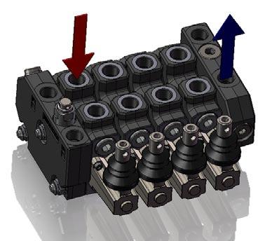
10 SM - Section Module POS. DESCRIPTION Code 1 Section Body SM 2 Load Holding Check Valve - 3 Spool Control A-side Page 14 4 Spool Control B-side Page 14 5 Secondary Valve A-side Page 16 6 Secondary Valve B-side Page 16 7 Main Spool Page 13 TECHNICAL DATA Maximum Port Flow 90 l/min 24 USGpm Maximum Working Pressure 350 bar 5000 psi Port Size A/B alt 2 BSP G1/2 SAE #10 M22x1,5 Module Weight 3,0 kg 6,6 lbs MODULE DESCRIPTION Manual Section Module which can be used together with any of the inlet modules. The SM-section can be equipped with secondary valves on the A- and B-port such as shock relief and/or anticavitation valves (5) & (6). It has a load holding check valve for each port (2) and can be equipped with manual hand lever operation or wire control. A wide range of spool positioning controls are also available with spring centring or detents in various positions of the spool stroke. 10

11 SPO Section Module with PO Check Valves POS. DESCRIPTION Code 1 Section Body SPO 2 Load Holding Check Valve - 3 Spool Control A-side Page 14 4 Spool Control B-side Page 14 5 Pilot Operated Check Valve A-Side - 6 Pilot Operated Check Valve B-Side - 7 Main Spool Page 13 TECHNICAL DATA Maximum Port Flow 90 l/min 24 USGpm Maximum Working Pressure 350 bar 5000 psi Port Size A/B alt 2 BSP G1/2 SAE #10 M22x1,5 Module Weight 3,6 kg 7,9 lbs MODULE DESCRIPTION Manual Section Module which can be used together with any of the inlet modules. It has built in pilot operated check valves (5) & (6) for applications where a zero leakage is required when the spool is in neutral position. It has a load holding check valve for each port (2) and can be equipped with manual hand lever operation or wire control. A wide range of spool positioning controls are also available with spring centring or detents in various positions of the spool stroke. 11

12 OM -Outlet Module POS. DESCRIPTION Code 1 Outlet Body OM 2 Plug - 3 Plug - TECHNICAL DATA Maximum Outlet Flow 90 l/min 24 USGpm Maximum Working Pressure 350 bar 5000 psi Port Size T2 BSP G1/2 SAE #10 M22x1,5 Port Size T3 BSP G1/2 SAE #10 M22x1,5 Module Weight 4.2 kg 9,3 lbs MODULE DESCRIPTION Outlet Module which can be equipped with High-Pressure-Carry-Over by plugging (2) and (3) with special cavity blanking plugs. 12


13 Spools All of NIMCO s spools are designed for specific flow rates in order to achieve optimal load control characteristics and to fully utilise the entire stroke of the spool. By optimizing the balance between spools and valve housing, spring forces are minimized and exact manoeuvring is achieved. Besides the standard spools listed there are also special spools available. For further information concerning these types please contact your NIMCO representative. Standard Spools Spool Type Symbol Spool Code Double Acting 3S Single Acting A-port 2SA Single Acting B-port 2SB Double Acting with 4th pos Float 4S Motor 4S 13


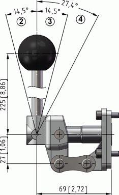
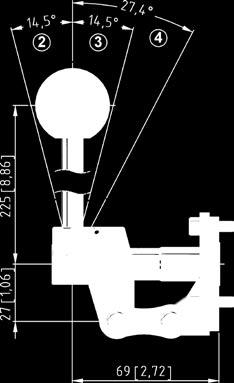
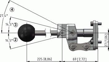
14 Spool Controls Type A-Side B-Side Type 9 Spring Centred Open Spool End OE 9S Spring Centred with Through Spool 10 Detent in pos 1, 2, 3 10S Detent in pos 1, 2, 3 with Through Spool Hand Lever Linkage Vertical S1 11 Spring Centred Detent in pos 4 13 Spring Centred Detent in pos 2 Hand Lever, Linkage Horizontal S2 14 Spring Centred Detent in pos


15 Spool Controls Code Type A-Side B-Side Type Code 16 Detent in pos 1, 2, 3 & 4 Enclosed Hand Lever S5 17 Detent in pos 2 & 3 P Pneumatic ON/OFF Hand Lever Linkage Vertical Opposite Spool Movement S7 PP Pneumatic Proportional EP Electro Pneumatic ON/OFF Mechanical Joystick for Dual Spool Control S6 HP Hydraulic Proportional Hydraulic Proportional HP 15
![Secondary Port Valves C Shock Relief Valve Differential operated shock relief valve for preventing pressure peaks. Fixed pressure setting from 35 to 320 bar [500-4650 psi].](/docs-images/86/94900784/images/16-0.jpg "CA Shock Relief and Anti Cavitation Valve Differential operated shock relief valve for preventing pressure peaks in combination with a check valve to prevent negative pressure in the work ports.")
16 Secondary Port Valves C Shock Relief Valve Differential operated shock relief valve for preventing pressure peaks. Fixed pressure setting from 35 to 320 bar [ psi]. CA Shock Relief and Anti Cavitation Valve Differential operated shock relief valve for preventing pressure peaks in combination with a check valve to prevent negative pressure in the work ports. Fixed pressure setting from 35 to 320 bar [ psi]. Anti-cavitation valve Check valve for preventing negative pressure in the work ports. P Cavity Blanking Plug The plug is used when a work port accessory valve cavity should be blanked off. 16

17 Accessory Valves UCV08 - Unload Control Valve The UCV08 valve is used in the IM inlet module as an emergency stop feature. It can also be used to unload the standby pressure for energy saving and lower heat generation when no hydraulic functions are used. Hydraulic Data Maximum Operating Pressure 345 bar [5000 psi] Rated Flow 40 l/min Internal Leakage Max ccm/min at 345 bar [5000 psi] Contamination Level 20/18/15 acc. ISO 4406 Temperature Range -40 to +120ºC Electrical Data Power 345 bar [5000psi] Voltage 12 V 24 V Current 1.22 A 0.61 A Resistance 9.8 Ω ±5% 39.3 Ω ±5% Connector Type DIN Protection Class IP65 Electrical data Ordering Code UCV- 12- NC- X 12 V V 24 Normally Open NO Normally Closed NC Manual Override M None X PERFORMANCE PRESSURE DROP bar/psi 8.6/ / /75 3.4/50 1.7/25 to de-energized to energized cst/150 sus oil at 40 C FLOW lpm/gpm

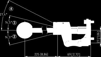
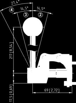
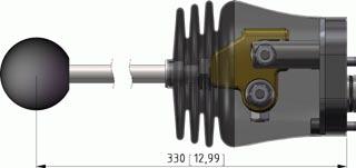
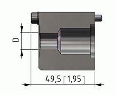
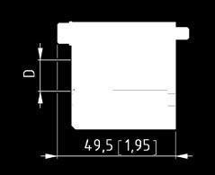
18 Dimensional Drawing 18

19 Ordering Code Enter option codes in the empty fields for desired inlet module, leave the rest blank Inlet Module IM IE IF Electrical Unloading Valve (UCV) * 12 VDC 12 * 24 VDC 24 ** Unloading when no signal to UCV NO ** Unloading when no signal to UCV + Man. Override NO-M ** Unloading when signal to UCV NC ** Unloading when signal to UCV + Man. Override NC-M ** None P Main Relief Valve * Main Relief Valve RV * Plug P ** Pressure Setting bar [psi] Threads BSP Metric SAE G M S * * * * * * Section No Section Module * Manual Section SM * Section with Pilot Operated Check Valves SPO * Mid Inlet Module IM1 - Parallel Circuit IM1 * Mid Inlet Module IM2 - Dual Circuit IM2 * Mid Inlet Module IM3 -Tandem Circuit IM3 ** Pressure Relief Valve for Mid Inlet Module RV+pressure setting bar [psi] **Plug P Spool Code See page 13 Spool Control A-Side Spring Centered 9 Detent in pos 1, 2 & 3 10 Spring Centered Detent in pos 4 11 Spring Centered Pressure Point in pos 5 18 El. Hyd. Proportional Hyd. Proportional Spool Control B-Side Manual hand lever Wire Control El. Hyd. Proportional w/ manual hand lever El. Hyd. Proportional Hyd. Proportional w/ manual hand lever Hyd. Proportional Secondary Valves A-side Shock/Anticav-valve Shock valve Antacav. Valve None Secondary Valves B-side Shock/Anticav-Valve Shock valve Antacav. Valve None Threads BSP Metric SAE EHP HP S5 W EHL EHO HPL HPO CA+pressure setting in bar [psi] C+pressure setting in bar [psi] A P CA+pressure setting in bar [psi] C+pressure setting in bar [psi] A P G M S ** ** ** ** ** ** Enter option codes in the empty fields for each individual section of the valve up to the desired number of sections, leave the rest blank If a mid inlet should be used, fill the code for the desired mid inlet module and the relief valve on the position it should be located and leave the other fields in that column blank * * * * * * * * * * ** ** ** ** ** ** ** ** ** ** Outlet Module High-Pressure-Carry-Over High-Pressure-Carry-Over None Threads BSP Metric SAE HPCO P G M S OM 19
20 Notes 20
21 Notes 21
22 Notes 22
23

24 Directional Control Valve CV550 Smart Solutions... for the Future Nimco AB Agnesfridsvägen 186 SE Malmö Sweden Rev
Contents. Directional Control Valve 2 Series CV Unibody. Page 3-4. General Information. Page 5. Technical data. Page 6. Performance Curves
 Contents Page 3-4 Page 5 Page 6 Page 7 Page 8 Page 9 Page 10 Page 11-12 Page 13 Page 14 Page 15 General Information Technical data Performance Curves Dimensions - Basic Valve Dimensions - Unibody Secondary
Contents. Directional Control Valve 2 Series CV 300
 Contents Page 3 General Information Page 4 Technical data Page 5 Dimensions Page 6 Secondary Valves Page 7 Cylinder port mounted secondary valves Page8 Spool - Control characteristics Page 9-10 Spool Controls
Contents. Directional Control Valve 3 Series CV 452. Page 3-4. General Information. Page 5. Technical data. Page 6. Performance Curves.
 Contents Page 3-4 Page 5 Page 6 Page 7 Page 8 Page 9 Page 10 Page 11 Page 12 Page 13 Page 14 General Information Technical data Performance Curves Dimensions - Basics Valve Dimensions - LS Valve Secondary
Post-Compensated Proportional Valve CV2000LS
 www.nimco-controls.com Post-Compensated Proportional Valve CV2000LS Smart Solutions... for the Future Contents Page 5 Page 6 Page 7 Page 8 Page 9 Page 10 Page 11 Page 12 Page 13 Page 14 Page 15 Page 16
Monobloc and Sectional Directional Control Valves
 Monobloc and Sectional Directional Control Valves motion and progress 1/220 6 Monobloc directional control valves Contents 6.1 General specifications 66 6.2 Dimensional data 67 6.3 Performances curves
Sectional Directional Control Valve RSQ 240
 Sectional Directional Control Valve RSQ 0 Key valve features RSQ 0 is a sectional open center valve, designed for max. operating pressures up to 50 bar and max. pump flows up to 00 l/min. It is available
Available manual, pneumatic, and hydraulic spool control kits.
 Fitted with a main pressure relief valve and a load check valve on every working section. Available with parallel circuit. Optional carry-over Variety of port valves (auxiliary valves) Available manual,
Commercial Shearing (Pty) Ltd THE WORLDWIDE PROGRAM OF VALVES ISO 9001
 Ltd THE WORLDWIDE PROGRAM OF VALVES ISO 9001") Commercial Shearing (Pty) Ltd THE WORLDWIDE PROGRAM OF VALVES ISO 9001 An Insight into Valve Technology CLEAN ROOM ASSEMBLY AND TEST A major investment has been made in a clean-room assembly and test environment.
Commercial Shearing (Pty) Ltd THE WORLDWIDE PROGRAM OF VALVES ISO 9001 An Insight into Valve Technology CLEAN ROOM ASSEMBLY AND TEST A major investment has been made in a clean-room assembly and test environment.
Auxiliary valves. Lever. Spool positioner Check valve Spool
 Auxiliary valves Lever Spool positioner Check valve Spool CONTENTS: Page -Technical data... 1 -Dimensions RP80... 2 -Dimensions RP60... 3 -Lever mechanism... 4 -Spools/spool control... 5 -Inlet cover/outlet
Directional Control Valve Equipment for Front End Loaders
 Directional Control Valve Equipment for Front End Loaders CONTENT nimco Page 3 General Information Page 4 Page 5 Page 7 Page 11 Page 12 Technical Data Application Example System Options Quickview Flow
Directional control valve / RM 270
 Directional control valve / 31-02-RM270-05 Nordhydraulic AB P.O Box 189 (Industrivägen 15) SE-872 24 KRAMFORS Sweden Solutions that power your visions Telephone: Int. +46 612 71 72 00 Telefax: Int. +46
-Technical data... 2/14 -Circuit mode... 2/14 -Dimensions RP /14
 Auxiliary valves Document: SCV-1-June 2013 Lever Spool positioner Check valve Spool CONTENTS: Page -Technical data... 2/14 -Circuit mode... 2/14 -Dimensions... 3/14 -Dimensions... 4/14 -Lever mechanism...
Contents. Directional Control Valve 2 Series EPCV 452. Page 3. General Information. Page 4-5. Technical data. Page 6. Performance Curves.
 Contents Page 3 Page 4-5 Page 6 Page 7 Page 8 Page 9 General Information Technical data Performance Curves Dimensions : Hydraulic Valve and Accumulator Hydraulic Schematics Order Code Directional Control
Page 3 Page 4 Page 6 Page 8 Page 9 Page 10 Page 11
 Contents Page 3 Page 4 Page 6 Page 8 Page 9 Page 10 Page 11 General Information Compact Loader Valves Medium Size Loader Valves Large Size Loader Valves 3rd, 4th and 5th Function Valves Cable Joystick
Sectional Directional Control Valve RS 220
 Sectional Directional Control Valve RS 0 RS 0 is a sectional open center valve designed for max. operating pressures up to 00 bar and max. pump flows up to 0 l/min. Technical data Pressure and flow values*
SECTIONAL DIRECTIONAL VALVE HDS 20 SERIES. CROSS HYDRAULICS PTY LTD YELLOW CATALOGUE Page 3.84
 CROSS HYDRAULICS PTY LTD YELLOW CATALOGUE Page 3.84 Material specification: Standard features: Optional features available: Symbols: P T A/B H.P.C.O. RV P 1 T 1 Weight CROSS HYDRAULICS PTY LTD YELLOW CATALOGUE
MONOBLOCK DIRECTIONAL CONTROL VALVES
 MONOBLOCK DIRECTIONAL CONTROL VALVES CONTENTS: RM0...... RM5...... RM40P...... RM80...... RMD90...... MRP70... Page 1/19&/19 /19...5/19 6/19...10/19 11/19...15/19 16/19&17/19 18/19&19/19 MONOBLOCK DIRECTIONAL
V050 SERIES DIRECTIONAL CONTROL VALVE
 V5 SERIES DIRECTIONAL CONTROL VALVE TAKE CONTROL Take control with Muncie Power Products V5 directional control valve. The V5 is constructed with high-grade iron castings and nickel-plated spools for use
V250 SERIES DIRECTIONAL CONTROL VALVES
 V SERIES DIRECTIONAL CONTROL VALVES TAKE CONTROL OF YOUR HYDRAULICS Take control with Muncie Power Products V directional control valve. The V is constructed with high-grade iron castings and nickel-plated
Monobloc and Sectional Directional Control Valves
 Monobloc and Sectional Directional Control Valves 200 P 991210 E 03 / 10.04 1/220 2 Monobloc directional control valves HDM140 Contents 2.1 General specifications 9 2.2 Dimensional data 10 2.3 Performances
HYDRAULICS VINCKE DIRECTIONAL CONTROL VALVES
 VINCKE DIRECTIONAL CONTROL VALVES TECH-DCV200.1 index 3 link to your page / link a su página Monoblock hydraulic distributors Monoblock hydraulic distributors 35 liters 3 P35 Monoblock hydraulic directional
ORV-M45. Contents. Additional Informations
 Contents Working Conditions 3 Dimensional Data 4 Hydraulic Circuit 5 Performance Data And Curve 7 Inlet Relief Options 8 Ordering Codes 9 Spool Options 11 Spool Positioners Side of Return 14 Spool Positioners
SECTIONAL DIRECTIONAL VALVE HDS 30 SERIES. CROSS HYDRAULICS PTY LTD YELLOW CATALOGUE Page 3.106
 CROSS HYDRAULICS PY LD YELLOW CAALOGUE Page 3.106 Material specification: Standard features: Optional features available: Symbols: P A/B H.P.C.O. RV P 1 1 Weight CROSS HYDRAULICS PY LD YELLOW CAALOGUE
Monoblock Directional Control Valve RM 230
 Monoblock Directional Control Valve RM 230 Key valve features RM 230 light is a monoblock valve, designed for max. operating pressures up to 3,000 psi (210 bar) and typ. pump flows up to 20 gpm (70 Lpm).
4-Way Directional Control With Pressure Compensated Flow Control PSDCF120M64LF Specifications:
 Engineering & Manufacturing Solutions With Pressure Compensated Flow Control Specifications: Rated for 0-18 gpm (0-68.1 lpm) Rated for 3000 psi (207 bar) Weighs 6-1/2 lbs. (2.9 kg) 30 Micron filtration
SECTION A FRONT END LOADER VALVES
 NB: models, Codes and Specifications may be subject to change without notice. SECTION A FRONT END LOADER VALVES Valve Series Nominal PAGE WALVOIL FRONT-END LOADER VALVES SDM102 Series... 45L/Min... A 14
COMPACT CATALOGUE SECTIONAL DIRECTIONAL CONTROL VALVES
 COMAC CAALOGUE SECIONAL DIRECIONAL CONROL VALVES SDS5 Features Simple, compact and heavy duty designed sectional valve from to sections for open and closed centre hydraulic systems. H Fitted with a main
Monoblock Directional Control Valve PMB22TSTSAB PMB23TSTSTSLB PMB21TDLB
 Engineering & Manufacturing Solutions Specifications: FLOW RATINGS: - MB21 & MB22 10 gpm (38 lpm) - MB23 8 gpm (30 lpm) Rated up to 4000 psi (275 bar). Port Sizes: - Inlet/Outlet #8 SAE. -Work Ports #8
Monobloc and Sectional Directional Control Valves
 Monobloc and Sectional Directional Control Valves motion and progress 1/220 10 Sectional directional control valves HDS20 Contents 10.1 General specifications 177 10.2 Dimensional data 178 10.3 erformances
Flow sharing control block in mono block / sandwich plate design M6-22
 Flow sharing control block in mono block / sandwich plate design M6-22 RE 64322 Edition: 01.2015 Replaces: 05.2012 Size 22 Series 3X Maximum operating pressure on pump side 350 bar on consumer side 420
COMPACT CATALOGUE SECTIONAL DIRECTIONAL CONTROL VALVES
 COMAC CAALOGUE SECIONAL DIRECIONAL CONROL VALVES Features Simple, compact and heavy duty designed sectional valve from to sections for open and closed centre hydraulic systems. H Fitted with a main pressure
NV452 Monoblock directional control valve
 NV452 Monoblock directional control valve Product Features General Specifications Order Coding Open Center Load Sense Performance Data Inlet Options Spool Positioners Spool Options Auxilary Valves Lever
Monobloc and Sectional Directional Control Valves
 Monobloc and Sectional Directional Control Valves 200--991210-N-03/09.2015 03 / 10.04 1/220 11 Sectional directional control valves HDS30 Contents 11.1 General specifications 197 11.2 Dimensional data
V5 60 LPM SECTIONAL SPOOL VALVE
 V5 60 LPM SECTIONAL SPOOL VALVE 37 V5 60 LPM SECTIONAL SPOOL VALVE Description A low profile sectional spool valve, lever, solenoid or cable operated. Suitable for open or closed centre circuits. Spool
Flow sharing control block in mono block / sandwich plate design M6-15
 Flow sharing control block in mono block / sandwich plate design M6-15 RE 64321 Edition: 01.2015 Replaces: 05.2012 Size 15 Series 3X Maximum operating pressure on pump side 350 bar on consumer side 420
DC Series. 4-Way Directional Control Valve With Or Without Flow Control PDC16T4PBS PDCF16TM454LF
 Engineering & Manufacturing Solutions Specifications: Rated for 0-45 gpm (0-170 lpm) Rated for 3000 psi (207 bar) Std. port sizes (Consult factory for others) - 3/4 NPT all ports - #16 SAE (1-5/16-12)
4-Way Directional Control Valve With Hydraulic Kick Out
 Engineering & Manufacturing Solutions 4-Way Directional Control Valve With Hydraulic Kick Out Specifications: Rated for 0-18 gpm (0-68.1 lpm) Rated for 3000 psi (207 bar) Weighs 5-1/2 lbs. (2.5 kg) 30
Modular Unit 6MB HYDRANOR MODULAR UNIT 6MB GENERAL DESCRIPTION. 6MB-200-**-2C General Arrangement. Rev
 MODULAR UNIT 6MB GENERAL DESCRIPTION Figure 1 6MB-200-**-2C General Arrangement Rev. 5 5.1.1 Figure 2 General Arrangement 6MB-650-**-2C The Modular Units 6 MB is a complete unit for controlling of hydraulically
SECTIONAL BODY. Model SV. Directional Control Valves VALVES STANDARD FEATURES SPECIFICATIONS. Parallel or Series Circuit Construction ...
 Directional Control Valves SECTIONAL BODY Model SV STANDARD FEATURES SPECIFICATIONS Parallel or Series Circuit Construction Foot Mounting Pressure Rating Maximum Operating Temp....... Weight Per Section......
PVG 32 Proportional Valve Group
 Technical Information PVG 32 Proportional Valve Group www.danfoss.com Revision history Table of revisions Date Changed Rev December 218 Major revision of document. 111 September 218 Safety topic, new PVBS
Directional Control Valve. Formerly the RSM290 Series. Technical data. Pressures / Flows Max. operating pressure set per port:
 X-Series Directional Control Valve DX- Formerly the RSM90 Series DX- is a sectional valve designed for max. operating pressures up to 000 psi (0 bar) and max. pump flows up to 80 l/min with Q-inlet. For
HYDRAULIC CONTROL VALVES
 HYDRAULIC VALVES SECTION 3A HYDRAULIC CONTROL VALVES MONOBLOCK DIRECTIONAL CONTROL VALVES...71 SLICE DIRECTIONAL CONTROL VALVES...73 HANDLEVERS...76 S additions for valves...76 VALVE CONTROL KITS additions
CLS180 Proportional Load Sensing Mobile Valve
 Mobile valves Proportional Load Sensing, Model CLS180 350 bar 180 L/min Up to 10 sections Eaton Pro-FX TM Ready CLS180 Proportional Load Sensing Mobile Valve Overhaul manual / Trouble shooting guide Contents
TPV Variable Displacement Closed Loop System Axial Piston Pump HY-TRANS THE PRODUCTION LINE OF HANSA-TMP HT 16 / M / 501 / 1009 / E
 HYDRAULIC COMPONENTS HYDROSTATIC TRANSMISSIONS GEARBOXES - ACCESSORIES HY-TRANS THE PRODUCTION LINE OF HANSA-TMP Via M. L. King, 6-41122 MODENA (ITALY) Tel: +39 059 415 711 Fax: +39 059 415 729 / 059 415
Selector Valve RV 713
 Selector Valve RV 713 Key valve features RV 713 is a 3 way selector valve designed for flows up to 42gpm (160 Lpm) and max. operating pressures up to 3,625 psi (250 bar). Spools, both 2 and 3 position,
HYDRAULIC MOTORS MLHH
 HYDRAULIC APPLICATION» Conveyors» Feeding mechanism of robots and manipulators» Metal working machines» Textile machines» Machines for agriculture» Food industries» Mining machinery etc. CONTENTS Specification
Hydraulic Pump Series VP1 Variable Displacement
 Variable Displacement Catalog 9129 8222-02 February 1999, GB Content Page General information 3 Design 3 Specifications 4 Ordering information 4 VP1 cross section 4 Installation dimensions 5 Line dimensioning
Monoblock directional control valves DL - Directional control valve
 Monoblock directional control valves DL - Directional control valve DL Before use, carefully read the GENERAL INSRUCIONS FOR USE OF DIRECIONAL CONROL VALVES 398SMD008I00-06-2-208 DL echnical data Nominal
Hydro M t HYDRAULIC VALVES SN-4.
 Hydro HYDRAULI VALVES A SRONG OMMIMEN O QUALIY Our concept is to sell and deliver the best quality of hydraulic valves, that fully meet our customer s rigorous requirements! o this end, our quality control
VINCKE HYDRAULIC PUMPS
 : VNK BA10VS 21 Variable displacement axial piston pump of swashplate design for hydraulic open circuit systems. Flow is proportional to drive speed and displacement. It can be infinitely varied by adjustment
60VSERIES PFD-30 MSV-16 RV-30, RV-60. Muncie Power Products MP95-08 (Rev. 5-05) Printed in the U.S.A. Muncie Power Products, Inc VALVE WARRANTY
 Printed in the U.S.A. Muncie Power Products, Inc VALVE WARRANTY") VALVE WARRANTY The Muncie 60V Series Valve is warranted against any defect in material and workmanship which existed at the time of sale by Muncie, according to the following provisions, subject to the
VALVE WARRANTY The Muncie 60V Series Valve is warranted against any defect in material and workmanship which existed at the time of sale by Muncie, according to the following provisions, subject to the
Hydraulics CONTROL VALVES
 Hydraulics CONTROL VALVES PRODUCT INDEX Series Page Series Page Series Page 90 Rotating Couplings 12 In Line Double-acting flow control 17 and shut-off control needle valves Directional Control Valves
CABLE TIPPING VALVE. Tipping valve type Order code IN TANK OUT Weight HYDRAULICS VALVES 2.2 FM-45 CE G 1/2 G 1/2 G 1/2.
 CABLE TIPPING VALVE Optional Mechanical tipping valve operated by cable controls series LINEA or LINEA BLOCK to suit light duty tipper trucks. Open centre hydraulic scheme according to CE standards. -
Mobile Directional Valve. Product Catalog MDG for Mobile Equipment Flows to 60 I/min (15.8 USgpm)
") Mobile Directional Valve Product Catalog MDG for Mobile Equipment Flows to 60 I/min (15.8 USgpm) Table of Contents General Information...3 Model code Valve Section...4 Valve Assembly...5 Spool Data...6
Mobile Directional Valve Product Catalog MDG for Mobile Equipment Flows to 60 I/min (15.8 USgpm) Table of Contents General Information...3 Model code Valve Section...4 Valve Assembly...5 Spool Data...6
Check valves Direct and pilot operated check valve functions for applications up to 350 bar (5000 psi) and 227 L/min (60 USgpm)
 and 227 L/min (60 USgpm)") Hydraulic Screw-in Cartridge Valves (SiCV) Check valves Direct and pilot operated check valve functions for applications up to 5 bar (5 psi) and 7 L/min (6 USgpm) Check valves CHECK VALVES... -4 FPR -
Hydraulic Screw-in Cartridge Valves (SiCV) Check valves Direct and pilot operated check valve functions for applications up to 5 bar (5 psi) and 7 L/min (6 USgpm) Check valves CHECK VALVES... -4 FPR -
CLS100 Proportional Load Sensing Mobile Valve
 Mobile Valves Proportional - Load Sensing Model CLS100 350 bar 100 L/min Up to 10 sections Eaton Pro-FX TM Compliant CLS100 Proportional Load Sensing Mobile Valve Overhaul manual / Trouble shooting guide
Pilot Operated Pressure Relief Valve Series R5V (Denison)
") Characteristics Pilot operated pressure relief valves series R5V have a similar design to the subplate mounted R4V series. The SAE flanges allow to mount the valves directly on the outlet flanges of pumps
Characteristics Pilot operated pressure relief valves series R5V have a similar design to the subplate mounted R4V series. The SAE flanges allow to mount the valves directly on the outlet flanges of pumps
MDT. Monoblock directional control valves MDT - Directional control valve
 Monoblock directional control valves - Directional control valve efore use, carefully read the GENERL INSRUCIONS FOR USE OF DIRECIONL CONROL VLVES echnical data Nominal flow 35 l/min 9. US gpm Nominal
LUDV control block in mono block/sandwich plate design M7-20
 LUDV control block in mono block/sandwich plate design M7-20 RE 64293 Edition: 06.2013 Replaces:. Size 20 Series 3X Maximum operating pressure On the pump side 380 bar On the actuator side 420 bar Maximum
Open center control block in mono block design MO-16, 22, 32
 Open center control block in mono block design MO-,, 3 RE 35 Edition: 0.0 Replaces: 0.003 Sizes,, 3 Series X Maximum working pressure on the pump side 350 bar on the consumer side 0 bar Maximum flow MO-:
Proportional Directional Valve System
 roportional Directional Valve System in Sectional Design Reference: 31--9589-ENG-2 Issue: 8.215 1/2 Contents age 1 General... 3 1.1 Description... 3 1.2 pplication examples... 3 2 Technical data... 3 3
LOAD SENSE SECTIONS. Series 20. Directional Control Valves NEED NEW PIC VALVES STANDARD FEATURES SPECIFICATIONS
 Directional Control Valves LOAD SENSE SECTIONS NEED NEW PIC Series 20 STANDARD FEATURES Control and reduced Dead Band (20I) and Tie Rod Kits SPECIFICATIONS Pressure Rating Foot Mounting Maximum Operating
MP18/SIC & SIO Stacking Valve System Technical Information Manual
 Electric Drives and Controls Hydraulics Linear Motion and Assembly Technologies Pneumatics Service MP18/SIC & SIO Stacking Valve System Technical Information Manual The Drive & Control Company Copyright
LUDV control block of sandwich plate design
 LUDV control block of sandwich plate design RE 64125/02.11 Replaces: 01.10 1/22 ype SX 14, SX 14 S Nominal size 14 Series 2X Maximum pressure, pump side 250 bar Maximum pressure, actuator side 300 bar
Flow sharing control block in sandwich plate design M7-25
 Flow sharing control block in sandwich plate design M7-25 RE 64297 Edition: 07.2016 Replaces: 06.2012 Size 25 Series 3X Maximum working pressure on the pump side 380 bar on the consumer side 420 bar Maximum
» Feeding mechanism of robots and manipulators» Metal working machines» Textile machines» Machines for agriculture» Food industries
 HYDRAULIC RW APPLICATION» Conveyors» Feeding mechanism of robots and manipulators» Metal working machines» Textile machines» Machines for agriculture» Food industries» Grass cutting machinery etc. CONTENTS
Control block EDD Modular Directional Valve
 Control block EDD Modular Directional Valve 2 Control block EDD Modular Directional Valve Bosch Rexroth Oil Control S.p.A. introduces the EDD size 08 directional control valve with up to 80 l/min to the
HYDRAULICS VINCKE HYDRAULIC PUMPS
 VINCKE HYDRAULIC PUMPS TECH-VHP200.1 index 3 link to your page / link a su página Gear pumps Introduction 3 Group 0 3 Group 1 3 Group 2 3 Group 3 4 6 7 12 18 Variable displacement pumps 21 Hand pumps 3
BW0511FP. ByWire Elements BW0511FP Flow Sharing Element Interface IBW0511
 ywire Elements Flow Sharing Element Interface IW05 efore use, carefully read the GENERL INSTRUCTIONS FOR USE OF DIRECTIONL CONTROL VLVES Technical data Nominal flow Nominal pressure 35 l/min - P=8 bar
Hydraulics. Axial Piston Pumps Series PVP. Introduction. With thru shaft option for multiple pump options Swash plate type for open circuit
 Introduction *not included Pump with standard compensator, code: "omit" With thru shaft option for multiple pump options Swash plate type for open circuit Pump with load sensing, code: "A" Mounting style
Truck Hydraulics. Serie VP1 Variable Displacement Pumps
 ruck Hydraulics Variable Displacement Pumps aerospace climate control electromechanical filtration fluid & gas handling hydraulics pneumatics process control sealing & shielding Contents Pump and line
Monobloc and Sectional Directional Control Valves
 Monobloc and Sectional irectional Control Valves 200 - - 991210 - - 03/09.2015 1/220 8 Sectional directional control valves HS11 8 valves... p.101 Contents 8.1 General specification 101 8.2 imensional
TPV Variable Displacement Closed Loop System Axial Piston Pump THE PRODUCTION LINE OF HANSA-TMP HT 16 / M / 852 / 0815 / E
 HYDRAULIC COMPONENTS HYDROSTATIC TRANSMISSIONS GEARBOXES - ACCESSORIES Certified Company ISO 9001-14001 ISO 9001 Via M. L. King, 6-41122 MODENA (ITALY) Tel: +39 059 415 711 Fax: +39 059 415 729 / 059 415
Series 34. Sectional Directional Control Valve Specifications: P34A Engineering & Manufacturing Solutions
 Engineering & Manufacturing Solutions Specifications: 12 gpm (45.4 lpm) Nominal Capacity (see flow chart). 3500 psi (241 bar). 400 psi (27 bar) max tank pressure. 12 sections max (consult factory for more).
Proportional Valves. Proportional solenoid valves for pressure and flow control B-1.A. An Eaton Brand
 Proportional Valves Proportional solenoid valves for pressure and flow control An Eaton rand -.A Proportional Valves Valve Locator/Section Contents Note: Proportional valve solenoid coils and electronic
TPV Variable Displacement Closed Loop System Axial Piston Pump THE PRODUCTION LINE OF HANSA-TMP HT 16 / M / 851 / 0813 / E
 HYDRAULIC COMPONENTS HYDROSTATIC TRANSMISSIONS GEARBOXES - ACCESSORIES THE PRODUCTION LINE OF HANSA-TMP Variable Displacement Closed Loop System CONTENTS General Information... Order Code... Manual Control
IGP /117 ED INTERNAL GEAR PUMPS SERIES 10 OPERATING PRINCIPLE TECHNICAL SPECIFICATIONS HYDRAULIC SYMBOL
 00/7 ED IGP INTERNAL GEAR PUMPS OPERATING PRINCIPLE IGP pumps are volumetric displacement pumps with internal gears, available in five sizes, each divided into a range of different displacement. The pumps
GPM PSI LPM BAR MODEL CAVITY PAGE IF-S3A special IF-S3D special IG-S4A special 198
 Transmission & Brake Spool Valves Screw-in style GPM PSI LPM BAR MODEL CAVITY PAGE 2 1000 8 70 TC-S3A 5/8-18 186 6 1000 23 70 TF-S3A 7/8-14 188 6 1000 23 70 TF-S3D 7/8-14 190 5 1000 20 70 TG-S4A 7/8-14
Vickers Pressure Relief Solenoid Operated, Two-Stage Directional Control Valve DG5S4-02 Flows to 115 l/min (30 USgpm) Pressure to 210 bar (3000 psi)
 Pressure to 210 bar (3000 psi)") Vickers Pressure Relief Solenoid Operated, Two-Stage Directional Control Valve DG5S4-02 Flows to 115 l/min (30 USgpm) Pressure to 210 bar (3000 psi) Revised 2/93 GB C 2037 Table of Contents Model Code...................................................................................................
Vickers Pressure Relief Solenoid Operated, Two-Stage Directional Control Valve DG5S4-02 Flows to 115 l/min (30 USgpm) Pressure to 210 bar (3000 psi) Revised 2/93 GB C 2037 Table of Contents Model Code...................................................................................................
Solutions. ydraulics. We Manufacture. H y d r a u l i c s. Eaton Directional Control Valves. h y d r a u l i c s. Models and 31930
 H y d r a u l i c s ydraulics Eaton Directional Control Valves h y d r a u l i c s Models 319 and 3193 with Pilot Operated Checks We Manufacture No. 11-5 March 1996 Solutions Directional Control Valves
20 to 150 mm 2-Way Automatic Flow Balancing Control Ball Valves
 VFB30 Series Issue Date February 1, 2016 20 to 150 mm 2-Way Automatic Flow Balancing Control Ball Valves Low Torque Facilitates the use of smaller, less expensive directmount rotary-motion actuators Extends
General Specifications DRV DRV-Exm DRV-Exd
 direct operated, 3-way pressure reducing valve Q max = 8 l/min pressure range = - 5 bar body stainless steel (optional) Description The proportional pressure reducing valve (3-way function) is used to
Gear Pumps / Motors. Series PGP / PGM Fixed Displacement Pumps, Cast-Iron and Aluminium Designs
 Gear Pumps / Motors Series PGP / PGM Fixed Displacement Pumps, Cast-Iron and Aluminium Designs Table of contents Heavy-duty Pumps and Motors Series PGP, PGM Contents Page Series 500 Aluminium Table of
Large Electronically Adjustable Proportional Pressure Compensated Flow Control Engineering & Manufacturing Solutions
 Engineering & Manufacturing Solutions LEFC Specifications: See flow chart for capacity. Max. 3000 psi cartridge input pressure. Nominally Rated for 3000 psi (207 bar). Tank Port - #4 SAE (10 psi (0.69
SDS400. Sectional directional control valve
 SDS4 Sectional directional control valve SDS4 Features Sectional directional control valve for high flow, available for fixed displacements hydraulic pumps. From to work sections Open centre Optional carry-over
PLP Pump (up to 16 cm 3 /r max. 120 bar) PHV Pump (up to 32 cm 3 /r max. 250 bar) PVS Pump (up to 100 cm 3 /r max. 100 bar)
 PHV Pump (up to 32 cm 3 /r max. 250 bar) PVS Pump (up to 100 cm 3 /r max. 100 bar)") General Catalogue MODEL PLP Pump (up to 16 cm 3 /r max. 120 bar) PHV Pump (up to 32 cm 3 /r max. 250 bar) PVS Pump (up to 100 cm 3 /r max. 100 bar) PSP Pump (up to 100 cm 3 /r max. 160 bar) PSPK Pump (up
General Catalogue MODEL PLP Pump (up to 16 cm 3 /r max. 120 bar) PHV Pump (up to 32 cm 3 /r max. 250 bar) PVS Pump (up to 100 cm 3 /r max. 100 bar) PSP Pump (up to 100 cm 3 /r max. 160 bar) PSPK Pump (up
90VSERIES DIRECTIONAL CONTROL VALVE MSV-16 RV-30, RV-60 PFD-30
 MP95-09.90VSerValve.qxp:*MP95-09.90VSerValve v5 8/11/08 10:27 AM Page 12 VALVE WARRANTY The Muncie 90V Series Valve is warranted against any defect in material and workmanship which existed at the time
NB: models, Codes and Specifications may be subject to change without notice. SECTION A DIRECTIONAL CONTROL VALVES MANUAL DIRECTIONAL VALVES
 NB: models, Codes and Specifications may be subject to change without notice. SECTION A DIRECTIONAL CONTROL VALVES MANUAL DIRECTIONAL VALVES Valve Series Page...... A 2 WALVOIL FRONT-END LOADER VALVES...
Flow Control Valve. 1 Description. 2 Symbols. Series SRCA General. 1.2 Application examples way flow control way flow control
 Flow Control Valve Series SRC.. plug-in coil for easy coil change flow rates are unaffected by changes in temperature or load compact design reduced p ZnNi coating (>70h DIN EN ISO 97 NSS) Description.
Mobile Valves Proportional - Load Sensing
 Mobile Valves Proportional - Load Sensing Model CML60 325 bar 60 L/min Up to 8 sections Eaton F(x) Compliant Table of Contents General Information... 3 Model Code Valve Section... 4 Valve Assembly... 5
STANDARD FEATURES. Flow Control Inlet
 Directional Control Valves SECTIONAL BODY Model SV STANDARD FEATURES -0 Sections Per Valve Bank Differential Poppet Style Relief, Adjustable Load Checks On Each Section from 500 to 3000 psi (Also available
油力油壓工業股份有限公司 YOULI HYDRAULIC INDUSTRIAL CO.,LTD. ISO 9001:2008 QA100189
 ISO 9001:2008 Q100189 油力油壓工業股份有限公司 YOULI HYDRULIC INDUSRIL CO.,LD. V-4 Contents roportional Valve ump side module.5 End plate.6 asic module.7 general dimensions.8 ump side module options.10 System with
Pilot-Operated Directional Control Valves Series D3 - D11
 Catalogue HY11-500/UK Characteristics The D31, D41, D81, D91 and D111 are electrical controlled 4/3 or 4/ way directional control valves. The valves are pilot-operated by an NG6 valve. Pressure and flow
VALVES POWER TRANSMISSION T E C H N I C A L C A T A L O G
 VLVES POWER TRNSMISSION T E C H N I C L C T L O G Power transmission POCLIN HYDRULICS Methodology : This document is intended for manufacturers of machines that incorporate Poclain Hydraulics products.
MP18 Stacking Valve System Technical Information Manual
 Electric Drives and Controls Hydraulics Linear Motion and Assembly Technologies Pneumatics Service MP18 Stacking Valve System Technical Information Manual The Drive & Control Company Copyright 1996 Bosch
Directional Control Valves - Series F F130CF Constant-flow valve F150CP Constant-pressure valve. Catalog August, 1997 GB
 Directional Control Valves - F130CF Constant-flow valve F150CP Constant-pressure valve Catalog 9129 8534-02 August, 1997 GB Catalogue layout This catalogue has been designed to give a brief overview of
Section 1-7. Nominal Flow 50 lpm 13 US gpm. Threads G3/8 (Standard) SAE8
 SAE8") Valve is equipped with an adjustable main relief valve, available in parallel circuit, wide range of spool options and positioners, interchangable spools Manual and remote cable Section 1 Weight 2,1 kg
Valve is equipped with an adjustable main relief valve, available in parallel circuit, wide range of spool options and positioners, interchangable spools Manual and remote cable Section 1 Weight 2,1 kg
p max (see table of performances) Q max (see table of performances) bar Maximum flow rate from port P to A - B - T l/min
 Q max (see table of performances) bar Maximum flow rate from port P to A - B - T l/min") 41 400/117 ED E*P4 PILOT OPERATED DISTRIBUTOR SOLENOID OR HYDRAULIC (C*P4) CONTROLLED E4P4 CETOP P05 E4R4 ISO 4401-05 E5 ISO 4401-08 p max (see table of performances) Q max (see table of performances)
41 400/117 ED E*P4 PILOT OPERATED DISTRIBUTOR SOLENOID OR HYDRAULIC (C*P4) CONTROLLED E4P4 CETOP P05 E4R4 ISO 4401-05 E5 ISO 4401-08 p max (see table of performances) Q max (see table of performances)
VARIABLE PUMPS FOR CLOSED LOOP OPERATION type HV-02
 Design characteristics 1-control device modular design, precise and load-independent 2-swash plate hydrostatic bearing 3-piston-slipper assembly 21 swash angle 4-housing monoshell for high rigidity 5-valve
Truck Hydraulics. Series GPA, GP1, F1, F2, T1, VP1, Fixed and Variable Displacement Pumps, Motors and Accessories
 Series GPA, GP1, F1, F2, T1, VP1, Fixed and Variable Displacement Pumps, Motors and Accessories Conversion factors 1 kg... 2,20 lb 1 N... 0,225 lbf 1 Nm... 0,738 lbf ft 1 bar...14,5 psi 1 l...0,264 US