Contents. Directional Control Valve 2 Series CV Unibody. Page 3-4. General Information. Page 5. Technical data. Page 6. Performance Curves
|
|
|
- Natalie Wheeler
- 5 years ago
- Views:
Transcription
1


2 Contents Page 3-4 Page 5 Page 6 Page 7 Page 8 Page 9 Page 10 Page Page 13 Page 14 Page 15 General Information Technical data Performance Curves Dimensions - Basic Valve Dimensions - Unibody Secondary Valve Spools Spool Controls Accessories Order Code Appendix Directional Control Valve 2
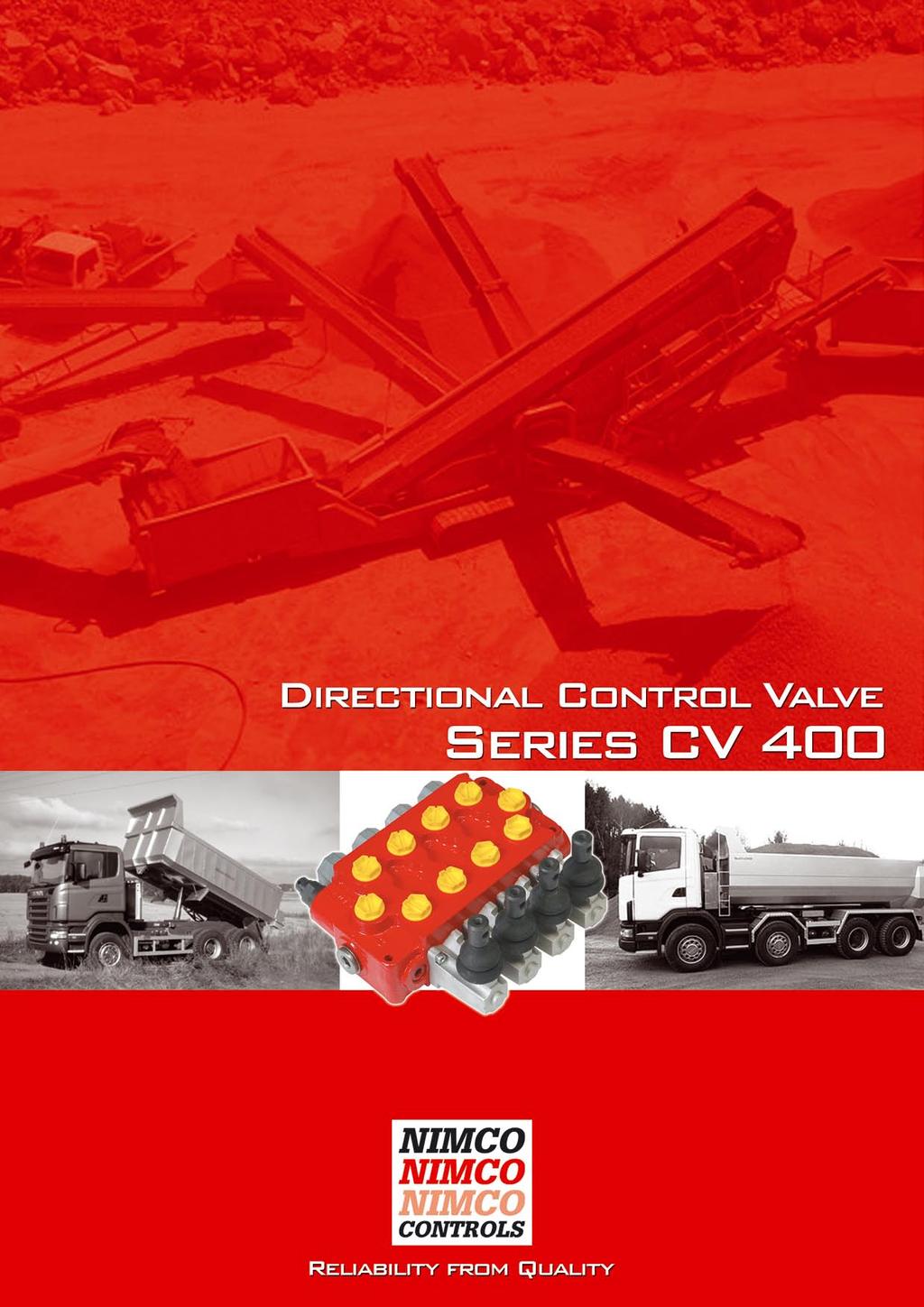
3 General Information The CV 400 Unibody is a modular monoblock valve which is available in 1 to 4 sections, with the option of additional spool functions by using a carry-over fitting (Power Beyond).The valve is designed for a maximum working pressure of 320 bar (4600 psi.) with a flow from 15 to 80 l/min (4-21 USGpm.). The CV 400 Unibody valve offers its user optimised characteristics with regard to function, capacity and quality. It is designed with the machine builders high demands of cost effectiveness, function and need of exceptionally good load maneuverbility in mind. Suitable areas of use are forklift trucks, cranes, loaders and other equipment where precise load control is required. Although the valves external dimensions are small, it will allow high internal flows and can be equipped with a large number of accessories as standard. The uniquely designed canal system results in exceptionally low pressure drops leading to improved performance and longer life not only of the control valve but also of the other components in the hydraulic system. The CV 400 Unibody is manufactured using the highest quality alloy cast iron which in combination with NIMCO s advanced machining and control methods assures the precise accuracy of every component. Each valve is tested and the results documented prior to despatch. Unibody The Unibody system is designed to give the valve user maximum flexibility and economy. The system comprises of a standard valve onto which a number of secondary valves can be mounted. Any combination of valves, already available in the program, and future developments in reponse to customer requests, can be mounted onto the valve in any preferred combination. Having all secondary valves directly on the valve, piping and hosing costs are kept to a minimum. Simultaneously, the user is allowed flexibility in designing the hydraulic system for each machine. The valve can be delivered with the Unibody functions already fitted to the valve or simply prepared for any of the large number of standard Unibody blocks that are available. Minimised spool leakage. Hard chromium plated spools, low friction and a specially developed honing method gives absolute minimum spool leakage of the valve. Easy assembly. The valve has two pressure inlets and three tank outlets allowing pipes and hoses to be connected either from the side or top of the valve. Directional Control Valve 3
4 General Information Excellent load control. CV 400 Unibody is delivered with a wide range of standard spools each of which is designed to provide optimum control characteristics within its flow range. On request, special spools can be delivered for other flow rates. Full utilisation of the spool stroke. The optimised soft maneuver grooves integrated in each spool and the precise machining of every component the entire stroke of the spool can be used. This allows full control of the load whether the operator is using very little or full flow capacity. In addition the movement of any spool in any direction will give the same speed of machine function, enhancing security and reliability. Multifunctional control. Several spools can be operated at the same time even when very large differences in load are at hand due to the utilisation of the differential pressure built up inside the valve during operation. Uniform and low lever forces. By combining the unique design features of the valve body and the spools, an excellent balance of the dynamic forces is achieved throughout the entire pressure and flow range. This keeps spring forces at a minimum and makes the valve very easy to operate by hand lever as well as when any of the NIMCO s remote control valves are used. Wide range of accessories. The CV 400 Unibody offers a wide range of options by using existing and future accessory valves. Also a wide range of spool and remote controls such as single or joystick wire controls, pneumatic and hydraulic proportional or on/off controls are available. Directional Control Valve 4
5 Technical Data Max. pressure setting Main relief valve Port relief valve Tank line Flow rates Maximum for the valve Temperature range Standard seals Spool leakage at 100 bar (1450 psi) and 25 mm2/s (cst) (117 SSU) viscosity A and B port Filtration Contamination level equal to or better then Viscosity Recommended operating viscosity range Start viscosity up to Weight CV 401 CV 402 CV 403 CV 404 Weight/Unibody option Single Double Operating force necassary to move the spool Spring centred Detent in Detent out bar l/min. 80 C -40 to +80 cm3/min 4 18/14 according to ISO 4406 mm2/s(cst) kg N Psi USGpm 21 F -40 to +176 inch3/min 0.24 NAS 1638-class 10 SSU lbs kp Directional Control Valve 5

")
 T")
6 Performance Curves Pressure Drop P T Pressure Drop P A(B) Pressure Drop A(B) T Directional Control Valve 6
7 Dimensions - Basic Valve Dimensions L1 mm (inch) L2 mm (inch) CV (3.98) 77 (3.03) CV (5.67) 120 (4.72) CV (7.36) 163 (6.42) CV (9.06) 206 (8.11) Port Size BSP Metric SAE A,B 1/2 M 18 x 1.5 3/4-16 SAE8 P1, P2, T2, (T3) 1/2 M 18 x 1.5 3/4-16 SAE8 T1 3/4 M 22 x /16-12 SAE12 Directional Control Valve 7
8 Dimensions - Unibody Dimensions L1 mm (inch) L2 mm (inch) CV (3.98) 77 (3.03) CV (5.67) 120 (4.72) CV (7.36) 163 (6.42) CV (9.06) 206 (8.11) Port Size BSP Metric SAE A,B 1/2 M 18 x 1.5 3/4-16 SAE8 P1, P2, T2, (T3) 1/2 M 18 x 1.5 3/4-16 SAE8 T1 3/4 M 22 x /16-12 SAE12 Directional Control Valve 8

9 Secondary Valve Main relief valve. Differential operated relief valve for the main circuit. Adjustable from 35 to 320 bar ( psi). Part No: 4S-4076 Order code: RV+pressure setting Check valve. Can be used when two or more valves are connected in series and operates with the same pressure. The first valve should then be equipped with a main relief valve RV and the subsequent valves with CV. Part No: 4S-4094 Graphs valid for 25 mm2/s (cst.) (117 SSU). 70 bar = 1000 psi Cylinder port mounted secondary valves. Relief valve. Differential operated port relief valve preventing pressure peaks. Fixed pressure setting from 35 to 330 bar ( psi). Order code: CV Part No: 4S-4030 Anti-cavitation valve. Check valve used to level under pressures that can occur in the cylinder ports. Order code: C+pressure setting Part No: 4S-4226 Order code: A Relief anti-cavitation valve. Works as both port relief and anti-cavitation valve. Part No: 4S-4070 Characteristics according to C and A. Order code: CA+pressure setting Directional Control Valve 9


10 Spools All of NIMCO s spools are designed for specific flow rates in order to achieve optimal control characteristics and to fully utilise the spools entire stroke. By optimising the balance between spools and valve housing, spring forces are minimized and exact maneuvering is achieved. In addition to our standard spools are there a wide range of specially designed spools to maximize load control at different pump flows and applications. Please contact our factory or any authorized distributor for further information. Spool type Symbol Order code Standard spool Part No. Double acting 1S 3B-4002 Single acting 2SA 3B-4004 Single acting B 2SB 3B-4122 Double acting with float position 3S 3B-4061 Motor 4S 3B-4035 Double acting with built in check valves 5S 4S Regenerative 6S 3B Control characteristics P-A/B 1.Press. 50 bar (725 psi) 2.Press. 150 bar (2175 psi) 3.Press. 250 bar (3625 psi) A/B-T Viscosity 25 mm2/s (cst) 50 Standard spool Pump flow 50 l/min (13.2 USGpm). Directional Control Valve 10
11 Spool Controls Code Type A-side B-side Type Code 9 9M Spring centered. Marine version. Hand lever vertical. Other length on request. S M Detent in position 1, 2 and 3 Marine version Hand lever horizontal. S2 10S Detent in pos. 1, 2, 3 and straight through spool. Standard Control Hand lever vertical. Encased. S5 11 Spring centered. Detent in pos Spring centered. Detent in pos. 3 and Spring centered. Detent in pos. 2. Hand lever vertical. Encased. Marine version. S5M 14 Spring centered. Detent in pos Spring centered. Detent in pos. 2 and 4. Spring centered. Detent in pos. 1, 2, 3 and 4. Joystick for dual-spool control. S6 Directional Control Valve 11
12 Spool Controls Code Type A-side B-side Type Code EDA EHP Electrical direct acting solenoid on - off. 12 V / 3.6 A 24 V / 1.8 A Electrical hydraulic proportional. 12V/1.5 A 24V/0.75 A Electrical hydraulic proportional. 12V/1.5 A 24V/0.75 A with manual hand lever override Wire control for 3-position spool. EHP 3W EP Electropneumatic on-off. 12V/270mA alt. 24V/150mA. Wire control for 4-position spool. 4W EK External kickout. From pos. 3 to pos. 1. H Hydraulic on/off. Pilot pressure 6-15 bar ( psi) HP Hydraulic proportional. Pilot pressure 6-15 bar ( psi) P Pneumatic on/off. PP Pneumatic proportional. Directional Control Valve 12
13 Accessories High pressure carry-over adaptor (Power Beyond), should be installed in the T1-port when two or more valves are used in the same circuit. T2 must then be connected to tank. Tank port reduction adaptor, can be installed in the T1 port when the thread size is to be reduced from BSP 3/4 to BSP 1/2 or from SAE12 to SAE 8. Directional Control Valve 13

14 Order Code Directional Control Valve 14
15 Appendix Directional Control Valve 15
16
Contents. Directional Control Valve 2 Series CV 300
 Contents Page 3 General Information Page 4 Technical data Page 5 Dimensions Page 6 Secondary Valves Page 7 Cylinder port mounted secondary valves Page8 Spool - Control characteristics Page 9-10 Spool Controls
Contents. Directional Control Valve 3 Series CV 452. Page 3-4. General Information. Page 5. Technical data. Page 6. Performance Curves.
 Contents Page 3-4 Page 5 Page 6 Page 7 Page 8 Page 9 Page 10 Page 11 Page 12 Page 13 Page 14 General Information Technical data Performance Curves Dimensions - Basics Valve Dimensions - LS Valve Secondary
Directional Control Valve CV550
 www.nimco-controls.com Directional Control Valve CV550 Smart Solutions... for the Future Contents Page 5 Page 6 Page 7 Page 8 Page 9 Page 10 Page 11 Page 12 Page 13 Page 14 Page 16 Page 17 Page 18 Page
Page 3 Page 4 Page 6 Page 8 Page 9 Page 10 Page 11
 Contents Page 3 Page 4 Page 6 Page 8 Page 9 Page 10 Page 11 General Information Compact Loader Valves Medium Size Loader Valves Large Size Loader Valves 3rd, 4th and 5th Function Valves Cable Joystick
Contents. Directional Control Valve 2 Series EPCV 452. Page 3. General Information. Page 4-5. Technical data. Page 6. Performance Curves.
 Contents Page 3 Page 4-5 Page 6 Page 7 Page 8 Page 9 General Information Technical data Performance Curves Dimensions : Hydraulic Valve and Accumulator Hydraulic Schematics Order Code Directional Control
Directional Control Valve Equipment for Front End Loaders
 Directional Control Valve Equipment for Front End Loaders CONTENT nimco Page 3 General Information Page 4 Page 5 Page 7 Page 11 Page 12 Technical Data Application Example System Options Quickview Flow
Monobloc and Sectional Directional Control Valves
 Monobloc and Sectional Directional Control Valves motion and progress 1/220 6 Monobloc directional control valves Contents 6.1 General specifications 66 6.2 Dimensional data 67 6.3 Performances curves
HYDRAULICS VINCKE DIRECTIONAL CONTROL VALVES
 VINCKE DIRECTIONAL CONTROL VALVES TECH-DCV200.1 index 3 link to your page / link a su página Monoblock hydraulic distributors Monoblock hydraulic distributors 35 liters 3 P35 Monoblock hydraulic directional
Directional control valve / RM 270
 Directional control valve / 31-02-RM270-05 Nordhydraulic AB P.O Box 189 (Industrivägen 15) SE-872 24 KRAMFORS Sweden Solutions that power your visions Telephone: Int. +46 612 71 72 00 Telefax: Int. +46
Commercial Shearing (Pty) Ltd THE WORLDWIDE PROGRAM OF VALVES ISO 9001
 Ltd THE WORLDWIDE PROGRAM OF VALVES ISO 9001") Commercial Shearing (Pty) Ltd THE WORLDWIDE PROGRAM OF VALVES ISO 9001 An Insight into Valve Technology CLEAN ROOM ASSEMBLY AND TEST A major investment has been made in a clean-room assembly and test environment.
Commercial Shearing (Pty) Ltd THE WORLDWIDE PROGRAM OF VALVES ISO 9001 An Insight into Valve Technology CLEAN ROOM ASSEMBLY AND TEST A major investment has been made in a clean-room assembly and test environment.
Monobloc and Sectional Directional Control Valves
 Monobloc and Sectional Directional Control Valves 200 P 991210 E 03 / 10.04 1/220 2 Monobloc directional control valves HDM140 Contents 2.1 General specifications 9 2.2 Dimensional data 10 2.3 Performances
MONOBLOCK DIRECTIONAL CONTROL VALVES
 MONOBLOCK DIRECTIONAL CONTROL VALVES CONTENTS: RM0...... RM5...... RM40P...... RM80...... RMD90...... MRP70... Page 1/19&/19 /19...5/19 6/19...10/19 11/19...15/19 16/19&17/19 18/19&19/19 MONOBLOCK DIRECTIONAL
Monoblock Directional Control Valve RM 230
 Monoblock Directional Control Valve RM 230 Key valve features RM 230 light is a monoblock valve, designed for max. operating pressures up to 3,000 psi (210 bar) and typ. pump flows up to 20 gpm (70 Lpm).
NV452 Monoblock directional control valve
 NV452 Monoblock directional control valve Product Features General Specifications Order Coding Open Center Load Sense Performance Data Inlet Options Spool Positioners Spool Options Auxilary Valves Lever
Sectional Directional Control Valve RSQ 240
 Sectional Directional Control Valve RSQ 0 Key valve features RSQ 0 is a sectional open center valve, designed for max. operating pressures up to 50 bar and max. pump flows up to 00 l/min. It is available
Post-Compensated Proportional Valve CV2000LS
 www.nimco-controls.com Post-Compensated Proportional Valve CV2000LS Smart Solutions... for the Future Contents Page 5 Page 6 Page 7 Page 8 Page 9 Page 10 Page 11 Page 12 Page 13 Page 14 Page 15 Page 16
ORV-M45. Contents. Additional Informations
 Contents Working Conditions 3 Dimensional Data 4 Hydraulic Circuit 5 Performance Data And Curve 7 Inlet Relief Options 8 Ordering Codes 9 Spool Options 11 Spool Positioners Side of Return 14 Spool Positioners
Auxiliary valves. Lever. Spool positioner Check valve Spool
 Auxiliary valves Lever Spool positioner Check valve Spool CONTENTS: Page -Technical data... 1 -Dimensions RP80... 2 -Dimensions RP60... 3 -Lever mechanism... 4 -Spools/spool control... 5 -Inlet cover/outlet
V050 SERIES DIRECTIONAL CONTROL VALVE
 V5 SERIES DIRECTIONAL CONTROL VALVE TAKE CONTROL Take control with Muncie Power Products V5 directional control valve. The V5 is constructed with high-grade iron castings and nickel-plated spools for use
Available manual, pneumatic, and hydraulic spool control kits.
 Fitted with a main pressure relief valve and a load check valve on every working section. Available with parallel circuit. Optional carry-over Variety of port valves (auxiliary valves) Available manual,
Sectional Directional Control Valve RS 220
 Sectional Directional Control Valve RS 0 RS 0 is a sectional open center valve designed for max. operating pressures up to 00 bar and max. pump flows up to 0 l/min. Technical data Pressure and flow values*
CABLE TIPPING VALVE. Tipping valve type Order code IN TANK OUT Weight HYDRAULICS VALVES 2.2 FM-45 CE G 1/2 G 1/2 G 1/2.
 CABLE TIPPING VALVE Optional Mechanical tipping valve operated by cable controls series LINEA or LINEA BLOCK to suit light duty tipper trucks. Open centre hydraulic scheme according to CE standards. -
Modular Unit 6MB HYDRANOR MODULAR UNIT 6MB GENERAL DESCRIPTION. 6MB-200-**-2C General Arrangement. Rev
 MODULAR UNIT 6MB GENERAL DESCRIPTION Figure 1 6MB-200-**-2C General Arrangement Rev. 5 5.1.1 Figure 2 General Arrangement 6MB-650-**-2C The Modular Units 6 MB is a complete unit for controlling of hydraulically
V250 SERIES DIRECTIONAL CONTROL VALVES
 V SERIES DIRECTIONAL CONTROL VALVES TAKE CONTROL OF YOUR HYDRAULICS Take control with Muncie Power Products V directional control valve. The V is constructed with high-grade iron castings and nickel-plated
Monoblock Directional Control Valve PMB22TSTSAB PMB23TSTSTSLB PMB21TDLB
 Engineering & Manufacturing Solutions Specifications: FLOW RATINGS: - MB21 & MB22 10 gpm (38 lpm) - MB23 8 gpm (30 lpm) Rated up to 4000 psi (275 bar). Port Sizes: - Inlet/Outlet #8 SAE. -Work Ports #8
Directional Control Valve Series 4D01 (DENISON)
") Characteristics The Denison series 4D01 is a solenoid operated directional control valve size NG06 in -chamber design. It is direct operated by wet pin solenoids. The 4D01 is available with a Soft Shift
Characteristics The Denison series 4D01 is a solenoid operated directional control valve size NG06 in -chamber design. It is direct operated by wet pin solenoids. The 4D01 is available with a Soft Shift
Hydraulic gear pumps and motors
 PL 01 T E DISPLACEMENTS From To Hydraulic gear pumps and motors 0.07 in 3 /rev (1.07 cm 3 /rev) 5.56 in 3 /rev (91.10 cm 3 /rev) through bore aluminum body PRESSURE Max. Continuous Max. Intermittent Max.
-Technical data... 2/14 -Circuit mode... 2/14 -Dimensions RP /14
 Auxiliary valves Document: SCV-1-June 2013 Lever Spool positioner Check valve Spool CONTENTS: Page -Technical data... 2/14 -Circuit mode... 2/14 -Dimensions... 3/14 -Dimensions... 4/14 -Lever mechanism...
Monobloc and Sectional Directional Control Valves
 Monobloc and Sectional Directional Control Valves motion and progress 1/220 10 Sectional directional control valves HDS20 Contents 10.1 General specifications 177 10.2 Dimensional data 178 10.3 erformances
Section 1-7. Nominal Flow 50 lpm 13 US gpm. Threads G3/8 (Standard) SAE8
 SAE8") Valve is equipped with an adjustable main relief valve, available in parallel circuit, wide range of spool options and positioners, interchangable spools Manual and remote cable Section 1 Weight 2,1 kg
Valve is equipped with an adjustable main relief valve, available in parallel circuit, wide range of spool options and positioners, interchangable spools Manual and remote cable Section 1 Weight 2,1 kg
Directional Control Valve Series D3W (Parker), 4D02 (Denison)
, 4D02 (Denison)") Characteristics Series D3W (Parker), 4D0 (Denison) The direct operated directional control valve size NG10 is available with both Parker (series D3W) and Denison (series 4D0) model codes. Both series are
Characteristics Series D3W (Parker), 4D0 (Denison) The direct operated directional control valve size NG10 is available with both Parker (series D3W) and Denison (series 4D0) model codes. Both series are
TPV Variable Displacement Closed Loop System Axial Piston Pump THE PRODUCTION LINE OF HANSA-TMP HT 16 / M / 851 / 0813 / E
 HYDRAULIC COMPONENTS HYDROSTATIC TRANSMISSIONS GEARBOXES - ACCESSORIES THE PRODUCTION LINE OF HANSA-TMP Variable Displacement Closed Loop System CONTENTS General Information... Order Code... Manual Control
SECTIONAL DIRECTIONAL VALVE HDS 30 SERIES. CROSS HYDRAULICS PTY LTD YELLOW CATALOGUE Page 3.106
 CROSS HYDRAULICS PY LD YELLOW CAALOGUE Page 3.106 Material specification: Standard features: Optional features available: Symbols: P A/B H.P.C.O. RV P 1 1 Weight CROSS HYDRAULICS PY LD YELLOW CAALOGUE
SECTIONAL DIRECTIONAL VALVE HDS 20 SERIES. CROSS HYDRAULICS PTY LTD YELLOW CATALOGUE Page 3.84
 CROSS HYDRAULICS PTY LTD YELLOW CATALOGUE Page 3.84 Material specification: Standard features: Optional features available: Symbols: P T A/B H.P.C.O. RV P 1 T 1 Weight CROSS HYDRAULICS PTY LTD YELLOW CATALOGUE
Hydraulics CONTROL VALVES
 Hydraulics CONTROL VALVES PRODUCT INDEX Series Page Series Page Series Page 90 Rotating Couplings 12 In Line Double-acting flow control 17 and shut-off control needle valves Directional Control Valves
Monoblock directional control valves DL - Directional control valve
 Monoblock directional control valves DL - Directional control valve DL Before use, carefully read the GENERAL INSRUCIONS FOR USE OF DIRECIONAL CONROL VALVES 398SMD008I00-06-2-208 DL echnical data Nominal
Vickers Pressure Relief Solenoid Operated, Two-Stage Directional Control Valve DG5S4-02 Flows to 115 l/min (30 USgpm) Pressure to 210 bar (3000 psi)
 Pressure to 210 bar (3000 psi)") Vickers Pressure Relief Solenoid Operated, Two-Stage Directional Control Valve DG5S4-02 Flows to 115 l/min (30 USgpm) Pressure to 210 bar (3000 psi) Revised 2/93 GB C 2037 Table of Contents Model Code...................................................................................................
Vickers Pressure Relief Solenoid Operated, Two-Stage Directional Control Valve DG5S4-02 Flows to 115 l/min (30 USgpm) Pressure to 210 bar (3000 psi) Revised 2/93 GB C 2037 Table of Contents Model Code...................................................................................................
SECTION A FRONT END LOADER VALVES
 NB: models, Codes and Specifications may be subject to change without notice. SECTION A FRONT END LOADER VALVES Valve Series Nominal PAGE WALVOIL FRONT-END LOADER VALVES SDM102 Series... 45L/Min... A 14
directional lever control valves
 directional lever control valves directional lever control valves Directional Lever Control Valves Directional Control Valves - Monoblock Directional Control Valves - Sectional Directional Control Valves
Directional Control Valves - Series F F130CF Constant-flow valve F150CP Constant-pressure valve. Catalog August, 1997 GB
 Directional Control Valves - F130CF Constant-flow valve F150CP Constant-pressure valve Catalog 9129 8534-02 August, 1997 GB Catalogue layout This catalogue has been designed to give a brief overview of
Flow sharing control block in mono block / sandwich plate design M6-22
 Flow sharing control block in mono block / sandwich plate design M6-22 RE 64322 Edition: 01.2015 Replaces: 05.2012 Size 22 Series 3X Maximum operating pressure on pump side 350 bar on consumer side 420
MP18 Stacking Valve System Technical Information Manual
 Electric Drives and Controls Hydraulics Linear Motion and Assembly Technologies Pneumatics Service MP18 Stacking Valve System Technical Information Manual The Drive & Control Company Copyright 1996 Bosch
Monobloc and Sectional Directional Control Valves
 Monobloc and Sectional Directional Control Valves 200--991210-N-03/09.2015 03 / 10.04 1/220 11 Sectional directional control valves HDS30 Contents 11.1 General specifications 197 11.2 Dimensional data
Pilot Operated Directional Control Valves Series D1VP, D3DP, D4P, D9P, D11P
 Characteristics Series D1VP, D3DP, D4P, D9P, D11P The D1VP is a hydraulically controlled 4/3 or 4/ way directional control valve. The valve can be operated either by the pilot ports X and Y via the subplate
TPV Variable Displacement Closed Loop System Axial Piston Pump HY-TRANS THE PRODUCTION LINE OF HANSA-TMP HT 16 / M / 501 / 1009 / E
 HYDRAULIC COMPONENTS HYDROSTATIC TRANSMISSIONS GEARBOXES - ACCESSORIES HY-TRANS THE PRODUCTION LINE OF HANSA-TMP Via M. L. King, 6-41122 MODENA (ITALY) Tel: +39 059 415 711 Fax: +39 059 415 729 / 059 415
PRPM2-A. = 5.5 Nm (4.1 lb.-ft.) (qual. 8.8 Nm (6.5 lb.-ft.) for socket cap screws. = 50 Nm (36.9 lb.-ft.) for cartridges
 (qual. 8.8 Nm (6.5 lb.-ft.) for socket cap screws. = 50 Nm (36.9 lb.-ft.) for cartridges") Technical Information General Description proportional pressure reducing valves keep a constant pressure p red on the secondary, or regulated, side, independent of pressure fluctuations on the primary
Technical Information General Description proportional pressure reducing valves keep a constant pressure p red on the secondary, or regulated, side, independent of pressure fluctuations on the primary
APV - load sensing VAlVe
 APV - load sensing VAlVe APV16: APV 22: Max. flow : port A/B 120 l/min 330 l/min port A/B without compensator 140 l/min 380 l/min Max. pressure: port P/A/B 420 bar 420 bar Nominal pressure drop over 2-way
MP18/SIC & SIO Stacking Valve System Technical Information Manual
 Electric Drives and Controls Hydraulics Linear Motion and Assembly Technologies Pneumatics Service MP18/SIC & SIO Stacking Valve System Technical Information Manual The Drive & Control Company Copyright
MDT. Monoblock directional control valves MDT - Directional control valve
 Monoblock directional control valves - Directional control valve efore use, carefully read the GENERL INSRUCIONS FOR USE OF DIRECIONL CONROL VLVES echnical data Nominal flow 35 l/min 9. US gpm Nominal
Selector Valve RV 713
 Selector Valve RV 713 Key valve features RV 713 is a 3 way selector valve designed for flows up to 42gpm (160 Lpm) and max. operating pressures up to 3,625 psi (250 bar). Spools, both 2 and 3 position,
VINCKE HYDRAULIC PUMPS
 : VNK BA10VS 21 Variable displacement axial piston pump of swashplate design for hydraulic open circuit systems. Flow is proportional to drive speed and displacement. It can be infinitely varied by adjustment
HYDRAULICS VINCKE HYDRAULIC PUMPS
 VINCKE HYDRAULIC PUMPS TECH-VHP200.1 index 3 link to your page / link a su página Gear pumps Introduction 3 Group 0 3 Group 1 3 Group 2 3 Group 3 4 6 7 12 18 Variable displacement pumps 21 Hand pumps 3
HYDRAULIC CONTROL VALVES
 HYDRAULIC VALVES SECTION 3A HYDRAULIC CONTROL VALVES MONOBLOCK DIRECTIONAL CONTROL VALVES...71 SLICE DIRECTIONAL CONTROL VALVES...73 HANDLEVERS...76 S additions for valves...76 VALVE CONTROL KITS additions
Flow sharing control block in mono block / sandwich plate design M6-15
 Flow sharing control block in mono block / sandwich plate design M6-15 RE 64321 Edition: 01.2015 Replaces: 05.2012 Size 15 Series 3X Maximum operating pressure on pump side 350 bar on consumer side 420
NB: models, Codes and Specifications may be subject to change without notice. SECTION A DIRECTIONAL CONTROL VALVES MANUAL DIRECTIONAL VALVES
 NB: models, Codes and Specifications may be subject to change without notice. SECTION A DIRECTIONAL CONTROL VALVES MANUAL DIRECTIONAL VALVES Valve Series Page...... A 2 WALVOIL FRONT-END LOADER VALVES...
Pilot Operated Directional Control Valves Series D31DW, D41VW - D111VW
 Characteristics The D31, D41, D81, D91 and D111 are electrically controlled 4/3 or 4/ way directional control valves. The valves are pilot operated by an NG6 valve. Pressure and flow of the pilot oil have
CMA200 Advanced Subject Independent-Metering title Mobile Valve. 200LPM 440 bar CAN Bus
 CMA200 Advanced Subject Independent-Metering title Mobile Valve 200LPM 440 bar CAN Bus Contents Introduction 3 Specifications and performance 4 CMA200 advanced sectional mobile valves Cross sections 7
2.4 HEAVY DUTY SERIES
 2 2.4 HEAVY DUTY SERIES CONTENTS PPV102 Ordering Code 2.4.1 Heavy Duty Series 2.4.2 Heavy Duty Series compensator 2.4.3 Standard gear pump models Technical Information 2.4.4 Specifications 2.4.5 Hydraulic
DIRECTIONAL CONTROL VALVES CETOP3
 DIRECTIONAL CONTROL VALVES CETOP3 GENERAL DESCRIPTION RH0...1-...F... Document: DCVC3-1-Aug 2013 4/3- and 4/2- way directional control valves with solenoid operation, heavy duty construction RH0...1-...F...
Pilot control unit with end position lock for the remote control of directional valves
 Pilot control unit with end position lock for the remote control of directional valves RE 64 553/02.07 1/12 Replaces : 05.05 Type 4THF6 or 5THF6 Series 2X Contents Functional description, section, symbol
Variable Displacement Pump A4VG for closed circuits
 RE 92 003/05.99 RE 92 003/05.99 replaces: 02.98 Variable Displacement Pump A4VG for closed circuits Sizes 28...250 Series 3 Nominal pressure 400 bar Peak pressure 450 bar A4VG...EP Index Features 1 Ordering
10 SERIES MODULAR VALVES
 General Information Mounting Surface : ISO 441-A-1-4-A, CETOP-1, NPA-D1 Up to 5 MPa (363 PSI), 8 L /min (11 U.S.GPM) Pub. EC-145 The modular valves are functional elements with which a hydraulic system
LOAD SENSE SECTIONS. Series 20. Directional Control Valves NEED NEW PIC VALVES STANDARD FEATURES SPECIFICATIONS
 Directional Control Valves LOAD SENSE SECTIONS NEED NEW PIC Series 20 STANDARD FEATURES Control and reduced Dead Band (20I) and Tie Rod Kits SPECIFICATIONS Pressure Rating Foot Mounting Maximum Operating
General Valve Assembly Information
 General Assembly Information Open-Center Directional Control Valves General Valve Assembly Information The Basics Every valve has the following elements: Inlet Main relief Work sections Outlet Section
Truck Hydraulics. Serie VP1 Variable Displacement Pumps
 ruck Hydraulics Variable Displacement Pumps aerospace climate control electromechanical filtration fluid & gas handling hydraulics pneumatics process control sealing & shielding Contents Pump and line
Dual Axis Hydraulic Joystick Series JH4
 Dual Axis Hydraulic Joystick Series JH4 03.JH4-0911 Index of content: Description & technical data: Page 3 Hydraulic circuit diagrams (joysticks): Page 4 Typical hydraulic circuit diagrams (system): Page
SECTION A OIL PILOT CONTROLS
 NB: models, Codes and Specifications may be subject to change without notice. SECTION A OIL PILOT CONTROLS SVM400 ** NEW ** SV10 SV20 SV30 SVP500 SV40 SV50/51 SV60 SV70 Valve Series PAGE HYDRAULIC PILOT
DIRECTIONAL CONTROL VALVES CETOP3
 DIRECTIONAL CONTROL VALVES CETOP3 CONTENTS: RH06...1 - electrical control... RH06...2 - hydraulic control... Page 1/17...7/17 8/17...9/17 RH06...4 - mechanical control RH06...6 - pneumatic control......
Pressure Control Valves. General Description. Specifications. Ordering Information
 Catalog HY14-3000/US Technical Information Control Valves Series RCP General escription Series RCP in-line pressure control valves are chiefly used as remote control valves. They limit system pressure
TPV Variable Displacement Closed Loop System Axial Piston Pump THE PRODUCTION LINE OF HANSA-TMP HT 16 / M / 852 / 0815 / E
 HYDRAULIC COMPONENTS HYDROSTATIC TRANSMISSIONS GEARBOXES - ACCESSORIES Certified Company ISO 9001-14001 ISO 9001 Via M. L. King, 6-41122 MODENA (ITALY) Tel: +39 059 415 711 Fax: +39 059 415 729 / 059 415
HV SERIES. Manual/ Proportional Directional Valves HV9 HV39 HV18. EPHV39 Lever Actuated with Optional Proportional Control
 INDUSTRIL FLUID OWER COMONENTS ND SYSTEMS HV SERIES Manual/ roportional Directional Valves HV39 HV9 HV8 EHV39 Lever ctuated with Optional roportional Control 334 Friendship Drive, Magnolia, TX 77355 Tel.:
Page 3 Page 4 Page 5 Page 6 Page 7 Page 8-9 Page 10 Page 11
 Contents Page 3 Page 4 Page 5 Page 6 Page 7 Page 8-9 Page 10 Page 11 General Information Assembly Dimensions Joystick Movements Technical data Order Code Configurations Optional Handgrip Inserts Assembly
Contents. Quality Hydraulic Components from the Webtec Range. Introduction. Hydraulic Flow Control Valves
 Quality Hydraulic Components from the Webtec Range Contents Description Section Webtec Products Ltd Introduction 1 Hydraulic Flow Control Valves 2 Hydraulic Directional Control Valves and Check Valves
Publ. 3-EN 2950-A. DENISON HYDRAULICS Pressure Relief Valve R6V
 Publ. 3-EN 2950-A DENISON HYDRAULICS Pressure Relief Valve R6V FEATURES, SYMBOL FEATURES High Performance: R6V valves are designed for a maximum pressure of 350 bar and a flow capacity up to 650 l/min.
Directional Control Valve
 Directional Control Valve Service and Parts Manual powersolutions.danfoss.com Directional Control Valves Service and Parts Manual: Contents SERVICE PARTS Inlet cover... 3-4 Outlet cover... 5-6 Standard
Pilot-Operated Directional Control Valves Series D3 - D11
 Catalogue HY11-500/UK Characteristics The D31, D41, D81, D91 and D111 are electrical controlled 4/3 or 4/ way directional control valves. The valves are pilot-operated by an NG6 valve. Pressure and flow
485 - NC NO/DA DN
 485 - NC 285 - NO/DA DN 25-100 The 485/285 diaphragm valve is particularly suitable for shutting off and regulating abrasive or dirty fluids. The new internal geometry of the body optimises fluid dynamic
EMTEC Series 3-Screw
 EMTEC Series 3-Screw Coolant and Emulsion Pumps The reliable pump people Rotary Screw Pumps Performance Shown at 1.8 cst, 3500 RPM Differential Pressure PSI 20-38 20-46 20-56 40-38 40-46 80-36 80-46 140-39
Hydro M t HYDRAULIC VALVES SN-4.
 Hydro HYDRAULI VALVES A SRONG OMMIMEN O QUALIY Our concept is to sell and deliver the best quality of hydraulic valves, that fully meet our customer s rigorous requirements! o this end, our quality control
HYDRAULIC COMPONENTS HYDROSTATIC TRANSMISSIONS
 HYDRAULIC COMPONENTS HYDROSTATIC TRANSMISSIONS T E C H N I C A L C A T A L O G Hydraulic components POCLAIN HYDRAULICS Methodology : This document is intended for manufacturers of machines that incorporate
Pilot Operated Pressure Relief Valve Series R5V (Denison)
") Characteristics Pilot operated pressure relief valves series R5V have a similar design to the subplate mounted R4V series. The SAE flanges allow to mount the valves directly on the outlet flanges of pumps
Characteristics Pilot operated pressure relief valves series R5V have a similar design to the subplate mounted R4V series. The SAE flanges allow to mount the valves directly on the outlet flanges of pumps
IGP /117 ED INTERNAL GEAR PUMPS SERIES 10 OPERATING PRINCIPLE TECHNICAL SPECIFICATIONS HYDRAULIC SYMBOL
 00/7 ED IGP INTERNAL GEAR PUMPS OPERATING PRINCIPLE IGP pumps are volumetric displacement pumps with internal gears, available in five sizes, each divided into a range of different displacement. The pumps
Mobile Directional Valve. Product Catalog MDG for Mobile Equipment Flows to 60 I/min (15.8 USgpm)
") Mobile Directional Valve Product Catalog MDG for Mobile Equipment Flows to 60 I/min (15.8 USgpm) Table of Contents General Information...3 Model code Valve Section...4 Valve Assembly...5 Spool Data...6
Mobile Directional Valve Product Catalog MDG for Mobile Equipment Flows to 60 I/min (15.8 USgpm) Table of Contents General Information...3 Model code Valve Section...4 Valve Assembly...5 Spool Data...6
Directional Controls
 Vickers Directional Controls Wet Armature Solenoid Operated Directional Control Valves Model DGV-, Series Typical Construction of a Spring-Centered DC Valve with Variable Speed Pilot Control passage Speed
DSH* /117 ED LEVER OPERATED DIRECTIONAL CONTROL VALVE MOUNTING SURFACES DSH3 ISO DSH5 ISO
 41 600/117 ED DSH* LEVER OPERATED DIRECTIONAL CONTROL VALVE MOUNTING SURFACES DSH3 ISO 4401-03 DSH5 ISO 4401-05 p max (see performances table) Q nom (see performances table) OPERATING PRINCIPLE The DSH
Proportional Directional Valve System
 roportional Directional Valve System in Sectional Design Reference: 31--9589-ENG-2 Issue: 8.215 1/2 Contents age 1 General... 3 1.1 Description... 3 1.2 pplication examples... 3 2 Technical data... 3 3
CLS180 Proportional Load Sensing Mobile Valve
 Mobile valves Proportional Load Sensing, Model CLS180 350 bar 180 L/min Up to 10 sections Eaton Pro-FX TM Ready CLS180 Proportional Load Sensing Mobile Valve Overhaul manual / Trouble shooting guide Contents
HYDRAULIC PILOT CONTROL UNIT OF SANDWICH PLATE DESIGN
 01 /10 2.2 HYDRULIC PILOT CONTROL UNIT OF SNDWICH PLTE DESIGN Type: H*-2TH6 Benefits: Progressive, sensitive control Precise and play-free control characteristics Low actuation force at the lever Rust-free
4-Way Directional Control With Pressure Compensated Flow Control PSDCF120M64LF Specifications:
 Engineering & Manufacturing Solutions With Pressure Compensated Flow Control Specifications: Rated for 0-18 gpm (0-68.1 lpm) Rated for 3000 psi (207 bar) Weighs 6-1/2 lbs. (2.9 kg) 30 Micron filtration
Gear Pumps / Motors. Series PGP / PGM Fixed Displacement Pumps, Cast-Iron and Aluminium Designs
 Gear Pumps / Motors Series PGP / PGM Fixed Displacement Pumps, Cast-Iron and Aluminium Designs Table of contents Heavy-duty Pumps and Motors Series PGP, PGM Contents Page Series 500 Aluminium Table of
2.3 MEDIUM HEAVY DUTY SERIES
 2 2.3 MEDIUM HEAVY DUTY SERIES CONTENTS PPV11 Ordering Code 2.3.1 Medium Heavy Duty Series 2.3.2 Torque limiter settings Technical Information 2.3.3 Specifications 2.3.4 Hydraulic fluids 2.3.5 Viscosity
Vane Pumps. VMQ Series Vane Pumps For Industrial and Mobile Applications Displacements to 215 cm 3/ r (13.12 in 3 /r) Pressures to 260 bar (3800 psi)
 Pressures to 260 bar (3800 psi)") Vickers Vane Pumps VMQ Series Vane Pumps For Industrial and Mobile Applications Displacements to 215 cm 3/ r (13.12 in 3 /r) Pressures to 260 bar (3800 psi) 5008.00/EN/0596/A A.25 Introduction From the
Vickers Vane Pumps VMQ Series Vane Pumps For Industrial and Mobile Applications Displacements to 215 cm 3/ r (13.12 in 3 /r) Pressures to 260 bar (3800 psi) 5008.00/EN/0596/A A.25 Introduction From the
INSTALLATION DIMENSIONS
 ACCESSORIES & OTHERS PRESURE GAGE INSTALLATION DIMENSIONS UNIT mm(inch) LM TYPE CBM TYPE CBM-F TYPE MODEL B B1 D D1 D2 G H T d R G40LM 28.1(0.86) φ48(1.9) φ41.7(1.6) 8(0.31) 58.7(2.31) 1/8" G40CBM 26(1.02)
RV1P /118 ED VARIABLE DISPLACEMENT VANE PUMPS SERIES 10 OPERATING PRINCIPLE TECHNICAL SPECIFICATIONS HYDRAULIC SYMBOL
 14 201/118 ED RV1P VARIABLE DISPLACEMENT VANE PUMPS OPERATING PRINCIPLE TECHNICAL SPECIFICATIONS (measured with mineral oil with viscosity of 46 cst at 40 C) RV1P are variable displacement vane pumps with
PUMP SIZE Flow rate at 1500 rpm lt/min Operating pressures bar
 /7 ED VPPL VARIABLE DISPLACEMENT AXIAL-PISTON PUMPS FOR INTERMEDIATE PRESSURE SERIES OPERATING PRINCIPLE The VPPL are variable displacement axial-piston pumps with variable swash plate, suitable for applications
COMPACT CATALOG MONOBLOCK DIRECTIONAL CONTROL VALVES
 COMAC CAALOG MONOBLOCK DIRECIONAL CONROL VALVES SD4 Features Simple, compact designed, this valves is only one section for open center and closed center hydraulic systems. H Fittedwithamainpressurereliefvalve.
Directional Control Valve. Formerly the RSM290 Series. Technical data. Pressures / Flows Max. operating pressure set per port:
 X-Series Directional Control Valve DX- Formerly the RSM90 Series DX- is a sectional valve designed for max. operating pressures up to 000 psi (0 bar) and max. pump flows up to 80 l/min with Q-inlet. For
VALVES POWER TRANSMISSION T E C H N I C A L C A T A L O G
 VLVES POWER TRNSMISSION T E C H N I C L C T L O G Power transmission POCLIN HYDRULICS Methodology : This document is intended for manufacturers of machines that incorporate Poclain Hydraulics products.
PISTON MOTORS FOR CLOSED LOOP SYSTEMS types HMF/A/V/R-02
 1-control optional swashing to 0 cc /rev 2-swash plate hydrostatic bearing 3-piston-slipper assembly 21 swash angle 4-housing monoshell for high rigidity 5-valve plate housing highly integrated 6-control
LUDV control block in mono block/sandwich plate design M7-20
 LUDV control block in mono block/sandwich plate design M7-20 RE 64293 Edition: 06.2013 Replaces:. Size 20 Series 3X Maximum operating pressure On the pump side 380 bar On the actuator side 420 bar Maximum