SUBJECT: PUMP TYPES & OPERATIONS
|
|
|
- Bathsheba Bruce
- 5 years ago
- Views:
Transcription
1 SUBJECT: PUMP TYPES & OPERATIONS ABOUT THE SESSION This session will highlight different types of pumps and its working. INTRODUCTION In Hydraulic system, the pump converts mechanical energy (hydraulic horsepower) by pushing fluid into the system. All pumps work on the same principle generating an increasing volume on the intake side and a decreasing volume on the discharge side; but the different types of pumps very greatly in methods and sophistication.
2 TABLE OF CONTENTS TYPES OF PUMPS 1. Non Positive Displacement Pump 2. Positive Displacement Pump 2.1 Internal Gear Pump 2.2 External Gear Pump 2.3 Vane Pump Fixed Displacement Single Pump Double Pump 2.4 Vane Pump Variable Displacement 2.5 Piston Pump Radial Piston Arial Piston Bent Axis Piston
3 OBJECTIVES: To understand in depth, the working of the following sophisticated pumps used in latest power hydraulic systems. Gear Pumps Vane Pumps Piston Pumps PUMP RATINGS A pump is generally rated by its maximum operating pressure capability and output flow at a given drive speed. The pressure rating of a pump is determined by the manufacturer and is based upon reasonable service-life expectancy under specified operating conditions. Flow capacity of a pump can be expressed as displacement per revolution.

4 TYPES OF PUMPS There are two basic types of pumps. Non-Positive Displacement Pump Positive Displacement Pump 1. Non-Positive Displacement Pump - Centrifugal Pump This pump design is used mainly for fluid transfer in systems where the only resistance found is created by the weight of the fluid itself and friction. Most non-positive displacement pumps. (Figure 17-2) operate by centrifugal force. Fluids entering the center of the pump housing are thrown to the outside by means of a rapidly driven impeller. There is no positive seal between the inlet and outlet ports, and pressure capabilities a function of drive speed. Although it provides a smooth, continuous flow, the output from this type of pump is reduced as resistance is increased. In fact, it is possible to completely block off the outlet while the pump is running. For this and other reasons, non-positive displacement pumps are seldom used in power hydraulic systems today. These properties make it a more likely choice for a water pump in a car engine, dishwasher or washing machine. It could also be used as a supercharge pump for a positive displacement pump.
5 2. Positive Displacement Pump The positive displacement pump is most commonly used in industrial hydraulic systems. A positive displacement pump delivers to the system, a specific amount of fluid per stroke, revolution, or cycle. This type of pump is classified as fixed or variable displacement. Fixed displacement pumps have a displacement which cannot be changed without replacing certain components. With some, however, it is possible to vary the size of the pumping chamber (and the displacement) by using external controls. These pumps are known as variable displacement pumps. Certain vane pumps and piston units can be varied from maximum to zero delivery. Some are capable of reversing their flow as the control crosses a center or neutral position. The pressure is determined by the workload, and except for leakage losses, the output is independent of outlet pressure. This makes the positive displacement pump more appropriate for use in the transmission of power. The three best-known positive displacement pumps: gear pumps, vane pumps, and piston pumps.
 is connected to the tank. The pressure side (red) is connected to the hydraulic system.")
6 2.1 GEAR PUMP WITH INTERNAL GEARING It comprises mainly a housing (1), in which a pair of gears run with such low axial and radial play, that the unit is practically oil-tight. The suction side (blue) is connected to the tank. The pressure side (red) is connected to the hydraulic system. The inner gear 2 is driven in the direction of the arrow, and takes external gear 3 along with it in the same direction. The rotary movement causes the gears to separate, so that the gear spaces are free. The negative pressure caused by this and the atmospheric pressure on the fluid level in the tank cause fluid to run from the tank to the pump. One generally says the pump sucks. The fluid fills the gear spaces, which form closed chambers with the housing and the crescent 4, during further movement, and is pushed to the pressure side (red). The gears then interlock once more and push the fluid from the gear chambers.

.")
7 2.2 GEAR PUMP WITH EXTERNAL GEARING The gears which would come into contact with one another prevent return flow from the pressure chamber to the suction chamber. In this case, 2 external gears would come into contact with one another. Gear 2 is driven in the direction of the arrow, and causes gear 3 to move with it in the opposite direction. The suction process is identical to that previously described for the internally geared pump. The fluid in gear chambers 4 is pushed round the outside and out of the gear spaces on the pressure side (red). It can easily be seen from the sectional drawing that the gears close the spaces before these are completely empty. Without unloading in the remaining chambers, very high pressure would occur, which would result in hard pulsating running of the pump. For this reason, unloading bores are arranged at this position on the side of the bearing blocks. The so called compressed fluid is thus fed into the pressure chamber.
8 A further point worthy of note is the side tolerance play between gears 5 and bearing blocks 6. fig. 4 It tolerance play too great low friction high leakage If tolerance play too low high friction high leakage If the tolerance play is designed as a fixed aperature, leakage increases along with wear. The volumetric loss also increases with increasing operating pressure. This pump design incorporates a hydrostatic bearing balance. The bearing blocks are pushed on to the gears by cams 7, which are affected by system pressure. Tolerance play therefore adjusts itself according to the system pressure. This results in a high degree of efficiency, independent of speed and pressure. Important technical details displacement volume cc/rev. operating pressure up to 250 bar.

9 2.3 VANE PUMPS WITH FIXED DISPLACEMENT VOLUME Single Pump Cam 1 has an internal running surface on double eccentric design. The rotor is in drive part. On its circumference, two vanes 3 (double vanes, which can be pushed against each other are fitted in radially arranged grooves. When the rotor is turned, the centrifugal force and the system pressure being one against each and radially moveable vanes towards the outside. They lie with their external edge to the inner running area of the cam. The cells (transporting chambers are formed by 2 pairs of vanes, the rotor one cam and control discuss arranged on the side. Supply (suction side, blue and system pressure side red) of the fluid take place by means of the control discs (not shown) To make things easier to understand external supply and drain are shown in the drawing (Fig.5). For flow delivery, the rotor is moved in one direction of the arrow. Near the suction line above and below), the vanes 4 are still too small if the rotor is turned further, the vanes increase and fill up with oil. When these cells have reached their maximum size (largest distance from the internal running space to the center point of the motor, they are separated from the suction side by means of control discs. They are then connected to the pressure side. The vanes are pushed into groves by the form of the cam curve. The vane volume decrease once more. The fluid is thus pushed to the pressure port.

10 As the cam curve is designed as double eccentric, each vane is involved in the delivery process twice per revolution. At the same time, two suction chamber and two pressure chambers lie opposite each other, whereby the drive shaft is hydraulic unloaded. The pressure is applied to the back of vanes 5. Better sealing is thus achieved in addition to the double seal lands. However, a friction may not be too great, both vanes in a motor grove have chamfers opposite each other (fig.6) The chamfers on the vanes cause a pressure balance between running and return side. The rolling surface of vanes remains as contact surface for the pressure. Higher contact pressure is not necessary on such suction side. The backs of the vanes are thus unloaded to tank.
 provide a single power source capable of serving two separate hydraulic circuits or providing greater volume through combined delivery.")

11 2.3.2 DOUBLE PUMP ASSEMBLIES Double pumps (figures 17.20) provide a single power source capable of serving two separate hydraulic circuits or providing greater volume through combined delivery. Most double pumps have a co on inlet in a center housing. The outlet for one unit, usually the larger of the two is the shaft end body. The second outlet is in the cover. Some types of double pumps have separate inlets, although they can be mounted in multiples. Both kinds need only one drive motor, however, double pumps that have separate inlets require separate piping. Cartridge construction for double pumps is essentially the same as in single unit, making numerous combinations of sizes and displacements possible

12 2.4 VANE PUMPS WITH VARIABLE DISPLACEMENT AND PRESSURE CONTROL With this type of pump, the displacement volume can be adjusted as the set maximum operating pressure. The delivery process follows the principle as described for fixed displacement pump V2. In this case, however, the cam is a circular concentric. A spring 2 pushes the cam into its eccentric outlet position towards the motor. The maximum eccentric and thus the maximum displacement volume can be set by means of the screw 5. The spring force can also be adjusted by means of adjustment. There is tangential adjustments of the cam by means of height adjustment screw 4. The pressure which builds up due to working resistance )e.g. at the user, cylinder with load) affects the internal running surface of the cam on the pressure side. this results in a horizontal force component which operates towards the spring (fig.8)

13 If the pressure force exceeds the set spring force (equivalent to certain pressure), the cam ring moves from eccentric towards zero position. The eccentric decreases. The delivery flow adjusts itself to the level required by the user. If no fluid is taken by the user and the set pressure is thus reached, the pump regulates flow to almost zero, operating pressure is maintained and only the leakage oil replaced, Because of this, loss of power and heating of the fluid is kept to a minimum. When the initial spring tension is achieved, the cam ring moves. Flow decreases are maintained. The gradient of the performance curve depends on the spring characteristics whereby the gradient with a certain spring and different pressure varies. To improve the sensitivity of response, the pump can be fitted with 4 different springs corresponding to 4 pressure ratings. Fig.7 also show the bleed valve 7 fitted as standard commissioning is made easier by automatic bleeding. The valve poppet is pushed back by spring the valve open. The valve remains open as long as air escapes during start up. If fluid flow through the valve, the poppet is pushed against the spring and the connection closed hermetically. Important technical data displacement volume upto 47cc rev. (4 sizes) operating pressure upto 100 bar.

14 2.5 PISTON PUMPS All piston pumps operate on the principle that a piston reciprocating in a bore will draw fluid in as it is retracted and expel it as it moves forward. The two basic designs are radial and axial, both available as fixed or variabledisplacement models. A radial pump has the pistons arranged radially in a cylinder block (Figure 17-21), while the pistons in the axial units are parallel to each other and to the axis of the cylinder block (Figure 17-22). Axial piston pumps may be further divided into in-line (swash plate) and bent-axis types. Operating Characteristics Piston pumps are highly efficient units, available in a wide range of capacities. They are capable of operating in the medium to high pressure range (200 bar to 500 bar), with some going much higher. Because of their closely fitted parts and finely machined surfaces, cleanliness and good quality fluids are vital to long service life Radial Piston Pumps In a radial pump, they cylinder block rotates on a stationary pintle inside a circular reaction ring or rotor. As the block rotates, centrifugal force, charging pressure, or some form of mechanical action causes the pistons to follow the inner surface of the ring, which is offset from the centerline of the cylinder block. Porting in the pintle permits the pistons to take in fluid as they move outward and discharge it as they move in.

15 Pump displacement is determined by the size and number of pistons (there may be more than one bank in a single cylinder block) and the length of their stroke. In some models, the displacement can be varied by moving the reaction ring to increase or decrease piston travel. Several types of external controls are available for this purpose Axial Piston Pumps In axial piston pumps, the pistons reciprocate parallel to the axis of rotation of the cylinder block. The simplest type of axial piston pump is the swash plate in-line design (Figure 17-23). The cylinder block in this pump is turned by the drive shaft. Pistons fitted to bores in the cylinder block are connected through piston shoes and a shoe plate, so that the shoes bear against an angled swash plate. As the block turns (Figure 17-24), the piston shoes follow the swash plate, causing the pistons to reciprocate. The ports are arranged in the valve plate so that the pistons pass the inlet as they are pulled out and pass the outlet as they are forced back in. Like radial piston pumps, the displacement of axial piston pumps is determined by the size and number of pistons, as well as the stroke length. Stroke length is determined by the angle of the swash plate Variable displacement pumps In variable displacement models of the in-line pump, the swash plate is installed in a movable yoke (Figure 17-25). Pivoting the yoke on pintles changes the swash plate angle to increase or decrease the piston stroke (Figure 17-22). The yoke can be positioned by any of several means, including manual control, servo control, pressure compensator control, and load sensing and pressure limiter control.

16 2.5.4 Bent-Axis Piston Pumps
17 In a bent-axis piston pump, the cylinder block turns with the drive shaft, but at an offset angle. The piston rods are attached to the drive shaft flange by ball joints and are forced in and out of their bores as the distance between the drive shaft flange and cylinder block changes (Figure 17-29). A universal link keys the cylinder block to the drive shaft to maintain alignment and assure that they turn together. The link does not transmit force, except to accelerate and decelerate the cylinder block and to overcome resistance of the block revolving in the oil-filled housing. The displacement of this pump varies between 0 to 30 degrees, depending on the offset angle (Figure 17-30).
18 SUMMARY Gear pumps and vane pumps are used in low and medium pressure industrial applications. Piston pumps specifically are used in medium and high pressure industrial applications. In short, pump is the heart of any hydraulic system. REVIEW QUESTIONS: 1. What is the difference between positive and non-positive displacement pumps? 2. Indicate the different types of positive displacement pumps. 3. Are gear pumps fixed or variable type? Justify. 4. Explain the working of fixed displacement vane pump. 5. Explain briefly the working of variable displacement vane pump. REFERENCE 1. Power Hydraulics, Michael J. Pinches and John G. Ashby. 2. Manuals of reputed Hydraulic product manufacturers.
19 SESSION - 2 BY R. RAMANI SUBJECT: AXIAL PISTON PUMPS ABOUT THE SESSION This session dwells on types and operations of axial piston pumps, focusing on special features. INTRODUCTION In Axial Piston pumps, piston reciprocates either parallel to axis or inclined to axis of rotation of cylinder block.
20 TABLE OF CONTENTS 1. Principle of Working 2. Inline Axial Piston Pump of Swashplate Design 2.1 Fixed Displacement 2.2 Variable Displacement 2.3 Pressure Compensator 2.4 Closed Loop type 2.5 HP Control Direct Operated (LD) 2.6 Hydraulic Control Pressure Related (HD) 3. Bent Axis Piston Pump 3.1 Fixed Displacement 3.2 Variable Displacement
21 OBJECTIVES: To understand in depth the function and operations of (i) fixed and variable displacement inline axial piston pump. (ii) fixed and variable displacement bent axis piston pump.

22 PRINCIPLE OF OPERATION In axial piston pumps, the pistons reciprocate parallel to the axis of rotation of the cylinder block. The simplest type of axial piston pump is the swash plate in-line design. In a bent-axis piston pump, the cylinder block turns with the drive shaft, but at an offset angle. The piston rods are attached to the drive shaft flange by ball joints and are forced in and out of their bores as the distance between the drive shaft flange and cylinder block changes.

23 2.1 Swashplate Design with Fixed Displacement Nine pistons 3 are arranged in a circle, parallel to the drive shaft 2, in a fixed housing 1. They run in a cylinder drum 4, which is connected rigidly to the drive shaft by means of a key. The piston ends are designed as universal joints and fitted in slipper pads. These are held on a 15 sloping surface 6 by thrust and retaining washers. The sloping surface is part of the housing on fixed displacement units, and the slope is thus fixed. When the drive shaft 2 is rotated (pump operation), the cylinder drum 4, collar bushes 7, cylinder cap n8, as well as piston 3 and slipper pad 5 also rotate. As the pistons are held on the sloping surface by means of the slipper pads, a piston stroke occurs in the cylinder drum when the drive shaft is turned. The control and thus the supply and drain of the oil is by means of two kidneys shaped grooves in the control plate 9, which is connected rigidly to the housing. The pistons which move out of the cylinder drum are connected with the tank side (blue) by means of the control grooves, and draw in fluid. The other pistons are connected to the pressure side (red) by means of the other control groove and push fluid by means of their stroke into the cylinder drum to the pressure port. One piston is always in the change over range from suction to pressure side or vice versa. Pressure fluid reaches the slipper bearing by means of a bore in the piston, and forms a pressure balance field there.

24 2.2 Swashplate Design with Variable Displacement Fig. 17. On the model with variable stroke displacement, the sloping plane is to a certain extent a disc and no longer part of the housing. The sloping plate 1 can move. It can be swiveled by means of an adjustment mechanism 2 through an angle of 15 to center position. The pistons 3 carry out a certain stroke, related to the slope position, i.e., the swash angle. The stroke is the determining factor for the displacement volume. The piston stroke increases with increasing angle. If the disc is in center position while the speed remains unchanged, then the flow direction changes smoothly. Design Characteristics of an Axial Unit in Swash plate Design (Type A1) 9 pistons/slipper pads level control surface through shaft swash range from 0 up to 15 short oil line. Special Characteristics: short swash times low weight good flow characteristics in zero position range

25 compact second shaft extension possible, and thus additional pumps can be fitted. well suited for reversing operation of large moment of inertia. 2.3 Compensator Operation: Operation of the in-line pump compensator control is shown schematically in Figure The control consists of a compensator valve balanced between load pressure and the force of a spring, a piston controlled by the valve to move the yoke, and a yoke return spring.
.")
26 When the outlet pressure is less than the compensator spring setting, the yoke return spring moves the yoke to the full delivery position (Figure 17-26), View A). Increasing pressure acts against the end of the valve spool. When the pressure is high enough to overcome the valve spring. the spool is displaced and oil enters the yoke piston (Figure View B). The piston is forced by the oil under pressure to decrease the pump displacement. If the pressure falls off, the spool moves back, oil is discharged from the piston to the inside of the pump case, and the spring returns the yoke to a greater angle. In this way, the compensator adjusts the pump output to whatever level is required to develop and maintain the present pressure. Avoiding relief valve operation at full pump volume during holding or clamping prevents excess power loss. 2.4 Axial Piston Pump type A4V Closed loop type Fig 18

27 Connection A, B working lines G pressure port for auxiliary circuits L1 leakage oil or oil filing L 2 leakage oil or oil drain M A measuring point working line A M B measuring point working line B R bleed port S suction port for boost oil X 1 x2 ports for control pressures Y 1 Y2 remote control ports (e.g. hand pilot valve) The axial piston variable displacement pump in swashplate design 1 is a primary unit ready for fitting; it incorporates auxiliary pump 2 for boost and pilot oil supply adjustment unit 3, combined feed and pressure relief valves, and boost pressure relief valve. One difference from the models already described is the tapered piston arrangement 7. With increasing speed, it increases the forces to retain the contact between the swashplate and the pistons. Also there is a spherical control surface 8 (advantage; self centering). This variable displacement pump is designed for closed circuit and works in boosted operation, i.e. the fluid returning from the user is fed back to the pump under boost pressure. Leakage losses are replaced by the auxiliary pump. Auxiliary pump 2 serves as a boost and control pump. A boost pressure relief valve 4 is available to limit the maximum boost pressure. Two built-in pressure relief valves 5 limit the pressure affecting the high pressure side and protect the unit from overloading. The orifices 6 serve to set the stroke adjustment time.
 The direct operated HP control is flanged on to the rear of the axial piston unit1.")

28 2.5 Different types of Control. HP Control, Direct Operated (LD) (fig. 22) The direct operated HP control is flanged on to the rear of the axial piston unit1. It comprises a spring assembly 2, against which a piston 3 affected by system pressure works. The spring assembly presses the swashplate 4 in the direction of the increased flow. With fixed drive speed, the HP control prevents the given drive power being exceeded by causing a decrease in flow with increase of operating pressure, so that the product of flow and pressure remains constant.

29 2.6 Hydraulic Control, Pressure Related (HD)
30 Adjustment of the stroke volume of the axial piston unit proportional to a pilot pressure is possible using this control. The control comprises the pilot piston 1, control sleeve 2, measuring spring 3 and return lever 4, also a device 5 for setting the zero position (fig. 23). Adjustment piston 6 is connected to the pump by means of a piston rod and the swashplate 7. The pilot piston is encased in the control bush and works against a pressure spring. This measuring spring forms the connection to the return lever, which pivots on the swashplate. The annulus area 8 of the adjustment piston is always affected by adjustment pressure. Pressuring of the piston area 9 is controlled by means of pilot piston 1. If pilot pressure affects the right annulus area of the pilot spool, this is then pushed to the left against the force of the measuring spring, causing the adjustment piston cross area to be connected to the annulus area. The adjustment spool moves to the right, until the force of the measuring spring corresponds to the hydraulic force at the pilot piston, and this is thus pushed into zero position once again. If pilot pressure affects the left annulus area of the pilot piston, then this is pushed to the right against the measuring spring and the gross piston area of the adjustment piston is connected to the outlet. The adjustment piston them moves to the left, until there is a balance between the hydraulic force at the pilot piston and the measuring spring force, and the pilot piston is in zero position once again. The direction of flow of the pump reverses, as opposed to the process first described. A control pressure pump with b60 bar pressure is necessary for the control.

31 3.0 BENT AXIS PISTON PUMPS 3.1 Bent Axis Design with Fixed Displacement (fig. 19)


32 Drive shaft 2, cam plate 3, cylinder 4 with piston 5 and connecting rod 6, also control plate 7 are fitted (in the fixed housing 1. The cam plate is vertical to the drive shaft. The cylinder with seven piston and connecting rods is at an angle of 25 to the shaft axis. The cam plate is linked to the cylinder by means of the piston rods. The cylinder rests on the central pin 8. When the drive shaft 2 is rotated in pump operation, cylinder 4 also rotates by means of the connecting rods 6 and the pistons 5. As the pistons are held at the cam plate by means of the connecting rods, a piston stroke occurs in the cylinder drum when the drive shaft is rotated.
33 The control plate has two kidney shaped grooves for supply (blue) and drain (red) of the pressure fluid. In order to bring the cylinder drum on to the control surface of the control plate (also called port plate) without mechanical guides, this is designed spherically. The drive to the pistons and cylinder is transmitted through the connecting rods, whereby the drag load (friction and inertia forces) do not impose side loading in the cylinders. Transverse forces at the cylinder drum are absorbed by the center pin.

34 3.2 Bent Axis Principle with Variable Displacement (fig.20) On the version with variable displacement, cylinder drums 4 with pistons 5, port plate 7 and housing are arranged, so that they can move. The angle to the shaft axis can be altered between 25. The pistons carry out a certain stroke in the cylinder dependent on this tilt angle. The stroke and thus the displacement volume increases as the till angle increases. With the bent axis principle, the flow direction changes smoothly, when the body is swashed over zero position and the torque remains unchanged. If the tilt angle is zero, the displacement volume is zero.
35 SUMMARY Axial piston pumps find application in medium and high pressure application. With special features, these pumps become power saving unit and reduces system heating. REVIEW QUESTIONS What types of pumps are available in a Variable Displacement pump. What are two ways of positioning a yoke in a variable displacement in line pump. How can displacement be varied in an axial piston pump. What causes pistons to reciprocate in an axial piston pump? In a bent axis pump. What is meant by pressure compensator in an axial piston pump and how it works. REFERENCE 3. Power Hydraulics, Michael J. Pinches and John G. Ashby. 4. Manuals of reputed Hydraulic product manufacturers.
36 SESSION - 3 BY R. RAMANI SUBJECT: HYDRAULIC MOTORS ABOUT THE SESSION This session deals with various types of Hydraulic motors, its functions and operations. INTRODUCTION Motor is the name usually given to a rotary hydraulic actuator. Motors very closely resemble pumps in construction. Instead of pushing on the fluid as the pump does, as output members in the hydraulic system, they are pushed by the fluid and develop torque and continuous rotating motion. Since both inlet and outlet ports may at times be pressurized, most hydraulic motors are externally drained.
37 TABLE OF CONTENTS 1. Principle of Operation of Motor 2. Motor Ratings 3. Types of Hydraulic Motors 3.1 Gear Motors 3.2 Vane Motors Balanced Design High performance 3.3 Piston Motors Inline Axial Motors Bent Axis Motors Radial Motors
38 OBJECTIVES: To understand in depth the function and operations of (i) Gear motors (ii) (iii) Vane motors Piston motors a. Inline Axial motors b. Bent Axis motors c. Radial motors
39 PRINCIPLE OF OPERATION All hydraulic motors have several factors in common. Each type must have a surface area acted upon by a pressure differential. This surface is rectangular in gear, vane, and rotary abutment motors and circular in radial and axial piston motors. The surface area in each kind of motor is mechanically connected to an output shaft from which the mechanical energy is coupled to the equipment driven by the motor. Finally, the porting of the pressure fluid to the pressure surface must be timed in each type of hydraulic motor in order to sustain continuous rotation. The maximum performance of a motor in terms of pressure, flow, torque output, speed, efficiency, expected life and physical configuration is determined by the: Ability of the pressure surfaces to withstand hydraulic force. Leakage characteristics Efficiency of the means used to connect the pressure surface and the output shaft.

40 2.0 MOTOR RATINGS Hydraulic motors are rated according to displacement (size), torque capacity, speed, and maximum pressure limitations. Displacement. Displacement is the amount of fluid required to turn the motor output shaft one revolution. Figure 7-17 shows that displacement is equal to the fluid capacity of one motor chamber multiplied by the number of chambers the motor contains. Motor displacement is expressed in cubic inches per revolution (cu.in./rev). Displacement of hydraulic motors may be fixed or variable. With input flow and operating pressure constant, the fixed-displacement motor provides constant torque and constant speed. Under the same conditions, the variable displacement motor provides variable torque and variable speed. Torque. Torque is the force component of the motor s output. It is defined as a turning or twisting effort. Motion is not required to have torque, but motion will result if the torque is sufficient to overcome friction and resistance of the load. Figure 7-18 illustrates typical torque requirements for raising a load with a pulley. Note that the torque is always present at the driveshaft, bus is equal to the load
41 multiplied by the radius A given load will improve less torque on the shaft if the radius is decreased. However, the larger radius will move the load faster for a given shaft speed. Torque output is expressed inch-pounds or foot-pounds, and is a function of system pressure and motor displacement. Motor torque figures are usually given for a specific pressure differential, or pressure drop across the motor. Theoretical figures indicate the torque available at the motor shaft assuming the motor is 100 percent efficient. Breakaway torque is the torque required to get a non-moving load turning. More torque is required to start a load moving than to keep it moving. Running torque can refer to a motor s load or to the motor. When it is used with reference to a load, it indicates the torque required to keep the load turning. When it refers to the motor, running torque indicates the actual torque which a motor can develop to keep a load turning. Running torque takes into account a motor s inefficiency and is expressed as a percentage of theoretical torque. The running torque of common gear, vane, and piston motors is approximately 90 percent of theoretical. Starting torque refers to the capability of a hydraulic motor. It indicates the amount of torque which a motor can develop to start a load turning. In some cases, this is much less than a motor s running torque. Starting torque is also expressed as a percentage of theoretical torque. Starting torque for common gear, vane, and piston motors ranges between 60 to 90 percent of theoretical. Mechanical efficiency is the ratio of actual torque delivered to theoretical torque. Speed. Motor speed is a function of motor displacement and the volume of fluid delivered to the motor. Maximum motor speed is the speed at a specific inlet pressure which the motor can sustain for a limited time without damage. Minimum motor speed is the slowest, continuous, smooth rotational speed of the motor output shaft. Slippage is the leakage across the motor, or the fluid that moves through the motor without doing any work. Pressure. Pressure required in a hydraulic motor depends on the torque load and the displacement. A large displacement motor will develop a given torque with less pressure than a smaller unit. The size and torque rating of a motor usually is expressed in Kg meter. CHANGE INCREASE PRESSURE SETTING DECREASE PRESSURE SETTING SPEED EFFECT ON OPERATING PRESSURE TORQUE AVAILABLE NO EFFECT NO EFFECT INCREASES NO EFFECT NO EFFECT DECREASES INCREASE FLOW INCREASES NO EFFECT NO EFFECT DECREASE FLOW DECREASES NO EFFECT NO EFFECT
42 INCREASE DISPLACEMENT(SIZE) DECREASE DISPLACEMENT(SIZE) DECREASES DECREASES INCREASES INCREASES INCREASES DECREASES Summary of effects of application changes on motor operations.
 types.")
43 3.0 TYPES OF HYDRAULIC MOTORS There are a variety of hydraulic motors used in industrial applications. The type of motor that is used depends on the demands of each individual application. the following motors are reviewed in this chapter: Gear Motors external Vane Motors including unbalanced, balanced, fixed, variable and cartridge (high performance) types. Piston Motors including in-line, bent-axis, and radial motors (fixed, variable and cam type) 3.1 Gear motors: external gear External Gear Motor. External gear motors consist of a pair of matched gears enclosed in one housing (Figure 7-20). Both gears have the same tooth form and are driven by fluid under pressure. One gear is connected to an output shaft, the other is an idler. Fluid pressure enters the housing on one side at a point where the gears mesh and forces the gears to rotate, as fluid at high pressure follows the path of least

44 resistance around the periphery of the housing (colored portion of the figure). The fluid exits, at low pressure, at the opposite side of the motor. Note that torque developed is a function of hydraulic imbalance of only one tooth of one gear at a time; the other gear and teeth are hydraulic balanced. Close tolerances between gears and housing help control fluid leakage and increase volumetric efficiency. Wear plates on the sides of the gears keep the gears from moving axially and also help control leakage. 3.2 Vane Motors In a vane motor, torque is developed by pressure on exposed surfaces of rectangular vanes which slide in and out of slots in a rotor splined to the driveshaft (Figure 7-24A). As the rotor turns, the vanes follow the surface of a cam ring, forming sealed chambers which carry the fluid from the inlet to the outlet Balanced Design In the balanced design shown in Figure 7-24B, the system working pressure at the inlet and the tank line pressure at the outlet are both forces in the system. These opposing pressures are directed to two interconnected chambers within the motor located 180 degrees apart. Any side loads which are generated oppose and cancel each other. The majority of vane motors used in industrial systems are the balanced design. There are various design modifications that can be made to vane motors. A vane motor with a unidirectional or non-reversible design is shown in Figure A

45 check valve in the inlet port assures pressure to hold the vanes extended, eliminating the need for rocker arms, shuttle valves, or an external pressure source. One application might be a fan drive or similar device which would rotate in only one direction High Performance Vane Motors The high performance vane motor (Figure 7-26) is a later design of balanced vane motor. It operates under the same principles to generate torque but has significant changes in construction. In this design, the vanes are held out against the ring by coil springs. The entire assembly or ring, rotor, vanes and side plates is removable and replaceable as a unit (Figure 7-27). In fact, preassembled and tested cartridges are available for field replacement. These motors also are reversible by reversing flow to and from the ports. Both side plates function alternately as pressure plates (Figure 7-28), depending on the direction of flow.

46 3.3 Piston Motor There are varieties of piston motor designs currently available. The demands of each industrial application determine the correct selection of a piston motor type. Information on the in-line piston motor, radial piston motor, and the bent-axis piston motor is covered in this section. Piston motors are probably the most efficient of the three types of hydraulic motors discussed and are usually capable of the highest speeds and pressures. In aerospace applications in particular, they are used because of their high power to weight ratio. In-line motors, because of their simple construction and resultant lower costs, are finding many applications on machine tools and mobile equipment.
 The rotor between the two plates, with, according to motor type, 5,8 or 9 bores fitted with 2 piston/ball combinations 4 lying opposite one another in each bore, is connected with the external")
47 3.3.1 Inline Axial Piston Motor The motor comprises a fixed shaft 1, two cam plates 2 fitted on both shaft ends, and the rotor/piston arrangement 3 (fig. 24) The rotor between the two plates, with, according to motor type, 5,8 or 9 bores fitted with 2 piston/ball combinations 4 lying opposite one another in each bore, is connected with the external housing 6 by means of key 5. Rotor 3 and housing 6 can rotate round the fixed shaft 1. This movement is brought about by alternately pressuring the cylinder chambers 7. The contra-rotating stroke movement of the piston/ball combination us changed to a rotary movement by its contact with the cam plates. Oil supply (red) and oil drain (blue) are by means of the fixed shaft in the motor. The control is by means of radial bores 8, arranged correspondingly in the shaft (pintel valve). The motor can be reversed, even during operation, by changing direction of the oil supply and drain. The piston/ball combination is radially arranged on this slow-speed motor. The motor comprises a housing with flange for power take-off, the radial cam plates 2 integrated in the housing, and the mounting flange 3 with shaft 4.

48 3.3.2 Bent Axis Motor This motor was designed specially for hydraulic drive with secondary control adjustment. A complete adjustment device for a maximum swash angle range of 7 to 25 is fitted. A lens shaped port plate 1 is fitted in place of the port plate shown in fig. 20. This is designed in such a way that it can be moved in a circular track. Adjustment is by means of an adjustment piston 2 via a pin 3, which engages on the rear face of the port plate. Control of adjustment piston 2 is by means of control piston 4, which is operated by pressuring or by a control solenoid depending on the method of control selected. A separate pilot oil pump is not necessary, as the highest operating pressure at any time is drawn as adjustment oil from parts A or B (not shown in fig. ). In order to guarantee that the adjustment functions perfectly, the high pressure and thus simultaneously perfectly, the high pressure and thus simultaneously the adjustment oil pressure must be at least 15 bar Radial Piston Motor It can be switched to half displacement (fig. 25), in which 2 x 6 piston/ball combinations 5 and also the reversal unit 6 are fitted.
49 Supply and drain of the fluid is by means of the fixed shaft. Pressure affects the pistons and thus these are pushed with the ball on to the externally arranged track and cause the housing to rotate. The twelve pistons are arranged in 2 rows of six. When pressure affects the annulus area (yellow) of the reversal unit 6, this is pushed to the left against the spring, by means of an external signal.
50 SUMMARY Hydraulic motors are exclusively used for stepless rotary drive and also for high torque / high speed applications. In certain cases, it replaces electric drives. Due to weight power ratio advantage hydraulic motors are used in industrial, mobile, marine and aero applications. REVIEW OF QUESTIONS: Define displacement and torque ratings of hydraulic motor. Explain how the vanes are hold in contact with cam ring in high performance vane motors. How does torque develops in the Inline type piston motor. Which type of hydraulic motor is generally more efficient. If drain line of hydraulic motor is plugged what will happen. REFERENCE 5. Power Hydraulics, Michael J. Pinches and John G. Ashby. 6. Manuals of reputed Hydraulic product manufacturers.
51 SESSION-IV BY R. RAMANI SUBJECT: HYDRAULIC CHECK VALVES AND FLOW CONTROL VALVES ABOUT THE SESSION This session deals with check valves, flow control valves, its functions, operations and application. INTRODUCTION Check Valve: Check Valve allowed free flow in one direction. Pilot Operated Check Valve: Pilot Operated Check Valve allows reverse flow, when a pilot pressure signal is applied to the pilot port. Flow Control Valve: Serve to influence the speed of movement of users by restricting the oil flow.
52 TABLE OF CONTENTS 1. Check Valve 2. Pilot Operated Check Valve 2.1 With External Drain Port 2.2 With Internal Drain Port 3.0 Flow Control Valve 3.1 Throttle Valve. 3.2 Double Throttle / Check Valve. 3.3 Fine Throttle as Cartridge Unit. 3.4 Flow Regulating Valve Directional Flow Regulating Valve 4.0 Flow control valve fitment methods.
53 OBJECTIVES: To understand in depth the function and operations of (iv) Check valve (v) Pilot operated check valve (vi) Throttle valve (vii) Flow control valve

54 1.0 CHECK VALVES Function In a hydraulic system, shut-off valves serve to check flow in a preferred direction and allow free flow in the opposite direction. They are designated as check valves. The shut-off valves are designed as poppet valves and therefore provide leak free closure. A ball or poppet is generally used as the closing element. The sectional diagram shows a simple check valve (as in the photo), where the closing element is a poppet 1, which is pushed on to the seat 3 in the housing by means of the spring 2. The mounting position for this valve is optional, since the spring always holds the closing element on the seat (fig. 1). When there is flow through the valve in the direction of the arrow, the poppet is lifted from its seat by the fluid pressure and allows free flow. In the opposite direction, the spring and the fluid push the poppet onto the seat and close the connection. The cracking pressure depends on the spring selected, its compression and the pressurized poppet surface area, and is generally between 0.5 and 3 bar, depending on the application. Valves with a low cracking pressure are used at present to by-pass a throttle position in one direction. When used as a by-pass valve to by-pass a return line filter, cracking pressure of, for example, 3 bar is found suitable to limit the pressure reached due to contamination. A check valve without spring must always be fitted vertically. The closing element then remains on the seat in the no flow condition due to gravity. It should be mentioned that the closing element can also be a disc or, for example, a hollow poppet.
 up to 315 bar without spring: 0.5; 1.")

55 Important Technical Data Size 6 to 150 Flow Operating pressure Cracking pressure up to 15,000 1/min (at voil = 6 m/sec.) up to 315 bar without spring: 0.5; 1.5 or 3 bar The so-called rectifier circuit is achieved by corresponding arrangement and connection of 4 check valves. It is used mainly in connection with flow control valves. With this circuit, the fluid must flow through the valve in the same direction at forward flow (red) and return flow (green) (figs. 2 and 3.)
56

57 2.0 PILOT OPERATED CHECK VALVE 2.1 Pilot operated check valve with external drain port The sectional diagram shows valve type SL, with drain port and pilot opening poppet. The difference between valve type SV is the addition, at drain port Y. The annulus area of the control spool is separated from port A. Pressure at port A affects only surface A 4 of the control spool (fig.6) Control pressure required at port X: pst = p1 A1 P2 (A1 A4) + C A 3 The circuit shows that, with pilot operation, part A is pressurized by a pre-switched throttle valve (fig.7) In this case, a pilot operated check valve with external drain port is necessary. Pilot operated check valves

58 Left: pilot operated check valve with threaded connections. Right: double throttle/check valve, sandwich plate design As opposed to the single check valves, pilot operated check valves can also be opened in the direction of closure. The valves are used, for example: - to seal working circuits under pressure - as a protection against the load dropping, if a line should break - against creep movements of hydraulically stressed users.
 A3 = control spool surface area (cm 2) C = co-effection for spring and friction (bar) A K = piston surface area at cylinder (cm 2) A R =")
59 2.1 Pilot operated check valve with internal drain port The sectional diagram shows valve type SV, without drain port, with opening poppet. Symbol for valve type SV A1 = main poppet surface area (cm 2) A3 = control spool surface area (cm 2) C = co-effection for spring and friction (bar) A K = piston surface area at cylinder (cm 2) A R = annulus area at cylinder (cm 2) F = load at cylinder (da N) A 2 = surface area of pilot unloading poppet

60 The following circuit diagram shows once again the conditions given for control pressure in the equation (fig.5) It also shows that valve port A must be without pressure for pilot operation,. Pressure at port A would work against control pressure at the control spool. There is free flow in direction A to B, from B to A the main poppet 1 with pilot poppet 2 is held on its seat by system pressure in addition to the spring 3 (fig.4). When pressure affects control port X, the pilot spool 4 is pushed to the right, Firstly the pilot poppet 2 and then the main poppet 1 are thus pushed from their seats. Oil can now flow through the valve from B to A also. The pilot spool causes a cushioned decompression release of the fluid under pressure. There are therefore no switching oscillations. A certain minimum pilot pressure is required, so that the valve can also be safely controlled by means of the control spool. Required pilot pressure at port X: pst = p1 A1 + C A3 Pressure at port B: p1 = (p. Ak + F ) AR AR
61 3.0 FLOW CONTROL VALVES Flow control valves serve to influence the speed of movement of users by restricting the oil flow. Stepless speed control is thus possible. Flow control valves can be divided into 4 groups: 1) pressure and viscosity related 2) pressure related, throttle valves but independent of viscosity 3) independent of pressure, but viscosity related 4) independent of pressure and viscosity flow control valves 3.1 Throttle Valves While the flow restriction remains the same, the flow changes according to the pressure drop at the throttle position. Flow Control Valves While the flow restriction remains the same, the flow remains constant, independent of the pressure drop at the flow control valve. Flow at the Throttle Positions The flow at a throttle position is calculated according to the equation: Q A p a p v V dh = flow = throttle sectional area = pressure loss (pressure drop between A and B) = flow coefficient = density = resistance coefficient = throttle range = viscosity = flow speed = hydraulic diameter = 4 A (throttle section)

62 U (flow path) According to the type of throttle, a flow coefficient of can be used for jets and orifices. Throttle Valves The flow of throttle valves is related to the pressure drop at the throttle position, i.e. a larger p results in a larger flow. The equation for the resistance coefficient shows the relationship to the viscosity. The shorter the throttle length I, the less noticeable is a change is viscosity. It should also be noted that the flow increases at the fluid becomes thinner. Whether a valve is dependent on the viscosity or is practically independent, depends on the construction of the throttle position. Throttle valves are used, when: - there is constant working resistance - change in speed is irrelevant or desired with changing load. These throttle valves are related to pressure and viscosity. Oil reaches the throttle position 3 by means of side bores 1 in the housing 2. These are formed between the housing and the adjustable sleeve 4. By turning the sleeve, the ringshaped section at the throttle position can be altered steplessly. There is throttling in both directions (fig.1). If throttling is required in one direction only, an additional check valve is necessary. In throttle direction, fluid reaches the rear side 1 of the valve poppet 2. The poppet of the check valve is pushed on its seat. Throttling procedure is as per type MG (fig 2).

63 In the opposite direction, (right to left) the flow acts on the face surface of the check valve. The poppet is lifted from its seat. Oil flows unthrottled through the valve. At the same time, part of the fluid passes over the ring slot and thus the desired self cleaning process is achieved. Important technical data: Sizes sizes 6 to 102 Flow up to /min Operating pressure up to 315 bar. 3.2 Double Throttle/Check Valve type Z 2 FS: Double throttle/check valves comprise two throttle/check valves arranged symmetrically in one block. symbol. Double Throttle/Check valve Type Z 2 FS 22 They are fitted between the direct operated directional valve and the subplate to influence the speed of a user (main flow limiter). With pilot operated valves, the double throttle/check valve can be used as pilot choke adjustment (pilot flow limiter). It is then fitted between pilot and main valves. (See also the sectional diagram for pilot operated directional valves). With flow from the bottom to the top, pressure acts via bore 1 on the mounting face of the check valve, designed as a throttle pin. The throttle pin is pushed back and no throttling takes place (fig. 4).

64 With flow from the top to the bottom pressure acts via bore 2 on the rear side of the throttle pin. It is pushed against the stop 3 and occupies a throttle position according to the position of adjustment screw 4. Throttling can take place in the supply or drain, depending on the position of the sandwich plate (size 5 and 10) or arrangement of the throttle cartridges (size 16 and 22). Important technical data: Sizes sizes 6, 10, 16, 22 Flow up to 300 1/min Operating pressure up to 315 bar. 3.3 Fine throttle as cartridge unit The fine throttle belongs among flow control valves in group 3 flow is related to pressure and almost independent of viscosity. The viscosity influence is very slight, due to the orifice type throttle position. The sectional diagram (fig. 8) shows a valve with housing. The curved pin 2, setting element 3 with scale and orifice 4 are fitted in the housing. The throttle is adjusted by turning the curved pin, which is joined to the adjustment knob. The flow section is determined by the position of the curved pin, i.e., by the position of curve 5 in front of the orifice window 6. There is a linear or non-linear flow curve over the adjustment angle (300 o ) according to the orifice type.

65 The direction of flow is preferably from A to B. By means of an adjustment screw 7, the orifice opposite one curved pin can be raised or lowered. Adjustment of the setting device is therefore guaranteed. During operation, the orifice with adjustment screws supported on the valve mounting face. A pin is fitted to ensure that the orifice cannot turn in me wrong direction. Important technical data: Size sizes 5 and 10 Flow Operating pressure upto 50 l/min up to 210 bar 3.4 Flow regulating valves In flow regulating valves, the flow is not related to the pressure drop between the valve input and output. This means that the oil flow set remains constant, even with pressure deviations. Flow regulating valves are therefore used when the working speed should remain fixed in spite of different loads at the user. 3.5 Directional Flow Regulating Valves, type 2 FRM In order to understand the function better, it will firstly be described using a circuit diagram. Functional diagram 2 directional flow regulating value. In this case, a regulating spool 2 is controlled before the actual adjustable throttle 1 (fig.10). Flow is from A to B.
66 In each case, the maximum system pressure p 1 builds up in front of the valve. Pressure p3 is behind the valve, according to the working resistance at the user. When the working resistance changes, pressure p3 also changes and thus also the pressure drop from p1 to p3. While the throttle section remains the same, different volumes would therefore flow, if there were no regulating spool. It must be ensured that there is always the same pressure difference p2 p3 at the throttle position, in order to prevent the influence of pressure deviations. This is achieved, using the control spool, also called pressure compensator, as an adjustable throttle element. A spring pushed the spool in opening direction and holds it in neutral position where there is no flow through the valve. If there is flow through the valve, the pressure exert a force on the spool via surfaces A2 and A3. Pressure p2 in front of the throttle position affects the surface A2 by means of a control line. The pressure behind the throttle position affects the surface A3 by means of a control line. The following forces result at the control spool: in opening direction (upwards) F spring + p3. A3 in closing direction (downwards) p2. A2 in control position, i.e. when there is flow through the valve, the forces at the spool are balanced. Conditions for equilibrium: p2. A2 = p3 A3 = F spring/ : A p2 = p3 + F spring A p2 p3 = F spring A The conditions for equilibrium show that the pressure drop p = p2 p3 always results at the throttle position corresponding to the spring force. As only slight spring deflections occur, the spring force can be assumed to be almost constant. If pressure p2 increases, for example due to an increase in pressure at the valve inlet, the regulating spool moves in closing direction. Thus it decreases the quantity of oil flowing to the throttle position until pressure p2 has fallen again and the pressure drop p2 p3 corresponds to spring force : surface area A. The flow therefore remains constant. If, for example, pressure p3 changes (increases or decreases) the spring again moves until the pressure drop p2 p3 = F spring has been reached again. A
67 The excess fluid in front of the valve must be drained by means of the pressure relief valve, as with the throttle described previously.

 affects the spool by means of bore 8, in addition to the spring. To avoid surges, i.e. the regulating spool springs out of neutral position beyond the")
68 Fig. 11 shows the actual valve. The throttle pin 2 with orifice 3 (as for the fine throttle) and the control spool 4 with spring 5 are fitted in a housing 1. An additional check valve 6 is fitted, to guarantee free flow from B to A. The regulating spool is effective only in flow direction A to B. Pressure in front of the throttle position (p2) is fed by means of bores 7 to the spool surfaces, which lie opposite the spring. Pressure behind the throttle position (p3) affects the spool by means of bore 8, in addition to the spring. To avoid surges, i.e. the regulating spool springs out of neutral position beyond the actual control position, if there is sudden flow through the valve, the spool can be fixed at standstill in a set regulating position by means of a stroke limiter 9.
69 Important technical data: Sizes sizes 5, 10, 16 (also over size 30 with v dependent throttle position) Flow up to 160 l/min Operating pressure upto 315 bar

70 4.0 FLOW CONTROL VALVE FITMENT METHODS Meter in circuit In meter in operation, the flow control valve is placed between the pump and actuator. In this way, it controls the amount of fluid going into the actuator. Pump delivery in excess of the metered amount is diverted to tank over the relief valve. Meter out circuit If the flow control valve is on the outlet side of the cylinder to control the flow coming out, it is called meter out. Regulating the size of the opening controls the flow rate and thus speed of the cylinder. Bleed of Circuit The flow control valve is simply teed off the main line to control cylinder speed. In this case, unlike the meter in or meter out circuit there is not excess flow going over the relief valve and the pump operates at only the pressure that is needed to move the workload on the cylinder.
71 SUMMARY Check valves are used for uni-directional flow. Pilot operated check valves are used as 2-way valve. Flow control valves control the speed of actuator and give fine control independent of load and system temperature. REVIEW OF QUESTIONS Explain the function of a check valve? How a pilot operated check valve works and differs from a check valve? What are the three methods of fitment of flow control valve? What is meant by temperature compensation? To get accurate flow which flow control valve is used? To take care of runaway load which method of flow control valve fitment is recommended. REFERENCE 7. Manuals of reputed Hydraulic product manufacturers.
72 BY R. RAMANI SESSION-VI SUBJECT: HYDRAULIC SYSTEM MAINTENANCE FILTRATION ABOUT THE SESSION This session deals with Hydraulic system maintenance focusing on filters. INTRODUCTION Looking to the modern machinery requirements hydraulics play a very active & crucial role in machine drives. As the high-precision machinery uses advanced hydraulic components like axial pumps & proportional valves maintenance of such elements is the most vital necessity. In hydraulics more than 80% of problems are due to contaminated fluid & so it is important to keep system fluid very clean & free of contaminants. Looking to these points latest concepts & methods of oil cleaning should be taken in prime consideration.
73 TABLE OF CONTENTS 1. TASKS OF A HYDRAULIC FILTER 2. CONTAMINATION 3.1 Origins of Contamination 3.2 Effects of Contamination 3. CLEARANCES IN VARIOUS HYDRAULIC COMPONENTS 4. FILTERS 4.1 Filter arrangement in Hydraulic System 4.2 Suction Line Filter 4.3 Pressure Line Filter 4.4 Return Line Filter 5. FILLER AND BREATHER WITH FILLING SIEVE 6. CLEANLINESS CLASSES AS PER NAS FILTER PORE SIZES FOR HYARAULIC COMPONENTS 8. DEGREE OF SEPARATION BETA RATIO 1. TASKS OF A HYDRAULIC FILTER
74 2. CONTAMINATION 2.1 Origins of Contamination


75 External contamination Internal contamination Assembly Initial contamination Abrasion New oil Repairs 2.2 Effects of Contamination 3. CLEARANCES IN VARIOUS HYDRAULIC COMPONENTS

76 4. FILTERS 4.1 Filter arrangement in Hydraulic System

77 4.2 Suction Line Filter

78 4.3 Pressure Line Filter

79 4.4 Return Line Filter

80 5. FILLER AND BREATHER WITH FILLING SIEVE

81 6. CLEANLINESS CLASSES AS PER NAS 1638

82 7. FILTER PORE SIZES FOR HYDRAULIC COMPONENTS

83 8. DEGREE OF SEPARATION BETA RATIO
84 SUMMARY Some facts about contamination problem and filters are: From time to time development has taken place for better method of oil cleaning. A continuous research & innovation is going on world-wide for Better & better filter technology. Contamination ingress in hydraulic system cannot be brought to zero. To clean the oil to a certain class is not difficult but what difficult is, to maintain that cleanliness level consistently during working cycles. As you go for fine filter you should be more careful & prompt to keep watch on filter clogging & replacement. We cannot keep hydraulic systems healthy without filters & protection to hydraulic system can be given by on-line filters only & not by other off-line cleaning methods.
85 REVIEW OF QUESTIONS 1. What is the purpose of breather? 2. What is the function of a pressure line filter and return line filter? 3. What is the function of a strainer or suction filter? 4. What is beta ratio? SESSION-V BY R. RAMANI SUBJECT: HYDRAULIC SYSTEM MAINTENANCE FLUIDS ABOUT THE SESSION
86 This session deals with Hydraulic system maintenance focusing on the fluids. INTRODUCTION Selection and care of the hydraulic fluid for a machine and it s maintenance will have an important effect on how it performs and on the life of the hydraulic components. TABLE OF CONTENTS 1. PURPOSES OF THE FLUID 1.1 Power Transmission 1.2 Lubrication 1.3 Sealing 1.4 Cooling 2. QUALITY REQUIRMENTS
87 3. FLUID PROPERTIES 3.1 Viscosity 3.2 SUS Viscosity 3.3 Pour Point 3.4 Lubricating Ability 3.5 Oxidation Resistance 3.6 Catalysts 3.7 Rust and Corrosion Prevention 3.8 Demulsibility 3.9 Additives 4. FLUID MAINTENANCE
88 1. PURPOSES OF THE FLUID The hydraulic fluid has four primary purposes: to transmit power, to lubricate moving parts, to seal clearances between parts, and to cool or dissipate heat. 1.1 Power Transmission As a power transmitting medium, a fluid must flow easily through lines and component passages. The fluid also must be as incompressible as possible. 1.2 Lubrication In most hydraulic components, internal lubrication is provided by the fluid. Pump elements and other wearing parts slide against each other on a film of fluid. For long component life the oil must contain the necessary additives to ensure high antiwear characteristics. Not all hydraulic oils contain these additives. Vickers recommends the new generation of industrial hydraulic oils containing adequate quantities of antiwear additives. For general hydraulic service, these oils offer superior protection against pump and motor wear and the advantage of long service life. In addition, they provide good demulsibility as well as protection against rust. These oils are generally known as antiwear type hydraulic oils. Experience has shown that the 10W and 20-20W SAE viscosity "MS" automotive crankcase oils, as described by the API service classification and meeting the engine builders' requirements in the ASTM Engine sequence Tests, are excellent for server hydraulic service where there is little or not water present. The only adverse effect is that their "detergent" additives tend to hold water in a tight emulsion and prevent separation of water, even on long time standing. It should be noted that very few water problems have been experienced to date in the use of these crankcase oils machinery hydraulic systems. Normal condensation has not been a problem. "MS" oils are highly recommended for mobile equipment hydraulic systems. 1.3 Sealing In many instances, the fluid is the only seal against pressure inside a hydraulic component. There is no seal ring between the valve spool and body to minimize leakage from the high-pressure passage to the low-pressure passages. The close mechanical fit and oil viscosity determines leakage rate.
89 1.4 Cooling Circulation of the oil through lines and round the walls of the reservoir gives up heat that is generated in the system.
90 2. QUALITY REQUIRMENTS In addition to these primary functions, the hydraulic fluid may have a number of other quality requirements. Some of these are: Prevent rust
91 Prevent formation of sludge, gum and varnish Depress foaming Maintain its own stability and thereby reduce fluid replacement cost Maintain relatively stable body over a wide temperature range Prevent corrosion and pitting Separate out water Compatibility with seals and gaskets These quality requirements often are the result of special compounding and may not be present in every fluid. 3. FLUID PROPERTIES Let us now consider the properties of hydraulic fluids which enable it to carry out its primary functions and fulfill some or all of its quality requirements.
92 3.1 Viscosity Viscosity is the measure of the fluid's resistance to flow; or an inverse measure of fluidity. If a fluid flows easily, its viscosity is low. You also can say that the fluid is thin or has a low body. A fluid that flows with difficulty has a high viscosity. It is thick or high in body. Viscosity a Compromise : For any hydraulic machine, the actual fluid viscosity must be a compromise. A high viscosity is desirable for maintaining sealing between mating surfaces. However, too high a viscosity increases friction, resulting in : High resistance to flow Increased power consumption due to frictional loss High temperature caused by friction Increased pressure drop because of the resistance Possibility of sluggish or slow operation Difficulty in separating air from oil in reservoir and should the viscosity be too low. Internal leakage increases Excessive wear or even seizure under heavy load may occur due to breakdown of the oil film between moving parts. Pump efficiency may decrease, causing slower operation of the actuator. Increased temperatures result from leakage losses. 3.2 SUS Viscosity For most practical purposes, it will serve to know the relative viscosity of the fluid. Relative viscosity is determined by timing the flow of a given quantity of the fluid through a standard orifice at a given temperature. There are several methods in use. The most accepted method in this country is the Saybolt Viscosimeter The time it taken for the measured quantity of liquid to flow through the orifice is measured with a stopwatch. The viscosity in Saybolt Universal seconds (SUS) equals the elapsed time Obviously a thick liquid will flow slowly and the SUS viscosity will be higher than for a thin liquid which flows faster. Since ail becomes thicker at low temperature and thins when warmed the viscosity must be expressed as so many SUS s at a given temperature. The tests are usually made at 100 degrees F. or 210 F.
93 For industrial applications, hydraulic oil viscosities usually are in the vicinity of 150 SUS at 100 F. It is a general rule that the viscosity should never go below 45 SUS or above 4000 SUS regardless of temperature. Where temperature extremes are encountered, the fluid should have a high viscosity index. 3.3 Pour Point
94 Pour point is the lowest temperature at which a fluid will flow. It is a very important specification if the hydraulic system will be exposed to extremely low temperature. For a thumb rule, the pour point should be 20 degrees F below the lowest temperature to be encountered. 3.4 Lubricating Ability It is desirable for hydraulic system moving parts to have enough clearance to run together on a substantial film of fluid. This condition is called full-film lubrication. So long as the fluid has adequate viscosity the minute imperfections in the surfaces of the parts do not touch. However in certain high performance equipment, increased speeds and pressure, coupled with lower clearances, cause the film of fluid to be squeezed very thin and a condition called boundary lubrication occurs. Here, there may be metal-to-metal contact between the tips of the two mating part surfaces and some chemical lubricating ability is needed.
95 3.5 Oxidation Resistance Oxidation or chemical union with oxygen is a serious reducer of the service life of a fluid. Petroleum oils are particularly susceptible with oxidation, since oxygen readily combines with both carbon and hydrogen in the oil s makeup. Most of the oxidation products are soluble in the oil, and additional reactions take place in the products to form gum, sludge and varnish. The first stage products which stay in the oil are acid in nature and can cause corrosion throughout the system, in addition to increasing the viscosity of the oil. The insoluble gums, sludge and varnish plug orifices, increase wear and cause valves to stick.
96 3.6 Catalysts There are always a number of oxidation catalysts or helpers in a hydraulic system. Heat, pressure contaminants water, metal surfaces and agitation all accelerate oxidation once it starts. Temperature is particularly important. Tests have shown that below 135 F, oil oxidizes very slowly. But the rate of oxidation (or any other chemical reaction) approximately doubles for every 18 F increase in temperature. Oil refiners incorporate additives in hydraulic oils to resist oxidation, since many systems operate at considerably higher temperature. Their additives are either: Stop oxidation from continuing immediately after it starts (chain breaker type) Reduce the effect of oxidation catalysts (metal deactivator type ). 3.7 Rust and Corrosion Prevention Rust (Fig. 3-8) is the chemical union of iron (or steel) with oxygen. Corrosion is a chemical reaction between a metal and a chemical usually an acid. Acids result from the chemical union of water with certain elements. Since it is usually not possible to keep air and atmosphere-borne moisture out of the hydraulic system there will always be opportunities for rust and corrosion to occur. During corrosion, particles of metal are dissolved and washed away (Fig. 3-9). Both rust and corrosion contaminate the system and promote wear. They also allow excessive leakage past the affected parts and may cause components to seize. Rust and corrosion can be inhibited by incorporating additives that plate on the metal surfaces to prevent their being attacked chemically.
97 3.8 Demulsibility Small quantities of water can be tolerated in most systems. In fact, some anti-rust compounds promote a degree of emulsification or mixture with any water that gets into the system. This prevents the water from settling and breaking through the antirust film. However, very much water in the oil will promote the collection of contaminants and can cause sticky valves and accelerated wear. With proper refining hydraulic oil can have a high degree of demulsibility or ability to separate out water. 3.9 Additives Since most of the desirable properties of a fluid are atleast partly traceable to additives, commercial additives can be incorporated in any oil to make it more suitable for hydraulic system. 4. FLUID MAINTENANCE Storage and handling Proper in-operation care
98 SUMMARY Hydraulic fluid of any kind is an expensive item. Further, changing of the fluid and flushing or cleaning improperly maintained systems is time consuming and costly. Therefore it is important to look into all the above fluid properties and also how the fluid is maintained properly in the system. REVIEW OF QUESTIONS 5. Name four primary functions of hydraulic functions. 6. Define viscosity. What is the common unit of viscosity? 7. How are rust and corrosion prevented? 8. What is demulsibility? 9. What is the most important factor in good fluid maintenance?
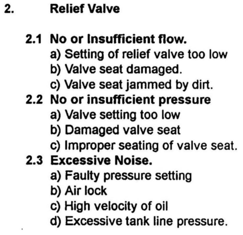
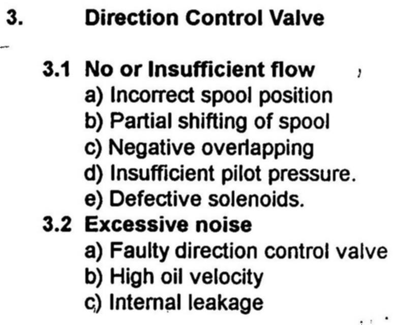
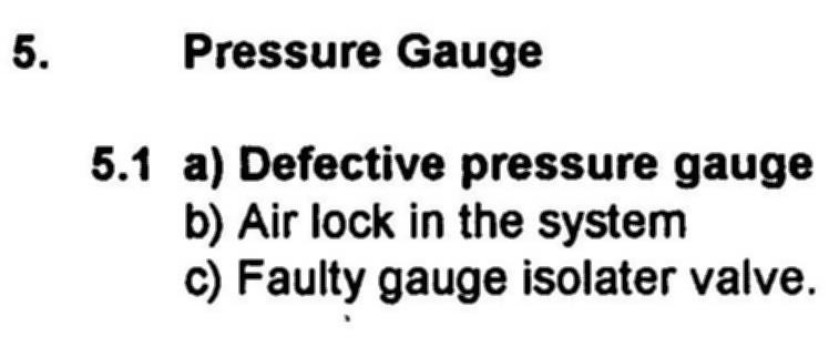
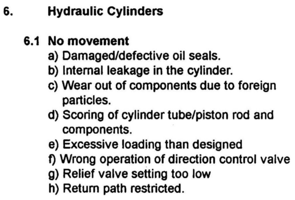
99 BY R. RAMANI SESSION-VII SUBJECT: HYDRAULIC SYSTEM MAINTENANCE TROUBLE SHOOTING, SAFETY, ENVIRNOMENT ISSUES ABOUT THE SESSION This session deals with Hydraulic system maintenance focusing on trouble shooting and safety aspects. INTRODUCTION Possibility of malfunction of various components in the hydraulic system are to be taken care by proper trouble shooting methods. TABLE OF CONTENTS 1. TROUBLE SHOOTING OF THE FOLLOWING: 1. HYDRAULIC PUMP 2. RELIEF VALVE 3. DIRECTION CONTROL VALVE 4. FLOW CONTROL VALVE 5. PRESSURE GAUGE 6. HYDRAULIC CYLINDERS 7. FILTER 8. ELECTRIC MOTOR 2. SAFETY ASPECTS IN HYDRAULICS
100 1. TROUBLE SHOOTING OF THE FOLLOWING:
101
102
103

104 2. SAFETY ASPECTS IN HYDRAULICS
105
Hydraulic Pumps Classification of Pumps
 Fluidsys Training Centre, Bangalore offers an extensive range of skill-based and industry-relevant courses in the field of Pneumatics and Hydraulics. For more details, please visit the website: https://fluidsys.org
CH.4 Basic Components of Hydraulic and Pneumatic System/16 M HAP/17522/AE5G
 Content : 4.1 Hydraulic and Pneumatic actuators. 10 Marks Hydraulic Actuators - Hydraulic cylinders (single, double acting and telescopic) construction and working, Hydraulic motors (gear and piston type)
Test Which component has the highest Energy Density? A. Accumulator. B. Battery. C. Capacitor. D. Spring.
 Test 1 1. Which statement is True? A. Pneumatic systems are more suitable than hydraulic systems to drive powerful machines. B. Mechanical systems transfer energy for longer distances than hydraulic systems.
INTRODUCTION: Rotary pumps are positive displacement pumps. The rate of flow (discharge) of rotary pump remains constant irrespective of the
 of rotary pump remains constant irrespective of the") INTRODUCTION: Rotary pumps are positive displacement pumps. The rate of flow (discharge) of rotary pump remains constant irrespective of the pressure. That is, even at very high pressure, these pumps can
INTRODUCTION: Rotary pumps are positive displacement pumps. The rate of flow (discharge) of rotary pump remains constant irrespective of the pressure. That is, even at very high pressure, these pumps can
Describe the function of a hydraulic power unit
 Chapter 7 Source of Hydraulic Power Power Units and Pumps 1 Objectives Describe the function of a hydraulic power unit and identify its primary components. Explain the purpose of a pump in a hydraulic
MODULE- 5 : INTRODUCTION TO HYDROSTATIC UNITS (PUMPS AND MOTORS)
") MODULE- 5 : INTRODUCTION TO HYDROSTATIC UNITS (PUMPS AND MOTORS) LECTURE- 18 : BASIC FEATURES OF SOME Hydraulic Pumps & Motors Introduction In this section we shall discuss the working principles and fundamental
MODULE- 5 : INTRODUCTION TO HYDROSTATIC UNITS (PUMPS AND MOTORS) LECTURE- 18 : BASIC FEATURES OF SOME Hydraulic Pumps & Motors Introduction In this section we shall discuss the working principles and fundamental
Topic 1. Basics of Oil Hydraulic Systems
 Topic 1. Basics of Oil Hydraulic Systems Fluid power Fluid power is the technology that deals with the generation, control and transmission of forces and movement of mechanical element or system with the
CLOSED CIRCUIT HYDROSTATIC TRANSMISSION
 Energy conservation and other advantages in Mobile Equipment Through CLOSED CIRCUIT HYDROSTATIC TRANSMISSION C. Ramakantha Murthy Technical Consultant Various features/advantages of HST Hydrostatic transmissions
LogSplitterPlans.Com
 Hydraulic Pump Basics LogSplitterPlans.Com Hydraulic Pump Purpose : Provide the Flow needed to transmit power from a prime mover to a hydraulic actuator. Hydraulic Pump Basics Types of Hydraulic Pumps
2. Hydraulic Valves, Actuators and Accessories. 24 Marks
 2. Hydraulic Valves, Actuators and Accessories 24 Marks Co related to chapter 602.2 Describe working principle of various components used in hydraulic & pneumatic systems. 602.3 Choose valves, actuators
Module 5: Valves. CDX Diesel Hydraulics. Terms and Definitions. Categories of Valves. Types of Pressure Control Valves
 Terms and Definitions Categories of Valves Types of Pressure Control Valves Types and Operation of Pressure Relief Valves Operation of an Unloading Valve Operation of a Sequencing Valve Operation of a
speed hydraulic motors. Permission granted to reproduce for educational use only. Contrast the operation of fixed- and variable-
 Chapter 9 Actuators Workhorses of the System 1 Objectives Describe the construction and operation of basic hydraulic cylinders, limited-rotation actuators, and motors. Compare the design and operation
Hydraulic energy control, conductive part
 Chapter 2 2 Hydraulic energy control, conductive part Chapter 2 Hydraulic energy control, conductive part To get the hydraulic energy generated by the hydraulic pump to the actuator, cylinder or hydraulic
FLUID POWER TUTORIAL HYDRAULIC PUMPS APPLIED PNEUMATICS AND HYDRAULICS H1
 FLUID POWER TUTORIAL HYDRAULIC PUMPS This work covers outcome 2 of the Edexcel standard module: APPLIED PNEUMATICS AND HYDRAULICS H1 The material needed for outcome 2 is very extensive so the tutorial
R10 Set No: 1 ''' ' '' '' '' Code No: R31033
 R10 Set No: 1 III B.Tech. I Semester Regular and Supplementary Examinations, December - 2013 DYNAMICS OF MACHINERY (Common to Mechanical Engineering and Automobile Engineering) Time: 3 Hours Max Marks:
Driver Driven. InputSpeed. Gears
 Gears Gears are toothed wheels designed to transmit rotary motion and power from one part of a mechanism to another. They are fitted to shafts with special devices called keys (or splines) that ensure
FLUID POWER FLUID POWER EQUIPMENT TUTORIAL HYDRAULIC AND PNEUMATIC MOTORS. This work covers part of outcome 2 of the Edexcel standard module:
 FLUID POWER FLUID POWER EQUIPMENT TUTORIAL HYDRAULIC AND PNEUMATIC MOTORS This work covers part of outcome 2 of the Edexcel standard module: UNIT 21746P APPLIED PNEUMATICS AND HYDRAULICS The material needed
Nomenclature... xi Hydraulic Laws, Theorems, and Equations...xii
 Nomenclature... xi Hydraulic Laws, Theorems, and Equations...xii 1 Introduction 1.1 Component Design Perspective...1 1.2 Hydraulic Power Evolution...2 1.3 Hydraulic Applications...6 1.4 Component Design
Unit V HYDROSTATIC DRIVE AND ELECTRIC DRIVE
 Unit V HYDROSTATIC DRIVE AND ELECTRIC DRIVE HYDROSTATIC DRIVE In this type of drives a hydrostatic pump and a motor is used. The engine drives the pump and it generates hydrostatic pressure on the fluid.
Theory of Machines. CH-1: Fundamentals and type of Mechanisms
 CH-1: Fundamentals and type of Mechanisms 1. Define kinematic link and kinematic chain. 2. Enlist the types of constrained motion. Draw a label sketch of any one. 3. Define (1) Mechanism (2) Inversion
Lecture 6. Systems review exercise To be posted this weekend Due next Friday (3/6)
") 150 Systems review exercise To be posted this weekend Due next Friday (3/6) Lecture 6 Coming week: Lab 13: Hydraulic Power Steering Lab 14: Integrated Lab (Hydraulic test bench) Topics today: Pumps and
150 Systems review exercise To be posted this weekend Due next Friday (3/6) Lecture 6 Coming week: Lab 13: Hydraulic Power Steering Lab 14: Integrated Lab (Hydraulic test bench) Topics today: Pumps and
Job Sheet 1 Introduction to Fluid Power
 Job Sheet 1 Introduction to Fluid Power Fluid Power Basics Fluid power relies on a hydraulic system to transfer energy from a prime mover, or input power source, to an actuator, or output device (Figure
Radial piston motor for heavy duty wheel drives MCR-W
 Radial piston motor for heavy duty wheel drives MCR-W RE 15200 Edition: 09.2015 Frame size MCR3, MCR5, MCR10 Displacement 160 cc to 1340 cc Differential pressure up to 450 bar Torque output up to 8530
III B.Tech I Semester Supplementary Examinations, May/June
 Set No. 1 III B.Tech I Semester Supplementary Examinations, May/June - 2015 1 a) Derive the expression for Gyroscopic Couple? b) A disc with radius of gyration of 60mm and a mass of 4kg is mounted centrally
Attention is drawn to the following places, which may be of interest for search:
 F01B MACHINES OR ENGINES, IN GENERAL OR OF POSITIVE-DISPLACEMENT TYPE, e.g. STEAM ENGINES (of rotary-piston or oscillating-piston type F01C; of non-positive-displacement type F01D; internal-combustion
LECTURE-23: Basic concept of Hydro-Static Transmission (HST) Systems
 Systems") MODULE-6 : HYDROSTATIC TRANSMISSION SYSTEMS LECTURE-23: Basic concept of Hydro-Static Transmission (HST) Systems 1. INTRODUCTION The need for large power transmissions in tight space and their control
MODULE-6 : HYDROSTATIC TRANSMISSION SYSTEMS LECTURE-23: Basic concept of Hydro-Static Transmission (HST) Systems 1. INTRODUCTION The need for large power transmissions in tight space and their control
LESSON 2 BASIC CONSTRUCTION AND OPERATION OF HYDRAULIC ACTUATING DEVICES, FLOW CONTROL, AND DIRECTIONAL DEVICES. STP Tasks:
 LESSON 2 BASIC CONSTRUCTION AND OPERATION OF HYDRAULIC ACTUATING DEVICES, FLOW CONTROL, AND DIRECTIONAL DEVICES STP Tasks: 552-758-1003 552-758-1071 OVERVIEW LESSON DESCRIPTION: In this lesson you will
KINEMATICS OF MACHINARY UBMC302 QUESTION BANK UNIT-I BASICS OF MECHANISMS PART-A
 KINEMATICS OF MACHINARY UBMC302 QUESTION BANK UNIT-I BASICS OF MECHANISMS PART-A 1. Define the term Kinematic link. 2. Classify kinematic links. 3. What is Mechanism? 4. Define the terms Kinematic pair.
Vickers 45. VMQ Series 30 Vane Pumps. Fixed Displacement, For Industrial and Mobile Applications (4.188)
") [ (4.188) 49,4 (1.94) /21,8 /.86) 174,7/172,3 (6.88/6.78) 332,9/33,5 (13.11/13.1) "M" is marked if metric port threads No marking if inch port threads AS-568-152 O-ring Vickers 45 65,3 (2.57) 13 (5.1 VMQ
[ (4.188) 49,4 (1.94) /21,8 /.86) 174,7/172,3 (6.88/6.78) 332,9/33,5 (13.11/13.1) "M" is marked if metric port threads No marking if inch port threads AS-568-152 O-ring Vickers 45 65,3 (2.57) 13 (5.1 VMQ
Bearings. Rolling-contact Bearings
 Bearings A bearing is a mechanical element that limits relative motion to only the desired motion and at the same time it reduces the frictional resistance to the desired motion. Depending on the design
Definitions of Technical Terms
 Definitions of Technical Terms ABSOLUTE A measure having as it s zero point of base the complete absence of the entity being measured. ABSOLUTE PRESSURE A pressure scale with zero point at a perfect vacuum.
GoTo Europe Focused Delivery Program. Product overview Industrial and Mobile Hydraulics
 GoTo Europe Focused Delivery Program Product overview Industrial and Mobile Hydraulics 2 GoTo Europe You have hardly any time to complete your order before your delivery arrives Nowadays, every day counts
Chapter 2 How the Diesel Aircraft Engine Functions
 Chapter 2 How the Diesel Aircraft Engine Functions People who are familiar with the functioning of a gasoline aircraft engine need not have any difficulty in understanding how a high speed Diesel aircraft
Input, Control and Processing elements
 PNEUMATIC & HYDRAULIC SYSTEMS CHAPTER FIVE Input, Control and Processing elements Dr. Ibrahim Naimi Valves The function of valves is to control the fluid path or the pressure or the flow rate. Depending
three different ways, so it is important to be aware of how flow is to be specified
 Flow-control valves Flow-control valves include simple s to sophisticated closed-loop electrohydraulic valves that automatically adjust to variations in pressure and temperature. The purpose of flow control
CHAPTER 6 GEARS CHAPTER LEARNING OBJECTIVES
 CHAPTER 6 GEARS CHAPTER LEARNING OBJECTIVES Upon completion of this chapter, you should be able to do the following: Compare the types of gears and their advantages. Did you ever take a clock apart to
Module 4: Actuators. CDX Diesel Hydraulics. Terms and Definitions. Cylinder Actuators
 Terms and Definitions Cylinder Actuators Symbols for Actuators Terms and Definitions II Cylinders Providing Linear Motion Cylinders Providing Angular Motion Parts of Actuators Mounting of Actuators Seals
GoTo Europe Focused Delivery Program. Product overview industrial and mobile hydraulics
 GoTo Europe Focused Delivery Program Product overview industrial and mobile hydraulics 2 GoTo Europe The products I need when I need them In today s global competition every day counts. Fast response times
12/25/2015. Chapter 20. Cams. Mohammad Suliman Abuhiba, Ph.D., PE
 Chapter 20 Cams 1 2 Introduction A cam: a rotating machine element which gives reciprocating or oscillating motion to another element (follower) Cam & follower have a line constitute a higher pair. of
Chapter B-3. Chapter 3. Actuators and output devices. Festo Didactic TP101
 155 Chapter 3 Actuators and output devices Festo Didactic TP101 156 An actuator is an output device for the conversion of supply energy into useful work. The output signal is controlled by the control
A pump is a machine used to move liquid through a piping system and to raise the pressure of the liquid.
 What is a pump A pump is a machine used to move liquid through a piping system and to raise the pressure of the liquid. Why increase a liquid s pressure? Static elevation a liquid s pressure must be increased
VB VALVES & AUTOMATION
 Introduction to Valve What are Valves? Valves are mechanical device that controls the flow and pressure within a system or process. They are essential components of a piping system that conveys liquids,
Pumps. Pumps GoTo Europe
 Pumps GoTo Europe 7 Pumps Axial piston pumps Axial piston pumps in swash plate and bent axis design are intended for the medium and high pressure range. Variations in the designs, in the performance ranges
Continuously Variable Transmission
 Continuously Variable Transmission TECHNICAL FIELD The present invention relates to a transmission, and more particularly, a continuously variable transmission capable of a continuous and constant variation
[P F/A] CHAPTER ,' II ' Hydraulic Actuators. cylinders. what cylinders consist of.
![[P F/A] CHAPTER ,' II ' Hydraulic Actuators. cylinders. what cylinders consist of.](/thumbs/82/85096254.jpg "[P F/A] CHAPTER ,' II ' Hydraulic Actuators. cylinders. what cylinders consist of.") CHAPTER 6 Hydraulic Actuators Hydraulic actuators convert hydraulic working energy into mechanical working energy. They are the " intswhere all visible activity takes place and one of ttlls first things
CHAPTER 6 Hydraulic Actuators Hydraulic actuators convert hydraulic working energy into mechanical working energy. They are the " intswhere all visible activity takes place and one of ttlls first things
PISTON MOTORS FOR CLOSED LOOP SYSTEMS types HMF/A/V/R-02
 1-control optional swashing to 0 cc /rev 2-swash plate hydrostatic bearing 3-piston-slipper assembly 21 swash angle 4-housing monoshell for high rigidity 5-valve plate housing highly integrated 6-control
Inner block. Grease nipple. Fig.1 Structure of LM Guide Actuator Model KR
 LM Guide ctuator Model LM Guide + all Screw = Integral-structure ctuator Stopper Housing all screw Inner block Grease nipple Outer rail earing (supported side) Housing Stopper Double-row ball circuit earing
Breakthrough in Linear Generator design
 Breakthrough in Linear Generator design Rotary Linear Generator (stroke-rotor generator) By Physicist Wolfhart Willimczik ABSTRACT The law of inductions demands high speed for the moveable electrical parts,
Radial piston motors for industrial applications MCR-D
 Radial piston motors for industrial applications MCR-D MCR-E RE 15196 Edition: 02.2017 Replaces: 12.2013 MCR-D Frame size MCR3, MCR5, MCR10 Displacement 160 cc to 1340 cc Differential pressure up to 450
Radial piston motor for compact drives MCR-C
 Radial piston motor for compact drives MCR-C RE 15197 Edition: 12.2013 Frame size MCR20 Displacement 1750 cc to 3000 cc Differential pressure up to 450 bar Torque output up to 19099 Nm Speed up to 125
Series 20 Axial Piston Pumps. Technical Information
 Series 20 Axial Piston Pumps Technical Information General Description INTRODUCTION Sauer-Danfoss a world leader in hydraulic power systems has developed a family of axial piston pumps. DESCRIPTION Sauer-Danfoss
DESCRIPTION & OPERATION
 DESCRIPTION & OPERATION BRAKE BOOSTER Delco-Moraine Single Diaphragm A combined vacuum-hydraulic unit which uses a combination of intake manifold vacuum and atmospheric pressure to provide power assist.
Radial piston motor for compact drives MCR-C
 Radial piston motor for compact drives MCR-C RE 15197 Edition: 02.2017 Replaces: 12.2013 Frame size MCR20 Displacement 1750 cc to 3000 cc Differential pressure up to 450 bar Torque output up to 19099 Nm
FRL unit consist of Filterations, Regulators and Lubricator unit.
 4.1 AIR CONTROL 4.1.1 Fluid Conditioner FRL unit consist of Filterations, Regulators and Lubricator unit. It is also known as Air Service Unit. Primary function is to provide clean air at optimal pressure
Hydraulic Pump and Track Motor for Hydrostatic Transmission
 KYB TECHNICAL REVIEW No. 55 OCT. 2017 Product Introduction Hydraulic Pump and Track Motor for Hydrostatic Transmission INADA Takanori, MIURA Takuya, MATSUZAKA Keita 1 Introduction 2 Hydraulic Pumps There
Moments. It doesn t fall because of the presence of a counter balance weight on the right-hand side. The boom is therefore balanced.
 Moments The crane in the image below looks unstable, as though it should topple over. There appears to be too much of the boom on the left-hand side of the tower. It doesn t fall because of the presence
Section 6.1. Implement Circuit - General System. General: TF Configuration TB Configurations Implement Control Valve:
 Section 6.1 Implement Circuit - General System General: TF Configuration... 6.1.3 TB Configurations... 6.1.5 Implement Pump Breakdown... 6.1.6 Operational Description: General... 6.1.7 Compensator Control...
Series 20 Axial Piston Pumps. Technical Information
 Series 20 Axial Piston Pumps Technical Information General Description INTRODUCTION Sauer-Danfoss a world leader in hydraulic power systems has developed a family of axial piston pumps. DESCRIPTION Sauer-Danfoss
Hydrostatic Drive. 1. Main Pump. Hydrostatic Drive
 Hydrostatic Drive The Hydrostatic drive is used to drive a hydraulic motor at variable speed. A bi-directional, variable displacement pump controls the direction and speed of the hydraulic motor. This
All levers are one of three types, usually called classes. The class of a lever depends on the relative position of the load, effort and fulcrum:
 Página 66 de 232 Mechanisms A mechanism is simply a device which takes an input motion and force, and outputs a different motion and force. The point of a mechanism is to make the job easier to do. The
Module 13: Mechanical Fuel Injection Diagnosis and Repair
 Terms and Definitions Parts of Injection Nozzles Types of Nozzle Valves Operation of an Injection Nozzle Fuel Flow Through the Unit Injector Optional Features on Fuel Injection Pumps Main Parts of a Distributor-Type
FRICTION DEVICES: DYNAMOMETER. Presented by: RONAK D. SONI Assistant Professor Parul Institute of Technology, Parul University
 FRICTION DEVICES: DYNAMOMETER Presented by: RONAK D. SONI Assistant Professor Parul Institute of Technology, Parul University DYNAMOMETER A dynamometer is a brake but in addition it has a device to measure
(Refer Slide Time: 1:13)
") Fluid Dynamics And Turbo Machines. Professor Dr Dhiman Chatterjee. Department Of Mechanical Engineering. Indian Institute Of Technology Madras. Part A. Module-2. Lecture-2. Turbomachines: Definition and
Fluid Dynamics And Turbo Machines. Professor Dr Dhiman Chatterjee. Department Of Mechanical Engineering. Indian Institute Of Technology Madras. Part A. Module-2. Lecture-2. Turbomachines: Definition and
ESCONDIDO FIRE DEPT TRAINING MANUAL Section DRIVER OPERATOR Page 1 of 13 Pumps and Accessory Equipment Revised
 DRIVER OPERATOR Page 1 of 13 PUMPS AND ACCESSORY EQUIPMENT Pumps are designed for many different purposes. In order to understand the proper application and operation of a pump in a given situation, firefighters
Series PVP Variable Volume Piston Pumps
 Series PVP Variable Volume Piston Pumps Catalog HY28-2661-CD/US zp2 hpm12-1.p65, lw, jk 1 Notes Series PVP hpm12-1.p65, lw, jk 2 Introduction Series PVP Series Sizes 6-14 Phased Out For Reference Only
Al- Ameen Engg. College. Fluid Machines. Prepared by: AREEF A AP/ ME AL AMEEN ENGINEERING COLLEGE Shoranur.
 Fluid Machines Prepared by: AREEF A AP/ ME AL AMEEN ENGINEERING COLLEGE Shoranur Classification of hydraulic machines HYDROULIC MACHINES (I) Hydraulic Turbines A hydraulic machine which converts hydraulic
Module 6 Assignment Part A
 Module 6 Assignment Part A TOTAL MARKS Part A = 192 TOTAL QUESTIONS Part A = 36 Question 1 [3 Marks] What does pressure refer to in relation to hydrostatics and what is it dependent on? Question 2 [14
AT 2303 AUTOMOTIVE POLLUTION AND CONTROL Automobile Engineering Question Bank
 AT 2303 AUTOMOTIVE POLLUTION AND CONTROL Automobile Engineering Question Bank UNIT I INTRODUCTION 1. What are the design considerations of a vehicle?(jun 2013) 2..Classify the various types of vehicles.
Hydraulic-Training Axial Piston Units
 engineering mannesmann Rexroth Hydraulic-Training Basic Principles RE 90600/01.98 Brueninghaus Hydromatik 1 Basic Principles Page 1.1 Types of 2-3 Hydraulic Circuit 1.1.1 Open circuit 1.1.2 Closed Circuit
Ball. Ball cage. Fig.1 Structure of Caged Ball LM Guide Actuator Model SKR
 Caged all LM Guide Actuator Model Inner block all screw shaft Grease nipple Outer rail all cage all Structure and Features Fig.1 Structure of Caged all LM Guide Actuator Model Caged all LM Guide Actuator
Introduction. General Information. Systems Operation
 Systems Operation Introduction Reference: For illustrated Specifications, refer to the Specifications For 416, 426, 428, 436, 438, & Series II Backhoe Loaders Transmission, Form No. SENR3131. If the specifications
COOPERATIVE PATENT CLASSIFICATION
 CPC F COOPERATIVE PATENT CLASSIFICATION MECHANICAL ENGINEERING; LIGHTING; HEATING; WEAPONS; BLASTING (NOTE omitted) ENGINES OR PUMPS F01 MACHINES OR ENGINES IN GENERAL (combustion engines F02; machines
2. Power Steering System
 2. Power Steering System A: HYDRAULIC SYSTEM POWER STEERING SYSTEM The fluid pump is directly driven by the engine through a belt. The fluid flow is maintained almost constant regardless of change in the
Contents. Index. Content
 s MS motor - Range... 2 MS motor - Torque module... 3 MS motor - Valving cover... 4 MS motor - Multidisc brake... 5 MS motor - Bearing support... 6 MS motor - Drum brake... 7 Forklift truck drive axle...
2. a) What is pantograph? What are its uses? b) Prove that the peaucellier mechanism generates a straight-line motion. (5M+10M)
 What is pantograph? What are its uses? b) Prove that the peaucellier mechanism generates a straight-line motion. (5M+10M)") Code No: R22032 R10 SET - 1 1. a) Define the following terms? i) Link ii) Kinematic pair iii) Degrees of freedom b) What are the inversions of double slider crank chain? Describe any two with neat sketches.
Code No: R22032 R10 SET - 1 1. a) Define the following terms? i) Link ii) Kinematic pair iii) Degrees of freedom b) What are the inversions of double slider crank chain? Describe any two with neat sketches.
Steering unit LAGC. Data sheet
 Steering unit LAGC Data sheet Nominal sizes Series Maximum flow HE 14365 / 09.2017 40 1000 1 x and 2 x 80 l / min 2 LAGC HE 14365 / 09.2017 Page Content 4 4 5 6 7 8 9 10 11 12 13 14 Features Ordering details
CLASSIFICATION OF ROLLING-ELEMENT BEARINGS
 CLASSIFICATION OF ROLLING-ELEMENT BEARINGS Ball bearings can operate at higher speed in comparison to roller bearings because they have lower friction. In particular, the balls have less viscous resistance
Variable Displacement Pump A4VG for closed circuits
 RE 92 003/05.99 RE 92 003/05.99 replaces: 02.98 Variable Displacement Pump A4VG for closed circuits Sizes 28...250 Series 3 Nominal pressure 400 bar Peak pressure 450 bar A4VG...EP Index Features 1 Ordering
Hydraulics. Axial Piston Pumps Series PVP. Introduction. With thru shaft option for multiple pump options Swash plate type for open circuit
 Introduction *not included Pump with standard compensator, code: "omit" With thru shaft option for multiple pump options Swash plate type for open circuit Pump with load sensing, code: "A" Mounting style
Catalog HY /NA. Catalog HY /NA. Parker Hannifin Corporation Hydraulic Pump Division Marysville, Ohio USA
 Catalog HY28-6/NA PV, PVT Series Piston Pumps Variable Volume Catalog HY28-6/NA 1 Catalog HY28-6/NA Notes Series PV 2 Catalog HY28-6/NA Introduction Series PV Quick Reference Data Chart Pump Delivery Approx.
Chapter 13: Application of Proportional Flow Control
 Chapter 13: Application of Proportional Flow Control Objectives The objectives for this chapter are as follows: Review the benefits of compensation. Learn about the cost to add compensation to a hydraulic
Radial piston motor for wheel drives MCR-F
 Radial piston motor for wheel drives MCR-F RE 15198 Edition: 02.2017 Replaces 07.2015 Frame size MCR3, MCR5, MCR10, MCR15 (for frame size 20 see MCR20-C) Displacement 160 cc to 2150 cc Differential pressure
Steering unit LAGZ. Data sheet. Series 2 x
 Steering unit LAGZ Data sheet Nominal sizes 125 620 Series 2 x Maximum flow 50 l / min HE 11868 / 09.2017 2 LAGZ HE 11868 / 09.2017 Page Content 4 4 5 6 7 8 9 10 11 12 13 14 Features Ordering details Function,
Radial piston motor for frame integrated drives MCR-A
 Radial piston motor for frame integrated drives MCR-A RE 15195 Edition: 12.2013 Frame size MCR3, MCR5, MCR10 Displacement 160 cc to 1340 cc Differential pressure up to 450 bar Torque output up to 8530
POWER ASSISTED SYSTEM (POWER STEERING)
") POWER ASSISTED SYSTEM (POWER STEERING) TILT STEERING COLUMN 1. Tilt Steering Column A: TILT MECHANISM The steering wheel vertical position can be adjusted within a 38 mm (1.50 in) range by using the tilt
POWER ASSISTED SYSTEM (POWER STEERING) TILT STEERING COLUMN 1. Tilt Steering Column A: TILT MECHANISM The steering wheel vertical position can be adjusted within a 38 mm (1.50 in) range by using the tilt
B.TECH III Year I Semester (R09) Regular & Supplementary Examinations November 2012 DYNAMICS OF MACHINERY
 Regular & Supplementary Examinations November 2012 DYNAMICS OF MACHINERY") 1 B.TECH III Year I Semester (R09) Regular & Supplementary Examinations November 2012 DYNAMICS OF MACHINERY (Mechanical Engineering) Time: 3 hours Max. Marks: 70 Answer any FIVE questions All questions
1 B.TECH III Year I Semester (R09) Regular & Supplementary Examinations November 2012 DYNAMICS OF MACHINERY (Mechanical Engineering) Time: 3 hours Max. Marks: 70 Answer any FIVE questions All questions
VIS (Valve-In-Star) Hydraulic Motor
 Hydraulic Motor") VIS (Valve-In-Star) Hydraulic Motor VIS 30 Series VIS 40 Series VIS 45 Series The next step in the evolution of low speed high torque (LSHT) hydraulic motors. EATON Low Speed High Torque Motors E-MOLO-MC001-E5
VIS (Valve-In-Star) Hydraulic Motor VIS 30 Series VIS 40 Series VIS 45 Series The next step in the evolution of low speed high torque (LSHT) hydraulic motors. EATON Low Speed High Torque Motors E-MOLO-MC001-E5
Hydraulic drives market trends and offerings
 White Paper Hydraulic drives market trends and offerings S.Krishnakumar Industrial Drives - Hydraulics Eaton India Engineering Center Pune, India Keywords: Hydraulic Drives; Motors; Radial Piston Motor;
ENGINE MECHANICAL <134>
 11A-1 GROUP 11A ENGINE MECHANICAL CONTENTS GENERAL INFORMATION........ 11A-2.................. 11A-3 11A-2 The newly developed 1.1L 134910 engine features 3-cylinder, 12-valve, and double overhead
ROTARY MODULES. Rotary modules
 Rotary modules Rotary modules ROTARY MODULES Series Size Page Rotary modules RM swivel unit 156 RM 08 160 RM 10 162 RM 12 164 RM 15 168 RM 21 172 RM rotor 176 RM 50 180 RM 110 182 RM 200 184 RM 310 186
Radial piston motor for track drives MCR-T
 Radial piston motor for track drives MCR-T RE 15221 Edition: 03.2017 Replaces 07.2015 Frame size MCR5, MCR6, MCR10 Displacement 620cc to 1340cc Differential pressure up to 400 bar Torque output up to 8530
 www.iranfluidpower.com آموزش هیدرولیک N A T I O N A L F L U I D P O W E R A S S O C I A T I O N FLUID POWER TRAINING Basic Hydraulics Course Introduction NFPA is pleased to present the Basic Hydraulics
506E. LM Guide Actuator General Catalog
 LM Guide Actuator General Catalog A LM Guide Actuator General Catalog A Product Descriptions 506E Caged Ball LM Guide Actuator Model SKR.. A2-4 Structure and Features... A2-4 Caged Ball Technology... A2-6
TUTORIAL QUESTIONS FOR THE INDUSTRIAL HYDRAULICS COURSE TEP 4205
 TUTORIAL QUESTIONS FOR THE INDUSTRIAL HYDRAULICS COURSE TEP 4205 The book for the course is Principles of Hydraulic System Design, by Peter J Chapple. Published by Coxmoor Publishing Co., UK. Available
To study the constructional features of ammeter, voltmeter, wattmeter and energymeter.
 Experiment o. 1 AME OF THE EXPERIMET To study the constructional features of ammeter, voltmeter, wattmeter and energymeter. OBJECTIVE 1. To be conversant with the constructional detail and working of common
RV1P /118 ED VARIABLE DISPLACEMENT VANE PUMPS SERIES 10 OPERATING PRINCIPLE TECHNICAL SPECIFICATIONS HYDRAULIC SYMBOL
 14 201/118 ED RV1P VARIABLE DISPLACEMENT VANE PUMPS OPERATING PRINCIPLE TECHNICAL SPECIFICATIONS (measured with mineral oil with viscosity of 46 cst at 40 C) RV1P are variable displacement vane pumps with
Oil Hydraulics Basic Technology Textbook
 Technical education document Oil Hydraulics Basic Technology Textbook DAIKIN INDUSTRIES, LTD. Training Dept. Chapter 1 Basis of Oil Hydraulics CONTENTS 1. Overview of oil hydraulics...1 2. Basic structure
Super Charged Piston Pumps Variable Displacement For Open Circuits. PAVC Medium Pressure
 aerospace climate control electromechanical filtration fluid & gas handling hydraulics pneumatics process control sealing & shielding PAVC Medium Pressure Super Charged Piston Pumps Variable Displacement
Hours / 100 Marks Seat No.
 17412 16117 3 Hours / 100 Seat No. Instructions (1) All Questions are Compulsory. (2) Answer each next main Question on a new page. (3) Illustrate your answers with neat sketches wherever necessary. (4)
(POWER TRANSMISSION Methods)
") UNIT-5 (POWER TRANSMISSION Methods) It is a method by which you can transfer cyclic motion from one place to another or one pulley to another pulley. The ways by which we can transfer cyclic motion are:-
UNIT-5 (POWER TRANSMISSION Methods) It is a method by which you can transfer cyclic motion from one place to another or one pulley to another pulley. The ways by which we can transfer cyclic motion are:-