MONOBLOCK DIRECTIONAL CONTROL VALVES
|
|
|
- Alannah Greer
- 5 years ago
- Views:
Transcription
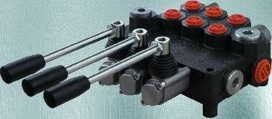
1 MONOBLOCK DIRECTIONAL CONTROL VALVES
2 CONTENTS: RM RM RM40P RM RMD MRP70... Page 1/19&/19 /19...5/19 6/ /19 11/ /19 16/19&17/19 18/19&19/19
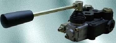
3 MONOBLOCK DIRECTIONAL CONTROL VALVE TYPE RM0 GENERAL DESCRIPTION Document: MDCV-1-Sept 015 Hydraulic valve RM0 provides change of fluid flow direction, hydro-systems pressure restriction, pump unloading in neutral position of the spools. The valve RM0 is designed to be integrated in hydraulic systems of Mobile and Industrial Machines. The valve assembly consists of: A body with integrated relief and check valve, spool, control and spring-centering group of the spool. The valve RM0 provides direct passing of the flow from the pump line to the tank at neutral position (open center). Options closed centre and carry over are possible with additional adapters. There are different control options: spring centering in neutral position, detent, automatic kick-out, hydraulic and electro-hydraulic control. TECHNICAL DATA Rated flow 0 l/min Max. pressure P=50 bar; T=0 bar; A,B= 50 bar Spool stroke ±,5 mm Working temperature range C Working liquid hydraulic oil HLP DIN5154 Liquid viscosity cSt Nominal filtration ISO4406: 19/16 (recommended filter element - 0,05mm mesh) Internal leakage at 10 bar, o t=40 C and viscosity 46cSt max. 8cm³/min; max cm³/min (special version) Actuating force less than 150N Weight 1,7kg DIMENSIONS 1/19
4 MONOBLOCK DIRECTIONAL CONTROL VALVE TYPE RM0 ORDERING CODE RM0 / N / Q / 1 CL A 1 E1 / R / P1T1 / G / N with check valve - omit without check valve - N application N normal T tropical standard port threads P1, T1, T P, A, B G G/8 -A G1/4 -A relief valve setting range bar. (example of required settings 180bar.) shut-off plug installed Q Q180 K P1T1 P1T PT1 used connection ports P1 and T1 P1 and T P and T1 PT P and T spools hydraulic power output 1 R W open center (port P connected to T - short plug) closed center (port T1 plugged - long plug) C carry over (T1 - with power beyond sleeve) 4 1 spool control micro switch: max. current/voltage - 5A/50V AC protection - IP67 contact configuration 5* DIN 4650-A omit without microswitch 7 6 E1 8* * The scheme (spool code 5, 8) needs special body with extra machining and modified cap (C, CL, CLO control) for spool control code 5. 7 lever position A at port side A(standard) B at port side B E E without standard hand lever C o with standard hand lever CL with standard hand lever at 180 CLO with cable control H without lever, with dust-proof plate Z 70 Cables, single levers and joystick controls - on request /19
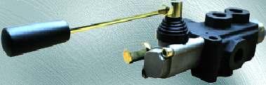
5 MONOBLOCK DIRECTIONAL CONTROL VALVE TYPE RM5 GENERAL DESCRIPTION Hydraulic valve RM5 provides change of fluid flow direction, hydro-systems pressure restriction, pump unloading in neutral position of the spools. The valve RM5 is designed to be integrated in hydraulic systems of Mobile and Industrial Machines. The valve assembly consists of: A body with integrated relief and check valve, spool, control and spring-centering group of the spool. The valve RM5 provides direct passing of the flow from the pump line to the tank at neutral position (open center). There are different control options: spring centering in neutral position, detent, automatic kick-out, hydraulic and electro-hydraulic control. TECHNICAL DATA Rated flow 5 l/min Max. pressure P=50 bar; T=50 bar; A,B= 00 bar Spool stroke ±6 mm Working temperature range C Working liquid hydraulic oil HLP DIN5154 Liquid viscosity cSt Nominal filtration ISO4406: 19/16 (recommended filter element - 0,05mm mesh) Internal leakage at 10 bar, o t=40 C and viscosity 46cSt max. 8cm³/min; max cm³/min (special version) Actuating force less than 00N Weight,kg DIMENSIONS RM5/Q/1CLA1/G/N /19
6 MONOBLOCK DIRECTIONAL CONTROL VALVE TYPE RM5 RM5EHI / N / Q / 1 CL A 1 E1 / G / N ORDERING CODE type of control without control ON-OFF internal electro-hydraulic ON-OFF external electro-hydraulic ON-OFF electropneumatic ON-OFF hydraulic ON-OFF pneumatic omit EHI EHE EPC HC PC spool control standard port threads P, T, A, B M M18x1,5-6H G G/8 -A N T application normal tropical micro switch: max. current/voltage - 5A/50V AC protection - IP67 contact configuration DIN 4650-A with check valve - omit without check valve - N relief valve setting range bar. (example of required settings 180bar.) shut-off plug installed Q Q180 K * omit E1 E without microswitch spools Adjustment range of automatic kick-out feature bar E 1 4* 5* SD1 SD VDC 0-4 4VDC VRAC 0-0VRAC 0-1 1VDC 0-4 4VDC VRAC 0-0VRAC spool control ON-OFF EHI & EHE ON-OFF EPC ON-OFF HC & PC 7 8* A B lever position at port side A(standard) at port side B * The kit (spool control code 11) needs special spool. 9* 10* * The scheme (spool code 4, 5, 8, 9 and 10) needs special body with extra machining. C CL CLO CLR see page / CLS CP H Z 4/19
7 MONOBLOCK DIRECTIONAL CONTROL VALVE TYPE RM5 OPERATION CONTROL without standard hand lever C o with standard hand lever at 180 CLO with standard hand lever CL with stroke (flow) limiter CLR with limit switch CLS with cable control H Cables, single levers and joystick controls - on request with protection cap CP without lever, with dust-proof plate Z 5/19
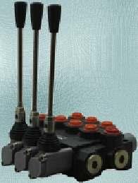
8 MONOBLOCK DIRECTIONAL CONTROL VALVE TYPE RM40P GENERAL DESCRIPTION Hydraulic valve RM40P provides change of fluid flow direction, hydro-systems pressure restriction, pump unloading in neutral position of the spools. The valve RM40P is designed to be integrated in hydraulic systems of Mobile and Industrial Machines. The valve assembly consists of: A body with integrated relief and check valves, spools, control and spring-centering group of the spools. The valve RM40P provides parallel distribution of the working liquid and direct passing of the flow from the pump line to the tank at neutral position (open center). Options closed centre and carry over are possible with additional adapters. There are different control options: spring centering in neutral position, detent, automatic kick-out, hydraulic and electro-hydraulic control. TECHNICAL DATA Rated flow 40 l/min Max. pressure P=50 bar; T=50 bar; A,B= 00 bar Spool stroke ±6 mm Working temperature range C Working liquid hydraulic oil HLP DIN5154 Liquid viscosity cSt Nominal filtration ISO4406: 19/16 (recommended filter element - 0,05mm mesh) Internal leakage at 10 bar, o t=40 C and viscosity 46cSt max. 8cm³/min; max cm³/min (special version) Actuating force less than 00N DIMENSIONS RM40P/0/Q/x/1CLA1/R/P1T1/G/N 6/19
9 MONOBLOCK DIRECTIONAL CONTROL VALVE TYPE RM40P ORDERING CODE RM40PEHI / 0 / Q / 1 CL A 1 E1 / R / P1T1 / G / N * * parallel connection for RM40 - omit type of control without control On-Off internal electro-hydraulic On-Off external electro-hydraulic On-Off electropneumatic On-Off hydraulic omit EHI EHE EPC HC On-Off pneumatic PC common check valve with check valve 0 for RM40 - omit without check valve N 1 R W C standard port threads P1, P A, B T1, T, N M Mx1,5-6H M18x1,5-6H Mx1,5-6H G G1/ -A G/8 -A G1/ -A U 7/8-14UNF-B /4-16UNF-B 7/8-14UNF-B G1/ G1/ -A hydraulic power output open center (port N connected to T - short plug) closed center (port N plugged - long plug) carry over (port N - with power beyond sleeve) spool control P1T1 P1T PT1 PT application N T P1 and T1 normal tropical used conn. ports P1 and T P and T1 P and T micro switch: max. current/voltage - 5A/50V AC protection - IP67 contact configuration number of the spools for RM40 - omit relief valve setting range bar (example of required settings 180bar) shut-off plug installed Q Q180 K omit E1 without microswitch DIN 4650-A spools 7 E E 10 spool control 4 11* Adjustment range of automatic kick-out feature bar 0-1 1VDC 0-4 4VDC VRAC 0-0VRAC ON-OFF EHI & EHE VDC 0-4 4VDC VRAC 0-0VRAC ON-OFF HC & PC ON-OFF EPC 8* 16 SD1 9 10* 11* * The scheme (spool code 8, 10 and 11) needs special body with extra machining. 17 C CL CLO CLR see page /5 CLS CP H Z J... see page 4/5 A B SD10 lever position * The kit (spool control code 11) needs special spool. at port side A (standard) at port side B ** Repeat for each spool. In case of identical spools example ordering code is: RM40P / 0 / Q / x / 1CL A1 / R / P1T1 / G / N 7/19
10 MONOBLOCK DIRECTIONAL CONTROL VALVE TYPE RM40P OPERATION CONTROL without standard hand lever C o with standard hand lever at 180 CLO with standard hand lever CL with stroke (flow) limiter CLR with limit switch CLS with cable control H Cables, single levers and joystick controls - on request with protection cap CP without lever, with dust-proof plate Z 8/19
11 MONOBLOCK DIRECTIONAL CONTROL VALVE TYPE RM40P OPERATION CONTROL Working scheme by assembly on the side of threaded ports A (standard) J1... J... J4... joystick with standard hand lever joystick without standard hand lever : J1L ; JL ; JL ; J4L : J1 ; J ; J ; J4 M10 9/19
12 MONOBLOCK DIRECTIONAL CONTROL VALVE TYPE RM40P RM40PEHI/0/Q/x/1CLA0-4/R/P1T1/G/N On/Off electrohydraulic control (internal) operating features: Pilot pressure bar Max. pilot flow - 8 l/min Filtration - 5 mm Coil - 18W, duty cycle ED 100% Voltage options - 1V DC, 4V DC, 110V RAC, 0V RAC Integrated back pressure valve RM40PEHE/0/Q/x/1CLA0-4/R/P1T1/G/N On/Off electrohydraulic control (external) operating features: Pilot pressure Pp bar Max. pilot flow - 8 l/min Filtration - 5 mm Coil - 18W, duty cycle ED 100% Voltage options - 1V DC, 4V DC, 110V RAC, 0V RAC Pp, Tp - G1/4 10/19
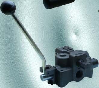
13 MONOBLOCK DIRECTIONAL CONTROL VALVE TYPE RM80 GENERAL DESCRIPTION Hydraulic valve RM80 provides change of fluid flow direction, hydro-systems pressure restriction, pump unloading in neutral position of the spools. The valve RM80 is designed to be integrated in hydraulic systems of Mobile and Industrial Machines. The valve assembly consists of: A body with integrated relief and check valves, spools, control and spring-centering group of the spools. The valve RM80 provides parallel distribution of the working liquid and direct passing of the flow from the pump line to the tank at neutral position (open center). Options closed centre and carry over are possible with additional adapters. There are different control options: spring centering in neutral position, detent, automatic kick-out, hydraulic and electro-hydraulic control. TECHNICAL DATA Rated flow 80 l/min Max. pressure P=50 bar; T=50 bar; A,B= 00 bar Spool stroke ±7 mm Working temperature range C Working liquid hydraulic oil HLP DIN5154 Liquid viscosity cSt Nominal filtration ISO4406: 19/16 (recommended filter element - 0,05mm mesh) Internal leakage at 10 bar, o t=40 C and viscosity 46cSt max. 8cm³/min; max cm³/min (special version) Actuating force less than 80N DIMENSIONS RM80P//Q/x/1CLA1/R/P1T1/G/N 11/19
14 MONOBLOCK DIRECTIONAL CONTROL VALVE TYPE RM80 ORDERING CODE RM80PEHI / / Q / 1 CL A 1 E1 / R / P1T1 / G / N * * type of connection for RM80 Parallel Series* Tandem (P+S)* type of control without control On-Off internal electro-hydraulic On-Off external electro-hydraulic On-Off electropneumatic On-Off hydraulic omit * The scheme (connection type S and T) needs special body. P S T omit EHI EHE EPC HC On-Off pneumatic PC 1 R W C standard port threads P1, P, A, B T1, T, N M Mx1,5-6H M6x1,5-6H G G1/ -A G/4 -A U 7/8-14UNF-B 1 1/16-1UN-B hydraulic power output open center (port N connected to T - short plug) closed center (port N plugged - long plug) carry over (port N - with power beyond sleeve) spool control application N T P1T1 P1T PT1 PT normal tropical used conn. ports P1 and T1 P1 and T P and T1 P and T micro switch: max. current/voltage - 5A/50V AC protection - IP67 contact configuration number of the spools for RM80 - omit relief valve setting range bar Q (example of required settings 180bar) Q180 shut-off plug installed K omit E1 without microswitch DIN 4650-A spools 7 E * E Adjustment range of automatic kick-out feature bar 0-1 1VDC 0-4 4VDC VRAC 0-0VRAC spool control ON-OFF EHI & EHE VDC 0-4 4VDC VRAC 0-0VRAC ON-OFF HC & PC ON-OFF EPC 8* * The kit (spool control code 11) needs special spool. 9* 10 * The scheme (spool code 8 and 9) needs special body with extra machining. C CL CLO CLR see page /5 CLS CP H Z J... see page 4/5 A B lever position at port side A (standard) at port side B ** Repeat for each spool. In case of identical spools example ordering code is: RM80 / / Q / x / 1CL A1 / R / P1T1 / G / N 1/19
15 MONOBLOCK DIRECTIONAL CONTROL VALVE TYPE RM80 OPERATION CONTROL without standard hand lever C o with standard hand lever at 180 CLO with standard hand lever CL with stroke (flow) limiter CLR with limit switch CLS with cable control H Cables, single levers and joystick controls - on request with protection cap CP without lever, with dust-proof plate Z 1/19
16 MONOBLOCK DIRECTIONAL CONTROL VALVE TYPE RM80 OPERATION CONTROL Working scheme by assembly on the side of threaded ports A (standard) J... J1... J... J4... joystick with standard hand lever joystick without standard hand lever : J1L ; JL ; JL ; J4L : J1 ; J ; J ; J4 M10 14/19
17 MONOBLOCK DIRECTIONAL CONTROL VALVE TYPE RM80 RM80PEHI/4/Q/4x/1CLA0-4/R/P1T1/G/N On/Off electrohydraulic control operating features: (internal) Pilot pressure bar Max. pilot flow - 8 l/min Filtration - 5 mm Coil - 18W, duty cycle ED 100% Voltage options - 1V DC, 4V DC, 110V RAC, 0V RAC Integrated back pressure valve 15/19
18 MONOBLOCK DIRECTIONAL CONTROL VALVE TYPE RMD90 GENERAL DESCRIPTION The directional control valve RMD90 provides a change of fluid flow direction in the channels of the hydraulic system. Valve RMD90 is designed for mounting in the hydraulic systems of the mobile and industrial machines. TECHNICAL DATA Weight 5.7kg Nominal flow 90 l/min Maximal flow 150 l/min Nominal pressure 16 MPa Maximal pressure 0 MPa Working stroke of the spool ±8 mm Spool leakage at p=100bar o t=40 C and viscosity 6cSt 5 cm /min Working fluid-hydraulic oil with parameters: viscosity cSt recommended viscosity cSt o temperature C degree of filtration - 0,05mm DIMENSIONS 16/19

19 MONOBLOCK DIRECTIONAL CONTROL VALVE TYPE RMD90 ORDERING CODE RMD90-1 DL 1 G Double acting, position, 4 way A and B blocked in neutral 1 G K P, T, A, B G/4 -A K/4-14 GOST (/4-14NPT) Double acting, position, 4 way A, B and P to tank in neutral 1 Spring return to neutral Double acting, position, 4 way A and B to tank in neutral Detent in position 1 and Lever : with lever DL without lever D Detent in three positions 17/19
20 MONOBLOCK DIRECTIONAL CONTROL VALVE TYPE MRP70 GENERAL DESCRIPTION 1. The valve type MRP 70 incorporates the features of a 4-way directional control valve, an adjustable full range pressure compensated by-pass type flow control valve and a pilot operated pressure relief valve all in one compact package.. Less fittings and plumbing, eliminates leakage points.. Fine positive metering is possible in either direction with one manually adjustable, infinitely variable lever controlling both direction and amount of flow. Amount of flow is proportional to movement of the lever. 4. Flow is constant regardless of pressure variations, thus flow out the work port remains smooth and constant regardless of changes in load conditions. 5. An externally adjustable pilot relief is standard. 6. Friction detent (Friction positioner kit). Hydraulic scheme: Rated flow l/min (US GPM) 70 (18) Rated pressure bar (PSI) 10 (000) Standard port size: DATA Inlet & outlet work ports A & B TECHNICAL DATA Working liquid - hydraulic oils with parameters: -viscosity mm /sec (cst) recommended viscosity mm /sec (cst) temperature o o C ( F) ( ) -degree of filtration mm (in) ( ) Leakage at p=100bar cc/min 15 t=40oc ; 6cSt UNIT BSP BSP VALUE/RANGE /4 ½ 18/19
21 MONOBLOCK DIRECTIONAL CONTROL VALVE TYPE MRP70 PERFORMANCE CURVE 100 Neutral Flow Pressure Drop CONDITIONS:? P=f(Q) 6 cst oil viscosity T=40 C(104 F) Flow [GPM] In this curve the pressure difference between the inlet and outlet is shown. DIMENSIONS All dimensions are in mm (in). A 54(.1) 85(.1) 81(.15) Pressure[PSI] 100(.9) 185(7.1) A 19/19
22 BULGARIA JOINT-STOCK COMPANY BULGARIA, 6100 KAZANLAK, 45 STOLETOV Str. Tel.:+59/41/6 9, +59/41/61, Fax:+59/41/6 0, +59/41/6 14 WEB:
Auxiliary valves. Lever. Spool positioner Check valve Spool
 Auxiliary valves Lever Spool positioner Check valve Spool CONTENTS: Page -Technical data... 1 -Dimensions RP80... 2 -Dimensions RP60... 3 -Lever mechanism... 4 -Spools/spool control... 5 -Inlet cover/outlet
-Technical data... 2/14 -Circuit mode... 2/14 -Dimensions RP /14
 Auxiliary valves Document: SCV-1-June 2013 Lever Spool positioner Check valve Spool CONTENTS: Page -Technical data... 2/14 -Circuit mode... 2/14 -Dimensions... 3/14 -Dimensions... 4/14 -Lever mechanism...
Available manual, pneumatic, and hydraulic spool control kits.
 Fitted with a main pressure relief valve and a load check valve on every working section. Available with parallel circuit. Optional carry-over Variety of port valves (auxiliary valves) Available manual,
DIRECTIONAL CONTROL VALVES CETOP3
 DIRECTIONAL CONTROL VALVES CETOP3 CONTENTS: RH06...1 - electrical control... RH06...2 - hydraulic control... Page 1/17...7/17 8/17...9/17 RH06...4 - mechanical control RH06...6 - pneumatic control......
Monobloc and Sectional Directional Control Valves
 Monobloc and Sectional Directional Control Valves motion and progress 1/220 6 Monobloc directional control valves Contents 6.1 General specifications 66 6.2 Dimensional data 67 6.3 Performances curves
HYDRAULICS VINCKE DIRECTIONAL CONTROL VALVES
 VINCKE DIRECTIONAL CONTROL VALVES TECH-DCV200.1 index 3 link to your page / link a su página Monoblock hydraulic distributors Monoblock hydraulic distributors 35 liters 3 P35 Monoblock hydraulic directional
SECTIONAL DIRECTIONAL VALVE HDS 20 SERIES. CROSS HYDRAULICS PTY LTD YELLOW CATALOGUE Page 3.84
 CROSS HYDRAULICS PTY LTD YELLOW CATALOGUE Page 3.84 Material specification: Standard features: Optional features available: Symbols: P T A/B H.P.C.O. RV P 1 T 1 Weight CROSS HYDRAULICS PTY LTD YELLOW CATALOGUE
DIRECTIONAL CONTROL VALVES CETOP3
 DIRECTIONAL CONTROL VALVES CETOP3 GENERAL DESCRIPTION RH0...1-...F... Document: DCVC3-1-Aug 2013 4/3- and 4/2- way directional control valves with solenoid operation, heavy duty construction RH0...1-...F...
SECTIONAL DIRECTIONAL VALVE HDS 30 SERIES. CROSS HYDRAULICS PTY LTD YELLOW CATALOGUE Page 3.106
 CROSS HYDRAULICS PY LD YELLOW CAALOGUE Page 3.106 Material specification: Standard features: Optional features available: Symbols: P A/B H.P.C.O. RV P 1 1 Weight CROSS HYDRAULICS PY LD YELLOW CAALOGUE
Contents. Directional Control Valve 3 Series CV 452. Page 3-4. General Information. Page 5. Technical data. Page 6. Performance Curves.
 Contents Page 3-4 Page 5 Page 6 Page 7 Page 8 Page 9 Page 10 Page 11 Page 12 Page 13 Page 14 General Information Technical data Performance Curves Dimensions - Basics Valve Dimensions - LS Valve Secondary
Monoblock directional control valves DL - Directional control valve
 Monoblock directional control valves DL - Directional control valve DL Before use, carefully read the GENERAL INSRUCIONS FOR USE OF DIRECIONAL CONROL VALVES 398SMD008I00-06-2-208 DL echnical data Nominal
NB: models, Codes and Specifications may be subject to change without notice. SECTION A DIRECTIONAL CONTROL VALVES MANUAL DIRECTIONAL VALVES
 NB: models, Codes and Specifications may be subject to change without notice. SECTION A DIRECTIONAL CONTROL VALVES MANUAL DIRECTIONAL VALVES Valve Series Page...... A 2 WALVOIL FRONT-END LOADER VALVES...
MDT. Monoblock directional control valves MDT - Directional control valve
 Monoblock directional control valves - Directional control valve efore use, carefully read the GENERL INSRUCIONS FOR USE OF DIRECIONL CONROL VLVES echnical data Nominal flow 35 l/min 9. US gpm Nominal
Monoblock Directional Control Valve PMB22TSTSAB PMB23TSTSTSLB PMB21TDLB
 Engineering & Manufacturing Solutions Specifications: FLOW RATINGS: - MB21 & MB22 10 gpm (38 lpm) - MB23 8 gpm (30 lpm) Rated up to 4000 psi (275 bar). Port Sizes: - Inlet/Outlet #8 SAE. -Work Ports #8
Directional Control Valve CV550
 www.nimco-controls.com Directional Control Valve CV550 Smart Solutions... for the Future Contents Page 5 Page 6 Page 7 Page 8 Page 9 Page 10 Page 11 Page 12 Page 13 Page 14 Page 16 Page 17 Page 18 Page
Monoblock Directional Control Valve RM 230
 Monoblock Directional Control Valve RM 230 Key valve features RM 230 light is a monoblock valve, designed for max. operating pressures up to 3,000 psi (210 bar) and typ. pump flows up to 20 gpm (70 Lpm).
ORV-M45. Contents. Additional Informations
 Contents Working Conditions 3 Dimensional Data 4 Hydraulic Circuit 5 Performance Data And Curve 7 Inlet Relief Options 8 Ordering Codes 9 Spool Options 11 Spool Positioners Side of Return 14 Spool Positioners
SECTION A FRONT END LOADER VALVES
 NB: models, Codes and Specifications may be subject to change without notice. SECTION A FRONT END LOADER VALVES Valve Series Nominal PAGE WALVOIL FRONT-END LOADER VALVES SDM102 Series... 45L/Min... A 14
Sectional Directional Control Valve RS 220
 Sectional Directional Control Valve RS 0 RS 0 is a sectional open center valve designed for max. operating pressures up to 00 bar and max. pump flows up to 0 l/min. Technical data Pressure and flow values*
Contents. Directional Control Valve 2 Series CV Unibody. Page 3-4. General Information. Page 5. Technical data. Page 6. Performance Curves
 Contents Page 3-4 Page 5 Page 6 Page 7 Page 8 Page 9 Page 10 Page 11-12 Page 13 Page 14 Page 15 General Information Technical data Performance Curves Dimensions - Basic Valve Dimensions - Unibody Secondary
4-Way Directional Control With Pressure Compensated Flow Control PSDCF120M64LF Specifications:
 Engineering & Manufacturing Solutions With Pressure Compensated Flow Control Specifications: Rated for 0-18 gpm (0-68.1 lpm) Rated for 3000 psi (207 bar) Weighs 6-1/2 lbs. (2.9 kg) 30 Micron filtration
COMPACT CATALOG MONOBLOCK DIRECTIONAL CONTROL VALVES
 COMAC CAALOG MONOBLOCK DIRECIONAL CONROL VALVES SD4 Features Simple, compact designed, this valves is only one section for open center and closed center hydraulic systems. H Fittedwithamainpressurereliefvalve.
4-Way Directional Control Valve With Hydraulic Kick Out
 Engineering & Manufacturing Solutions 4-Way Directional Control Valve With Hydraulic Kick Out Specifications: Rated for 0-18 gpm (0-68.1 lpm) Rated for 3000 psi (207 bar) Weighs 5-1/2 lbs. (2.5 kg) 30
Sectional Directional Control Valve RSQ 240
 Sectional Directional Control Valve RSQ 0 Key valve features RSQ 0 is a sectional open center valve, designed for max. operating pressures up to 50 bar and max. pump flows up to 00 l/min. It is available
V250 SERIES DIRECTIONAL CONTROL VALVES
 V SERIES DIRECTIONAL CONTROL VALVES TAKE CONTROL OF YOUR HYDRAULICS Take control with Muncie Power Products V directional control valve. The V is constructed with high-grade iron castings and nickel-plated
NV452 Monoblock directional control valve
 NV452 Monoblock directional control valve Product Features General Specifications Order Coding Open Center Load Sense Performance Data Inlet Options Spool Positioners Spool Options Auxilary Valves Lever
DC Series. 4-Way Directional Control Valve With Or Without Flow Control PDC16T4PBS PDCF16TM454LF
 Engineering & Manufacturing Solutions Specifications: Rated for 0-45 gpm (0-170 lpm) Rated for 3000 psi (207 bar) Std. port sizes (Consult factory for others) - 3/4 NPT all ports - #16 SAE (1-5/16-12)
Symbol RH F... GENERAL DESCRIPTION. 4/3- and 4/2- way directional control valves with solenoid operation, heavy duty construction
 GENERAL DESCRIPTION List: RH06-1F-1-July 016 4/3- and 4/- way directional control valves with solenoid operation, heavy duty construction Removable AC and DC voltage coils-quick replacement and rotation
Directional Control Valve Series 4D01 (DENISON)
") Characteristics The Denison series 4D01 is a solenoid operated directional control valve size NG06 in -chamber design. It is direct operated by wet pin solenoids. The 4D01 is available with a Soft Shift
Characteristics The Denison series 4D01 is a solenoid operated directional control valve size NG06 in -chamber design. It is direct operated by wet pin solenoids. The 4D01 is available with a Soft Shift
Contents. Directional Control Valve 2 Series CV 300
 Contents Page 3 General Information Page 4 Technical data Page 5 Dimensions Page 6 Secondary Valves Page 7 Cylinder port mounted secondary valves Page8 Spool - Control characteristics Page 9-10 Spool Controls
COMPACT CATALOG MONOBLOCK DIRECTIONAL CONTROL VALVES
 COMAC CAALOG MONOBLOCK DIRECIONAL CONROL VALVES Features Simple, compact designed, this valve is only one section for open center and closed center hydraulic systems. H Fitted with a main pressure relief
V050 SERIES DIRECTIONAL CONTROL VALVE
 V5 SERIES DIRECTIONAL CONTROL VALVE TAKE CONTROL Take control with Muncie Power Products V5 directional control valve. The V5 is constructed with high-grade iron castings and nickel-plated spools for use
HYDRAULIC CONTROL VALVES
 HYDRAULIC VALVES SECTION 3A HYDRAULIC CONTROL VALVES MONOBLOCK DIRECTIONAL CONTROL VALVES...71 SLICE DIRECTIONAL CONTROL VALVES...73 HANDLEVERS...76 S additions for valves...76 VALVE CONTROL KITS additions
Pilot-Operated Directional Control Valves Series D3 - D11
 Catalogue HY11-500/UK Characteristics The D31, D41, D81, D91 and D111 are electrical controlled 4/3 or 4/ way directional control valves. The valves are pilot-operated by an NG6 valve. Pressure and flow
Chapter 5: Flow Valves
 Catalogue HY11-300/UK Contents Chapter : Flow Valves Series Description Size Mounting Page Parker Standard DIN / ISO 1/4 3/8 1/2 3/4 1 06 10 16 Throttle valves, manual adjustment MVI -2 NS -4 FS With free
Hydro M t HYDRAULIC VALVES SN-4.
 Hydro HYDRAULI VALVES A SRONG OMMIMEN O QUALIY Our concept is to sell and deliver the best quality of hydraulic valves, that fully meet our customer s rigorous requirements! o this end, our quality control
Pilot control unit with end position lock for the remote control of directional valves
 Pilot control unit with end position lock for the remote control of directional valves RE 64 553/02.07 1/12 Replaces : 05.05 Type 4THF6 or 5THF6 Series 2X Contents Functional description, section, symbol
MONO-BLOCK DIRECTIONAL VALVE HDM 18 SERIES
 Material specification: Standard features: Optional features available: Symbols: A/B H..C.O. RV 1 1 Weight CROSS HYDRAULICS Y LD YELLOW CAALOGUE age 2.45 HDM18/1 1 H..C.O. A B 1 RV HDM18/2/3/4 B B A A
Commercial Shearing (Pty) Ltd THE WORLDWIDE PROGRAM OF VALVES ISO 9001
 Ltd THE WORLDWIDE PROGRAM OF VALVES ISO 9001") Commercial Shearing (Pty) Ltd THE WORLDWIDE PROGRAM OF VALVES ISO 9001 An Insight into Valve Technology CLEAN ROOM ASSEMBLY AND TEST A major investment has been made in a clean-room assembly and test environment.
Commercial Shearing (Pty) Ltd THE WORLDWIDE PROGRAM OF VALVES ISO 9001 An Insight into Valve Technology CLEAN ROOM ASSEMBLY AND TEST A major investment has been made in a clean-room assembly and test environment.
mechanical control valve
 DF Working conditions This catalogue shows technical specifications and diagrams measured with mineral oil of 46 mm /s -- 46 cst viscosity at 4 C temperature. DF5 DF DF DF5 N. of available ways --3--6
MONOBLOCK DIRECTIONAL CONTROL VALVES
 MONOBLOCK VALVE INDEX MONOBLOCK DIRECTIONAL CONTROL VALVES For mobile and industrial hydraulic applications. MA6 (6 GPM) General Specifications 4 Dimensions 5 Performance Chart 6 Ordering Code 7 MAV12
Flow sharing control block in mono block / sandwich plate design M6-15
 Flow sharing control block in mono block / sandwich plate design M6-15 RE 64321 Edition: 01.2015 Replaces: 05.2012 Size 15 Series 3X Maximum operating pressure on pump side 350 bar on consumer side 420
Directional Control Valve Series D3W (Parker), 4D02 (Denison)
, 4D02 (Denison)") Characteristics Series D3W (Parker), 4D0 (Denison) The direct operated directional control valve size NG10 is available with both Parker (series D3W) and Denison (series 4D0) model codes. Both series are
Characteristics Series D3W (Parker), 4D0 (Denison) The direct operated directional control valve size NG10 is available with both Parker (series D3W) and Denison (series 4D0) model codes. Both series are
COMPACT CATALOGUE SECTIONAL DIRECTIONAL CONTROL VALVES
 COMAC CAALOGUE SECIONAL DIRECIONAL CONROL VALVES SDS5 Features Simple, compact and heavy duty designed sectional valve from to sections for open and closed centre hydraulic systems. H Fitted with a main
Umschaltventile DF20/3. mit Hebel Bestellnr. Typ Code
 Umschaltventile DF/3 Bestellnr. Typ Code mit Hebel 4-- DF/3AL 64 4-- DF/3A7L 6744 4-- DF/3A7SLP 64 4-- DF/3AT7SLP 64 4-- DF/3BC7CB 674 4-- DF/3AC7CA-TAP(A) 64 4--3 DF/3B7MEIA-TAP(B) 648 4--4 DF/3AMB 6
Hand-operated Hydraulic Control Valve 4- way 2-position 4 Ports
 Hand-operated Hydraulic Control Valve 4- way 2-position 4 Ports Hydraulic Directional Valve P40 2 Spool 4 Way 3 Position Chief 220907. $137.00 Prince Hydraulic Compensated Flow Control RD-175-30 3/4" Port
Monobloc and Sectional Directional Control Valves
 Monobloc and Sectional Directional Control Valves motion and progress 1/220 10 Sectional directional control valves HDS20 Contents 10.1 General specifications 177 10.2 Dimensional data 178 10.3 erformances
Directional control valve / RM 270
 Directional control valve / 31-02-RM270-05 Nordhydraulic AB P.O Box 189 (Industrivägen 15) SE-872 24 KRAMFORS Sweden Solutions that power your visions Telephone: Int. +46 612 71 72 00 Telefax: Int. +46
Pilot Operated Directional Control Valves Series D31DW, D41VW - D111VW
 Characteristics The D31, D41, D81, D91 and D111 are electrically controlled 4/3 or 4/ way directional control valves. The valves are pilot operated by an NG6 valve. Pressure and flow of the pilot oil have
LOAD SENSE SECTIONS. Series 20. Directional Control Valves NEED NEW PIC VALVES STANDARD FEATURES SPECIFICATIONS
 Directional Control Valves LOAD SENSE SECTIONS NEED NEW PIC Series 20 STANDARD FEATURES Control and reduced Dead Band (20I) and Tie Rod Kits SPECIFICATIONS Pressure Rating Foot Mounting Maximum Operating
Pilot Operated Pressure Relief Valve Series R5V (Denison)
") Characteristics Pilot operated pressure relief valves series R5V have a similar design to the subplate mounted R4V series. The SAE flanges allow to mount the valves directly on the outlet flanges of pumps
Characteristics Pilot operated pressure relief valves series R5V have a similar design to the subplate mounted R4V series. The SAE flanges allow to mount the valves directly on the outlet flanges of pumps
Monobloc and Sectional Directional Control Valves
 Monobloc and Sectional Directional Control Valves 200 P 991210 E 03 / 10.04 1/220 2 Monobloc directional control valves HDM140 Contents 2.1 General specifications 9 2.2 Dimensional data 10 2.3 Performances
Selector Valve RV 713
 Selector Valve RV 713 Key valve features RV 713 is a 3 way selector valve designed for flows up to 42gpm (160 Lpm) and max. operating pressures up to 3,625 psi (250 bar). Spools, both 2 and 3 position,
BW0511FP. ByWire Elements BW0511FP Flow Sharing Element Interface IBW0511
 ywire Elements Flow Sharing Element Interface IW05 efore use, carefully read the GENERL INSTRUCTIONS FOR USE OF DIRECTIONL CONTROL VLVES Technical data Nominal flow Nominal pressure 35 l/min - P=8 bar
DMH085** Series will be available January 1, Catalog HY /US SERIES CAVITY DESCRIPTION FLOW PRESSURE PAGE NO.
 Catalog HY-/US Contents SERIES CAVITY DESCRIPTION FLOW PRESSURE PAGE NO. /GPM BAR/PSI DL8... C8-... Position, Way, N.C. Poppet,... Pull to Open.../8... /... DL... C-... Position, Way, N.C. Poppet,... Pull
Pilot Operated Directional Control Valves Series D1VP, D3DP, D4P, D9P, D11P
 Characteristics Series D1VP, D3DP, D4P, D9P, D11P The D1VP is a hydraulically controlled 4/3 or 4/ way directional control valve. The valve can be operated either by the pilot ports X and Y via the subplate
Flow sharing control block in mono block / sandwich plate design M6-22
 Flow sharing control block in mono block / sandwich plate design M6-22 RE 64322 Edition: 01.2015 Replaces: 05.2012 Size 22 Series 3X Maximum operating pressure on pump side 350 bar on consumer side 420
COMPACT CATALOGUE SECTIONAL DIRECTIONAL CONTROL VALVES
 COMAC CAALOGUE SECIONAL DIRECIONAL CONROL VALVES Features Simple, compact and heavy duty designed sectional valve from to sections for open and closed centre hydraulic systems. H Fitted with a main pressure
Section 1-7. Nominal Flow 50 lpm 13 US gpm. Threads G3/8 (Standard) SAE8
 SAE8") Valve is equipped with an adjustable main relief valve, available in parallel circuit, wide range of spool options and positioners, interchangable spools Manual and remote cable Section 1 Weight 2,1 kg
Valve is equipped with an adjustable main relief valve, available in parallel circuit, wide range of spool options and positioners, interchangable spools Manual and remote cable Section 1 Weight 2,1 kg
Directional control valve HV07 Constant flow and constant pressure valve. Catalogue (GB) Catalogue (US) October 1998
 Catalogue (US) October 1998") Directional control valve Constant flow and constant pressure valve Catalogue 9129 8539-02 (GB) Catalogue 9129 8539-06 (US) October 1998 Catalogue layout This catalogue has been designed to give an overview
Directional control valve Constant flow and constant pressure valve Catalogue 9129 8539-02 (GB) Catalogue 9129 8539-06 (US) October 1998 Catalogue layout This catalogue has been designed to give an overview
TPV Variable Displacement Closed Loop System Axial Piston Pump THE PRODUCTION LINE OF HANSA-TMP HT 16 / M / 852 / 0815 / E
 HYDRAULIC COMPONENTS HYDROSTATIC TRANSMISSIONS GEARBOXES - ACCESSORIES Certified Company ISO 9001-14001 ISO 9001 Via M. L. King, 6-41122 MODENA (ITALY) Tel: +39 059 415 711 Fax: +39 059 415 729 / 059 415
Directional Control Valve
 Characteristics The NG6 directional control valve series D1VW provides high functional limits up to 8 l/min in combination with a very low, energy-saving pressure drop. wide variety of spool options allows
Post-Compensated Proportional Valve CV2000LS
 www.nimco-controls.com Post-Compensated Proportional Valve CV2000LS Smart Solutions... for the Future Contents Page 5 Page 6 Page 7 Page 8 Page 9 Page 10 Page 11 Page 12 Page 13 Page 14 Page 15 Page 16
HYDRAULIC PILOT CONTROL UNIT OF SANDWICH PLATE DESIGN
 01 /10 2.2 HYDRULIC PILOT CONTROL UNIT OF SNDWICH PLTE DESIGN Type: H*-2TH6 Benefits: Progressive, sensitive control Precise and play-free control characteristics Low actuation force at the lever Rust-free
6/2 ways/positions flow diverters
 6/2 ways/positions flow diverters RE 18302-07/07.12 Replaces: 12.09 1/8 L753... (VS311-VS312-VS315) Size 10 Series 00 Maximum operating pressure 310 bar [4500 psi] Maximum flow 140 l/min [36,98 gpm] Ports
HYDRAULICS VINCKE INDUSTRIAL HYDRAULIC VALVES
 VINCKE INDUSTRIAL HYDRAULIC VALVES TECH-VIHV-200.1 index 3 link to your page / link a su página 4VNKSV Directional on/off control 4 3 CETOP 3 3 CETOP 5 7 10 4VNKEH Electro-hydraulic directional control
Pressure Control Valves
 Control Valves DR8- Reducing/Relieving, Direct Acting, Spool Type 4 gpm (5 l/min) 6 psi (4 bar) Description A screw-in cartridge, direct acting, spool type, pressure reducing/relieving valve with internal
DFE. solenoid control monoblock valve. Content. Working conditions Hydraulic circuit DFE052. Dimensional data Ordering codes...
 DFE Content Working conditions... 54 Hydraulic circuit... 55 DFE52 DFE1 DFE2 Dimensional data... 6 Ordering codes... 64 Positioner kits... 67 Solenoid parts... 68 Dimensional data... 69 Ordering codes...
Pressure Compensator Valves Series R5P (SAE Flange Mounted) General Description. Features
 General Description. Features") Technical Information General Description Series R5P direct operated, 3-way pressure compensators can be combined with any type of fixed or adjustable flow resistor (throttle) to provide a load compensated
Technical Information General Description Series R5P direct operated, 3-way pressure compensators can be combined with any type of fixed or adjustable flow resistor (throttle) to provide a load compensated
Page 3 Page 4 Page 6 Page 8 Page 9 Page 10 Page 11
 Contents Page 3 Page 4 Page 6 Page 8 Page 9 Page 10 Page 11 General Information Compact Loader Valves Medium Size Loader Valves Large Size Loader Valves 3rd, 4th and 5th Function Valves Cable Joystick
CONTROL SOLUTIONS FORKLIFT TRUCKS FORKLIFT TRUCKS
 CONTROL SOLUTIONS FORKLIFT TRUCKS FORKLIFT TRUCKS For over 50 years, HUSCO International has been designing and producing some of the most important custom hydraulic and electrohydraulic products in the
6 to14/2 ways/positions bankable flow diverters flangeable
 6 to14/2 ways/positions bankable flow diverters flangeable RE 18302-10/07.12 Replaces: 12.09 1/8 L745... (VS281F-VS285F-VS286F-VS287F-VS289F) Size 10 Series 00 Maximum operating pressure 310 bar [4500
Manual Proportional Directional Control Valve (with Pressure Compensation, Multiple Valve Series)
") Manual Proportional Directional Control Valve (with Pressure Compensation, Multiple Valve Series) Hydraulic circuit (Example) AB AB AB X Z P Features hese stacking type multiple control valves are equipped
Manual Proportional Directional Control Valve (with Pressure Compensation, Multiple Valve Series) Hydraulic circuit (Example) AB AB AB X Z P Features hese stacking type multiple control valves are equipped
Note: For use with hydraulic fluids other than those listed above, please consult Yuken representative in advance.
 PRESSURE CONTROLS Fluid Types Any type of hydraulic fluids listed in the table below can be used Petroleum base oil Synthetic Fluids Water Containing Fluids Use equivalent to ISO VG32 or VG46. Use phosphate
Pilot Operated Proportional DC Valve Series D*1FW / D*1FT
 Characteristics The D*1FW / D*1FT pilot-operated proportional DC valves are available in NG10 (CETOP5), NG16 (CETOP7) and NG25 (CETOP8). These valves (D*1FW) are controlled electrically with the external
Chapter 10: Valves for Pipe Mounting
 Contents Chapter : Valves for Pipe Mounting Series Description Size Body Page DIN / ISO 1/8 1/4 3/8 1/2 3/4 1 1¼ 1½ 2 L-port T-port Pressure valves, manual operation R4V R4R Pressure relief function Pressure
D4E DIRECT OPERATED DIRECTIONAL CONTROL VALVE WITH ELECTRIC PROPORTIONAL CONTROL SERIES 41
 83 250/198 ED D4E DIRECT OPERATED DIRECTIONAL CONTROL VALVE WITH ELECTRIC PROPORTIONAL CONTROL SUBPLATE MOUNTING CETOP 05 p max 250 bar Q max (see performance ratings table) MOUNTING INTERFACE OPERATING
6/2 ways/positions flow diverters
 Electric Drives and Controls Hydraulics Linear Motion and Assembly Technologies Pneumatics Service 6/2 ways/positions flow diverters RE 18302-07/12.09 1/8 L753... (VS311-VS312-VS315) Size 10 Series 00
Cartridge Valves Technical Information Directional Valves DCV 03
 OVERVIEW DCV 03 directional control valves consist of: housing (1), control spool (5), with two centering springs (4), and cylindrical operating solenoids (2, 3). The three-position directional valves
Directional Control Valves - Series F F130CF Constant-flow valve F150CP Constant-pressure valve. Catalog August, 1997 GB
 Directional Control Valves - F130CF Constant-flow valve F150CP Constant-pressure valve Catalog 9129 8534-02 August, 1997 GB Catalogue layout This catalogue has been designed to give a brief overview of
Pilot-Operated Proportional DC Valve Series D*1FH
 Characteristics The pilot-operated proportional DC valves series of the D*1FH series are high-performance valves with electronic spool position feedback. These valves are available in sizes NG10 to NG2
6/2 ways/positions flow diverters L (VS151-VS152-VS155)
") 6/2 ways/positions flow diverters L721... (VS151-VS152-VS155) RE 1832-5 Edition: 2.216 Replaces: 5.214 Size 6 Series 1 Maximum operating pressure 31 bar (45 psi) Maximum flow 6 l/min (15.85 gpm) Ports
6/2 ways/positions flow diverters L721... (VS151-VS152-VS155) RE 1832-5 Edition: 2.216 Replaces: 5.214 Size 6 Series 1 Maximum operating pressure 31 bar (45 psi) Maximum flow 6 l/min (15.85 gpm) Ports
SDS400. Sectional directional control valve
 SDS4 Sectional directional control valve SDS4 Features Sectional directional control valve for high flow, available for fixed displacements hydraulic pumps. From to work sections Open centre Optional carry-over
6/2 ways/positions flow diverters
 Electric Drives and Controls Hydraulics Linear Motion and Assembly Technologies Pneumatics Service 6/2 ways/positions flow diverters RE 1832-5/12.9 1/8 L721... (VS151-VS152-VS155) Size 6 Series 1 Maximum
6 to14/2 ways/positions bankable flow diverters flangeable
 Electric Drives and Controls Hydraulics Linear Motion and Assembly Technologies Pneumatics Service 6 to14/2 ways/positions bankable flow diverters flangeable RE 18302-10/12.09 1/8 L745... (VS281F-VS285F-VS286F-VS287F-VS289F)
Q max 300 l/min. Fluid temperature range C Fluid viscosity range cst Recommended viscosity cst 25
 41 420/103 ED DSP7 PILOT OPERATED DISTRIBUTOR SOLENOID OR HYDRAULIC(DSC7) CONTROLLED SERIES 10 CETOP 07 p max (see performance ratings table) Q max 300 l/min MOUNTING INTERFACE CETOP 4.2-4-07-320 The DSP7
Catalog HY /US SERIES CAVITY DESCRIPTION FLOW PRESSURE PAGE NO. LPM/GPM BAR/PSI
 Catalog HY15-352/US Contents SERIES CAVITY DESCRIPTION FLOW PRESSURE PAGE NO. LPM/GPM BAR/PSI PRESSURE RELIEVING AP1B2YP... 2G... Increase /Increase Current...5.3/1.4... 35/5... 7-8 AP2B2YP... C8-2...
VALVES HYDRAULIC SOLUTION SPECIALISTS DISCLAIMER
 DISCLAIMER > All performance and specification figures are where possible taken from the latest documentation and may vary from older literature versions. > Product photos shown are indicative only. Actual
6 to14/2 ways/positions bankable flow diverters flangeable
 Electric Drives and Controls Hydraulics Linear Motion and Assembly Technologies Pneumatics Service 6 to14/2 ways/positions bankable flow diverters flangeable RE 18302-09/12.09 1/10 L732... (VS241F-VS245F-VS246F-VS247F)
Directional Control Valve Series D3W Soft Shift
 Characteristics The D3W is a 3-chamber, electrically controlled 4/3 or 4/ way directional control valve. It is activated directly by solenoids with screwed in wet pin armature. The soft shifting of this
Proportional Directional Control Cartridge Valves: PSV10-34 & PSV12-34
 Control Cartridge Valves: PSV10-34 & PSV12-34 SCHEMATIC PRESSURE* FLOW CAVITY COIL Page 2 PSV10-34-02 250 BAR 3600 PSI 22 LPM 6 GPM SDC10-4 M16-26W R16-20W Page 4 PSV12-34-02 260 BAR 3770 PSI 50 LPM 13
Pilot Operated Directional Control Valves Series D31DW, D31NW, D*1VW
 Characteristics The pilot operated valves are available in 4 sizes: D31DW NG10 (standard) D31NW NG10 (high flow) D41VW NG16 D81VW NG5 (for port diameter up to 6 mm) D91VW NG5 (for port diameter up to 3
General Specifications DRV DRV-Exm DRV-Exd
 direct operated, 3-way pressure reducing valve Q max = 8 l/min pressure range = - 5 bar body stainless steel (optional) Description The proportional pressure reducing valve (3-way function) is used to
Directional Control Valve Series D1VW
 Characteristics The NG6 directional control valve series D1VW provides high functional limits up to 8 l/min in combination with a very low, energy-saving pressure drop. A wide variety of spool options
Series 34. Sectional Directional Control Valve Specifications: P34A Engineering & Manufacturing Solutions
 Engineering & Manufacturing Solutions Specifications: 12 gpm (45.4 lpm) Nominal Capacity (see flow chart). 3500 psi (241 bar). 400 psi (27 bar) max tank pressure. 12 sections max (consult factory for more).
Hydraulics CONTROL VALVES
 Hydraulics CONTROL VALVES PRODUCT INDEX Series Page Series Page Series Page 90 Rotating Couplings 12 In Line Double-acting flow control 17 and shut-off control needle valves Directional Control Valves
Catalog HY /US SERIES CAVITY DESCRIPTION FLOW PRESSURE PAGE NO. LPM/GPM BAR/PSI
 Catalog HY15-351/US Contents SERIES CAVITY DESCRIPTION FLOW PRESSURE PAGE NO. LPM/GPM BAR/PSI PRESSURE RELIEVING AP1B2YP... 2G... Increase /Increase Current...5.3/1.4... 35/5... 7-8 AP2A2... C8-2... Increase
SECTION A OIL PILOT CONTROLS
 NB: models, Codes and Specifications may be subject to change without notice. SECTION A OIL PILOT CONTROLS SVM400 ** NEW ** SV10 SV20 SV30 SVP500 SV40 SV50/51 SV60 SV70 Valve Series PAGE HYDRAULIC PILOT
Direct Operated Type Directional and Flow Control Valves
 Specifications igh Response Type Proportional Electro-ydraulic Directional and Flow Control Valves igh response, high precision and high reliability are achieved be a combination of a compact and powerful
VSD10M DIRECTIONAL CONTROL VALVES SOLENOID ACTUATED, PILOT OPERATED
 NFPA SIZE D10 TYPICAL PERFORMANCE SPECIFICATIONS Performance is measured on a four-way circuit (full circuit). Performance may be reduced from that shown if a three-way circuit (half circuit) is used,