EDIBON SCADA System and PID Control included. 2 Control Interface Box. 1 TIUS. Base Service Unit. Cables and Accessories Manuals. TIPL.
|
|
|
- Cora Preston
- 5 years ago
- Views:
Transcription

 Computer Control Software for each Module Computer (not included in the supply)")
 TICT.")


.")


.")

1 Engineering and Technical Teaching Equipment EDIBON SCADA System and PID Control included Computer Controlled Heat Exchangers Training System, with SCADA and PID Control Teaching Technique used TICC 4 1 TIUS. Base Service Unit Heat Exchangers available to be used with the Base Service Unit: Control Interface Box Cables and Accessories Manuals 3 Data Acquisition Board ( ) Computer Control Software for each Module Computer (not included in the supply) 4.1 TITC. Concentric Tube 4.2 TITCA. Extended Concentric 4.3 TIPL. Plate Heat 4.4 Heat Exchanger TIPLA. Extended Plate 4.5 ( ) TICT. Shell & Tube Tube Heat Exchanger( ) Exchanger ( ) Heat Exchanger ( ) Heat Exchanger ( ) Key features: hh hh hh hh hh hh hh hh hh hh hh hh TIVE. Jacketed Vessel TIVS. Coil Vessel TIFT. Turbulent Flow TICF. Cross Flow Heat Heat Exchanger ( ) Heat Exchanger ( ) Heat Exchanger ( ) Exchanger ( ) Advanced Real-Time SCADA and PID Control. Open Control + Multicontrol + Real-Time Control. Specialized EDIBON Control Software based on LabVIEW. National Instruments Data Acquisition board (250 KS/s, kilo samples per second). Calibration exercises, which are included, teach the user how to calibrate a sensor and the importance of checking the accuracy of the sensors before taking measurements. Projector and/or electronic whiteboard compatibility allows the unit to be explained and demonstrated to an entire class at one time. Capable of doing applied research, real industrial simulation, training courses, etc. Remote operation and control by the user and remote control for EDIBON technical support, are always included. Totally safe, utilizing 4 safety systems (Mechanical, Electrical, Electronic & Software). Designed and manufactured under several quality standards. Optional ICAI software to create, edit and carry out practical exercises, tests, exams, calculations, etc. Apart from monitoring user's knowledge and progress reached. This unit has been designed for future expansion and integration. A common expansion is the EDIBON Scada-Net (ESN) System which enables multiple students to simultaneously operate many units in a network. For more information about Key Features, click here ISO 9001: Quality Management (for Design, Manufacturing, Commercialization and After-sales service) European Union Certificate (total safety) 1 Certificates ISO and ECO- Management and Audit Scheme (environmental management) Worlddidac Quality Charter and Platinum Member of Worlddidac


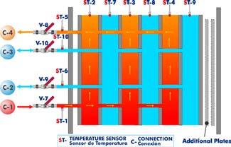


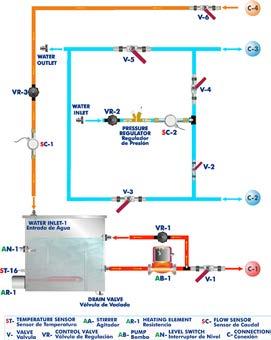
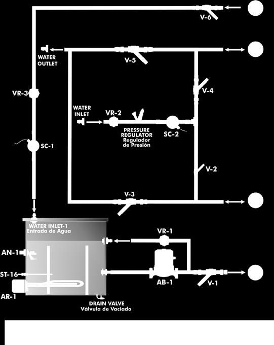
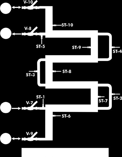
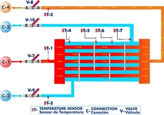
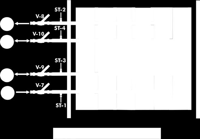

2 PROCESS DIAGRAM AND UNIT ELEMENTS ALLOCATION 5 actuators and 16 sensors controlled from any computer, and working simultaneously 2
: Heat Exchangers type TI 1 TIUS. Base Service Unit: This unit is common for Heat Exchangers type TI and can work with one or several exchangers.")

 to measure the water temperature. Level switch to control the water level in the tank. Stainless steel cover to avoid the contact with hot water.")
3 COMPLETE TECHNICAL SPECIFICATIONS (for main items) With this unit there are several options and possibilities: - Main items: 1, 2, 3, 4, 5 and 6. - Optional items: 7, 8, 9, 10 and 11. Let us describe first the main items (1 to 6): Heat Exchangers type TI 1 TIUS. Base Service Unit: This unit is common for Heat Exchangers type TI and can work with one or several exchangers. This unit performs the following tasks: Heating the water. Pumping of hot water. Change in the direction of cold water flows. Cold and hot water measures. Anodized aluminum frame and panels made of painted steel. Main metallic elements made of stainless steel. Diagram in the front panel with distribution of the elements similar to the real one. Stainless steel tank (30 l), equipped with: Electric heating element (3000 W) with thermostat (70 ºC), to heat the water, computer controlled. PID temperature control. Temperature sensor ( J type) to measure the water temperature. Level switch to control the water level in the tank. Stainless steel cover to avoid the contact with hot water. In this cover there is a hole that allows us to visualize the water level and also to stuff the tank. Draining water valve. Centrifugal pump with speed control from computer, range: 0 3 l/min. Two flow sensors, one for hot water and the other for cold water, range: l/min. Control valves for the cold and hot water. Four ball valves that, depending on how we manipulate them, give us co-current or counter-current flux in the exchanger. Two ball valves to control and drain the hot water of the base unit. Pressure regulator to avoid the introduction of too much pressure in the exchangers, tared at 0.6 Bar. Four flexible tubes to connect with the different exchangers. TICC/CIB. Control Interface Box: This control interface is common for Heat Exchangers type TI and can work with one or several exchangers. Control interface box with process diagram in the front panel and with the same distribution that the different elements located in the unit, for an easy understanding by the student. All sensors, with their respective signals, are properly manipulated from -10V. to +10V. computer output. Sensors connectors in the interface have different pines numbers (from 2 to 16), to avoid connection errors. Single cable between the control interface box and computer. The unit control elements are permanently computer controlled, without necessity of changes or connections during the whole process test procedure. Simultaneous visualization in the computer of all parameters involved in the process. Calibration of all sensors involved in the process. Real time curves representation about system responses. Storage of all the process data and results in a file. Graphic representation, in real time, of all the process/system responses. All the actuators values can be changed at any time from the keyboard allowing the analysis about curves and responses of the whole process. All the actuators and sensors values and their responses are displayed on only one screen in the computer. Shield and filtered signals to avoid external interferences. Real time PID control with flexibility of modifications from the computer keyboard of the PID parameters, at any moment during the process. Real time PID and on/off control for pumps, compressors, heating elements, control valves, etc. Real time PID control for parameters involved in the process simultaneously. Proportional control, integral control and derivative control, based on the real PID mathematical formula, by changing the values, at any time, of the three control constants (proportional, integral and derivative constants). Open control allowing modifications, at any moment and in real time, of parameters involved in the process simultaneously. Possibility of automatization of the actuators involved in the process. Three safety levels, one mechanical in the unit, another electronic in the control interface and the third one in the control software. 3 DAB. Data Acquisition Board: Common for the modules type TXC. PCI Express Data acquisition board (National Instruments) to be placed in a computer slot. Bus PCI Express. Analog input: Number of channels= 16 single-ended or 8 differential. Resolution=16 bits, 1 in Sampling rate up to: 250 KS/s (kilo samples per second). Input range (V)=±10 V. Data transfers=dma, interrupts, programmed I/0. DMA channels=6. Analog output: Number of channels=2. Resolution=16 bits, 1 in Maximum output rate up to: 900 KS/s. Output range (V)=±10 V. Data transfers=dma, interrupts, programmed I/0. Digital Input/Output: Number of channels=24 inputs/outputs. D0 or DI Sample Clock frequency: 0 to 100 MHz. Timing: Number of Counter/timers=4. Resolution: Counter/timers: 32 bits. 3 TIUS TICC/CIB DAB


4 Complete Technical Specifications (for main items) 4 Heat Exchangers available to be used with the Base Service Unit: 4.1 TITC. Concentric Tube Heat Exchanger: This Concentric Tube Heat Exchanger allows the study of heat transfer between hot water flowing through an internal tube and cold water flowing in the ring area lying between the internal and the external tubes. This exchanger allows measuring hot and cold water temperatures at different points of the exchanger. Anodized aluminum frame and panels made of painted steel. Main metallic elements made of stainless steel. Diagram in the front panel with distribution of the elements similar to the real one. The exchanger is formed by two concentric copper tubes with hot water circulating through the interior tube and cold water circulating in the ring space. This exchanger has two equal sections of 500 mm each one, where heat transfer takes place. Exchange length: L = 2 x 0.5 = 1 m. Internal tube: Internal diameter: D int = ³ m. External diameter: Dext = ³ m. Thickness = 10 m - ³. Heat transfer internal area: A h = m². Heat transfer external area: A c = m². External tube: Internal diameter: D int = ³ m. External diameter: D ext = ³ m. TITC Thickness = 10 - ³ m. Six temperature sensors ( J type): Three temperature sensors for measuring cold water temperature: Cold water inlet. Cold water mid-position. Cold water outlet. Three temperature sensors for measuring hot water temperature: Hot water inlet. Hot water mid-position. Hot water outlet. Easy connection to the Base Service Unit. This unit is supplied with 8 manuals: Required Services, Assembly and Installation, Interface and Control Software, Starting-up, Safety, Maintenance, Calibration & Practices Manuals. Computer Control Software: PID Computer Control + Data Acquisition + Data Management Software for Concentric Tube Heat Exchanger (TITC). The three softwares are part of the SCADA system. Compatible with actual Windows operating systems. Graphic and intuitive simulation of the process in screen. Compatible with the industry standards. Registration and visualization of all process variables in an automatic and simultaneous way. Flexible, open and multicontrol software, developed with actual windows graphic systems, acting simultaneously on all process parameters. Analog and digital PID control. PID menu and set point selection required in the whole work range. Management, processing, comparison and storage of data. Sampling velocity up to 250 KS/s (kilo samples per second). Calibration system for the sensors involved in the process. It allows the registration of the alarms state and the graphic representation in real time. Comparative analysis of the obtained data, after the process and modification of the conditions during the process. Open software, allowing the teacher to modify texts, instructions. Teacher s and student s passwords to facilitate the teacher s control on the student, and allowing the access to different work levels. This unit allows the 30 students of the classroom to visualize simultaneously all the results and the manipulation of the unit, during the process, by using a projector or an electronic whiteboard. 4

5 Complete Technical Specifications (for main items) 4 Heat Exchangers available to be used with the Base Service Unit: 4.2 TITCA. Extended Concentric Tube Heat Exchanger: This Extended Concentric Tube Heat Exchanger allows the study of heat transfer between hot water flowing through an internal tube and cold water flowing in the ring area lying between the internal and the external tubes. This exchanger allows measuring hot and cold water temperatures at different points of the exchanger. TITCA is a more sophisticated unit than TITC, with four longer tube sections, giving four times the overall heat transfer area and three interim temperature measurement points (temperature sensors) in each fluid stream. This exchanger has sufficient heat transfer area for demonstrating the typical counter-current flow conditions where the outlet of the heated stream is hotter than the outlet of the cooled stream. Anodized aluminum frame and panels made of painted steel. Main metallic elements made of stainless steel. Diagram in the front panel with distribution of the elements similar to the real one. The exchanger is formed by two concentric copper tubes with hot water circulating through the interior tube and cold water circulating in the ring space. This exchanger has four equal sections of 1000 mm each one, where heat transfer takes place. Exchange length: L=4x1=4 m. Internal tube: Internal diameter: D int = m. External diameter: D ext = m. Thickness = 10-3 m. Heat transfer internal area: A h = m². Heat transfer external area: A c = m². External tube: Internal diameter: D int = m. External diameter: D ext = m. Thickness = 10-3 m. Ten temperature sensors ( J type): Five temperature sensors for measuring cold water temperature: Cold water inlet. Cold water at different interim positions (3). Cold water outlet. Five temperature sensors for measuring hot water temperature: Hot water inlet. Hot water at different interim positions (3). Hot water outlet. Easy connection to the Base Service Unit. This unit is supplied with 8 manuals: Required Services, Assembly and Installation, Interface and Control Software, Starting-up, Safety, Maintenance, Calibration & Practices Manuals. Computer Control Software: PID Computer Control + Data Acquisition + Data Management Software for Extended Concentric Tube Heat Exchanger (TITCA). The three softwares are part of the SCADA system. Compatible with actual Windows operating systems. Graphic and intuitive simulation of the process in screen. Compatible with the industry standards. Registration and visualization of all process variables in an automatic and simultaneous way. Flexible, open and multicontrol software, developed with actual windows graphic systems, acting simultaneously on all process parameters. Analog and digital PID control. PID menu and set point selection required in the whole work range. Management, processing, comparison and storage of data. Sampling velocity up to 250 KS/s (kilo samples per second). Calibration system for the sensors involved in the process. It allows the registration of the alarms state and the graphic representation in real time. Comparative analysis of the obtained data, after the process and modification of the conditions during the process. Open software, allowing the teacher to modify texts, instructions. Teacher s and student s passwords to facilitate the teacher s control on the student, and allowing the access to different work levels. This unit allows the 30 students of the classroom to visualize simultaneously all the results and the manipulation of the unit, during the process, by using a projector or an electronic whiteboard. TITCA 5


6 Complete Technical Specifications (for main items) 4 Heat Exchangers available to be used with the Base Service Unit: 4.3 TIPL. Plate Heat Exchanger: This Plate Heat Exchanger allows the study of heat transfer between hot and cold water through alternate channels formed between parallel plates. The exchanger allows measuring cold and hot temperatures at the inlet and outlet of the exchanger. Anodized aluminum frame and panels made of painted steel. Main metallic elements made of stainless steel. Diagram in the front panel with distribution of the elements similar to the real one. Formed by corrugated stainless steel plates. It can be dismantled to observe its structure. Four ports or connections of hot and cold water input and output. Maximum flow: 12m³/h. Maximum work pressure: 10 bar. Maximum work temperature: 100 C. Minimum work temperature: 0 C. Maximum number of plates: 20. Internal circuit capacity: l. External circuit capacity: 0.22 l. Area: 0.32 m². Four temperature sensors ( J type): Two temperature sensors for measuring cold water temperature (inlet and outlet). Two temperature sensors for measuring hot water temperature (inlet and outlet). Easy connection to the Base Service Unit. This unit is supplied with 8 manuals: Required Services, Assembly and Installation, Interface and Control Software, Starting-up, Safety, Maintenance, Calibration & Practices Manuals. Computer Control Software: PID Computer Control+Data Acquisition+Data Management Software for Plate Heat Exchanger (TIPL). The three softwares are part of the SCADA system. Compatible with actual Windows operating systems. Graphic and intuitive simulation of the process in screen. Compatible with the industry standards. Registration and visualization of all process variables in an automatic and simultaneous way. Flexible, open and multicontrol software, developed with actual windows graphic systems, acting simultaneously on all process parameters. Analog and digital PID control. PID menu and set point selection required in the whole work range. Management, processing, comparison and storage of data. Sampling velocity up to 250 KS/s (kilo samples per second). Calibration system for the sensors involved in the process. It allows the registration of the alarms state and the graphic representation in real time. Comparative analysis of the obtained data, after the process and modification of the conditions during the process. Open software, allowing the teacher to modify texts, instructions. Teacher s and student s passwords to facilitate the teacher s control on the student, and allowing the access to different work levels. This unit allows the 30 students of the classroom to visualize simultaneously all the results and the manipulation of the unit, during the process, by using a projector or an electronic whiteboard. TIPL 6

7 Complete Technical Specifications (for main items) 4 Heat Exchangers available to be used with the Base Service Unit: 4.4 TIPLA. Extended Plate Heat Exchanger: This Extended Plate Heat Exchanger allows the study of heat transfer between hot and cold water through alternate channels formed between parallel plates. The exchanger allows measuring cold and hot temperatures at different points of the exchanger. Anodized aluminum frame and panels made of painted steel. Main metallic elements made of stainless steel. Diagram in the front panel with distribution of the elements similar to the real one. Formed by corrugated stainless steel plates. It can be dismantled to observe its structure. Four ports or connections of hot and cold water input and output. Maximum flow: 12 m³/h. Maximum work pressure: 10 bar. Maximum work temperature: 100 C. Minimum work temperature: 0 C. Maximum number of plates: 20. Internal circuit capacity: l. External circuit capacity: 0.22 l. Area: 0.32 m². Ten temperature sensors ( J type): Five temperature sensors for measuring cold water temperature (inlet, outlet and interim positions). Five temperature sensors for measuring hot water temperature (inlet, outlet and interim positions). Easy connection to the Base Service Unit. This unit is supplied with 8 manuals: Required Services, Assembly and Installation, Interface and Control Software, Starting-up, Safety, Maintenance, Calibration & Practices Manuals. Computer Control Software: PID Computer Control+Data Acquisition+Data Management Software for Extended Plate Heat Exchanger (TIPLA). The three softwares are part of the SCADA system. Compatible with actual Windows operating systems. Graphic and intuitive simulation of the process in screen. Compatible with the industry standards. Registration and visualization of all process variables in an automatic and simultaneous way. Flexible, open and multicontrol software, developed with actual windows graphic systems, acting simultaneously on all process parameters. Analog and digital PID control. PID menu and set point selection required in the whole work range. Management, processing, comparison and storage of data. Sampling velocity up to 250 KS/s (kilo samples per second). Calibration system for the sensors involved in the process. It allows the registration of the alarms state and the graphic representation in real time. Comparative analysis of the obtained data, after the process and modification of the conditions during the process. Open software, allowing the teacher to modify texts, instructions. Teacher s and student s passwords to facilitate the teacher s control on the student, and allowing the access to different work levels. This unit allows the 30 students of the classroom to visualize simultaneously all the results and the manipulation of the unit, during the process, by using a projector or an electronic whiteboard. TIPLA 7

8 Complete Technical Specifications (for main items) 4 Heat Exchangers available to be used with the Base Service Unit: 4.5 TICT. Shell & Tube Heat Exchanger: It consists on a group of tubes inside the heat exchanger. The hot water flows through the internal tubes and the cooling water circulates through the space between the internal tubes and the shell. There are traverse baffles placed in the shell to guide the cold water to maximize the heat transfer. Anodized aluminum frame and panels made of painted steel. Main metallic elements made of stainless steel. Diagram in the front panel with distribution of the elements similar to the real one. Formed by tubes of stainless steel with hot water circulating in the interior. Four segmented baffles located transversaly in the shell. Exchange length of the shell and each tube: L = 0.5 m. Internal tube (21 tubes): Internal diameter: D int = ³ m. External diameter: D ext = m. Thickness = 10-3 m. TICT Internal heat transfer area: A h = m². External heat transfer area : A c = m². Shell: Internal diameter: D int,c = m. External diameter: D ext,c = m. Thickness = m. Seven temperature sensors ( J type), for measuring cold and hot water temperatures at different points of the exchanger. Easy connection to the Base Service Unit. This unit is supplied with 8 manuals: Required Services, Assembly and Installation, Interface and Control Software, Starting-up, Safety, Maintenance, Calibration & Practices Manuals. Computer Control Software: PID Computer Control+Data Acquisition+Data Management Software for Shell & Tube Heat Exchanger (TICT). The three softwares are part of the SCADA system. Compatible with actual Windows operating systems. Graphic and intuitive simulation of the process in screen. Compatible with the industry standards. Registration and visualization of all process variables in an automatic and simultaneous way. Flexible, open and multicontrol software, developed with actual windows graphic systems, acting simultaneously on all process parameters. Analog and digital PID control. PID menu and set point selection required in the whole work range. Management, processing, comparison and storage of data. Sampling velocity up to 250 KS/s (kilo samples per second). Calibration system for the sensors involved in the process. It allows the registration of the alarms state and the graphic representation in real time. Comparative analysis of the obtained data, after the process and modification of the conditions during the process. Open software, allowing the teacher to modify texts, instructions. Teacher s and student s passwords to facilitate the teacher s control on the student, and allowing the access to different work levels. This unit allows the 30 students of the classroom to visualize simultaneously all the results and the manipulation of the unit, during the process, by using a projector or an electronic whiteboard. 8

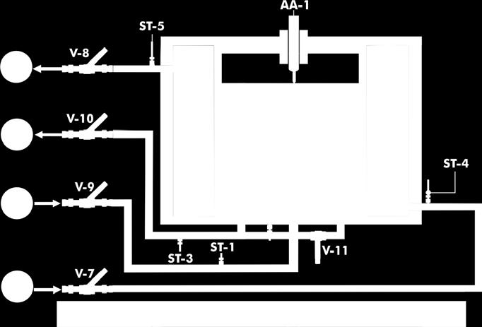
9 Complete Technical Specifications (for main items) 4 Heat Exchangers available to be used with the Base Service Unit: 4.6 TIVE. Jacketed Vessel Heat Exchanger: This Jacketed Vessel Heat Exchanger allows the study of heat transfer between hot water flowing through a jacket and the cold water contained in a vessel. It can work in continuous supply or in a batch process (heating of a constant mass of water contained in a vessel). The exchanger allows measuring temperatures at the inlet and outlet of the exchanger in cold as well as in hot water. Anodized aluminum frame and panels made of painted steel. Main metallic elements made of stainless steel. Diagram in the front panel with distribution of the elements similar to the real one. Constituted of a vessel. Vessel total volume: 14 l. Interior vessel volume: 7 l approx. Jacket volume: 7 l approx. Overflow or a pipe allows the exit of the water in the vessel through its upper part to maintain a constant flow during the process with a continuous supply. TIVE Jacket surrounds the vessel through where hot water flows. Electric stirrer. Five temperature sensors ( J type): Three temperature sensors for measuring cold water temperature. Two temperature sensors for measuring hot water temperature. Easy connection to the Base Service Unit. This unit is supplied with 8 manuals: Required Services, Assembly and Installation, Interface and Control Software, Starting-up, Safety, Maintenance, Calibration & Practices Manuals. Computer Control Software: PID Computer Control+Data Acquisition+Data Management Software for Jacketed Vessel Heat Exchanger (TIVE). The three softwares are part of the SCADA system. Compatible with actual Windows operating systems. Graphic and intuitive simulation of the process in screen. Compatible with the industry standards. Registration and visualization of all process variables in an automatic and simultaneous way. Flexible, open and multicontrol software, developed with actual windows graphic systems, acting simultaneously on all process parameters. Analog and digital PID control. PID menu and set point selection required in the whole work range. Management, processing, comparison and storage of data. Sampling velocity up to 250 KS/s (kilo samples per second). Calibration system for the sensors involved in the process. It allows the registration of the alarms state and the graphic representation in real time. Comparative analysis of the obtained data, after the process and modification of the conditions during the process. Open software, allowing the teacher to modify texts, instructions. Teacher s and student s passwords to facilitate the teacher s control on the student, and allowing the access to different work levels. This unit allows the 30 students of the classroom to visualize simultaneously all the results and the manipulation of the unit, during the process, by using a projector or an electronic whiteboard. 9


10 Complete Technical Specifications (for main items) 4 Heat Exchangers available to be used with the Base Service Unit: 4.7 TIVS. Coil Vessel Heat Exchanger: This heat exchanger allows the study of heat transfer between hot water flowing through a coil and cold water contained in the vessel. It can work in continuous supply or in a batch process. Anodized aluminum frame and panels made of painted steel. Main metallic elements made of stainless steel. Diagram in the front panel with distribution of the elements similar to the real one. Formed by a pvc-glass vessel, volume: 14 l. Overflow or pvc-glass tube lets the output of water from the vessel in the upper part in order to maintain the flow constant for continue supply process. Copper coil where the water circulates: D int = 4.35 mm. D ext = 6.35 mm. Total length of the tube that forms the coil: 1.5 m. Electric stirrer. Five temperature sensors ( J type): Three temperature sensors for measuring cold water temperature. Two temperature sensors for measuring hot water temperature. Easy connection to the Base Service Unit. This unit is supplied with 8 manuals: Required Services, Assembly and Installation, Interface and Control Software, Starting-up, Safety, Maintenance, Calibration & Practices Manuals. Computer Control Software: PID Computer Control+Data Acquisition+Data Management Software for Coil Vessel Heat Exchanger (TIVS). The three softwares are part of the SCADA system. Compatible with actual Windows operating systems. Graphic and intuitive simulation of the process in screen. Compatible with the industry standards. Registration and visualization of all process variables in an automatic and simultaneous way. Flexible, open and multicontrol software, developed with actual windows graphic systems, acting simultaneously on all process parameters. Analog and digital PID control. PID menu and set point selection required in the whole work range. Management, processing, comparison and storage of data. Sampling velocity up to 250 KS/s (kilo samples per second). Calibration system for the sensors involved in the process. It allows the registration of the alarms state and the graphic representation in real time. Comparative analysis of the obtained data, after the process and modification of the conditions during the process. Open software, allowing the teacher to modify texts, instructions. Teacher s and student s passwords to facilitate the teacher s control on the student, and allowing the access to different work levels. This unit allows the 30 students of the classroom to visualize simultaneously all the results and the manipulation of the unit, during the process, by using a projector or an electronic whiteboard. TIVS 10

11 Complete Technical Specifications (for main items) 4 Heat Exchangers available to be used with the Base Service Unit: 4.8 TIFT. Turbulent Flow Heat Exchanger: This Turbulent Flow Heat Exchanger let us study the heat transfer between hot water that circulates through an internal tube and cold water that flows through the annular zone between the internal and the external tube. This exchanger let us measure cold water and hot water temperatures at different points of the exchanger. Anodized aluminum frame and panels made of painted steel. Main metallic elements made of stainless steel. Diagram in the front panel with distribution of the elements similar to the real one. Formed by two copper concentric tubes with hot water circulating through the internal tube and cold water circulating through the annular space. The exchanger has 4 equal sections of 500 mm each one, where the heat transfer takes place. Exchange length: L = 4 x 0.5 = 2 m. TIFT Internal tube: Internal diameter: D int = m. External diameter: D ext = m. Thickness = 10-3 m. Internal heat transfer area: A h = m². External heat transfer area: A c = m². External tube: Internal diameter: D int,c = m. External diameter: D ext,c = m. Thickness = 10-3 m. Twelve temperature sensors: ( J type): Cold water temperature sensor at the exchanger inlet or outlet. Hot water sensor at the exchanger inlet. Cold water sensor between the first and second stretch of the exchanger. Hot water sensor between the first and second stretch of the exchanger. Cold water sensor between the second and third stretch of the exchanger. Hot water sensor between the second and third stretch of the exchanger. Cold water sensor between the third and fourth stretch of the exchanger. Hot water sensor between the third and fourth stretch of the exchanger. Cold water temperature sensor at the exchanger inlet or outlet. Hot water sensor at the exchanger outlet. Temperature sensor of the exterior surface of the interior tube at the exchanger inlet. Temperature sensor of the exterior surface of the interior tube at the exchanger outlet. Easy connection to the Base Service Unit. This unit is supplied with 8 manuals: Required Services, Assembly and Installation, Interface and Control Software, Starting-up, Safety, Maintenance, Calibration & Practices Manuals. Computer Control Software: PID Computer Control+Data Acquisition+Data Management Software for Turbulent Flow Heat Exchanger (TIFT). The three softwares are part of the SCADA system. Compatible with actual Windows operating systems. Graphic and intuitive simulation of the process in screen. Compatible with the industry standards. Registration and visualization of all process variables in an automatic and simultaneous way. Flexible, open and multicontrol software, developed with actual windows graphic systems, acting simultaneously on all process parameters. Analog and digital PID control. PID menu and set point selection required in the whole work range. Management, processing, comparison and storage of data. Sampling velocity up to 250 KS/s (kilo samples per second). Calibration system for the sensors involved in the process. It allows the registration of the alarms state and the graphic representation in real time. Comparative analysis of the obtained data, after the process and modification of the conditions during the process. Open software, allowing the teacher to modify texts, instructions. Teacher s and student s passwords to facilitate the teacher s control on the student, and allowing the access to different work levels. This unit allows the 30 students of the classroom to visualize simultaneously all the results and the manipulation of the unit, during the process, by using a projector or an electronic whiteboard. 11

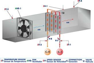
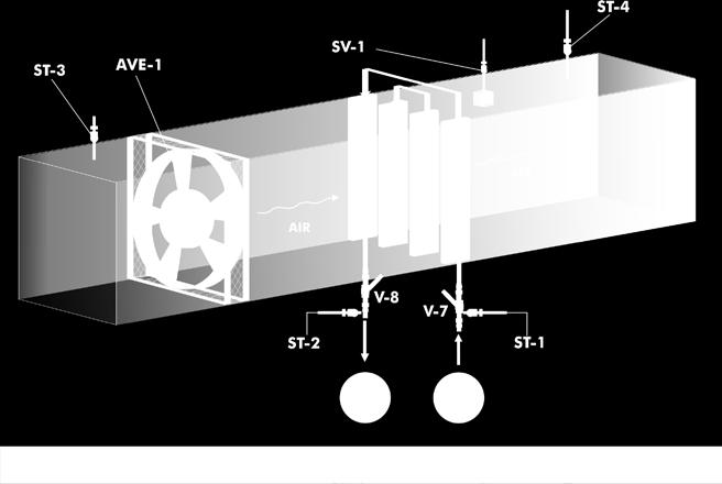
12 Complete Technical Specifications (for main items) 4 Heat Exchangers available to be used with the Base Service Unit: 4.9 TICF. Cross Flow Heat Exchanger: The cross flow heat exchanger is designed to study heat transfer between two fluids in cross flow configuration. Hot water flow coming from the base unit enters and leaves a radiator perpendicular to an air current, which is generated by a fan. The heat exchanger allows to measure water and air temperatures at the inlet and outlet of the exchanger. Anodized aluminum frame and panels made of painted steel. Main metallic elements made of stainless steel. Diagram in the front panel with distribution of the elements similar to the real one. Poly methyl methacrylate (PMMA) rectangular duct of 800 x 200 x 200 mm. Radiator located across the air duct. The fins of the radiator are made of aluminum and have a heat transfer area of mm². Axial fan with speed control from computer (PC). It provides a maximum air velocity of 3 m/s. Four J type temperature sensors to measure input and output water and air temperatures. Velocity sensor to measure air velocity, range: 0 4 m/s. Two ball valves. Easy connection to the Base Unit. This unit is supplied with 8 manuals: Required Services, Assembly and Installation, Interface and Control Software, Starting-up, Safety, Maintenance, Calibration & Practices Manuals. Computer Control Software: PID Computer Control+Data Acquisition+Data Management Software for Cross Flow Heat Exchanger (TICF). The three softwares are part of the SCADA system. Compatible with actual Windows operating systems. Graphic and intuitive simulation of the process in screen. Compatible with the industry standards. Registration and visualization of all process variables in an automatic and simultaneous way. Flexible, open and multicontrol software, developed with actual windows graphic systems, acting simultaneously on all process parameters. Analog and digital PID control. PID menu and set point selection required in the whole work range. Management, processing, comparison and storage of data. Sampling velocity up to 250 KS/s (kilo samples per second). Calibration system for the sensors involved in the process. It allows the registration of the alarms state and the graphic representation in real time. Comparative analysis of the obtained data, after the process and modification of the conditions during the process. Open software, allowing the teacher to modify texts, instructions. Teacher s and student s passwords to facilitate the teacher s control on the student, and allowing the access to different work levels. This unit allows the 30 students of the classroom to visualize simultaneously all the results and the manipulation of the unit, during the process, by using a projector or an electronic whiteboard. TICF 5 Cables and Accessories, for normal operation. 6 Manuals: This unit is supplied with 8 manuals: Required Services, Assembly and Installation, Interface and Control Software, Starting-up, Safety, Maintenance, Calibration & Practices Manuals. 12
13 EXERCISES AND PRACTICAL POSSIBILITIES TO BE DONE WITH THE MAIN ITEMS Practices to be done with the Concentric Tube Heat Exchanger (TITC): 1.- Global energy balance in the heat exchanger and the study of losses. 2.- Exchanger effectiveness determination. NTU Method. 3.- Study of the heat transfer under counter-current and co-current flow conditions. 4.- Flow influence on the heat transfer. Reynolds number calculation. Additional practical possibilities: 5.- Control system: Temperature sensors calibration. 6.- Control system: Flow sensors calibration. 7.- Study of the hysteresis of the flow sensor. Practices to be done with the Extended Concentric Tube Heat Exchanger (TITCA): 8.- Global energy balance in the heat exchanger and the study of losses. 9.- Exchanger effectiveness determination. NTU Method Study of the heat transfer under counter-current and co-current flow conditions Flow influence on the heat transfer. Reynolds number calculation. Additional practical possibilities: 12.- Control system: Temperature sensors calibration Control system: Flow sensors calibration Study of the hysteresis of the flow sensor. Practices to be done with the Plate Heat Exchanger (TIPL): 15.- Global energy balance in the heat exchanger and the study of losses Exchanger effectiveness determination. NTU Method Study of the heat transfer under counter-current and co-current flow conditions Flow influence on the heat transfer. Reynolds number calculation. Additional practical possibilities: 19.- Control system: Temperature sensors calibration Control system: Flow sensors calibration Study of the hysteresis of the flow sensor. Practices to be done with the Extended Plate Heat Exchanger (TIPLA): 22.- Global energy balance in the heat exchanger and the study of losses Exchanger effectiveness determination. NTU Method Study of the heat transfer under counter-current and co-current flow conditions Flow influence on the heat transfer. Reynolds number calculation. Additional practical possibilities: 26.- Control system: Temperature sensors calibration Control system: Flow sensors calibration tudy of the hysteresis of the flow sensor. Practices to be done with the Shell & Tube Heat Exchanger (TICT): 29.- Global energy balance in the heat exchanger and the study of losses Exchanger effectiveness determination. NTU Method Study of the heat transfer under counter-current and co-current flow conditions Flow influence on the heat transfer. Reynolds number calculation. Additional practical possibilities: 33.- Control system: Temperature sensors calibration Control system: Flow sensors calibration tudy of the hysteresis of the flow sensor. Practices to be done with the Jacketed Vessel Heat Exchanger (TIVE): 36.- Global balance of energy in the heat exchanger and losses study Determination of the exchanger effectiveness. NTU Method Influence of the flow on the heat transfer. Calculation of the number of Reynolds Influence of the vessel stirring on the heat transfer when operating in batches Influence of the vessel s water volume on the heat transfer when operating in batches. Additional practical possibilities: 41.- Control system: Temperature sensors calibration Control system: Flow sensors calibration Study of the hysteresis of the flow sensor. Practices to be done with the Coil Vessel Heat Exchanger (TIVS): 44.- Global balance of energy in the heat exchanger and the study of losses Determination of the exchanger effectiveness. NTU Method Influence of the flow on the heating transfer. Calculation of Reynolds number Influence of the stirring vessel on the heat transfer with operation in batches Influence of the water volume in the vessel on the heat transfer with operation in batches. Additional practical possibilities: 49.- Control System: Temperature sensors calibration Control System: Flow sensors calibration Study of the hysteresis of the flow sensor. Practices to be done with the Turbulent Flow Heat Exchanger (TIFT): 52.- Global energy balance in the heat exchanger and loss study Determination of the exchanger effectiveness. NTU Method Study of the heat transfer in counter-current and co-current flow conditions Flow influence on heat transfer. Reynolds number calculation Obtaining of the correlation that relates Nusselt number with Reynolds number and Prandtl number Obtaining of the heat transfer coefficients by convection. Additional practical possibilities: 58.-Control system: Temperature sensors calibration Control system: Flow sensors calibration Study of the hysteresis in the flow sensors. Practices to be done with the Cross Flow Heat Exchanger (TICF): 61.- Introduction to the concept of psychometric properties Effect of temperature differential on the heat transfer coefficient Familiarization with cross flow heat exchanger Overall energy balance in the heat exchanger and study of losses Determination of the exchanger effectiveness (NTU method) Influence of air and water flow on the heat transfer. Reynolds number calculation. Additional practical possibilities: 67.- Control system: Temperature sensors calibration Control system: Flow sensors calibration Study of the hysteresis in the flow sensors. Other possibilities to be done with this System: 70.- Many students view results simultaneously. To view all results in real time in the classroom by means of a projector or an electronic whiteboard Open Control, Multicontrol and Real Time Control. This unit allows intrinsically and/or extrinsically to change the span, gains; proportional, integral, derivate parameters; etc, in real time The Computer Control System with SCADA and PID Control allow a real industrial simulation This unit is totally safe as uses mechanical, electrical and electronic, and software safety devices This unit can be used for doing applied research This unit can be used for giving training courses to Industries even to other Technical Education Institutions Control of the unit process through the control interface box without the computer Visualization of all the sensors values used in the unit process. - By using PLC-PI additional 19 more exercises can be done. - Several other exercises can be done and designed by the user. 13
14 REQUIRED SERVICES - Electrical supply: single-phase, 220 V/50 Hz or 110 V/60 Hz. - Water supply (0 to 6 l/min approx) and drain. - Computer. DIMENSIONS AND WEIGHTS TICC: TIUS. Base Service Unit: -Dimensions: 1100 x 630 x 500 mm approx. (43.30 x x inches approx.) -Weight: 50 Kg approx. (110.2 pounds approx.) TITC. Unit: -Dimensions: 1100 x 630 x 320 mm approx. (43.30 x x inches approx.) -Weight: 20 Kg approx. (44.09 pounds approx.) TITCA. Unit: -Dimensions: 1500 x 700 x 320 mm approx. (59.05 x x inches approx.) -Weight: 30 Kg approx. (66.13 pounds approx.) TIPL. Unit: -Dimensions: 1100 x 630 x 320 mm approx. (43.30 x x inches approx.) -Weight: 20 Kg approx. (44.09 pounds approx.) TIPLA. Unit: -Dimensions: 1200 x 700 x 320 mm approx. (47.24 x x inches approx.) -Weight: 25 Kg approx. (55.11 pounds approx.) TICT. Unit: -Dimensions: 1100 x 630 x 400 mm approx. (43.30 x x inches approx.) -Weight: 30 Kg approx. (66.13 pounds approx.) TIVE. Unit: -Dimensions: 1100 x 630 x 700 mm approx. (43.30 x x inches approx.) -Weight: 35 Kg approx. (77.16 pounds approx.) TIVS. Unit: -Dimensions: 1100 x 630 x 700 mm approx. (43.30 x x inches approx.) -Weight: 30 Kg approx. (66.13 pounds approx.) TIFT. Unit: -Dimensions: 1100 x 630 x 350 mm approx. (43.30 x x inches approx.) -Weight: 20 Kg approx. (44.09 pounds approx.) TICF. Unit: -Dimensions: 1100 x 630 x 600 mm approx. (43.30 x x inches approx.) -Weight: 20 Kg approx. (44.09 pounds approx.) Control Interface Box: -Dimensions: 490 x 330 x 310 mm approx. (19.29 x x inches approx.) -Weight: 10 Kg approx. (22 pounds approx.) AVAILABLE VERSIONS Offered in this catalogue: - TICC. Computer Controlled Heat Exchangers Training System. Offered in other catalogue: - TICB. Heat Exchangers Training System. 14
15 Working options: Counter-current (CC) and Co-current (PL). Sensors: SOFTWARE MAIN SCREENS SCADA and PID Control Main screens Concentric Tube Heat Exchanger (TITC) Main Screens Note: Sensors: ST=Temperature sensor. SC=Flow sensor. Actuators: AB=Pump. AR=Heating element. AN= Level switch. Calculations: 15
 Main Screens (continuation)")
16 Software Main Screens Concentric Tube Heat Exchanger (TITC) Main Screens (continuation) Constants: 16
 Main Screens Note: Sensors: ST=Temperature sensor. SC=Flow sensor.")
17 Software Main Screens Working options: Counter-current (CC) and Co-current (PL). Sensors: Extended Concentric Tube Heat Exchanger (TITCA) Main Screens Note: Sensors: ST=Temperature sensor. SC=Flow sensor. Actuators: AB=Pump. AR=Heating element. AN= Level switch. Calculations: 17
18 Software Main Screens Constants: Extended Concentric Tube Heat Exchanger (TITCA) Main Screens (continuation) 18
19 Software Main Screens Plate Heat Exchanger (TIPL) Main Screens Working options: Counter-current (CC) and Co-current (PL) Sensors: Note: Sensors: ST=Temperature sensor. SC=Flow sensor. Actuators: AB=Pump. AR=Heating element. AN= Level switch. Calculations: 19
20 Software Main Screens Constants: Plate Heat Exchanger (TIPL) Main Screens (continuation) 20

21 Software Main Screens Extended Plate Heat Exchanger (TIPLA) Main Screens Working options: Counter-current (CC) and Co-current (PL). Sensors: Note: Sensors: ST=Temperature sensor. SC=Flow sensor. Actuators: AB=Pump. AR=Heating element. AN= Level switch Calculations: 21
 Main Screens (continuation)")
22 Software Main Screens Constants: Extended Plate Heat Exchanger (TIPLA) Main Screens (continuation) 22
23 Software Main Screens Shell & Tube Heat Exchanger (TICT) Main Screens Working options: Counter-current (CC) and Co-current (PL). Sensors: Note: Sensors: ST=Temperature sensor. SC=Flow sensor. Actuators: AB=Pump. AR=Heating element. AN= Level switch. Calculations: 23
24 Software Main Screens Constants: Shell & Tube Heat Exchanger (TICT) Main Screens (continuation) 24

25 Software Main Screens Sensors: Jacketed Vessel Heat Exchanger (TIVE) Main Screens Note: Sensors: ST=Temperature sensor. SC=Flow sensor. Actuators: AB=Pump. AR=Heating element. AA=Stirrer. AN= Level switch Calculations: 25
26 Software Main Screens Constants: Jacketed Vessel Heat Exchanger (TIVE) Main Screens (continuation) 26

27 Software Main Screens Sensors: Coil Vessel Heat Exchanger (TIVS) Main Screens Note: Sensors: ST=Temperature sensor. SC=Flow sensor. Actuators: AB=Pump. AR=Heating element. AA=Stirrer. AN= Level switch. Calculations: 27
28 Software Main Screens Constants: Coil Vessel Heat Exchanger (TIVS) Main Screens (continuation) 28
29 Software Main Screens Turbulent Flow Heat Exchanger (TIFT) Main Screens Working options: Counter-current (CC) and Co-current (PL). Sensors: Note: Sensors: ST=Temperature sensor. SC=Flow sensor. Actuators: AB=Pump. AR=Heating element. AN= Level switch. Calculations: 29
 Main Screens (continuation) Constants:")
30 Software Main Screens Calculations: Turbulent Flow Heat Exchanger (TIFT) Main Screens (continuation) Constants: 30

31 Software Main Screens Cross Flow Heat Exchanger (TICF) Main Screens Sensors: Note: Sensors: ST=Temperature sensor. SC=Flow sensor. SV=Velocity sensor. Actuators: AB=Pump. AR=Heating element. AVE=Fan. AN= Level switch. Calculations: 31
 Main Screens")
32 Software Main Screens Constants: Cross Flow Heat Exchanger (TICF) Main Screens (continuation) 32


33 Software Main Screens Software for Sensors Calibration Example of screen The teacher and the students can calibrate the unit with a password provided by EDIBON. The teacher can restore the factory calibration any time. 33
 Industrial configuration. (PLC) b) Technical and Vocational Education configuration. (ICAI and FSS) c) Multipost Expansions options.")

34 COMPLETE TECHNICAL SPECIFICATIONS (for optional items) Additionally to the main items (1 to 6) described, we can offer, as optional, other items from 7 to 11. All these items try to give more possibilities for: a) Industrial configuration. (PLC) b) Technical and Vocational Education configuration. (ICAI and FSS) c) Multipost Expansions options. (MINI ESN and ESN) a) Industrial configuration 7 PLC. Industrial Control using PLC (it includes PLC-PI Module plus PLC-SOF Control Software): -PLC-PI. PLC Module: This unit is common for the modules type TI and can work with one or several modules. Metallic box. Circuit diagram in the module front panel. Front panel: Digital inputs (X) and Digital outputs (Y) block: 16 Digital inputs, activated by switches and 16 LEDs for confirmation (red). 14 Digital outputs (through SCSI connector) with 14 LEDs for message (green). Analog inputs block: 16 Analog inputs (-10 V. to + 10 V.) (through SCSI connector). Analog outputs block: 4 Analog outputs (-10 V. to + 10 V.) (through SCSI connector). Touch screen: High visibility and multiple functions. Display of a highly visible status. Recipe function. Bar graph function. Flow display function. Alarm list. Multi language function. True type fonts. Back panel: Power supply connector. Fuse 2A. RS-232 connector to PC. USB 2.0 connector to PC. Inside: Power supply outputs: 24 Vdc, 12 Vdc, -12 Vdc, 12 Vdc variable. Panasonic PLC: High-speed scan of 0.32 µsec. for a basic instruction. Program capacity of 32 Ksteps, with a sufficient comment area. Power supply input (100 to 240 V AC). DC input: 16 (24 V DC). Relay output: 14. High-speed counter. Multi-point PID control. Digital inputs/outputs and analog inputs/outputs Panasonic modules. Communication RS232 wire to computer (PC). Dimensions: 490 x 330 x 310 mm. approx. (19.29 x x inches approx.). Weight: 30 Kg. approx. (66 pounds approx.). -TICC/PLC-SOF. PLC Control Software: Always included with PLC supply. Each Heat Exchanger has its own Software. Base Service Unit (TIUS) Heat Exchanger/s Control Interface Box Data Acquisition Board Software for: - Computer Control - Data Acquisition - Data Management PLC CONTROL PLC-SOF. Control Software 1.- Control of the particular unit process through the control interface box without the computer. 2.- Visualization of all the sensors values used in the particular unit process. 3.- Calibration of all sensors included in the particular unit process. 4.- Hand on of all the actuators involved in the particular unit process. 5.- Realization of different experiments, in automatic way, without having in front the particular unit. (These experiments can be decided previously). 6.- Simulation of outside actions, in the cases do not exist hardware elements. (Example: test of complementary tanks, complementary industrialenvironment to the process to be studied, etc). 7.- PLC hardware general use. 8.- PLC process application for the particular unit. 9.- PLC structure PLC inputs and outputs configuration PLC configuration possibilities PLC program languages. PLC-PI. PLC Module Practices to be done with PLC-PI: PLC different programming standard languages (ladder diagram (LD), structured text (ST), instructions list (IL), sequential function chart (SFC), function block diagram (FBD)) New configuration and development of new process Hand on an established process To visualize and see the results and to make comparisons with the particular unit process Possibility of creating new process in relation with the particular unit PLC Programming Exercises Own PLC applications in accordance with teacher and student requirements.
 totally integrated with the Student Software (EDIBON Student Labsoft - ESL-SOF).")
. - ECM-SOF. EDIBON Classroom Manager (Instructor Software).")


.")

 Application Main Screen ERS. EDIBON Results & Statistics Program Package - Student Scores Histogram ECAL.")

35 Complete Technical Specifications (for optional items) b) Technical and Vocational Education configuration 8 TICC/ICAI. Interactive Computer Aided Instruction Software System. This complete software package consists of an Instructor Software (EDIBON Classroom Manager - ECM-SOF) totally integrated with the Student Software (EDIBON Student Labsoft - ESL-SOF). Both are interconnected so that the teacher knows at any moment what is the theoretical and practical knowledge of the students. This software is optional and can be used additionally to items (1 to 6). - ECM-SOF. EDIBON Classroom Manager (Instructor Software). ECM-SOF is the application that allows the Instructor to register students, manage and assign tasks for workgroups, create own content to carry out Practical Exercises, choose one of the evaluation methods to check the Student knowledge and monitor the progression related to the planned tasks for individual students, workgroups, units, etc... so the teacher can know in real time the level of understanding of any student in the classroom. Instructor Software Innovative features: User Data Base Management. Administration and assignment of Workgroup, Task and Training sessions. Creation and Integration of Practical Exercises and Multimedia Resources. Custom Design of Evaluation Methods. Creation and assignment of Formulas & Equations. Equation System Solver Engine. Updatable Contents. Report generation, User Progression Monitoring and Statistics. - ESL-SOF. EDIBON Student Labsoft (Student Software). ESL-SOF is the application addressed to the Students that helps them to understand theoretical concepts by means of practical exercises and to prove their knowledge and progression by performing tests and calculations in addition to Multimedia Resources. Default planned tasks and an Open workgroup are provided by EDIBON to allow the students start working from the first session. Reports and statistics are available to know their progression at any time, as well as explanations for every exercise to reinforce the theoretically acquired technical knowledge. ECM-SOF. EDIBON Classroom Manager (Instructor Software) Application Main Screen ERS. EDIBON Results & Statistics Program Package - Student Scores Histogram ECAL. EDIBON Calculations Program Package - Formula Editor Screen ETTE. EDIBON Training Test & Exam Program Package - Main Screen with Numeric Result Question Student Software Innovative features: Student Log-In & Self-Registration. Existing Tasks checking & Monitoring. Default contents & scheduled tasks available to be used from the first session. Practical Exercises accomplishment by following the Manual provided by EDIBON. Evaluation Methods to prove your knowledge and progression. Test self-correction. Calculations computing and plotting. Equation System Solver Engine. User Monitoring Learning & Printable Reports. Multimedia-Supported auxiliary resources. For more information see ICAI catalogue. Click on the following link: /en/files/expansion/icai/catalog ESL-SOF. EDIBON Student LabSoft (Student Software) Application Main Screen ERS. EDIBON Results & Statistics Program Package - Question Explanation EPE. EDIBON Practical Exercise Program Package Main Screen ECAL. EDIBON Calculations Program Package Main Screen 35
 is a Software package that simulates several faults in any EDIBON Computer Controlled Unit. It is useful for Technical and Vocational level.")


 Multipost Expansions options 10 MINI ESN.")

, through the main computer connected to the unit.")

36 Complete Technical Specifications (for optional items) 9 TICC/FSS. Faults Simulation System. Faults Simulation System (FSS) is a Software package that simulates several faults in any EDIBON Computer Controlled Unit. It is useful for Technical and Vocational level. The FAULTS mode consists in causing several faults in the unit normal operation. The student must find them and solve them. There are several kinds of faults that can be grouped in the following sections: Faults affecting the sensors measurement: - An incorrect calibration is applied to them. - Non-linearity. Faults affecting the actuators: - Actuators channels interchange at any time during the program execution. - Response reduction of an actuator. Faults in the controls execution: - Inversion of the performance in ON/OFF controls. - Reduction or increase of the calculated total response. - The action of some controls is annulled. On/off faults: - Several on/off faults can be included. Example of some screens For more information see FSS catalogue. Click on the following link: /en/files/expansion/fss/catalog c) Multipost Expansions options 10 MINI ESN. EDIBON Mini Scada-Net System for being used with EDIBON Teaching Units. MINI ESN. EDIBON Mini Scada-Net System allows up to 30 students to work with a Teaching Unit in any laboratory, simultaneously. It is useful for both, Higher Education and/or Technical and Vocational Education. The MINI ESN system consists of the adaptation of any EDIBON Computer Controlled Unit with SCADA and PID Control integrated in a local network. This system allows to view/control the unit remotely, from any computer integrated in the local net (in the classroom), through the main computer connected to the unit. Then, the number of possible users who can work with the same unit is higher than in an usual way of working (usually only one). Main characteristics: - It allows up to 30 students to work simultaneously with the EDIBON Computer Controlled Unit with SCADA and PID Control, connected in a local net. - Open Control + Multicontrol + Real Time Control + Multi Student Post. - Instructor controls and explains to all students at the same time. - Any user/student can work doing "real time" control/multicontrol and visualisation. - Instructor can see in the computer what any user/student is doing in the unit. - Continuous communication between the instructor and all the users/students connected. Main advantages: - It allows an easier and quicker understanding. - This system allows you can save time and cost. - Future expansions with more EDIBON Units. For more information see MINI ESN catalogue. Click on the following link: /en/files/expansion/mini-esn/catalog 9 available Heat Exchangers Control Interface Box MINI ESN. EDIBON Mini Scada-Net System Base Service Unit (TIUS) Instructors' Central Computer LOCAL NET FOR 30 STUDENTS 1 UNIT= up to 30 STUDENTS can work simultaneously Software for: - Computer Control - Data Acquisition - Data Management Mini Scada-Net Software Note: The MINI ESN system can be used with any EDIBON computer controlled unit 11 ESN. EDIBON Scada-Net Systems. This unit can be integrated, in the future, into a Complete Laboratory with many Units and many Students. For more information see ESN catalogue. Click on the following link: /en/files/expansion/esn/catalog 36
Computer Controlled Heat Exchangers Training System, with SCADA and PID Control TICC
 Technical Teaching Equipment Computer Controlled Heat Exchangers Training System, with SCADA and PID Control TICC EDIBON SCADA System and PID CONTROL included Teaching Technique used 4 1 TIUS. Base Service
TECNEL. Computer Controlled Teaching Unit for the Study of Power Electronics. (Converters:DC/AC+AC/DC+DC/DC+AC/AC)
") Technical Teaching Equipment Computer Controlled Teaching Unit for the Study of Power Electronics (Converters:DC/ACAC/DCDC/DCAC/AC) TECNEL Always included in the supply: RTC. EDIBON Real Time Control System
Technical Teaching Equipment Computer Controlled Teaching Unit for the Study of Power Electronics (Converters:DC/ACAC/DCDC/DCAC/AC) TECNEL Always included in the supply: RTC. EDIBON Real Time Control System
Wind Energy Unit EEE. Engineering and Technical Teaching Equipment PROCESS DIAGRAM AND UNIT ELEMENTS ALLOCATION. Electronic console
 Wind Energy Unit EEE Engineering and Technical Teaching Equipment Electronic console PROCESS DIAGRAM AND UNIT ELEMENTS ALLOCATION ISO 9001: Quality Management (for Design, Manufacturing, Commercialization
Screenshot of the computer data acquisition and calculations software INTRODUCTION
 Pressure Measurement and Calibration Unit TMCP Technical Teaching Equipment Products Products range Units 8.- Fluid Mechanics & Aerodynamics and 9.- Thermodynamics &Thermotechnics Screenshot of the computer
MGI. Gyroscope PROCESS DIAGRAM AND UNIT ELEMENTS ALLOCATION. Engineering and Technical Teaching Equipment
 Engineering and Technical Teaching Equipment Gyroscope MGI PROCESS DIAGRAM AND UNIT ELEMENTS ALLOCATION ISO 9001: Quality Management (for Design, Manufacturing, Commercialization and After-sales service)
Biodiesel Process Unit EBDB
 Biodiesel Process Unit EBDB Engineering and Technical Teaching Equipment Electronic console PROCESS DIAGRAM AND UNIT ELEMENTS ALLOCATION ISO 9001: Quality Management (for Design, Manufacturing, Commercialization
Photovoltaic Solar Energy Modular Trainers
 Photovoltaic Solar Energy Modular Trainers Technical Teaching Equipment Products Products range Units 5.-Energy MINI-EESF. Photovoltaic Solar Energy Modular Trainer (Complete) MINI-EESF/M. Photovoltaic
Hydraulic and Electro-Hydraulic Application AE-HD
 Engineering and Technical Teaching Equipment Hydraulic and Electro-Hydraulic Application AE-HD AE-HD. Hydraulic and Electro-Hydraulic Application INTRODUCTION Hydraulics is the technology that employs
DC Brushless Motor Application AEL-DCBRA
 Engineering and Technical Teaching Equipment DC Brushless Motor Application AEL-DCBRA INTRODUCTION DC Brushless Motor Application are synchronous motors that are powered by a DC electric source via an
Application of AC Three-Phase Induction Motor of Wound Rotor AEL-ACWRA
 Engineering and Technical Teaching Equipment Application of AC Three-Phase Induction Motor of Wound Rotor AEL-ACWRA INTRODUCTION The electric motors are devices capable of transforming electrical energy
Energy Power Plants Trainer AEL-EPP
 Engineering and Technical Teaching Equipment Energy Power Plants Trainer AEL-EPP Key features: Advanced Real-Time PSV-SCADA. Open Control + Multicontrol + Real-Time Control. 1 Unit: AEL-EPP. Energy Power
Transparent and Functional Motors Application AEL-FTM
 Engineering and Technical Teaching Equipment Transparent and Functional Motors Application AEL-FTM INTRODUCTION The electric machines have a special importance considering that they are involved in the
Photovoltaic Solar Energy Modular Trainers
 Photovoltaic Solar Energy Modular Trainers Products Products range Units 5.-Energy Technical Teaching Equipment MINI-EESF. Photovoltaic Solar Energy Modular Trainer (Complete) MINI-EESF/M. Photovoltaic
Application of AC Dahlander Three-Phase Induction Motor AEL-ACDHA
 Engineering and Technical Teaching Equipment Application of AC Dahlander Three-Phase Induction Motor AEL-ACDHA INTRODUCTION The electric motors are devices capable of transforming electrical energy into
Application of AC Three-Phase Induction Motor of Squirrel Cage AEL-ACINA
 Engineering and Technical Teaching Equipment Application of AC Three-Phase Induction Motor of Squirrel Cage AEL-ACINA INTRODUCTION The electric motors are devices capable of transforming electrical energy
Pneumatic and Electro-Pneumatic Application AE-NS INTRODUCTION
 Pneumatic and Electro-Pneumatic Application Engineering and Technical Teaching Equipment AE-NS AE-NS. Pneumatic and Electro-Pneumatic Application INTRODUCTION Pneumatics is the technology that employs
Basic Unit of Mechanical Drive Systems MDSU. Engineering and Technical Teaching Equipment INTRODUCTION GENERAL DESCRIPTION
 Basic Unit of Mechanical Drive Systems Engineering and Technical Teaching Equipment MDSU Electronic console INTRODUCTION Mechanical drive systems and their applications are widely used in industry and
Motor-Generator and Transformer Construction Application AEL-MGTC
 Engineering and Technical Teaching Equipment Motor-Generator and Transformer Construction Application AEL-MGTC INDUCTION MOTOR DISASSEMBLY ISO 9001: Quality Management (for Design, Manufacturing, Commercialization
Cross Flow Heat Exchanger H352
 Cross Flow Heat Exchanger H352 H352 Cross Flow Heat Exchanger Shown With Optional Plain Tube of H352A fitted. Allows Investigation Of Plain And Finned Cross Flow Heat Exchangers. Expandable Free & Forced
Cross Flow Heat Exchanger H352
 Cross Flow Heat Exchanger H352 H352 Shown With Optional Plain Tube of H352A fitted. Allows Investigation Of Plain And Finned Cross Flow Heat Exchangers. Expandable Free & Forced Convection Heat Transfer
Fluid Friction in Pipes, with Hydraulics Bench (FME00) AFT
 AFT") Technical Teaching Equipment Fluid Friction in Pipes, with Hydraulics Bench (FME00) AFT Products Products range Units 8.-Fluid Mechanics and Aerodynamics PROCESS DIAGRAM AND ELEMENTS ALLOCATION ISO:9001-2000
Technical Teaching Equipment Fluid Friction in Pipes, with Hydraulics Bench (FME00) AFT Products Products range Units 8.-Fluid Mechanics and Aerodynamics PROCESS DIAGRAM AND ELEMENTS ALLOCATION ISO:9001-2000
INTRODUCTION. AC motor operations, most widely used motor is three phase induction motor. This type of motor does not require any starting device
 Modular Application (AC Motors) Engineering and Technical Teaching Equipment AEL-AI12 INTRODUCTION An electrical motor is such an electromechanical device which converts electrical energy into a mechanical
MULTI CONTROL PROCESS STUDY UNIT. Experimental capabilities
 MULTI CONTROL PROCESS STUDY UNIT Experimental capabilities - Study of the elements of an interactive regulating loop - Study of a pressure regulating loop, level, flow rate, temperature and ph - Identification
Quality Improvement in Design Process of Shell & Tube Type Heat Exchanger by Computer Integrated 3D Modeling
 Quality Improvement in Design Process of Shell & Tube Type Heat Exchanger by Computer Integrated 3D Modeling Prof. V. N. Mane 1 1] Assistant Professor, Department of Mechanical Engineering, T.K.I.E.T.
Photovoltaic Solar Energy Unit EESFB
 Technical Teaching Equipment Photovoltaic Solar Energy Unit EESFB Products Products range Units 5.-Energy Electronic Console PROCESS DIAGRAM AND ELEMENTS ALLOCATION Note: ST=Temperature sensor. ISO 9001:2000
Unidrive M600 High performance drive for induction and sensorless permanent magnet motors
 Unidrive M600 High performance drive for induction and sensorless permanent magnet motors 0.75 kw - 2.8 MW Heavy Duty (1.0 hp - 4,200 hp) 200 V 400 V 575 V 690 V Unidrive M600 features Easy click-in keypad
Assembly and Maintenance of Pumps AMP
 Assembly and Maintenance of Pumps AMP Engineering and Technical Teaching Equipment INTRODUCTION A hydraulic pump is a machine that transforms its driving energy, usually mechanical energy, into energy
RENEWABLE ENERGY TRAINER
 RENEWABLE ENERGY TRAINER Our most advanced training platform, for your most advanced experiments. Explores the cutting-edge science behind renewable energy engineering Features dozens of customizable expansion
URM-00 TRAINING MODULE FOR INDUSTRIAL ELECTRIC MOTORS FOR MAIN DRIVE AND CONTROL CIRCUITS EDUCATIONAL KIT TO STUDY MOTORS CONTROL AND PROTECTION
 URM-01/PP Stepper motor URM-02/CC DC motor (2-quadrant) URM-03/CA AC three-phase motor URM-04/BL Brushless motor URM-05/4Q DC motor (4-quadrant) URM-06/PS Speed and position DC motor URM-SMC Multifunzional
EXPERIMENTAL INVESTIGATIONS OF DOUBLE PIPE HEAT EXCHANGER WITH TRIANGULAR BAFFLES
 International Research Journal of Engineering and Technology (IRJET) e-issn: 2395-56 Volume: 3 Issue: 8 Aug-216 www.irjet.net p-issn: 2395-72 EXPERIMENTAL INVESTIGATIONS OF DOUBLE PIPE HEAT EXCHANGER WITH
TurboGen TM Gas Turbine Electrical Generation System Sample Lab Experiment Procedure
 TurboGen TM Gas Turbine Electrical Generation System Sample Lab Experiment Procedure Lab Session #1: System Overview and Operation Purpose: To gain an understanding of the TurboGen TM Gas Turbine Electrical
Turbidity and Suspended Solids Transmitter
 Data Sheet 5.1 We reserve the right to continuously improve our products and make any change in the stated specifications and dimensions without prior notice. DK: NO: SE: NL: USA: AUS: +45 45 56 06 56
Safety drying ovens with expanded temperature range
 MDL series 115 Safety drying ovens Safety drying ovens with expanded temperature range The BINDER MDL, with enhanced control function, works at temperatures up to 350 C (662 F). It is it perfectly suited
Safety drying oven with expended temperature range
 MDL series 115 Safety drying ovens Safety drying oven with expended temperature range The BINDER MDL 115 with enhanced control function works at temperatures up to 350 C. This safety drying oven meets
BIOSTAT D+ 100 MICROBIAL FERMENTER SYSTEM
 BIOSTAT D+ 100 MICROBIAL FERMENTER SYSTEM Sartorius BBI Systems GmbH P. O. Box 13 63 D - 34203 Melsungen Tel.: 0049-5661-71 38 42 Fax: 0049-5661-92 99 49 www.sartorius-bbi-systems.de info@sartorius-bbi-systems.com
Modern Applied Science
 www.ccsenet.org/journal.html Vol. 1, No. 4 November 2007 Design of Alternating Impact Machine with High Temperature and Pressure Resistance Peng Hu, Dianbin Gao, Kaiyue Li, Tao Yang School of Mechanical
Paddle-wheel flow controller for On/Off control
 Paddle-wheel flow controller for On/Off control Type 803 can be combined with... Indication, monitoring, transmitting and On/Off control in one device Programmable s (transistor or relay) Automatic-calibration:
Positive displacement batch controller
 8075 Batch controller Positive displacement batch controller Type 8075 can be combined with... Compact version for DN15 to DN100 Dosing On site calibration by Teach-In Check of input/output signals Total
ST48-WHUV.102. Wiring diagram. Product description. PID controller. Order number
 ST48-WHUV.12 PID controller Order number 935.15 Wiring diagram Product description This micro-processed controller serves for temperature control at high measuring accuracy. Beside resistance sensors and
Heat Transfer Modeling using ANSYS FLUENT
 Lecture 7 Heat Exchangers 14.5 Release Heat Transfer Modeling using ANSYS FLUENT 2013 ANSYS, Inc. March 28, 2013 1 Release 14.5 Outline Introduction Simulation of Heat Exchangers Heat Exchanger Models
ECONOMISER SERIES E2T USER MANUAL
 TURBO S.R.L. Electronic Control Systems for Dust Collectors e-mail: info@turbocontrols.it web: www.turbocontrols.it TEL. ++39 (0)362 574024 FAX ++39 (0)362 574092 ECONOMISER SERIES E2T USER MANUAL 24/06/2014
TurboGen TM Gas Turbine Electrical Generation System Sample Lab Experiment Procedure
 TurboGen TM Gas Turbine Electrical Generation System Sample Lab Experiment Procedure Lab Session #1: System Overview and Operation Purpose: To gain an understanding of the TurboGen TM Gas Turbine Electrical
User manual. Standard Modular Chiller HP 1/8 compressors with CAREL driver Application program for pco 1, pco 2, pco 3, pco C and pco XS.
 Standard Modular Chiller HP 1/8 compressors with CAREL driver Application program for pco 1, pco 2, pco 3, pco C and pco XS. User manual Manual version: 2.4 dated 27/02/08 Program code: FLSTDmMCDE LEGGI
SINGLE-PHASE CONVECTIVE HEAT TRANSFER AND PRESSURE DROP COEFFICIENTS IN CONCENTRIC ANNULI
 UNIVERSITY OF PRETORIA SOUTH AFRICA SINGLE-PHASE CONVECTIVE HEAT TRANSFER AND PRESSURE DROP COEFFICIENTS IN CONCENTRIC ANNULI By: Warren Van Zyl Supervisors: Dr J Dirker Prof J.P Meyer 1 Topic Overview
Venting valves. Valves. Manually actuated. Venting valves. Installation elements
 Installation elements Venting Manually actuated Venting For manually venting small vacuum chambers Valve opens and closes easily by loosening/ tightening the screw cap FVB = Venting valve HA = Manually
Welcome to ABB machinery drives training. This training module will introduce you to the ACS850-04, the ABB machinery drive module.
 Welcome to ABB machinery drives training. This training module will introduce you to the ACS850-04, the ABB machinery drive module. 1 Upon the completion of this module, you will be able to describe the
Electronic Limit Switch Type
 Electronic Limit Switch Type 3738-20 with optional solenoid valve for on/off rotary actuators Application Electronic limit switch for on/off applications to indicate the end position of rotary actuators.
Design and Performance Study of Shell and Tube Heat Exchanger with Single Segmental Baffle Having Perpendicular & Parallel-Cut Orientation.
 Design and Performance Study of Shell and Tube Heat Exchanger with Single Segmental Baffle Having Perpendicular & Parallel-Cut Orientation. Swarup S Deshpande Mechanical Engineering Intern Excel Plants
Series 1780 Dynamometer V2 Datasheet
 Series 1780 Dynamometer V2 Datasheet Typical use Outrunner brushless motor characterization 25 kgf / 0-100 A 40 kgf / 0-150 A (Plus) Propeller characterization up to 47 Servo testing and control Battery
Heat Exchangers (Chapter 5)
") Heat Exchangers (Chapter 5) 2 Learning Outcomes (Chapter 5) Classification of heat exchangers Heat Exchanger Design Methods Overall heat transfer coefficient LMTD method ε-ntu method Heat Exchangers Pressure
Heat Exchangers (Chapter 5) 2 Learning Outcomes (Chapter 5) Classification of heat exchangers Heat Exchanger Design Methods Overall heat transfer coefficient LMTD method ε-ntu method Heat Exchangers Pressure
UNIVERSITY OF MINNESOTA DULUTH DEPARTMENT OF CHEMICAL ENGINEERING ChE Centrifugal Pump(Armfield)
") UNIVERSITY OF MINNESOTA DULUTH DEPARTMENT OF CHEMICAL ENGINEERING ChE 3211-4211 Centrifugal Pump(Armfield) OBJECTIVE The objective of this experiment is to investigate the operating characteristics of
UNIVERSITY OF MINNESOTA DULUTH DEPARTMENT OF CHEMICAL ENGINEERING ChE 3211-4211 Centrifugal Pump(Armfield) OBJECTIVE The objective of this experiment is to investigate the operating characteristics of
THERMAL CONTROL SYSTEM OPERATION AND MAINTENANCE MANUAL
 Macintyre Electronic Design Associates Inc. 43676 Trade Center Place, Suite 145, Dulles, VA 20166 Phone: (703) 996-8990 FAX: (703) 996-8770 e-mail: sales@meda.com THERMAL CONTROL SYSTEM OPERATION AND MAINTENANCE
Industrial furnaces. Innovative solutions for your success
 Industrial furnaces Innovative solutions for your success Toni Pappert Industry Manager Industrial furnaces Phone: +49 661 6003-312 Email: toni.pappert@jumo.net Dear Reader, Glass, ceramic, clay and steel
SP5 INSTALLATION AND SETUP MANUAL
 SP5 INSTALLATION AND SETUP MANUAL 1 Installation 1.1 Introduction The SP5 System consists of a Data Acquisition unit (DAQ) with two complete Roller control channels, each Roller Control Channel consists
Test-system design for hydraulic solenoid valve of exhaust nozzle exit of. a certain aero-engine. Ren Zaiqing1,a Zhu Dan2,b
 6th International Conference on Advanced Design and Manufacturing Engineering (ICADME 2016) Test-system design for hydraulic solenoid valve of exhaust nozzle exit of a certain aero-engine Ren Zaiqing1,a
Optimization of Heat Management of Vehicles Using Simulation Tools
 Seoul 2 FISITA World Automotive Congress June 12-15, 2, Seoul, Korea F2H246 Optimization of Heat Management of Vehicles Using Simulation Tools Rudolf Reitbauer, Josef Hager, Roland Marzy STEYR-DAIMLER-PUCH
Integrated Laboratory for Electrical Machines LIMEL
 Technical Teaching Equipment Integrated Laboratory for Electrical Machines LIMEL Laboratory structure 1 Electrical Machines Units Products Products range Units 4.-Electricity EME. Electrical Machines Unit
LAMBDA SENSOR CONTROLLER
 LAMBDA SENSOR CONTROLLER INSTALLATION & PROGRAMMING MANUAL version : V1.77 -V1.79 Manufacturer: AC Spółka Akcyjna. 15-182 Białystok, ul. 27 Lipca 64, Poland tel. +48 85 7438148, fax +48 85 653 8649 www.ac.com.pl,
QUANTUM LX CONTROL PANEL
 Form E90-020 SPC (APR 2006) File: EQUIPMENT MANUAL - Section 90 Replaces: E90-020 SPC (JUN 2005) Dist: 1, 1a, 1b, 1c, 4a, 4b, 4c QUANTUM LX CONTROL PANEL The most technologically advanced screw compressor
Universal Fluid Power Trainer (UFPT)
") Universal Fluid Power Trainer (UFPT) Milwaukee School of Engineering Applied Technology Center TM Department of Professional Education The UFPT is a modular, smart and unique fluid power and motion control
Universal Fluid Power Trainer (UFPT) Milwaukee School of Engineering Applied Technology Center TM Department of Professional Education The UFPT is a modular, smart and unique fluid power and motion control
Callisto 100. Cold Filter Plugging Point Tester
 Callisto 100 Cold Filter Plugging Point Tester Cold Filter Plugging Point The Cold Filter Plugging Point (CFPP) method is used to determine the low-temperature operability of diesel fuel, biodiesel, blends
Basic Thermal Energy Transfer with a Heat Exchanger
 Exercise 4-1 Basic Thermal Energy Transfer with a Heat Exchanger EXERCISE OBJECTIVE When you have completed this exercise, you will be familiar with the basic principles of operation of a typical heat
Paddle-wheel flow controller with optical principle for On/Off control
 Paddle-wheel flow controller with optical principle for On/Off control Type 8039 can be combined with... Indication, monitoring, transmitting and On/Off control in one device. Programmable s (transistor
ECU1000 ELECTRONIC CONTROL UNIT
 An advanced electronic system capable to be integrated in a SMART Electro Hydraulic System for heavy modulating, stepping, PST, diagnostic and ESD/BDV actions FEATURES GENERAL APPLICATION is a control
USER MANUAL LOAD CELL (Expansion)
") USER MANUAL LOAD CELL (Expansion) Table of Content INTRODUCTION... 4 LOAD CELL... 4 PRODUCT SPECIFICATIONS... 4 PRINCIPLE OF A LOAD CELL... 4 GROSS WEIGHT... 4 NET WEIGHT... 4 SPAN... 4 WEIGHT MEASUREMENT...
USER MANUAL LOAD CELL (Expansion) Table of Content INTRODUCTION... 4 LOAD CELL... 4 PRODUCT SPECIFICATIONS... 4 PRINCIPLE OF A LOAD CELL... 4 GROSS WEIGHT... 4 NET WEIGHT... 4 SPAN... 4 WEIGHT MEASUREMENT...
Eco-Propel TM Variable Speed Pump Kit Instruction and Operation Manual, p/n Revision 0
 Eco-Propel TM Variable Speed Pump Kit Instruction and Operation Manual, p/n 107065-01 Revision 0 May 20, 2016 Contents Introduction 2 Installation Pre-installation 3 Installation Procedure 4 Electrical
QUOTATION BLADE 7 LX. Product code GEAL6S2BAA
 1 of 10 Mattei rotary vane compressors are the result of 90 years of investments in research and development to improve performance and lessen the impact on the environment. Designed for industrial continuous
Unidrive M600 High performance drive for induction and sensorless permanent magnet motors
 Unidrive M600 High performance drive for induction and sensorless permanent magnet motors 0.75 kw - 2.8 MW Heavy Duty (1.0 hp - 4,200 hp) 200 V 400 V 575 V 690 V Unidrive M Optimized throughput, open automation
Interface I-300 / I-300 Pro Technical data sheet
 Interface I-300 / I-300 Pro Technical data sheet The Interface I-300 or I-300 Pro are the central control unit for all process parameters of a Rotavapor R-300 system: rotation speed, temperature (heating
AIR VOLUME TRANSMITTER / CONTROLLER IML
 1131.60en 03.04.2013 AIR VOLUME TRANSMITTER / CONTROLLER IML IML air volume transmitter is designed for detecting and controlling air volumes in air handling units and room spaces. Air volumes are calculated
MODULAR MELT FLOW: The First Step: Melt Flow Index (Weight Method) According to ASTM D 1238, ISO 1133 Method A and other equivalents
 According to ASTM D 1238, ISO 1133 Method A and other equivalents") MODULAR MELT FLOW: Plug in as you go: if you need more features as your business grows, simply add them on! For instance: digital encoder for Method B, weight lifting device for automation, automatic cutting
MODULAR MELT FLOW: Plug in as you go: if you need more features as your business grows, simply add them on! For instance: digital encoder for Method B, weight lifting device for automation, automatic cutting
Pursuing high precision, speed, and ease of use
 Carbon/Sulfur Analyzers for Solid Materials EMIA series Pursuing high precision, speed, and ease of use Carbon / Sulfur Analyzer High-frequency induction furnace type EMIA-920V2/320V2 Series New EMIA-V2/FA
Modern Industrial Pneumatics. Design and Troubleshooting Industrial Pneumatics PN111 PN121
 Modern Industrial Pneumatics Design and Troubleshooting Industrial Pneumatics PN111 PN121 Drives: Cylinders for different drive purposes Valves: Various valve types (pneumatically/electrically controlled,
Example of Combining Different Types of Heater Control. Heater control. Temperature Controller
 Technical Guide for Power s CSM_Power_s_TG_E_5_1 Overview of Power s Example of Combining Different Types of Heater Control Heater control Manual G32X-V2K E5@ series Current output Current output Voltage
A Review on Experimental Investigation of U-Tube Heat Exchanger using Plain Tube and Corrugated Tube
 A Review on Experimental Investigation of U-Tube Heat Exchanger using Plain Tube and Corrugated Tube 1 Dhavalkumar A. Maheshwari, 2 Kartik M. Trivedi 1 ME Student, 2 Assistant Professor 1 Mechanical Engineering
Paddle-wheel flow controller for On/Off control
 Paddle-wheel flow controller for On/Off control Type 8032 can be combined with... Indication, monitoring, transmitting and On/Off control in one device Programmable outputs (transistor or relay) Automatic-calibration:
Final User Smart Grid Trainer AEL-FUSG
 Final User Smart Grid Trainer AEL-FUSG Technical Teaching Equipment Key features: Managing real Smart Grid devices used by prestigious utilities. Learning about what are the operations between the utilities
MATRIX LLC LEVEL CONTROL PANEL
 MATRIX LLC LEVEL CONTROL PANEL Installation Operation Maintenance Manual 1-26-09 REV-0.3 1 INDEX Introduction. 3 Product Configurations..... 4 I/O Descriptions. 8 Operation o Intercooler, Accumulator,
Universal Fluid Power Trainer (UFPT)
") Universal Fluid Power Trainer (UFPT) The UFPT is a modular, smart and unique fluid power and motion control training unit. It contains an excellent integration of industrial-graded hardware and builtin
Universal Fluid Power Trainer (UFPT) The UFPT is a modular, smart and unique fluid power and motion control training unit. It contains an excellent integration of industrial-graded hardware and builtin
RALF At a glance. Bioengineering RALF essentials. General
 0845-12b RALF 6 1/16 RALF At a glance Bioengineering RALF essentials General Autoclavable small benchtop glass reactor Versatile reactor system for numerous different applications Single as well as multiple
Hydraulics Bench HB100
 Hydraulics Bench HB100 P.A.Hilton Ltd HB100 Hydraulics Bench shown with HB100G and HB100K fitted Hydraulics Bench for supply of water to a wide and expanding series of HB Modules from P.A.Hilton Self-contained
Company name: GSI Created by: Xiao Ying Wong Phone: Date: 10/03/2017 Client: Client Number: Contact:
 Position Qty. Description 2 NBG 125-8-16/156 A-F2-A-BAQE Product No.: On request Non-self-priming, single-stage, centrifugal volute pump designed according to ISO 5199 with dimensions and rated performance
VASCO. Variable Speed Controller ENGLISH
 VASCO Variable Speed Controller ENGLISH Variable Speed Controller VASCO is a purpose-built family of variable frequency drives, designed to control and protect pumping systems based on changing pump speed.
Digital ph transmitter
 Digital ph transmitter Compact, remote versions for DN 15 to 200 Fully programmable ph transmitter functions for all kinds of ph-measurement tasks Large range of process connections with various fittings
Vertical Tensile Machine
 Vertical Tensile Machine Code: 11.202.100 For the determination of force, tensile resistance, elongation and tensile energy absorption (TEA) in paper or tissue. Standards: ISO 1924-1, ISO 1924-2, ISO 1924-3,
Automated Seat Belt Switch Defect Detector
 pp. 10-16 Krishi Sanskriti Publications http://www.krishisanskriti.org/publication.html Automated Seat Belt Switch Defect Detector Department of Electrical and Computer Engineering, Sri Lanka Institute
FVC2100/2200 TEK-AIR TECHNICAL PRODUCT DATA SHEET FUME HOOD FACE VELOCITY MONITOR AND CONTROLLER. Application. General Description
 TEK-AIR TECHNICAL PRODUCT DATA SHEET FVC2100/2200 FUME HOOD FACE VELOCITY MONITOR AND CONTROLLER MODEL 2100: Constant face velocity, variable volume MODEL 2200: Constant face velocity, variable volume
Manual Kinematic Viscosity Bath Tamson TV12
 Manual Kinematic Viscosity Bath Tamson Rev 1.05 1 Viscosity Business Today Testing kerosene Testing diesel Testing lubricants Testing fuel oils Testing residues Testing bituminous or asphalt samples Testing
Laboratory refrigerators
 Application storage of water and sewage samples, piezometer leachate storage of AAS, GC or HPLC calibration standards storage of reagents chemical storage storage of medicines and vaccines are equipped
Cooled incubators (ST), laboratory refrigerators
, laboratory refrigerators") Cooled incubators (), laboratory refrigerators The version has been designed for those customers who look for professional lab equipment at a very competitive price. The cooled incubators () and refrigerators
Cooled incubators (), laboratory refrigerators The version has been designed for those customers who look for professional lab equipment at a very competitive price. The cooled incubators () and refrigerators
Flow VA 500/ 520. Flow sensors for compressed air and gases incl. temperature measurement. Verbrauch.
 VA 500/ 520 Flow sensors for compressed air and gases incl. temperature Verbrauch 79 What are the advantages of the flow measuring technology of CS Instruments? 1) Even under pressure, the ow sensor VA
SERVO-HYDRAULIC UNIVERSAL TESTING MACHINE SERIES D
 SERVO-HYDRAULIC UNIVERSAL TESTING MACHINE SERIES D STANDARD BS 8110: PART 1: 1997 3.12.8.16.2, BS4482. BS4483, BS4449, ASTM A 1034: 10.5, 10.7 TEST TYPE Slip & Tensile Strength Permanent Elongation & Tensile
LAUDA Integral. Process thermostats for professional external thermostating across a wide temperature range from -90 up to 320 C
 LAUDA Integral Process thermostats for professional external thermostating across a wide temperature range from -9 up to C Application examples Process technology Process engineering Production Research
Description. functions including single duct pressure dependent or pressure independent systems.
 Description The Meridian Basic control system converts a single zone HVAC unit into a variable air volume/variable air temperature multiple zone system. The microprocessor based Zone Manager calculates
Oxiperm 164 D for 30 to 2000 g/h
 GRUNDFOS alldos product information Oxiperm 164 D for 30 to 2000 g/h Preparation of chlorine dioxide from diluted solutions Measurements Measurements Standard system Front installation system 164-xxxDFI
DMT PERFORMING UNDER PRESSURE DMT. Pressure Scanner Features. Applications. Description 1/7
 Features User Accessible Memory for Test Configuration Management ±0.05% FS System Accuracy EU Throughput Rates of 500 Hz Auto-Negotiating 10/100 BaseT Ethernet with TCP & UDP Protocol Pressure Ranges
9142-B-P-156/AF. User s Guide. Field Metrology Well. Distribution is limited to DoD and U.S. DoD contractors only.
 9142-B-P-156/AF Field Metrology Well User s Guide Distribution is limited to DoD and U.S. DoD contractors only. May 2013 2013 Fluke Corporation. All rights reserved. Specifications are subject to change
HYDRAULICS. H89.8D - Hydraulic Bench
 HYDRAULICS H89.8D - Hydraulic Bench 1. General The H89.8D and ancillary equipment have been developed to provide a comprehensive range of experiments in fluid mechanics. The bench is of robust construction
Advanced Force / Torque Indicator
 32-1128 Advanced Force / Torque Indicator The 5i advanced digital force / torque indicator is designed to work with a wide range of Mark-10 remote force and torque sensors (see page 3). With exclusive
Oxiperm 164 C for 150 to 2500 g/h
 GRUNDFOS alldos product information Oxiperm 164 C for 150 to 2500 g/h Preparation of chlorine dioxide from concentrated solutions Measurements Measurements A G C1 C B M H E F C2 C K L NaClO 2 H O 2 HCl