TurboGen TM Gas Turbine Electrical Generation System Sample Lab Experiment Procedure
|
|
|
- Pierce Armstrong
- 5 years ago
- Views:
Transcription
1 TurboGen TM Gas Turbine Electrical Generation System Sample Lab Experiment Procedure Lab Session #1: System Overview and Operation Purpose: To gain an understanding of the TurboGen TM Gas Turbine Electrical Generation System as a whole and details of engine and generator sensors and controls making up the system. This will prepare for operation of the system. 1
.")

2 TurboGen TM is a jet engine powered electrical generation system. This type of generation is typically used by the Electrical Power Generation Industry as supplemental or peaking generation. Most electricity is generated by large coal, hydro or nuclear power plants. These are known as base load plants and supply the majority of electricity needs (typically known as demand). On high demand days (i.e., hot day with high air conditioning use), the demand can exceed the base load supply capabilities. When this happens, peaker plants start up to generate enough electricity to make up for the base generation shortfall. The term peaker relates to the electrical demand curve for the day; if the curve exceeds the base generation abilities, the peakers are started to supply the peak, and are used until demand drops enough where base supply can handle it. Demand Exceeds Base Load Generation Capacity Electrical Demand Curve Gaass Turrbi inee Peeaakkeerr Stteeaam Turrbi inee Baassee Loaad Geeneerraatti ion 2

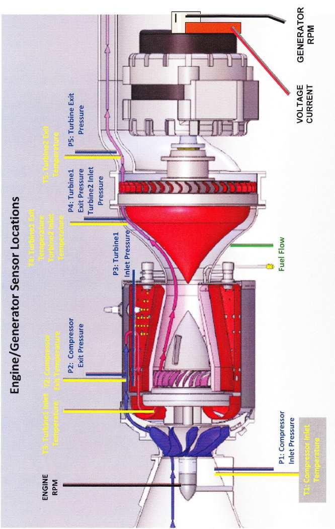
3 How it works! Engine Air Intake Compressor SR-30 TM Jet Engine Power Turbine Engine Thrust Nozzle Thrust Transition Deflector Electrical Alternator Free Turbine Load Supply Outlet Following the cutaway schematic; Air enters the intake of the SR-30 TM Engine. It is compressed by the centrifugal compressor, mixed with fuel and combusted in the combustion chamber, creating thrust which drives the power turbine (the power turbine is connected directly to the compressor and drives it). The thrust then accelerates out the thrust nozzle. In a straight thrust engine, this would be the propelling force to move the object the engine is attached to (such as an aircraft). With TurboGen TM, we direct the thrust through a thrust transition deflector, causing the thrust to drive another turbine wheel called a free turbine (not mechanically connected to engine, only thermodynamically connected). The free turbine drives an electrical alternator which generates electricity to drive an electrical load. Strategic sensors measure operational conditions of the engine and generation system. The following shows sensor details (first for engine, then for generator). 3
4 4
 T1: Compressor Inlet Temperature (Displayed on Data Acquisition Screen) P2: Compressor Exit Temperature (Displayed on Data")
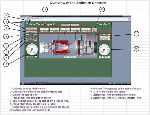
5 SR-30 Gas Turbine Engine / TG-2000 Electrical Generator System Sensor Locations Engine RPM Tachometer Generator: (Displayed on Panel and Data Acquisition Screen as N1 RPM). P1: Compressor Inlet Pressure (Displayed on Data Acquisition Screen) T1: Compressor Inlet Temperature (Displayed on Data Acquisition Screen) P2: Compressor Exit Temperature (Displayed on Data Acquisition Screen) T2: Compressor Exit Temperature (Displayed on Data Acquisition Screen) P3: Turbine1 Inlet Pressure (Displayed on Panel and Data Acquisition Screen) T3: Turbine1 Inlet Temperature (Displayed on Panel as TIT and Data Acquisition Screen) P4: Turbine1 Exit Pressure/Turbine2 Inlet Pressure (Displayed on Data Acquisition Screen) T4: Turbine1 Exit Temperature/Turbine2 Inlet Temperature (Displayed on Data Acquisition Screen) P5: Turbine2 Exit Pressure (Displayed on Data Acquisition Screen) T5: Turbine2 Exit Temperature (Displayed on Panel as EGT and Data Acquisition Screen) Fuel Pressure: (Displayed on Panel) Generator RPM Tachometer Generator: (Displayed on Panel and Data Acquisition Screen as N2 RPM). Voltage and Current: Displayed on Data Acquisition Screen as Voltage, Current and Power TurboGen Virtual Instrument Panel 5
 OPERATIONAL CONTROLS TurboGen Operator Panel 1. MASTER SWITCH, KEYED: Secured control of access and engine operation 2.")
6 TurboGen TM Power System Control Panel Turbine Inlet Temperature Exhaust Gas Temperature RPM Auto Start TM Engine Status 14 Engine Stop Button 1 Power 2 Engine 3 Start 10 Oil 11 Fuel Key Button Pressure Pressure Throttle 4 5 Air Pressure (Air Start) OPERATIONAL CONTROLS TurboGen Operator Panel 1. MASTER SWITCH, KEYED: Secured control of access and engine operation 2. GREEN START BUTTON: Automated Engine Start, Multiple Functions 3. RED STOP BUTTON: Immediate EngineStop, Multiple Functions 4. T-HANDLED POWER LEVER: Engine RPM/Thrust Control, Forward Increases 5. LOAD LEVER (Blue Handle): Controls Excitation Loading on Electric Alternator 6. AUTOSTART LCD DISPLAY: Real Time System Status Automatically Shuts Off Unit if Parameters Exceeded. DIGITAL and ANALOG OPERATOR DISPLAY: Direct visual indication of the following: 7. Digital Turbine Inlet Temperature (TIT) 8. Digital Engine Rotational Speed (RPM) 9. Digital Generator Turbine Rotational Speed (RPM) 10. Analog Oil Pressure 11. Analog Engine Pressure (P3) 12. Analog Fuel Pressure 13. Analog Starting Air Pressure 14. Generator Overspeed Warning Light 6

7 In preparation for system operation and data analysis, please answer the following questions: Fuel Pressure System Operation Purpose: Conduct pre-start, start-up, operation, data gathering and shut down of TurboGen TM Gas Turbine Electrical Generation System. Procedure: Utilize TurboGen TM Operators Manual and follow Section 4.2 Expanded Normal Procedures to perform system pre-start, start-up, operation, data acquisition and shut down. Utilize the data acquisition system to capture the operational values from startup to shut down (covered in Section Data Collection and also covered in detail on the next page of this sample lab). Run Engine throttle up to full speed with Load Lever in pinned position (Fixed Excitation Current). Optional: After full run-up in pinned position, unpin Load Lever and slowly bring it forward (increasing Excitation Current) and then slowly pushing it back (decreasing Excitation Current). A variety of speeds and operating load condition scenarios can be run during this time. WARNING!! CHECK OPERATOR S MANUAL FOR LOAD LEVER/GENERATOR OVER-SPEED CAUTIONS! 7


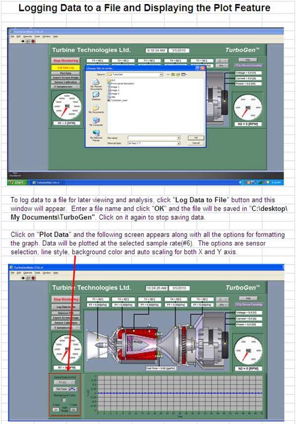
8 DATA COLLECTION Recording and using your data properly is an important part of successfully completing the lab. NOTE: The following steps assume the use of the standard TurboGen Software and default settings as supplied with the TurboGen. Use of non-default setting or other software may necessitate alternative methods or procedures for data collection. Consult the LabView/National Instruments software specific information as required. From Windows, OPEN the TurboGen Software by doubleclicking on the TurboGen 1.0 shortcut icon located on the Windows Desktop. TurboGen 1.0 will start with the Main Display/Control and Channel Configuration Window displayed. NOTE: The computer must be connected to the TurboGen USB port prior to opening the TurboGen software. The TurboGen configuration software is dependent upon the specific DAQ Module serial number as installed in the TurboGen and will not function properly if the DAQ Module cannot be found. If this was done incorrectly, exit the program, attach the USB cable and start over. To verify that the software is communicating with the DAQ Module, open Measurement and Automation from desktop. In menu tree, click on Devices and Interfaces, then, click on NI DAQ This provides and verifies the proper serial number for the on board DAQ system and also verifies that a proper connection to that device is being made. TO PERFORM THE FOLLOWING FUNCTIONS: TurboGen Launch Icon Measurement and Automation Launch Icon Virtual Instrument Panel Software Controls overview are on page 9 Logging Data to File is shown on Page 10 Displaying Plot Feature is shown on Page 10 8
9 9
10 10

11 TurboGen TM Gas Turbine Electrical Generation System Experiment Manual Lab Session #2: TurboGen TM Data Run Plots Purpose: Graphically plot TurboGen TM Run Data in preparation for system analysis and performance calculations. Procedure: Follow the instructions starting on the following pages of this lab session to plot system run data. Plot the following, utilizing MS-Excel Spreadsheet Program: Compressor Inlet/Outlet Pressure vs. Time Compressor Inlet/Outlet Temperature vs. Time Turbine1 (N1) Inlet/Outlet Pressure vs. Time Turbine1 (N1) Inlet/Outlet Temperature vs. Time Turbine 2 (N2)Inlet/Outlet Pressure vs. Time Turbine 2 (N2) Inlet/Outlet Temperature vs. Time Fuel Flow vs. Time Engine RPM vs. Time Generator RPM vs. Time Generator Voltage vs. Time Generator Current vs. Time Generator Power vs. Time Print out plots and order them as listed. Choose and mark an analysis point on each plot for the same time point. For this exercise, pick a spot where engine RPM is at or near its peak during the data run. This will be the basis for system performance analysis calculations. From your plots (specific time mark) and data collected from system run, please record the following: 11

12 Importing Acquisition Data into MS-Excel Spreadsheet A convenient way to analyze TurboGen performance data is to graph the data points using MS-Excel Spreadsheet. To do this, the ASCII data captured during the lab data acquisition must be imported into Excel. Open: MS-Excel on computer desktop Click: File Click: Open Click: C-Drive Click: Program Files Click: TurboGen Click: All Files under Files of Type Click: Next (In Text Import Window, Step 1 of 3) Click: Next (In Text Import Window, Step 2 of 3) Click: Next (In Text Import Window, Step 3 of 3) Your data will now be in spreadsheet form. 12

13 Graphing Data using MS-Excel Spreadsheet Graphing Function (Example) Highlight columns of data desired for graph. For this example, the Time and Voltage column data will be plotted. 13

14 Insert Chart Type: Line Chart Sub Type: Line (first one) Next Accept data range listed by choosing: Next Choose Graph Options and Labels 14


15 Name Graph, Click as New Sheet, Finish Completed Turbine Inlet and Outlet Pressure Graph 15
.")
16 TurboGen TM Gas Turbine Electrical Generation Lab Experiment Manual Lab Session #3: System Analysis Purpose: To perform system performance calculations using First Law Energy Conservation Equation for Steady State, Steady Flow Conditions (SSSF). The data for these calculations comes from the information plotted and recorded in the previous lab session Procedure: Perform requested analysis and calculations. Schematic of Brayton Cycle for Gas Turbine and Cut Away of SR-30 Engine SR-30 Gas Turbine Engine TG-2000 Turbo-Electric Generator Q add 2 3 Combustion Q rej 1 Wk Comp Comp. Turbine 1 Turbine 2 Q rej 4 5 Wk alternat Alt. Power Output 16
17 17


18 TurboGen TM Gas Turbine Power System Lab Experiment Manual Lab Session #4: Engine Performance Analysis Purpose: To perform system performance calculations of the engine at the compressor inlet and nozzle exit. The data for these calculations comes from the information recorded and plotted in a previous lab session Procedure: Perform requested analysis and calculations at this location and operational point. COMPRESSOR INLET Temperature Probe Pitot-Static Tube What is the Pitot-Static Recorded Pressure (Compressor Inlet Pressure) and Air Density at this location and operating condition? 18
19 19

20 TurboGen TM Gas Turbine Power System Lab Experiment Manual Lab Session #5: Electrical Generation Performance Analysis Purpose: To determine optimal operational settings for the SR-30 Gas Turbine Engine to calculate Power Specific Fuel Consumption in the process of generating Electricity. Procedure: Perform requested analysis and calculations that follow. TurboGen generates electricity by thermodynamically spinning a turbine wheel, which drives an electric alternator. A basic electric schematic of the electric alternator system is shown in Figure 1. The alternator consists of two basic components; a rotor and a stator. The rotor is an electromagnet (not permanent), so it needs Excitation Current for it to generate electricity. The rotor spins, creating a voltage The rotor consists of a coil of wire wrapped around an iron core. Current through the wire coil - called "field" current - produces a magnetic field around the core. The strength of the field current determines the strength of the magnetic field. The Excitation Current Stator Rotor Stator Figure 1: Electric Alternator field current is D/C, or direct current. In other words, the current flows in one direction only, and is supplied to the wire coil by a set of brushes and slip rings. The magnetic field produced has, as any magnet, a north and a south pole. The rotor is driven by the alternator pulley, rotating as the engine runs, hence the name "rotor." Surrounding the rotor is another set of coils, three in number, called the stator. The stator is fixed to the shell of the alternator, and does not turn. As the rotor turns within the stator windings, the magnetic field of the rotor sweeps through the stator windings, producing an electrical current in the windings. Because of the rotation of the rotor, an alternating current is produced. As, for example, the north pole of the magnetic field approaches one of the stator windings, there is little coupling taking place, and a weak current is produced, As the rotation continues, the magnetic field moves to the center of the winding, where maximum coupling takes place, and the induced current is at its N S R 20
21 peak. As the rotation continues to the point that the magnetic field is leaving the stator winding, the induced current is small. By this time, the south pole is approaching the winding, producing a weak current in the opposite direction. As this continues, the current produced in each winding plotted against the angle of rotation of the rotor has the form shown in figure 2. The three stator windings are spaced inside the alternator 120 degrees apart, producing three separate sets, or "phases," of output voltages, spaced 120 degrees apart, as shown in figure 3. A Resistive Load R completes the circuit as shown in Figure 1. Calculating Power Specific Fuel Consumption 21
22 Power Specific Fuel Consumption is a measure of fuel consumption of the engine divided by the electric power produced by the generator. When the TurboGen was run and data gathered, the optional strategy was to run the system with the Load Lever pinned (mid-range excitation current) and then unpin the lever and increase excitation to maximum current, then reduce it to minimum current. For the following analysis, a data run with all three options is used (See plotted graphs on pages 25-27). It can be seen that a pinned-only option can still be analyzed. 1. Using your operational run data plots, pull up and print the following graphs: N1 RPM (Engine RPM) plotted over Time. N2 RPM (Generator RPM) plotted over Time Voltage over Time Current over Time Power over Time Fuel Flow over Time 2. Plot analysis points of interest (similar to those shown on graph) for Load Lever Pinned Load Lever Maximum Excitation Load Lever Minimum Excitation Reasonably exact values can be extracted from your Excel data by lining up a graphical time stamp with a particular time line in the data. 3. Looking at data values while the excitation current Load Lever was in the pinned position, pick a specific time marker to view conditions: 22
23 4. Let s go to a marker where excitation current Load Lever was loaded to maximum excitation current: 23
24 5. Let s go to a marker where excitation current Load Lever was loaded to minimum excitation current: 24
25 25
26 26
27 27
TurboGen TM Gas Turbine Electrical Generation System Sample Lab Experiment Procedure
 TurboGen TM Gas Turbine Electrical Generation System Sample Lab Experiment Procedure Lab Session #1: System Overview and Operation Purpose: To gain an understanding of the TurboGen TM Gas Turbine Electrical
Mini-Lab Gas Turbine Power System TM Sample Lab Experiment Manual
 Mini-Lab Gas Turbine Power System TM Sample Lab Experiment Manual Lab Session #1: System Overview and Operation Purpose: To gain an understanding of the Mini-Lab TM Gas Turbine Power System as a whole
WindLab TM Wind Turbine Power System Sample Laboratory Procedure Manual
 WindLab TM Wind Turbine Power System Sample Laboratory Procedure Manual WindLab TM is a scaled Wind Turbine Electrical Generation System, designed to function like a full-sized wind turbine system. It
ME3264: LAB 9 Gas Turbine Power System
 OBJECTIVE ME3264: LAB 9 Gas Turbine Power System Professor Chih-Jen Sung Spring 2013 A fully integrated jet propulsion system will be used for the study of thermodynamic and operating principles of gas
Armature Reaction and Saturation Effect
 Exercise 3-1 Armature Reaction and Saturation Effect EXERCISE OBJECTIVE When you have completed this exercise, you will be able to demonstrate some of the effects of armature reaction and saturation in
KS3 Revision. 8J Magnets and Electromagnets
 KS3 Revision 8J Magnets and Electromagnets 1 of 29 Boardworks Ltd 2007 Contents 8J Magnets and Electromagnets Magnetic materials Magnetic fields Electromagnets Summary activities 2 of 29 Boardworks Ltd
Permanent Magnet DC Motor
 Renewable Energy Permanent Magnet DC Motor Courseware Sample 86357-F0 A RENEWABLE ENERGY PERMANENT MAGNET DC MOTOR Courseware Sample by the staff of Lab-Volt Ltd. Copyright 2011 Lab-Volt Ltd. All rights
Faraday's Law of Induction
 Purpose Theory Faraday's Law of Induction a. To investigate the emf induced in a coil that is swinging through a magnetic field; b. To investigate the energy conversion from mechanical energy to electrical
Renewable Energy Systems 13
 Renewable Energy Systems 13 Buchla, Kissell, Floyd Chapter Outline Generators 13 Buchla, Kissell, Floyd 13-1 MAGNETISM AND ELECTROMAGNETISM 13-2 DC GENERATORS 13-3 AC SYNCHRONOUS GENERATORS 13-4 AC INDUCTION
Principles of Doubly-Fed Induction Generators (DFIG)
") Renewable Energy Principles of Doubly-Fed Induction Generators (DFIG) Courseware Sample 86376-F0 A RENEWABLE ENERGY PRINCIPLES OF DOUBLY-FED INDUCTION GENERATORS (DFIG) Courseware Sample by the staff
Renewable Energy Principles of Doubly-Fed Induction Generators (DFIG) Courseware Sample 86376-F0 A RENEWABLE ENERGY PRINCIPLES OF DOUBLY-FED INDUCTION GENERATORS (DFIG) Courseware Sample by the staff
University of TN Chattanooga Physics 1040L 8/28/2012
 PHYSICS 1040L LAB 5: MAGNETIC FIELD Objectives: 1. Determine the relationship between magnetic field and the current in a solenoid. 2. Determine the relationship between magnetic field and the number of
Lab 6: Wind Turbine Generators
 Lab 6: Wind Turbine Generators Name: Pre Lab Tip speed ratio: Tip speed ratio (TSR) is defined as: Ω, where Ω=angular velocity of wind, and R=radius of rotor (blade length). If the rotational speed of
NORTHERN ILLINOIS UNIVERSITY PHYSICS DEPARTMENT. Physics 211 E&M and Quantum Physics Spring Lab #6: Magnetic Fields
 NORTHERN ILLINOIS UNIVERSITY PHYSICS DEPARTMENT Physics 211 E&M and Quantum Physics Spring 2018 Lab #6: Magnetic Fields Lab Writeup Due: Mon/Wed/Thu/Fri, March 5/7/8/9, 2018 Background Magnetic fields
GENERAL The AuRACLE Engine Management System primary display provides a graphical representation of the following engine instrumentation:
 GENERAL The AuRACLE Engine Management System primary display provides a graphical representation of the following engine instrumentation: o Manifold Pressure (MAP) o RPM o Fuel Flow (FF) o Turbine Inlet
Iowa State University Electrical and Computer Engineering. E E 452. Electric Machines and Power Electronic Drives
 Electrical and Computer Engineering E E 452. Electric Machines and Power Electronic Drives Laboratory #12 Induction Machine Parameter Identification Summary The squirrel-cage induction machine equivalent
SPARKER DC-CDI-P2 HARDWARE
 SPARKER DC-CDI-P2 SPARKER DC-CDI-P2 RACE is a capacitive ignition unit for road motorcycles. The ignition unit can be programmed via a computer and it is fully tunable as regards ignition timing. It contains
Faraday's Law of Induction
 Induction EX-9914 Page 1 of 6 EQUIPMENT Faraday's Law of Induction INCLUDED: 1 Induction Wand EM-8099 1 Variable Gap Lab Magnet EM-8641 1 Large Rod Stand ME-8735 2 45 cm Long Steel Rod ME-8736 1 Multi
Gas Turbine. Somsak Chaiyapinunt
 245362 Gas Turbine Somsak Chaiyapinunt Gas turbines, like other heat engines, achieve conversion of heat energy of a fuel into mechanical energy by carrying out a sequence of processes, i.e. a cycle, on
MOTORS. Part 2: The Stepping Motor July 8, 2015 ELEC This lab must be handed in at the end of the lab period
 MOTORS Part 2: The Stepping Motor July 8, 2015 ELEC 3105 This lab must be handed in at the end of the lab period 1.0 Introduction The objective of this lab is to examine the operation of a typical stepping
Energy Conversions Questions CfE
 Energy Conversions Questions CfE 1) A 0.02kg mass is held at a height of 0.8m above the ground. a) Calculate the gravitational potential energy stored in the mass before it is dropped. b) i) State the
Permanent Magnet DC Motor Operating as a Generator
 Exercise 2 Permanent Magnet DC Motor Operating as a Generator EXERCIE OBJECTIVE When you have completed this exercise, you will be familiar with the construction of permanent magnet dc motors as well as
ELECTRIC MACHINES EUROLAB 0.3 kw
 index SINGLE-PHASE MOTORS SPLIT-PHASE MOTOR DL 30130 CAPACITOR MOTOR DL 30140 UNIVERSAL MOTOR DL 30150 REPULSION MOTOR DL 30170 THREE PHASE ASYNCHRONOUS MOTORS SQUIRREL CAGE THREE PHASE ASYNCHRONOUS MOTOR
Photographs of large cities, such as Seattle, Washington, are visible reminders of how much people rely on electrical energy.
 Photographs of large cities, such as Seattle, Washington, are visible reminders of how much people rely on electrical energy. Generating Electric Current How is voltage induced in a conductor? According
Series 1580 dynamometer and thrust stand datasheet
 Series 1580 dynamometer and thrust stand datasheet Typical use Inrunner and outrunner brushless motor characterization (0 40A) Propeller characterization Servo testing and control Battery endurance testing
UNIVERSITY OF MINNESOTA DULUTH DEPARTMENT OF CHEMICAL ENGINEERING ChE Centrifugal Pump(Armfield)
") UNIVERSITY OF MINNESOTA DULUTH DEPARTMENT OF CHEMICAL ENGINEERING ChE 3211-4211 Centrifugal Pump(Armfield) OBJECTIVE The objective of this experiment is to investigate the operating characteristics of
UNIVERSITY OF MINNESOTA DULUTH DEPARTMENT OF CHEMICAL ENGINEERING ChE 3211-4211 Centrifugal Pump(Armfield) OBJECTIVE The objective of this experiment is to investigate the operating characteristics of
Evaluation copy. The Magnetic Field in a Slinky. computer OBJECTIVES MATERIALS INITIAL SETUP
 The Magnetic Field in a Slinky Computer 26 A solenoid is made by taking a tube and wrapping it with many turns of wire. A metal Slinky is the same shape and will serve as our solenoid. When a current passes
The Starter motor. Student booklet
 The Starter motor Student booklet The Starter motor - INDEX - 2006-04-07-13:20 The Starter motor The starter motor is an electrical motor and the electric motor is all about magnets and magnetism: A motor
Miscellaneous Measuring Devices
 Instrumentation 7 C H A P T E R Miscellaneous Measuring Devices Objectives After completing this chapter, you will be able to: Define terms associated with miscellaneous measuring devices: vibration rotational
The Magnetic Field in a Slinky
 The Magnetic Field in a Slinky A solenoid is made by taking a tube and wrapping it with many turns of wire. A metal Slinky is the same shape and will serve as our solenoid. When a current passes through
Experiment 3. The Direct Current Motor Part II OBJECTIVE. To locate the neutral brush position. To learn the basic motor wiring connections.
 Experiment 3 The Direct Current Motor Part II OBJECTIVE To locate the neutral brush position. To learn the basic motor wiring connections. To observe the operating characteristics of series and shunt connected
BELT-DRIVEN ALTERNATORS
 CHAPTER 13 BELT-DRIVEN ALTERNATORS INTRODUCTION A generator is a machine that converts mechanical energy into electrical energy using the principle of magnetic induction. This principle is based on the
Exercise 2-1. The Separately-Excited DC Motor N S EXERCISE OBJECTIVE DISCUSSION OUTLINE DISCUSSION. Simplified equivalent circuit of a dc motor
 Exercise 2-1 The Separately-Excited DC Motor EXERCISE OBJECTIVE When you have completed this exercise, you will be able to demonstrate the main operating characteristics of a separately-excited dc motor
WB 23 & WB 27. High-Speed Eddy-Current Dynamometers WB 23 & WB 27. Features. Description. Operating principles
 WB 23 & WB 27 High-Speed Eddy-Current Dynamometers Magtrol offers 3 types of dynamometer brakes to absorb load: Hysteresis, Eddy-Current and Magnetic Powder. Each type of Dynamometer has advantages and
ElPower script. Contents. ElPower script diagnostics of the engine starting and charging system
 ElPower script Contents 1. Purpose...2 2. Recording the waveforms and starting the script...3 3. Analysis results...5 3.1 The "Report" tab...5 3.2 The "Results of analysis" tab...6 3.3 The "Graphics" tab...9
10.0 Alternator Test
 10.0 Alternator Test An alternator is the device used to produce the electricity the car needs to run and to keep the battery charged. The alternator uses the principle of electromagnetic induction to
Experiment 6: Induction
 Experiment 6: Induction Part 1. Faraday s Law. You will send a current which changes at a known rate through a solenoid. From this and the solenoid s dimensions you can determine the rate the flux through
Fuel Strategy (Exponential Decay)
") By Ten80 Education Fuel Strategy (Exponential Decay) STEM Lesson for TI-Nspire Technology Objective: Collect data and analyze the data using graphs and regressions to understand conservation of energy
By Ten80 Education Fuel Strategy (Exponential Decay) STEM Lesson for TI-Nspire Technology Objective: Collect data and analyze the data using graphs and regressions to understand conservation of energy
V PicoScope NVH Diagnostics Overview
 13042.13V PicoScope NVH Diagnostics Overview The CH-51450 PicoScope is a computer software-based Noise, Vibration and Harshness, or N-V-H tool. This tool has several important components for NVH diagnosis:
Just what is an alternator?
 Just what is an alternator? An alternator is the device used to produce the electricity the car needs to run and to keep the battery charged. The battery is the heart of your electrical system. But you
Science 30 Unit C Electromagnetic Energy
 Science 30 Unit C Electromagnetic Energy Outcome 1: Students will explain field theory and analyze its applications in technologies used to produce, transmit and transform electrical energy. Specific Outcome
ECE 5671/6671 Lab 5 Squirrel-Cage Induction Generator (SCIG)
") ECE 5671/6671 Lab 5 Squirrel-Cage Induction Generator (SCIG) 1. Introduction 1.1 Objectives The objective of this lab is to connect a SCIG generator directly to the grid and measure the power produced
ECE 5671/6671 Lab 5 Squirrel-Cage Induction Generator (SCIG) 1. Introduction 1.1 Objectives The objective of this lab is to connect a SCIG generator directly to the grid and measure the power produced
Development and Implementation of Interactive/Visual Software for Simple Aircraft Gas Turbine Design
 Development and Implementation of Interactive/Visual Software for Simple Aircraft Gas Turbine Design Afshin J. Ghajar, Ronald D. Delahoussaye, Vandan V. Nayak School of Mechanical and Aerospace Engineering,
Automated Seat Belt Switch Defect Detector
 pp. 10-16 Krishi Sanskriti Publications http://www.krishisanskriti.org/publication.html Automated Seat Belt Switch Defect Detector Department of Electrical and Computer Engineering, Sri Lanka Institute
Chapter 8 Magnetism and Its Uses. Section 1: Magnetism Section 2: Electricity and Magnetism Section 3: Producing Electric Current
 Chapter 8 Magnetism and Its Uses Section 1: Magnetism Section 2: Electricity and Magnetism Section 3: Producing Electric Current Section 1: Magnetism Standard 6: Demonstrate an understanding of the nature,
Prop-Tech Vacuum Analyzer
 Electronic Carburettor / Injector Balancing Tool 1. WARNING THIS PRODUCT IS A PROFESSIONAL TOOL WHICH SHOULD ONLY BE OPERATED BY A COMPETENT TRAINED TECHNICIAN AND ONLY FOR THE PURPOSE WHICH IT WAS DESIGNED
EE 742 Chap. 7: Wind Power Generation. Y. Baghzouz
 EE 742 Chap. 7: Wind Power Generation Y. Baghzouz Wind Energy 101: See Video Link Below http://energy.gov/eere/videos/energy-101- wind-turbines-2014-update Wind Power Inland and Offshore Growth in Wind
Lab Electrical Power Engineering I
 INSTITUT FÜR ELEKTRISCHE MASCHINEN RHEINISCH-WESTFÄLISCHE TECHNISCHE HOCHSCHULE AACHEN Lab Electrical Power Engineering I Test 3: Induction machine with squirrel cage rotor and slip ring rotor 1 Experiment
Fachpraktikum Elektrische Maschinen. Experiments with a 400/ 690 V Squirrel Cage Induction Machine
 Fachpraktikum Elektrische Maschinen Experiments with a 400/ 690 V Squirrel Cage Induction Machine Prepared by Arda Tüysüz January 2013 1. Questions to answer before the experiment - Describe the operation
Unit 8 ~ Learning Guide Name:
 Unit 8 ~ Learning Guide Name: Instructions: Using a pencil, complete the following notes as you work through the related lessons. Show ALL work as is explained in the lessons. You are required to have
EE 742 Chap. 7: Wind Power Generation. Y. Baghzouz Fall 2011
 EE 742 Chap. 7: Wind Power Generation Y. Baghzouz Fall 2011 Overview Environmental pressures have led many countries to set ambitious goals of renewable energy generation. Wind energy is the dominant renewable
Motor-CAD End Winding Spray Cooling Model
 Motor-CAD End Winding Spray Cooling Model Description Motor spray cooling is where the end winding is cooled by passing a fluid down the shaft and then firing it at the end winding through nozzles at the
Glow Plug for E Series Only
 Charging the Battery - Do not charge the battery, with a charger using negative discharge pulses, when connected to the ECU. This will destroy the electronics of the ECU. The only method is to disconnect
The Wound-Rotor Induction Motor Part I
 Experiment 1 The Wound-Rotor Induction Motor Part I OBJECTIVE To examine the construction of the three-phase wound-rotor induction motor. To understand exciting current, synchronous speed and slip in a
I.E.S. Cristo Del Socorro de Luanco. Magnetism
 Magnetism Magnetism is a force of attraction or repulsion that acts at a distance. It is due to a magnetic field, which is caused by moving electrically charged particles or is inherent in magnetic objects
REV F2.0. User's Manual. Hydraulic ABS (HABS) Hydraulic Power Brake (HPB) Page 1 of 28
 Hydraulic Power Brake (HPB) Page 1 of 28") REV F2.0 User's Manual Hydraulic ABS (HABS) Hydraulic Power Brake (HPB) Page 1 of 28 Table of Contents INTRODUCTION...4 Starting TOOLBOX Software... 5 MAIN MENU...6 System Setup... 6 Language... 7 Select
REV F2.0 User's Manual Hydraulic ABS (HABS) Hydraulic Power Brake (HPB) Page 1 of 28 Table of Contents INTRODUCTION...4 Starting TOOLBOX Software... 5 MAIN MENU...6 System Setup... 6 Language... 7 Select
Introduction: Supplied to 360 Test Labs... Battery packs as follows:
 2007 Introduction: 360 Test Labs has been retained to measure the lifetime of four different types of battery packs when connected to a typical LCD Point-Of-Purchase display (e.g., 5.5 with cycling LED
AERONAUTICAL ENGINEERING
 AERONAUTICAL ENGINEERING SHIBIN MOHAMED Asst. Professor Dept. of Mechanical Engineering Al Ameen Engineering College Al- Ameen Engg. College 1 Aerodynamics-Basics These fundamental basics first must be
Unit 2: Electricity and Energy Resources
 8 8 Table of Contents Unit 2: Electricity and Energy Resources Chapter 8: Magnetism and Its Uses 8.1: Magnetism 8.2: Electricity and Magnetism 8.3: Producing Electric Current 8.1 Magnets More than 2,000
TORQUE-MOTORS. as Actuators in Intake and Exhaust System. SONCEBOZ Rue Rosselet-Challandes 5 CH-2605 Sonceboz.
 TORQUE-MOTORS as Actuators in Intake and Exhaust System SONCEBOZ Rue Rosselet-Challandes 5 CH-2605 Sonceboz Tel.: +41 / 32-488 11 11 Fax: +41 / 32-488 11 00 info@sonceboz.com www.sonceboz.com as Actuators
3/31/2016. Unit 2: Electricity and Energy Resources. Magnets. Magnets. Magnetic Force. Magnetic Field. Chapter 8: Magnetism and Its Uses
 8 8 Table of Contents Unit 2: Electricity and Energy Resources Chapter 8: and Its Uses : : Electricity and : Magnets More than 2,000 years ago Greeks discovered deposits of a mineral that was a natural
Lesson Plan: Electricity and Magnetism (~100 minutes)
") Lesson Plan: Electricity and Magnetism (~100 minutes) Concepts 1. Electricity and magnetism are fundamentally related. 2. Just as electric charge produced an electric field, electric current produces a
Lesson Plan: Electricity and Magnetism (~100 minutes) Concepts 1. Electricity and magnetism are fundamentally related. 2. Just as electric charge produced an electric field, electric current produces a
2014 ELECTRICAL TECHNOLOGY
 SET - 1 II B. Tech I Semester Regular Examinations, March 2014 ELECTRICAL TECHNOLOGY (Com. to ECE, EIE, BME) Time: 3 hours Max. Marks: 75 Answer any FIVE Questions All Questions carry Equal Marks ~~~~~~~~~~~~~~~~~~~~~~~~~~
POWERLINK Eddy Current Brake for Engine Test Configuration reference
 POWERLINK Eddy Current Brake for Engine Test Configuration reference www.powerlinkpt.com info@powerlinkpt.com 1. Major components 1.1 GW series Eddy Current Dynamometer The system uses the eddy current
Impulse, Momentum, and Energy Procedure
 Impulse, Momentum, and Energy Procedure OBJECTIVE In this lab, you will verify the Impulse-Momentum Theorem by investigating the collision of a moving cart with a fixed spring. You will also use the Work-Energy
SP4 DOCUMENTATION. 1. SP4 Reference manual SP4 console.
 SP4 DOCUMENTATION 1. SP4 Reference manual.... 1 1.1. SP4 console... 1 1.2 Configuration... 3 1.3 SP4 I/O module.... 6 2. Dynamometer Installation... 7 2.1. Installation parts.... 8 2.2. Connectors and
CP Data Sheet I-CAM Introduction: I-CAM, Integrated Calibration And Automated Mapping CP Engineering Systems Ltd.
 I-CAM Introduction: I-CAM, Integrated Calibration And Automated Mapping as a component add-on to the advanced CADET V12 Engine and Vehicle Test System, provides a state-of-the-art, automatic engine spark
CHAPTER 6 INTRODUCTION TO MOTORS AND GENERATORS
 CHAPTER 6 INTRODUCTION TO MOTORS AND GENERATORS Objective Describe the necessary conditions for motor and generator operation. Calculate the force on a conductor carrying current in the presence of the
Engine Performance Analysis
 Engine Performance Analysis Introduction The basics of engine performance analysis The parameters and tools used in engine performance analysis Introduction Parametric cycle analysis: Independently selected
Pre-lab Questions: Please review chapters 19 and 20 of your textbook
 Introduction Magnetism and electricity are closely related. Moving charges make magnetic fields. Wires carrying electrical current in a part of space where there is a magnetic field experience a force.
RENEWABLE ENERGY TRAINER
 RENEWABLE ENERGY TRAINER Our most advanced training platform, for your most advanced experiments. Explores the cutting-edge science behind renewable energy engineering Features dozens of customizable expansion
Unit 32 Three-Phase Alternators
 Unit 32 Three-Phase Alternators Objectives: Discuss the operation of a three-phase alternator. Explain the effect of rotation speed on frequency. Explain the effect of field excitation on output voltage.
Electrical Theory. Generator Theory. PJM State & Member Training Dept. PJM /22/2018
 Electrical Theory Generator Theory PJM State & Member Training Dept. PJM 2018 Objectives The student will be able to: Describe the process of electromagnetic induction Identify the major components of
EPAS Desktop Pro Software User Manual
 Software User Manual Issue 1.10 Contents 1 Introduction 4 1.1 What is EPAS Desktop Pro? 4 1.2 About This Manual 4 1.3 Typographical Conventions 5 1.4 Getting Technical Support 5 2 Getting Started 6 2.1
INTEGRATED ENGINE INSTRUMENT SYSTEMS
 All INTEGRATED ENGINE INSTRUMENT SYSTEMS. DESCRIPTION This section describes that portion of the engine indicating system which is used to analyze engine performance, temperature, and condition. Serials
SPH3U UNIVERSITY PHYSICS
 SPH3U UNIVERSITY PHYSICS ELECTRICITY & MAGNETISM L (P.599-604) The large-scale production of electrical energy that we have today is possible because of electromagnetic induction. The electric generator,
PRODUCT REQUIREMENTS
 Model 622 Technical Specifications Page 1 of 6 GAS TURBINE AND JET ENGINE COMPONENT TESTING Mass Airflow Test Stand Model 622 Automatic Airflow Test Stand Dimensions: 67" H x 57" W x 42" D 1702mm H x 1448mm
Chapter 17 Notes. Magnetism is created by moving charges.
 Chapter 17 Notes Section 17.1 Electric Current and Magnetism Hans Christian Øersted (1819), a Danish physicist and chemist - compass needle near a wire circuit and with current flowing through the wire,
Chapter 5. Design of Control Mechanism of Variable Suspension System. 5.1: Introduction: Objective of the Mechanism:
 123 Chapter 5 Design of Control Mechanism of Variable Suspension System 5.1: Introduction: Objective of the Mechanism: In this section, Design, control and working of the control mechanism for varying
Issue 2.0 December EPAS Midi User Manual EPAS35
 Issue 2.0 December 2017 EPAS Midi EPAS35 CONTENTS 1 Introduction 4 1.1 What is EPAS Desktop Pro? 4 1.2 About This Manual 4 1.3 Typographical Conventions 5 1.4 Getting Technical Support 5 2 Getting Started
Welcome to Aerospace Engineering
 Welcome to Aerospace Engineering DESIGN-CENTERED INTRODUCTION TO AEROSPACE ENGINEERING Notes 5 Topics 1. Course Organization 2. Today's Dreams in Various Speed Ranges 3. Designing a Flight Vehicle: Route
Magnets and magnetism
 Chapter 2 Electromagnetism Section 1 Magnets and magnetism Vocabulary: magnet magnetic pole magnetic force Properties of Magnets Magnetic Poles on a magnet, the magnetic poles are the locations where the
Period 16 Activity Sheet: Motors and Generators
 Name Section Period 16 Activity Sheet: Motors and Generators Activity 16.1: How Are Electric Motors and Generators Related? a) Generators. 1) Attach a hand-cranked generator to a small motor and turn the
EEE3441 Electrical Machines Department of Electrical Engineering. Lecture. Introduction to Electrical Machines
 Department of Electrical Engineering Lecture Introduction to Electrical Machines 1 In this Lecture Induction motors and synchronous machines are introduced Production of rotating magnetic field Three-phase
Electrical Machines-I (EE-241) For S.E (EE)
 For S.E (EE)") PRACTICAL WORK BOOK For Academic Session 2013 Electrical Machines-I (EE-241) For S.E (EE) Name: Roll Number: Class: Batch: Department : Semester/Term: NED University of Engineer ing & Technology Electrical
PRACTICAL WORK BOOK For Academic Session 2013 Electrical Machines-I (EE-241) For S.E (EE) Name: Roll Number: Class: Batch: Department : Semester/Term: NED University of Engineer ing & Technology Electrical
Exploring the Energy Grid Grades 6-8. Name:
 Exploring the Energy Grid Grades 6-8 Name: Exploration 1 Rapidly turn the handles clockwise on all three generators at the end of the table, watching the System Voltage panel: 1. Draw the needle when the
Begin to Use The New ESC: Before use the new ESC please carefully check every connections are correct or not. Yellow motor wire B Blue motor wire A
 HIMOTO ZTW Brushless Electronic Speed Control for car or truck Thank you for purchasing ZTW Brushless Electronic Speed Controller(ESC). The ZTW electronic speed control (ESC) is specifically designed for
User Manual WatchPower App
 User Manual WatchPower App Management Software for Inverter Table of Contents 1. Introduction... 1 2. WatchPower App Install and Uninstall... 1 2.1. System Requirement... 1 2.2. Software Install... 1 2.3.
Remy HVH250 Application Manual Remy HVH250 Application Manual
 Preliminary Draft HVH250 MotorManual20110407.doc Page 1 of 31 TABLE OF CONTENTS 1. INTRODUCTION...3 2. SYSTEM OVERVIEW...3 2.1 Installation Overview...3 2.2 Motor Overview...3 3. HVH MOTOR TYPICAL APPLICATIONS...4
Mr. Freeze QUALITATIVE QUESTIONS
 QUALITATIVE QUESTIONS Many of the questions that follow refer to the graphs of data collected when riding Mr. Freeze with high tech data collection vests. With your I.D., you can borrow a vest without
Chapter 22: Electric motors and electromagnetic induction
 Chapter 22: Electric motors and electromagnetic induction The motor effect movement from electricity When a current is passed through a wire placed in a magnetic field a force is produced which acts on
PI Electrical Equipment - Course PI 30.2 MOTORS
 Electrical Equipment - Course PI 30.2 MOTORS OBJECTIVES On completion of this module the student will be able to: 1. Briefly explain, in writing, "shaft rotation" as an interaction of stator and rotor
Chapter 4 Ignition & Electrical Systems
 Chapter 4 Ignition & Electrical Systems Chapter 4 Section A Study Aid Questions Fill in the Blanks 1. Ignition systems can be divided into two classifications: systems or systems for reciprocating engines.
Series 1780 Dynamometer V2 Datasheet
 Series 1780 Dynamometer V2 Datasheet Typical use Outrunner brushless motor characterization 25 kgf / 0-100 A 40 kgf / 0-150 A (Plus) Propeller characterization up to 47 Servo testing and control Battery
Load Test On 3 Phase Slip Ring Induction Motor Lab Manual
 Load Test On 3 Phase Slip Ring Induction Motor Lab Manual Electrical engineering machine lab manual. Brake test on three phase squirrel cage induction motor. No-load &, blocked rotor tests on three phase
Universal computer aided design for electrical machines
 Neonode Inc From the SelectedWorks of Dr. Rozita Teymourzadeh, CEng. 2012 Universal computer aided design for electrical machines Aravind CV Grace I Rozita Teymourzadeh Rajkumar R Raj R, et al. Available
Exercise 7. Thyristor Three-Phase Rectifier/Inverter EXERCISE OBJECTIVE DISCUSSION OUTLINE DISCUSSION. Thyristor three-phase rectifier/inverter
 Exercise 7 Thyristor Three-Phase Rectifier/Inverter EXERCISE OBJECTIVE When you have completed this exercise, you will know what a thyristor threephase rectifier/limiter (thyristor three-phase bridge)
Air-Cooled Eddy Current ED Series Engine Dynamometers
 Air-Cooled Eddy Current ED Series Engine Dynamometers ED Series Air-Cooled Engine Dynamometers Mustang s ED Series Air-Cooled Engine Dynamometers are the answer for most engine testing applications due
Air-Cooled Eddy Current Engine Dynamometers
 Air-Cooled Eddy Current Engine Dynamometers Mustang s ED Series Air-Cooled Engine Dynamometers are the answer for ED Series Engine due Dynamometers most engine Air-Cooled testing applications to their
QUESTION BANK SPECIAL ELECTRICAL MACHINES
 SEVENTH SEMESTER EEE QUESTION BANK SPECIAL ELECTRICAL MACHINES TWO MARK QUESTIONS 1. What is a synchronous reluctance 2. What are the types of rotor in synchronous reluctance 3. Mention some applications
USV Ultra Shear Viscometer
 USV Ultra Shear Viscometer A computer controlled instrument capable of fully automatic viscosity measurements at 10,000,000 reciprocal seconds Viscosity measurement background Accurate measurement of dynamic