Mini-Lab Gas Turbine Power System TM Sample Lab Experiment Manual
|
|
|
- Catherine Parker
- 6 years ago
- Views:
Transcription

1 Mini-Lab Gas Turbine Power System TM Sample Lab Experiment Manual Lab Session #1: System Overview and Operation Purpose: To gain an understanding of the Mini-Lab TM Gas Turbine Power System as a whole and details of engine sensors and controls making up the system. This will prepare you for operation of the system. System shown with optional Hush Kit TM Sound Suppressor System Note: Sample lab does not replace Mini-Lab TM Gas Turbine Power System Operator s Manual. Please refer to manual for detailed system operational and safety instructions.
 T1: Compressor Inlet Temperature (Displayed on Data Acquisition Screen) P2: Compressor Exit Temperature (Displayed on Data")
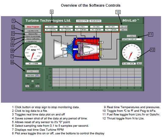
2 SR-30 Gas Turbine Cutaway Engine Sensor Locations RPM Tachometer Generator: (Displayed on Panel as RPM and Data Acquisition Screen). P1: Compressor Inlet Pressure (Displayed on Data Acquisition Screen) T1: Compressor Inlet Temperature (Displayed on Data Acquisition Screen) P2: Compressor Exit Temperature (Displayed on Data Acquisition Screen) T2: Compressor Exit Temperature (Displayed on Data Acquisition Screen) P3: Turbine Inlet Pressure (Displayed on Panel and Data Acquisition Screen) T3: Turbine Inlet Temperature (Displayed on Panel as TIT and Data Acquisition Screen) P4: Turbine Exit Pressure (Displayed on Data Acquisition Screen) T4: Turbine Exit Temperature (Displayed on Data Acquisition Screen) P5: Exhaust Gas Pressure (Displayed on Data Acquisition Screen) T5: Exhaust Gas Temperature (Displayed on Panel as EGT and Data Acquisition Screen) Fuel Pressure: (Displayed on Panel) 1


3 Mini-Lab TM Gas Turbine Power System Control Panel Turbine Inlet Temperature Exhaust Gas Temperature RPM Auto Start TM Engine Status Throttle Power Key Engine Start Button Oil Pressure Fuel Pressure Engine Stop Button Turbine Inlet Temp Air Pressure (Air Start) Data Acquisition Computer Connects to unit s data acquisition system via USB port. Displays and captures data for operation and analysis. 2
4 In preparation for system operation and data analysis, please answer the following questions: Determine the fuel you are using to power your system. What is the energy content per unit volume of fuel? What is the fuel s density per unit volume? Barometric Pressure Fuel Pressure What is the present barometric pressure in your area? Why would barometric pressure be important when planning to operate the Gas Turbine System? What will be your reliable source for accurate barometric pressure readings? System Operation Purpose: Conduct pre-start, start-up, operation, data gathering and shut down of Mini-Lab TM Gas Turbine Power System. Procedure: Utilize Mini-Lab TM Operators Manual and follow Section 4.2 Expanded Normal Procedures to perform system pre-start, start-up, operation, data acquisition and shut down. Utilize the data acquisition system to capture the operational values from startup to shut down (covered in Section Data Collection and also covered in detail on the next page of this sample lab). 3


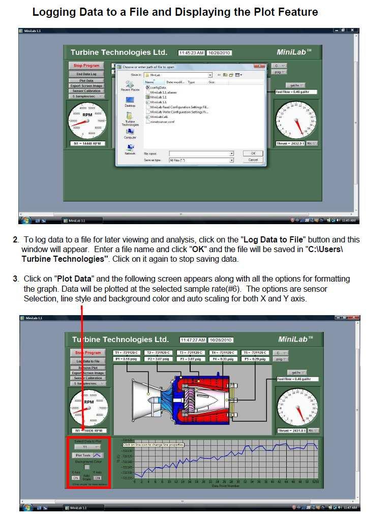
5 DATA COLLECTION Recording and using your data properly is an important part of successfully completing the lab. NOTE: The following steps assume the use of the standard MiniLab Software and default settings as supplied with the MiniLab. Use of non-default setting or other software may necessitate alternative methods or procedures for data collection. Consult the LabView/National Instruments software specific information as required. From Windows, OPEN the MiniLab Software by doubleclicking on the MiniLab 1.1 shortcut icon located on the Windows Desktop. MiniLab 1.1 will start with the Main Display/Control and Channel Configuration Window displayed. MiniLab 1.1 NOTE: The computer must be connected to the MiniLab USB port prior to opening the MiniLab software. The MiniLab configuration software is dependent upon the specific DAQ Module serial number as installed in the MiniLab and will not function properly if the DAQ Module cannot be found. If this was done incorrectly, exit the program, attach the USB cable and start over. To verify that the software is communicating with the DAQ Module, open Measurement and Automation from desktop. In menu tree, click on Devices and Interfaces, then, click on NI DAQ This provides and verifies the proper serial number for the on board DAQ system and also verifies that a proper connection to that device is being made. TO PERFORM THE FOLLOWING FUNCTIONS: MiniLab Launch Icon Measurement and Automation Launch Icon Virtual Instrument Panel Software Controls overview are on page 5 Logging Data to File is shown on Page 6 Displaying Plot Feature is shown on Page 6 4
6 5
7 6

8 Mini-Lab TM Gas Turbine Lab Power System Experiment Manual Lab Session #2: Mini-Lab TM Data Run Plots Purpose: Graphically plot Mini-Lab TM Gas Turbine Run Data in preparation for system analysis and performance calculations. Procedure: Follow the instructions starting on the following pages of this lab session to plot system run data. Plot the following, utilizing MS-Excel Spreadsheet Program: Compressor Inlet/Outlet Pressure vs. Time Compressor Inlet/Outlet Temperature vs. Time Turbine Inlet/Outlet Pressure vs. Time Turbine Inlet/Outlet Temperature vs. Time Exhaust Gas Temperature (EGT) vs. Time Fuel Flow vs. Time RPM vs. Time Thrust vs. Time Fuel Flow and Thrust vs. Time (on one plot) Print out plots and order them as listed. Choose and mark an analysis point on each plot for the same time point. For this exercise, pick a spot where engine RPM is at or near its peak during the data run. This will be the basis for system performance analysis calculations. From your plots (specific time mark) and data collected from system run, please record the following: Date of Run: Time: Atmospheric Pressure: Compressor Inlet Pressure: Compressor Exit Pressure: Turbine Inlet Pressure: Turbine Exit Pressure: Nozzle Exit Pressure: Fuel Flow: RPM: Thrust: Compressor Inlet Temperature: Compressor Exit Temperature: Turbine Inlet Temperature: Turbine Exit Temperature: EGT: 7

9 Importing Acquisition Data into MS-Excel Spreadsheet A convenient way to analyze MiniLab performance data is to graph the data points using MS-Excel Spreadsheet. To do this, the ASCII data captured during the lab data acquisition must be imported into Excel. Open: MS-Excel on computer desktop Click: File Click: Open Click: C-Drive Click: Users\Turbine Technologies Click: MiniLab Click: All Files under Files of Type Click: Next (In Text Import Window, Step 1 of 3) Click: Next (In Text Import Window, Step 2 of 3) Click: Finish (In Text Import Window, Step 3 of 3) Your data will now be in spreadsheet form. 8


10 Graphing Data using MS-Excel Spreadsheet Graphing Function Highlight columns of data desired for graph. For this example, the Time and BP column data will be plotted. Chart Type: Line Chart Sub Type: Line (first one) Next Accept data range listed by choosing: Next 9


11 Choose Graph Options and Labels Name Graph, Click as New Sheet, Finish Completed Turbine Inlet and Outlet Pressure Graph 10
. The data for these calculations comes from the information plotted and recorded in the previous lab session Procedure: Perform requested analysis and calculations.")
12 Mini-Lab TM Gas Turbine Lab Experiment Manual Lab Session #3: System Analysis Purpose: To perform system performance calculations using First Law Energy Conservation Equation for Steady State, Steady Flow Conditions (SSSF). The data for these calculations comes from the information plotted and recorded in the previous lab session Procedure: Perform requested analysis and calculations. Schematic of Brayton Cycle for Gas Turbine and Cut Away of SR-30 Engine 3 Q add 2 4 Wk cycle Combustor 1 Wk comp Turbine Compressor Q rej 11
 For the Compression Stage, Find Specific Work Done by the Compressor (1-2). 2.) For Combustion Stage, Find Specific Energy Added by the Fuel (2-3). 3.")
13 For the analysis point chosen in Lab Session #2, find the Specific Enthalpy at each Cycle Point (using air tables). h 1 = h 2 = h 3 = h 4 = 1.) For the Compression Stage, Find Specific Work Done by the Compressor (1-2). 2.) For Combustion Stage, Find Specific Energy Added by the Fuel (2-3). 3.) For the Turbine Expansion, Find the Specific Work of the Turbine (3-4). 4.) Find the Specific Work done by the Cycle. 5. Find the Thermodynamic Efficiency of the Cycle 12


14 Mini-Lab TM Gas Turbine Power System Lab Experiment Manual Lab Session #4: Performance Analysis Purpose: To perform system performance calculations of the engine at the compressor inlet and nozzle exit. The data for these calculations comes from the information recorded and plotted in a previous lab session Procedure: Perform requested analysis and calculations at this location and operational point. COMPRESSOR INLET Temperature Probe Pitot-Static Tube What is the Pitot-Static Recorded Pressure (Compressor Inlet Pressure) and Air Density at this location and operating condition? 13
15 Calculate the gas (air) Velocity into compressor at this operating condition. Calculate the Volumetric Flow Rate of air into compressor at this operating condition. Calculate Mass Flow Rate of air into compressor at this operating condition. Calculate the Thrust generated at this location and operating condition. Calculate the Mach Number of the flow at this location and operating condition. 14
 and Air Density at this")
 Velocity exiting the nozzle at")
16 THRUST NOZZLE EXIT What is the Pitot Ram Air Recorded Pressure (Exhaust Gas Pressure) and Air Density at this location and operating condition? Calculate the gas (air) Velocity exiting the nozzle at this operating condition. 15
17 Calculate the Volumetric Flow Rate of air exiting the nozzle at this operating condition. Calculate Mass Flow Rate of air exiting the nozzle at this operating condition. Calculate the Thrust generated at this location and operating condition. Calculate the Mach Number of the flow at this location and operating condition. Questions: Why is the calculated value of Thrust using pitot tube reading different than what is captured by system s load cell thrust measurment? Does temperature of exhaust gases affect Mach Number? 16
18 Mini-Lab TM Gas Turbine Lab Experiment Manual Lab Session #5: Thrust Specific Fuel Consumption Analysis Purpose: To determine the optimal operational setting for the SR-30 Gas Turbine by analyzing the fuel consumption rate verses the amount of thrust generated. The data for these calculations comes from the information recorded and plotted in a previous lab session Procedure: Perform requested analysis and calculations that follow. 1. Using your operational run data plots, pull up and print the following graphs: Fuel Flow and Thrust (on one graph) plotted over Time. Engine RPM (on another graph) plotted over Time. 2. Pick 4 RPM settings (from low to highest operating RPM) and mark them on Engine RPM sheet. Write the actual RPM value at each mark on the graph. 3. Transfer the time positions of the Engine RPM Graph to the Fuel Flow and Thrust Graph. Record the values of Fuel Flow and Thrust at each time position. 4. Calculate Thrust Specific Fuel Consumption (T.S.F.C.) at each RPM setting chosen. T.S.F.C. = Weight of Fuel Burned / Hour Thrust Force Question: Based on your findings, at what power setting does the SR-30 Gas Turbine offer: The best T.S.F.C.? The worst T.S.F.C.? Is this what you expected? 17
19 Fuel Flow Verses Thrust ,281 60,451 70,737 77,826 RPM Time 18
20 Mini-Lab TM Gas Turbine Lab Experiment Manual Lab Session #6: Jet Engine Propulsive Efficiency Analysis Purpose: To gain an understanding of the propulsive efficiency of a turbo-jet engine. The data for these calculations comes from the information recorded and plotted in a previous lab session Procedure: Perform requested analysis and calculations that follow. We have calculated our engine thrust when the unit is standing still in the lab. Now, let s turn our Mini-Lab TM Gas Turbine System into a go-kart (since your professor won t really let you do this, let s just imagine it). Let s assume we ve replaced the casters with a remote steering wheel system and we took the unit out to an airport runway. 1.) If we fired the engine at the same maximum power setting we used in the lab and got the unit rolling 50 miles/hour (80.5 km/hr) down the runway, what is the propulsive efficiency of the unit? 2.) Since the unit is boxy, with a great deal of flat plate area causing drag, someone suggested attaching a sleek nose cone to the front of the vehicle. With the new nose cone, it was sent down the runway at the same power setting, reaching 100 miles/hour (161 km/hour). What is the new propulsive efficiency? 19
21 3.) Someone suggested adding a sleek tail cone to the set-up and when it was sent down the runway in this configuration at the same power setting, it reached 150 miles/hour (241.5 km/hour). What is the new propulsive efficiency? 4.) Finally, a pair of swept wings and tail was added and the unit actually lifted off and flew at 200 miles/ hour (322 km/hour) in ground affect above the runway. What was the new propulsive efficiency? 5.) After it was all over the unit was returned to its original configuration and returned to the lab. It was fired up again and run at the same power setting that was used on the runway. What is the propulsive efficiency now? Questions: Knowing what you have learned about propulsive efficiency, which would be a better use of the same turbo-jet engine; putting it on an ultralight airplane with a maximum airframe speed of 80 miles/hour (129 km/hr) or one on an observation drone that cruises at 300 (483 km/hr) miles per hour? What is the difference in propulsive efficiency between the two aircraft? 20
TurboGen TM Gas Turbine Electrical Generation System Sample Lab Experiment Procedure
 TurboGen TM Gas Turbine Electrical Generation System Sample Lab Experiment Procedure Lab Session #1: System Overview and Operation Purpose: To gain an understanding of the TurboGen TM Gas Turbine Electrical
TurboGen TM Gas Turbine Electrical Generation System Sample Lab Experiment Procedure
 TurboGen TM Gas Turbine Electrical Generation System Sample Lab Experiment Procedure Lab Session #1: System Overview and Operation Purpose: To gain an understanding of the TurboGen TM Gas Turbine Electrical
ME3264: LAB 9 Gas Turbine Power System
 OBJECTIVE ME3264: LAB 9 Gas Turbine Power System Professor Chih-Jen Sung Spring 2013 A fully integrated jet propulsion system will be used for the study of thermodynamic and operating principles of gas
WindLab TM Wind Turbine Power System Sample Laboratory Procedure Manual
 WindLab TM Wind Turbine Power System Sample Laboratory Procedure Manual WindLab TM is a scaled Wind Turbine Electrical Generation System, designed to function like a full-sized wind turbine system. It
Development and Implementation of Interactive/Visual Software for Simple Aircraft Gas Turbine Design
 Development and Implementation of Interactive/Visual Software for Simple Aircraft Gas Turbine Design Afshin J. Ghajar, Ronald D. Delahoussaye, Vandan V. Nayak School of Mechanical and Aerospace Engineering,
Gas Turbine. Somsak Chaiyapinunt
 245362 Gas Turbine Somsak Chaiyapinunt Gas turbines, like other heat engines, achieve conversion of heat energy of a fuel into mechanical energy by carrying out a sequence of processes, i.e. a cycle, on
Content : 4.1 Brayton cycle-p.v. diagram and thermal efficiency. 4Marks Classification of gas turbines.
 Content : 4.1 Brayton cycle-p.v. diagram and thermal efficiency. 4Marks Classification of gas turbines. 4.2 Construction and working of gas turbines i) Open cycle ii) Closed cycle gas Turbines, P.V. and
Welcome to Aerospace Engineering
 Welcome to Aerospace Engineering DESIGN-CENTERED INTRODUCTION TO AEROSPACE ENGINEERING Notes 5 Topics 1. Course Organization 2. Today's Dreams in Various Speed Ranges 3. Designing a Flight Vehicle: Route
Page 2. (a) (i) Show that during the change AB the gas undergoes an isothermal change.
 (i) Show that during the change AB the gas undergoes an isothermal change.") Q1.The Carnot cycle is the most efficient theoretical cycle of changes for a fixed mass of gas in a heat engine. The graph below shows the pressure volume (p V) diagram for a gas undergoing a Carnot cycle
Q1.The Carnot cycle is the most efficient theoretical cycle of changes for a fixed mass of gas in a heat engine. The graph below shows the pressure volume (p V) diagram for a gas undergoing a Carnot cycle
UNIVERSITY OF MINNESOTA DULUTH DEPARTMENT OF CHEMICAL ENGINEERING ChE Centrifugal Pump(Armfield)
") UNIVERSITY OF MINNESOTA DULUTH DEPARTMENT OF CHEMICAL ENGINEERING ChE 3211-4211 Centrifugal Pump(Armfield) OBJECTIVE The objective of this experiment is to investigate the operating characteristics of
UNIVERSITY OF MINNESOTA DULUTH DEPARTMENT OF CHEMICAL ENGINEERING ChE 3211-4211 Centrifugal Pump(Armfield) OBJECTIVE The objective of this experiment is to investigate the operating characteristics of
The Aircraft Engine Design Project Fundamentals of Engine Cycles
 GE Aviation The Aircraft Engine Design Project Fundamentals of Engine Cycles 1 Spring 2008 Peter Rock Earl Will DeShazer Ken Gould GE Aviation Technical History I-A - First U.S. jet engine (Developed in
AERONAUTICAL ENGINEERING
 AERONAUTICAL ENGINEERING SHIBIN MOHAMED Asst. Professor Dept. of Mechanical Engineering Al Ameen Engineering College Al- Ameen Engg. College 1 Aerodynamics-Basics These fundamental basics first must be
GENERAL The AuRACLE Engine Management System primary display provides a graphical representation of the following engine instrumentation:
 GENERAL The AuRACLE Engine Management System primary display provides a graphical representation of the following engine instrumentation: o Manifold Pressure (MAP) o RPM o Fuel Flow (FF) o Turbine Inlet
MEB THERMAL ENGINEERING - I QUESTION BANK UNIT-I PART-A
 MEB 420 - THERMAL ENGINEERING - I QUESTION BANK UNIT-I Each question carries 1 mark. PART-A 1. Define temperature. 2. Define intensive property 3. Explain the term absolute zero of temperature 4. State
INTEGRATED ENGINE INSTRUMENT SYSTEMS
 All INTEGRATED ENGINE INSTRUMENT SYSTEMS. DESCRIPTION This section describes that portion of the engine indicating system which is used to analyze engine performance, temperature, and condition. Serials
ALTIMA V6 SEDAN AND PATHFINDER; JUDDER DURING LIGHT ACCELERATION
 Classificatio n: Reference: Date: AT13-017 NTB13-086 September 10, 2013 2013-2014 ALTIMA V6 SEDAN AND PATHFINDER; JUDDER DURING LIGHT ACCELERATION APPLIED VEHICLES, VINS AND DATES: APPLIED TRANSMISSION:
Engine Performance Analysis
 Engine Performance Analysis Introduction The basics of engine performance analysis The parameters and tools used in engine performance analysis Introduction Parametric cycle analysis: Independently selected
(a) then mean effective pressure and the indicated power for each end ; (b) the total indicated power : [16]
![(a) then mean effective pressure and the indicated power for each end ; (b) the total indicated power : [16]](/thumbs/79/80273804.jpg "(a) then mean effective pressure and the indicated power for each end ; (b) the total indicated power : [16]") Code No: R05220304 Set No. 1 II B.Tech II Semester Regular Examinations, Apr/May 2007 THERMAL ENGINEERING-I ( Common to Mechanical Engineering and Automobile Engineering) Time: 3 hours Max Marks: 80 Answer
Code No: R05220304 Set No. 1 II B.Tech II Semester Regular Examinations, Apr/May 2007 THERMAL ENGINEERING-I ( Common to Mechanical Engineering and Automobile Engineering) Time: 3 hours Max Marks: 80 Answer
Fuel Strategy (Exponential Decay)
") By Ten80 Education Fuel Strategy (Exponential Decay) STEM Lesson for TI-Nspire Technology Objective: Collect data and analyze the data using graphs and regressions to understand conservation of energy
By Ten80 Education Fuel Strategy (Exponential Decay) STEM Lesson for TI-Nspire Technology Objective: Collect data and analyze the data using graphs and regressions to understand conservation of energy
PRODUCT REQUIREMENTS
 Model 622 Technical Specifications Page 1 of 6 GAS TURBINE AND JET ENGINE COMPONENT TESTING Mass Airflow Test Stand Model 622 Automatic Airflow Test Stand Dimensions: 67" H x 57" W x 42" D 1702mm H x 1448mm
CIRRUS AIRPLANE MAINTENANCE MANUAL
 ANALYZERS - ENGINE MONITORING. DESCRIPTION This section describes that portion of the engine indicating system which is used to analyze engine performance, temperature, and condition. Serials 00 thru 8
a. Open the Lab 2 VI file in Labview. Make sure the Graph Type is set to Displacement (one of the 3 tabs in the graphing window).
.") Lab #2 Free Vibration (Experiment) Name: Date: Section / Group: Part I. Displacement Preliminaries: a. Open the Lab 2 VI file in Labview. Make sure the Graph Type is set to Displacement (one of the 3 tabs
Lab #2 Free Vibration (Experiment) Name: Date: Section / Group: Part I. Displacement Preliminaries: a. Open the Lab 2 VI file in Labview. Make sure the Graph Type is set to Displacement (one of the 3 tabs
DTN Biodiesel Documentation
 DTN Biodiesel Documentation Table of Contents Biodiesel edition Download Instructions...1 Launching ProphetX and the BioDiesel Workbook...3 The BioDiesel Workbook...5 CBOT and NYMEX...5 Soybean Cash Prices
TURBOPROP ENGINE App. K AIAA AIRCRAFT ENGINE DESIGN
 CORSO DI LAUREA SPECIALISTICA IN Ingegneria Aerospaziale PROPULSIONE AEROSPAZIALE I TURBOPROP ENGINE App. K AIAA AIRCRAFT ENGINE DESIGN www.amazon.com LA DISPENSA E E DISPONIBILE SU http://www.ingindustriale.unisalento.it/didattica/
Chapter 4 Estimation of wing loading and thrust loading - 10 Lecture 18 Topics
 Chapter 4 Estimation of wing loading and thrust loading - 10 Lecture 18 Topics 4.15.3 Characteristics of a typical turboprop engine 4.15.4 Characteristics of a typical turbofan engine 4.15.5 Characteristics
EDDY CURRENT ENGINE DYNAMOMETERS
 EDDY CURRENT ENGINE DYNAMOMETERS SuperFlow offers a range of water-cooled eddy current engine dynamometers ranging from 13 HP to 966 HP (10 kw to 720 kw). Eddy current dyno packages are available turn
Series 1580 dynamometer and thrust stand datasheet
 Series 1580 dynamometer and thrust stand datasheet Typical use Inrunner and outrunner brushless motor characterization (0 40A) Propeller characterization Servo testing and control Battery endurance testing
Lab 4 Constant Acceleration by Drew Von Maluski
 Lab 4 Constant Acceleration by Drew Von Maluski Note: Please record all your data and answers on the data sheet. In this lab you will familiarize yourself with using the LoggerPro software, LabPro equipment,
Flight and Terminal Ballistic Performance Demonstration of a Gun-Launched Medium Caliber Ramjet Propelled Air Defense Projectile
 Flight and Terminal Ballistic Performance Demonstration of a Gun-Launched Medium Caliber Ramjet Propelled Air Defense Projectile Ronald Veraar and Eelko v. Meerten (TNO) Guido Giusti (RWMS) Contents Solid
Chapter 9 GAS POWER CYCLES
 Thermodynamics: An Engineering Approach, 6 th Edition Yunus A. Cengel, Michael A. Boles McGraw-Hill, 2008 Chapter 9 GAS POWER CYCLES Copyright The McGraw-Hill Companies, Inc. Permission required for reproduction
Idealizations Help Manage Analysis of Complex Processes
 8 CHAPTER Gas Power Cycles 8-1 Idealizations Help Manage Analysis of Complex Processes The analysis of many complex processes can be reduced to a manageable level by utilizing some idealizations (fig.
Motor-CAD End Winding Spray Cooling Model
 Motor-CAD End Winding Spray Cooling Model Description Motor spray cooling is where the end winding is cooled by passing a fluid down the shaft and then firing it at the end winding through nozzles at the
KINGS COLLEGE OF ENGINEERING DEPARTMENT OF MECHANICAL ENGINEERING. Question Bank. UNIT-I THERMODYNAMIC CYCLES Part-A (2 Marks)
") KINGS COLLEGE OF ENGINEERING DEPARTMENT OF MECHANICAL ENGINEERING Question Bank Sub. Code/Name: ME1351 - THERMAL ENGINEERING Year/Sem: III/VI 1. What is a thermodynamic cycle? UNIT-I THERMODYNAMIC CYCLES
KINGS COLLEGE OF ENGINEERING DEPARTMENT OF MECHANICAL ENGINEERING Question Bank Sub. Code/Name: ME1351 - THERMAL ENGINEERING Year/Sem: III/VI 1. What is a thermodynamic cycle? UNIT-I THERMODYNAMIC CYCLES
Faraday's Law of Induction
 Purpose Theory Faraday's Law of Induction a. To investigate the emf induced in a coil that is swinging through a magnetic field; b. To investigate the energy conversion from mechanical energy to electrical
AE Aircraft Performance and Flight Mechanics
 AE 429 - Aircraft Performance and Flight Mechanics Propulsion Characteristics Types of Aircraft Propulsion Mechanics Reciprocating engine/propeller Turbojet Turbofan Turboprop Important Characteristics:
Chapter 4 Lecture 16. Engine characteristics 4. Topics. Chapter IV
 Chapter 4 Lecture 16 Engine characteristics 4 Topics 4.3.3 Characteristics of a typical turboprop engine 4.3.4 Characteristics of a typical turbofan engine 4.3.5 Characteristics of a typical turbojet engines
Prop-Tech Vacuum Analyzer
 Electronic Carburettor / Injector Balancing Tool 1. WARNING THIS PRODUCT IS A PROFESSIONAL TOOL WHICH SHOULD ONLY BE OPERATED BY A COMPETENT TRAINED TECHNICIAN AND ONLY FOR THE PURPOSE WHICH IT WAS DESIGNED
Begin to Use The New ESC: Before use the new ESC please carefully check every connections are correct or not. Yellow motor wire B Blue motor wire A
 HIMOTO ZTW Brushless Electronic Speed Control for car or truck Thank you for purchasing ZTW Brushless Electronic Speed Controller(ESC). The ZTW electronic speed control (ESC) is specifically designed for
BAYLOR UNIVERSITY DEPARTMENT OF ENGINEERING. EGR 4347 Analysis and Design of Propulsion Systems Fall 2002 ASSIGNMENT GUIDELINES
 BAYLOR UNIVERSITY DEPARTMENT OF ENGINEERING EGR 4347 Analysis and Design of Propulsion Systems Fall 2002 Design Project I Dr Van Treuren 100 points ASSIGNMENT GUIDELINES For this assignment, you may work
MADMax Moisture and Density Interface: Quick Start Guide
 International Ocean Discovery Program MADMax Moisture and Density Interface: Quick Start Guide V362T, D. Houpt 10 Oct 2016 V1.1, T. Cobb, T. Gorgas, H. Barnes 11/6/2012; approved by DJH 8/21/2013 Introduction
Chapter 9 GAS POWER CYCLES
 Thermodynamics: An Engineering Approach Seventh Edition in SI Units Yunus A. Cengel, Michael A. Boles McGraw-Hill, 2011 Chapter 9 GAS POWER CYCLES Mehmet Kanoglu University of Gaziantep Copyright The McGraw-Hill
Series 1780 Dynamometer V2 Datasheet
 Series 1780 Dynamometer V2 Datasheet Typical use Outrunner brushless motor characterization 25 kgf / 0-100 A 40 kgf / 0-150 A (Plus) Propeller characterization up to 47 Servo testing and control Battery
*Shown with optional high pressure blowers
 *Shown with optional high pressure blowers SUPERFLOW CYCLEDYN WITH CYCLEDYN YOU CAN The SuperFlow CycleDyn is a chassis dynamometer system, which means that you can select the appropriate Run tests with
CP Data Sheet I-CAM Introduction: I-CAM, Integrated Calibration And Automated Mapping CP Engineering Systems Ltd.
 I-CAM Introduction: I-CAM, Integrated Calibration And Automated Mapping as a component add-on to the advanced CADET V12 Engine and Vehicle Test System, provides a state-of-the-art, automatic engine spark
ADVANTAGES OF GTE s Weight reduction of 70% Simplicity Reduced manning requirements Quicker response time Faster Acceleration/deceleration Modular rep
 USES OF GAS TURBINE ENGINES Aircraft Engines Main Propulsion Arleigh Burke, Tichonderoga, Spruance, Oliver Hazard Perry LCACS, Pegasus Auxiliary Applications Electric generators ADVANTAGES OF GTE s Weight
PRODUCT REQUIREMENTS
 Model 644 Technical Specifications Page 1 of 9 GAS TURBINE AND JET ENGINE COMPONENT TESTING Mass Airflow Test Stand PRODUCT REQUIREMENTS Multiple manufacturers in the Aerospace industry required Airflow
Prof. João Melo de Sousa Instituto Superior Técnico Aerospace & Applied Mechanics. Part B Acoustic Emissions 4 Airplane Noise Sources
 Prof. João Melo de Sousa Instituto Superior Técnico Aerospace & Applied Mechanics Part B Acoustic Emissions 4 Airplane Noise Sources The primary source of noise from an airplane is its propulsion system.
Aircraft Propulsion Technology
 Unit 90: Aircraft Propulsion Technology Unit code: L/601/7249 QCF level: 4 Credit value: 15 Aim This unit aims to develop learners understanding of the principles and laws of aircraft propulsion and their
Civil Engineering Hydraulics. Radial Flow Devices
 Civil Engineering Hydraulics 2 3 Many rotary-flow devices such as centrifugal pumps and fans involve flow in the radial direction normal to the axis of rotation and are called radial- flow devices. 4 In
Overview of operation modes
 Overview of operation modes There are three main operation modes available. Any of the modes can be selected at any time. The three main modes are: manual, automatic and mappable modes 1 to 4. The MapDCCD
Momentum, Energy and Collisions
 , Energy and Collisions The of two carts on a track can be described in terms of conservation and, in some cases, energy conservation. If there is no net external force experienced by the system of two
ME2301 THERMAL ENGINEERING L T P C OBJECTIVE:
 ME2301 THERMAL ENGINEERING L T P C 3 1 0 4 OBJECTIVE: To integrate the concepts, laws and methodologies from the first course in thermo dynamics into analysis of cyclic processes To apply the thermodynamic
Performance means how fast will it go? How fast will it climb? How quickly it will take-off and land? How far it will go?
 Performance Concepts Speaker: Randall L. Brookhiser Performance means how fast will it go? How fast will it climb? How quickly it will take-off and land? How far it will go? Let s start with the phase
Gas Turbine. Somsak Chaiyapinunt Alongkorn Pimpin
 2145392 Gas Turbine Somsak Chaiyapinunt Alongkorn Pimpin Gas turbines, like other heat engines, achieve conversion of heat energy of a fuel into mechanical energy by carrying out a sequence of processes,
User Manual WatchPower App
 User Manual WatchPower App Management Software for Inverter Table of Contents 1. Introduction... 1 2. WatchPower App Install and Uninstall... 1 2.1. System Requirement... 1 2.2. Software Install... 1 2.3.
Hours / 100 Marks Seat No.
 17529 14115 3 Hours / 100 Seat No. Instructions (1) All Questions are Compulsory. (2) Answer each next main Question on a new page. (3) Illustrate your answers with neat sketches wherever necessary. (4)
Automated Seat Belt Switch Defect Detector
 pp. 10-16 Krishi Sanskriti Publications http://www.krishisanskriti.org/publication.html Automated Seat Belt Switch Defect Detector Department of Electrical and Computer Engineering, Sri Lanka Institute
ELECTRIC MOTOR DYNO. Quick Start Guide V2.0
 ELECTRIC MOTOR DYNO Quick Start Guide V2.0 USING THIS GUIDE Before Using the Dyno The dyno is a high-quality motor analyzing tool intended for persons aged 18 years and older with previous experience
Report on Usefulness of Data Collected and Plausibility of the Electric Car s Motor Zainab Hussein
 1 Report on Usefulness of Data Collected and Plausibility of the Electric Car s Motor Zainab Hussein April 25, 2017 Table of Contents Introduction...1 Data Collection...2 Experiment 1 constant supply current...
Experiment 13: Engines and Thermodynamics
 Experiment 13: Engines and Thermodynamics YOU NEED TO OBTAIN THE FOLLOWING DATA FOR PART 1 BEFORE COMING TO THE LABORATORY. If you don't, (without a legitimate excuse) the instructor will provide some
Caution Notes. Features. Specifications. Installation. A3 3-axis Gyro & Stabilizer User Manual V1.0
 Caution Notes Thank you for choosing our products. If any difficulties are encountered while setting up or operating it, please consult this manual first. For further help, please don t hesitate to contact
Making Sense of Aircraft Endurance, Range, and Economy It isn t as simple as the textbook says it is!
 Making Sense of Aircraft Endurance, Range, and Economy It isn t as simple as the textbook says it is! Photo: First aerial refueling, two DH- 4B aircraft, 27 June 1923, USAF Photo Most professional pilots
Redbird Insight User Guide
 Redbird Insight User Guide 1 Copyright 2012 Redbird Flight Simulations Contents Welcome... 3 System Requirements... 4 QUICK START GUIDE...5 Video Display... 6 Support Ethernet Port... 7 Insight DVR Application
Power Cycles. Ideal Cycles, Internal Combustion
 Gas Power Cycles Power Cycles Ideal Cycles, Internal Combustion Otto cycle, spark ignition Diesel cycle, compression ignition Sterling & Ericsson cycles Brayton cycles Jet-propulsion cycle Ideal Cycles,
AE 452 Aeronautical Engineering Design II Installed Engine Performance. Prof. Dr. Serkan Özgen Dept. Aerospace Engineering March 2016
 AE 452 Aeronautical Engineering Design II Installed Engine Performance Prof. Dr. Serkan Özgen Dept. Aerospace Engineering March 2016 Propulsion 2 Propulsion F = ma = m V = ρv o S V V o ; thrust, P t =
Propeller blade shapes
 31 1 Propeller blade shapes and Propeller Tutorials 2 Typical Propeller Blade Shape 3 M Flight M. No. Transonic Propeller Airfoil 4 Modern 8-bladed propeller with transonic airfoils near the tip and swept
Welcome to the Airbus A380 Basic Manual for Virtual Air Cadet Airlines.
 Welcome to the Airbus A380 Basic Manual for Virtual Air Cadet Airlines. Performance figures: Max operating speed: 340kts / M0.89 Max gear speed: 250kts / M0.55 Max flap speeds: Code: Select all Flaps Speed
Fig 2: Grid arrangements for axis-symmetric Rocket nozzle.
 CFD Analysis of Rocket-Ramjet Combustion Chamber 1 Ms. P.Premalatha, Asst. Prof., PSN College of Engineering and Technology, Tirunelveli. 1prema31194@gmail.com 1 +91-90475 26413 2 Ms. T. Esakkiammal, Student,
Introduction. Figure 1: Labeled picture of the Instron 3367 load frame.
 Operation of the Instron Tensile Test Machine With an Existing Method in Bluehill 3 Software Introduction by Andrew E. Frerichs, 3/25/11 Michelle Grawe; 10/6/14 Introduction The Instron device is a displacement
DEPOSITION CALCULATOR USER S MANUAL
 BC-15-RP-002, Version 1.1.1 DEPOSITION CALCULATOR USER S MANUAL Copyright 2015/2016 Brent Blunt 09/16/16 TABLE OF CONTENTS 1 Introduction... 1 2 Program Basics... 1 2.1 System requirements... 1 2.2 Installing
Turbo-Rocket. A brand new class of hybrid rocket. Rene Nardi and Eduardo Mautone
 Turbo-Rocket R A brand new class of hybrid rocket Rene Nardi and Eduardo Mautone 53 rd AIAA/SAE/ASEE Joint Propulsion Conference July 10 12, 2017 - Atlanta, Georgia Rumo ao Espaço R - UFC Team 2 Background
Cessna Citation Model Stats
 Cessna Citation Model Stats Cessna Citation Sovereign - Dimensions Length 63 ft 6 in (19.35 m) Height 20 ft 4 in (6.20 m) Wingspan 72 ft 4 in (22.04 m) Wing Wing Area Wing Sweep Wheelbase Tread 516 sq
Additional examination-style questions
 1 Figure 1 shows a remote-control camera used in space for inspecting space stations. The camera can be moved into position and rotated by firing thrusters which eject xenon gas at high speed. The camera
SILENT SUPERSONIC TECHNOLOGY DEMONSTRATION PROGRAM
 25 TH INTERNATIONAL CONGRESS OF THE AERONAUTICAL SCIENCES SILENT SUPERSONIC TECHNOLOGY DEMONSTRATION PROGRAM Akira Murakami* *Japan Aerospace Exploration Agency Keywords: Supersonic, Flight experiment,
Assignment-1 Air Standard Cycles
 Assignment-1 Air Standard Cycles 1. What do u mean by air standard cycle? List assumptions for air standard cycle & give reasons why air standard cycle differs from actual cycle. 2. Derive an equation
Metrovick F2/4 Beryl. Turbo-Union RB199
 Turbo-Union RB199 Metrovick F2/4 Beryl Development of the F2, the first British axial flow turbo-jet, began in f 940. After initial flight trials in the tail of an Avro Lancaster, two F2s were installed
SIDDHARTH INSTITUTE OF ENGINEERING & TECHNOLOGY :: PUTTUR (AUTONOMOUS) QUESTION BANK UNIT I I.C ENGINES
 QUESTION BANK UNIT I I.C ENGINES") SIDDHARTH INSTITUTE OF ENGINEERING & TECHNOLOGY :: PUTTUR UNIT I I.C ENGINES 1 (a) Explain any six types of classification of Internal Combustion engines. (6M) (b) With a neat sketch explain any three
SIDDHARTH INSTITUTE OF ENGINEERING & TECHNOLOGY :: PUTTUR UNIT I I.C ENGINES 1 (a) Explain any six types of classification of Internal Combustion engines. (6M) (b) With a neat sketch explain any three
PSC1-003 Programmable Signal Calibrator
 PSC1-003 Programmable Signal Calibrator Description: The PSC1-003 Programmable Signal Calibrator provides precise calibration of fuel by adjusting fuel control signals. It can be used with naturally aspirated
Impulse, Momentum, and Energy Procedure
 Impulse, Momentum, and Energy Procedure OBJECTIVE In this lab, you will verify the Impulse-Momentum Theorem by investigating the collision of a moving cart with a fixed spring. You will also use the Work-Energy
Description of the AMT Netherlands Olympus HP gas turbine.
 AMT Netherlands b.v. Spaarpot 34 NL-5667 KX Geldrop Netherlands/Holland Tel: int+31 40 7873130 Fax: int+31 40 7873139 Email: email@amtjets.com website: www.amtjets.com Description of the AMT Netherlands
ProECU Mazda MX-5. Live Data Guide 2005-onward Model Year. v1.06
 ProECU Mazda MX-5 Live Data Guide 2005-onward Model Year v1.06 Live Data Live Data Display ProECU Mazda MX-5 can offer real time exceptionally high speed data display and the ability to log this displayed
Issue 2.0 December EPAS Midi User Manual EPAS35
 Issue 2.0 December 2017 EPAS Midi EPAS35 CONTENTS 1 Introduction 4 1.1 What is EPAS Desktop Pro? 4 1.2 About This Manual 4 1.3 Typographical Conventions 5 1.4 Getting Technical Support 5 2 Getting Started
SUMMARY OF STANDARD K&C TESTS AND REPORTED RESULTS
 Description of K&C Tests SUMMARY OF STANDARD K&C TESTS AND REPORTED RESULTS The Morse Measurements K&C test facility is the first of its kind to be independently operated and made publicly available in
density ratio of 1.5.
 Problem 1: An 8cyl 426 ci Hemi motor makes 426 HP at 5500 rpm on a compression ratio of 10.5:1. It is over square by 10% meaning that it s stroke is 10% less than it s bore. It s volumetric efficiency
Appendix 9: New Features in v3.5 B
 Appendix 9: New Features in v3.5 B Port Flow Analyzer has had many updates since this user manual was written for the original v3.0 for Windows. These include 3.0 A through v3.0 E, v3.5 and now v3.5 B.
meters Time Trials, seconds Time Trials, seconds 1 2 AVG. 1 2 AVG
 Constan t Velocity (Speed) Objective: Measure distance and time during constant velocity (speed) movement. Determine average velocity (speed) as the slope of a Distance vs. Time graph. Equipment: battery
31 st National Conference on FMFP, December 16-18, 2004, Jadavpur University, Kolkata
 31 st National Conference on FMFP, December 16-18, 24, Jadavpur University, Kolkata Experimental Characterization of Propulsion System for Mini Aerial Vehicle Kailash Kotwani *, S.K. Sane, Hemendra Arya,
Glow Plug for E Series Only
 Charging the Battery - Do not charge the battery, with a charger using negative discharge pulses, when connected to the ECU. This will destroy the electronics of the ECU. The only method is to disconnect
Faraday's Law of Induction
 Induction EX-9914 Page 1 of 6 EQUIPMENT Faraday's Law of Induction INCLUDED: 1 Induction Wand EM-8099 1 Variable Gap Lab Magnet EM-8641 1 Large Rod Stand ME-8735 2 45 cm Long Steel Rod ME-8736 1 Multi
Resistivity. Equipment
 Resistivity Equipment Qty Item Parts Number 1 Voltage Source 850 Interface 1 Resistance Apparatus EM-8812 1 Sample Wire Set EM-8813 1 Voltage Sensor UI-5100 2 Patch Cords rev 05/2018 Purpose The purpose
Rocketry and Spaceflight Teleclass Webinar!
 Wednesday August 12, 2015 at 12pm Pacific Name Welcome to the Supercharged Science Rocketry and Spaceflight Teleclass Webinar! You can fill out this worksheet as we go along to get the most out of time
Mercury HP gas-turbine. January 2008
 AMT Netherlands b.v. Heistraat 89 NL-571 HJ Helmond Netherlands/Holland Tel: int+31 492 54581 Fax: int+31 492 55379 Http: //www.amtjets.com Email: email@amtjets.com Mercury HP gas-turbine. January 28 E-start
SECTION 3 ENGINE INDICATION SYSTEM (EIS)
") ENGINE INDICATION SECTION ENGINE INDICATION () NOTE: Refer to the Pilot s Operating Handbook (POH) for limitations. The Engine Indication System () displays critical engine, electrical, fuel, and other
ENGINE INDICATION SECTION ENGINE INDICATION () NOTE: Refer to the Pilot s Operating Handbook (POH) for limitations. The Engine Indication System () displays critical engine, electrical, fuel, and other
DEPARTMENT OF MECHANICAL ENGINEERING Question Bank ME THERMAL ENGINEERING. Part-A (2 Marks)
") DEPARTMENT OF MECHANICAL ENGINEERING Question Bank ME1351 - THERMAL ENGINEERING UNIT I GAS POWER CYCLES Part-A (2 Marks) 1. What is a thermodynamic cycle? 2. What is meant by air standard cycle? 3.. Name
DEPARTMENT OF MECHANICAL ENGINEERING Question Bank ME1351 - THERMAL ENGINEERING UNIT I GAS POWER CYCLES Part-A (2 Marks) 1. What is a thermodynamic cycle? 2. What is meant by air standard cycle? 3.. Name
Cross Flow Heat Exchanger H352
 Cross Flow Heat Exchanger H352 H352 Cross Flow Heat Exchanger Shown With Optional Plain Tube of H352A fitted. Allows Investigation Of Plain And Finned Cross Flow Heat Exchangers. Expandable Free & Forced
EPAS Desktop Pro Software User Manual
 Software User Manual Issue 1.10 Contents 1 Introduction 4 1.1 What is EPAS Desktop Pro? 4 1.2 About This Manual 4 1.3 Typographical Conventions 5 1.4 Getting Technical Support 5 2 Getting Started 6 2.1
TomTom WEBFLEET Contents. Let s drive business TM. Release note
 TomTom WEBFLEET 2.17 Release note Contents Extended WEBFLEET Reporting 2 Reporting Diagnostic Trouble Codes 3 Security features 5 Invoice only interface 7 Default trip mode 8 Navigation map information
Part # ,73 for Big Twin Models
 Part # 309-370,73 for Big Twin Models Thank you for purchasing a ThunderMax 50 ECM! Please read through the following instructions before beginning the installation procedure. Following these instructions
[2] [2]
![[2] [2]](/thumbs/88/114953460.jpg "[2] [2]") High Demand Questions QUESTIONSHEET 1 A jet aircraft is taking off from an international airport. Its mass, including passengers and fuel is 150,000 kg. Its take-off speed is 100 ms -1. The maximum thrust
High Demand Questions QUESTIONSHEET 1 A jet aircraft is taking off from an international airport. Its mass, including passengers and fuel is 150,000 kg. Its take-off speed is 100 ms -1. The maximum thrust
APPLICATION OF STAR-CCM+ TO TURBOCHARGER MODELING AT BORGWARNER TURBO SYSTEMS
 APPLICATION OF STAR-CCM+ TO TURBOCHARGER MODELING AT BORGWARNER TURBO SYSTEMS BorgWarner: David Grabowska 9th November 2010 CD-adapco: Dean Palfreyman Bob Reynolds Introduction This presentation will focus