CENTRIFUGAL PUMP: Parallel and Series Operation 11/11/02
|
|
|
- Theresa Veronica Taylor
- 5 years ago
- Views:
Transcription
1 CENTRIFUGAL PUMP: Parallel and Series Operation 11/11/02 1
2 CENTRIFUGAL PUMP Location Sub-basement SB-92. (Manual is available) Introduction This experiment illustrates the basic operation and characteristics of centrifugal pumps. The experiment will explore flow rates, pressure head, and efficiency of a single pump and of two identical pumps that are run in series or in parallel. In this experiment, there are two pumps connected through a pipe work that allows for them to be operated individually, in series or in parallel. When identical pumps are in series the pressure head is doubled but the flow rate remains the same. This is useful when a high pressure is needed but the same flow rate as of a single pump is sufficient. In this case however the second pump in the series must have the ability to operate at a higher suction pressure, which is produced by the first pump. When pumps are run in parallel the flow is increased and the pressure head produced is around the same as a single pump (these are for identical pumps run in parallel like the ones used in this experiment). 3 Another concept illustrated in this lab is the efficiency of a pump. Energy can take different forms and a part of engineering is transferring the most of one type of energy to another and quantifying the efficiency. The energy in this experiment is actually put through two transformations. First electrical energy, which is the energy put into the system, is transferred to mechanical energy, which is the energy required to spin the shaft and impeller. Second, the mechanical energy is transferred into energy of the fluid. This is accomplished through the pumps rotation, which transfers the velocity energy of the water to pressure energy. The overall efficiency is the product of the mechanical (shaft) efficiency and the thermodynamic efficiency, as shown below: 2
3 Overall efficiency is calculated by: Powerfluid η overall = 100% = ηshaft η Power electrical ther mod ynamic Where shaft efficiency is calculated by: η shaft = Power Power mechanical electrical 100% and thermodynamic efficiency is calculated by: η ther Powerfluid mod ynamic = 100% Power mechical The centrifugal pump is one of the most widely used pumps for transferring liquids. This is for a number of reasons. Centrifugal pumps are very quiet in comparison to other pumps. They have a relatively low operating and maintenance costs. Centrifugal pumps take up little floor space and create a uniform, nonpulsating flow. Pumps are used in almost all aspects of industry and engineering from feeds to reactors or distillation columns in chemical engineering to pumping storm water in civil and environmental. They are an integral part of engineering and an understanding of how they work is important for any type of engineer. Theory The principle operation of a centripetal pump is to convert fluid velocity into pressure energy. The pump consists of three components, an inlet duct, an impeller, and a volute. 2 3
4 Figure 1 1 Fluid enters the inlet duct (D). As the shaft (A) rotates, the impeller (B), which is connected to the shaft, also rotates. The impeller consists of a number of blades that project the fluid outward when rotating. This centrifugal force gives the fluid a high velocity. Next, the moving fluid passes through the pump case (C) and then into the volute (E). The volute chamber has a uniformly increasing area. This increasing area decreases the fluids velocity, which converts the velocity energy into pressure energy. 1 Two characteristics a pump produces are pressure head and volumetric flow. The pressure head created from the pump is: H = H d - H s Unit cancellation: L = L + L, where H d is the discharge pressure head and H s is the suction head. Head is measured in units of length. Due to the fact that head is a way of denoting pressure, it can be easily determined using a pressure gauge, as long as the pressure taps are located at the pump suction and discharge ports. 4
5 Pumps also deliver a certain capacity (Q) that is also known as a volumetric flow rate. There are various instruments and ways to measure flow rates. This experiment offers two devices to calculate the flow rate of the pump, a V-notch weir and a venturimeter. An empirical expression provided for the venturimeter is available, and another one is available in the literature 1. It is also possible to measure Q by collecting the water overflowing the V-notch over a specific time. Efficiency The power to drive the pump is always greater than the output power of the fluid being pumped. The power is usually lost due to hydraulic losses, volumetric losses, and mechanical losses 2. Efficiency is a comparison (ratio) between the power coming out of the system and that put into the system. When the efficiency is high, the system is minimizing those losses. There are two types of power transformations that occur in this experiment: 1.) electrical power, which is transferred into mechanical power via the pump motor, and 2.) mechanical power, that rotates the shaft, turns the impeller, and transfers power to the fluid. For each transition of power there is efficiency, including an overall efficiency. The following diagram shows the power distribution and the related efficiency. Electrical Power Mechanical Power Output Power Shaft Efficiency Thermodynamic Efficiency Overall Pump Efficiency 5
6 The electrical power is the power needed to run the pump. This is calculated by multiplying the input current times the input voltage. Power electrical = V I Where: Power electrical = [W], V = voltage [V], I = Current [A] Unit cancellation: W V A The mechanical power is the power the rotating shaft exerts on the impeller and on the motor housing in the form of torque. Mechanical power is: Power mechanical 2 N T = π 60 Where: T = F Unit cancellation: Where: Power mechanical = W], N = Speed [rpm s], T = Torque [N*m], F = Torque gauge reading [N] Unit cancellation: F*L/T = (1/T)*(F*L) The fluid output power of the pump is combination of the flow rate and the pressure head created by the pump. This is the primary function of the pump. The equation for the fluid output power is: Power fluid = g Q H ρ water 6
7 Where: Power fluid = [W], g = 9.81 m/s 2, Q = Flow quantity [m 3 /s], H=Pressure head [m], ρ water = density of water Unit cancellation: ML 2 /T 3 = (L/T 2 )*(L 3 /T)*(L)*(M/L 3 ) Therefore the maximum power required to drive the pump will occur as the flow quantity approached Q max. The efficiency of the pump is the ratio of the output power to the input power of the pump. The three types of efficiencies for each power transition for the overall centrifugal pump system are as follows. Shaft efficiency is calculated by: η shaft = Power Power mechanical electrical Unit cancellation 100% Thermodynamic efficiency is calculated by: η ther Powerfluid mod ynamic = 100% Power mechical Unit cancellation Overall efficiency is calculated by: η overall = Power Power fluid electrical 100% Unit cancellation 7
8 Objective The objective of this experiment is to understand the basic operation and characteristics of a centrifugal pump. There are several major topics that will be looked at in order to better understand centrifugal pumps: A comparison of various flow rate measuring devices The efficiency of the pump Creating various pump curves consisting of flow rate, pressure head, and efficiency Comparing operation of both pumps in series or parallel configurations Verifying the pump relations for a constant impeller diameter pump at several rpm values Tasks Flow Rate Determination The first task that must be completed for any of the experiments is to fill and prime the pumps. The water in the basin underneath the pumps must be filled up to, but no higher than the bottom of the V-notch weir. The pumps must then be primed. Priming the pumps is filling them up with water. This must be done in order to begin running them. There are three different flow rate measurements for this pump. One is using the pressure drop along the venturimeter. The second is using the height difference between the two compartments in the pump and measuring it using the V-notch weir. The third is to accumulate the water in a bucket as it flows over the V-notch weir and monitor the time required to fill the bucket. 8
9 Single Pump Task Operate a single pump and determine its overall, mechanical and thermodynamic efficiencies over a range of conditions. You have the ability to change two parameters, power to the pump, via the variac, and resistance to flow on the discharge side of the pump, by varying the valve position. It is your responsibility to determine the most appropriate way to represent your results. It is also your responsibility to collect the appropriate data for determining all of the efficiencies. Dual Pump Task There are two pumps in this experiment that can be operated in series or in parallel. A comparison should be done comparing the flow rate and the pressure produced by using the pumps in series and parallel. You should be able to demonstrate the difference between pumps operating in series and in parallel. Equipment Schematic Suction Valve Discharge Valve Venturimeter Manometer --- Butterfly Valve --- Centrifugal Pump Figure 2 9

10 Description of Equipment V-notch weir A weir is a dam across two open channels, which has an opening of fixed dimensions and shape. Fluid is able to build up on one side of the weir and flow across 2. The V shape has specific and dependable characteristics, which can be determined from tables and actual flow calibrations. The flow calibration curve for the V-notch weir for this experiment is in Appendix A. As the fluid is pumped into the discharge channel, the flowing fluid backs up. A head is increased and the height of the head can be recorded form the gauge on the side of the tank. The flow rate can then be extrapolated for the V- notch calibration curve using the head measurement. 10

11 Venturimeter A venturimeter is the other device used in this experiment to calculate volumetric flow. The shape of the meter creates a pressure drop between the inlet section and the narrower throat section. This pressure drop is measured with the manometer. Figure 3 Fluid flows through the inlet area and in to the throat area. A pressure drop is created due to the change in pipe area. The manometer records the differential pressure. A volumetric flow rate can be calculated in conjunction with the measured pressure drop, inlet and throat areas, and the densities of the mercury and the interested fluid. The equation for the volumetric flow rate is: Q = A 2( ρ HG ρ[ A/ a) ρ ) g z 2 1] Table 1: Relevant Pump Characteristics 11
12 A calibration curve for flow is also in Appendix A. The flow rate can easily be interpolated from the curve using the corresponding manometer height. It is your responsibility to verify this curve or to generate your own curve. Torque Arm As the motor shaft turns, a torque is transferred to the motor housing. The torque gauge exerts a force on the motor which counter balances the torque of the motor. To zero the torque arm ensure that the motor is off. Then turn the torque gauge until the horizontal pin, which is connected to the motor just barley, touches the lower pin on the torque gauge. Turn the top piece of the gauge until it reads zero. Now the torque gauge is zeroed. To measure the torque of the motor, balance the torque of the motor by increasing the torque of the gauge until the horizontal pin just barely touches the lower gauge pin. Symbol Name Units Q Volumetric Flow Rate m 3 /s A Inlet Area m a Throat Area m ρ m Density of mercury kg/m 3 ρ Density of interested Fluid kg/m 3 g Acceleration of gravity m/s 2 z Manometer Height m 12
13 Equipment Procedure 1. Insure that both pumps are primed 2. If pumps are not primed, See Commissioning the Pump in the Lab Manual, or consult your instructor. 3. Zero the V-notch, barometer, and torque gauges. 4. The entire system is now ready to operate. 5. The discharge valve can be set to give different pressures. If the discharge pressure is not registering, slightly close the valve. 6. Compare the different flow rate determination methods to see if they are in agreement. 7. Compile the data for the corresponding pump curve, which you have chosen. 8. For series and parallel operations be sure to run the pumps at the same conditions for both methods. Series Operation 9. With both pumps running, open the crossover valve and close the outlet valve to pump A. Also the Inlet valve to pump A should be open, while the Inlet valve to pump B should be closed. Parallel Operation 10. While both pumps are running, ensure the crossover valve is closed. Open the outlet and inlet valves for both pumps. 10. Compare the head and flow characteristics for the parallel and series setups. Data Analysis The diameters of the inlet and throat areas for the venturimeter are: D=55.6mm (inlet) d= 30.9mm (throat) 13
14 The following data can be collected for the various experiments: Suction Discharge V-notch Variac Pressure pressure Delta Z reading Setting Voltage Amperage [Bar] [Bar] [cm] [mm] Force [N] RPM's Collect the selected data and use it along with the corresponding formulas and calibration curves to create pump curves and comparisons. 14
15 Pump relations The following relations can be found in most references and books on centrifugal pumps. They are valid for the same pump at various rpm values. Flow rate rpm rpm 1 2 capacity = capacity 1 2 Head/Pressure Drop across Pump rpm rpm head = head 1 2 Power rpm rpm power = power 1 2 Can you verify these relations and substantiate their basis in theory? 15

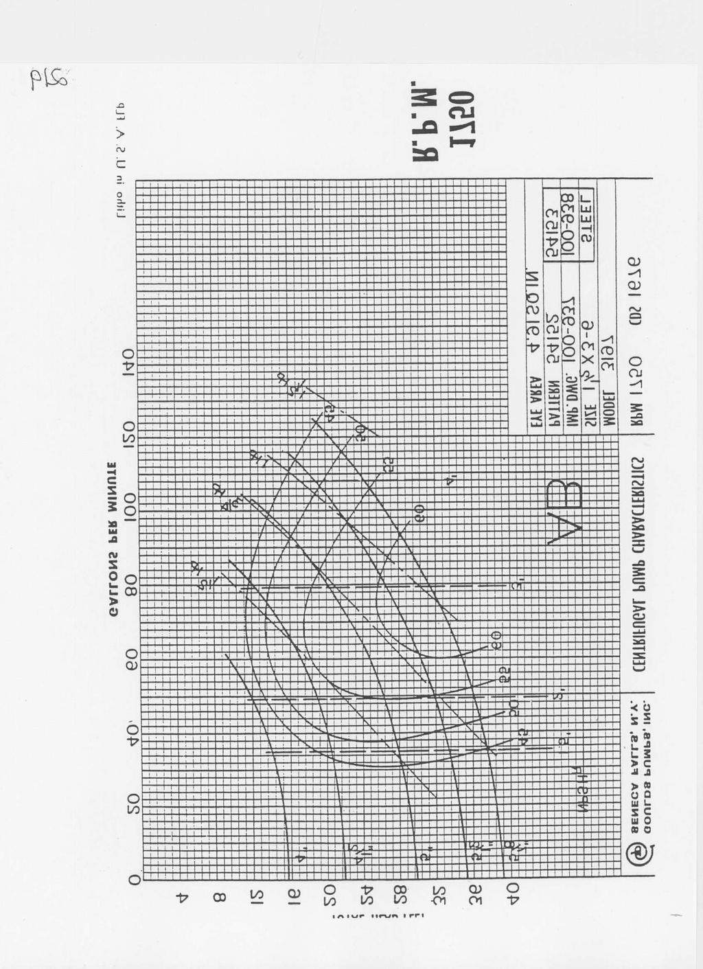
16 Appendix A V- Notch Calibration Plot *Taken from page 23 of the Gilkes equipment manual. 16

17 Venturimeter Calibration Plot *Taken from page 22 of the Gilkes equipment manual. 17
18 References 1. Perry, Robert, H., Green, Don, W., Perry s Chemical Engineers Handbook 7 th, New York, McGraw-Hill, Kroschwitz, Jacqueline, I. Eds. Howe-Grant, Mary, Eds Kirk-Othmer Encyclopedia of Chemical Technology 4 th, New York, John Wiley & Sons, 11, Pump World. Parallel Pump Operation Using Identical Pumps. April 23, 2000 Http// [Accessed June 8, 2000]. 4. Gilkes, Gilbert. Gilkes GH 75 Technical Handbook Parallel-Series Centrifugal Pump Set. Kendal, Gilbert Gilkes & Gordon LTD. 18
19 EXTRA INFORMATION NOT PLACED YET Basic explanation and operation of experimental equipment Venturimeter A Venturimeter is a device used to calculate volumetric flow. The shape of the meter creates a pressure drop between the inlet section and the narrower throat section. This pressure drop is measured with the manometer. A volumetric flow rate can be calculated in conjunction with the measured pressure drop, inlet and throat areas, and the densities of the mercury and the interested fluid. V-Notch Weir The V-notch weir is another means for calculation the flow rate. A height gauge is attached to the outlet tub, which measures the added height of the water displaced to the outlet tub. At zero flow the gauge will read zero. The flow rate can be derived from the reading of the V-notch head and the characteristic curve supplied by the manufacturer. 19
20 20
EXPERIMENT A Parallel Pump Test Rig
 KNC 1101: CHEMICAL ENGINEERING LABORATORY I LABORATORY MANUAL EXPERIMENT A Parallel Pump Test Rig Faculty of Engineering Department of Chemical Engineering & Energy Sustainability Semester 2_ 2013/2014
ECH 4224L Unit Operations Lab I Fluid Flow FLUID FLOW. Introduction. General Description
 FLUID FLOW Introduction Fluid flow is an important part of many processes, including transporting materials from one point to another, mixing of materials, and chemical reactions. In this experiment, you
FLUID FLOW. Introduction
 FLUID FLOW Introduction Fluid flow is an important part of many processes, including transporting materials from one point to another, mixing of materials, and chemical reactions. In this experiment, you
UNIVERSITY OF MINNESOTA DULUTH DEPARTMENT OF CHEMICAL ENGINEERING ChE Centrifugal Pump(Armfield)
") UNIVERSITY OF MINNESOTA DULUTH DEPARTMENT OF CHEMICAL ENGINEERING ChE 3211-4211 Centrifugal Pump(Armfield) OBJECTIVE The objective of this experiment is to investigate the operating characteristics of
UNIVERSITY OF MINNESOTA DULUTH DEPARTMENT OF CHEMICAL ENGINEERING ChE 3211-4211 Centrifugal Pump(Armfield) OBJECTIVE The objective of this experiment is to investigate the operating characteristics of
Design and Modeling of Fluid Power Systems ME 597/ABE 591
 Systems ME 597/ABE 591 Dr. Monika Ivantysynova MAHA Professor Flud Power Systems MAHA Fluid Power Research Center Purdue University Systems Dr. Monika Ivantysynova, Maha Professor Fluid Power Systems Mivantys@purdue.edu
FLUID FLOW Introduction General Description
 FLUID FLOW Introduction Fluid flow is an important part of many processes, including transporting materials from one point to another, mixing of materials, and chemical reactions. In this experiment, you
Experiment (4): Flow measurement
: Flow measurement") Introduction: The flow measuring apparatus is used to familiarize the students with typical methods of flow measurement of an incompressible fluid and, at the same time demonstrate applications of the
Introduction: The flow measuring apparatus is used to familiarize the students with typical methods of flow measurement of an incompressible fluid and, at the same time demonstrate applications of the
Heat Transfer Enhancement for Double Pipe Heat Exchanger Using Twisted Wire Brush Inserts
 Heat Transfer Enhancement for Double Pipe Heat Exchanger Using Twisted Wire Brush Inserts Deepali Gaikwad 1, Kundlik Mali 2 Assistant Professor, Department of Mechanical Engineering, Sinhgad College of
Civil Engineering Hydraulics. Radial Flow Devices
 Civil Engineering Hydraulics 2 3 Many rotary-flow devices such as centrifugal pumps and fans involve flow in the radial direction normal to the axis of rotation and are called radial- flow devices. 4 In
Estimation Procedure for Following Vapor Pressure Changes
 Estimation Procedure for Following Vapor Pressure Changes through Repeated Blending of Petroleum Stocks from Boiling Point Curves A practical method to estimate the vapor pressures of blended and reblended
Improving muffler performance using simulation-based design
 Improving muffler performance using simulation-based design Fangsen CUI 1 *; Ying WANG 2 ; Richard Chao CAI 3 1 Institute of High Performance Computing, A*STAR, Singapore 2 Jinan Dejia Machine Pte Ltd,
Effortless Water Lifting Bucket Elevator Biswa Bihari Rath 1, Nabnit Panigrahi 2
 Effortless Water Lifting Bucket Elevator Biswa Bihari Rath 1, Nabnit Panigrahi 2 1 Assistant Professor, Gandhi Institute For Technology, Bhubaneswar, Odisha India 2 Dean Research, Gandhi Institute For
Experimental Analysis on Minor Head Loss for Flow through Locally Manufactured Ball Valve for Supplying Fluid in Bangladesh
 Paper ID: FM-3 Experimental Analysis on Minor Head Loss for Flow through Locally Manufactured Ball Valve for Supplying Fluid in Bangladesh 1 2 Sadia Haque 1, M. Q. Islam 2 Department of Mechanical Engineering,
Measuring probe For ventilation and air-conditioning Model A2G-FM
 Special For ventilation and air-conditioning Model A2G-FM WIKA data sheet SP 69.10 Applications Air flow measurement in circular ventilation pipes Air flow measurement in rectangular ventilation ducts
Experiment No.3: Flow through orifice meter. Background and Theory
 Experiment No.3: Flow through orifice meter Background and Theory Flow meters are used in the industry to measure the volumetric flow rate of fluids. Differential pressure type flow meters (Head flow meters)
Test Which component has the highest Energy Density? A. Accumulator. B. Battery. C. Capacitor. D. Spring.
 Test 1 1. Which statement is True? A. Pneumatic systems are more suitable than hydraulic systems to drive powerful machines. B. Mechanical systems transfer energy for longer distances than hydraulic systems.
Lab 9 AC & Stepper Motors
 Lab 9 - AC & Stepper Motors Lab 9-1 Format Lab 9 AC & Stepper Motors This lab will be conducted during your regularly scheduled lab time in a group format. There are three lab stations with a different
NEW CAR TIPS. Teaching Guidelines
 NEW CAR TIPS Teaching Guidelines Subject: Algebra Topics: Patterns and Functions Grades: 7-12 Concepts: Independent and dependent variables Slope Direct variation (optional) Knowledge and Skills: Can relate
Al- Ameen Engg. College. Fluid Machines. Prepared by: AREEF A AP/ ME AL AMEEN ENGINEERING COLLEGE Shoranur.
 Fluid Machines Prepared by: AREEF A AP/ ME AL AMEEN ENGINEERING COLLEGE Shoranur Classification of hydraulic machines HYDROULIC MACHINES (I) Hydraulic Turbines A hydraulic machine which converts hydraulic
FLUID POWER FLUID POWER EQUIPMENT TUTORIAL HYDRAULIC AND PNEUMATIC MOTORS. This work covers part of outcome 2 of the Edexcel standard module:
 FLUID POWER FLUID POWER EQUIPMENT TUTORIAL HYDRAULIC AND PNEUMATIC MOTORS This work covers part of outcome 2 of the Edexcel standard module: UNIT 21746P APPLIED PNEUMATICS AND HYDRAULICS The material needed
TurboGen TM Gas Turbine Electrical Generation System Sample Lab Experiment Procedure
 TurboGen TM Gas Turbine Electrical Generation System Sample Lab Experiment Procedure Lab Session #1: System Overview and Operation Purpose: To gain an understanding of the TurboGen TM Gas Turbine Electrical
ESCONDIDO FIRE DEPT TRAINING MANUAL Section DRIVER OPERATOR Page 1 of 13 Pumps and Accessory Equipment Revised
 DRIVER OPERATOR Page 1 of 13 PUMPS AND ACCESSORY EQUIPMENT Pumps are designed for many different purposes. In order to understand the proper application and operation of a pump in a given situation, firefighters
An experimental analysis of two phase flow for air lift pump design
 An experimental analysis of two phase flow for air lift pump design G. K. Awari 1, P. M. Ardhapurkar 1 & D. G. Wakde 2 1 Department of Mechanical Engineering, Shri Sant Gajanan Maharaj College of Engineering,
Noise Reduction in a Reciprocating Compressor by Optimizing the Suction Muffler
 Noise Reduction in a Reciprocating Compressor by Optimizing the Suction Muffler Katakama Nagarjuna ¹ K.Sreenivas² ¹ M.tech student, ²Professor, dept of mechanical engineering kits, markapur, A.P, INDIA
Analysis of Parametric Studies on the Impact of Piston Velocity Profile On the Performance of a Single Cylinder Diesel Engine
 IOSR Journal of Mechanical and Civil Engineering (IOSR-JMCE) e-issn: 2278-1684,p-ISSN: 2320-334X, Volume 12, Issue 2 Ver. II (Mar - Apr. 2015), PP 81-85 www.iosrjournals.org Analysis of Parametric Studies
M50 L50 Series - 50Hz Metric Edition Multistage Regenerative Turbine Pumps
 Page M-M MTH PUMPS M L Series - Hz Metric Edition Multistage Regenerative Turbine Pumps Capacities to LPM Heads to 6 Meters Single or Multi-stage Units (up to stages) Vertical Close Coupled Horizontal
TUTORIAL QUESTIONS FOR THE INDUSTRIAL HYDRAULICS COURSE TEP 4205
 TUTORIAL QUESTIONS FOR THE INDUSTRIAL HYDRAULICS COURSE TEP 4205 The book for the course is Principles of Hydraulic System Design, by Peter J Chapple. Published by Coxmoor Publishing Co., UK. Available
Lab 6: Wind Turbine Generators
 Lab 6: Wind Turbine Generators Name: Pre Lab Tip speed ratio: Tip speed ratio (TSR) is defined as: Ω, where Ω=angular velocity of wind, and R=radius of rotor (blade length). If the rotational speed of
Project Manual Industrial Hydraulics
 Electric Drives and Controls Hydraulics Linear Motion and Assembly Technologies Pneumatics Service Project Manual Industrial Hydraulics RE 00845/04.07 Trainer s manual Electric Drives and Controls Hydraulics
SJSU ENGR 10 Wind Turbine Power Measurement Procedure
 SJSU ENGR 10 Wind Turbine Power Measurement Procedure In this lab, we determine the maximum electrical power that your wind turbine can generate. This involves the use of two key components: a power meter
SERVICE THE GORMAN-RUPP COMPANY P.O. Box 1217 MANSFIELD, OH FX
 GORMAN-RUPP AT YOUR SERVICE THE GORMAN-RUPP COMPANY P.O. Box MANSFIELD, OH. 90 9..0 FX 9.. EMAIL GRSALES@GORMANRUPP.COM How To Read Pump Performance Curves The subject of this bulletin covers the reading
Low-Cost Pipeline Flow Meter
 Low-Cost Pipeline Flow Meter By Tony L. Wahl 1 and Henry Magallanez 2 A new low-cost flow meter is being used to measure flows in the discharge pipelines from wells located on the Elephant Butte Irrigation
Air Flow Measurement Technologies
 Page 1/7 Typical Air Flow Measurement Applications Air Flow Control True Flow Feedback Theory of Vortex Shedding Air Flow Measurement Pitot Air Flow Measurement Thermal Air Flow Measurement Advantages
IAC-15-C4.3.1 JET INDUCER FOR A TURBO PUMP OF A LIQUID ROCKET ENGINE
 IAC-15-C4.3.1 JET INDUCER FOR A TURBO PUMP OF A LIQUID ROCKET ENGINE Martin Böhle Technical University Kaiserslautern, Germany, martin.boehle@mv.uni-kl.de Wolfgang Kitsche German Aerospace Center (DLR),
GOPALAN COLLEGE OF ENGINEERING AND MANAGEMENT Department of Civil Engineering COURSE PLAN
 Appendix - C GOPALAN COLLEGE OF ENGINEERING AND MANAGEMENT Department of Civil Engineering Academic Year: 2016-17 Semester: EVEN COURSE PLAN Semester: VI Subject Code& Name: 10CV64 & Geotechnical Engineering-II
The Discussion of this exercise covers the following points:
 Exercise 3-3 Venturi Tubes EXERCISE OBJECTIVE In this exercise, you will study the relationship between the flow rate and the pressure drop produced by a venturi tube. You will describe the behavior of
Central Station Air-Handling Units
 2008 STANDARD FOR Standard 430 Central Station Air-Handling Units ISHRAE ( INDIAN SOCIETY OF HEATING, REFRIGERATING & AIR CONDITIONING ENGINEERS 4100 N. FAIRFAX DR., STE. 200 ARLINGTON, VIRGINIA 22203
Axial Piston Variable Pump A10VO
 Electric Drives and Controls Hydraulics inear Motion and Assembly Technologies Pneumatics ervice Axial Piston Variable Pump A10VO RA 92703/11.07 1/44 Replaces: 06.07 Data sheet eries 52/53 ize 10...85
Axial Piston Fixed Pump A17FNO Series 10
 Axial Piston Fixed Pump A17FNO Series 10 RE 91510 Issue: 06.2012 Replaces: 03.2010 Size 125 Nominal pressure 250 bar Maximum pressure 300 bar For commercial vehicles Open circuit Features Fixed pump with
EXPERIMENT PITOT TUBE
 Read the following BEFORE getting started: EXPERIMENT PITOT TUBE Objectives, Pitot tube: a) Understand dynamic pressure, static pressure, and total pressure, and how they can be used to find air velocity.
Dr. Jim Henry, P.E. Professor of Engineering University of Tennessee at Chattanooga 615 McCallie Avenue Chattanooga, TN Dr.
 Aubrey Gunter Green Team - Distillation College of Engineering and Computer Science University of Tennessee at Chattanooga 615 McCallie Avenue Chattanooga, TN 37421 To: Dr. Jim Henry, P.E. Professor of
MAGNETIC FORCE ON A CURRENT-CARRYING WIRE
 MAGNETIC FORCE ON A CURRENT-CARRYING WIRE Pre-Lab Questions Page 1. What is the SI unit for Magnetic Field? Name: Class: Roster Number: Instructor: 2. The magnetic field on a wire is 12.0 x 10 5 Gausses,
44 (0) E:
 E:") FluidFlow Equipment Sizing Handbook Flite Software 2018 Flite Software N.I. Ltd, Block E, Balliniska Business Park, Springtown Rd, Derry, BT48 0LY, N. Ireland. T: 44 (0) 2871 279227 E: sales@fluidflowinfo.com
FluidFlow Equipment Sizing Handbook Flite Software 2018 Flite Software N.I. Ltd, Block E, Balliniska Business Park, Springtown Rd, Derry, BT48 0LY, N. Ireland. T: 44 (0) 2871 279227 E: sales@fluidflowinfo.com
Pumping Station. Marisa Handajani
 Pumping Station Marisa Handajani Function To lift or to elevate the liquid from a lower elevation to an adequate height at which it can flow by gravity or overcome the hydrostatic head Applications: 1.
Regenerative Turbine Pumps
 Bulletin M M Series Regenerative Turbine Pumps Capacities to 8 GPM Heads to Feet MTH M Series Vertical base mount and horizontal pedestal mounted multi-stage regenerative turbine pumps represent the most
Experimental Study Of The Oil Injection Screw Air Compressor
 Purdue University Purdue e-pubs International Compressor Engineering Conference School of Mechanical Engineering 2002 Experimental Study Of The Oil Injection Screw Air Compressor Z. Zhang Y. Tan G. Shi
FIXED CONE VALVE. The flow is guided by the inner vanes, in order to decrease the vortex and the vibration;
 BEI JI NG JOI NTFLOW SYSTEM CO. FI XEDCONEVALVE The Fixed cone Valve is typically operated by a manual, electric or hydraulic actuator mounted above the bevel gear. The bevel gear transmits torque to the
Figure 1: Forces Are Equal When Both Their Magnitudes and Directions Are the Same
 Moving and Maneuvering 1 Cornerstone Electronics Technology and Robotics III (Notes primarily from Underwater Robotics Science Design and Fabrication, an excellent book for the design, fabrication, and
DESIGN OF THROTTLE BODY: A COMPARATIVE STUDY OF DIFFERENT SHAFT PROFILES USING CFD ANALYSIS
 Int. J. Chem. Sci.: 14(S2), 2016, 681-686 ISSN 0972-768X www.sadgurupublications.com DESIGN OF TROTTLE BODY: A COMARATIVE STUDY OF DIFFERENT SAFT ROFILES USING CFD ANALYSIS M. BALAJI *, K. AMAL SATEES,
11/12/2017 Erwin H. Doorenspleet
 Slide 1 Slide 2 Slide 3 Introduction: Density Measurement Additionally to mass flow multi-variable Coriolis mass flow meters also determine temperature and density Precise density measurement performance
SUPERCHARGER AND TURBOCHARGER
 SUPERCHARGER AND TURBOCHARGER 1 Turbocharger and supercharger 2 To increase the output of any engine more fuel can be burned and make bigger explosion in every cycle. i. One way to add power is to build
Variable Vane Pump, Direct Controlled PV7...A Series 1X / 2X
 Variable Vane Pump, Direct Controlled PV7...A Series 1X / X RE 1 Issue: 1.13 Replaces: 8.8 Sizes 1 to Maximum pressure 1 bar Displacement volume 1 to cm 3 Features Very short control times Low noise Mounting
Waterous S100 Single Stage Pump
 The S100 Series end suction fire pump provides versatility in a smaller package. With a capacity of 2000 GPM (7570 L/min), the S100 Features a dynamic yet compact design, incorporating a ductile iron body
Simple Finite Heat Release Model (SI Engine)
") Simple Finite Heat Release Model (SI Engine) Introduction In the following, a finite burn duration is taken into account, in which combustion occurs at θ soc (Start Of Combustion), and continues until
Simple Finite Heat Release Model (SI Engine) Introduction In the following, a finite burn duration is taken into account, in which combustion occurs at θ soc (Start Of Combustion), and continues until
SERVICE & OPERATING MANUAL
 SERVICE & OPERATING MANUAL 8-4 Mud Cleaner (03-00-060) INTRODUCTION The Triflo 8-4 Mud Cleaner is capable of processing up to 520 gallons per minute and can get do to cut point of approximately 35 microns.
Series
 MTH PUMPS 15 25 26 17 27 Series Flexible Coupled Capacities to 15 GPM Heads to 115 Feet Low NPSH Requirements Page 1-19 15 17 25 26 27 LIMITATIONS Discharge Pressure Seal Pressure* Suction Pressure (Min.)
PUMP HEART OF PLUMBING SYSTEM V.SRINIVAS
 PUMP HEART OF PLUMBING SYSTEM V.SRINIVAS Pump is the most important element in the Plumbing system and may be considered as its Heart. Majority of Energy in Plumbing systems is consumed by Pumps. It is
Comparison of Swirl, Turbulence Generating Devices in Compression ignition Engine
 Available online atwww.scholarsresearchlibrary.com Archives of Applied Science Research, 2016, 8 (7):31-40 (http://scholarsresearchlibrary.com/archive.html) ISSN 0975-508X CODEN (USA) AASRC9 Comparison
Hydraulics Guide. Table 1: Conveyance Factors (English Units)... 7 Table 2: Conveyance Factors (Metric Units)... 8
... 7 Table 2: Conveyance Factors (Metric Units)... 8") Table of Contents 1.1 Index of Tables... 1 1.2 Index of Figures... 1 1.3 Overview of Hydraulic Considerations... 2 1.4 Discharge Curves... 2 1.5 Conveyance Method... 5 1.6 Flow Velocity Considerations...
Table of Contents 1.1 Index of Tables... 1 1.2 Index of Figures... 1 1.3 Overview of Hydraulic Considerations... 2 1.4 Discharge Curves... 2 1.5 Conveyance Method... 5 1.6 Flow Velocity Considerations...
CONSTRUCTION AND ANALYSIS OF TUBE IN TUBE TYPE HEAT EXCHANGER
 CONSTRUCTION AND ANALYSIS OF TUBE IN TUBE TYPE HEAT EXCHANGER N. S. Panchal 1, O. V. Pathak 2, G. P. Chaudhari 3, A. H. Paulkar 4, Asst. Prof. B. M. Dusane 5 Department of mechanical engineering, Sandip
Appendix A: Motion Control Theory
 Appendix A: Motion Control Theory Objectives The objectives for this appendix are as follows: Learn about valve step response. Show examples and terminology related to valve and system damping. Gain an
Study on Flow Characteristic of Gear Pumps by Gear Tooth Shapes
 Journal of Applied Science and Engineering, Vol. 20, No. 3, pp. 367 372 (2017) DOI: 10.6180/jase.2017.20.3.11 Study on Flow Characteristic of Gear Pumps by Gear Tooth Shapes Wen Wang 1, Yan-Mei Yin 1,
ME 466 PERFORMANCE OF ROAD VEHICLES 2016 Spring Homework 3 Assigned on Due date:
 PROBLEM 1 For the vehicle with the attached specifications and road test results a) Draw the tractive effort [N] versus velocity [kph] for each gear on the same plot. b) Draw the variation of total resistance
Hot Air Engine, Type Stirling
 UMEÅ UNIVERSITY 2013-11-20 Department of Physics Leif Hassmyr Updated versions 2017-10-30: Joakim Ekspong Hot Air Engine, Type Stirling 1 Hot Air Engine, type Stirling - contents The object with this experiment
DESIGN AND ANALYSIS OF UNDERTRAY DIFFUSER FOR A FORMULA STYLE RACECAR
 DESIGN AND ANALYSIS OF UNDERTRAY DIFFUSER FOR A FORMULA STYLE RACECAR Ali Asgar S. Khokhar 1, Suhas S. Shirolkar 2 1 Graduate in Mechanical Engineering, KJ Somaiya College of Engineering, Mumbai, India.
Technology of Machine Tools
 PowerPoint to accompany Technology of Machine Tools 6 th Edition Krar Gill Smid Gear Cutting Unit 70 Copyright The McGraw-Hill Companies, Inc. Permission required for reproduction or display. 70-2 Objectives
Recommendations for AASHTO Superelevation Design
 Recommendations for AASHTO Superelevation Design September, 2003 Prepared by: Design Quality Assurance Bureau NYSDOT TABLE OF CONTENTS Contents Page INTRODUCTION...1 OVERVIEW AND COMPARISON...1 Fundamentals...1
Storvik HAL Compactor
 Storvik HAL Compactor Gunnar T. Gravem 1, Amund Bjerkholt 2, Dag Herman Andersen 3 1. Position, Senior Vice President, Storvik AS, Sunndalsoera, Norway 2. Position, Managing Director, Heggset Engineering
DESIGN OF COMPRESSED NATURAL GAS MIXER USING COMPUTATIONAL FLUID DYNAMICS. D. Ramasamy, S. Mahendran, K. Kadirgama and M. M. Noor
 National Conference in Mechanical Engineering Research and Postgraduate Students (1 st NCMER 2010) 26-27 MAY 2010, FKM Conference Hall, UMP, Kuantan, Pahang, Malaysia; pp. 614-620 ISBN: 978-967-5080-9501
Model 133 Models 134 & 135 AURORA 130 SERIES SINGLE STAGE TURBINE TYPE PUMPS
 Model Models 4 & AURORA 0 SERIES SINGLE STAGE TURBINE TYPE PUMPS WWW.AURORAPUMP.COM AURORA 0 SERIES Single Stage Turbine Type Pumps Capacities to 0 G.P.M. Heads to 700 Ft. Temperatures to F A Pioneer in
Multilayer Energy Dissipating Inlet Column in Center-Feed Clarifiers 1
 Multilayer Energy Dissipating Inlet Column in Center-Feed Clarifiers 1 References 6,276,537 08/21/2001 Esler et al 210/519 6,800,209 10/05/2004 Wright 210/801 Field of Invention Clarifiers are tanks where
M50 L50 Series Multistage Regenerative Turbine Pumps
 Page M- MTH PUMPS M L Series Multistage Regenerative Turbine Pumps Capacities to 4 GPM Heads to Feet Single or Multi-stage Units (up to stages) Vertical Close Coupled Horizontal Close Coupled Horizontal
FLUID POWER TUTORIAL HYDRAULIC PUMPS APPLIED PNEUMATICS AND HYDRAULICS H1
 FLUID POWER TUTORIAL HYDRAULIC PUMPS This work covers outcome 2 of the Edexcel standard module: APPLIED PNEUMATICS AND HYDRAULICS H1 The material needed for outcome 2 is very extensive so the tutorial
The Mechanics of Tractor Implement Performance
 The Mechanics of Tractor Implement Performance Theory and Worked Examples R.H. Macmillan CHAPTER 2 TRACTOR MECHANICS Printed from: http://www.eprints.unimelb.edu.au CONTENTS 2.1 INTRODUCTION 2.1 2.2 IDEAL
Determination of power loss of combine harvester travel gear
 Agronomy Research 13(1), 5 3, 015 Determination of power loss of combine harvester travel gear L. Beneš *, P. Heřmánek and P. Novák Czech University of Life Sciences Prague, Faculty of Engineering, Department
Increasing Low Speed Engine Response of a Downsized CI Engine Equipped with a Twin-Entry Turbocharger
 Increasing Low Speed Engine Response of a Downsized CI Engine Equipped with a Twin-Entry Turbocharger A. Kusztelan, Y. F. Yao, D. Marchant and Y. Wang Benefits of a Turbocharger Increases the volumetric
Component and System Level Modeling of a Two-Phase Cryogenic Propulsion System for Aerospace Applications
 Component and System Level Modeling of a Two-Phase Cryogenic Propulsion System for Aerospace Applications J. LoRusso, B. Kalina, M. Van Benschoten, Roush Industries GT Users Conference November 9, 2015
TurboGen TM Gas Turbine Electrical Generation System Sample Lab Experiment Procedure
 TurboGen TM Gas Turbine Electrical Generation System Sample Lab Experiment Procedure Lab Session #1: System Overview and Operation Purpose: To gain an understanding of the TurboGen TM Gas Turbine Electrical
Programme area 4a. Fluid Energy Machines
 Programme area 4a Fluid Energy 136 Contents: Fundamentals of Fluid Mechanics 138 Thermodynamics 140 Mechanics / Other 142 Power Engines Hydroturbines Pelton...143 Francis...144 others...145 Steam Turbines...146
Axial Piston Fixed Motor A2FNM for Fan Drives and Flywheel Mass
 Electric Drives and Controls Hydraulics Linear Motion and ssembly Technologies Pneumatics Service xial Piston Fixed Motor 2FNM for Fan Drives and Flywheel Mass RE 91007/02.11 1/16 Data sheet Series 61
Projekthandbuch. Project Manual Industriehydraulik. Industrial Hydraulics RE 00846/ Trainee's manual. Schülerhandbuch
 Electric Drives and Controls Hydraulics Linear Motion and Assembly Technologies Pneumatics Service Projekthandbuch Project Manual Industriehydraulik Industrial Hydraulics RE 00846/04.07 Schülerhandbuch
SWIRL MEASURING EQUIPMENT FOR DIRECT INJECTION DIESEL ENGINE
 SWIRL MEASURING EQUIPMENT FOR DIRECT INJECTION DIESEL ENGINE G.S.Gosavi 1, R.B.Solankar 2, A.R.Kori 3, R.B.Chavan 4, S.P.Shinde 5 1,2,3,4,5 Mechanical Engineering Department, Shivaji University, (India)
ATZAF DOUBLE INLET CENTRIFUGAL FANS WITH AIRFOIL BACKWARD CURVED BLADES
 ATZAF DOUBLE INLET CENTRIFUGAL FANS WITH AIRFOIL BACKWARD CURVED BLADES COMEFRI USA: Manufacturing and Warehouse facilities in Hopkinsville, KY. Total facility: 125,000 sq.ft. Producing centrifugal fans
ENERGY EXTRACTION FROM CONVENTIONAL BRAKING SYSTEM OF AUTOMOBILE
 Proceedings of the International Conference on Mechanical Engineering 2009 (ICME2009) 26-28 December 2009, Dhaka, Bangladesh ICME09- ENERGY EXTRACTION FROM CONVENTIONAL BRAKING SYSTEM OF AUTOMOBILE Aktaruzzaman
Constructive Influences of the Energy Recovery System in the Vehicle Dampers
 Constructive Influences of the Energy Recovery System in the Vehicle Dampers Vlad Serbanescu, Horia Abaitancei, Gheorghe-Alexandru Radu, Sebastian Radu Transilvania University Brasov B-dul Eroilor nr.
FEASIBILITY STYDY OF CHAIN DRIVE IN WATER HYDRAULIC ROTARY JOINT
 FEASIBILITY STYDY OF CHAIN DRIVE IN WATER HYDRAULIC ROTARY JOINT Antti MAKELA, Jouni MATTILA, Mikko SIUKO, Matti VILENIUS Institute of Hydraulics and Automation, Tampere University of Technology P.O.Box
COST ANALYSIS FOR BRIDGE AND CULVERT. Essam A. Mostafa
 Seventh International Water Technology Conference IWTC7 Cairo 1-3 April 2003 357 COST ANALYSIS FOR BRIDGE AND CULVERT Essam A. Mostafa Associate Professor, Irrigation & Hydraulics Department, Faculty of
Structural Analysis Of Reciprocating Compressor Manifold
 Purdue University Purdue e-pubs International Compressor Engineering Conference School of Mechanical Engineering 2016 Structural Analysis Of Reciprocating Compressor Manifold Marcos Giovani Dropa Bortoli
Applied Fluid Mechanics
 Applied Fluid Mechanics 1. The Nature of Fluid and the Study of Fluid Mechanics 2. Viscosity of Fluid 3. Pressure Measurement 4. Forces Due to Static Fluid 5. Buoyancy and Stability 6. Flow of Fluid and
Multiple Pump Systems
 Industrial Maintenance Pumps Training System Multiple Pump Systems Job Sheets - Courseware Sample 37895-F0 Order no.: 37895-30 First Edition Revision level: 08/2015 By the staff of Festo Didactic Festo
Flygt N-Pumps 3085, 3102 & 3127
 Flygt N-Pumps 3085, 3102 & 3127 For reliable and efficient wastewater handling The ConCepT Flygt N-Pump series Reduced pumping efficiency, high energy and maintenance costs shouldn t be a fact of life
Theory of Machines II EngM323 Laboratory User's manual Version I
 Theory of Machines II EngM323 Laboratory User's manual Version I Table of Contents Experiment /Test No.(1)... 2 Experiment /Test No.(2)... 6 Experiment /Test No.(3)... 12 EngM323 Theory of Machines II
AXIAL PISTON PUMPS SHPV SECTIONAL VIEW
 AXIAL PISTON PUMPS SHPV SECTIONAL VIEW 2 SYSTEM CIRCUIT PUMP AND MOTOR CIRCUIT working loop (high pressure) working loop (low pressure) control fluid suction line case drain fluid Above figure shows schematically
Perodua Myvi engine fuel consumption map and fuel economy vehicle simulation on the drive cycles based on Malaysian roads
 Perodua Myvi engine fuel consumption map and fuel economy vehicle simulation on the drive cycles based on Malaysian roads Muhammad Iftishah Ramdan 1,* 1 School of Mechanical Engineering, Universiti Sains
test with confidence HV Series TM Test Systems Hydraulic Vibration
 test with confidence HV Series TM Test Systems Hydraulic Vibration Experience. Technology. Value. The Difference. HV Series TM. The Difference. Our philosophy is simple. Provide a system designed for optimum
2.6. Air Flow Control Valve Type PRD
 2.6. Air Flow Control Valve Type PRD Page 1/10 Air Flow Control Valve, Type PRD Page 2/10 Air Flow Control Valve Type PRD Description and Design The PRD remains the air valve of choice for critical heating,
Pump Control Ball Valve for Energy Savings
 VM PCBVES/WP White Paper Pump Control Ball Valve for Energy Savings Table of Contents Introduction............................... Pump Control Valves........................ Headloss..................................
Nick Desiderio, April15, 2014
 Determination of Saybolt, Kinematic, and Shear Viscosity for a Variety of Liquids: Baby Oil, Biodiesel, Diesel, Jet Fuel, Yogurt, Ketchup, Glycerin, and Shampoo Nick Desiderio, npd5050@psu.edu, April15,
three different ways, so it is important to be aware of how flow is to be specified
 Flow-control valves Flow-control valves include simple s to sophisticated closed-loop electrohydraulic valves that automatically adjust to variations in pressure and temperature. The purpose of flow control
ISSN (PRINT): ,(ONLINE): ,VOLUME-2,ISSUE-4,2016 1
: ,(ONLINE): ,VOLUME-2,ISSUE-4,2016 1") A STUDY ON THE ACOUSTIC PERFORMANCE OF A REACTIVE MUFFLER Shemin Thomas Varkey 1, Lalu P. P 2, K. Balakrishnan 3 1 Post Graduate Student, Government Engineering College, Thrissur, 2 Assistant Professor,
A STUDY ON THE ACOUSTIC PERFORMANCE OF A REACTIVE MUFFLER Shemin Thomas Varkey 1, Lalu P. P 2, K. Balakrishnan 3 1 Post Graduate Student, Government Engineering College, Thrissur, 2 Assistant Professor,