PRINCIPLES OF OPERATION
|
|
|
- George Dawson
- 6 years ago
- Views:
Transcription
1 "Magnetic Drive" refers to the coupling between the wet end of the pump and the motor. In "direct drive" pumps, the impeller of the pump is attached to the shaft of the motor, and this design depends on the shaft seal to contain the chemical. In a magnetic drive pump, the wet end and motor are two separate contained parts, connected by only a motor bracket. At the end of the motor shaft, a drive magnet is attached, and as the drive magnet rotates around the rear housing, the impeller, which is fixed upon another magnet, spins in synchronization. It is the attraction of the drive magnet and the impeller magnet that allows the full torque of the motor to be passed onto the pump. As the shaft of the motor does not extend into the interior of the pump, there is no need for a shaft seal, and without a shaft seal, the danger of leakage commonly associated with a shaft seal is eliminated. Furthermore, the maintenance cost is reduced because no time or money is spent on maintaining the shaft seal. For a pump that eliminates the problems and costs associated with mechanical seals, the Magnetic Drive Pump has no equal. Section B -- Pump Application Data B-4B Magnetic Drive Pumps INTRODUCTION Environmental concerns and recurring mechanical seal problems have created a need for sealless pumps in the chemical and petrochemical industries. In some cases, more stringent regulations by the EPA, OSHA and local agencies are mandating the use of sealless pumps. One type of sealless pump is the magnetic drive pump which uses a permanent magnetic coupling to transmit torque to the impeller without the need for a mechanical seal for packing. PRINCIPLES OF OPERATION Magnetic drive pumps use a standard electric motor to drive a set of permanent magnets that are mounted on a carrier or drive assembly located outside of the containment shell. The drive magnet assembly is mounted on a second shaft which is driven by a standard motor. The external rotating magnetic field drives the inner rotor. The coaxial synchronous torque coupling consists of two rings of permanent magnets as shown in Fig. 1. A magnetic force field is established between the north and south pole magnets in the drive and driven assemblies. This provides the no slip or synchronous capability of the torque coupling. The magnetic

2 field is shown as dashed lines and shaded areas in Fig. 3.

3 Two Types of Magnetic Drive Pump A. Rotating Driven Shaft This type of design typically uses metal components and is best suited for heavy duty applications. The metallic construction offers the best strength, temperature and pressure capability required for heavy duty applications. Corrosion resistant high alloy materials such as 316SS, Hastelloy, and Alloy 20 are offered. The rotating shaft does, however, increase the number of parts required and thus increases the complexity and cost of the pump. This type of design typically uses a pressurized recirculation circuit, which helps prevent vaporization of liquid required for process lubricated bearings. (Refer to Model 3296, Section CHEM-3A). B. Stationary Shaft This type of design typically uses non-metallic components such as ceramics and plastics. It is best suited for light to medium duty applications. The stationary shaft design significantly reduces the number of parts required, simplifying maintenance and reducing cost. Corrosion resistant materials such as silicon carbide ceramics and fluoropolymer plastics (Teflon, Tefzel, etc.) provide excellent range of application. The use of plastics materials does, however, limit the temperature range of these designs to 200 o F to 250 o F. (Refer to Model 3298, Section CHEM- 3C). Containment Shell Designs The containment shell is the pressure containing barrier which is fitted between the drive and the driven magnet assembly. It must contain full working pressure of the pump, since it isolates the pumped liquid from the atmosphere. One-piece formed shells offer the best reliability, eliminating welds used for two-piece shells. Since the torque coupling magnetic force field must pass through the shell, it must be made of a nonmagnetic material. Non-magnetic metals such as Hastelloy and 316SS are typical choices for the containment shell. The motion of the magnets past an electrically conductive containment shell produces eddy currents, which
4 generate heat and must be removed by a process fluid recirculation circuit. The eddy currents also create a horsepower loss, which reduces the efficiency of the pump. Metals with low electrical conductivity have lower eddy current losses, providing superior pump efficiency. Hastelloy has a relatively low electrical conductivity and good corrosion resistance, thus is an excellent choice for metal containment shells. Electrically non-conductive materials such as plastic and ceramics are also good choices for containment shells, since the eddy current losses are totally eliminated. This results in pump efficiencies equal to conventionally sealed pumps. Plastic containment shells are generally limited to lower pressures and temperatures due to the limited strength of plastics. Sleeve and Thrust Bearings Magnetic drive pumps utilize process lubricated bearings to support the inner drive rotor. These bearings are subject to the corrosive nature of the liquids being pumped, thus need to be made from corrosion resistant materials. Two commonly used materials are hard carbon and silicon carbide (SIC). Pure sintered SIC is superior to reaction bonded SIC, since reaction bonded SIC has free silicon left in the matrix, resulting in lower chemical resistance and lower strength. Hard carbon against silicon carbide offers excellent service life for many chemical applications and also offers the advantage of short term operation in marginal lubrication conditions. Silicon carbide against silicon carbide offers excellent service life for nearly all chemical applications. Its hardness, high thermal conductivity, and strength make it an excellent bearing material. Silicon carbide must be handled carefully to prevent chipping. Silicon carbide against silicon carbide has very limited capability in marginal lubrication conditions. Recirculation Circuit All magnetic drive pumps circulate some of the process fluid to lubricate and cool the bearings supporting the inner rotor. Magnetic drive pumps with metal containment shells, also require a circulation of some process fluid through the containment shell to remove heat generated by eddy currents. For pumps with metal containment shells, the fluid recirculation path must be carefully engineered to prevent vaporization of the process liquid necessary to lubricate the bearings. A pressurized circuit as shown in Fig. 4 offers excellent reliability for pumps with metal containment shells. Magnetic drive pumps with electrically non-conductive containment shells, such as plastic or ceramic have no heat generated by eddy currents. Since no heat is required to be removed from the containment shell, a much simpler recirculation circuit can be used.

5 For liquids near vaporization, a calculation must be made to ensure the process fluid does not vaporize at the bearings. This calculation includes the effects of process fluid specific heat, vapor pressure, drive losses, recirculation flow, etc. This calculation procedure can be found in the GOULDS PUMPS HANDBOOK FOR MAGNETIC DRIVE PUMPS. An external cooling system can be added to the recirculation circuit to prevent vaporization. Fail Safe Devices DESCRIPTION Condition monitoring of the pump is a "key objective" and provides the user with an assurance of safety and reliability. System and pump malfunctions can result from the following: No-flow condition through the pump Dry running as a result of plugged liquid circulation paths in the pump bearing and magnets assembly section Cavitation due to insufficient NPSHA Uncoupling of the magnetic drive due to overload Temperature and pressure transients in the system "Flashing" in the pump liquid circulation paths due to pressure and temperature transients. These malfunctions can contribute to: Overheating of the drive and driven magnet assemblies Overload of drive motor and drive magnetic assembly Extreme pump bearing load conditions Damage to pump due to extremes in temperatures and pressures due to transients that exceed normal design.


6 Various fail safe devices are available with the pump to control malfunctions and provide safety and reliability including: thermocouple / controller low amp relay liquid leak detector power monitor Section B -- Field Testing Methods A. Determination of total head The total head of a pump can be determined by gauge readings as illustrated in Fig. 1. Fig 1 Determination of Total Head from Guage Readings Negative Suction Pressure: TDH = Discharge gauge reading converted to feet of liquid + vacuum gauge reading converted to feet of liquid + distance between point of attachment of vacuum gauge and the centerline of the discharge Positive Suction Pressure: or TDH=Discharge gauge reading converted to feet of liquid-pressure gauge reading in suction line converted to ft. of liquid + distance between center of discharge and suction gauges, h, in feet


7 In using gauges when the pressure is positive or above atmos-pheric pressure, any air in the gauge line should be vented off by loosening the gauge until liquid appears. This assures that the entire gauge line is filled with liquid and thus the gauge will read the pressure at the elevation of the centerline of the gauge. However, the gauge line will be empty of liquid when measuring vacuum and the gauge will read the vacuum at the elevation of the point of attachment of the gauge line to the pipe line. These assumptions are reflected in the above definitions. The final term in the above definitions accounts for a difference in size between the suction and discharge lines. The discharge line is normally smaller than the suction line and thus the dis-charge velocity is higher. A higher velocity results in a lower pressure since the sum of the pressure head and velocity head in any flowing liquid remains constant. Thus, when the suction and discharge line sizes at the gauge attachment points are different, the resulting difference in velocity head must be in-cluded in the total head calculation. Manometers can also be used to measure pressure. The liquid used in a manometer is normally water or mercury, but any liquid of known specific gravity can be used. Manometers are extremely accurate for determining low pressures or vacuums and no calibration is needed. They are also easily fabricated in the field to suit any particular application. Figs. 2 & 3 illustrate typical manometer set ups. Fig. 2 Manometer Indicating Vacuum


8 Fig. 3 Manometer Indicating Pressure B. Measurement of capacity a.) Magnetic Flow Meter A calibrated magnetic flow meter is an accurate means of measuring flow in a pumping system. However, due to the ex-pense involved, magnetic flow meters are only practical in small factory test loops and in certain process pumping systems where flow is critical. b.) Volumetric measurement Pump capacity can be determined by weighing the liquid pumped or measuring its volume in a calibrated vessel. This is often practical when pumping into an accurately measured reservoir or tank, or when it is possible to use small containers which can be accurately weighed. These methods, however, are normally suited only to relatively small capacity systems. c.) Venturi meter A venturi meter consists of a converging section, a short con-stricting throat section and then a diverging section. The object is to accelerate the fluid and temporarily lower its static pressure. The flow is then a function of the pressure differential between the full diameter line and the throat. Fig. 4 shows the general shape and flow equation. The meter coefficient is determined by actual calibration by the manufacturer and when properly installed the Venturi meter is accurate to within plus or minus 1%.
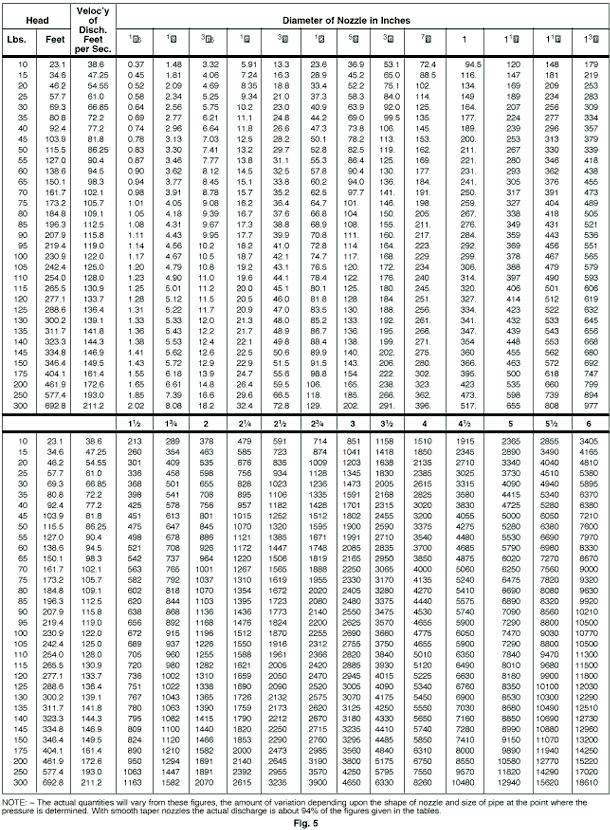
 Nozzle A nozzle is simply the converging portion of a venturi tube with")

9 Fig. 4 Venturi Meter d.) Nozzle A nozzle is simply the converging portion of a venturi tube with the liquid exiting to the atmosphere. Therefore, the same formula can be used with the differential head equal to the gauge read-ing ahead of the nozzle. Fig. 5 lists theoretical nozzle discharge flows.
10

 Weir A weir is particularly well suited to measuring flows in open conduits and can be adapted to extremely large capacity systems. For best accuracy, a weir should be calibrated in place.")
11 e.) Orifice An orifice is a thin plate containing an opening of specific shape and dimensions. The plate is installed in a pipe and the flow is a function of the pressure upstream of the orifice. There are numerous types of orifices available and their descriptions and applications are covered in the Hydraulic Institute Standards and the ASME Fluid Meters Report. Orifices are not recommended for permanent installations due to the inherent high head loss across the plate. Fig. 6 Weirs f.) Weir A weir is particularly well suited to measuring flows in open conduits and can be adapted to extremely large capacity systems. For best accuracy, a weir should be calibrated in place. However, when this is impractical, there are formulas which can be used for the various weir configurations. The most common types are the rectangular contracted weir and the 90 V-notch weir. These are shown in Fig. 6 with the applicable flow formulas. g.) Pitot tube A pilot tube measures fluid velocity. A small tube placed in the flow stream gives two pressure readings: one receiving the full impact of the flowing stream reads static head + velocity head, and the other reads the static head only (Fig. 7). The difference between the two readings is the velocity head. The velocity and the flow are then determined from the following well known formulas. Capacity = Area x Average Velocity Since the velocity varies across the pipe, it is necessary to obtain a velocity profile to determine the average velocity.


12 This involves some error, but when properly applied a calibrated pilot tube is within plus or minus 2% accuracy. Fig. 7 Pitot Tube Section B -- Vibration Analysis Vibration analysis equipment enables you to tell when "normal" vibration becomes "problem" vibration or exceeds acceptable levels. It may also allow you to determine the source and cause of the vibration, thus becoming an effective preventive maintenance and troubleshooting aid. A vibration analyser measures the amplitude, frequency and phase of vibration. Also when vibration occurs at several frequencies, it separates one frequency from another so that each individual vibra-tion characteristic can be measured. The vibration pickup senses the velocity of the vibration and converts it into an electrical signal. The analyzer receives this signal, converting it to the corresponding amplitude and frequency. The amplitude is measured in terms of peak-to-peak displacement in mils (1 mil =.001") and is indicated on the amplitude meter. Some instruments are equipped with a frequency meter which gives a direct readout of the predominant frequency of the vibration. Other instruments have tunable filters which allow scanning the frequency scale and reading amplitude at any particular frequency, all others being filtered out. A strob light is used to determine the phase of vibration. It can be made to flash at the frequency of the vibration present or at any arbitrary frequency set on an internal oscillator. A reference mark on a rotating part viewed under the strob light flashing at the vibration frequency may appear as a single frozen (or rotat-ing) mark, or as several frozen (or rotating) marks. The number of marks viewed is useful in determining
13 the source of the vibration. The location of the mark or marks is used in balancing rotating parts. The first step in vibration analysis is to determine the severity of the vibration, then, if the vibration is serious, a complete set of vibration readings should be taken before attempting to analyze the cause. Fig. 1 is the typical guide for end suction stock pumps as published by the Hydraulic Institute. The amplitudes shown are the overall RMS obtained without filtering to specific frequencies. Amplitudes at specific frequencies, such as vane pass frequency with multi-vane impellers, should be less than 75% of the unfiltered amplitudes allowed in Fig. 1 at the operating RPM. For other pumps, refer to Hydraulic Institute standards or pump manufacturer. Fig. 1 Acceptable Field Vibration Limits for Horizontal Pumps - Clear Liquid (Rigid Structures) Severity of vibration is a function of amplitude and pump speed; however, it should be noted that a change in severity over a period of time is usually a
14 warning of impending failure. This change is often more important than vibration in the "slightly rough" or "rough" ranges which does not change with time. Complete pump vibration analysis requires taking vibration readings at each bearing in three planes (horizontal, vertical and axial). Readings at the pump suction and discharge flanges may also be useful in some cases. After all data has been tabulated, it can be analyzed to determine the most likely cause or causes of vibration and the identifying characteristics of each. By analyzing the tabulated vibration data one or several causes may be found. Each must be checked, starting with the most likely cause or easiest to check. For example, assume the axial vibration is 50% or more of the radial vibration and the predominant frequency is the same as the RPM of the pump. The chart indicates probable misalignment or bent shaft. Coupling misalignment is probably the most common single cause of pump vibration and is one of the easiest to check. If after checking, the alignment proves to be good, then inspect for flange loading. Finally, check for a bent shaft. Cavitation in a pump can cause serious vibration. Vibration at random frequencies can also be caused by hydraulic disturbances in poorly designed suction or discharge systems. The use of vibration equipment in preventative maintenance involves keeping a vibration history on individual pieces of equipment in a plant. A form similar to that shown in Fig 3 can be used to record the vibration data on a periodic routine basis. Abrupt changes are a sign of impending failure. A gradual increase in vibration can also be detected and corrective measures can be taken before it reaches a dangerous level.

15 Fig. 3 Vibration Identification Chart


16 Fig. 4 Vibration Data Sheet Section B -- Pump Application Data 1. DATUM OR GRADE - The elevation of the surface from which the pump is supported. 2. STATIC LIQUID LEVEL - The vertical distance from grade to the liquid level when no liquid is being drawn from the well or source. 3. DRAWDOWN - The distance between the static liquid level and the liquid level when pumping at required capacity. 4. PUMPING LIQUID LEVEL - The vertical distance from grade to liquid level when pumping at rated cap-acity. Pumping liquid level equals static water level plus drawdown. 5. SETTING - The distance from grade to the top of the pump bowl assembly. 6. TPL (TOTAL PUMP LENGTH) - The distance from grade to lowest point of pump. 7. RATED PUMP HEAD - Lift below discharge plus head above discharge

17 plus friction losses in discharge line. This is the head for which the customer is responsible and does not include any losses within the pump. 8. COLUMN AND DISCHARGE HEAD FRICTION LOSS - Head loss in the pump due to friction in the column assembly and discharge head. Friction loss is measured in feet and is dependent upon column size, shaft size, setting, and discharge head size. Values given in appropriate charts in Data Section. 9. BOWL HEAD - Total head which the pump bowl assembly will deliver at the rated capacity. This is curve performance. 10. BOWL EFFICIENCY- The efficiency of the bowl unit only. This value is read directly from the performance curve.
18 11. BOWL HORSEPOWER- The horsepower - required by the bowls only to deliver a specified capacity against bowl head. 12. TOTAL PUMP HEAD - Rated pump head plus column and discharge head loss. Note: This is new or final bowl head. 13. SHAFT FRICTION LOSS - The horsepower required to turn the lineshaft in the bearings. These values are given in appropriate table in Data Section. 14. PUMP BRAKE HORSEPOWER - Sum of 'bowl horsepower plus shaft loss (and the driver thrust bearing loss under certain conditions). 15. TOTAL PUMP EFFICIENCY (WATER TO WATER) -The efficiency of the complete pump less.the driver, with all pump losses taken into account. 16. OVERALL EFFICIENCY (WIRE TO WATER)-The efficiency of the pump and motor complete. Overall efficiency = total pump efficiency X motor efficiency. 17. SUBMERGENCE-Distance from liquid level to suction bell. Section B -- Vertical Turbine Pumps Turbine Nomenclature Vertical Turbine Pumps Calculating Axial Thrust Under normal circumstances Vertical Turbine Pumps have a thrust load acting parallel to the pump shaft. This load is due to unbalanced pressure, dead weight and liquid direction change. Optimum selection of the motor bearing and correct determination of required bowl lateral for deep setting pumps require accurate knowledge of both the magnitude and direction (usually down) of the resultant of these forces. In addition, but with a less significant role, thrust influences shaft H.P. rating and shaft critical speeds.

19 IMPELLER THRUST Impeller Thrust in the downward direction is due to the unbalanced discharge pressure across the eye area of the impeller. See diagram A. Counteracting this load is an upward force primarily due to the change in direction of the liquid passing through the impeller. The resultant of these two forces constitutes impeller thrust. Calculating this thrust using a thrust constant (K) will often produce only an approximate thrust value because a single constant cannot express the upthrust component which varies with capacity. To accurately determine impeller thrust, thrust-capacity curves based on actual tests are required. Such curves now exist for the "A" Line. To determine thrust, the thrust factor "K" is read from the thrust-capacity curve at the required capacity and given RPM. "K" is then multiplied by the Total Pump Head (Final Lab Head) times Specific Gravity of the pumped liquid. If impeller thrust is excessively high, the impeller can usually be hydraulically balanced. This reduces the value of "K". Balancing is achieved by reducing the discharge pressure above the impeller eye by use of balancing holes and rings. See diagram B. NOTE: Although hydraulic balancing reduces impeller thrust, it also decreases efficiency by 1 to 5 points by providing an additional path for liquid recirculation.
our contribution for Sealless Magnetic Coupled Multistage Centrifugal Pumps Type HZM / HZMR / HZMB environmental protection
 Sealless Magnetic Coupled Multistage Centrifugal Pumps Type HZM / HZMR / HZMB our contribution for environmental protection General DICKOW-pumps of series HZM are sealless multistage horizontal centrifugal
Sealless Magnetic Coupled Hot Oil Circulation Pumps acc. to DIN EN / ISO 2858 Type NMWR / NMWB / NMW. our. contribution for
 Sealless Magnetic Coupled Hot Oil Circulation Pumps acc. to DIN EN 22858 / ISO 2858 Type NMWR / NMWB / NMW our contribution for environmental protection General DICKOW pumps of series NMWR / NMWB / NMW
Sealless Magnetic Coupled Multistage Centrifugal Pumps with Priming Stage Type HZSM / HZSMB / HZSMR / HZSMA / HZSMAR
 Sealless Magnetic Coupled Multistage Centrifugal Pumps with Priming Stage Type HZSM / HZSMB / HZSMR / HZSMA / HZSMAR our contribution for environmental protection General DICKOW-pumps of series HZSM are
our contribution for environmental protection Sealless magnetic coupled centrifugal pumps acc. to EN Type NML / NMB
 Sealless magnetic coupled centrifugal pumps acc. to EN 22858 our contribution for environmental protection Type NML / NMB General Magnetic coupled DICKOW-pumps of the series NM are sealless pumps. The
SPECIFY THE RIGHT HOT OIL PUMP FOR YOUR APPLICATION
 SPECIFY THE RIGHT HOT OIL PUMP FOR YOUR APPLICATION Hot oil pumps are used in a range of industries, with their main user being the heat transfer oil customer. Often, oil temperatures will exceed 500 F
our contribution for Sealless Magnetic Coupled Multistage Centrifugal Pumps Type HZM / HZMR / HZMB environmental protection
 Sealless Magnetic Coupled Multistage Centrifugal Pumps Type HZM / HZMR / HZMB our contribution for environmental protection General DICKOW-pumps of series HZM are sealless multistage horizontal centrifugal
Sealless magnetic coupled centrifugal pump Type NMR Design with heavy duty oil lubricated bearing bracket. our. contribution for
 Sealless magnetic coupled centrifugal pump Type NMR Design with heavy duty oil lubricated bearing bracket our contribution for environmental protection GENERAL DICKOW-pumps of series NMR are sealless centrifugal
PUMP TYPE SERIES SLM AVP ACCORDING TO API 685
 Production range pumps: Pumps with magnet drive E Chemical centrifugal pumps according to DIN EN E Centrifugal pumps according to ANSI B. E Centrifugal pumps for refinery and petrochemical applications
Goulds 3296 EZMAG. Chemical Process Pump
 Goulds 396 EZMAG Chemical Process Pump Goulds 396 EZMAG Chemical Process Pump Capacities to 700 gpm (160 m3/h) Heads to 60 ft (189 m) Temperatures to 535 F (80 C) Pressures to 75 PSIG Performance Features
Describe the function of a hydraulic power unit
 Chapter 7 Source of Hydraulic Power Power Units and Pumps 1 Objectives Describe the function of a hydraulic power unit and identify its primary components. Explain the purpose of a pump in a hydraulic
Background. The function of wear rings. Wear Rings. Throat Bushing
 Fluid processing industries have embraced the use of composite materials in pumps to reduce vibration, increase mechanical seal life and MTBR (mean time between repair), reduce the risk of seizure, increase
HEAVY DUTY HORIZONTAL, SEALLESS CENTRIFUGAL PUMP WITH PERMANENT MAGNET DRIVE SYSTEM, NO MECHANICAL SEAL ISO DIN 24256
 HEAVY DUTY HORIZONTAL, SEALLESS CENTRIFUGAL PUMP WITH PERMANENT MAGNET DRIVE SYSTEM, NO MECHANICAL SEAL ISO 2858 - DIN 24256 CN MAG-M Series The separation of liquid chamber/atmosphere by means of an isolation
ECH 4224L Unit Operations Lab I Fluid Flow FLUID FLOW. Introduction. General Description
 FLUID FLOW Introduction Fluid flow is an important part of many processes, including transporting materials from one point to another, mixing of materials, and chemical reactions. In this experiment, you
KIRLOSKAR ROMAK PUMP - RMK ISO 2858 / DIN EN / ISO 5199
 KIRLOSKAR ROMAK PUMP - RMK ISO 2858 / DIN EN 22858 / ISO 5199 MAGNETIC DRIVE PUMP TYPE - RMK RANGE Discharge capacity (Q) : 3 Up to 300 m /hr Delivery head (H) : Up to 150 m (at 2900 rpm) Available nominal
Gauges, Sight Glasses and Vacuum Breakers
 Gauges, Sight Glasses and Vacuum Breakers Gauges, Sight Glasses and Vacuum Breakers Gauges Pressure gauges Pressure gauges should be installed in at least the following situations: Upstream of a pressure
OHM Process Pump API 685 Magnetic Drive
 OHM Process Pump API 685 Magnetic Drive Sulzer Pumps Sulzer Pumps combines more than 135 years of experience in pump development and manufacturing with a deep commitment to fully understand the needs of
Exercise 4-1. Flowmeters EXERCISE OBJECTIVE DISCUSSION OUTLINE DISCUSSION. Rotameters. How do rotameter tubes work?
 Exercise 4-1 Flowmeters EXERCISE OBJECTIVE Learn the basics of differential pressure flowmeters via the use of a Venturi tube and learn how to safely connect (and disconnect) a differential pressure flowmeter
Young Poong Precision Corporation. Young Poong MagGuard. Sealless Horizontal End Suction Centrifugal Pumps for Chemical Process
 Young Poong MagGuard ANSI/ASME B73.3 Sealless Horizontal End Suction Centrifugal Pumps for Chemical Process Young Poong Precision Corporation Young Poong Oil and Gas Hydrocarbon Processing Chemical Power
RS Multi-Stage, Ring Section Pumps
 RS Multi-Stage, Ring Section Pumps Technical Specification Pages This page left intentionally blank. 1.0 Overview. The RS Series is Carver s multi-stage pump for fluids at moderate to high pressures. The
PUMP SERIES SLM AVP ACCORDING TO API 685
 Product Program Pumps: Product Program Valves: Pumps with Magnet Drive Centrifugal Pumps acc. to DIN N ISO & DIN N ISO, SLM NV Centrifugal Pumps acc. to ANSI B., SLM AVO Centrifugal Pumps for Petrochemical
Chapter 5 FOUNDATION. 2010, The McGraw-Hill Companies, Inc. 2010, The McGraw-Hill Companies, Inc.
 Chapter 5 FOUNDATION 1 FOUNDATION - A rigid foundation is essential for minimum vibration and proper alignment between motor and load. Concrete makes the best foundation, particularly for large motors
Pump Control Ball Valve for Energy Savings
 VM PCBVES/WP White Paper Pump Control Ball Valve for Energy Savings Table of Contents Introduction............................... Pump Control Valves........................ Headloss..................................
DuPont Vespel CR-6100 APPLICATION AND INSTALLATION GUIDE FOR CENTRIFUGAL PUMP STATIONARY WEAR PARTS
 DuPont Vespel CR-6100 APPLICATION AND INSTALLATION GUIDE FOR CENTRIFUGAL PUMP STATIONARY WEAR PARTS Fluid processing industries have embraced the use of composite materials in pumps to reduce vibration,
1100 Series Multi-Stage Vertical Turbine Pumps
 1100 Series Multi-Stage Vertical Turbine Pumps Capacities to 40,000 GPM Heads to 1,500 Feet Temperatures to 200 F Water Lubricated Open Lineshaft Vertical Hollow Shaft Motor The vertical hollow shaft motor
EBARA Submersible Propeller Pumps Contents Project: Model: Chk d: Date: Model
 Contents Model A0553 C1125 V0494 A0713 C1285 V0554 A0843 C1455 V0754 A03 C15 V0854 C1915 V0974 C2185 V1154 C2905 Section Page Specifications 3-3 Model Designation 3-6 Impeller Data 3-8 Material Specifications
Experiment (4): Flow measurement
: Flow measurement") Introduction: The flow measuring apparatus is used to familiarize the students with typical methods of flow measurement of an incompressible fluid and, at the same time demonstrate applications of the
Introduction: The flow measuring apparatus is used to familiarize the students with typical methods of flow measurement of an incompressible fluid and, at the same time demonstrate applications of the
Experiment No.3: Flow through orifice meter. Background and Theory
 Experiment No.3: Flow through orifice meter Background and Theory Flow meters are used in the industry to measure the volumetric flow rate of fluids. Differential pressure type flow meters (Head flow meters)
FUNDAMENTALS OF ORIFICE METERING Ken Embry FMC Measurement Solutions
 FUNDAMENTALS OF ORIFICE METERING Ken Embry FMC Measurement Solutions 6677 N. Gessner, Houston, Texas 77040 Throughout the oil and gas industry, there stems the need for accurate, economical measurement
DSZ3. EBARA Submersible Propeller Pumps Contents Project: Model: Chk d: Date: Model
 Contents Model A0553 C1125 V0494 A0713 C1285 V0554 A0843 C1455 V0754 A1003 C1605 V0854 C1915 V0974 C2185 V1154 C2905 Section Page Specifications 3-203 Model Designation 3-206 Impeller Data 3-208 Material
NECO Pumping Systems
 INSTALLATION OPERATION & MAINTENANCE INSTRUCTIONS For Your NECO Pumping Systems Fuel Oil Transfer System THIS COMPLETELY ASSEMBLED, TESTED, PACKAGED SYSTEM IS OF THE HIGHEST QUALITY AND DESIGN. TO OBTAIN
ANSI DIME. Engineered for EXTREME Reliability in Chemical Processes
 Pat. No. 5,779,456 ANSI DIME Extreme situations call for extreme measures. Finish Thompson s ULTRAChem is a magnetically driven, ANSI dimensional pump engineered for the utmost reliability in even the
NC State University Design and Construction Guidelines Division 23 Hydronic Pumps
 1.0 Purpose A. The following guidelines apply to the selection of pumps primarily for circulating water. It is the goal of NC State to purchase pumps that are selected to provide a long service life, minimal
TECHNICAL INFORMATION
 General Nomenclature Spherical Roller Bearings The spherical roller bearing is a combination radial and thrust bearing designed for taking misalignment under load When loads are heavy, alignment of housings
Applied Fluid Mechanics
 Applied Fluid Mechanics 1. The Nature of Fluid and the Study of Fluid Mechanics 2. Viscosity of Fluid 3. Pressure Measurement 4. Forces Due to Static Fluid 5. Buoyancy and Stability 6. Flow of Fluid and
SERVICE THE GORMAN-RUPP COMPANY P.O. Box 1217 MANSFIELD, OH FX
 GORMAN-RUPP AT YOUR SERVICE THE GORMAN-RUPP COMPANY P.O. Box MANSFIELD, OH. 90 9..0 FX 9.. EMAIL GRSALES@GORMANRUPP.COM How To Read Pump Performance Curves The subject of this bulletin covers the reading
The Discussion of this exercise covers the following points:
 Exercise 3-3 Venturi Tubes EXERCISE OBJECTIVE In this exercise, you will study the relationship between the flow rate and the pressure drop produced by a venturi tube. You will describe the behavior of
Penn Valley Pump Company Design Information for Double Disc Pumps
 Penn Valley Pump Company Design Information for Double Disc Pumps INTRODUCTION The Penn Valley Double Disc Pump utilizes a unique principle of operation whereby the discs perform the duties of pumping
Quality Value Assurance
 Pump Selection Guide Quality Value Assurance In the beginning From it s inception in 1990 with one man in a service van, to the industry leader in innovative dairy solutions that DariTech is today, we
UTN-L / UTN-BL I frame
 UTN-L / UTN-BL I frame Lined Magnetic Drive Process Centrifugal Pumps UTN-BL PFA CLOSE COUPLED EXECUTION Plastic and Fluoroplastic Lined Magnetic drive Horizontal - Single Stage - Process Centrifugal pumps
Regenerative Turbine Pumps
 Bulletin E4 November 009 E4 T4 Series Regenerative Turbine Pumps Capacities to GPM Heads to 600 Feet Temperatures to 00 F MTH PUMPS MTH E4 T4 Series Close-coupled and pedestal mounted regenerative turbine
seal-less Magnetic drive PuMPs
 seal-less Magnetic drive Pumps MAXP Magnetic Drive ANSI Process Pumps MP / MPL / MPH ANSI & Sub ANSI Magnatex MAXP Series ANSI process pumps are available in a wide variety of materials to meet demanding
The Practical Pumping Handbook
 The Practical Pumping Handbook by Ross Mackay ELSEVIER Contents Acknowledgements Dedication About the author xv xviii xix Centrifugal Pumps 1 1.1 The pump 1 1.2 Applications 2 1.3 Pump cases 4 1.3.1 Diffuser
Installation Vertical Pump: Installation 'CM' and 'CDM' Style: Operation:
 Installation Vertical Pump: Gusher vertical end suction pumps with integral shaft is easily installed and put into service. With the one piece shaft design there is no couplings to align, no shims or no
Vertical submersible pumps in the chemical and petrochemical industry
 Vertical submersible pumps in the chemical and petrochemical industry INTRODUCTION Thanks to the EU guideline 96/61/EC (so-called IPPC guideline) as well as the Federal Immission Protection Law and the
R10 Set No: 1 ''' ' '' '' '' Code No: R31033
 R10 Set No: 1 III B.Tech. I Semester Regular and Supplementary Examinations, December - 2013 DYNAMICS OF MACHINERY (Common to Mechanical Engineering and Automobile Engineering) Time: 3 Hours Max Marks:
Non-Metallic Seal-less Mag-Drive Pumps
 Non-Metallic Seal-less Mag-Drive Pumps Seal-less Mag-Drive Pump Specialists SOLID PP & PVDF Thermoplastic Mag-Drive Pumps Centrifugal, Turbine & Self-Priming From WARRENDER: Advanced design, materials
PumPs. jacketed molten sulfur PumPs. Pumps Mixers Strainers Engineered Systems and Controls.
 Pumps Mixers Strainers Engineered Systems and Controls jacketed molten sulfur PumPs PumPs for molten sulfur and other fluids requiring pumping at controlled temperatures. www.haywardgordon.com introduction
CENTRIFUGAL PUMP AND SEAL (API Std. 610 and 682) Presented By Prakash Kumar ME(NSPL)
 Presented By Prakash Kumar ME(NSPL)") CENTRIFUGAL PUMP AND SEAL (API Std. 610 and 682) Presented By Prakash Kumar ME(NSPL) CONTENTS OF PRESENTATION BRIEF ABOUT CENTRIFUGAL PUMPS AS PER Std.API 610. MECHANICAL SEAL DESIGN AS PER Std.API 682.
CENTRIFUGAL PUMP AND SEAL (API Std. 610 and 682) Presented By Prakash Kumar ME(NSPL) CONTENTS OF PRESENTATION BRIEF ABOUT CENTRIFUGAL PUMPS AS PER Std.API 610. MECHANICAL SEAL DESIGN AS PER Std.API 682.
Application Information
 Moog Components Group manufactures a comprehensive line of brush-type and brushless motors, as well as brushless controllers. The purpose of this document is to provide a guide for the selection and application
Boiler Feed Booster Pump YNK. Type Series Booklet
 YNK Type Series Booklet Legal information/copyright Type Series Booklet YNK All rights reserved. The contents provided herein must neither be distributed, copied, reproduced, edited or processed for any
UTS HE / UTS-B HE. Metallic Magnetic Drive Process Centrifugal Pumps. UTS-B Close Coupled Execution. Pompe S.P.A.
 UTS HE / UTS-B HE Metallic Magnetic Drive Process Centrifugal Pumps Metallic Magnetic drive Horizontal - Single Stage - Process Centrifugal pumps Materials : AISI 316 (1.4408) Close-coupled and End-suction
DARTMOUTH COLLEGE DESIGN February 15, 2006 & CONSTRUCTION GUIDELINES
 PART 1 - DESIGN DIRECTIVES 1.1 SUMMARY SECTION 15160 PUMPS A. Related Sections: The following sections contain requirements that relate to this section: 1. DC Standards ELECTRICAL REQUIREMENTS FOR MECHANICAL
Regenerative Turbine Pumps
 Bulletin M M Series Regenerative Turbine Pumps Capacities to 8 GPM Heads to Feet MTH M Series Vertical base mount and horizontal pedestal mounted multi-stage regenerative turbine pumps represent the most
INSTALLATION, OPERATION AND MAINTENANCE INSTRUCTIONS
 INSTALLATION, OPERATION AND MAINTENANCE INSTRUCTIONS Contents Section 1. General Observations... 2 2. Operation... 4 3. Control During Operation... 5 4. Trouble Shooting... 6 5. Maintenance... 7 Please
White paper: Originally published in ISA InTech Magazine Page 1
 Page 1 Improving Differential Pressure Diaphragm Seal System Performance and Installed Cost Tuned-Systems ; Deliver the Best Practice Diaphragm Seal Installation To Compensate Errors Caused by Temperature
MOTOR INSTALLATION. Knowledge of proper installation techniques is vital to the effective operation of a motor
 MOTOR INSTALLATION Knowledge of proper installation techniques is vital to the effective operation of a motor I. Foundation Rigid foundation is essential for minimum vibration and proper alignment between
Model 133 Models 134 & 135 AURORA 130 SERIES SINGLE STAGE TURBINE TYPE PUMPS
 Model Models 4 & AURORA 0 SERIES SINGLE STAGE TURBINE TYPE PUMPS WWW.AURORAPUMP.COM AURORA 0 SERIES Single Stage Turbine Type Pumps Capacities to 0 G.P.M. Heads to 700 Ft. Temperatures to F A Pioneer in
PWV API 610 Vertical Turbine Pump VS6 (Can Type) VS1 (Sump Type)
 VS1 (Sump Type)") PWV API 610 Vertical Turbine Pump VS6 (Can Type) VS1 (Sump Type) OUTLINE DIMENSIONS VS6 (Can Type) BARREL AND BOWL DIMENSIONS (Inches) BOWL BM APPROX. BOWL WT. (lbs.) SIZE BL & B BN BP E 1st Stg. Add Stg.
PWV API 610 Vertical Turbine Pump VS6 (Can Type) VS1 (Sump Type) OUTLINE DIMENSIONS VS6 (Can Type) BARREL AND BOWL DIMENSIONS (Inches) BOWL BM APPROX. BOWL WT. (lbs.) SIZE BL & B BN BP E 1st Stg. Add Stg.
SCE-M API 685 Process Pump with Permanent Magnetic Drive
 SCE-M API 685 Process Pump with Permanent Magnetic Drive Ruhrpumpen is an innovative and efficient centrifugal pump technology company and offers operators of Pump Systems, a wide range of quality products.
Regenerative Turbine Pumps
 Bulletin T June 04 T E Series Regenerative Turbine Pumps Capacities to 40 GPM Heads to 700 Feet Temperatures to 00 F MTH PUMPS MTH T E Series Close-coupled and pedestal mounted regenerative turbine pumps
Multistage Submerged Centrifugal Pump Type HZV
 Multistage Submerged Centrifugal Pump Type HZV GENERAL, FIELD OF APPLICATION The DICKOW vertical submersible long shaft pump is a one or multistage centrifugal pump. The performance range covers capacities
INNOVATION EFFICIENCY QUALITY CRP-M. Centrifugal Pump with Permanent Magnetic Drive according to DIN EN 2858 and DIN EN ISO 15783
 INNOVATION EFFICIENCY QUALITY CRP-M according to DIN EN 25 and DIN EN ISO 1573 For more than years the name Ruhrpumpen has been synonymous worldwide with innovation and reliability for pumping technology
ESCONDIDO FIRE DEPT TRAINING MANUAL Section DRIVER OPERATOR Page 1 of 13 Pumps and Accessory Equipment Revised
 DRIVER OPERATOR Page 1 of 13 PUMPS AND ACCESSORY EQUIPMENT Pumps are designed for many different purposes. In order to understand the proper application and operation of a pump in a given situation, firefighters
Medium and high pressure pumps
 Screw pumps Medium and high pressure pumps Installation and Start-up Instruction This instruction is valid for all standard high pressure pumps: E4, D4 and D6 Contents Page Pump identification 2 Installation
CHAPTER 6 INTRODUCTION TO MOTORS AND GENERATORS
 CHAPTER 6 INTRODUCTION TO MOTORS AND GENERATORS Objective Describe the necessary conditions for motor and generator operation. Calculate the force on a conductor carrying current in the presence of the
PROJ. NO SECTION HYDRONIC PUMPS
 SECTION 23 21 23 HYDRONIC PUMPS PART 1 - GENERAL 1.1 RELATED DOCUMENTS A. Drawings and general provisions of the Contract, including General and Supplementary Conditions and Division 01 Specification Sections,
Goulds API th Edition/ISO nd Edition API OH3 Overhung. Vertical In-Line with Bearing Frame. An ITT Brand
 Goulds 3910 API-610 11th Edition/ISO 13709 2 nd Edition API OH3 Overhung. Vertical In-Line with Bearing Frame An ITT Brand 3910 Designed to Handle High-Temperature and High-Pressure Services of the Oil
CENTRIFUGAL PUMP TYPE SLM NV TO DIN EN AND DIN EN ISO SEALLESS WITH MAGNET DRIVE
 Production range pumps: Pumps with magnet drive Centrifugal pumps according to DIN EN 22858 Centrifugal pumps according to ANSI B73.3 Centrifugal pumps for refinery and petrochemical applications according
Mechanical Seal Presentation April 22, 2009 Seattle WA.
 Mechanical Seal Presentation April 22, 2009 Seattle WA. ANSI Process Pump Discharge Outlet Bearing Frame Casing/Volute Thrust Bearing Suction Inlet Shaft/Sleeve Impeller Radial Bearing ANSI Process Pump
(12) Patent Application Publication (10) Pub. No.: US 2012/ A1. Underbakke et al. (43) Pub. Date: Jun. 28, 2012
 Patent Application Publication (10) Pub. No.: US 2012/ A1. Underbakke et al. (43) Pub. Date: Jun. 28, 2012") US 2012O163742A1 (19) United States (12) Patent Application Publication (10) Pub. No.: US 2012/0163742 A1 Underbakke et al. (43) Pub. Date: Jun. 28, 2012 (54) AXIAL GAS THRUST BEARING FOR (30) Foreign
US 2012O163742A1 (19) United States (12) Patent Application Publication (10) Pub. No.: US 2012/0163742 A1 Underbakke et al. (43) Pub. Date: Jun. 28, 2012 (54) AXIAL GAS THRUST BEARING FOR (30) Foreign
FUNDAMENTALS OF INSERTION TURBINE METERS Les Bottoms Thermo Electron Corporation, Flow Systems
 FUNDAMENTALS OF INSERTION TURBINE METERS Les Bottoms Thermo Electron Corporation, Flow Systems 9303 W. Sam Houston Parkway, Houston, TX 77099 INTRODUCTION The insertion turbine meter is well suited for
GÝROL FLUID DRIVES GÝROL FLUID DRIVES SAVE ENERGY HOW GÝROL FLUID DRIVES WORK
 GÝROL FLUID DRIVES Gýrol Fluid Drives are used to control speed and to absorb shock and torsional vibration. These extremely robust variable speed hydraulic drives provide a reliable, low maintenance,
G2C and G2S Series Vertical Cantilever and Sump Pumps
 G2C and G2S Series s Technical Specification Pages This page left intentionally blank. 1.0 Overview. Carver s vertical pump line is designed for moderate to high flow rates. It includes a cantilevered
Sealless Centrifugal Pump Type SLM NV
 Sealless Centrifugal Pump Type SLM NV SLM NV A revolution in pump construction This new pump manufactured to DIN EN 22858 is much more than just another modification to a well established range of centrifugal
CLASSIFICATION OF ROLLING-ELEMENT BEARINGS
 CLASSIFICATION OF ROLLING-ELEMENT BEARINGS Ball bearings can operate at higher speed in comparison to roller bearings because they have lower friction. In particular, the balls have less viscous resistance
Application of Airborne Electro-Optical Platform with Shock Absorbers. Hui YAN, Dong-sheng YANG, Tao YUAN, Xiang BI, and Hong-yuan JIANG*
 2016 International Conference on Applied Mechanics, Mechanical and Materials Engineering (AMMME 2016) ISBN: 978-1-60595-409-7 Application of Airborne Electro-Optical Platform with Shock Absorbers Hui YAN,
TRANSLATION (OR LINEAR)
") 5) Load Bearing Mechanisms Load bearing mechanisms are the structural backbone of any linear / rotary motion system, and are a critical consideration. This section will introduce most of the more common
5) Load Bearing Mechanisms Load bearing mechanisms are the structural backbone of any linear / rotary motion system, and are a critical consideration. This section will introduce most of the more common
LEAD SCREWS 101 A BASIC GUIDE TO IMPLEMENTING A LEAD SCREW ASSEMBLY FOR ANY DESIGN
 LEAD SCREWS 101 A BASIC GUIDE TO IMPLEMENTING A LEAD SCREW ASSEMBLY FOR ANY DESIGN Released by: Keith Knight Kerk Products Division Haydon Kerk Motion Solutions Lead Screws 101: A Basic Guide to Implementing
TECHNICAL INFORMATION Bulletin
 Peerless Pump Company 2005 Dr. M.L. King Jr. Street, P.O. Box 7026, Indianapolis, IN 46207-7026, USA Telephone: (317) 925-9661 Fax: (317) 924-7338 www.peerlesspump.com www.epumpdoctor.com TECHNICAL INFORMATION
Waterous S100 Single Stage Pump
 The S100 Series end suction fire pump provides versatility in a smaller package. With a capacity of 2000 GPM (7570 L/min), the S100 Features a dynamic yet compact design, incorporating a ductile iron body
Inverter control of low speed Linear Induction Motors
 Inverter control of low speed Linear Induction Motors Stephen Colyer, Jeff Proverbs, Alan Foster Force Engineering Ltd, Old Station Close, Shepshed, UK Tel: +44(0)1509 506 025 Fax: +44(0)1509 505 433 e-mail:
The gear boxes can be run at the same speeds as the actuator models. Do not exceed torque ratings.
 1. What is the lifting torque required? The lifting torque for a single actuator depends on the load, the worm gear ratio, type of screw (machine cut or ball screw) and the pitch of the lifting screw.
DSC3/DSCA3, DSZ3. EBARA Submersible Sewage and Propeller Pumps. Technical Data Contents Project: Model: Chk d: Date:
 Technical Data Contents Section Page Motor Protection 3-238 Thrust Bearing Thermal Protection 3-239 Leakage Detector 3-20 Cable Entry 3-21 Cable Connector 3-21.1 Mechanical Seal Sectional DWG 3-22 Mechanical
FUNDAMENTAL PRINCIPLES OF ROTARY GAS METERS. by John Michalak Romet International, Inc.
 FUNDAMENTAL PRINCIPLES OF ROTARY GAS METERS by John Michalak Romet International, Inc. INTRODUCTION Rotary gas meters have been in use for over sixty years in the natural gas distribution industry. Over
FLUID FLOW. Introduction
 FLUID FLOW Introduction Fluid flow is an important part of many processes, including transporting materials from one point to another, mixing of materials, and chemical reactions. In this experiment, you
Water Treatment Plant Maintenance Considerations. Operation and Maintenance. Types of Maintenance 5/1/15
 Water Treatment Plant Maintenance 1 Operation and Maintenance Purpose of O&M maintain design functionality (capacity) restore the system components to their original condition and thus functionality. Effective
Chempump. G Series. Canned Motor Pumps
 Chempump G Series Canned Motor Pumps G SERIES Exceptional Fugitive Emissions Containment Chempump introduced the first hermetically sealed pump and motor design over 50 years ago, and we ve been improving
Synchronous Generators I. EE 340 Spring 2011
 Synchronous Generators I EE 340 Spring 2011 Construction of synchronous machines In a synchronous generator, a DC current is applied to the rotor winding producing a rotor magnetic field. The rotor is
Best Practice Variable Speed Pump Systems
 Best Practice Variable Speed Pump Systems Contents 1 Introduction 3 General Recommendations 4 2 Pumping Systems 6 3 Effects of Speed Variation 8 4 Variable Speed Drives 9 5 Financial Savings 11 Introduction
PROMAG SR SERIES SEAL-LESS CENTRIFUGAL PUMPS
 PROMAG SR SERIES SEAL-LESS CENTRIFUGAL PUMPS INSTALLATION, OPERATION, AND MAINTENANCE INSTRUCTIONS TO OBTAIN THE BEST PERFORMANCE FROM YOUR PROMAG SR PUMP, PLEASE READ THE MANUAL CAREFULLY. Failure to
Alloy version available please call for specifications.
 Alloy version available please call for specifications. 2 SEAL-LESS MAG-DRIVE PUMP SPECIALISTS From WARRENDER, Ltd. - The Leader in Magnetic Drive Pump Technology: 21st Century Design, Materials and Engineering.
Transmission Error in Screw Compressor Rotors
 Purdue University Purdue e-pubs International Compressor Engineering Conference School of Mechanical Engineering 2008 Transmission Error in Screw Compressor Rotors Jack Sauls Trane Follow this and additional
Test Which component has the highest Energy Density? A. Accumulator. B. Battery. C. Capacitor. D. Spring.
 Test 1 1. Which statement is True? A. Pneumatic systems are more suitable than hydraulic systems to drive powerful machines. B. Mechanical systems transfer energy for longer distances than hydraulic systems.
Al- Ameen Engg. College. Fluid Machines. Prepared by: AREEF A AP/ ME AL AMEEN ENGINEERING COLLEGE Shoranur.
 Fluid Machines Prepared by: AREEF A AP/ ME AL AMEEN ENGINEERING COLLEGE Shoranur Classification of hydraulic machines HYDROULIC MACHINES (I) Hydraulic Turbines A hydraulic machine which converts hydraulic
RSV Series In-Line Vertical Multi-Stage, Ring Section Pump September 2013
 1.0 Overview. The RSV series is Carver s multi-stage pump for water with maximum working pressures below 440 PSI. For other clean liquids please contact Carver Pump Company or your local distributor. The
Specifications. Ansimag KF Series Pumps for Chemical Process. Models: KF2110 KF31510 KF3210 KF4310 KF4310H KF6410
 Specifications Ansimag KF Series Pumps for Chemical Process Models: KF2110 KF31510 KF3210 KF4310 KF4310H KF6410 English Original, September 2015 1 DESCRIPTION Sealless Horizontal, End Suction, Mag-drive
Input, Control and Processing elements
 PNEUMATIC & HYDRAULIC SYSTEMS CHAPTER FIVE Input, Control and Processing elements Dr. Ibrahim Naimi Valves The function of valves is to control the fluid path or the pressure or the flow rate. Depending
TR-QS Wafer-Style Turbine Flow Meters Installation, Operating & Maintenance Manual
 COMPANY TR-QS Wafer-Style Turbine Flow Meters Installation, Operating & Maintenance Manual 2016 AW-Lake Company. All rights reserved. Doc ID:TRQSMAN16 Table of Contents Contents Table of Contents... 2
Regenerative Turbine Pumps
 Bulletin E4 July E4/T4 Series Regenerative Turbine Pumps Capacities to GPM Heads to 6 Feet Temperatures to F MTH E4/T4 Series Close-coupled and pedestal mounted regenerative turbine pumps represent the
Figure 1: Forces Are Equal When Both Their Magnitudes and Directions Are the Same
 Moving and Maneuvering 1 Cornerstone Electronics Technology and Robotics III (Notes primarily from Underwater Robotics Science Design and Fabrication, an excellent book for the design, fabrication, and