Flow Visualization Tunnel. Owner s Manual. May 2009
|
|
|
- Myles Harper
- 5 years ago
- Views:
Transcription


1 Flow Visualization Tunnel May 2009 AEROLAB LLC 2009
2 Contents Introduction... 3 Description... 3 Warnings / Precautions... 4 Tunnel Overview... 5 Main Control Panel... 6 Basic Operation... 8 Auxiliary Blower and Throttle Valve Operation... 9 Delta and Rectangular Wing Model Installation Airfoil and Venturi Model Installation Spin Model Installation Model Operation and Experiment Suggestions Airfoil w/ Blown Flap Airfoil w/ Vacuum Holes Airfoil for Student Experimentation Airfoil w/ Tangential Blowing Slots Venturi Circular Cylinder (Spin Model) Delta Wing Rectangular Wing
3 Introduction AEROLAB Flow Visualization Tunnel The shape of an object moving through a fluid has a major influence on the way the fluid reacts. Using the AEROLAB Flow Visualization Tunnel (FVT), students can see firsthand the flow of air over objects such as airfoils, wings, cylinders and other aerodynamic shapes. While the AEROLAB Flow Visualization Tunnel is great for group demonstrations, it s also intended for hands-on student experimentation. Students can change pitch angles, deflect flaps, rotate circular cylinders and apply vacuum or blowing to improve aerodynamic performance. Hands-on activities motivate learners because the effects of their adjustments are immediate and obvious. Description wind tunnel - Length: 53 inches (1.35m) Height: 28.5 inches (72cm) Width: 17 inches (43cm) cabinet - Height: 37 inches (94cm) Width: 45.5 inches (1.16m) Depth: 24 inches (61cm) Power requirements: 115 VAC, 60 Hz, minimum 15 Amp circuit, international use requires a transformer Flow visualization tunnels, in particular, require exceptionally smooth, steady airflow. This quality of airflow is aerodynamically termed laminar flow. Laminar flow contains no eddies or other types of turbulence. Turbulence is undesirable because it diffuses the injected water vapor lines causing them to lose definition and appear fuzzy. In general, laminar flow is not easy to generate and difficult to maintain. Two factors promote laminar flow: a carefully designed inlet bell mouth (known as the contraction) and an effective honeycomb flow straightener. The AEROLAB Flow Visualization Tunnel design includes a large-area-ratio (inlet to outlet) contraction and engineered aluminum honeycomb. The honeycomb provides approximately 7700 hexagonal channels, 7 inches in length and 1/8 inch across flats (Aspect Ratio 56). Honeycomb is also employed at the exit of the model area to ensure laminar flow. Vaporized water (created by an ultrasonic atomizer) is introduced in streaklines spaced 0.25 inches (6.35mm) apart through a special rake. The rake is located near the exit of
4 the contraction. The ultrasonic atomizer is housed in an enclosure directly below the smoke rake. During prolonged use, water vapor condenses in the vapor line. To remove the water droplets and restore vapor flow, the control panel has a purge button. Airflow is generated by a centrifugal blower downstream of the test section. Airspeed is infinitely controllable through a knob on the main control panel. The knob is attached to a flap which throttles the flow out of the blower. The flow visualization tunnel is fabricated with an aluminum frame consisting of top and bottom plates. Suitably cross-braced, it stands on aluminum legs. The top and bottom plates have machine-milled grooves which retain the acrylic sides. One side of the converging section, the contraction, and the test section are enclosed with a single piece of clear acrylic. This construction enhances the appearance and makes visible the entire vapor rake and streamline flow pattern. The side walls downstream of the test section are formed of opaque blue acrylic to harmonize with the anodized aluminum. The rear wall of the test section is finished in non-reflective black to enhance viewing and photography. A removable visor is added to diminish the effect of exterior light. The atomizer begins to function virtually immediately, so warm-up time is not required. Models are mounted by opening the hinged back panel and inserting the model stem through the angle-of-attack mechanism. Air under positive or negative pressure can be piped from the auxiliary blower to models. The rotating cylinder model can be rotated at a fixed speed. Fluorescent lights are mounted both above and below the test section to illuminate the model and the streaklines. Warnings / Precautions - The aluminum honeycomb at the entrance to the tunnel is fragile and sharp. If mishandled, it will bend, deform and possibly cut skin. Avoid contact with the honeycomb. Bent honeycomb can be straightened with a pair of small needle nose pliers and patience. - The atomizer reservoir will get HOT in approximately 15 minutes of continuous operation. Turn off the tunnel and allow the reservoir to cool. Avoid contact with the reservoir. - The atomizer requires normal tap water. Do not use distilled water. - The water level in the atomizer reservoir is critical to good operation too high and vapor will not be produced, too low and the atomizer will automatically turn off (no vapor will be produced). - Thoroughly clean up any spilled water and dry hands before connecting the FTV to power


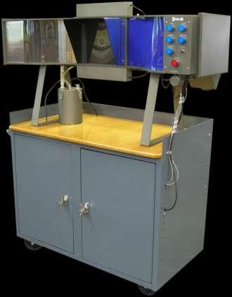
5 Tunnel Overview AEROLAB Flow Visualization Tunnel Honeycomb flow straightener Inlet Contraction Test Section Outlet Diffuser Main Control Panel Vapor Rake Airspeed Control Atomizer Reservoir Front View Auxiliary Blower Model Mount Spin Motor Outlet Aux. Blower Throttle Valve Back View


6 Main Control Panel AEROLAB Flow Visualization Tunnel Main Control Panel The POWER button is the main switch for the tunnel. Nothing can operate unless this switch is engaged. The air compressor (located inside the cabinet) will run for a short period of time when this button is activated. The compressor is audible. The FAN button activates the wind tunnel fan. The SMOKE button activates the atomizer


7 The SPIN CYLINDER button activates the cylinder electric motor. The VACUUM button activates the auxiliary blower. The blower provides pressurized air and/or vacuum to the vacuum/blowing models. The PURGE button provides a short blast of air to the vapor rake. This blast of air clears the rake of collected water droplets. The LIGHTS button activates the lights located above the below the test model. The AIR SPEED knob changes the airspeed through the wind tunnel. Turn the knob clockwise to slow the flow or counterclockwise to speed it up

 To fill the reservoir, lift the springloaded reservoir cap and slip in the supplied funnel.")
 Connect the FVT to power. 4) The main control panel (see page 6) is located on the front of the tunnel. Press the power button to enable the tunnel.")
 Press the SMOKE button. NOTE the atomizer reservoir will get HOT in approximately 15 minutes of continuous use.")

8 Basic Operation AEROLAB Flow Visualization Tunnel WARNING Never mix water and electricity. It can cause serious injury or death. Never connect or disconnect the FVT to power with wet hands or spilled water in the area. 1) With the FVT unplugged from power, check the reservoir water level. A sight glass is located on the side of the reservoir. If no water is needed, skip to step 3. 2) To fill the reservoir, lift the springloaded reservoir cap and slip in the supplied funnel. Add normal tap water while watching the sight glass. Marks on the sight glass indicate upper and lower water levels. Remove the funnel. 3) Connect the FVT to power. 4) The main control panel (see page 6) is located on the front of the tunnel. Press the power button to enable the tunnel. 5) Install / prepare the test model (see page 10) and close / latch the back access door. 6) Press the FAN button to start airflow. 7) Press the SMOKE button. NOTE the atomizer reservoir will get HOT in approximately 15 minutes of continuous use. As such, turn off the atomizer when it is not needed, for example, during a model change. If the reservoir gets hot to the touch, it must be allowed to cool down or damage to the atomizer could result. Water vapor streaklines will become visible in a few seconds. 8) Press the LIGHTS button to activate the lights. 9) The AIR SPEED knob can be adjusted as preferred. Turn the knob clockwise to slow down the airspeed or counterclockwise to speed up the airspeed
 From time to time, water droplets will collect in the vapor rake tubes. Momentarily, press the PURGE button to blow the droplets free of the vapor rake.")

. The blower is used for both vacuum and blowing. The conical fitting is a press-and-twist fit.")
9 Note The airspeed knob has an effect on water vapor density; at higher speeds the water vapor will be thinner than at slower speeds. 10) From time to time, water droplets will collect in the vapor rake tubes. Momentarily, press the PURGE button to blow the droplets free of the vapor rake. This purging may need to be done two or three times for best results. 11) The FVT can be completely turned off with the POWER button. However, it would be best to make certain the VACUUM and SPIN CYLINDER buttons are off before using the POWER button to avoid potential damage to the motor and auxiliary blower at restart. Auxiliary Blower and Throttle Valve Operation The auxiliary blower is located on the back side of the FVT. It is activated by means of the VACUUM button on the main control panel (see page 6). The blower is used for both vacuum and blowing. The conical fitting is a press-and-twist fit. set for vacuum set for blowing The throttle valve is located on the back frame member and is used to vary the vacuum and blowing intensity to the airfoil models. It can easily be adjusted from


 Identify the airfoil and wing model mount (shown to the left).")

10 the front of the FVT for precise settings. The valve is adjustable from fully-closed to fully-open in 90 of travel. Auxiliary Blower Throttle Valve Delta and Rectangular Wing Model Installation Note Although the AEROLAB Flow Visualization Tunnel is designed to give generations of service, care should be taken to avoid damage. Never force a model into the holder. If it does not go into position easily, investigate the situation before force is applied. 1) Identify the delta wing and flat plate model mounting post (shown to the left). 2) Identify the airfoil and wing model mount (shown to the left). Make certain it is installed in the back access door. To do so, press the narrow end of the model mount into the hole in the back access door. The mount has springloaded pins used to hold it in place. 3) Unlatch the back access door and slide the post through the model holder

 Adjust the pitch angle as desired.")
.")
 Note the brass tube and alignment pin located on the side of each model.")
11 4) While holding the post on the inside face of the back access door, install the locking nut to finger-tightness. 5) Slide the delta or rectangular wing model onto the mounting post. 6) Adjust the pitch angle as desired. 7) Turn the model mount in the back access door to align the model with the flow (the yaw angle). Airfoil and Venturi Model Installation 1) Unlatch and open the back access door. 2) Note the brass tube and alignment pin located on the side of each model. Note the two holes on the model holder. Slide the brass tube into the model holder and align the pin. Slide the model onto holder until the alignment pin engages with the pin hole

 Close and latch the back access door.")


12 3) For blowing / vacuum models, hold the model in one hand while pressing the auxiliary blower tube onto the brass model tube. Note The auxiliary blower tube should be pressed on only SLIGHTLY. Otherwise, removal will be difficult. 4) Close and latch the back access door. Spin Model Installation 1) Remove the airfoil and wing model mount. To do so, gently pull the mount back away from the tunnel while rocking side to side. 2) Install the spin model holder into the back access door as you would the airfoil and wing model mount. It, too, has spring-loaded pins used to hold it in place. 3) Slide the cylinder model onto the square motor shaft
, air is forced to move in only two dimensions (it cannot flow sideways to")

13 4) While holding the cylinder, thread the lock nut onto the motor shaft. This will prevent the cylinder from coming loose and scratching the tunnel window. 5) Close and latch the back access door. Model Operation and Experiment Suggestions Note - Because the airfoil models span the test area (they go from wall to wall), air is forced to move in only two dimensions (it cannot flow sideways to go around the ends of the models). This type of flow is termed two-dimensional. Airfoil w/ Blown Flap Airfoil w/ Vacuum Holes The Flap Model is intended to be used with and without blowing note the slot just in front of the flap hinge on the top of the airfoil. The flap can be adjusted down or up. The model demonstrates the Coanda Effect when used with blowing. The Coanda Effect is used to increase high angle-of-attack performance. The intensity of the blowing should be adjusted to the lowest possible setting to achieve the desired result. The Boeing C-17 Globemaster III employs blown flaps to increase performance. Vacuum applied to the top surface of a wing can increase high angle-of-attack performance. The Airfoil with Vacuum Holes serves to demonstrate this phenomenon. The intensity of the vacuum should be adjusted to the lowest possible setting to achieve the desired result. As an added experiment, use cellophane tape to partially or fully close holes and observe the result


 to increase performance. Visible on the top surface, there are two slots.")


14 Airfoil for Student Experimentation A large chamber has been cut into the top surface of the student experimentation airfoil. The chamber can be covered with tape or paper and holes or slots can be opened to experiment with the application of blowing or vacuum. Airfoil w/ Tangential Blowing Slots Venturi Similar to the Airfoil w/ Blown Flap, this model employs blowing (the Coanda Effect) to increase performance. Visible on the top surface, there are two slots. These slots have been designed such that the pressurized air is directed back and tangential (parallel) to the upper surface. Operate the model with and without blowing. Adjust the blowing intensity to the lowest possible setting to achieve the desired result. As an added experiment, use cellophane tape to partially or fully close slots and observe the result. The Venturi model serves to demonstrate the effect of a converging duct on moving air. Observe the streaklines as they pass through the model. Change the pitch angle of the model and observe the streaklines


15 Circular Cylinder (Spin Model) AEROLAB Flow Visualization Tunnel The Circular Cylinder serves to demonstrate the Magnus Effect. Operate the tunnel with and without the cylinder spinning. Note the direction of the spin and the effect on the streaklines. By observing the vapor lines, what is happening and why? Note The direction of rotation can be changed by switching the leads on the motor power supply located in the lower cabinet. Note - The delta and rectangular wing models allow air to flow around them just as it would on an actual aircraft. This is termed three-dimensional flow because the air is allowed to move in all three dimensions. Delta Wing The delta wing model serves to demonstrate the vortices generated by such a wing design. The wing s angle of attack can be adjusted by gently twisting the wing on the mounting post. Also, change the yaw, or side-slip, angle of the model by means of the model mount and observe the result. Discuss the advantages of a delta-wing aircraft. What is the benefit of the obvious vortices generated on the top of the wing? Rectangular Wing The rectangular wing model serves to demonstrate the vortices generated by such a wing design. The wing s angle of attack can be adjusted by gently twisting the wing on the mounting post. Discuss the vortices How do they affect the performance of the wing?
After installing the HEPA filters the discharge air should be monitored to ensure proper filtering efficiency. HEPA Filters
 D U S T C O N T A I N M E N T C A B I N E T S Technical Data General Description The Series 1532 inflow module comes in a variety of sizes and styles. Some of the included information will depend on the
Service Manual Air Tech Second Stage
 Service Manual Air Tech Second Stage Copyright 2002, Cressi-sub Revised 3/2002 2 Air Tech Second Stage Service Manual Contents BEFORE STARTING... 3 DISASSEMBLY... 3 PARTS CLEANING AND LUBRICATION... 9
Experiment (4): Flow measurement
: Flow measurement") Introduction: The flow measuring apparatus is used to familiarize the students with typical methods of flow measurement of an incompressible fluid and, at the same time demonstrate applications of the
Introduction: The flow measuring apparatus is used to familiarize the students with typical methods of flow measurement of an incompressible fluid and, at the same time demonstrate applications of the
ZTM AND ZTMB ZENNER TURBINE METERS INSTALLATION, MAINTENANCE AND SERVICING
 ZTM AND ZTMB ZENNER TURBINE METERS INSTALLATION, MAINTENANCE AND SERVICING INSTALLATION 1. The meter is intended for measuring potable, cold water in one direction. 2. The meter is to be installed in a
Centrifuge Operator / Service Manual
 3000 Centrifuge Centrifuge Operator / Service Manual cat.# 26230 & 26231 The Q-sep 3000 centrifuge complies with all requirements of UL standard 3101 20, Can/CSA C22.2 No. 1010.1, and Can/CSA C22.2 No.
READ AND SAVE THESE INSTRUCTIONS
 READ AND SAVE THESE INSTRUCTIONS Part #469003 Model Vektor -H Installation Operation and Maintenance Manual for Vektor-H Laboratory Exhaust System Receiving Greenheck model Vektor-H fans are thoroughly
Induction, Cooling, & Exhaust. Aviation Maintenance Technology 111 B B
 Induction, Cooling, & Exhaust Aviation Maintenance Technology 111 B - 112 B Unliscensed copyrighted material - W. North 1998 Unliscensed copyrighted material - W. North 1998 Induction = those locations
Z-Truck (Vertical Moving) Z-truck Flag. Y-Truck (Horizontal Moving) FIGURE 1: VIEW OF THE Z-TRUCK. Flexshaft Assembly
 Z-truck Flag. Y-Truck (Horizontal Moving) FIGURE 1: VIEW OF THE Z-TRUCK. Flexshaft Assembly") Checking and Replacing the AC Motor To remove and replace the AC Motor you will need the following tools: #2 Phillips screwdriver (magnetic tip preferred) Removing the AC Motor 1. Ready the machine by
Checking and Replacing the AC Motor To remove and replace the AC Motor you will need the following tools: #2 Phillips screwdriver (magnetic tip preferred) Removing the AC Motor 1. Ready the machine by
PHOENIX MINI-GUARDIAN
 PHOENIX MINI-GUARDIAN H. E. P. A. SYSTEM Therma-Stor Products A Division of DEC International Box 8050 Madison, WI 53708 Toll Free 1-800-533-7533 Local 1-608-222-5301 Table of Contents PHOENIX MINI-GUARDIAN
MODEL 905V OPERATING INSTRUCTIONS
 MODEL 905V OPERATING INSTRUCTIONS Quantek Instruments 183 Magill Drive Grafton, MA 01519 Tel: (508) 839-3940 Fax: (508) 819-3444 Email: sales@quantekinstruments.com GENERAL DESCRIPTION These instructions
READ AND FOLLOW ALL SAFETY INSTRUCTIONS SAVE THESE INSTRUCTIONS
 7.5 Swift Lock Ready Shape Tree (Patent Pending) Instructions IMPORTANT SAFETY INSTRUCTIONS When using electrical products, basic precautions should always be followed including the following: READ AND
5 Removal and replacement
 5 Removal and replacement This chapter describes the removal and replacement of field-replaceable units (FRUs) only. Removal and replacement strategy User-replaceable parts Covers Internal assemblies ENWW
DPL/DPL-AF SERIES PLENUM FANS OPERATION INSTRUCTIONS AND PARTS MANUAL MODELS: DPL/DPL-AF-12, 13, 15, 16, 18, 20, 22, 24, 27, 30, 33, 36 GENERAL SAFETY
 DPL/DPL-AF SERIES PLENUM FANS OPERATION INSTRUCTIONS AND PARTS MANUAL MODELS: DPL/DPL-AF-12, 13, 15, 16, 18, 20, 22, 24, 27, 30, 33, 36 GENERAL SAFETY Rotating parts on fans should not be exposed. Where
EXPERIMENTAL INVESTIGATION OF THE FLOWFIELD OF DUCT FLOW WITH AN INCLINED JET INJECTION DIFFERENCE BETWEEN FLOWFIELDS WITH AND WITHOUT A GUIDE VANE
 Proceedings of the 3rd ASME/JSME Joint Fluids Engineering Conference July 8-23, 999, San Francisco, California FEDSM99-694 EXPERIMENTAL INVESTIGATION OF THE FLOWFIELD OF DUCT FLOW WITH AN INCLINED JET
INSTALLATION INSTRUCTIONS
 INSTALLATION INSTRUCTIONS [1] Description: Tow Hitch Wire Harness Kit [2] Application: Nissan Rogue Note: Tow Harness application is limited to specific vehicle option packages that include tow harness
INSTRUCTIONS. US Patent Pending HVLP Turbine Guns
 INSTRUCTIONS 309317 INSTRUCTIONS This manual contains important warnings and information. READ AND KEEP FOR REFERENCE. Rev. A US Patent Pending HVLP Turbine Guns 10 psi (0.07 MPa,.7 bar) Maximum Inlet
How Do Helicopters Fly? An Introduction to Rotor Aeromechanics
 Audience: Grades 9-10 Module duration: 75 minutes How Do Helicopters Fly? An Introduction to Rotor Aeromechanics Instructor Guide Concepts: Airfoil lift, angle of attack, rotary wing aerodynamics, hover
DUST COLLECTOR (BOTTOM REMOVAL BAG & CAGE) INSTALLATION AND OPERATING INSTRUCTIONS
 INSTALLATION AND OPERATING INSTRUCTIONS") 4080 SE International Way. Suite B110, Milwaukie, OR 97222 (503) 654-0867 Fax: (503) 654-4671 email: ftech@filtertechnologyltd.com www.filtertechnologyltd.com DUST COLLECTOR (BOTTOM REMOVAL BAG & CAGE)
4080 SE International Way. Suite B110, Milwaukie, OR 97222 (503) 654-0867 Fax: (503) 654-4671 email: ftech@filtertechnologyltd.com www.filtertechnologyltd.com DUST COLLECTOR (BOTTOM REMOVAL BAG & CAGE)
HD 7700 Setup & Operator Manual
 HD 7700 Setup & Operator Manual Issue 1 December, 01 Performance Design Inc. The Heavy Duty Ultima (HD 7700) electric punch has been designed to punch most any job that may pass through your bindery or
Installation Instructions for the EVO3 Height-Adjustable Ultimate Short Shifter
 Installation Instructions for the EVO3 Height-Adjustable Ultimate Short Shifter for 1992-2005 325, 323, 318 and 1986-1994 525, 528, 535, 540 5-speed models only. (part number USSE3 and USSE5) Thank you
A practical investigation of the factors affecting lift produced by multi-rotor aircraft. Aaron Bonnell-Kangas
 A practical investigation of the factors affecting lift produced by multi-rotor aircraft Aaron Bonnell-Kangas Bonnell-Kangas i Table of Contents Introduction! 1 Research question! 1 Background! 1 Definitions!
CI 3000 Coil Inserter
 CI 3000 Coil Inserter Setup & Operator Manual Issue 1 April 02 Performance Design Inc. The CI 3000 plastic spiral inserter will bind books up to 1-1/8 (28.6mm) thick using coil diameters from 3/16 (5mm)
XS500 Load Bank. Read all instructions before using the load bank. Contents
 XS500 Load Bank Read all instructions before using the load bank Contents Contents... 2 1) Receiving... 4 a. Load Bank... 4 b. Manual... 4 2) Specifications... 5 a. Mechanical... 5 i. Lifting... 5 ii.
INDEX. Preflight Inspection Pages 2-4. Start Up.. Page 5. Take Off. Page 6. Approach to Landing. Pages 7-8. Emergency Procedures..
 INDEX Preflight Inspection Pages 2-4 Start Up.. Page 5 Take Off. Page 6 Approach to Landing. Pages 7-8 Emergency Procedures.. Page 9 Engine Failure Pages 10-13 Propeller Governor Failure Page 14 Fire.
CARENADO COPYRIGHTS. Normal & Emergency Checklist
 NORMAL PROCEDURES CHECKLIST PREFLIGHT CHECK Control wheel -- RELEASE BELTS Avionics -- OFF Master Switch -- ON Fuel quantity gauges -- CHECK Master switch -- OFF Ignition -- OFF Exterior -- CHECK FOR DAMAGE
OWNER S MANUAL REMOTE CONTROL, DUAL HEAD FOGGING SYSTEMS
 OWNER S MANUAL Sentinel II 5500 REMOTE CONTROL, DUAL HEAD FOGGING SYSTEMS Read all instructions carefully before starting the installation. Save this manual for future use. 2 OWNER S MANUAL SAFETY Always
Safety, Operation and Maintenance Instructions For Long & Short Nose Upholstery Air Stapler (NS10 & NS11)
") Safety, Operation and Maintenance Instructions For Long & Short Nose Upholstery Air Stapler (NS10 & NS11) Important: Drop 3 drops of oil into the stapler air inlet BEFORE first use. See page 2. Please
Safety, Operation and Maintenance Instructions For Long & Short Nose Upholstery Air Stapler (NS10 & NS11) Important: Drop 3 drops of oil into the stapler air inlet BEFORE first use. See page 2. Please
Pretest Module 21 Unit 4 Single-Phase Motors
 Pretest Module 21 Unit 4 Single-Phase Motors 1. What are the four main components of a single-phase motor? Rotor, stator, centrifugal switch, end bells and bearings 2. How is a rotating field created in
READ AND FOLLOW ALL SAFETY INSTRUCTIONS SAVE THESE INSTRUCTIONS
 5 Swift Lock Ready Shape Tree (Patent Pending) Instructions IMPORTANT SAFETY INSTRUCTIONS When using electrical products, basic precautions should always be followed including the following: READ AND FOLLOW
Requires Ductwork and Blower
 6' Protector XStream Laboratory Hood 9840600 is shown with SpillStopper Work Surface 9849800, Protector Acid Storage Cabinet 9901100 and Protector Standard Storage Cabinet 9900100. Requires Ductwork and
Reactor Startup Checklist
 Reactor Startup Checklist This checklist is for supplemental training of Graco distributors on Fusion and Reactor products. It is not a replacement for reading and understanding the manuals or other training
UV-AIRE AIR PURIFYING SYSTEM
 UV-AIRE AIR PURIFYING SYSTEM Model: UV-16/24 The UV-Aire unit is designed to emit powerful UVC Band light rays, which sterilize and reduce airborne microorganisms as they pass through a heating or air
YARWAY NARVIK MODEL 88 SPID SMALL PIPE INLINE DESUPERHEATER
 A wide range of desuperheaters, pneumatic actuators, strainers to satisfy all specifications of the power, pulp and paper industry and process gas applications FEATURES Fabricated construction Special
RediCoat by Nordson. Hopper and VBF Dolly Systems. Customer Product Manual Part A Issued 10/07
 RediCoat by Nordson Hopper and VBF Dolly Systems Customer Product Manual Part 1082648A Issued 10/07 This document is subject to change without notice. Nordson Corporation Amherst, Ohio USA 2 Table of Contents
PARTS TOOLS. Set Screw. Washer (2) Blue Bushing (2) Black Bushing (2) B&M Short Throw Shifter. Jam Nut Grease. Retaining Ring (2) Insert (2)
 Blue Bushing (2) Black Bushing (2) B&M Short Throw Shifter. Jam Nut Grease. Retaining Ring (2) Insert (2)") Installation Instructions SHORT THROW SHIFTER Fits: Porsche Boxter, Boxter S, 911, 996 Cayman & Cayman S models See Application Guide for specific year ranges and engine sizes Catalog # 45135 WORK SAFELY!
Installation Instructions SHORT THROW SHIFTER Fits: Porsche Boxter, Boxter S, 911, 996 Cayman & Cayman S models See Application Guide for specific year ranges and engine sizes Catalog # 45135 WORK SAFELY!
PHOENIX GUARDIAN H. E. P. A. SYSTEM
 PHOENIX GUARDIAN H. E. P. A. SYSTEM Therma-Stor Products Box 8050 Madison, WI 53708 Toll Free 1-800-533-7533 Local 1-608-222-5301 PHOENIX GUARDIAN Operation & Service Instructions Table of Contents 1.
NEC 2011 Code Changes
 NEC 2011 Code Changes Articles 280.21-300.50 CHANGES FROM 2008 TO 2011 CODE ARE IN RED Chapter 2 - Wiring and Protection ARTICLE 280 Surge Arresters, Over 1kV III. Connecting Surge Arresters 280.21 Connection
Complete HVAC Capability
 Air Handling Units Brochure 1110 January 2006 Complete HVAC Capability MEA Horizontal Draw-Thru to Size 65 Vertical Draw-Thru to Size 50 1000 to 60,000 CFM Forward Curved or Airfoil Wheels Inlet Vane Option
Firehawk Responder Second Stage Regulator
 Firehawk Responder Second Stage Regulator MAINTENANCE AND REPAIR MSA 511 (L) Rev. 4 MSA 2015 Prnt. Spec. 10000005389(I) Mat. 10096394 Doc. 10096394 Replacement Kits and Overhaul Kit P/N Description Firehawk
CHAPTER 21 ENVIRONMENT CONTROL. Section Title Page
 CHAPTER 21 ENVIRONMENT CONTROL Section Title Page 21-00 Description........................................ 21.1 21-10 Ventilation........................................ 21.3 21-11 Nose Vent................................
Hydro-wind Education Kit ASSEMBLY GUIDE
 Hydro-wind Education Kit ASSEMBLY GUIDE Model No.: FCJJ-26 Warning To avoid the risk of property damage, serious injury or death: This kit should only be used by persons 12 years old and up, and only under
Breezair TBA 550 Installation Manual
 Breezair TBA 550 Installation Manual Table of Contents ITEM Safety Instructions Specifications Exploded View of the Air Cooler Components of the Air Cooler Dismantling the Air Cooler Installing the Transition
VANEAXIAL & TUBEAXIAL FANS
 BULLETIN 482 July 2008 VANEAXIAL & TUBEAXIAL FANS Type "S" Belt Driven Featuring Welded Steel Propellers Models VSBD & TSBD Model TSBD Belt Driven Tubeaxial Type "S" Vaneaxial & Tubeaxial Fans For applications
Part # Regulator Rebuild Kit for SuperFlow and SuperFlow 350 Regulators
 Part #525-309 Regulator Rebuild Kit for SuperFlow and SuperFlow 350 Regulators Tools Required Part Number Description Qty 510-011 O-ring 1 510-014 O-ring 1 510-552 Exhaust Valve 1 510-553 Diaphragm 1 520-032
Series Roll Seal
 INSTALLATION / OPERATION / MAINTENANCE SERIES 00-4 700 Series Roll Seal DESCRIPTION The Cla-Val Model 00-4 Roll Seal valve is a hydraulically operated valve used to control liquid flow by means of a flexible
KEEP FOR FUTURE REFERENCE DC VACUUM BACK-UP SYSTEM READ ALL INSTRUCTIONS AND WARNINGS BEFORE USING THIS PRODUCT
 KEEP FOR FUTURE REFERENCE P.O. Box 368 908 West Main Laurel, MT USA 59044 phone 800-548-7341 phone 406-628-8231 fax 406-628-8354 INSTRUCTIONS International Version STOCK NUMBERS: SEE SPECIFICATIONS DC
Motor/Drive Housing and Motor Fan Replacement Kits
 Instructions Motor/Drive Housing and Motor Fan Replacement Kits 311301C Use with MAGNUM XR, SR7, ProX and ProLTS Model Sprayers XR Motor/Drive Housing Replacement Kit: 287773 SR7 Motor/Drive Housing Replacement
Chapter 11: Flow over bodies. Lift and drag
 Chapter 11: Flow over bodies. Lift and drag Objectives Have an intuitive understanding of the various physical phenomena such as drag, friction and pressure drag, drag reduction, and lift. Calculate the
1. CONDITIONS FOR USE 2. SAFETY
 1. CONDITIONS FOR USE This micro abrasive blaster may only be operated: Indoors; Below 6500 ft above sea level altitude; Ambient air temperature between 40-105 F (5-40 C); Maximum relative humidity of
Model: UV-16R/24 READ THESE INSTRUCTIONS CAREFULLY AND COMPLETELY BEFORE PROCEEDING WITH THE INSTALLATION.
 U V - AIRE AIR PURIFYING S YSTEM Model: UV-16R/24 ITEMS INCLUDED IN KIT: 1-24Volt UV-Aire Ballast Assembly 1-Mounting Base 1-Ultraviolet Lamp 6-Sheet Metal Mounting Screws 1-Instruction Sheet 1-Fiberglass
WHIRLWIND. Owner s Manual 375RV Series (Rev ) Model: 375RV Serial Number: 375RV- Manufacture Date: A V I A T I O N WHIRL WIND AVIATION
 Model: 375RV Serial Number: 375RV- Manufacture Date: A V I A T I O N WHIRL WIND AVIATION") WHIRLWIND A V I A T I O N M a nufacturer of Composite Constant Speed P r o pellers Model: 375RV Serial Number: 375RV- Manufacture Date: Owner s Manual 375RV Series (Rev 2014-3) WHIRL WIND AVIATION 1419
WHIRLWIND A V I A T I O N M a nufacturer of Composite Constant Speed P r o pellers Model: 375RV Serial Number: 375RV- Manufacture Date: Owner s Manual 375RV Series (Rev 2014-3) WHIRL WIND AVIATION 1419
Maintenance Information
 16572679 Edition 2 May 2014 Air Drill QP Series Maintenance Information Save These Instructions Product Safety Information WARNING Failure to observe the following warnings, and to avoid these potentially
Owners Manual. Table of Contents 4.1. INTRODUCTION SPEEDS FOR NORMAL OPERATION CHECKLIST & PROCEDURES 4
 NORMAL OPERATIONS Table of Contents 4.1. INTRODUCTION 2 4.2. SPEEDS FOR NORMAL OPERATION 2 4.3. CHECKLIST & PROCEDURES 4 4.3.1. PREFLIGHT INSPECTION 4 4.3.2. BEFORE STARTING ENGINE 8 4.3.3. STARTING ENGINE
.3 Section Vibration Isolation and Seismic Control..2 ANSI/AMCA 210/ASHRAE 51 Laboratory Methods of Testing Fans for Rating.
 Issued 2005/06/01 Section 15831 Commercial Fans Page 1 of 6 PART 1 GENERAL 1.1 RELATED SECTIONS.1 Section 01355 Waste Management and Disposal..2 Section 15053 Motors, Drives and Guards..3 Section 15072
Tube Topics. (a) (b) (c) Figure 1. The interior of a tetrode: (a) mesh filament, (b) control grid (c) screen grid
 (b) (c) Figure 1. The interior of a tetrode: (a) mesh filament, (b) control grid (c) screen grid") 1 Tube Topics Section 1: Basic Tube Design A vacuum tube consists of a vacuum envelope containing various electronic elements used to emit, control, and collect a flow of electrons. A filament or cathode
1 Tube Topics Section 1: Basic Tube Design A vacuum tube consists of a vacuum envelope containing various electronic elements used to emit, control, and collect a flow of electrons. A filament or cathode
I n s t r u c t i o n M a n u a l. Instruction Manual SPECIFICATION
 I n s t r u c t i o n M a n u a l Instruction Manual SPECIFICATION - Wingspan: 3200mm (125,9 in) - Length: 1650mm (64,9 in) - Flying weight: 3000gr 3200gr - Wing area: 64.5 dm2 - Wing loading: 46g/dm2
Introduction to Johnson Controls Dampers
 Damper and Actuator Product Guide 268.1 Damper Engineering Section Product Bulletin Issue Date 1297 Introduction to Johnson Controls Dampers For over 100 years, Johnson Controls has been the industry leader
Typical Fuel Systems - An Overview
 Typical Fuel Systems - An Overview Richard Skiba Skiba, R. (1999). Typical Fuel Systems An Overview, Pacific Flyer, March. Skiba, R. (2001). 'Typical Fuel Systems - An Overview'. Air Sport: The Home of
Service Manual Air Plus Second Stage
 Service Manual Air Plus Second Stage Includes XS Series Second Stage Copyright 2002, Cressi-sub Revised 3/2002 2 Air Plus Second Stage Service Manual Contents BEFORE STARTING... 3 DISASSEMBLY... 3 PARTS
Flow Behavior and Friction Factor. in Internally Grooved Pipe Wall
 Adv. Studies Theor. Phys., Vol. 8, 2014, no. 14, 643-647 HIKARI Ltd, www.m-hikari.com http://dx.doi.org/10.12988/astp.2014.4573 Flow Behavior and Friction Factor in Internally Grooved Pipe Wall Putu Wijaya
READ AND SAVE THESE INSTRUCTIONS. Air Boss MP600M Vertical Air Flow Mist Precipitator Industrial Applications. TRION
 READ AND SAVE THESE INSTRUCTIONS Vertical Air Flow Mist Precipitator Industrial Applications TRION Vertical Air Flow Mist Precipitator for Industrial Applications Table of Contents Design...2 Installation...2
Protector XStream Laboratory Hood is shown with SpillStopper Work Surface , Protector Acid Storage Cabinet and Protector
 Protector XStream Laboratory Hood 9840600 is shown with SpillStopper Work Surface 9849800, Protector Acid Storage Cabinet 9901100 and Protector Standard Storage Cabinet 9900100. Protector XStream Laboratory
NSGV PT-1000 PORTABLE WELDING STATION I, O & M MANUAL
 APPLICATION OF DUST CONTROL EQUIPMENT: CAUTION - Warning Improper operation of dust control system may contribute to conditions in the work area or facility that could result in severe personal injury
Cylinder head/gasket, replacing
 1(16) Cylinder head/gasket, replacing Special tools: 951 2666, 951 2767, 999 5450, 999 5452, 999 5454, 999 5670, 999 5718, 999 5719, 999 5750, 999 5972 Removing the cylinder head gasket Note! As the illustrations
GRAVITY FEED SPRAY GUN & CUP SPECIFICATIONS. Operating Instructions Warning Information Parts Breakdown. Fluid Orifice mm. Air Inlet:...
 Operating Instructions Warning Information Parts Breakdown SPECIFICATIONS Fluid Orifice... 1.4mm Air Inlet:...1/4 NPT Rec. Max. Inlet Pressure:...50 PSI CFM:... 3.1 at 50 PSI Nozzle Pressure... 10 PSI
MODEL ELC-12/40-CVM-D BATTERY CHARGER
 NATIONAL RAILWAY SUPPLY MODEL ELC-12/40-CVM-D BATTERY CHARGER Installing, Operating and Service Instructions for the ELC-12/40-CVM-D Solid State Charger PLEASE SAVE THESE IMPORTANT SAFETY AND OPERATING
ATD-6810 SPRAY GUN W/CUP INSTRUCTION MANUAL
 ATD-6810 SPRAY GUN W/CUP INSTRUCTION MANUAL Read this Instruction Manual carefully and understand it completely, basic precaution should be strictly followed to prevent the damage to the tool and injury
Keeping You Cool Under Pressure
 Installation Instruction for 92-93 GM 6.5L Turbo Diesel Series 3500-4 Wheel Drive Pickup and Series 1500, 2500, 3500 4 Wheel Drive Suburban Intercooler System (Part No. 2-436) TOOLS REQUIRED: 1.) Normal
GENERAL AND PLANNING INFORMATION
 SOLAR CAR NO SOLDER CONTENTS: Section 1: General and Planning Information Section 2: Components and Material Required Section 3: Construction Section 4: Wiring Section 5: Testing Section 6: Theory DESCRIPTION
Bench Top Tube Bender
 Bench Top Tube er User s Manual Electric and manual units s fractional and metric tubing CE compliant 2 Bench Top er User s Manual Contents Safety Instructions... 2 Technical Data... 2 Tubing Data... 3
Foss Electric Milko-Scope II Meter Manual
 Foss Electric Milko-Scope II Meter Manual General Description Adapted from the Technical Bulletin 16800-6GB November 1980 1. Measuring Principle The Milko-Scope meter collects a certain part of the total
AMD-33. Air Measuring Station with VCD-33 Control Damper. Application and Design. Features & Control Options
 Application and Design The combines the functionality of an accurate airflow measuring station and a low leakage control damper into one compact assembly that both measures and regulates airflow volumes
Pretium Wall-Mountable Housing (PWH-02P/-04P/- 06P/-12P and FZB-02P-JB)
") 1. Precautions 2. Carton Contents Pretium Wall-Mountable Housing OR Fiber Zone Box (FZB-02P-JB) PWH-02P and FZB-02B-JP have: (15 inches) edge grommet (1) Laser warning label (2) Fiber identification labels
1. Precautions 2. Carton Contents Pretium Wall-Mountable Housing OR Fiber Zone Box (FZB-02P-JB) PWH-02P and FZB-02B-JP have: (15 inches) edge grommet (1) Laser warning label (2) Fiber identification labels
TWO-STAGE HYDRAULIC PUMP. RWP55-IBT-Air
 ORIGINAL INSTRUCTIONS Form No.1000458 5 SPX Corporation 5885 11th Street Rockford, IL 61109-3699 USA Tech. Services: (800) 477-8326 Fax: (800) 765-8326 Order Entry: (800) 541-1418 Fax: (800) 288-7031 Internet
MODEL 6010A 6 12 VOLT BATTERY CHARGER ASSOCIATE
 MODEL 600A 6 VOLT BATTERY CHARGER ASSOCIATE IMPORTANT SAFETY INSTRUCTIONS. SAVE THESE INSTRUCTIONS. This manual contains important safety and operating instructions for the battery charger you have purchased.
INSTALLATION INSTRUCTIONS EUROLINE/EUROLINE PRO WALL MOUNT HOOD
 Read and Save These Instructions All Hoods Must Be Installed By A Qualified Installer INSTALLATION INSTRUCTIONS EUROLINE/EUROLINE PRO WALL MOUNT HOOD Read All Instructions Thoroughly Before Beginning Installation
Installation Vertical Pump: Installation 'CM' and 'CDM' Style: Operation:
 Installation Vertical Pump: Gusher vertical end suction pumps with integral shaft is easily installed and put into service. With the one piece shaft design there is no couplings to align, no shims or no
 www.odometergears.com Mercedes-Benz Mechanical Odometer Repair This how to can be used for all mechanical repairs as the only difference will be the removal of the instrument cluster. http://www.dieselgiant.com/repairyourodometer.htm
BASIC CONNECTION PRINCIPLE
 READ & SAVE ASSEMBLY & OPERATION INSTRUCTIONS There are four basic individual units in this unit, AMAZING AIM N SHOOT, AMAZING ROBOTIC DUCK, AMAZING TURBOAIR and AMAZING MAZE CHALLENGE. By changing different
SAFARI Helicopter Flight Control Rigging Manual Revision 9 4/3/2010 CHR International Inc.
 SAFARI Helicopter Flight Control Rigging Manual Revision 9 4/3/2010 CHR International Inc. The following procedures are meant as a guide to assist you in the safe configuration of your helicopter s Flight
Oreck Magnesium Series Service Manual. The Oreck Manufacturing Company
 Oreck Magnesium Series Service Manual The Oreck Manufacturing Company 08/2012 10/2011 The Oreck Manufacturing Company Contents Covering all Magnesium Upright Models Including: LW100, LW125, LW1000, AND
AMD-33 Air Measuring Station with VCD-33 Control Damper
 Application and Design Construction Standard Optional Frame Material Galvanized Steel - Frame Material Thickness 16 ga. (1.5mm) 12 ga. (2.7mm) Frame Type 5 in. x 1 in. hat channel - Blade Material Galvanized
NSGV EVE-ER I, O, & M MANUAL
 TABLE OF CONTENTS Rail Layout.. Page 1 Support Placement...Page 1 Rail Assembly.Page 1 Rail Duct Connections.. Page 2 Rubber Lip Installation.. Page 3 Pneumatic End Stop. Page 4 End Stop. Page 4 End Cap..
RECOMMENDED MOTOR AND BATTERY SET UP
 SPECIFICATION - Wingspan: 6000mm (236.2 in) - Length: 2873mm (113.1 in) - Flying weight: 14-18 kg - Wing area: 219.4 dm2 - Wing loading: 64g/dm2 - Wing type: HQ airfoils - Covering type: Genuine ORACOVER
INSTALLATION INSTRUCTIONS WALL MOUNT HOOD
 Read and Save These Instructions All Hoods Must Be Installed By A Qualified Installer INSTALLATION INSTRUCTIONS WALL MOUNT HOOD Read All Instructions Thoroughly Before Beginning Installation WARNING -
ENGINE STARTING PERFORMANCE EVALUATION AT STATIC STATE CONDITIONS USING SUPERSONIC AIR INTAKE
 24 TH INTERNATIONAL CONGRESS OF THE AERONAUTICAL SCIENCES STARTING PERFORMANCE EVALUATION AT STATIC STATE CONDITIONS USING SUPERSONIC AIR INTAKE Author1* Takashi Nishikido Author2* Iwao Murata Author3**
SECTION AXIAL HVAC FANS
 SECTION 233413 - AXIAL HVAC FANS 1. PART 1 GENERAL 1.1. RELATED DOCUMENTS A. Drawings and general provisions of the Contract, including General and Supplementary Conditions and Division 01 Specification
WEBER CARBURETOR TROUBLESHOOTING GUIDE
 This guide is to help pinpoint problems by diagnosing engine symptoms associated with specific vehicle operating conditions. The chart will guide you step by step to help correct these problems. For successful
Baked Enamel, Epoxy, Hi Pro Polyester, Industrial Epoxy, Kynar/Hylar (70%) Permatector. Single or Reverse Flange 8 x 6 (203 x 178)
 Permatector. Single or Reverse Flange 8 x 6 (203 x 178)") Application and Design The is an extremely low leakage damper designed to meet the highest standards established for commercial control dampers. The is intended for application in medium to high pressure
Application and Design The is an extremely low leakage damper designed to meet the highest standards established for commercial control dampers. The is intended for application in medium to high pressure
A. Each cabinet must be constructed and installed in accordance with EN12469:2000.
 BIOLOGICAL SAFETY CABINETS Class II, Biological Safety Cabinet PART 1 GENERAL 1.1 REFERENCES The publications listed below form a part of this section to the extent referenced. The publications are referred
Norfolk & Western Y6b Mallet
 2002 Kohs & Company, Inc - Clarkston, Michigan 48348 Norfolk & Western Y6b Mallet OPERATION AND MAINTENANCE INSTRUCTIONS The Kohs & Company Norfolk & Western Y6b locomotive is an exact scale replica of
Norfolk & Western Y6a Mallet
 2003 Kohs & Company, Inc - Clarkston, Michigan 48348 Norfolk & Western Y6a Mallet OPERATION AND MAINTENANCE INSTRUCTIONS The Kohs & Company Norfolk & Western Y6a locomotive is an exact scale replica of
Honda CRV Oil Change
 1995-2001 Honda CRV Oil Change Change the oil in your '95-'01 Honda CRV to improve engine performance and longevity. Written By: Phillip Takahashi ifixit CC BY-NC-SA www.ifixit.com Page 1 of 16 INTRODUCTION
KHR Series Regulators
 KHR Series Regulators Maintenance Instructions Kit Contents retainer Poppet Poppet spring Poppet damper Outer body seal Inner body seal Upper piston seal seal backup ring Main piston seal vent seal Self-vent
PRODUCT OPERATING MANUAL
 PRODUCT OPERATING MANUAL PANBLAST TM CS37 SUCTION BLAST CABINET Manual Number: ZVP PC 0069 00 SECTION 1. GENERAL INFORMATION 2. ASSEMBLY & INSTALLATION INSTRUCTIONS 3. OPERATING INSTRUCTIONS 4. MAINTENANCE
MANUAL INSTALLATION. Active Chilled Beam Linear. ACBL Series. v101 Issue Date: 04/10/ Price Industries Limited. All rights reserved.
 MANUAL INSTALLATION Active Chilled Beam Linear ACBL Series v11 Issue Date: 4/1/18 218 Price Industries Limited. All rights reserved. TABLE OF CONTENTS Product Overview Before You Start...1 Maintenance...1
Safety Instructions, Installation & Operator s Manual For
 Safety Instructions, Installation & Operator s Manual For #6-3173 TWIN BAG GRASS CATCHER KIT FOR 38 YARD CRUISERS SERIES 2 MODEL YZ145382BVE IMPORTANT! THIS KIT NOT INTENDED FOR USE ON ANY SERIES OF HZ/HZS
Applied Fluid Mechanics
 Applied Fluid Mechanics 1. The Nature of Fluid and the Study of Fluid Mechanics 2. Viscosity of Fluid 3. Pressure Measurement 4. Forces Due to Static Fluid 5. Buoyancy and Stability 6. Flow of Fluid and
WHIRLWIND. Owner s Manual Series (Rev ) Serial Number: Manufacture Date: A V I A T I O N Model: WHIRL WIND AVIATION
 Serial Number: Manufacture Date: A V I A T I O N Model: WHIRL WIND AVIATION") WHIRLWIND A V I A T I O N Model: 100-4 Serial Number: 100-4- Manufacture Date: M a nufacturer of Composite Constant Speed P r o pellers Owner s Manual 100-4 Series (Rev 2014-2) WHIRL WIND AVIATION 1419
WHIRLWIND A V I A T I O N Model: 100-4 Serial Number: 100-4- Manufacture Date: M a nufacturer of Composite Constant Speed P r o pellers Owner s Manual 100-4 Series (Rev 2014-2) WHIRL WIND AVIATION 1419
AMD-42V Air Measuring Station with VCD-42V Control Damper
 Application and Design Construction Standard Optional Frame Material Galvanized Steel - Frame Material Thickness 16 ga. (1.5mm) 12 ga. (2.7mm) 14 ga. (2mm) Frame Type 5 in. x 1 in. hat channel - Blade