Pneumatic Rotary Actuators. PRO-PRN Series PRO-PRN. PDE2613TCUK Pneumatic Rotary Actuators & Airmotors
|
|
|
- Dulcie Murphy
- 5 years ago
- Views:
Transcription


1 Pneumatic Rotary Actuators Series 173

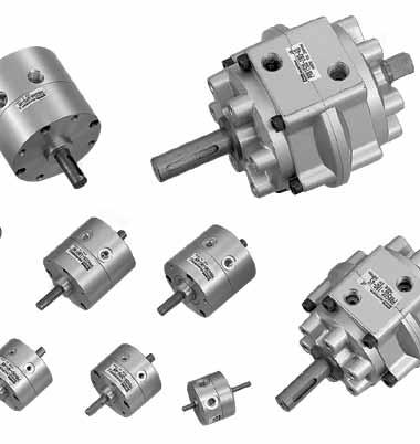
2 Rotary actuators are an efficient and easy way to generate torque from compressed air, in a very compact size. They are ideal for the compact applications in a wide range of industries such as, packaging, process, electronics etc. Wide range A full range of 9 sizes is available, the 8 largest sizes are single or double vane type (with double effective torque). or the PRN High Torque, a series of customized cushion units (CRN) are available for high energy applications. Easy-to-use oscillating angles Two oscillation reference points of 45 and 90 and three oscillating angles of and 270 are featured on the PRN ranges to match the most frequently uses. On the PRO range, the oscillation angle can be adjusted to the exact requirement. Stable operation The unique sealing design minimises leakages. It assures low speed oscillation and stable, smooth operation even at low operating pressures and speeds. Durability to high operating temperatures Dry dehumidified air may supply the rotary actuators within operating temperature range of -5 C to 80 C (PRN range -5 C to +60 C). Outstanding durability A solid vane shaft and built-in damper are combined with a unique sealing design to ensure outstanding durability. PRN50 and higher models are able to operate much greater loads with the incorporation of a Hydro-cushion. 174
 PROA3S 38 Single PROA10S 120 vane PROA20S 210 PRO30SE 410 oot plate PROA3D 86 Double PROA10D 254 Vane PROA20D 470 PRO30DE 950 PRN Miniature Rotary Actuators (fixed oscillating angle)")
3 PRO Miniature Rotary Actuators (adjustable oscillating angle) lange plate Switch unit Vane Model Effective torque (N.cm at 6 bar) PROA3S 38 Single PROA10S 120 vane PROA20S 210 PRO30SE 410 oot plate PROA3D 86 Double PROA10D 254 Vane PROA20D 470 PRO30DE 950 PRN Miniature Rotary Actuators (fixed oscillating angle) lange plate Switch unit Vane Model Effective torque (N.cm at 6 bar) PRNA1S 15,6 PRNA3S 38 Single PRNA10S 120 vane PRNA20S 210 PRN30SE 410 oot plate PRNA1D 34,7 PRNA3D 86 Double PRNA10D 254 Vane PRNA20D 470 PRN30DE 950 PRN High Torque (fixed oscillating angle) Hydro-cushioning Standard sensing Vane Model Effective torque (N.cm at 6 bar) PRN50SE 590 Single PRN150SE 1800 vane PRN300SE 3450 PRN800SE Sensing and&j hydro-cushioning PRN50DE 1280 Double PRN150DE 4150 Vane PRN300DE 8300 PRN800DE lange plate oot plate 175
 angle Single vane PROA3S-0-90 38 30 to 180 PROA10S-0-90 120 30 to 180 PROA20S-0-90 210 30 to 180")


4 PRO Miniature series - Adjustable oscillating angle - Order Codes Standard models Order code Torque at 6 bar (N.cm) angle Single vane PROA3S to 180 PROA10S to 180 PROA20S to 180 PRO30SE to 270 Oscillation starting point and oscillation angle Double vane PROA3D to 90 PROA10D to 90 PROA20D to 90 PRO30DE to 90 Note : Rotary actuators with variable oscillating angle are shipped with fixed reference point stopper. The angle setting stopper is attached but not fixed. This must be fixed securely before use. Rotary Actuator mountings PROA3S, PROA10S, PROA20S reference point at 90 or Rotary Actuator lange mounting oot mounting Port position angle angle reference point PROA3S/D PRN3-P PRN3-L PROA10S/D PRN10-P PRN10-L PROA20S/D PRN20-P PRN20-L PRO30SE/DE PRN30-P PRN30-L The mountings are provided with set screws Switch units Variable switch position, solid state NPN or PNP. PRO30SE reference point at 45 Port position 45 reference point 30 or Rotary Actuator NPN PNP PROA3S/D R-3PRO P-3PRO PROA10S/D R-10PRO P-10PRO PROA20S/D R-20PRO P-20PRO PRO30SE/DE R-30PRO P-30PRO Protective cover and stopper unit angle angle PROA3D, PROA10D, PROA20D, PRO30DE &J reference point at 45 Port position 45 angle reference point 30 angle or Rotary Actuator Protective cover Stopper unit PROA3S/D PRO3-K RO3-U PROA10S/D PRO10-K RO10-U PROA20S/D PRO20-K RO20-U PRO30SE/DE PRO30-K RO30-U Maintenance kits The maintenance kit consists in the vane shaft, shoe seal and shaft O'rings or Rotary Actuator Single vane Double vane PROA3S PRNA3S-PS PROA3D PRNA3D-PS PROA10S PRNA10S-PS PROA10D PRNA10D-PS PROA20S PRNA20S-PS PROA20D PRNA20D-PS PRO30SE PRN30S-PS PRO30DE PRN30D-PS 176
5 PRO Miniature series - Adjustable oscillating angle - Technical data Technical specification PRO Rotary Actuators Unit PROA3S PROA10S PROA20S PRO30SE Vane Single vane Air condition iltered (5µ) lubricated or non-lubricated angle 30 to to to to 270 reference point Port size M5 M5 M5 G1/8 Minimum operating pressure bar 1,0 1,0 0,8 1,0 Operating pressure bar 2 to 7 2 to 7 2 to 10 2 to 10 Operating temperature C -5 to 80-5 to 80-5 to 80-5 to 60 Maximum operating frequency cycles/mn 150 (at 180 ) 150 (at 180 ) 120 (at 180 ) 90 (at 270 ) Internal volume cm Allowable radial load N Allowable thrust load N Allowable energy mj Weight kg 0,085 0,170 0,280 0,510 PRO Rotary Actuators Unit PROA3D PROA10D PROA20D PRO30DE Vane Double vane Air condition iltered (5µ) lubricated or non-lubricated angle 30 to to to to 90 reference point Port size M5 M5 M5 G1/8 Minimum operating pressure bar 0,7 0,7 0,6 0,8 Operating pressure bar 2 to 7 2 to 7 2 to 10 2 to 10 Operating temperature C -5 to 80-5 to 80-5 to 80-5 to 60 Maximum operating frequency cycles/mn 240 (at 90 ) 240 (at 90 ) 180 (at 90 ) 180 (at 90 ) Internal volume cm 3 2,8 8, Allowable radial load N Allowable thrust load N Allowable energy mj Weight kg 0,087 0,180 0,290 0,530 Notes : The allowable energy differs from that of PRN series. Maximum operating frequency is given at 5 bar operating pressure (unloaded). Make sure to use the PRO rotary actuators within the allowable energy. Check if the required energy is lower than the allowable energy. If not, use end stoppers directly on the load. The PRO with keyways are provided with keys. Materials specification PRO PROA3, PROA10, PROA20 PRO30 Body Aluminium alloy Aluminium alloy Solid vane shaft Steel + resin + Hydr. Nitrile Steel + resin + Nitrile Shoe Resin Resin Shoe seal Hydrogenated Nitrile Nitrile O-ring Hydrogenated Nitrile Nitrile Screws, claw, stoppers, locknut Steel Steel Effective torque (N.cm) Operating pressure (bar) Model n Single vane PROA3S PROA10S PROA20S PRO30SE Switch units specification Switch unit type R- P- Application Relay, PLC, IC circuit Output method NPN PNP Mounting Switch position adjustable Operating voltage DC5~30V DC10~30V Operating current 5 to 200mA 5 to 200mA Indicating lamp Lights up at ON Consumption 20mA at 24V 14mA at 24V 10mA at 12V 7mA at 12V 4mA at 5V Max.leakage current 10 µa Internal voltage drop 1,5 V Average operating time 1 ms Shock resistance 490m/s 2 Operating temperature 5 to 60 C Protection IP67 Lead wire 1 m, 3 core, oil resistant Response range 23 ±7 Hysteresis Approx. 2 Double vane PROA3D PROA10D PROA20D PRO30DE Type R- P- Type 177
6 PRO Miniature series - Adjustable oscillating angle - Technical data (cont) time range Note : The PRO rotary actuators must be operated within the range of the charts shown; otherwise, they exhibit a stick-slip motion. time (s) time (s) angle ( ) angle ( ) time (s) time (s) angle ( ) angle ( ) Setting the oscillation angle The rotary actuators are delivered with the reference point stopper fixed and the angle setting stopper non fixed. The angle setting stopper has to be set in position according to the angle required, it can be attached at intervals of 15. ine adjust screw Reference point stopper Minimum angle setting Angle setting stopper Stopper mounting pitch angle setting and external stopper specifications angle Model n PROA3S PROA10S PROA20S PRO30SE PROA3D PROA10D PROA20D PRO30DE Oscillation angle setting range 30 to to to to to to to to 90 reference point Minimum angle setting Maximum angle setting Pitch for angle setting ine adjustment range Angle -9 to +6-9 to +6-9 to +6-9 to +6-9 to +6-9 to +6-9 to +6-9 to +6 ref point ±3 ±3 ±3 ±3-1 to +3 ±3 ±3 ±3 At max angle setting -9 to +6-9 to +6-9 to +6-9 to +3-9 to +1-9 to +3-9 to +3-9 to
7 PRO Miniature series - Adjustable oscillating angle Setting the oscillation angle (cont.) When the angle setting equals the stopper mounting pitch (15 ) 1. Place the stopper into the tapped hole corresponding to the & intended angle and fix it. When mounting the stopper, use the angle setting marks provided every 30, near the tapped hole. When the angle setting lies between two 15 stops 1. When the required angle lies between two 15 stops, fix the stopper into the tapped holes as shown in the diagram herebelow. Angle setting mark When the required angle is located in the 6 side (from the reference point), insert the stopper making contact with the set screw on this side. When the required angle is located in the 9 portion, insert the stopper making contact with the set screw on the other side (from the reference point). 2. Then, rotate the fine adjust screws on the reference point stopper and the angle setting stopper until the correct angle is obtained. After completing the angle setting, the locknut must be tightened. 2. Then, rotate the fine adjust screw fitted to the stopper to obtain the required angle. After completing the angle setting, the locknut must be tightened. Claw ine adjust screw Reference set screw Mounting pitch Required angle Locknut Adjust with the fine adjust screw Switch mounting orientation The 2 types of switches (-3L and -3R) included in the switch unit have to be oriented in accordance to the table and diagrams herebelow : angle Orientation of switches 30 to 186 A 187 to 270 B Orientation A Max. sensivity position Port position Min. angle setting 24 Orientation B Port position Max. sensivity position Max. sensivity position Max. sensivity position Setting the switch position Mount the switch unit on the body using the set of screws. or clamping torque, refer to the table below Model Clamping torque (N.cm) PROA3S/D 6 to 10 PROA10S/D 10 to 20 PROA20S/D and PRO30SE/DE 20 to 30 Composition of switch unit Point of highest sensitivity Switch case set screw Magnet Switch adjust screws Plate clamp screw Angle marking Switch case Magnet holder set screw Magnet holder PRO body Adjusting the switch Loosen the switch adjust screws, make the point, at which the highest sensitivity is obtained, match with the angle marking equivalent to the actuator setting, and retighten the switch adjust screws torque of 40 to 50 N.cm. Since the angle markings are provided just for reference, make a final adjustment by checking if the LED is on. Replacing the switch To remove the switch, remove the switch adjust screws and plate clamp screw. To mount a switch, reverse the procedure for removal. Adjust the switch position after completion of mounting. 179
8 PRO Miniature series - Adjustable oscillating angle - Dimensions (mm) PROA3S Port 2 x M5 reference point Reference point stopper Claw Angle setting stopper 3 x M3 depth 6 angle 30 to 180 Minimum angle setting 30 Maximum angle setting 180 Stopper mounting pitch 15 PROA3D reference point Port 2 x M5 Reference point stopper Minimum angle setting 30 Stopper mounting pitch 15 Claw Maximum angle setting 90 3 x M3 depth 6 angle 30 to 90 Angle setting stopper With protection cover With foot plate mounting With flange plate mounting Note : A foot plate can be fitted turned by steps of 60 from the original position Note : A flange plate can be fitted turned by steps of 120 from the original position With switch unit (variable switch position) R switch unit U switch unit Note : or switch unit-mounting hardware combinations, refer to the required dimensions in each fig. 180
9 PRO Miniature series - Adjustable oscillating angle - Dimensions (mm) PROA10S 3 x M3 depth 6 Port 2 x M5 Reference point stopper Claw Angle setting stopper PROA10D reference point angle 30 to 180 reference point angle 30 to 90 Port 2 x M5 Reference point stopper Minimum angle setting 30 Stopper mounting pitch 15 Stopper mounting pitch 15 Claw 3 x M3 depth 6 Maximum angle setting 90 Angle setting stopper With protection cover With foot plate mounting With flange plate mounting Note : A foot plate can be fitted turned by steps of 60 from the original position With switch unit (variable switch position) Note : A flange plate can be fitted turned by steps of 120 from the original position R switch unit U switch unit Note : or switch unit-mounting hardware combinations, refer to the required dimensions in each fig. 181
10 PRO Miniature series - Adjustable oscillating angle - Dimensions (mm) PROA20S Keyway Width x depth Port 2 x M5 Claw Reference point stopper Angle setting stopper reference point 4 x M5 depth 8 Stopper mounting pitch 15 PROA20D angle 30 to 180 reference point Keyway Width x depth Port 2 x M5 Minimum angle setting 30 Reference point stopper Minimum angle setting 30 Maximum angle setting 180 Maximum angle setting 90 Claw angle 30 to 90 4 x M5 depth 8 Stopper mounting pitch 15 M2 Angle setting stopper With protection cover With foot plate mounting With flange plate mounting Note : A foot plate can be fitted turned by steps of 90 from the original position With switch unit (variable switch position) R switch unit U switch unit Note : or switch unit-mounting hardware combinations, refer to the required dimensions in each fig. 182
11 PRO Miniature series - Adjustable oscillating angle - Dimensions (mm) PROA30SE & DE reference point Keyway Width 4 x depth Port 2 x G1/8 Reference point stopper Claw Reference point stopper Angle setting stopper Claw Stopper mounting pitch 15 PRO30DE oscillating angle 90 Angle setting stopper 4 x M5 depth 8 PRO30SE oscillating angle 270 PRO30SE PRO30DE With protection cover With foot plate mounting With flange plate mounting Note : A foot plate can be fitted turned by steps of 60 from the original position With switch unit (variable switch position) R switch unit U switch unit Note : or switch unit-mounting hardware combinations, refer to the required dimensions in each fig. 183
 90 180 270 45 90 PRNA1S 15,6 PRNA1S-90-90 PRNA1S-180-90 X PRNA3S 38 PRNA3S-90-90 PRNA3S-180-90 X PRNA10S 120 PRNA10S-90-90 PRNA10S-180-90 X PRNA20S 210 PRNA20S-90-90 PRNA20S-180-90 X PRN30SE 410")


12 PRN Miniature series - ixed oscillating angle - Order Codes Standard models Torque 6 bar angle reference point Single vane (N.cm) PRNA1S 15,6 PRNA1S PRNA1S X PRNA3S 38 PRNA3S PRNA3S X PRNA10S 120 PRNA10S PRNA10S X PRNA20S 210 PRNA20S PRNA20S X PRN30SE 410 PRN30SE PRN30SE PRN30SE X Double vane PRNA1D 34,7 PRNA1D X PRNA3D 86 PRNA3D X PRNA10D 254 PRNA10D X PRNA20D 470 PRNA20D X PRN30DE 950 PRN30DE X Rotary Actuator mountings Rotary Actuator lange mounting oot mounting PRNA1S/D PRN1-P PRN1-L PRNA3S /D PRN3-P PRN3-L PRNA10S/ D PRN10-P PRN10-L PRNA20S/D PRN20-P PRN20-L PRN30SE/DE PRN30-P PRN30-L The mountings are provided with set screws Oscillation starting point and oscillation angle PRNA1D, PRNA3D, PRNA10D PRNA20D, PRN30SE/DE reference point at 45 Switch units Variable switch position, solid state NPN or PNP. or Rotary Actuator NPN PNP PRNA1S/D R-1PRNA P-1PRNA PRNA3S/D R-3PRNA P-3PRNA PRNA10S/D R-10PRN P-10PRN PRNA20S/D R-20PRN P-20PRN PRN30SE/DE R-30PRN P-30PRN PRNA1S, PRNA3S, PRNA10S, PRNA20S reference point at 90 Maintenance kits The maintenance kit consists in the vane shaft, shoe seal and shaft O'rings or Rotary Actuator Single vane Double vane PRNA1S PRNA1S-PS PRNA1D PRNA1D-PS PRNA3S PRNA3S-PS PRNA3D PRNA3D-PS PRNA10S PRNA10S-PS PRNA10D PRNA10D-PS PRNA20S PRNA20S-PS PRNA20D PRNA20D-PS PRN30SE PRN30S-PS PRN30DE PRN30D-PS 184
13 PRN Miniature series - Technical data Technical specification PRN Rotary Actuators Unit PRNA1S PRNA3S PRNA10S PRNA20S PRN30SE Vane Single vane Air condition iltered (5µ) lubricated or non-lubricated angle 90 / 180 / / 180 / / 180 / / 180 / / 180 / 270 reference point 45, 90/45, 90/45 45, 90/45, 90/45 45, 90/45, 90/45 45, 90/45, 90/45 45 Port size M5 M5 M5 M5 G1/8 Minimum operating pressure bar 1,0 1,0 1,0 0,8 1,0 Operating pressure bar 2 to 7 2 to 7 2 to 7 2 to 10 2 to 10 Operating temperature C -5 to 80-5 to 80-5 to 80-5 to 80-5 to 60 Maximum operating frequency cycles/mn 300 / 180 / / 150 / / 150 / / 120 / / 90 / 60 Internal volume cm 3 1,4 / / 1,4 / 1,5 3,4 / 3,4 / 4 9,8 / 9,8 / / 17 / / 37 / 43 Allowable radial load N Allowable thrust load N Allowable energy mj Weight kg 0,036 0,070 0,140 0,250 0,47 / 0,47 / 0,46 PRN Rotary Actuators Unit PRNA1D PRNA3D PRNA10D PRNA20D PRN30DE Vane Double vane Air condition iltered (5µ) lubricated or non-lubricated angle reference point Port size M5 M5 M5 M5 G1/8 Minimum operating pressure bar 0,8 0,7 0,7 0,6 0,8 Operating pressure bar 2 to 7 2 to 7 2 to 7 2 to 10 2 to 10 Operating temperature C -5 to 80-5 to 80-5 to 80-5 to 80-5 to 60 Maximum operating frequency cycles/mn Internal volume cm 3 1,1 2,8 8,1 15,0 34,0 Allowable radial load N Allowable thrust load N Allowable energy mj 0,6 1, Weight kg 0,037 0,072 0,140 0,260 0,480 Notes : Maximum operating frequency is given at 5 bar operating pressure (unloaded). Make sure to use the PRN rotary actuators within the allowable energy. Check if the required energy is lower than the allowable energy. If not, use end stoppers directly on the load. The PRN with keyways are provided with keys. Materials specification PRN PRNA3, PRNA10, PRNA20 PRNA1, PRN30 Body Aluminium alloy Aluminium alloy Solid vane shaft Steel + resin + Hydr. Nitrile Steel + resin + Nitrile Shoe Resin Resin Shoe seal Hydrogenated Nitrile Nitrile O-ring Hydrogenated Nitrile Nitrile Screws, claw, stoppers, locknut Steel Steel Effective torque (N.cm) Operating pressure (bar) Model n Single vane PRNA1S 4,9 7,6 10,1 12,9 15,6 18, PRNA3S PRNA10S PRNA20S PRN30SE Double vane PRNA1D 10,4 16,5 22,5 28,6 34,7 41, PRNA3D PRNA10D PRNA20D PRN30DE Switch units specification Switch unit type R- P- Application Relay, PLC, IC circuit Output method NPN PNP Mounting Switch position adjustable Operating voltage DC5~30V DC10~30V Operating current 5 to 200mA 5 to 200mA Indicating lamp Lights up at ON Consumption 20mA at 24V 14mA at 24V 10mA at 12V 7mA at 12V 4mA at 5V Max.leakage current 10 µa Internal voltage drop 1,5 V Average operating time 1 ms Shock resistance 490m/s 2 Operating temperature 5 to 60 C Protection IP67 Lead wire 1 m, 3 core, oil resistant Response range 23 ±7 Hysteresis Approx. 2 Type R- Type P- 185

14 PRN Miniature series - Technical data Time range Oscillation time range (s) Model n PRNA1S 0,03-0,60 0,06-1,20 0,09-1,80 PRNA3S 0,04-0,80 0,08-1,60 0,12-2,40 PRNA10S 0,045-0,90 0,09-1,80 0,135-2,70 PRNA20S 0,05-1,00 0,10-2,00 0,15-3,00 PRN30SE 0,07-0,70 0,14-1,40 0,21-2,10 PRNA1D 0,03-0,60 0,06-1,20 0,09-1,80 PRNA3D 0,04-0,80 0,08-1,60 0,12-2,40 PRNA10D 0,045-0,90 0,09-1,80 0,135-2,70 PRNA20D 0,05-1,00 0,10-2,00 0,15-3,00 PRN30DE 0,07-0,70 0,14-1,40 0,21-2,10 Note : Operate the PRN rotary actuators within the range of duration mentioned in the above charts. Otherwise, the rotary actuator may move in stick-slip motion. Switch mounting orientation The 2 types of switches (-3L and -3R) included in the switch unit have to be oriented in accordance to the table herebelow : angle Orientation of switches Orientation A Max. sensivity position Port position Max. sensivity position 30 and 180 A 270 B Min. angle setting 24 Orientation B Port position Max. sensivity position Max. sensivity position Setting the switch unit Composition of switch unit Mount the switch unit on the body using the set of screws. or clamping torque, refer to the table below : Point of highest sensitivity Switch adjust screw Model Clamping torque (N.cm) Angle marking Magnet Plate clamp screw Swich case set screws Switch case Rotor set screw Rotor PRN body PRNA1S /D 20 to 30 PRNA3S/D 20 to 30 PRNA10S/D 20 to 30 PRNA20S/D 20 to 30 PRN30SE/DE 20 to 30 Adjusting the switch position Loosen the switch adjust screws, make the point, at which the highest sensitivity is obtained, match with the angle marking equivalent to the actuator setting, and retighten the switch adjust screws at a clamping torque of 40 to 50 N.cm. Since the angle markings are provided just for reference, make a final adjustment by checking if the LED is on. Replacing the switch To remove the switch, remove the switch adjust screws and plate clamp screw. To mount a switch, reverse the procedure for removal. Adjust the switch position after completion of mounting. 186
15 PRN Miniature series - Dimensions (mm) PRNA1S/D Port position reference point at 45 reference point at 90 Ø 29 Ø 8 Ø Port 2 x M5 6 Ø 4 Ø 8 Ø 27 Port M Port M M3 depth 3,5 (for mounting switch) R10.5 angle angle x M3 depth 6 (2 points on rear) angle With foot plate mounting Note : A foot plate can be fitted turned by steps of 90 from the original position. Short shaft side : Example with 2 pcs. With flange plate mounting With switch unit (variable switch position) R switch unit Note : or switch unit-mounting hardware combinations, refer to the required dimensions in each fig. U switch unit 187
16 PRN Miniature series - Dimensions (mm) PRNA3S/D reference point 45 reference point 90 Ports 2 x M5 angle 90 angle x M2 depth 3 (for mounting switch) 6 x M3 depth 6 (3 points on the rear side) angle 270 With foot plate mounting Note : A foot plate can be fitted turned by steps of 90 from the original position. Short shaft side : Example with 2 pcs. With flange plate mounting Note : A flange plate can be fitted turned by steps of 120 from the original position With switch unit (variable switch position) R switch unit U switch unit Note : or switch unit-mounting hardware combinations, refer to the required dimensions in each fig. 188
17 PRN Miniature series - Dimensions (mm) PRNA10S/D reference point 45 reference point 90 Ports 2 x M5 3 x M3 depth 6 (for mounting switch) angle 90 3 x M3 depth 6 angle 180 angle 270 With foot plate mounting Note : A foot plate can be fitted turned by steps of 60 from the original position. Short shaft side : Example with 2 pcs. With flange plate mounting Note : A flange plate can be fitted turned by steps of 120 from the original position With switch unit (variable switch position) R switch unit U switch unit Note : or switch unit-mounting hardware combinations, refer to the required dimensions in each fig. 189
18 PRN Miniature series - Dimensions (mm) PRNA20S/D reference point 45 Keyway width 3 x depth reference point 90 Ports 2 x M5 angle 90 angle x M3 depth 6 (for switch mounting) 8 x M5 depth 8 angle 270 (4 points on the rear side) With flange plate mounting With foot plate mounting Note : A foot plate can be fitted turned by steps of 90 from the original position. Short shaft side : Example with 2 pcs. With switch unit (variable switch position) R switch unit U switch unit Note : or switch unit-mounting hardware combinations, refer to the required dimensions in each fig. 190
19 PRN Miniature series - Dimensions (mm) PRN30SE/DE reference point Keyway width x depth Ports 2 x G1/8 angle 90 8 x M5 depth 8 (4 points on the rear side) angle 180 angle x M3 depth 6 (for switch mounting) With flange plate mounting With foot plate mounting Note : A foot plate can be fitted turned by steps of 90 from the original position. Short shaft side : Example with 2 pcs. With switch unit (variable switch position) R switch unit U switch unit Note : or switch unit-mounting hardware combinations, refer to the required dimensions in each fig. 191
 90 180 270 (reference point 45 ) PRN50SE 590 PRN50SE-90-45 PRN50SE-180-45 PRN50SE-270-45 PRN150SE 1800 PRN150SE-90-45 PRN150SE-180-45 PRN150SE-270-45 PRN300SE 3450")


20 PRN High Torque range - ixed oscillating angle - Order Codes Standard models Model Torque at 6 bar angle Single vane (N.cm) (reference point 45 ) PRN50SE 590 PRN50SE PRN50SE PRN50SE PRN150SE 1800 PRN150SE PRN150SE PRN150SE PRN300SE 3450 PRN300SE PRN300SE PRN300SE PRN800SE PRN800SE PRN800SE PRN800SE Double vane (reference point 45 ) PRN50DE 1280 PRN50DE PRN150DE 4150 PRN150DE PRN300DE 8300 PRN300DE PRN800DE PRN800DE Oscillation starting point and oscillation angle PRN50, PRN150, PRN300, PRN800& reference point at 45 Rotary Actuator mountings The mountings are provided with set screws Rotary actuator lange mounting oot mounting PRN50SE/DE PRN50-P PRN50-L PRN150SE/DE PRN150-P PRN150-L PRN300SE/DE - PRN300-L PRN800SE/DE - PRN800-L Switch unit Hydro-cushion Variable switch position, reed type or solid state type (NPN or PNP). Hydraulic cushion to use when the inertial energy exceeds that allowable by the actuator. Maintenance kits The maintenance kit consists in the vane shaft, shoe seal and shaft O'rings or Rotary Actuator Single vane Double vane PRN50SE PRN50S-PS PRN50DE PRN50D-PS PRN150SE PRN150S-PS PRN150DE PRN150D-PS PRN300SE PRN300S-PS PRN300DE PRN300D-PS PRN800SE PRN800S-PS PRN800DE PRN800D-PS 192
21 PRN High Torque range - Technical data Technical specification PRN High Torque Unit PRN50SE PRN150SE PRN300SE Vane Single vane Single vane Single vane Air condition iltered (5µ) lubricated or non-lubricated angle 90 / 180 / / 180 / / 180 / 270 reference point 45 / 45,40 / / 45,40 / / 45,40 / 45 Port size G1/8 G1/4 G3/8 Minimum operating pressure bar 1,0 0,8 0,8 Operating pressure bar 2 to 10 2 to 10 2 to 10 Operating temperature C 5 to 60 5 to 60 5 to 60 Maximum operating frequency cycles/mn 180 / 90 / / 80 / / 60 / 40 Internal volume cm 3 51 / 51 / / 146 / / 283 / 352 Allowable radial load N Alloowable thrust load N 44,1 88,2 147,0 Allowable energy mj 49,0 225, ,0 Weight kg 0,82 / 0,79 / 0,73 2,00 / 1,90 / 1,70 3,70 / 3,70 / 3,70 PRN High Torque Unit PRN800SE PRN50DE PRN150DE PRN300DE PRN800DE Vane Single vane Double vane Double vane Double vane Double vane Air condition iltered (5µ) lubricated or non-lubricated angle 90 / 180 / reference point 45 / 45,40 / Port size G1/2 G1/8 G1/4 G3/8 G1/2 Minimum operating pressure bar 0,5 0,8 0,6 0,6 0,5 Operating pressure bar 2 to 10 2 to 10 2 to 10 2 to 10 2 to 10 Operating temperature C 5 to 60 5 to 60 5 to 60 5 to 60 5 to 60 Maximum operating frequency cycles/mn 65 / 45 / Internal volume cm / 869 / Allowable radial load N Allowable thrust load N 490,0 44,1 88,2 147,0 490,0 Allowable energy mj 3 920,0 49,0 225, , ,0 Weight kg 12,70 / 12,20 / 11,20 0,82 2,00 4,30 12,70 Notes : Maximum operating frequency is given at 5 bar operating pressure (unloaded). Make sure to use the PRN rotary actuators within the allowable energy. Check if the required energy is lower than the allowable energy. If not, use a CRN hydro-check (refer to page 25) or end stoppers directly on the load. The PRN with keyways are provided with keys. Materials specification PRN PRN50, PRN150 PRN300 PRN800 Body Aluminium die casting alloy Aluminium alloy Aluminium alloy Solid vane shaft Structural steel alloy + Nitrile Structural steel alloy + Nitrile Structural steel alloy + Nitrile Shoe Zinc die casting alloy Zinc die casting alloy Zinc die casting alloy Shoe seal Nitrile Nitrile Nitrile Damper Uréthane Uréthane Uréthane Bearing - - Steel bearing O-ring Nitrile Nitrile Nitrile Cover plate - - Structural carbon steel Screws, claw, stoppers, locknut Steel Steel Steel Effective torque (N.cm) time range (s) Operating pressure (bar) Model n Single vane PRN50SE PRN150SE PRN300SE PRN800SE Double vane PRN50DE PRN150DE PRN300DE PRN800DE angle PRN ~ ~ ~2.4 PRN ~ ~ ~3.6 PRN ~ ~ ~4.8 PRN ~ ~ ~


 Locknut (attached to magnet arm) Base bracket set screw")
 Locknut (attached to magnet arm) Base bracket set screw (attached to base bracket) M")


22 PRN High Torque range - Sensing Order Codes Standard mounting hardware for PRN Rotary actuator Base bracket Magnet arm Switch mounting PRN50SE/DE M50-B M50-A M50-K PRN150SE/DE M150-B M150-A M50-K PRN300SE/DE M300-B M300-A M300-K PRN800SE/DE M800-B M800-A - PRN50, PRN150, PRN300 PRN800 The switch unit consists in a 3-part mounting hardware combined with either a reed type or a solid state type sensors. The 3 parts hardware are to be ordered separately : Base braket Magnet arm Switch mounting (except for PRN800) Switch units used with hydro-cushion Magnet arm Magnet arm clamp screw (attached to magnet arm) Locknut (attached to magnet arm) Base bracket set screw (attached to base bracket) M type switch Switch mounting Swith position adjust screw (attached to base bracket) Base bracket Magnet arm Magnet arm clamp screw (attached to magnet arm) Locknut (attached to magnet arm) Base bracket set screw (attached to base bracket) M type switch Switch mounting (attached to base bracket) Base bracket Direction of ports Direction of ports Technical data MA-1 MA-2L MA-2H MT-3 MTP-3 Application Relay, PLC Relay Relay Relay, PLC, IC circuit Relay, PLC, IC circuit Output method Reed switch Reed switch Reed switch NPN PNP Operating voltage (V) AC100 - DC24 AC100/110 AC200/220 DC 5 to 30 DC 10 to 30 Operating current (ma) 5 to 45 5 to to to to 200 Indicating lamp Red LED up at ON Red LED up at ON Red LED up at ON Red LED up at ON Yellow LED up at ON 4,5VA-1W 4,5VA 4,5VA 20 ma at 24V 20 ma at 24V Consumption 10 ma at 12V 10 ma at 12V Surge suppressor Surge suppressor 4 ma at 5V Internal voltage drop 2 V or less - - 1,5 V or less 1,5 V or less Max. leak current µa 10 µa Average operating time 1 ms 1 ms 1 ms 1 ms 1 ms Shock resistance 294 m/s m/s m/s m/s m/s 2 Operating temperature 5 to 60 C 5 to 60 C 5 to 60 C 5 to 60 C 5 to 60 C Protection IP67 IP67 IP67 IP67 IP67 Lead wire 1 m, 2-core 1 m, 2-core 1 m, 2-core 1 m, 3-core, oil resistant 1 m, 3-core, oil resistant Dimensions (mm) MA-1, MA-2 Indicator light Max. sensitivity Lead wire MT-3, MTP-3 Max. sensitivity position Indicator light Lead wire Ø4x1m 194
23 PRN High Torque range - Dimensions (mm) Standard model Ports 2 x P Hex.socket head cap screw 6 x HH Keyway (6 points on rear side) Type A B C D E G H J K L M N P Q R S T PRN50 79, , , ,0 2, G1/8 45 M6x1 depth PRN , , , ,5 3, G1/4 70 M8x1,25 depth PRN , , , ,5 3, G3/8 80 M10x1,5 depth PRN , , , ,5 4, G1/2 120 M12x1,75 depth Type U V Y Z AA BB CC DD EE GG HH Keyway WxDxL PRN50 29,0 58,0 11,0 14,0 6,0 20, ,0 44,0 57,0 68,0 M5x30 L 4 0-0,030 x 2,5 0 +0,1 x 20 PRN150 34,5 85,2 10,5 15,5 8,0 23, ,0 61,0 85,0 97,0 M6x35 L 5 0-0,030 x ,1 x 36 PRN300 41,5 110,0 13,0 17,5 10,0 27, ,5 78,0 98,5 125,0 M8x45 L 7 0-0,036 x ,1 x 40 PRN800 53,5 152,0 14,5 21,1 11,4 32, ,0 110,0 145,0173,0 M12x70 L ,043 x ,2 x
24 PRN High Torque range - Dimensions (mm) With flange plate With foot plate Type A B C D E PRN ,5 35,0 4,5 PRN ,5 47,5 6,0 Note : A flange plate can be fitted turned by steps of 60 from the original position Type A B C D E G H J K L N PRN ,5 35,0 27,5 4, PRN ,0 43,5 33,5 10, PRN ,0 53,0 40,5 12, PRN ,0 54,5 39,5 15, Note:A foot plate can be fitted turned by steps of 60 from the original position Short shaft side : Example with 2 pcs With sensors Type A B C D E PRN50 115,0 87,2 25,5 R47 69 PRN ,7 104,2 27,5 R61 97 PRN ,2 126,2 35,0 R PRN ,5 174,2 41,3 R


 When a rotary actuator is used with a hydro-cushion, keep an operating pressure of 3 bar or more.")
25 PRN High Torque range with Hydro-cushion Order Codes Hydraulic cushion for PRN high torque. Use these cushions when the inertial energy exceed the allowable energy of the PRN rotary actuator. Rotary Hydro-cushion Claw for hydro-cushion - angle Actuator Single vane PRN50SE CRN50 CRN T CRN T CRN T PRN150SE CRN150 CRN T CRN T CRN T PRN300SE CRN300 CRN T CRN T CRN T PRN800SE CRN800 CRN T CRN T CRN T Double vane PRN50DE CRN50 CRN T PRN150DE CRN150 CRN T PRN300DE CRN300 CRN T PRN800DE CRN800 CRN T Principle of operation Pressure spring Claw Hydro-cushion set bolt Hydro-cushion Needle for adjustment Claw clamp bolt Direction of ports Piston Claw Specification Dimensions (mm) Unit CRN50 CRN150 CRN300 CRN800 Applicable Rotary Actuator PRN50 PRN150 PRN300 PRN800 Load range kg x cm Maximum absorbtion energy mj Max. collision angular velocity /s Max.energy capacity per mn mj/mn Operating temperature C 5 to 50 5 to 50 5 to 50 5 to 50 Absorbing angle (one end) Weight kg 0,240 0,420 0,780 1,620 Note : Energy capability per mn = Absorbing energy x 2N N: Operation frequency (cycle/mn) When a rotary actuator is used with a hydro-cushion, keep an operating pressure of 3 bar or more. Stroke AA Hydro-cushion set bolt Center of PRN shaft Model N A B C D E G H J K L M N P Q R S T U V W Y Z AA BB CC DD EE CRN50 50,5 6,0 32 4, ,5 14,4 56,6 9, ,1 17,0 9,2 8 7,2 39,0 56 R12,5 R45 6,5 30 M6x ,0 CRN150 56,5 7,2 36 4, ,5 18,4 70,7 11, ,5 49 8,4 25,5 11,4 10 8,0 60,6 80 R15 R70 10,0 30 M8x ,0 CRN300 62,5 7,2 42 4, ,0 22,5 91,9 12, ,2 33,2 14, ,0 69,2 95 R22,5 R80 15,0 30 M10x ,0 CRN800 73,0 7,2 50 6, ,0 32,5 127,0 14, ,7 46,7 20, ,0 103,9 130 R35 R120 24,0 30 M12x ,5 197
26 PRN High Torque range with Hydro-cushion - Sensors Order Codes The switch unit used with a CRN hydro-cushion consists in a 3-part mounting hardware combined with either a reed type or a solid state type sensors. The 3 parts hardware are to be ordered separately : Base braket Magnet arm Switch mounting (except for PRN800) Standard mounting hardware for PRN Rotary Base Magnet arm - angle Switch actuator Bracket mounting PRN50SE M50-B C T C T C T C50-K PRN150SE M150-B C T C T C T C50-K PRN300SE M300-B C T C T C T C300-K PRN800SE* CRN800-C C T C T C T - PRN50DE M50-B C T C50-K PRN150DE M150-B C T C50-K PRN300DE M300-B C T C300-K PRN800DE* CRN800-C C T - PRN50, PRN150, PRN300 Magnet arm clamp bolt (attached to magnet arm) Magnet arm Hydro-cushion set bolt (attached to hydro-cushion body) Hydro-cushion body M type switch Switch mounting Swith position adjust screw (attached to switch mounting) Base bracket Direction of ports Magnet arm clamp bolt (attached to magnet arm) Magnet arm PRN800 * When used with sensors, order CRN800-Cwith included sensors mountings Hydro-cushion set bolt (attached to hydrocushion body) Hydro-cushion body M type switch Switch mounting (attached to hydro-cushion body) Direction of ports Technical data MA-1 MA-2L MA-2H MT-3 MTP-3 Application Relay, PLC Relay Relay Relay, PLC, IC circuit Relay, PLC, IC circuit Output method Reed switch Reed switch Reed switch NPN PNP Operating voltage (V) AC100 - DC24 AC100/110 AC200/220 DC 5 to 30 DC 10 to 30 Operating current (ma) 5 to 45 5 to to to to 200 Indicating lamp Red LED up at ON Red LED up at ON Red LED up at ON Red LED up at ON Yellow LED up at ON 4,5VA - 1W 4,5VA 4,5VA 20mA at 24V 20mA at 24V Consumption 10mA at 12V 10mA at 12V Surge suppressor Surge suppressor 4mA at 5V Internal voltage drop 2 V or less - - 1,5 V or less 1,5 V or less Max. leak current µa 10 µa Average operating time 1 ms 1 ms 1 ms 1 ms 1 ms Shock resistance 294 m/s m/s m/s m/s m/s 2 Operating temperature 5 to 60 C 5 to 60 C 5 to 60 C 5 to 60 C 5 to 60 C Protection IP67 IP67 IP67 IP67 IP67 Lead wire 1 m, 2-core 1 m, 2-core 1 m, 2-core 1 m, 3-core, oil resistant 1 m, 3-core, oil resistant Dimensions (mm) MA-1, MA-2 MT-3, MTP-3 Indicator light Max. sensitivity Lead wire Max. senitivity position Indicator light Lead wire Ø4x1m 198
27 PRN High Torque range with Hydro-cushion - Dimensions (mm) PRN with hydro-cushion Type A B C D E G H PRN50 136, , ,0 R38 34 PRN , , ,5 R51 46 PRN , , ,0 R68 62 PRN , , ,0 R78 90 PRN with hydro-cushion and switch unit Type A B C D PRN50 137,7 87,2 50,5 R58,2 PRN ,7 104,2 56,5 R72,2 PRN ,7 126,2 62,5 R88,2 PRN ,0 174,2 69,8 R118,5 Note : or switch unit mounting hardware or hydro-cushion combinations, refer to the required dimensions in each fig. 199
28 Selecting a pneumatic Rotary Actuator Step 1 : Selecting the size of the Rotary Actuator When a simple static force is required (such as clamping force) 1. Determine the required force, arm length from actuator and operating pressure. Required force (N) Arm length from actuator l (m) Operating pressure P(bar) 2. Calculate the required torque Ts = x l (N.m) Required force (N) Arm length from actuator l (m) 3. Compare the effective torque Th of the actuator under the operating pressure with the required one Ts. Select a rotary actuator with : Th > Ts When a the load is moving The required torque for moving a load is the total of resistance torque and acceleration torque. The resistance torque is the sum of friction, gravity and external force and torques. The acceleration torque is provided to accelerate the load to certain speed against inertia. 1. Calculating the resistance torque Tr a) Determine the resistance force, arm length from actuator and operating pressure. Required force Arm length from actuator Operating pressure (N) l (m) P(bar) b) Calculate the resistance torque Tr Tr = k x x l (N.m) k = 2 when there is no load variation k = 5 when there is a load variation Note : When there is a load variation, if k<5, the angular velocity increases and thus smooth operation cannot be obtained Calculating the Horizontal load Vertical load resistance torque Load resistance exists Load resistance exists External force External force Required Not required Balanced load Unbalanced load No load resistance exists Balanced Unbalanced load load Unbalanced load Balanced load Unbalanced Gravity load No load resistance exists Balanced load 2. Calculating the acceleration torque Ta a) Determine the oscillating angle and ocillating time t. Occillating time is the time required for the vane to operate from starting point to the oscillation end. angle (rad) 90 = rad 180 = rad 270 = rad Oscilating time t (s) b) Calculate the moment of inertia The moment of inertia is determinated from the shape and the mass of the load. Moment of inertia J (kg.m 2 ) c) Calculating angular acceleration α = θ / t 2 (rad/s 2 ) θ (rad) : angle t (s) : Oscilating time d) Calculating acceleration torque Ta Ta = 5 x J x α (N.m) J : Moment of inertia of the load (kg.m 2 ) α : Angular acceleration (rad/s 2 ) 3. Calculating the required torque Ts Ts = Tr + Ta (N.m) Tr : Resistance torque (N.m) Ta : Acceleration torque (N.m) 4. Compare the effective torque Th of the actuator under the operating pressure with the required one Ts. Select a rotary actuator with : Th > Ts 200
29 Selecting a pneumatic Rotary Actuator Step 2 : Checking the oscillating time Step 3 : Checking the allowable energy On the inertia matter, use the rotary actuator so that the inertial energy is lower than the allowable energy of the rotary actuator. Check as indicated here after : 1. Calculate the angular velocity ω ω = θ / t (rad/s) θ (rad) : angle t (s) : time 2. Calculate the inertial energy of the load E E = 1/2 x J x ω 2 (J) J : Moment of inertia of the load (kg.m 2 ) ω : Angular velocity (rad/s) 3. Check if the inertial energy E is within the allowable energy indicated in the specifications of each actuator. Note : If the inertial energy exceeds the allowable energy, the actuator may be damaged. Therefore, it is necessary to take the following measures : Select a larger size the allowable energy of which is higher than the energy required Slow down the oscillating time Use a hydro-cushion CRN (high torque PRN) it a cushion or other shock absorber directly on the load side. Selecting a hydro-cushion CRN 1. Calculate the moment of inertia by the shape and mass of the load, and make sure that it is within the allowable energy of the hydro-check 2. Make sure that the collision angular velocity is less than the maximum allowable ω 0 = 1,2 x ω ( /s) ω : Mean angular velocity ( /s) 6. ind the energy per minute from the operation frequency Em = 2 x N x (E1+E2) (J/mn) N : operation frequency (mn) 7. Make sure that Em is equal or less than the maximum energy capacity per mn 3. Calculate the collision energy from the load and the collision angular velocity E1 = 1/2 x J x ω 2 0 (J) J : Moment of inertia (kg.m 2 ) ω 0 : Collision angular velocity (rad/s) 1 = rad 4. ind the energy generated from the torque of the actuator E2 = 1/2 x T x θ (J) T : Torque of the rotary actuator (N.m) θ : Absorbtion angle of the cushion (one side) 5. Check that E1 + E2 is equal or less than the maximum absorbstion energy 201
30 Reference data for selecting HI-ROTOR Calculating the moment of inertia Shape Sketch Requirement Inertia moment I (kgcm 2 ) Radius of gyration Remarks Stepped disc Disc Diameter Mass d (cm) m (kg) Diameter d 1 (cm) d 2 (cm) Mass portion d 1 m 1 (kg) portion d 2 m 2 (kg) I = m d 2 8 d1 I = m 2 d2 1 +m d 2 8 When portion d 2 is much smaller than portion d 1, value of d 2 is negligible. Bar (with rotatingcenter at the end) Bar length Mass l (cm) m (kg) I = m l 2 3 l 2 3 If the ratio of the bar width : length is over 0.3, use formula for rectangle. Rectangular parallelepiped Side length a (cm) b (cm) Distance between the center of gravity and rotation l (cm) Mass m (kg) a 2 +b 2 I = m (l 2 + ) 12 l 2 + a 2 +b 2 12 Bar (with rotatingcenter at the center) Bar length Mass l (cm) m (kg) I = m l 2 12 l 2 12 If the ratio of the bar width : length is over 0.3, use formula for rectangle. Rectangular parallelepiped Side length Mass a (cm) b (cm) m (kg) I = m a2 +b 2 12 a 2 +b 2 12 Concentrated Shape of concentrated load m load Disc 1 Diameter of disc d I = m 1 l 2 + m 2 1 K 1 + m l 2 2 (cm) Arm length 12 K 2 1 : Select l (cm) from above this Case of disc K 2 d 2 Mass of concentrated 1 = 8 column Bar m 2 load m 1 (kg) Mass of arm m 2 (kg) How to convert the inertia of load applied through gears "I L " for HI-ROTOR s shaft Concentrated load If m 2 is much smaller than m 1, assume m 2 to be 0 for calculation. Gear Load I L HI-ROTOR I H Gear HI-ROTOR side a Load side b Inertia moment of load I L (kgcm 2 ) Inertia moment of load HI-ROTOR s shaft I H = ( a ) 2 I L b When a large gear is required, it is necessary to take inertia moment of gear into consideration. 202
31 Rotary Actuators - Common instructions Installation Warning The Rotary Actuators should be installed acordind to the rules of safe use of compressed air and the general rules relating to systems, especially the European Machinery Directive. Do not apply excessive stress to the shaft. 1. Heavy thrust load should be avoided When the thrust load is higher than the allowable thrust load prescribed in the specifications, please use a bearing as shown in fig Heavy radial loads should be avoided When the radial load is higher than the allowable radial load prescribed the specifications, please use flexible coupling as shown in fig Check the allowable energy If the impact energy is higher than the allowable energy, use a CRN hydro-cushion or external stoppers operating directly on the load. Rotary actuator Load Thrust bearing Rotary actuator lexible coupling Load Thrust load ig.1 Radial load ig. 2 Do not hit the shaft when the body is fixed or the body when the shaft is fixed. When mounting a load or couplings on the shaft, set the rotary actuator in such a way that the body does not receive any force, & as shown in the ig. 3. Lubrication Caution The rotary actuators listed in this catalogue operate non-lubricated. ig. 3 This product is design to be used with non-lubricated air, however, they may be used with or without lubricated air. When used with lubricated air, this must be continued as the original lubricant may have run off, which could result in operation failure. When using a lubricant, Class 1 turbine oil ISO VG32 (containing additive) is recommended. Do not use spindle oil and machine oil, that may damage the seals. 203
32 204
Pneumatic Rotary Actuators PRO - PRN. Catalogue : 2254UK-1-po
 Pneumatic Rotary Actuators Catalogue : 2254UK-1-po Easy-to-use oscillating angles Two oscillation reference points of 45 and 90 and three oscillating angles of 90 180 and 270 are featured on the PRN ranges
Pneumatic Rotary Actuators PRO - PRN. Catalogue : PDE2502TCUK-ab
 Pneumatic Rotary Actuators Catalogue : PDE2502TCUK-ab Easy-to-use oscillating angles Two oscillation reference points of 45 and 90 and three oscillating angles of 90 180 and 270 are featured on the PRN
Pneumatic Rotary Actuators
 aerospace climate control electromechanical filtration fluid & gas handling hydraulics pneumatics process control sealing & shielding Pneumatic Rotary Actuators Series PRO - PRN Catalogue PDE2502TCUK April
Series CRB2. Rotary Actuator Vane Style. Size: 10, 15, 20, 30, 40 CRB2 CRBU2 CRB1 MSU CRJ CRA1 CRQ2 MSQ MRQ D- 20- Series Variations.
 Rotary Actuator Vane Style Series :,,,, 4 1 Series Variations Standard Vane type Port location Rotating angle Shaft type Fluid (S) ouble vane () Side ported (Nil) Axial ported (E) 9 18 27 ouble shaft W
Series MSU. Rotary Table. High Precision. Vane Type/Sizes 1, 3, 7, 20. High precision series MSUA introduced to vane type rotary tables CAT.
 CAT.ES20-90 C Rotary Table Series MSU Vane Type/Sizes 1, 3, 7, 20 Peripheral table deflection Table top deflection mm or less High Precision mm or less Series MSUB Series MSUA High precision series MSUA
ACTUATORS GENERAL CATALOG
 CAD drawing data catalog is available. ACTUATORS GENERAL CATALOG ROTARY ACTUATORS VANE TYPE SERIES CONTENTS RAN (Standard Type) Basic Model and Configuration 259 Specifications 26 Order Codes 264 Dimensions
HI-ROTOR/PRN series STRUCTURE PRN50S, 150S, 300S MAIN COMPONENTS. MODEL Nos. OF PACKING KIT. MODEL Nos. OF PACKING KIT PRN50D, 150D, 300D PRN800S
 I-ROTOR/R series STRUTUR R50S, 150S, 300S R50, 150, 300 R800S I OOTS o. escription ody ody Vane shaft Vane seal Shoe Shoe seal amper earing O-ring O-ring aterial 50, 150 : luminum alloy die casting 300
ACTUATORS GENERAL CATALOG
 CAD drawing data catalog is available. ACTUATORS GENERAL CATALOG ROTARY ACTUATORS PISTON TYPE SERIES CONTENTS Features 1233 Handling Instructions and Precautions 1235 Selection 1239 Specifications 1247
50S, 150S, 300S, 800S/50D, 150D, 300D, 800D ORDERING INSTRUCTIONS. Model No. Single vane PRN50S PRN150S PRN300S PRN800S
 IROTOR/Standard type Rseries 5S, 15S, 3S, 8S/5, 15, 3, 8 ORRI ISTRUTIOS R5S 9 45 2 Single vane R5S R15S R3S R8S 9 9 18 18 27 27 28 28 reference point 45 45 4 4 1 2 3 4 5 6 ouble vane R5 R15 R3 R8 ounting
Rotary Actuator. New. New RoHS. Vane Type 10, 15, 20, 30, 40. Many combinations available! Series CRB2. Two shaft options available
 Rotary Actuator Vane Type,,,, Many combinations available! New RoHS Two shaft options available With auto switch unit New Port locations modified Change in angle: Parallel piping ( ), Conventional type
Compressed air to
 G G A S F J 2 N/ S/F Specifications escriptions Cylinder bore size Working fluid mm Max. working pressure MPa Min. working pressure MPa Ambient temperature C Port size Operational stroke length mm Rod
Rotary Actuator. New RoHS. New. Vane Type 10, 15, 20, 30, 40. Many combinations available! Series CRB 2. Standard type/series CRB2
 Rotary Actuator Vane Type 1, 15, 2, 3, 4 Standard Type Free Mount Type Many combinations available! Standard type/series Piping ports are located on the flat surface. Fittings can be secured firmly, piping
Series CRJ. More Compact! Mini-Rotary Actuator Rack-and-Pinion Type/Size: 05, 1
 Mini-Rotary Actuator Rack-and-Pinion Type/: 5, Series CRJ More Compact! CRB CRBU CRJ CRA CRQ MRQ MSQ MSU In our pursuit of excellence in size and weight reduction, we proudly announce the release of the
PRNA/PRN Series. Vane Rotary Actuators zpr01. Contents Features...G2 Ordering Information...G3 Specifications...G4 Engineering Data...
 PRN/PRN Series Vane zpr01 Contents Features...G2 Ordering Information...G3 Specifications...G4 Engineering ata...g5...g7 Mounting Options...G10 Shock bsorbers...g12 Sensor Options...G13 For installation,
Table of contents rotary cylinders. Pneumatic Rotor. Step-Rotor
 Rotary Cylinders Table of contents rotary cylinders Pneumatic Rotor Order no. Pivot angle Torque Pivot time Catalogue no.. [ ] [Nm] [s] Product Information PRN-Series 6 PRN1-90-B 90 0,15 0,10 8 PRN1-180-B
GSM. Modular Design. Versions of the series. Type GSM. Gripper type P Z W R. Size. {} AS IS without O.D. clamping I.D. clamping
 GSM Pneumatic Gripper-Swivel System Modular Design Versions of the series Type GSM Gripper type P Z W R Size 32 40 50 64 30 38 45 16 20 25 32 40 16 20 25 32 40 Gripping force safety device {} AS IS without
10, 15, 20, 30, 40 MSQX
 Possible to transfer a workpiece at low-speed. Rotation time adjustment range: 1 to 5 ( s/90 ) Lowspeed Standard Low-Speed Rotary ctuator / Series :,,,, :,,, Model,,,,,,,,,,,,,, Rotation time adjustment
MSDG Series. Axial space saving structure and precise guided type. High precision, high rigidity and space saving High precision guided
 U SM2 Axial space saving structure and precise guided type Axial space saving Compact axial length Footprint reduced Long service life design (approximate 4 times (CKD comparison)) Oil impregnated copper
Product series extended even more! Non-rotating Type. Offers 3 types of non-rotating operation types. push type cylinders. pull type cylinders
 The Pen Cylinder s compactness and easy handling make production lines in a broad range of industries. new release with even lighter weight and more PEN CYLINDERS Product series extended even more! The
Electric Cylinder. LZB/LZC Series. It can be operated like an air cylinder. LZB Series. LZC Series LEF LEJ LEL LEM LEY LES LER LEH 25A- LEC
 Electric Cylinder LZB/LZC Series It can be operated like an air cylinder. LZB Series LZC Series Model LZB LZC Max. thrust Max. speed 196 N 0 mm/s Lead screw Slide screw: ø8, ø Lead: 2, 6, Stroke 25, 40,
Mounting No mark. (Note) In order to prevent mutual interference and malfunction K Key-way. Switch
 In order to prevent mutual interference and malfunction K Key-way. Switch") SH Series 5S0SSingle vane5d0ddouble vane ORDERING INSTRUCTIONS STEP HI-ROTOR SH0S K 60 90 L PB 4 SwitchSwitch, set screw, metal fixture PB R 8F SH0S SH5D SH0D setting angle setting angle Do not fill in,
SH Series 5S0SSingle vane5d0ddouble vane ORDERING INSTRUCTIONS STEP HI-ROTOR SH0S K 60 90 L PB 4 SwitchSwitch, set screw, metal fixture PB R 8F SH0S SH5D SH0D setting angle setting angle Do not fill in,
ACTUATORS GENERAL CATALOG
 CAD drawing data catalog is available. ACTUATORS GENERAL CATALOG ROTARY ACTUATORS PISTON TYPE SERIES CONTENTS Features 1223 Specifications 1224 Inner Construction, Major Parts and Materials 1226 Order
GSM. Modular Design. Versions of the series. Type GSM. Gripper type P Z W R. Size. {} AS IS without O.D. clamping I.D. clamping
 GSM s Modular Design Versions of the series Type GSM Gripper type P Z W R Size 32 40 50 64 30 38 45 16 20 25 32 40 16 20 25 32 40 Gripping force safety device {} AS IS without O.D. clamping I.D. clamping
Series MSU. Rotary Table Vane Style. High Precision. Size: 1, 3, 7, 20 CRB2 CRBU2 CRB1 MSU CRJ CRA1 CRQ2 MSQ MRQ D mm or less.
 Rotary Table Vane Style Series Size: 1, 3, 7, 20 Table top deflection mm or less High Precision Peripheral table deflection mm or less Series B Series A 11-5-1 Rotary High precision type Size: 1, 3, 7,
Series variation. Rotary actuator (vane mechanism) RV3* Series. Compact (RV3*1 to RV3*30) : Standard, : Option, : Not available
 RV3* Series. Compact (RV3*1 to RV3*30) : Standard, : Option, : Not available") F J H2 L2 N/ S/F Variation Standard type With valve ngle variable type Series variation ompact ( to ) Model no. RVS RV RVS RV RVS RV RVS2 RV2 RVS RV RVS V W RV V W RVS V W2 RV V W2 RVS V W RV V W RVS RV
F J H2 L2 N/ S/F Variation Standard type With valve ngle variable type Series variation ompact ( to ) Model no. RVS RV RVS RV RVS RV RVS2 RV2 RVS RV RVS V W RV V W RVS V W2 RV V W2 RVS V W RV V W RVS RV
Bimba Extruded Linear Thrusters 2X FF X EE DP 2X DD 2X Ø DD X EE DP U V W X Y Z R S Dimensions - ET T B 4X TAP AA THRU Ø BB C BORE X CC DP (OPP.SIDE)
") Bimba Extruded Linear Thrusters Engineering Specifications Maximum Operating Pressure 140 psi (10 bar) Temperature Range 15 to 160 degrees F (-10 to 70 degrees C) Expected Service Life 1,500 miles (with
Bimba Extruded Linear Thrusters Engineering Specifications Maximum Operating Pressure 140 psi (10 bar) Temperature Range 15 to 160 degrees F (-10 to 70 degrees C) Expected Service Life 1,500 miles (with
ROTARY MODULES. Rotary modules
 Rotary modules Rotary modules ROTARY MODULES Series Size Page Rotary modules RM swivel unit 156 RM 08 160 RM 10 162 RM 12 164 RM 15 168 RM 21 172 RM rotor 176 RM 50 180 RM 110 182 RM 200 184 RM 310 186
High Rigidity/ High Precision Guide Type ø50, ø63. The use of two linear guides allows a maximum load of 320kg. (ø63) Rodless cylinder MY1BH SMC
 Rodless cylinder MY1BH SMC") MYHT Series High Rigidity/ High Precision Guide Type ø, ø6 The use of two linear guides allows a maximum load of kg. (ø6) Rodless cylinder MYBH SMC 2 linear guides Easy maintenance is stressed by a revolutionary
MYHT Series High Rigidity/ High Precision Guide Type ø, ø6 The use of two linear guides allows a maximum load of kg. (ø6) Rodless cylinder MYBH SMC 2 linear guides Easy maintenance is stressed by a revolutionary
Rotary Table/Vane Style
 Rotary Table/Vane Style Series Size: 1, 3, 7, 20 Table top deflection mm or less High Precision Peripheral table deflection mm or less X Series B Series A 147 Rotary Table Values inside ( ) are for Series
SFL. Application example. Pneumatic Rotary Actuators Rotor. Weight kg. Axial force N. Sizes 25..
 SFL Sizes 25.. 64 Weight 0.09.. 0.71 kg Torque 0.12 Nm.. 3.9 Nm Axial force 10.. 50 N Bending moment 0.1.. 0.5 Nm Application example Sorting unit with SFL rotor to drive the separator switch Rotor SFL
210C-1 Selection materials
 7 2C- Selection materials 8 Calculation of cylinder buckling ) Be sure to calculate the cylinder buckling. 2) In the case of using a hydraulic cylinder, the stress and buckling must be considered depending
Angular Style Air Gripper
 Angular Style Air Gripper Series /A/M 15 Angular style air gripper Series /A/M - Auto switch is attachable. 8 mm x 0 mm x mm g Body option (Only for A-) Side piping Port Port A- Short body. 1 mm x 0 mm
Linear Drive with Ball Screw Drive Series OSP-E..SB
 Linear Drive with Ball Screw Drive Series OSP-E..SB Contents Description Data Sheet No. Page Overview 1.30.001E 47-50 Technical Data 1.30.002E-1 to 5 51-55 Dimensions 1.30.002E-6, -7 56-57 Order instructions
Precision Cylinder. MTS Series. ø8, ø12, ø16, ø20, ø25, ø32, ø40 MXH MXS MXQ MXQ MXF MXW MXJ MXP MXY MTS D- -X. Series Variations MTS8
 Precision Cylinder Series, ø, ø6, ø, ø, ø, ø MXS Series Variations Model 8 Standard stroke (mm) 7 7 Rod end configuration Cushion Rubber bumper End lock Made to Order Rod Variable stroke/ through-hole
Compact Slide. Series MXH ø6, ø10, ø16, ø20
 Compact Slide Series ø, ø, ø, ø The use of an endless track linear guide produces a table cylinder having excellent rigidity, linearity and non-rotating accuracy. Endless track linear guide Series Variations
PARALLEL INDEX DRIVES TP Series
 PARALLEL INDEX DRIVES TP Series Calculations J = moment of inertia Application examples Direct driven belt/chain = M B + M B M B = c a n 2π n x t² M R = µ g R m = M B + M R + (M ST )* M ST = m g R M AN
Linear Actuator with Ball Screw Series OSP-E..S. Contents Description Overview Technical Data Dimensions 89
 Linear Actuator with Ball Screw Series OSP-E..S Contents Description Page Overview 79-82 Technical Data 83-88 Dimensions 89 79 The System Concept ELECTRIC LINEAR ACTUATOR FOR HIGH ACCURACY APPLICATIONS
Rotary Actuator/Vane Style
 Rotary Actuator/Vane Style Series :,,,, Basic style Series With angle adjuster Series BWU Fluid Air, CR Vane type Port location Single vane (S) ouble vane () Side ported (Nil) Axial ported (E) S Side ported
10 million cycles. Improved durability. Shock Absorber/Soft type. RJ Series. Maximum operating cycles M6, M8, M10, M14, M20, M27
 Shock Absorber/Soft type Series M, M, M, M, M, M Improved durability RoS Long-term continuous operation has been realized by employing the pre-load mechanism, newly-developed oil seals. Maximum operating
Rotary Actuator/Vane Type
 Rotary Actuator/Vane Type CRB2 Series : 1, 15, 2, 3, 4 Standard Type Free Mount Type Many combinations available! Standard type/crb2 Series Piping ports are located on the flat surface. Fittings can be
M/46800/M, M/46800/HM, M/46800/PM
 External guides for heavy loads over long distances Rigid, reinforced aluminium profile provides greater load support T-slots in the outer profile enable individual mounting options Precision guidance
KNOCK CYLINDERS CONTENTS ACTUATORS GENERAL CATALOG. Caution KNOCK CYLINDERS
 CAD drawing data catalog is available. ACTUATORS GENERAL CATALOG CONTENTS Features/Introductions of Variations 79 Double Acting Type Specifications 81 Order s 82 Inner Construction and Major Parts 83 Dimensions
LIGHTWEIGHT AND COMPACT. SERIES SL Nm. single-position multi-position. THE ultimate COUPLING from Nm
 LIGHTWEIGHT AND COMPACT L SAFETY COUPLINGS TOQLIGHT SEIES SL 5 700 Nm THE ultimate COUPLING from 5 700 Nm SEIES SL DESIGN / FEATUES Extremely lightweight construction Up to 60 % weight reduction in comparison
How to Order. Lead wire length Nil L Z M9N L. Type of auto switch for detecting rotation. Nil Without auto switch. Applicable Auto Switch
 Indicator light Indicator light Rotary Gripper Series MRHQ Size:, 1,, 25 How to Order Lead wire length Nil L Z.5 m 3 m 5 m MRH Q D 9 S M9NV L M9N L Q Rotary gripper Gripper Parallel type: 2 fingers D S
240% 19% reduced. Compact Slide. MXH Series. Improved by up to. With new high rigidity linear guide. 369g. ø6, ø10, ø16, ø g.
 Compact Slide Series ø, ø, ø, ø RoHS Allowable moment MXS Improved by up to MXQ MXQ 2% MXF MXW MXJ MXP MXY With new high rigidity linear guide MTS Allowable moment improvement illustrated below Allowable
Linear Thrusters/PneuMoment
 /PneuMoment Extruded TE Series (Composite Bearings) 3.3-3.10 3.11-3.16 T Series Multiple Position T4 Series Movable Housing 3.17-3.22 3.23-3.24 3.25-3.28 3.29-3.32 Pneu-Moment Checklist PneuMoment Pneumatic
MULTI SLIDERS CONTENTS
 CAD drawing data catalog is available. ACTUATORS GENERAL CATALOG CONTENTS Features 923 Handling Instructions and Precautions 925 Specifications 929 Order Codes 930 Inner Construction 931 Dimensions 932
Mini Rotary Actuator/Rack & Pinion Style
 Mini Rotary Actuator/Rack & Pinion Style Series CRJ :, CRB2 CRBU2 CRB MSU CRJ CRA CRQ2 MSQ MSZ CRQ2X MSQX MRQ PAT. PEND D- 79 Mini Rotary Actuator Series CRJ Rack & Pinion Style/:, Compact 9.5 23.5 43(54)
Linear Thrusters/PneuMoment
 /PneuMoment Extruded 3.3-3.10 TE Series 3.11-3.16 T Series 3.17-3.22 3.23-3.24 3.25-3.28 3.29-3.32 PneuMoment Pneumatic Actuators PneuMoment Application 3.33 3.34-3.48 3.49 Bimba 304 stainless steel body
P1E Series ISO Cylinders
 High fibre nitrile Combined cushion/ Aluminium tube to Zinc diecast end plates Retained cushion piston rod seal non return seal for give high strength on 32, & 50mm bore adjusting screw allows a and polyurethane
Linear Thrusters/PneuMoment
 /PneuMoment Extruded TE Series 3.3-3.10 3.11-3.16 T Series Multiple Position T4 Series Movable Housing 3.17-3.22 3.23-3.24 3.25-3.28 3.29-3.32 Pneu-Moment Checklist PneuMoment Pneumatic Actuators PneuMoment
Compact Cylinder/Plate type
 Compact Cylinder/Plate type Series :,,, Width: Reduced by up to % (compared with SMC series) Total length: Reduced by up to % Volume: Reduced by up to 1% Weight: Reduced by up to % (compared with SMC series
Linear Thrusters/PneuMoment
 /PneuMoment Extruded 3.3-3.10 TE Series 3.11-3.16 T Series 3.17-3.22 3.23-3.24 3.25-3.28 3.29-3.32 PneuMoment Pneumatic Actuators PneuMoment Application 3.33 3.34-3.48 3.49 Pneu-Moment Bimba Pneu-Moment
Electric Rotary Table
 Electric Rotary Table Series LER RoHS H Step Motor (Servo/24 VDC) Low profile New Continuous Basic type [mm] rotation Model H specification LER1 42 LER3 53 LER5 68 High precision type [mm] Model H LERH1
Electric Rotary Table
 Electric Rotary Table Series RoHS Model H 1 3 5 42 Rotation angle: 36 Page 47 53 68 H 49 G Model H1 H3 H5 High precision type [mm] 62 78 Max. speed: 42 /sec (7.33 rad/sec) Max. acceleration/deceleration:
Series CRQ2. Compact Rotary Actuator Rack & Pinion Style. Size: 10, 15, 20, 30, 40. Rotary actuator body serves as a flange.
 Compact Rotary ctuator Rack & Pinion Style Series CRQ2 :,,,, Unidirectional pipe connection possible uilt-in cushion, : Rubber bumper,, : ir cushion Equipped with an angle adjusting mechanism Double piston
Pneu-Turn Rotary Actuators
 Pneu-Turn Rotary Actuators Pneu-Turn Actuators 4.3-4.14 Three-Position Pneu-Turn 4.15-4.17 Engineering Specifications/ Application Checklist 4.18-4.21 TURN TO THE BIMBA PNEU-TURN ROTARY ACTUATOR FOR THESE
TORQLIGHT SAFETY COUPLINGS
 LIGHTWEIGHT AND COMPACT single-position TOQLIGHT SAFETY COUPLINGS SEIES SL 10 700 Nm THE ULTIMATE COUPLING FOM 10 700 Nm SEIES SL DESIGN / FEATUES Extremely lightweight construction Up to 60 % weight reduction
Free Mount Cylinder. Series CU. A space-saving air cylinder with multiple surfaces capable of mounting directly. Offered in rich variations.
 Free Mount Cylinder Series CU A space-saving air cylinder with multiple surfaces capable of mounting directly. Offered in rich variations. Space-saving The multiple surface direct mounting with a square
Theory of Machines. CH-1: Fundamentals and type of Mechanisms
 CH-1: Fundamentals and type of Mechanisms 1. Define kinematic link and kinematic chain. 2. Enlist the types of constrained motion. Draw a label sketch of any one. 3. Define (1) Mechanism (2) Inversion
Mechanically Jointed Hy-rodless Cylinder with Brake
 Mechanically Jointed y-rodless Cylinder with Brake Series ø, ø, ø Brake mechanism has been compactly integrated into the slide table which enables intermediate stops of the rodless cylinder. Large holding
LTR Series Light Duty Hydraulic Rack & Pinion Rotary Actuators zhr03
 Light Duty Hydraulic Rack & Pinion Rotary Actuators zhr03 Rack & Pinion Actuators M HTR LTR Contents Features... 2 Ordering Information... 3-4 Specifications... 5 Engineering Data... 6-8 Dimensional Data...
Lateral parallel hand Double acting. Operational stroke length: 20, 30, 40mm. 980m/s2
 FH0 G G B H2 LB2 N/ S/F Specifications Size Cylinder bore size mm Actuation Working fluid Max. working pressure MPa Min. working pressure MPa Ambient temperature C Port size Operational stroke length mm
V160C. Mould Hydraulic Systems. Hydraulic cylinders-iso 6020/2 compact 160 bar V160C
 V160C Mould Hydraulic Systems Hydraulic cylinders-iso 6020/2 compact 160 bar V160C V160Ccat.GB01-2006 Hydraulic cylinders-iso 1 2 Chrome-plated steel rod, hardened or tempered and polished. Thickness of
III B.Tech I Semester Supplementary Examinations, May/June
 Set No. 1 III B.Tech I Semester Supplementary Examinations, May/June - 2015 1 a) Derive the expression for Gyroscopic Couple? b) A disc with radius of gyration of 60mm and a mass of 4kg is mounted centrally
Rotary actuators Rack-and-pinion gears series TRR. Brochure
 series TRR Brochure 2 Bosch Rexroth AG Pneumatics series TRR Rotary cylinder, Series TRR angle of rotation: 0-60 Ø2-00 mm with magnetic piston double piston with rack cushioning: pneumatically, adjustable
Handling Products. Comprising an innovative range of Grippers, Rotary Tables and Slide Tables
 aerospace climate control electromechanical filtration fluid & gas handling hydraulics pneumatics process control sealing & shielding Comprising an innovative range of Grippers, Rotary Tables and Slide
Series MXS ø6, ø8, ø12, ø16, ø20, ø25
 ork table and air cylinder are integrated compactly. ir slide table is ideal for precise assembly. CL Repeatability of work mounting lush mountable auto switches n installed auto switch in the housing
Guide Table. ø40, ø63, ø100
 Guide Table Series MGF ø, ø, ø Low-profile compact cylinder utilizes a large concentric guiding sleeve to provide excellent eccentric load resistance. Mounting height greatly reduced Low-profile cylinder
Series CRJ. Mini-Rotary Actuator. Rack-and-Pinion Type/Size: 05, 1
 CAT.ES20-160 A Mini-Rotary Actuator Series CRJ Rack-and-Pinion Type/Size: 05, 1 PAT. PEND In our pursuit of excellence in size and weight reduction, we proudly announce the release of the Series CRJ Mini-Rotary
Industrial shock absorbers
 Industrial shock absorbers Safety shock absorbers Hydraulic speed controls General information Industrial shock absorbers, safety shock absorbers and hydraulic speed controls are used wherever masses have
ROD SLIDERS INDEX ACTUATORS GENERAL CATALOG. Characteristics 779. Handling Instructions, and Precautions 783
 Presenting our CAD drawing data catalog ACTUATORS GENERAL CATALOG ROD SLIDERS INDEX Characteristics 779 Handling Instructions, and Precautions 783 Standard Cylinders Specifications 785 Order 78 Dimensions
Low Profile Air Gripper. Series MHF2. Low profile air gripper with space-saving design is newly released. 5-77
 Low Profile Air Gripper Low profile air gripper with space-saving design is newly released. 5-77 Low Profile Air Gripper Height is approximately / the size of an equivalent Series MHZ2. MHZ2-D 42 Bore
Mini Free Mount Cylinder
 Mini Free Mount Cylinder Series ø, ø, ø, ø, ø, ø1, ø Series 1 ction Stroke 1 2 0 0 0 Clean uto switch series None Rod end Male threaded Without thread Solid state switch D-F D-M9 D-M9 W Female threaded
R10 Set No: 1 ''' ' '' '' '' Code No: R31033
 R10 Set No: 1 III B.Tech. I Semester Regular and Supplementary Examinations, December - 2013 DYNAMICS OF MACHINERY (Common to Mechanical Engineering and Automobile Engineering) Time: 3 Hours Max Marks:
SLIDE TABLES CONTENTS
 CAD drawing data catalog is available. ACTUATORS GENERAL CATALOG SLIDE TALES CONTENTS Features 979 Safety Precautions, Handling Instructions and Precautions 981 Specifications 985 Order Codes 986 Inner
Linear Actuator with Ball Screw Series OSP-E..S. Contents Description Overview Technical Data Dimensions 79
 Linear Actuator with Ball Screw Series OSP-E..S Contents Description Page Overview 71-74 Technical Data 75-78 Dimensions 79 71 The System Concept ELECTRIC LINEAR ACTUATOR FOR HIGH ACCURACY APPLICATIONS
Precision Modules PSK
 Precision Modules PSK The Drive & Control Company Rexroth Linear Motion Technology Ball Rail Systems Roller Rail Systems Standard Ball Rail Systems Super Ball Rail Systems Ball Rail Systems with Aluminum
Low-Speed Rotary Actuator
 Low-Speed Rotary Actuator Series CRQX/ Possible to transfer a workpiece at low-speed. Rotation time adjustment range: to ( s/9 ) Lowspeed Standard Model CRQX CRQ,,,,,,,,,,,,,, Rotation time adjustment
CPLab / CP Factory. Application module magazine. Data sheets
 CPLab / CP Factory Application module magazine Data sheets Data sheet: Push-in fitting QSM-M5-4 #153304 Size Mini Nominal size 2.2 mm Type of seal on screw-in stud Sealing ring Container size 10 Design
Semi-rotary drives DRQ
 Features 40 100 mm 16 32 mm Rotating and swivelling The linear movement of the cylinder is converted into rotational movement by a backlash-compensating gear unit. Precision is increased by backlashfree
Magnetically Coupled Rodless Cylinder Slider Type: Ball Bushing Bearing. How to Order CY1L 25 H 300 J79W. Load voltage 5 V 200V 100 V 12 V 5 V, 12 V
 Magnetically Coupled Rodless Cylinder Slider Type: all ushing earing Series CY1L ø, ø, ø, ø, ø, ø, ø How to Order CY1L H 00 J79W Slider type (all bushing bearing) mm mm mm mm mm mm mm Magnetic holding
Specifications. Standard Stroke Table. Bore size (mm) Number of axes 200, 300, 400, 500,
 Number of axes 200, 300, 400, 500,") Series REH Specifications Bore size mm Fluid ction Maximum operating pressure Minimum operating pressure Proof pressure mbient and fluid temperature Piston speed ubrication Stroke length tolerance Piping
Series REH Specifications Bore size mm Fluid ction Maximum operating pressure Minimum operating pressure Proof pressure mbient and fluid temperature Piston speed ubrication Stroke length tolerance Piping
A44000, LINTRA-LITE Rodless Cylinders Non-magnetic and Magnetic Piston, double acting
 > > Ø 25... 40 mm > > New compact, spacesaving design > > Proven sealing system > > Integral switch mounting > > uffer or adjustable cushioning > > Standard foot mountings Technical features Medium: Compressed
Semi-rotary drives DRVS
 Key features Key features at a glance Double-acting semi-rotary drive with rotary vanes Lighter than other semi-rotary drives Modern and compact design Fixed swivel angle Swivel angle can be adjusted with
SCM DIN. Other advantages:
 SCM 012-130 DIN SCM 012-130 DIN is a series of axial piston motors particularly suitable for mobile hydraulics. SCM 012130 DIN is of the bent-axis type with spherical pistons. Other advantages: The design
Rotary Actuated Air Gripper
 Rotary ctuated ir Gripper MHR, MDHR/MHR3, MDHR3 -finger type: Size, 15,, 3/ 3-finger type: Size, 15 High Precision - Repeatability ±.1 mm Parallel opening and closing mechanism utilizing a cross roller
A rectilinear rotation unit that compactly integrates a slim cylinder and a rotary actuator.
 Rotary Cylinder MRQ Series :, A rectilinear rotation unit that compactly integrates a slim cylinder and a rotary actuator. The timing of the rectilinear and rotational movements can be set as desired.
Vane Type Rotary Actuator 50, 63, 80, 100
 Vane Type Rotary Actuator 5, 63, 8, 1 New Compact auto switches are mountable! (D-M9 ) Compact auto switch D-M9 Stainless steel specification for main parts : 5, 63, 8, 1 Special screw Hexagon socket head
ISO CYLINDERS Ø ACTUATORS
 ISO 15552 CYLINDERS Ø 250-320 1 Cylinders made to ISO 15552 available in various versions and with a wide range of accessories: double-acting single-or through-rod with or without cushioning configuration
V230T. Mould Hydraulic Systems. Hydraulic cylinders - high temperature 230 bar V230T
 V230T Mould Hydraulic Systems Hydraulic cylinders - high temperature 230 bar V230T V230Tcat.GB01-2006 Hydraulic cylinders-with tie rods 1 2 3 4 5 6 7 8 9 Chrome-plated steel rod, hardened or tempered and
Guide Table. MGF Series
 Guide Table MGF Series ø, ø, ø0 Low-profile compact cylinder utilizes a large concentric guiding sleeve to provide excellent eccentric load resistance. Mounting height greatly reduced Low-profile cylinder
Low-Speed Rotary Actuator
 Low-Speed Rotary Actuator Series CRQX/ Possible to transfer a workpiece at low-speed. Rotation time adjustment range: to ( s/9 ) Lowspeed Standard Model CRQX CRQ,,,,,,,,,,,,,, Rotation time adjustment
Electric Rotary Table Series LER
 Electric Rotary Table Series RoHS Low profile type [mm] Model H 1 42 3 53 5 68 Continuous rotation tion Rotation angle: 36 Page 47 H High precision type [mm] Model H H1 49 H3 62 H5 78 H G Shock-less/High
INTEGRATED HYDRAULIC BRAKE ACTUATORS
 INTEGRATED HYDRAULIC BRAKE INTEGRATED HYDRAULIC BRAKE INTEGRATED HYDRAULIC BRAKE The integrated hydraulic brake is comprised of a pneumatic cylinder that acts as an actuator and an oleo-dynamic circuit
3-Position Rotary Table
 3-osition Rotary Table Series :,,, Stop position adjustment range From center: ± Rotation range: The desired position is adjustable to between 0 and 95 from the centered position to both the right and
Actuator Products. Actuator Products Air Cylinders Section B. Actuator Products. Catalog PDN1000-3US Parker Pneumatic
 ir Cylinders Section 1 Pictorial Index Catalog PDN00-3US Tie Rod Cylinders 3M - Economy NFP Cylinder 6 ore sizes 1-1/ through 5 inch 18 standard mounting styles Pressures up to 50 PSIG Temperatures - F
Miniature Guide Rod Cylinder ±0.1. Mounting from 2 directions
 Miniature Guide Rod Cylinder Series Non-rotating accuracy : Height ±0.1 Mounting from 2 directions idth Overall length Two auto switches can be mounted even for mm strokes Integral wiring/piping to one
Rotary Table/Vane Style
 Rotary Table/Vane Style Series MSU Size: 1, 3, 7, 20 Table top deflection mm or less High Precision Peripheral table deflection mm or less CRB2 CRBU2 CRB1 MSU CRJ CRQ2 MSQ MSZ CRQ2X MSQX MRQ Series MSUB
3-Position Rotary Table
 CAT.ES-187 A 3-Position Rotary Table Stop position adjustment range From center: ± Rotation range: 0~95 The desired position is adjustable to between 0 and 95 from the centered position to both the right