RX-700E TORSIONAL COUPLING AND CENTER SECTION CAMPAIGN
|
|
|
- Ezra Wheeler
- 5 years ago
- Views:
Transcription
1 RX-700E TORSIONAL COUPLING AND CENTER SECTION CAMPAIGN PARTS LIST: : TORSIONAL COUPLING C2-49: CENTER SECTION C2-2: RADIAL SEAL

2 THE FOLLOWING PROCEDURE EXPLAINS THE STEPS REQUIRED TO CHANGE THE CENTER SECTION SHAFT FROM THE PUMP DRIVE ASSEMBLY AS WELL AS THE TORSIONAL COUPLING ATTACHED TO THE FLYWHEEL OF THE ENGINE. PLEASE READ AND UNDERSTAND THE ENTIRE PROCEDURE BEFORE ATTEMPTING TO CHANGE THE CENTER SECTION AND TORSIONAL COUPLING. ALL SAFETY MEASURES SHOULD BE ADDRESSED BEFORE STARTING THE PROCEDURE. BEFORE STARTING THE PROCEDURE, PLACE THE MACHINE ON THE LEG ASSEMBLY SAFETY BARS.

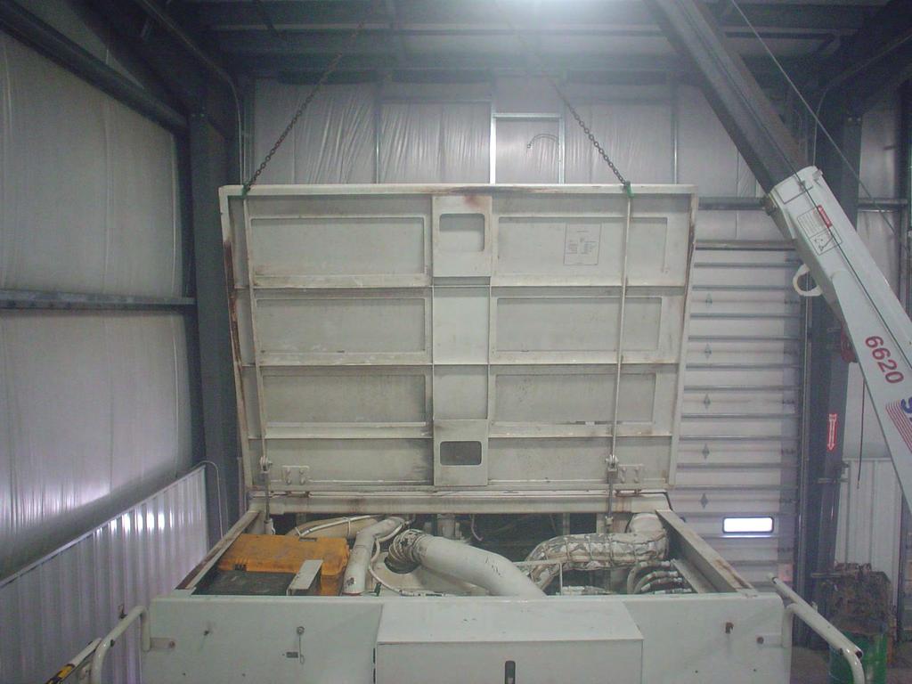
3 REMOVING THE HOOD: SECURE A DOUBLE GRAB HOOK CHAIN TO THE HOOD ON THE OUTSIDE OF THE VERTICAL SLATS. APPLY SLIGHT TENSION TO THE CHAIN.
4


5 REMOVE BOTH HOOD CYLINDER SHOULDER BOLTS ONCE THE HOOD CYLINDER SHOULDER BOLTS ARE REMOVED. USE THE MACHINE S POWER PACK AND LOWER THE HOOD CYLINDERS DOWN TO GET THEM OUT OF THE WAY. USE THE CRANE AND STAND THE HOOD UP VERTICAL. AT THIS POINT, POWER IS NO LONGER NEEDED TO THE MACHINE. LOCK AND TAG OUT THE BATTERY DISCONNECT SWITCHES TO THE MACHINE.
")

6 RIGHT SIDE LEFT SIDE REMOVE THE (QTY 2) 3/8 BOLTS FROM THE HOOD PINS. REMOVE THE PINS

7 LOWER THE HOOD OFF THE MACHINE

8 REMOVE THE LOWER CUTTER HOUSING DOOR AT THE HINGE

9 REMOVE THE SIDE PANEL FROM THE MACHINE

10 INSTALL TWO 3/8 EYE BOLTS INTO THE TWO HOLES ON TOP OF THE SIDE PANEL. ATTACH A CHAIN TO THE EYE BOLTS AND APPLY SLIGHT TENSION.

11

12 REMOVE THE CHARGE AIR PIPE


13 MARK AND REMOVE THE AIR HOSE AND AIR TEMPERATURE CONNECTOR FROM THE AIR PIPE REMOVE THE CLAMPS TO THE AIR PIPE

14 REMOVE THE EXHAUST WRAP FROM THE EXHAUST PIPE

15 REMOVE BAND CLAMPS AT EACH END OF THE EXHAUST PIPE.

16 REMOVE THE EXHAUST PIPE FROM THE SILENCER. THE EXHAUST WILL HAVE TO SLIDE OUT OF THE EXHAUST SILENCER. IN ORDER TO CLEAR THE PIPE FROM THE SILENCER. THE EXHAUST SILENCER WILL NEED TO BE UN- BOLTED SO THE SILENCER CAN SLIDE AWAY FROM THE PIPE.

17 REMOVE THE COVER OVER THE EXHAUST SILENCER


18 BOTTOM VIEW REMOVE BOLTS

19 TOP VIEW REMOVE BOLTS

20 CHOKE A STRAP AROUND THE EXHAUST SILENCER

21 REMOVE THE FOUR BOLTS CONNECTING THE EXHAUST SILENCER ON THE INTERIOR WALL OF THE MACHINE. (LEAVE THE TWO BOLTS TOWARDS THE REAR IN THE MACHINE.
22 SLIDE THE SILENCER TOWARDS THE REAR OF THE MACHINE TO RELEASE THE EXHAUST PIPE.

23 REMOVE THE FILTER BANK: MARK AND REMOVE THE HYD. HOSES FROM THE COORDINATING PUMPS REMOVE THE FILTER BANK FROM THE MACHINE BY REMOVING THE TWO SETS OF ½ BOLTS FROM EACH SIDE OF THE BRACKET

24 THIS IS AN EXAMPLE OF A FILTER BANK REMOVED FROM AN RX-600E

25 MARK AND REMOVE THE 4 EDC CONNECTORS FROM THE PUMPS

26 REMOVE THE HYDRAULIC HOSES PER PUMP

27 PRIMARY CONVEYOR PUMP CASE DRAIN HOSE DOES NOT HAVE TO BE REMOVED FROM THE PUMP. ONCE THE HYDRAULIC TANK IS DRAINED. THE SUCTION LINE CAN BE REMOVED FROM THE TANK.

28 PRIMARY CONVEYOR PUMP CONT. CASE DRAIN HOSE STAYS ATTACHED LOOP FLUSHING HOSE STAYS ATTACHED SUCTION LINE IS DISCONNECTED FROM THE TANK.
29 SECONDARY CONVEYOR PUMP CASE DRAIN HOSE DOES NOT HAVE TO BE REMOVED. THERE IS A BRANCH TEE CONNECTING THE CASE DRAIN FROM THE PRIMARY AND SECONDARY CONVEYOR PUMPS. THESE HOSES DO NOT HAVE TO BE REMOVED FROM THE MACHINE. SUCTION HOSE WILL REMAIN ON THE PUMP AND BE REMOVED FROM THE TANK

30 SECONDARY CONVEYOR CONT. CASE DRAIN HOSES WITH RUN TEE. DO NOT NEED TO BE REMOVED. SUCTION LINE REMAINS ON THE PUMP


31 AUXILIARY PUMP CASE DRAIN IS THE ONLY HOSE THAT CAN REMAIN ON THIS PUMP

32 TRAVEL PUMP CASE DRAIN IS THE ONLY HOSE THAT DOES NOT HAVE TO BE REMOVED FROM THIS PUMP.


33 TRAVEL PUMP CONT. FORWARD PRESSURE HOSE CAN BE REMOVED FROM THE PUMP OR THE TRACTION CONTROL MANIFOLD

34 FAN PUMP MAKE SURE TO MARK REMOVE DIN CONNECTOR FROM THE SOLENOID CASE DRAIN HOSE IS THE ONLY ONE THAT DOES NOT NEED TO BE DISCONNECTED.


35 FAN PUMP CONT. CASE DRAIN 32 JIC CAP


36 CASE DRAIN HOSES TO BE REMOVED MARK AND REMOVE THE CASE DRAIN HOSE MARK AND REMOVE THESE TWO HOSES FROM THE CASE DRAIN MANIFOLD


37 MARK AND REMOVE THE HYD. HOSE ATTACHED TO THE CLUTCH

38 REMOVE THE TWO BOLTS ATTACHING THE PNEUMATIC LINES TO THE MANIFOLD BRACKET. THEN FOLD THE PNEUMATIC LINES BACK OUT OF THE WAY OF THE PUMP DRIVE.

39 REMOVE THE CABLE ATTACHED TO THE HYD OIL TEMPERATURE
 5/8 BOLTS FROM THE SHEAVE.")
40 REMOVE THE SHEAVE FROM THE CLUTCH: USE A CHOKED STRAP TO ATTACH THE SHEAVE TO AN OVERHEAD CRANE. REMOVE THE (QTY 8 ) 5/8 BOLTS FROM THE SHEAVE. LIFT SHEAVE OFF OF THE CLUTCH.

41 AT THIS POINT THE PUMP DRIVE ASSEMBLY IS READY TO BE REMOVED. LOCATE THE TWO LIFTING EYES ATTACHED TO THE TOP OF THE PUMP DRIVE. USE A SMALL CHAIN TO ATTACH THE LIFTING EYES TO AN OVERHEAD CRANE.


42 INSTALL A 20MM EYE BOLT INTO THE CLUTCH FLANGE PLATE. RUN A CLEVIS THROUGH THE EYE BOLT ATTACH A COME-ALONG TO THE CLEVIS AND THE OVERHEAD CRANE. APPLY SLIGHT TENSION TO THE CRANE 20 MM

43 REMOVE THE (QTY 16) BOLTS HOLDING THE PUMP DRIVE TO THE FLYWHEEL OF THE ENGINE


44 ONCE THE BOLTS ARE REMOVED FROM THE BELL HOUSING, REMOVE THE BOLTS FROM PUMP DRIVE MOTOR MOUNTS. THERE WILL BE FOUR BOLTS ON EACH SIDE OF THE PUMP DRIVE. MACHINE REAR SIDE OF THE PUMP DRIVE MACHINE FRONT SIDE OF PUMP DRIVE

45 REMOVE THE TWO ¾ BOLTS FROM THE CLUTCH MOUNT
46 AT THIS POINT, THE PUMP DRIVE IS READY FOR REMOVAL. MAKE SURE THERE IS SLIGHT TENSION ON THE CHAIN AND STRAP ATTACHED TO THE PUMP DRIVE. THE CENTER SECTION SHAFT WILL HAVE TO SLIDE OUT OF THE COUPLING APPROXIMATELY 3 IN. USE PRY BARS OR A POWER PACK TO PUSH THE PUMP DRIVE OUTWARDS. MAKE SURE TO PUSH THE PUMP DRIVE EVENLY OFF THE TORSIONAL COUPLING. (ACCESS POINTS ARE IN THE FOLLOWING SLIDES)
47 REMOVE THE PUMP DRIVE FROM THE MACHINE


48 DRAIN THE OIL OUT OF THE PUMP DRIVE DRAIN PLUG ON BOTTOM FLUID CAPACITY: 19.7 QUARTS
49 LAY THE PUMP DRIVE OVER ON ITS BACK. USING TWO FORK LIFTS OR THE OVERHEAD CRANE. (PLACE 2X4) UNDER THE BELL HOUSING OF THE PUMP DRIVE.

50 REMOVE THE QTY 16 (1/2) CLUTCH BOLTS RAISE THE CLUTCH OFF OF THE PUMP DRIVE.

51 REMOVE THE CLUTCH ADAPTER RING FROM THE PUMP DRIVE. (THE UNIT WILL COME OUT IN ONE PIECE. DO NOT WORRY ABOUT REMOVING THE OUTER BOLTS)

52 WRAP TWO STRAPS THROUGH THE ADAPTER AND LIFT THE ADAPTER PLATE OFF THE PUMP DRIVE.
53 REMOVE THE (QTY 8) M12 X 30 BOLTS FROM THE CENTER SECTION
54 TAKE QTY 2 OF THE EXISTING BOLTS AND USE THEM FOR PUSH OFF BOLTS IN THE TWO HOLES.

55 INSTALL TWO 16MM EYE BOLTS INTO THE FLANGE RING. ATTACH A CRANE TO THE EYE BOLTS AND LIFT THE CENTER SECTION OUT OF THE PUMP DRIVE.

56 REMOVE THE EXISTING OIL SEAL

57 LOCTITE 5699 GREY USE A HIGH PERFORMANCE SILICONE GASKET MAKER AND APPLY TO THE EXTERIOR RING AS SHOWN ABOVE.

58 INSTALL THE NEW CENTER SECTION. (DO NOT INSTALL RADIAL SEAL)


59 INSTALL THE QTY 8 BOLTS FROM THE CENTER SECTION. (USE 242 LOCTITE)

60 RE-INSTALL THE CLUTCH PLATE ADAPTER. USE 271 LOCTITE ON THE QTY 8 BOLTS

61 TORQUE BOLTS TO 250 FT LBS.

62 RE-INSTALL THE CLUTCH TO THE PUMP DRIVE. (USE 242 LOCTITE)

63 STAND THE PUMP DRIVE BACK UP VERTICAL. USING TWO FORK LIFTS OR THE OVERHEAD CRANE.


64 INTERNAL PUMP DRIVE SIDE EXTERNAL PUMP DRIVE SIDE


65 THE SEAL SHOULD BE FLUSH AGAINST THE FACE OF THE PUMP DRIVE

66 REFILL THE PUMP DRIVE WITH 19.7 QUARTS OF (SUMMIT SH1010 POLY-ALPHA OLEFIN BASED SYNTHETIC LUBE)
67 REMOVE TORSIONAL COUPLING FROM THE FLYWHEEL OF THE ENGINE
68 REMOVE THE 5/8 BOLTS AT 3 O CLOCK AND 9 O CLOCK POSITIONS FIRST. INSTALL (QTY 2) 5/8 X 6 BOLTS INTO THESE LOCATIONS. REMOVE THE REMAINING 5/8 BOLTS FROM THE TORSIONAL COUPLING

69 SLIDE THE TORSIONAL COUPLING AWAY FROM THE FLYWHEEL OF THE ENGINE
 5/8 X 6 BOLTS LIFT TORSIONAL COUPLING OUT OF THE")
70 RUN A STRAP THRU THE CENTER OF THE TORSIONAL COUPLING AND ATTACH TO A CRANE WITH SLIGHT TENSION REMOVE THE (QTY 2) 5/8 X 6 BOLTS LIFT TORSIONAL COUPLING OUT OF THE MACHINE

71 INSTALL THE NEW TORSIONAL COUPLING TO THE FLYWHEEL OF THE ENGINE
72 INSTALL THE (QTY 6) 5/8 X 1 ¾ BOLTS USING 242 LOCTITE. TORQUE BOLTS TO 170 FT LBS

73 RE-INSTALL THE PUMP DRIVE ASSEMBLY TO THE ENGINE
74 ONCE THE PUMP DRIVE ASSEMBLY IS RE-INSTALLED IN THE TORSIONAL COUPLING. REPEAT THE STEPS OF THIS PROCEDURE IN REVERSE IN ORDER TO PUT THE MACHINE BACK TOGETHER.
This information covers the proper procedure for replacing the Volvo D16F engine in a VT or VNL chassis.
 Volvo Trucks North America Greensboro, NC USA Engine, Replacement DService Bulletin Trucks Date Group No. Page 10.2007 210 139 1(47) Engine, Replacement Volvo D16F VNL, VT W2005773 This information covers
COUNTER SHAFT NUT LOCKING PLATE 1 $ HOIST DRUM CLUTCH EYE BOLTS 1 $ LEFT DRUM CLUTCH THREADED PIN 2 $ 138.
 1 2184 PULLEY FOR RADIATOR FAN 1 $ 326.25 2 2184 PULLEY FOR RADIATOR FAN 1 $ 326.25 3 3331 REAR DRUM BRAKE RETURN SPRING 5 $ 51.31 5 10285 LEFT REAR DRUM BRAKE AIR CAN REACH ROD ( LONG ROD ) 1 $ 85.12
STX-26 Stump Grinder
 Form No. 3365-311 Rev B STX-26 Stump Grinder Model No. 23210 Serial No. 310000001 and Up Model No. 23210G Serial No. 310000001 and Up Register at www.toro.com. Original Instructions (EN) *3365-311* B Ordering
SWING DOOR SOFT ENCLOSURE (part# 16733)
") 800-643-7332 americanlandmaster.com This kit is for use with all fullsize, 2 passenger ALM utility vehicles. SWING DOOR SOFT ENCLOSURE (part# 16733) NOTE TOOLS REQUIRED Drill 1/4 Drill Bit 7/16 Wrench
800-643-7332 americanlandmaster.com This kit is for use with all fullsize, 2 passenger ALM utility vehicles. SWING DOOR SOFT ENCLOSURE (part# 16733) NOTE TOOLS REQUIRED Drill 1/4 Drill Bit 7/16 Wrench
TRX-26 Trencher. Model No Serial No and Up * * B. Register at Original Instructions (EN)
") Form No. 3414-278 Rev B TRX-26 Trencher Model No. 22974 Serial No. 400000000 and Up Register at www.toro.com. Original Instructions (EN) *3414-278* B Ordering Replacement Parts To order replacement parts,
Form No. 3414-278 Rev B TRX-26 Trencher Model No. 22974 Serial No. 400000000 and Up Register at www.toro.com. Original Instructions (EN) *3414-278* B Ordering Replacement Parts To order replacement parts,
Retriever PARTS LIST Advance MODEL 5200G(OBSOLETE)
") Retriever PARTS LIST Advance MODEL 5200G(OBSOLETE) 5/85 revised 2/01 FORM NO. 56042131 TABLE OF CONTENTS DESCRIPTION PAGE OUTER BODY...1-2 HYDRAULIC PUMP, ENGINE & FUEL TANK...3-4 HYDRAULIC OIL FILTER,
Retriever PARTS LIST Advance MODEL 5200G(OBSOLETE) 5/85 revised 2/01 FORM NO. 56042131 TABLE OF CONTENTS DESCRIPTION PAGE OUTER BODY...1-2 HYDRAULIC PUMP, ENGINE & FUEL TANK...3-4 HYDRAULIC OIL FILTER,
Model 306B H&J Transfer Case Service Manual
 Model 306B H&J Transfer Case Service Manual For innovation using today s technology in demanding situations call: Phone: (877) 327-2116 Fax: (586) 601-1904 e-mail: info@mixerandplantparts.com Mixer & Plant
 Page 1 of 6 Section 03-01C: Engine, 7.5L MFI 1996 Bronco/F-Series Workshop Manual IN-VEHICLE SERVICE Procedure revision date: 06/19/2000 Cylinder Heads Removal SPECIAL SERVICE TOOL(S) REQUIRED Description
Dodge TORQUE-ARM II Speed Reducers Ratios 5, 9, 15, 25, and 40:1
 Installation and Parts Replacement Manual For Dodge TORQUE-ARM II Speed Reducers Ratios 5, 9, 15, 25, and TA0107L TA1107H TA2115H TA3203H TA4207H TA5215H TA6307H TA7315H TA8407H TA9415H TA10507H TA12608H
Model 802 Center Mount Adapter For New Holland 9030 & TV140 Bi-Directional Tractors PARTS CATALOG
 Model 802 Center Mount Adapter For New Holland 9030 & TV140 Bi-Directional Tractors 1 PARTS CATALOG TABLE OF CONTENTS Frame & Tractor Linkage...2,3 Header Linkage & Float Group...4,5 Header Drive Hydraulics
PARTS MANUAL SUPPORTED BY HUSTLER TURF EQUIPMENT AND EXCEL INDUSTRIES, INC.
 SHIBAURA DIESEL ENGINE MODEL: N843 and N843L PARTS MANUAL SUPPORTED BY HUSTLER TURF EQUIPMENT AND EXCEL INDUSTRIES, INC. Table of Contents Chapter 1 General Information....................................
IN-VEHICLE REPAIR. Oil Pan Lower. Removal. 2. Disconnect the LH and RH battery ground cables. For additional information, refer to Section
 303-01C-1 IN-VEHICLE REPAIR Oil Pan Lower Special Tool(s) 3-Bar Engine Support 303-F070 Lifting Eyes 303-D030 303-01C-1 2. Disconnect the LH and RH battery ground cables. For additional information, refer
B190 8 H.P. Lawn Vacuum (1995) Page 1 of 22 Chute Assembly
 Page 1 of 22 Chute Assembly") 245-315B190 8 H.P. Lawn Vacuum (1995) Page 1 of 22 Chute Assembly 245-315B190 8 H.P. Lawn Vacuum (1995) Page 2 of 22 Chute Assembly Ref # Part Number Qty S/P/F Description 1 681-0068 1 S CHUTE ASSEMBLY
245-315B190 8 H.P. Lawn Vacuum (1995) Page 1 of 22 Chute Assembly 245-315B190 8 H.P. Lawn Vacuum (1995) Page 2 of 22 Chute Assembly Ref # Part Number Qty S/P/F Description 1 681-0068 1 S CHUTE ASSEMBLY
UNIT CODE L177 EUROPE SECTION 13 OPTIONS
 06/2005 EUROPE SECTION 13 OPTIONS DESCRIPTION PAGE ACCUMULATOR AND ATTACHING PARTS... 13-13 AUXILIARY TUBE EXTENSIONS TWO AND THREE STAGE FULL FREE-LIFT... 13-30 TWO STAGE LIMITED FREE-LIFT... 13-28 BACK-UP
STX-26 Stump Grinder
 Form No. 3383-656 Rev B STX-26 Stump Grinder Model No. 23208 Serial No. 314000001 and Up Model No. 23208G Serial No. 314000001 and Up Register at www.toro.com. Original Instructions (EN) *3383-656* B Ordering
CS340ES. Property of - Not for Resale A1
 A1 CYLINDER HEAD - CYLINDER 1 8G8-11111-00-00 HEAD, CYLINDER 1......... 1 2 8G8-11121-00-00 HEAD, CYLINDER 2......... 1 3 NGK-BR9ES-00-00 PLUG, SPARK............. 2 4 8G8-11181-01-00 GASKET, CYLINDER HEAD
Retriever 5800G/P/D. revised 2/01 Form Number
 Retriever 5800G/P/D PARTS LIST Advance MODELS 56482005, 56482010, 56482015 This parts list is for machines after serial number 221134 All models covered in this manual are OBSOLETE revised 2/01 Form Number
Autodrive Lawn Tractor
 Illustrated Parts Manual Autodrive Lawn Tractor MTD LLC, P.O. BOX CLEVELAND, OHIO -009 Printed In USA Form No. 9-00 (September, 2009) Steering & Front Axle Assembly 2 9 0 2 9 2 20 9 2 20 2 22 2 2 2 2 2
KONE EcoMod Escalator Repair Instructions
 3.3 Replace drive motor NOTE! When moving the step band during the following procedures, always run the escalator on inspection (use hand held pendant control). 3.3.1 Remove drive motor Complete the following
Parts Manual MZ52 /
 Gasoline containing up to 10% ethanol (E10) is acceptable for use in this machine. The use of any gasoline exceeding 10% ethanol (E10) will void the product warranty. Parts Manual MZ52 / 962401 Please
Instruction Manual Dodge Torque-Arm II Speed Reducers Ratios 5, 9, 15, 25, and 40:1
 Instruction Manual Dodge Torque-Arm II Speed s Ratios 5, 9, 5, 25, and 40: TA007L TA3203H TA6307H TA945H TA07H TA4207H TA735H TA0507H TA25H TA525H TA8407H TA2608H These instructions must be read thoroughly
New Holland Workmaster 25s
 New Holland Workmaster 25s ROPS Cab ** Shown with optional equipment New Holland Workmaster 25s ROPS Cab This ROPS cab is designed and built to fit the New Holland Workmaster 25s tractor. Designed and
REMOVAL & INSTALLATION
 REMOVAL & INSTALLATION NOTE: For reassembly reference, label all electrical connectors, vacuum hoses and fuel lines before removal. Also place mating marks on engine hood and other major assemblies before
9/9/2014 F15MSHC 2004 / TOP COWLING Yamaha Motor Corporation, U.S.A. All rights reserved.
 F5MSHC 00 Page of 6 9/9/0 F5MSHC 00 / TOP COWLING 0 Yamaha Motor Corporation, U.S.A. All rights reserved. F5MSHC 00 Page of 6 9/9/0 Part List F5MSHC 00 / TOP COWLING REF - NO PART NUMBER PART NAME QUANTITY
3 October 2016 PN# V Dodge Twin Turbo Kit (I-00274) ½ D o d g e 2 4 v I S B
 ½ D o d g e 2 4 v I S B") 3 October 2016 PN#1045320 24V Dodge Twin Turbo Kit (I-00274) 1 DOWNLOAD ENHANCED INSTALL MANUALS AT dieselperformance.com BD Twin Turbo Kit 1998½- 2 0 0 2 D o d g e 2 4 v I S B Part# 1045320 PLEASE READ
3 October 2016 PN#1045320 24V Dodge Twin Turbo Kit (I-00274) 1 DOWNLOAD ENHANCED INSTALL MANUALS AT dieselperformance.com BD Twin Turbo Kit 1998½- 2 0 0 2 D o d g e 2 4 v I S B Part# 1045320 PLEASE READ
LIFT N LOAD INSTALLATION, MAINTENANCE, & SAFETY INSTRUCTIONS (800)
") LIFT N LOAD INSTALLATION, MAINTENANCE, & SAFETY INSTRUCTIONS (800) 272-6276 001-321-757-7611 www.cramarotarps.com Plants In: Delaware, Florida, Massachusetts, Nevada, Ohio, and Canada General Information
LIFT N LOAD INSTALLATION, MAINTENANCE, & SAFETY INSTRUCTIONS (800) 272-6276 001-321-757-7611 www.cramarotarps.com Plants In: Delaware, Florida, Massachusetts, Nevada, Ohio, and Canada General Information
SAF-T-LINER MVP-ER PARTS MANUAL. Doors Section. Page 4-1. Doors 10/96
 Doors Section Doors Page 4-1 Stepwell - Outward Opening Page 4-2 Doors Stepwell - Outward Opening Item Part Num. Number Qty. Description Notes 1 47001449 1 Trim - Step, Entrance, Diamond Plate 2 47001450
D8 S/n 1H, 8R, 2U, & 13A
 Caterpillar Service Manual D8 S/n 1H, 8R, 2U, & 13A Service Manual THIS IS A MANUAL PRODUCED BY JENSALES INC. WITHOUT THE AUTHORIZATION OF CATERPILLAR OR IT S SUCCESSORS. CATERPILLAR AND IT S SUCCESSORS
ENGINE - V8. Seal - crankshaft - rear. Refit 1. Ensure both seal location and running surface on crankshaft are clean.
 REPAIRS Seal - crankshaft - rear 1. Ensure both seal location and running surface on crankshaft are clean. 1. Automatic gearbox models: converter drive plate. ENGINE - V8, REPAIRS, Plate - drive - automatic.
Pick-Up Broom (Includes Optional Gutter Brush)
") Optional Gutter Brush Assembly Pick-Up Broom (Includes Optional Gutter Brush) 6 5 6 9 3 5 9 A B A B 0 9 5 Figure. 3 6 Model Number PUB. Serial Number. Serial Number 030 - Current Manufacture Date /30/5
Optional Gutter Brush Assembly Pick-Up Broom (Includes Optional Gutter Brush) 6 5 6 9 3 5 9 A B A B 0 9 5 Figure. 3 6 Model Number PUB. Serial Number. Serial Number 030 - Current Manufacture Date /30/5
Installation Manual v1.0: MST Turbo Kit ( ) 5.9L Dodge. Please read all instructions before installation.
 5.9L Dodge. Please read all instructions before installation.") Installation Manual v1.0: MST Turbo Kit (2003-2007) 5.9L Dodge Please read all instructions before installation. Figure 1: MST Kit Contents Figure 2: MST Hardware Kit Please make sure all of the components
Installation Manual v1.0: MST Turbo Kit (2003-2007) 5.9L Dodge Please read all instructions before installation. Figure 1: MST Kit Contents Figure 2: MST Hardware Kit Please make sure all of the components
74901, Z Master G3 Riding Mower, with 48in TURBO FORCE Side Discharge Mower, 2011 (SN ) : BRAKE HANDLE ASSEMBLY NO.
 : BRAKE HANDLE ASSEMBLY NO.") 74901, Z Master G3 Riding Mower, with 48in TURBO FORCE Side Discharge Mower, 2011 (SN 311000001-311999999) : BRAKE HANDLE ASSEMBLY NO. 1 Page 1 of 52 74901, Z Master G3 Riding Mower, with 48in TURBO FORCE
74901, Z Master G3 Riding Mower, with 48in TURBO FORCE Side Discharge Mower, 2011 (SN 311000001-311999999) : BRAKE HANDLE ASSEMBLY NO. 1 Page 1 of 52 74901, Z Master G3 Riding Mower, with 48in TURBO FORCE
Z-Force 60 KW 53AA5DBJ Page 1 of 57 Air Filter & Muffler
 Z-Force 60 KW 53AA5DBJ Page 1 of 57 Air Filter & Muffler Z-Force 60 KW 53AA5DBJ Page 2 of 57 Air Filter & Muffler Ref # Part Number Qty S/P/F Description 11011 KM-11011-7003 1 S CASE-AIR FILTER 11013 KM-11013-7009
Pick-Up Broom (Includes Optional Gutter Brush)
") Pick-Up Broom (Includes Optional Gutter Brush) Model Number PUB. Serial Number. Serial Number 030-8990 & 9000-060 (899, 8995, 8996 & 8997 are updated design) Manufacture Date /30/5 - /6/7 Phone: 30-393-7080
Pick-Up Broom (Includes Optional Gutter Brush) Model Number PUB. Serial Number. Serial Number 030-8990 & 9000-060 (899, 8995, 8996 & 8997 are updated design) Manufacture Date /30/5 - /6/7 Phone: 30-393-7080
PARTS LIST WRANGLER 26-VS
 PARTS LIST WRANGLER 26-VS ELECTRICAL WIRING ITEM PART NO. DESCRIPTION QTY. 1 2694161 UPPER WIRING HARNESS 1 2 2694171 LOWER WIRING HARNESS 1 3 2490811 BRUSH MOTOR WIRE ASSEMBLY 1 4 2396141 WIRE ASSEMBLY
MODEL SUPER P Parts List
 MODEL Parts List UNIT SERIAL NUMBER MANUAL NUMBER: EFFECTIVE 05/2016 1330 76TH AVE SW CEDAR RAPIDS, IA 52404-7052 PHONE (319) 363-8281 FAX (319) 286-3350 www.highwayequipment.com Copyright 2007 Highway
MAINTENANCE SXV / RXV
 MAINTENANCE SXV / RXV 450-550 3.1.12. HANDLEBAR AND CONTROLS Screw securing clutch control to handlebar M6 10 Throttle control screw M6 4 Ignition switch screw M8 24 FOOTRESTS Footrest support bracket
CAUTION: When aligning timing marks, always rotate engine by turning the crankshaft. Failure to do so will result in valve and/or piston damage.
 REMOVAL Timing Chain 1. Disconnect negative battery cable. 2. Drain cooling system. 3. Remove upper intake manifold. 4. Remove cylinder head covers, crankshaft vibration damper, and timing chain cover.
RUFNEK 80 DESIGN SERIES 001 SERVICE MANUAL INTRODUCTION AND THEORY OF OPERATION...2 ASSEMBLY NUMBER EXPLANATION...2 WINCH MODEL CODES...
 RUFNEK 80 DESIGN SERIES 001 SERVICE MANUAL INTRODUCTION AND THEORY OF OPERATION...2 ASSEMBLY NUMBER EXPLANATION...2 WINCH MODEL CODES...2!WARNING!...3 MAINTENANCE...4 GENERAL DISASSEMBLY...5 A. MOTOR DISASSEMBLY...5
Illustrated Parts & Packing List 528 Gandrud Road, Owatonna, MN For a complete distributor & dealer list go to
 Illustrated Parts & Packing List 528 Gandrud Road, Owatonna, MN 55060 For a complete distributor & dealer list go to www.gandy.net 66GW27F Orbit-Air Applicator 120 Cu. Ft. Hopper w/ 27 (2 ) Openings, Fertilizer
Model No. EK8100 POWER CUTTER
 1 / 7 2 / 7 3 / 7 4 / 7 5 / 7 6 / 7 7 / 7 1 / 5 Item Parts No. Description I/C Qty N/O Opt. 1 Opt. 2 Note 001 168507-3 TANK CAP COMPLETE 1 D10 INC. 2 002 213080-9 O RING 29.5 1 003 163499-1 SUCTION HEAD
S/N 1H019H - 1H310H Page 1 of 33 46" Cutting Deck Assembly
 1180 S/N 1H019H - 1H310H Page 1 of 33 46" Cutting Deck Assembly 1180 S/N 1H019H - 1H310H Page 2 of 33 46" Cutting Deck Assembly 1 17982 1 S Reinforcement Spindle Plate 2 618-0430 1 S Spindle Assembly w/
CARBURETOR. Preliminary Check. Removal of DuraForce Carburetor
 Fuel Leaks From Carburetor (Leaking starts after running, stops after shutdown) Note: This condition which does NOT drain the fuel tank is called spit-back. Possible Causes Engine RPM out of proper range
MZ 52LE. Parts Manual. Zero Turn Mower /
 Parts Manual MZ 52LE Zero Turn Mower / 9677406-00 Please read the operator manual carefully and make sure you understand the instructions before using the machine. When you need spare parts or support
Hydrostatic Zero-Turn Commercial Riding Mower
 Hydrostatic Zero-Turn Commercial Riding Mower Professional Turf Equipment 54" Fabricated Deck ILLUSTRATED PARTS LIST TABLE OF CONTENTS Frame Assembly.................................. 3 54" Fabricated
9/8/ MSHZ 2001 / TOP COWLING Yamaha Motor Corporation, U.S.A. All rights reserved.
 9.9MSHZ 00 Page of 47 9/8/04 9.9MSHZ 00 / TOP COWLING 04 Yamaha Motor Corporation, U.S.A. All rights reserved. 9.9MSHZ 00 Page of 47 9/8/04 Part List 9.9MSHZ 00 / TOP COWLING REF - NO PART NUMBER PART
PARTS MANUAL. Time Saver Wide Cut Mower. I N E CUB G E N U
 PARTS MANUAL Time Saver Wide Cut Mower G E N U FAC TORY I N E PARTS 1-800-965-4CUB www.cubcadet.com FORM NO. 69-03049 PRINTED IN U.S.A. CUB CADET LLC, P.O. BOX 361131 CLEVELAND, OHIO 44136-0019 1/29/200
Parts Manual MZ5225 /
 Gasoline containing up to 10% ethanol (E10) is acceptable for use in this machine. The use of any gasoline exceeding 10% ethanol (E10) will void the product warranty. Parts Manual MZ5225 / 966690502 Please
CYLINDER. Ref. Part No. Number Description Qty Remarks
 A1 CYLINDER 1 J38-11102-00-00 CYLINDER HEAD ASSEMBLY. 1 2 J38-11133-09-00. GUIDE, INTAKE VALVE..... 2 3 99510-12016-00 PIN, DOWEL.............. 2 4 95811-08070-00 BOLT, FLANGE............ 3 5 95811-08045-00
SERVICE INSTRUCTIONS FOR SEAL REPLACEMENT OF POWER GEAR HYDRAULIC LEVELING LEGS
 SERVICE INSTRUCTIONS FOR SEAL REPLACEMENT OF POWER GEAR HYDRAULIC LEVELING LEGS 82-L0352 REV 8 4-27-2011 WARNING! HYDRAULIC COMPONENTS CAN CAUSE SERIOUS INJURY OR DEATH IF PROPER SAFETY PRECAUTIONS ARE
v Porsche 928
 1985-86 32v Porsche 928 Toll-Free Tech Hot Line: 877-FOR-928M 877-367-9286 Please do not copy this manual and give copies to your friends. Our ability to bring you this supercharger kit at this price relies
CALIFORNIA TRIMMER MOWER MAINTENANCE MANUAL
 CALIFORNIA TRIMMER MOWER MAINTENANCE MANUAL 2 Table of Contents Section 1: General Information Page Handle Assembly Instructions 4 Maintenance All Models 6 Oil Change Procedures All Models 9 Height Adjustment
PARTS LIST WRANGLER 2625 DB
 PARTS LIST WRANGLER 2625 DB 1 NOTES 2 BRUSH GEAR MOTOR ITEM PART NO. PART DESCRIPTION QTY. 2393501 COMPLETE MOTOR ASSEMBLY 1 101 3391221 NEGATIVE LEAD 1 102 3391201 1/4-20 X 7 3/4THRU BOLT 2 103 10-24
Retriever 5100G/P. 11/89 revised 10/02 FORM NO
 Retriever 5100G/P PARTS LIST Advance MODELS 56497000, 56497010 This parts list is for machines after serial number 353005 All models covered in this manual are OBSOLETE 11/89 revised 10/02 FORM NO. 56042216
BRAKES BRAKE SWITCH PARK LEVER (LT-) PISTON ORING LARGE PISTON ORING SMALL BRAKE LINE ADAPTER COOLING RESERVOIR BRACKET
 PISTON ORING LARGE PISTON ORING SMALL BRAKE LINE ADAPTER COOLING RESERVOIR BRACKET") DOOSAN COMMON PARTS MODEL: D20/25/30/33S-5 D35C-5 SERIAL: LR / LS / LT ENGINE = CUMMINS (B3.3 TIER III) SERIAL NUMBER INFO PREFIX MODEL ENGINE FUEL/TRANS BRAKE LR D20/25S-5 CUMMINS B3.3 DIESEL OCDB LS
DOOSAN COMMON PARTS MODEL: D20/25/30/33S-5 D35C-5 SERIAL: LR / LS / LT ENGINE = CUMMINS (B3.3 TIER III) SERIAL NUMBER INFO PREFIX MODEL ENGINE FUEL/TRANS BRAKE LR D20/25S-5 CUMMINS B3.3 DIESEL OCDB LS
Pick-Up Broom (Includes Optional Gutter Brush)
") Pick-Up Broom (Includes Optional Gutter Brush) Model Number PUB. Serial Number. Serial Number 0765-039 Manufacture Date 07/0/5 /30/5 Phone: 320-393-7080 2/29/2 Revised 07/0/5 PUB Features of Virnig Mfg.
Pick-Up Broom (Includes Optional Gutter Brush) Model Number PUB. Serial Number. Serial Number 0765-039 Manufacture Date 07/0/5 /30/5 Phone: 320-393-7080 2/29/2 Revised 07/0/5 PUB Features of Virnig Mfg.
WE JUST MADE YOUR DRIVE A LITTLE MORE RELAXING. THE ENHANCED COVERAGE FOR YOUR BMW CPO VEHICLE.
 WE JUST MADE YOUR DRIVE A LITTLE MORE RELAXING. Introducing THE CERTIFIED PRE-OWNED (CPO) WRAP, THE ENHANCED COVERAGE FOR YOUR BMW CPO VEHICLE. When you purchase a Certified Pre-Owned BMW, you look forward
Online version - not for reprint
 4. CLUTCH, CHAIN DRIVE, CHAIN BRAKE, CHAIN TENSIONER 4. Clutch Drum/Chain Sprocket 43RA007 VA 70RA005 VA - Remove the chain sprocket cover. Disengage the chain brake by pulling the hand guard toward the
Parts Description 2 1/2 Ton Multi-Fuel Part Number NSN
 Parts Description 2 1/2 Ton Multi-Fuel Part Number NSN Filter, M49C Fuel Tanker 4330-00-983- CP20452-0 0998 Tube, M49C Fuel Tanker Pickup Element, Air cleaner 2940-00-804-10912373 7898 Cable, Engine Stop
235/245400, , 28N
 Models 235/245400, 287000, 28N thru W, 310/312/313700 These carburetors have a fixed high speed main jet with adjustable idle, Fig 183. The different carburetors are identified as LMT 1 and up. The letters
Rzr Heater System Part #
 Rzr Heater System Part # 2878135 NOTE: This heater unit installs below the center of the dash. If you have a radio mount kit (Polaris Part # 2876897) you may need to cut the top front corner off the mount
MODEL DPC7311 POWER CUTTER 14" Tank and Handle Grips Model DPC7310 DPC7311
 Tank and Handle Grips 12" 14" POWER CUTTER DPC7310 MODEL 9 11 4 2 3 8 12 14 7 10 25 24 19 22 13 5 30 16 20 29 33 15 1 28 6 18 21 31 26 17 23 27 32 34 37 36 35 209 208 07-05 1 Model DPC7310 Hood, Air filter,
Engine Dismantle and Assemble ( )
") Engine Dismantle and Assemble (21 134 8) Special Tools 15-030A Universal flange-holding wrench 21147 21-147 Vibration damper remover 15030A 16-067 Locator for clutch disc 21-167 Wrench for cylinder head
Engine Dismantle and Assemble (21 134 8) Special Tools 15-030A Universal flange-holding wrench 21147 21-147 Vibration damper remover 15030A 16-067 Locator for clutch disc 21-167 Wrench for cylinder head
CYLINDER. Ref. Part No. Number Description Qty Remarks
 A1 CYLINDER 1 J38-11102-00-00 CYLINDER HEAD ASSEMBLY. 1 2 J38-11133-09-00. GUIDE, INTAKE VALVE..... 2 3 99510-12016-00 PIN, DOWEL.............. 2 4 95811-08070-00 BOLT, FLANGE............ 3 5 95811-08045-00
Personal Protection Equipment (PPE) Safety Glasses Protect eyes Welding Mask Protect eyes and face
 Safety Glasses Protect eyes Welding Mask Protect eyes and face") Table of Contents: Title Page... 1 Introduction... 3 Before Construction... 3 Equipment Needed... 3 Drawings... 4 Construction... 5 1. Cut Sheet Drawings... 5 2. Base... 5 3. Combustion Chamber... 12 4.
Table of Contents: Title Page... 1 Introduction... 3 Before Construction... 3 Equipment Needed... 3 Drawings... 4 Construction... 5 1. Cut Sheet Drawings... 5 2. Base... 5 3. Combustion Chamber... 12 4.
S/N 1H019H - 1H310H Page 1 of 48 42" Cutting Deck Assembly
 1170 S/N 1H019H - 1H310H Page 1 of 48 42" Cutting Deck Assembly 1170 S/N 1H019H - 1H310H Page 2 of 48 42" Cutting Deck Assembly 4 683-0254 1 S Deck Adjustment Bracket w/ Weld Nut 9 710-0528 1 /P Hex Cap
Pick-Up Broom (Includes Optional Gutter Brush)
") Pick-Up Broom (Includes Optional Gutter Brush) Model Number PUB. Serial Number. Serial Number 8050-0300 Phone: 30-393-7080 /9/ Revised 5/0/ PUB Features of Virnig Mfg. Inc. Pick-Up Broom include: Pick-Up
Pick-Up Broom (Includes Optional Gutter Brush) Model Number PUB. Serial Number. Serial Number 8050-0300 Phone: 30-393-7080 /9/ Revised 5/0/ PUB Features of Virnig Mfg. Inc. Pick-Up Broom include: Pick-Up
Hydrostatic Zero-Turn Commercial Riding Mower
 Hydrostatic Zero-Turn Commercial Riding Mower Professional Turf Equipment 0" Fabricated Deck ILLUSTRATED PARTS LIST TABLE OF CONTENTS Frame Assembly.................................. 3 0" Fabricated Cutter
rev 1_09/20/2017 PS-35C EA3500SR
 C 1 Tank, Handle 5 7 6 8 17 9 1 2 10 11 12 13 18 19 20 3 21 4 22 23 14 16 2 1 Tank, Handle 1 1 168507-3 TANK CAP COMPLETE 1 1 INC. 2 1 2 213080-9 O RING 29.5 1 1 1 3 163447-0 GASOLINE FILTER 1 1 1 4 195757-7
LAWN TRACTORS ELECTRIC CLUTCH HYDRO DRIVE SERIES "G"
 Parts Manual for LAWN TRACTORS ELECTRIC CLUTCH HYDRO DRIVE SERIES "G" MODEL LT160H42GBV LT160H42GBV2 LT180H48GBV2 WLT160H42GBV WLT180H48GBV2 McDonough, GA, 30253 U.S.A. COPYRIGHT 2006 SNAPPER PRODUCTS,
INSTALLATION & OWNER S MANUAL
 INSTALLATION & OWNER S MANUAL CAB INSTALLATION INSTRUCTIONS JOHN DEERE 4000 SERIES (4500/4600/4700) (4510/4610/4710) (4120/4320/4520/4720) HARD SIDED CAB ENCLOSURE (p/n 1JD4120AS) SOFT SIDED CAB ENCLOSURE
Lubrication system components, removing and installing
 17-1 Lubrication system components, removing and installing Note: If large quantities of metal particles or other deposits (caused, for example, by partial seizure of the crankshaft or conrod bearings)
OPERATOR S MANUAL MAINTENANCE MANUAL PARTS LIST TURFCO CR-7. Broadcast Top Dresser. Product Number Starting Serial Number P00851
 OPERATOR S MANUAL MAINTENANCE MANUAL PARTS LIST TURFCO CR- Broadcast Top Dresser Product Number 0 Starting Serial Number P00 US Patent,,0,,0, and,, Manual Number DANGER - IF INCORRECTLY USED THIS MACHINE
M-ZT 61. Parts Manual. Zero Turn Mower /
 Parts Manual M-ZT 61 Zero Turn Mower / 967177008-01 Please read the operator manual carefully and make sure you understand the instructions before using the machine. When you need spare parts or support
INSTALLATION INSTRUCTIONS LOKAR COLUMN SHIFT LINKAGE
 INSTALLATION INSTRUCTIONS LOKAR COLUMN SHIFT LINKAGE Part No. ACA-1807 (Ford AOD) STOP! PLEASE READ ALL INSTALLATION INSTRUCTIONS BEFORE BEGINNING INSTALLATION. CALL LOKAR FOR ANY QUESTIONS OR UNCERTAINTIES
6.0 Liter Timing Chain, Crankshaft Sprocket, Camshaft Position Actuator, and Solenoid Valve Replacement
 Special Tools EN 46330 Timing Belt Tensioner Retaining Pin J 8433 Two Jaw Puller J 41478 Crankshaft Front Oil Seal Installer J 41558 Crankshaft Sprocket Remover J 41665 Crankshaft Balancer and Sprocket
CABINET LINER AND DOOR PARTS For Models: KUIS18NNTW0, KUIS18NNTT0, KUIS18NNTB0, KUIS18NNTS0 (White) (Biscuit) (Black) (Stainless Steel)
 (Biscuit) (Black) (Stainless Steel)") CABINET LINER AND DOOR PARTS ICE CUBE MAKER 5 09 Litho In U.S.A. (rrm) (psw) 1 Part No. Rev.A CABINET LINER AND DOOR PARTS 1 Literature Parts 2313820 Use & Care Guide 2324311 Service & Wiring Sheet 2 3400886
CABINET LINER AND DOOR PARTS ICE CUBE MAKER 5 09 Litho In U.S.A. (rrm) (psw) 1 Part No. Rev.A CABINET LINER AND DOOR PARTS 1 Literature Parts 2313820 Use & Care Guide 2324311 Service & Wiring Sheet 2 3400886
25 Horsepower Hydrostatic Zero-Turn Commercial Riding Mower
 MMZ 2, 260 2 Horsepower Hydrostatic Zero-Turn Commercial Riding Mower ILLUSTRATED PARTS LIST " Float Cutter Deck - Figure 1 3 1 27 32 17 6 1 11 31 36 3 19 7 23 1 33 38 18 37 22 3 20 2 10 2 12 21 30 39
1983 BMW 320i. 1.8L 4-CYL 1983 Engines - 1.8L 4-Cylinder Engines - 1.8L 4-Cylinder
 ENGINE IDENTIFICATION 1.8L 4-CYL 1983 Engines - 1.8L 4-Cylinder For engine repair procedures not covered in this article, see ENGINE OVERHAUL PROCEDURES - GENERAL INFORMATION article in the GENERAL INFORMATION
This kit may void factory warranty please check with manufacturer.
 Thank you for purchasing a Sinister Manufacturing Company EGR delete kit. Precision manufactured using aircraft quality 304 stainless steel and billet aluminum; this EGR kit is designed to endure years
It don t mean a thing If it ain t got the swing
 SWING CHUTE SAND/SALT SPREADER INSTALLATION AND OPERATING INSTRUCTIONS SWING CHUTE SPREADER MODELS: 7, 8, 9, 9.5 & 10 MANUAL FOR SPREADER SERIAL NUMBERS AFTER # 20000 It don t mean a thing If it ain t
TRAILER MOUNTED PUMP MODEL B50 DRIVE CYLINDER CIRCUIT HYDRAULIC COMPONENTS & SCHEMATIC
 DRIVE CYLINDER CIRCUIT HYDRAULIC COMPONENTS & SCHEMATIC PAGE 01 SINGLE SHIFT SWING TUBE CIRCUIT HYDRAULIC COMPONENTS & SCHEMATIC PAGE 02 DUAL SHIFT SWING TUBE CIRCUIT HYDRAULIC COMPONENTS & SCHEMATIC PAGE
STX-38 EFI Stump Grinder with Intelli-Sweep
 Form No. 3421-244 Rev A STX-38 EFI Stump Grinder with Intelli-Sweep Model No. 23214 Serial No. 402000000 and Up Register at www.toro.com. Original Instructions (EN) *3421-244* A Ordering Replacement Parts
BLACKBIRD INSTALLATION SUPPLEMENT
 BLACKBIRD INSTALLATION SUPPLEMENT FOR 2008-105 FORD 6.4 LITER DIESEL F-SERIES VERSION 3/10 Parts Blackbird Wiring Manual Installation Supplement 6.4 liter Diesel Owner s Manual Includes Warrantee Registration
DCS7901. Documents DCS Fuel tank, tubular grip. 2 Hood, air filter, muffler. 3 Cylinder, crankcase. 4 Ignition electronics, starter
 Documents 1 Fuel tank, tubular grip 2 Hood, air filter, muffler 3 Cylinder, crankcase 4 Ignition electronics, starter 5 Oil pump, clutch 6 Chain brake 7 Carburetor 8 Special parts for version with electric
BLACKBIRD INSTALLATION SUPPLEMENT
 BLACKBIRD INSTALLATION SUPPLEMENT FOR 2003-7 FORD 6.0 LITER DIESEL F-SERIES DUAL ALTERNATOR VERSION 10/07 Blackbird Installation Supplement for Ford 6.0. Liter Dual Alternator Parts included in the 6.0
Parts Manual for PRO GEAR EXPRESS MID-SIZE WALK BEHIND MOWERS SERIES 0 & 1 POWER UNIT MODEL SPE1250KW SPE140KW SPE150KH SPE151KW SPEL150KH
 Parts Manual for PRO GEAR EXPRESS MID-SIZE WALK BEHIND MOWERS SERIES 0 & 1 POWER UNIT MODEL SPE10KW SPE0KW SPE10KH SPE11KW SPEL10KH MOWER UNIT MODEL SPE30 SPE480 SPE31 SPE481 IT IS POLICY OF SNAPPER TO
INSTALLATION INSTRUCTIONS
 INSTALLATION INSTRUCTIONS Commercial Supplemental Instructions (For use with Commercial & Industrial Sectional Doors Installation & Maintenance Manual) Things to Know Before You Begin This is a supplement
OLYMPIC, SUPER OLYMPIC, ALPINE
 ski-doo S MANUAL 966 ALL MODELS OLYMPIC, SUPER OLYMPIC, ALPINE SNO WM OBIL E VALCOURT, QUE., CANADA OLYHPIQUE SUPER-OLYMPIQUE ALPINE 966 SNO WM OBILE VALCOURT, QUE., CANADA OLYMPIQUE SUPER-OLYMPIQUE ALPINE
Section DH-1. Drive Hydraulics - Charge Pressure Circuit. Drive Hydraulics - Charge Pressure Circuit
 Section DH-1 Drive Hydraulics - Charge Pressure Circuit Drive Hydraulics - Charge Pressure Circuit Last Updated - 04/15 Drive Hydraulics - Charge Pressure Circuit Parts T4022 4/15 25.00 700C Parts DH-R0
800 Deere Rd. Prescott, WI CertiSafe Floor Mount
 800 Deere Rd. Prescott, WI 54021 715-262-4488 sales@kascomarine.com www.kascomarine.com CertiSafe Floor Mount Table of Contents Parts Included Page 3 Tank Penetration. Page 5 Base Assembly.. Page 8 Retrieval
Parts Manual 400A. Band Sawing Machine
 Parts Manual 400A Serial No: 595-10101 to Band Sawing Machine MACHINE SPECIFICATIONS MODEL VOLTAGE CYCLE PHASE SERIAL NO. For your information and future reference, insert pertinent data concerning your
John Deere 4115 Boxer
 John Deere 4115 Boxer Parts List & Mounting Instructions Jodale Perry Printed: 2004/07 Standard Parts List Qty Description Photo L&R Rear Mounting Brackets L&R Front Mounting Brackets 2 Front Bracket Spacers
John Deere 4510, 4610, 4710 Boxer
 John Deere 4510, 4610, 4710 Boxer Parts List & Mounting Instructions Jodale Perry Printed: 2004/02 Standard Parts List Qty Description Photo L&R Rear Mounting Brackets (Upper&Lower) L&R Front Mounting
John Deere 4110 Boxer
 John Deere 4110 Boxer Parts List & Mounting Instructions Jodale Perry Printed: 2004/07 Standard Parts List Qty Description Photo L&R Rear Mounting Brackets L&R Front Mounting Brackets 2 Front Bracket Spacers
Caterpillar Engine 01.00
 Caterpillar Engine 01.00 Engine Port Diagrams Engine Port Diagrams Use the following diagrams to identify engine ports: For a Caterpillar CFE engine, see Fig. 1. For a Caterpillar C-7/C-9 and C-11/C-13
Page 1 of HP B&S Vanguard Engine
 1405 Page 1 of 41 14 HP B&S Vanguard Engine 1405 Page 2 of 41 14 HP B&S Vanguard Engine Ref # Part Number Qty S/P/F Description BS-28Q777-0647-E1 1 14 HP B&S Vanguard Engine 1 BS-496412 1 Cylinder Assembly
14A6816H190 GT-2150 (2003) Page 1 of 28 Carburetor
 Page 1 of 28 Carburetor") 14A6816H190 GT-2150 (2003) Page 1 of 28 Carburetor 14A6816H190 GT-2150 (2003) Page 2 of 28 Carburetor TC-640221 1 /P Carburetor (Incl 184 of Engine Parts Lists) 1 TC-640216 1 Throttle Shaft & Lever Assembly
14A6816H190 GT-2150 (2003) Page 1 of 28 Carburetor 14A6816H190 GT-2150 (2003) Page 2 of 28 Carburetor TC-640221 1 /P Carburetor (Incl 184 of Engine Parts Lists) 1 TC-640216 1 Throttle Shaft & Lever Assembly
Model No. EA6100P PETROL CHAIN SAW
 1 / 6 2 / 6 3 / 6 4 / 6 5 / 6 6 / 6 1 / 5 Item Parts No. Description I/C Qty N/O Sales Purch. Note 001 181114202 TANK CAP CPL. 1 D10 INC. 2 002 963229036 PACKING RING 1 003 908006145 FILLISTER HEAD SCREW
Parts Manual Rev. A
 115 97 79-27 Rev. A Parts Manual Z 248F / 967 844801-00 Please read the operator manual carefully and make sure you understand the instructions before using the machine. Gasoline containing a maximum of