Model 306B H&J Transfer Case Service Manual
|
|
|
- Timothy Ramsey
- 5 years ago
- Views:
Transcription


 327-2116 Fax: (586)")


1 Model 306B H&J Transfer Case Service Manual For innovation using today s technology in demanding situations call: Phone: (877) Fax: (586) info@mixerandplantparts.com Mixer & Plant Parts Mfg Tucker St. Rock Hill, SC /2006
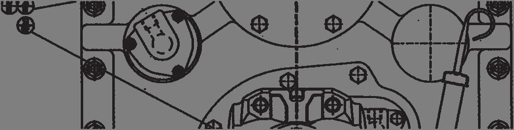
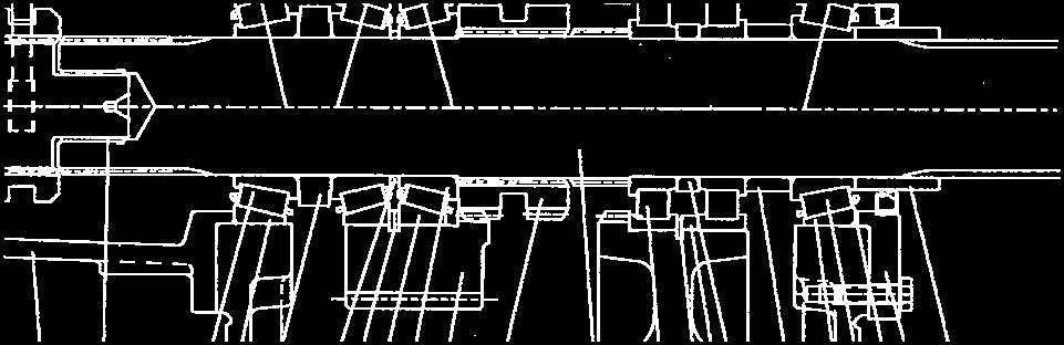
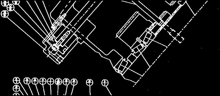
2 Exterior Component Location & Identification page 2


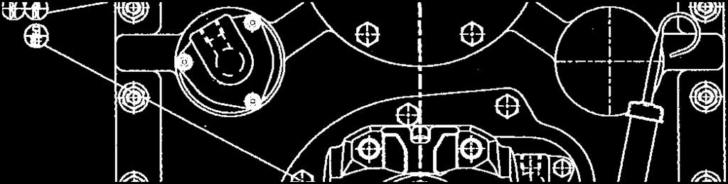
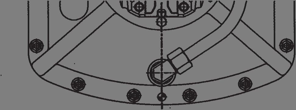

3 Exterior Component Location & Identification page 3


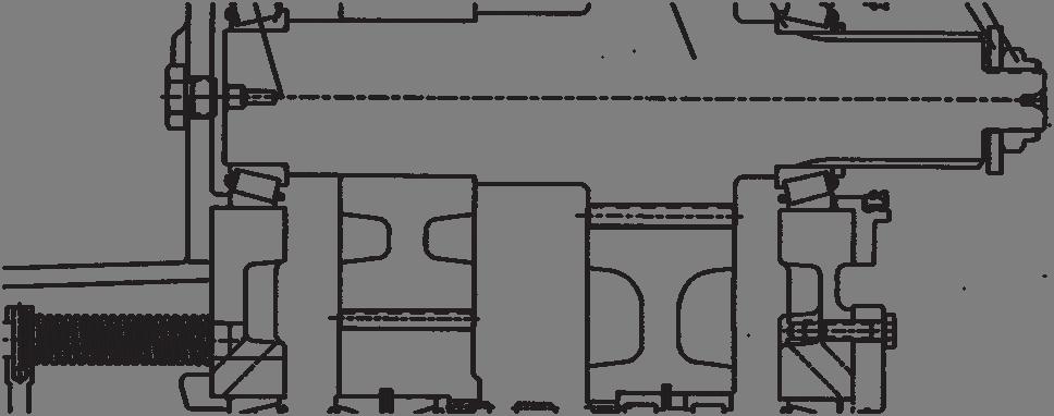
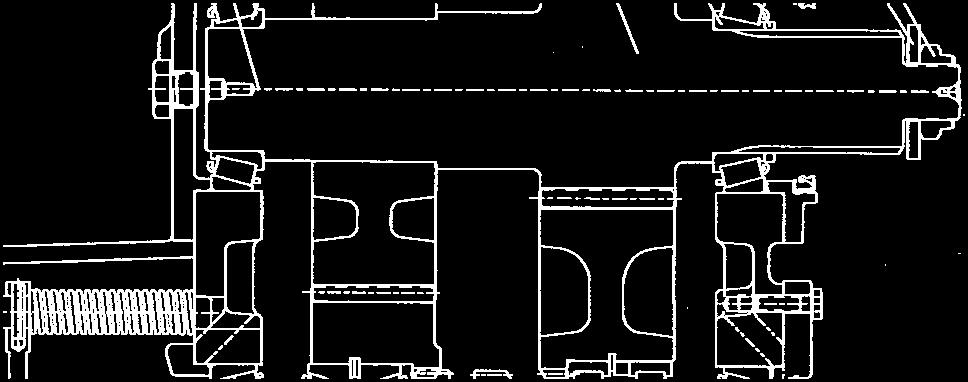
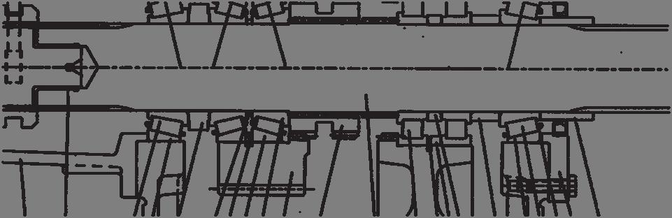
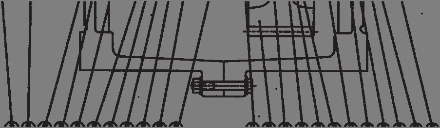
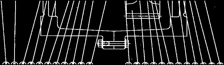
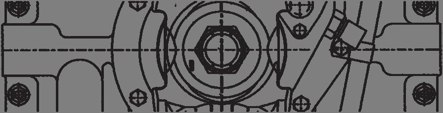
4 Interior Component Location & Identification page 4


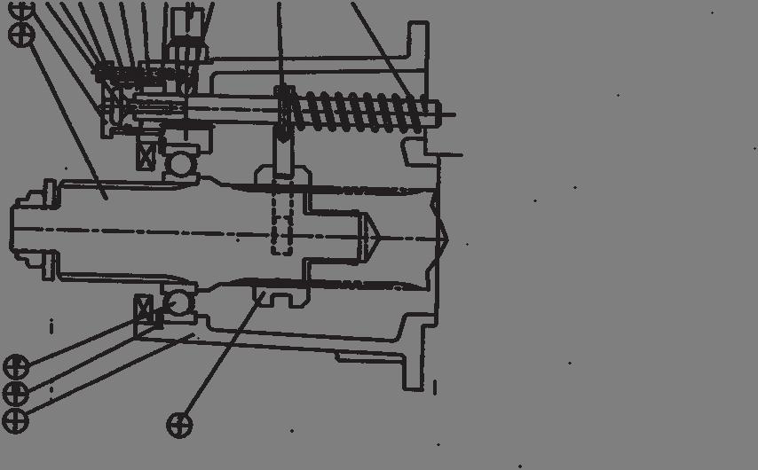
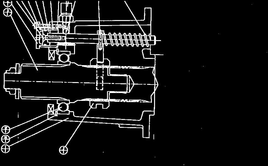
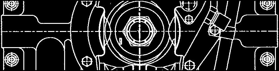
5 Interior Component Location & Identification page 5
6 LUBRICATION LUBRICANT 75W90 Synthetic Lubricant - API MT 1/GL5 LUBRICANT QUANTITY 11.5 quart / 10.9 liter RECOMMENDED CHANGE FREQUENCY Initial Flush & Change... 3,000 mi / 50 hr Scheduled Flush & Change... 50,000 mi / 500 hr Oil Level Check... 2,000 mi / 100 hr Note Since installed angles, front to back and side to side, can vary, it is strongly suggested that the dip stick marking be verified during the initial check to confirm the appropriate lube level during operation. After draining the used lubricant fully, replace the drain plug and clean the dip stick. Fill the unit with 11.5 qt / 10.9 L of the recommended lubricant. Mark the level on the dipstick if it differs from the original mark due to installation angle and cut off the old mark if possible. Do Not mix synthetic and petroleum based lubricants. Early unit failure from foaming and lack of heat transfer will result. Check the level frequently as suggested. You can add many miles to the unit life. page 6
7 Part Number Identification Item Part Number Qty Description Use Front housing half 306H,J Rear housing half 306H,J Rear output bearing retainer 306H,J Rear input bearing retainer 306H,J Front input bearing retainer 306H,J Shift rod housing cap 306H,J Output clutch gear - hi 306H Output clutch gear - hi 306J Output clutch gear - low 306H,J Shift collar 306H,J Output shaft 306HJ Input shaft, pinion & gear 306H Input shaft, pinion & gear 306J Input end fitting bearing spacer 306H,J Front output bearing spacer 306H,J Rear output bearing spacer 306H,J Output clutch gear brg spacer - hi 306H,J Rear output shaft seal sleeve 306H,J A 3 Input shaft bearing shim H,J B 3 Input shaft bearing shim H,J C 3 Input shaft bearing shim H,J A 3 Output shaft bearing shim H,J B 3 Output shaft bearing shim H,J C 3 Output shaft bearing shim H,J Shift rod housing cap gasket 306H,J A 3 Shift piston position shim H,J B 2 Shift piston position shim H,J C 1 Shift piston position shim H,J Shift return spring 306H,J Bearing position snap ring - hi gear 306H,J Speedo sender plug 306H,J High/low shift piston 306H,J High/low shift cylinder 306H,J High/low shift fork and shaft assy 306H,J Yoke/flange retention washer 306H,J Low gear bearing outer spacer 306H,J Low gear bearing inner spacer 306H,J Front output disconnect assembly 306H,J Output gear bearing cup - hi 306H,J Output gear bearing cone - hi 306H,J Output shaft rear bearing cup 306H,J Output shaft rear bearing cone 306H,J 41 JM Input shaft bearing cup 306H,J 42 JM Input shaft bearing cone 306H,J 43 NJ214EC 2 Output gear bearing - low 306H,J 44 20DU20 1 Output shaft disconnect bushing 306H,J 47 N Output gear outer bearing snap ring 306H,J 49 AS324 1 Shift piston o-ring 306H,J 51 1/4-20x Shift cylinder socket head cap screw 306H,J 52 5/16-18x Piston socket head cap screw 306H,J page 7
8 Part Number Identification 53 3/8-16x Brg cap & disconnect cap screw 306H,J 54 3/8-16x Housing flange cap screw 306H,J 55 3/8-16LN 20 Housing flange screw lock nut 306H,J 56 3/8LW 40 Housing flange screw lock washer 306H,J 58 1/2x Housing alignment dowel 306H,J 59 NL8G 1 Shift piston retaining lock washer 306H,J LN 3 Yoke/flange retention lock nut 306H,J 62 12HP50N-S 2 Housing fill plug 306H,J 63 22S-S12M 1 Magnetic housing drain plug 306H,J 65 3/8NPT 1 Breather ell 306H,J 66 MBGF 1 Breather 306H,J A270 1 Speedo sender plug gasket 306H,J Application Specific Parts Input & output end yokes 306H Front output end yoke 306H Front output yoke oil seal 306H Input yoke oil seal 306H Rear output yoke oil seal 306H #12 JIC ell - dip stick tube 306H G 1 Dipstick tube 306H L 1 Dip stick 306H-1 HK Dip stick tube attachment clamp 306H-1 3/8-16x Dip stick tube clamp screw 306H-1 3/8FW 4 Clamp screw washer 306H Disconnect Components Disconnect housing Disconnect shift collar Disconnect output shaft Disconnect shift shaft - see item Disconnect shift fork - see item Disconnect shift cylinder cap Disconnect shift cylinder Disconnect shift piston Disconnect shift return spring Disconnect shift signal switch Disconnect output shaft ball bearing 14 N Disconnect shaft bearing snap ring 21 1/4-20x Disconnect cylinder cap screws 22 5/16-18x Disconnect piston retention screw 23 1/4x Disconnect shift fork roll pin 24 7/16D 1 Shift signal switch actuation ball Shift piston v block seal 26 AS Shift cylinder sealing o-ring 27 NL8G 1 Shift piston screw lock washer A360 1 Shift signal switch washer Disconnect shift fork & shaft assy page 8
9 Assembly / Disassembly Instructions TO DISASSEMBLE THE TRANSFER CASE Drain the oil from the case before removing it from the vehicle. Thoroughly inspect the magnetic drain plug for signs of metal debris. Retain a sample of the oil for further testing if required. Remove the yoke lock nuts (60) and washers (31) from the shaft ends and remove the end fittings (yokes or flanges) from the input and output locations. Remove the three socket head screws (51)from the air inlet shift cylinder cap (28) and remove the cap. Remove the screw (52) and lock washer (59)holding the piston (27) in place. Rotate and support the unit disconnect down blocking it securely. Remove the 12 hex head cap screws (53) securing the bearing retainers (3) & (4) and remove the retainers and the bearing cup shims (20) & (21). Retain the shims for use during the reassembly process. Remove the shift rod cap (6) and washer (22) being careful of the shift spring pressure. Remove the lock nuts, washers and screws (54), (55) & (56) from the housing flanges. Drive out the two dowels (58) in the ends and pry the housings apart. Remove the rear housing (2) and tap out the two bearing cups (39) & (41). Lift the input and output shaft assemblies out of the front housing (1) with shift fork and shaft assembly (37), shift return spring (33) and shift collar (10). Rotate the front housing so that the disconnect assembly (19) can be removed by unscrewing the 6 screws (64). Retain the air shift return spring (9). Tap out the two bearing cups (39) & (41). Lift the input shaft (17) & gear (9) out of the rear housing. Remove the two bearing cones (40), and yoke spacer (20) from the input shaft assembly. The gear cannot be removed. If service of the gear or shaft is required, refer to the parts list for the correct service assembly. Lift out the output shaft (11) & gear (8) & (9) assembly out of the rear housing. Remove both bearing cones (40), spacers (15) & (17) and drive the gear assemblies (9) & (8) off the shaft through the bearing cones. Remove the shift collar (10) and the pocket bushing (44) from the shaft. From the high gear assembly (8) remove the bearing cones (38), spacer (28) and snap rings (25). Remove the two bearings (43) with snap ring (47) and spacers (32) & (33). Flip the remaining housing over flange down and remove the 13 cap screws (64) holding the cover (5) and disconnect assembly (35) in place and remove them. Drive the two remaining bearing cups (39) & (41) from the housing. TO DISASSEMBLE THE DISCONNECT Remove the signal switch (10) and actuation ball (24). Remove three hex head screws (21) from the cylinder cap (6) and remove the cylinder (7). Be careful to retain the sealing o-rings (26). Remove the screw (22) and the piston (8). Remove the collar (2) with fork assembly (29). Tap the shaft (3) through bearing (12) and remove it. Remove the seal, snap ring (14) and bearing (12). page 9
10 CLEANING & INSPECTION All components should be thoroughly cleaned and inspected for signs of fatigue or wear. It is suggested all bearings, bushings, o-rings, piston seals and yoke seals be replaced during any disassembly process particularly if metal chips were found in the oil. Make sure all sealing surfaces are completely cleaned of RTV and hicks/nicks. REASSEMBLY OF THE DISCONNECT ASSEMBLY Install bearing (12), snap ring (14) and the output seal in the housing (1). Insert the disconnect shaft (3) through bearing (12). Install collar (2) with fork assembly (29) onto the shaft. Assemble the o-rings (26) onto the cylinder (7) and assemble it to the housing. Install the piston seal (25) to the piston (8) being careful to position the open end of the V seal out. Install the piston/seal into the cylinder with care and attach the piston to the fork assembly with screw (22). To maximize operational life on early units, refer to the update note found following the disconnect components list. Place the air cap (6) in place and attach it to the housing with 3 screws (21) tightened sequentially to 7ft/lb. Install the shift return spring (9) on the shift shaft and install switch (10) and shift ball (24). TO REASSEMBLE THE TRANSFER CASE With the front housing (1) flange down, install the bearing cups (39) and (41) in their respective bores till they are flush with the housing surface. Install the disconnect assembly (35) with RTV sealant using 7 screws (53). Install cover (5) also with screws (53). Rotate the housing and block it securely disconnect down. Confirm that the bearing cups (39) & (41) in the housing bores are seated securely against the cover and disconnect pilot diameters. Assemble the input shaft (12) with bearing cones (42) on each end seated securely against the shaft shoulders. Drop the shaft into the bearing cup in the front housing half. Place a bearing cone (38) into the high gear (8) bore and press in a bearing cup (37). Drive it just past the snap ring groove. Install snap rings (25) and spacer (18) and press the remaining cup into the gear seating it completely and solidly. Turn the gear over and reseat the first cup. The cups should be seated securely. This is important to proper operation. Insert the remaining bearing cone and clamp the gear through the cones and spin to seat the bearings properly. Bearing adjustment For high gear (8), install both bearing cones (44) along with spacer (18) and about.045 of shims into the gears. Using a press, clamp the bearings through the cones and spin the gear to seat the bearings. Make sure both cups are seated securely against the snap ring. Use shims (25) adjust the end play to.000/.001 when a light pressure is applied to the gear using a pry bar and the gear rotates one half to one rotation when spun. Add an additional.005 to the shim pack to compensate for bearing expansion from heat. For low gear (9), press into the bore the first roller bearing (43) followed by snap ring (47), spacers (32) & (33) and the second bearing (43). Note: the rear output yoke lock nut must be tightened to 300 lb/ft to maximize bearing life. page 10
11 Install one of the gears onto the output shaft (11), install the shift collar (10) and install the other gear assembly making sure both seat properly against the spline section. Install spacers (15) & (17) in their appropriate positions on shaft (11) being careful not to damage the ID of the spacers. Add a bearing cone (40) to each end seating it securely. Place the assembled output shaft with shift fork assembly (29) into the lower bore of housing (1). Place the shift return spring on the shift shaft. Apply sealant to the housing flange sealing surface and install the rear housing (2) aligning it with the shift shaft and two dowels (58). Bolt the two halves together with screws, locknuts and washers (54), (55) & (56). Tap bearing cups (39) & (41) into housing (2) and seat them against the mating cones. Using screws (53), install bearing retainers (3) & (4) tightening the screws while rotating the shafts to properly seat the bearings until all end play is removed. Remove the retainers and measure the depth from the housing face to the bearing cup shoulder. Subtract that measurement from the depth of the retainer shoulder and add.012 for a bearing preload. Add shims in that amount, strike the housing about the bore to free the cup, apply RTV to the retainer flange and install it with the shims. Insert the appropriate oil seals into the retainers now. Install o-ring (49) on piston (27). add a small amount of RTV to the end of the shift shaft, and attach the piston to the shift shaft with a socket head cap screw and washer (52 ) & (59). Prior to attaching the piston (27)with o-ring (49), with the shift shaft fully extended by the shift return spring, measure the distance between the housing surface where the air cylinder mounts and the end of the shift shaft. Deduct that measurement from and add the result in shims (23) placed under the piston (27). Add a small amount of RTV to the end of the shift shaft, and attach the piston to the shift shaft with a socket head cap screw (with Loctite) and washer (52 ) & (59) tightened to 25 lb/ft.. Install the shift cylinder (29) into the housing and attach it with 3 screws (51) tightened to 12 lb/ft. Replace the end fittings and retain them with washers (31) and lock nuts (60) tightened to 300 lb/ft. Install all plugs and refill the housing with 11.5 quarts of the recommended lubricant. page 11

12 page 12
13 page 13
Gear Products Inc N. 161st E. Ave. Tulsa, OK Phone (918) Fax (918)
 Fax (918)") SERVICE MANUAL Disassembly & Assembly Procedures Worm Gear Swing Drive 003 Series Gear Products Inc. 1111 N. 161st E. Ave. Tulsa, OK 74116 Phone (918) 234-3044 Fax (918) 234-3455 Worm Gear Swing Drive
SERVICE MANUAL Disassembly & Assembly Procedures Worm Gear Swing Drive 003 Series Gear Products Inc. 1111 N. 161st E. Ave. Tulsa, OK 74116 Phone (918) 234-3044 Fax (918) 234-3455 Worm Gear Swing Drive
1. General Description
 1. General Description A: SPECIFICATION 1. MANUAL TRANSMISSION AND FRONT DIFFERENTIAL Type Transmission gear ratio Front reduction gear Rear reduction gear Front differential Center differential Final
Parts List PL_TR-TO-10_0714
 Torque Transfer Solutions TR-TO-10 Series 10-Speed Twin Counter Shaft Manual Transmission Parts List PL_TR-TO-10_0714 14700 Helm Ct. Plymouth, MI 48170 U.S.A. (800) 401-9866 www.tremec.com Copyright 2014
Illustrated Parts List
 Spicer Tandem Axles Illustrated Parts List AXIP0085a January 1994 Single Reduction, Dual Range, & Double Reduction Addendum 461, 462, 463, 521, 581 46,000-65,000 lbs Introduction Single Reduction w/wheel
2001 Dodge RAM 3500 PICKUP
 1 of 76 9/14/2012 7:02 PM 2001 Dodge RAM 3500 PICKUP Submodel: Engine Type: L6 Liters: 5.9 Fuel Delivery: FI Fuel: DIESEL Subarticles MANUAL- NV3500 - DISASSEMBLY MANUAL- NV3500 - DISASSEMBLY MANUAL -
Contents How To Use The Illustrated Parts List... 3 CASE... 4 COUNTERSHAFT ASSY... 7 INPUT SHAFT... 8 KITS & ASSEMBLIES... 9 LEVER ASSY...
 FSO-8406A July 2011 Contents How To Use The Illustrated Parts List... 3 CASE... 4 COUNTERSHAFT ASSY... 7 INPUT SHAFT... 8 KITS & ASSEMBLIES... 9 LEVER ASSY... 10 MAINSHAFT ASSY... 12 MISCELLANEOUS... 14
1. General Description
 1. General Description A: SPECIFICATIONS 1. Type Transmission gear ratio Front reduction gear Rear reduction gear 2. TRANSMISSION GEAR OIL Recommended oil Final Transfer 5-forward speeds with synchromesh
IMPORTANT: Dana made
 Spicer Drive Axles Illustrated Parts List AXIP-0057 - Models Designed BEFORE June 10, 2013 October 2013 D170, D170D, R170, R170D - Single Reduction - Tandem Axles D190, D190D, R190, R190D - Single Reduction
Illustrated Parts List
 More time on the road Illustrated s List FRLO-540C-T November 0 Contents How To Use The Illustrated s List... CASE ASSY... 4 COUNTERSHAFT & BRGS(AUX)... COUNTERSHAFT ASSY... 8 ELECTRONIC CONTROL UNIT...
Steering Gearbox Disassembly
 Steering Gearbox Disassembly Steering Rack Disassembly 5. Unbend the lock washer. Before disassembling the gearbox, wash it off with solvent and a brush. Do not dip seals and O-rings in solvent. 1. Remove
Maintenance Manual MM Transfer Cases. MTC-4208X/XL/XP/XLEV, MTC-4210X/XL/XP/XLEV and MTC-4213X Series Revised 09-16
 Maintenance Manual MM-0861 Transfer Cases MTC-4208X/XL/XP/XLEV, MTC-4210X/XL/XP/XLEV and MTC-4213X Series Revised 09-16 Service Notes About This Manual This manual provides maintenance and service procedures
26 Hume Reserve Court, Nth. Geelong, 3215 Phone: (03) Fax: (03) DUAL RANGE HIGH SPEED INSTALLATION MANUAL. for
 Fax: (03) DUAL RANGE HIGH SPEED INSTALLATION MANUAL. for") 26 Hume Reserve Court, Nth. Geelong, 3215 Phone: (03) 5272 2844 Fax: (03) 5272 2633 GEARLESS CENTRE DIFFERENTIAL FULL-TIME 4X4 TRANSFER CASE CONVERSION DUAL RANGE HIGH SPEED INSTALLATION MANUAL for TOYOTA
26 Hume Reserve Court, Nth. Geelong, 3215 Phone: (03) 5272 2844 Fax: (03) 5272 2633 GEARLESS CENTRE DIFFERENTIAL FULL-TIME 4X4 TRANSFER CASE CONVERSION DUAL RANGE HIGH SPEED INSTALLATION MANUAL for TOYOTA
PARTS MANUAL FOR R22N/H REAR AXLE
 PARTS MANUAL FOR REAR AXLE MARMON-HERRINGTON ALL-WHEEL DRIVE 13001 Magisterial Drive Louisville, KY 40223 TABLE OF CONTENTS REPLACEMENT PARTS & WARRANTY CLAIM PROCEDURE......... 3 DIFFERENTIAL CARRIER
1984 Dodge W250 PICKUP
 1984 Dodge W250 PICKUP Submodel: Engine Type: V8 Liters: 5.2 Fuel Delivery: CARB Fuel: GAS Dana 44 MODELS THROUGH 1984 2. Raise and safely support the vehicle, then remove the wheel hub and bearings as
Geareducer model 2700 and 3000
 USER MANUAL Geareducer model 2700 and 3000 INSTALLATION - OPERATION - MAINTENANCE M02-128C ISSUED 04/2013 READ AND UNDERSTAND THIS MANUAL PRIOR TO OPERATING OR SERVICING THIS PRODUCT. maintenance schedule
Illustrated Parts List
 More time on the road Illustrated s List FRLO-440C November 0 Contents How To Use The Illustrated s List... CASE ASSY... 4 COUNTERSHAFT & BRGS(AUX)... COUNTERSHAFT ASSY... 8 ELECTRONIC CONTROL UNIT...
PARTS MANUAL SUPPORTED BY HUSTLER TURF EQUIPMENT AND EXCEL INDUSTRIES, INC.
 SHIBAURA DIESEL ENGINE MODEL: N843 and N843L PARTS MANUAL SUPPORTED BY HUSTLER TURF EQUIPMENT AND EXCEL INDUSTRIES, INC. Table of Contents Chapter 1 General Information....................................
Illustrated Parts List
 More time on the road Illustrated s List FSO-6406A November 2012 Contents How To Use The Illustrated s List... 3 CASE... 4 COUNTERSHAFT ASSY... 8 INPUT SHAFT... 10 KITS & ASSEMBLIES... 11 LEVER ASSY...
Contents How To Use The Illustrated Parts List... 3 CASE ASSY... 4 COUNTERSHAFT & BRGS(AUX)... 6 COUNTERSHAFT ASSY... 7 ELECTRONIC CONTROL UNIT...
... 6 COUNTERSHAFT ASSY... 7 ELECTRONIC CONTROL UNIT...") FRLOF-16410C-T2 July 2011 Contents How To Use The Illustrated Parts List... 3 CASE ASSY... 4 COUNTERSHAFT & BRGS(AUX)... 6 COUNTERSHAFT ASSY... 7 ELECTRONIC CONTROL UNIT... 8 FILTER REGULATOR... 9 INPUT
FRLOF-16410C-T2 July 2011 Contents How To Use The Illustrated Parts List... 3 CASE ASSY... 4 COUNTERSHAFT & BRGS(AUX)... 6 COUNTERSHAFT ASSY... 7 ELECTRONIC CONTROL UNIT... 8 FILTER REGULATOR... 9 INPUT
Y07121 November 2015
 Y072 November 205 Contents How To Use The Illustrated Parts List... 3 FRONT BEARING COVER ASSY.... 4 FRONT CASE ASSY... 5 INPUT SHAFT ASSY... 7 INTEGRATED AIR SYSTEM... 8 INTERMEDIATE CASE ASSY.... 0 LAYSHAFT
SPICER. WEATHERLYINDEX084 T21 O-ES70-5 October 1993 ES70-5 Series Main Transmission
 SPICER WEATHERLYINDEX084 T2 O-ES70-5 October 993 ES70-5 Series Main Transmission ES70-5 Series Main Transmission For parts or service call us Pro Gear & Transmission, Inc. (877) 776-4600 (407) 872-90 parts@eprogear.com
TC20 Chain Driven Power Take-Off Overhaul Instructions
 TC20 Chain Driven Power Take-Off Overhaul Instructions Table of Contents Section Page Introduction 4 Ordering Repair Parts 4 General Information 5 Special Tools 6 Disassembly See Page 2 Reassembly See
Geareducer models 1800 and 2000
 USER MANUAL Geareducer models 1800 and 2000 INSTALLATION - OPERATION - MAINTENANCE M00-1218C ISSUED 08/2015 READ AND UNDERSTAND THIS MANUAL PRIOR TO OPERATING OR SERVICING THIS PRODUCT. operation and
KC Transmission Overhaul
 KC Transmissions Overhaul Instructions Form No. F-1031 Section 4310 Issue Date Rev. Date 02/08/96 12/30/15 Table of Contents Disassembling.............................. 1 Driven Shaft.................................
TC-200 TRANSFER CASE PARTS MANUAL
 AUTOMOTIVE CORPORATION TC-200 TRANSFER CASE PARTS MANUAL Part Number 873-0042-001 Fabco Automotive Corporation, Livermore, CA Ph: (925) 454-9500 Fax: (925) 454-9501 1-(800) 967-8838 www.fabcoautomotive.com
Illustrated Parts List
 More time on the road Illustrated s List FS-6305A November 2012 Contents How To Use The Illustrated s List... 3 CASE... 4 COUNTERSHAFT ASSY... 8 INPUT SHAFT... 10 KITS & ASSEMBLIES... 11 LEVER ASSY...
Illustrated Parts List
 More time on the road Illustrated s List AT-1202 August 2014 Contents How To Use The Illustrated s List... 3 AIR SHIFT ASSY... 4 CASE (AUX)... 6 CASE (FRONT)... 8 COUNTERSHAFT ASSY... 10 INPUT SHAFT &
Illustrated Parts List
 Illustrated Parts List ZY05289 March 202 Contents How To Use The Illustrated Parts List... 3 AIR SYSTEM... 4 CLUTCH ASSEMBLY... 5 CLUTCH SERVO ASSEMBLY... 6 FRONT BEARING COVER ASSY.... 7 FRONT CASE ASSY...
X Dodge / Chrysler /2. Model 44 /216 Disconnect Front Axles for. W1500 and W2500 Ram
 Dodge / Chrysler 1994-1998 1 /2 Model 44 /216 Disconnect Front Axles for W1500 and W2500 Ram 15 Exploded View 16 Parts Listing ITEM NO. PART NUMBER DESCRIPTION 1 (3) Housing Axle Service 2 (1) Drive Pinion
Contents How To Use The Illustrated Parts List... 3 CASE... 4 COUNTERSHAFT ASSY... 6 INPUT SHAFT... 7 KITS & ASSEMBLIES... 8 LEVER ASSY...
 FS-4005A July 2011 Contents How To Use The Illustrated Parts List... 3 CASE... 4 COUNTERSHAFT ASSY... 6 INPUT SHAFT... 7 KITS & ASSEMBLIES... 8 LEVER ASSY... 9 MAINSHAFT ASSY... 11 MISCELLANEOUS... 12
Y08521 September 2014
 Y0852 September 204 Contents How To Use The Illustrated Parts List... 3 FRONT BEARING COVER ASSY.... 4 FRONT CASE ASSY... 5 INPUT SHAFT ASSY... 7 INTERMEDIATE CASE ASSY... 8 LAYSHAFT ASSY.... 0 LRC ASSEMBLY...
Illustrated Parts List
 Illustrated Parts List 3003340 September 2011 Contents How To Use The Illustrated Parts List...3 AIR FILTER REGULATOR...4 AUXILIARY COUNTERSHAFT ASSY....5 AUXILIARY DRIVE GEAR...6 AUXILIARY MAINSHAFT ASSY...7
STERNDRIVE UNIT 3 B GEAR HOUSINGS MR/ALPHA ONE/ALPHA ONE SS
 STERNDRIVE UNIT 3 B 23146 GEAR HOUSINGS MR/ALPHA ONE/ALPHA ONE SS Table of Contents Page Identification........................... 3B-1 Specifications.......................... 3B-1 Torque Specifications................
Illustrated Parts List
 More time on the road Illustrated s List FS-406A November 202 Contents How To Use The Illustrated s List... 3 CASE... 4 COUNTERSHAFT ASSY... 8 INPUT SHAFT... 0 KITS & ASSEMBLIES... LEVER ASSY... 3 MAINSHAFT
SERVICE MANUAL TC 180 TRANSFER CASE SERVICE MANUAL
 TC 180 TRANSFER CASE SERVICE MANUAL Table of Contents MODEL TC-180, Transfer Case........1.0 Introduction.......1.1 Assembly Views.......... 1.2 LUBRICATION...... 2.0 Recommended Lubricants....2.1 Inspection.........
Transmission Overhaul Procedures-Bench Service
 How to Install the Auxiliary Countershaft Assembly Special Instructions To make auxiliary section assembly easier, you can make an auxiliary section fixture out of a 2" x 12" piece of wood. 3' 1' 3" 4.56"
Contents How To Use The Illustrated Parts List... 3 AIR SHIFT ASSY... 4 CASE (AUX)... 5 CASE (FRONT)... 7 COUNTERSHAFT ASSY... 9 INPUT SHAFT & DRIVE
... 5 CASE (FRONT)... 7 COUNTERSHAFT ASSY... 9 INPUT SHAFT & DRIVE") AT-1202 July 2011 Contents How To Use The Illustrated Parts List... 3 AIR SHIFT ASSY... 4 CASE (AUX)... 5 CASE (FRONT)... 7 COUNTERSHAFT ASSY... 9 INPUT SHAFT & DRIVE GEAR... 10 KITS & ASSEMBLIES... 11
AT-1202 July 2011 Contents How To Use The Illustrated Parts List... 3 AIR SHIFT ASSY... 4 CASE (AUX)... 5 CASE (FRONT)... 7 COUNTERSHAFT ASSY... 9 INPUT SHAFT & DRIVE GEAR... 10 KITS & ASSEMBLIES... 11
MANUAL TRANSAXLE SECTIONMT CONTENTS IDX. Shift Control Components...34
 MANUAL TRANSAXLE SECTIONMT GI MA EM LC EC CONTENTS FE PREPARATION...3 Special Service Tools...3 Commercial Service Tools...5 NOISE, VIBRATION AND HARSHNESS (NVH) TROUBLESHOOTING...6 NVH Troubleshooting
IMCO SCX SERIES INFORMATION, OPERATION & MAINTAINANCE
 IMCO SCX SERIES INFORMATION, OPERATION & MAINTAINANCE Warning! Warning! Warning! Danger! Warning! 1. SCX & SCX4 Drives will not fit on a standard gimbal helmet, IMCO HELMET: #05-8025 Black or #05-8027
MANUAL TRANSAXLE Return to Main Table of Contents
 MANUAL TRANSAXLE Return to Main Table of Contents GENERAL... 2 MANUAL TRANSAXLE CONTROL... 12 SHIFT LEVER ASSEMBLY... 14 MANUAL TRANSAXLE... 15 MANUAL TRANSAXLE ASSEMBLY... 17 FIFTH SPEED SYNCHRONIZER
Overhaul Special Tools Required
 1 of 31 Overhaul - Special Tools Required - Cylinder end seal remover attachment, 07NAD-SR3020A - Pilot collar, 07GAF-PH70100 - Valve seal ring sizing tool, 07NAG-SR3090A - Ball joint boot clip guide,
Ilustrated Parts List
 Spicer Drive Axles Ilustrated Parts List Spicer All Wheel 4 x 4 Drive System AXIP-0400 November 1999 Page to Insert The Spicer 4x4 Drive System Axle models and other equipment covered in this publication
Illustrated Parts List
 Illustrated Parts List TA-J7-400026 (ETS-2040) August 202 Contents How To Use The Illustrated Parts List... AUXILIARY COUNTERSHAFT ASSEMBLY... 4 AUXILIARY DRIVE GEAR ASSEMBLY... 5 AUXILIARY MAINSHAFT ASSEMBLY...
CP-1, CP-2, CP-2L & CPD-2 Series Overhaul
 Replacement of Mechanical Seals for CM, CMU, CS and CSU Series Pumps Installation Instructions Form No. F-1031 Section 5013 Issue Date 03/01/85 Rev. Date 02/08/11 CP-1, CP-2, CP-2L & CPD-2 Series Overhaul
HOLINGER SF GEARBOX MANUAL
 HOLINGER SF GEARBOX MANUAL Approved By: Leigh Nash Date: 26/05/2011 Rev: D Date: 11/11 Holinger Engineering Gearbox Manual Page 1 FOREWORD The Holinger SF is a sequential-shift transaxle designed for use
ADVANCE ADAPTERS INC. Fixed Yoke kit (S.Y.E. Kit)
") ADVANCE ADAPTERS INC. Fixed Yoke kit (S.Y.E. Kit) Instruction Sheet P/N: 50-7905 & 50-7906 KIT CONSISTS OF: No. Qty Part No. Description 1. 1 51-7906 TAILHOUSING, DIECAST 2. 1 52-7905 SHAFT, MAIN OUTPUT
ADVANCE ADAPTERS INC. Fixed Yoke kit (S.Y.E. Kit) Instruction Sheet P/N: 50-7905 & 50-7906 KIT CONSISTS OF: No. Qty Part No. Description 1. 1 51-7906 TAILHOUSING, DIECAST 2. 1 52-7905 SHAFT, MAIN OUTPUT
1994 Mitsubishi Eclipse GS
 APPLICATIONS CHRYSLER MOTORS MANUAL TRANS OVERHAUL - MITSUBISHI W5M & W6M SERIES MANUAL TRANSMISSIONS Mitsubishi W5M31, TRANSMISSION APPLICATIONS (CHRYSLER MOTORS) Vehicle Application Transmission Model
Zoom and Print Options
 1 of 63 8/26/2017, 7:04 AM Vehicle» Transmission and Drivetrain» Transfer Case» Service and Repair» Procedures» Isuzu T150» Overhaul (Unit Repair)» 1. Transfer Case Disassemble Transfer Case Disassemble
TRANSFER CASE Mitsubishi Montero APPLICATION DESCRIPTION TESTING 4WD INDICATOR CONTROL UNIT (MONTERO) DETECTION SWITCH
 DETECTION SWITCH") TRANSFER CASE 1993 Mitsubishi Montero 1991-94 TRANSFER CASES Mitsubishi Dodge; Ram-50 Mitsubishi; Pickup, Montero APPLICATION TRANSFER CASE APPLICATIONS TABLE Application (1) Transmission Model Dodge 1991-93
TRANSFER CASE 1993 Mitsubishi Montero 1991-94 TRANSFER CASES Mitsubishi Dodge; Ram-50 Mitsubishi; Pickup, Montero APPLICATION TRANSFER CASE APPLICATIONS TABLE Application (1) Transmission Model Dodge 1991-93
Model QED-D, QED-A, QED-L
 This supplement is for Field Service use only, as complete dis-assembly and re-assembly of the QED reducer by the customer is NOT recommended. This supplement only extends to single reduction QED units.
Illustrated Parts List
 Spicer Drive Axles Illustrated Parts List AXIP-00322 February 2015 Two-Speed-Planetary Double Reduction 19055T/P, 21065T/P, 22065T/P, 23065T/P Model Table of Contents General Information... 3 How To Use
Illustrated Parts List
 More time on the road Illustrated s List FO-8406A-ASX November 202 Contents How To Use The Illustrated s List... 3 CASE... 4 CONTROLLER ECU & HARNESS... 8 COUNTERSHAFT ASSY... 9 GEAR DISPLAY MODULE...
Installation Instructions for the Tera low range Dana 20 (LOW20)
") Installation Instructions for the Tera low range Dana 20 (LOW20) Tera Manufacturing, Inc. 5251 South Commerce Dr. Murray, Utah 84107 Phone/801.288.2585 Fax/801.288.2571 www.teraflex.biz Attention: Verify
Installation Instructions for the Tera low range Dana 20 (LOW20) Tera Manufacturing, Inc. 5251 South Commerce Dr. Murray, Utah 84107 Phone/801.288.2585 Fax/801.288.2571 www.teraflex.biz Attention: Verify
26 Hume Reserve Court, Nth. Geelong, 3215 Phone: (03) Fax: (03) INSTALLATION MANUAL. for
 Fax: (03) INSTALLATION MANUAL. for") 26 Hume Reserve Court, Nth. Geelong, 3215 Phone: (03) 5272 2844 Fax: (03) 5272 2633 GEARLESS CENTRE DIFFERENTIAL FULL-TIME 4X4 TRANSFER CASE CONVERSION DEDICATED LOW RANGE INSTALLATION MANUAL for TOYOTA
26 Hume Reserve Court, Nth. Geelong, 3215 Phone: (03) 5272 2844 Fax: (03) 5272 2633 GEARLESS CENTRE DIFFERENTIAL FULL-TIME 4X4 TRANSFER CASE CONVERSION DEDICATED LOW RANGE INSTALLATION MANUAL for TOYOTA
Parts Replacement Manual For HYDROIL TORQUE-ARM Speed Reducers Taper Bushed For Char-Lynn H, S, T and 2000 Series 6B Spline Motors
 s Replacement Manual For HYDROIL TORQUE-ARM Speed Reducers Taper Bushed For Char-Lynn H, S, T and 000 Series B Spline Motors SIZES: HXT3B, HXTB/HXTB, HXTC These instructions must be read thoroughly before
Illustrated Parts List
 More time on the road Illustrated s List FS-8206A November 2012 Contents How To Use The Illustrated s List... 3 CASE... 4 COUNTERSHAFT ASSY... 7 INPUT SHAFT... 9 KITS & ASSEMBLIES... 10 LEVER ASSY... 11
DISCLAIMER 2011, MIDWEST TRUCK & AUTO PARTS, INC. ALL RIGHTS RESERVED.
 DISCLAIMER PARTS LISTED IN THIS CATALOG ARE NOT NECESSARILY MANUFACTURED BY THE ORIGINAL EQUIPMENT MANUFACTURER AND ANY REFERENCE TO THE TRADEMARKS OR PART NUMBERS OF OTHERS ARE FOR CROSS REFERENCE INFORMATIONAL
Illustrated Parts List
 Illustrated Parts List Y06259 JUNE 203 CONTENTS HOW TO USE THE ILLUSTRATED S LIST 3 FRONT BEARING COVER ASSEBLY 4 FRONT CASE ASSEBLY 5 INPUT SHAFT ASSEBLY 7 INTEREDIATE CASE ASSEBLY 8 LAYSHAFT ASSEBLY
Telephone:(925) Fax:(925) Lawrence Drive, Livermore, CA
 Fax:(925) Lawrence Drive, Livermore, CA") Telephone:(95)5-9500 Fax:(95)5-950 5 Lawrence Drive, Livermore, CA 955 www.fabcoautomotive.com Table of Contents This manual covers single and dual rear output versions of the TC- two-speed transfer case
Telephone:(95)5-9500 Fax:(95)5-950 5 Lawrence Drive, Livermore, CA 955 www.fabcoautomotive.com Table of Contents This manual covers single and dual rear output versions of the TC- two-speed transfer case
SISU DP-330 DRIVE GEAR. Maintenance Manual
 SISU DP-330 DRIVE GEAR Maintenance Manual Sisu Axles, Inc. Autotehtaantie 1 PO Box 189 Fin-13101 Hameenlinna Finland Phone +358 204 55 2999 Fax +358 204 55 2900 DP330DG.PDF (3/2007) TABLE OF CONTENTS
1. Remove the parking brake assembly. 2. Remove the 4 bolts holding the yoke flange and drum. Remove the yoke flange and drive.
 Disassembly NOTE: To replace the brake assembly, brake shoe and lining assemblies, or other operational components the complete parking brake assembly must be removed from the vehicle. 1. Remove the parking
Illustrated Parts List
 More time on the road Illustrated s List FS-106A November 2012 Contents How To Use The Illustrated s List... 3 CASE... 4 COUNTERSHAFT ASSY... 8 INPUT SHAFT... 10 KITS & ASSEMBLIES... 11 LEVER ASSY... 12
PARTS MANUAL FOR MVG 1200 SERIES
 PARTS MANUAL FOR MVG 1200 SERIES MARMON-HERRINGTON ALL-WHEEL DRIVE E-mail: info@marmon-herrington.com TABLE OF CONTENTS REPLACEMENT PARTS & WARRANTY CLAIM PROCEDURE......... 3 HOUSING MVG 1200/R...................................
SISU MP-330 DRIVE GEAR. Maintenance Manual
 SISU MP-330 DRIVE GEAR Maintenance Manual Sisu Axles, Inc. Autotehtaantie 1 PO Box 189 Fin-13101 Hameenlinna Finland Phone +358 204 55 2999 Fax +358 204 55 2900 MP330DG.PDF (4/2007) TABLE OF CONTENTS
HYDROIL TORQUE-ARM Speed Reducers Taper Bushed For Char-Lynn H, S, T and 2000 Series 6B Spline Motors
 Parts Replacement Manual For HYDROIL TORQUE-ARM Speed s Taper Bushed For Char-Lynn H, S, T and 2000 Series 6B Spline Motors SIZES: 25 25 WARNING: Because of the possible danger to persons(s) or property
Illustrated Parts List
 More time on the road Illustrated s List FSB-406B November 202 Contents How To Use The Illustrated s List... 3 CASE... 4 COUNTERSHAFT ASSY... 7 INPUT SHAFT... 9 KITS & ASSEMBLIES... 0 LEVER ASSY... MAINSHAFT
Service Manual. Example Part Number. Motor Supplier. Motor Number. Ratio. Bail Boss. Input. Model. Shaft. Cover
 Service Manual 0 Series Digger models Example Part Number 0 7 f 0 C 7 Model Ratio Shaft Bail Boss Motor Supplier Motor Number Cover Input This service manual is effective: S/N: 0000 to current date: 0
Instruction Manual For DODGE. Airport Baggage Handling Systems Speed Reducers
 Instruction Manual For DODGE Airport Baggage Handling Systems Speed Reducers ABHS TXT109 - TXT115 - TXT125 ABHS TXT209 - TXT215 - TXT225 ABHS TXT309A - TXT315A - TXT325A ABHS TXT409A - TXT415A - TXT425A
MANUAL TRANS OVERHAUL - BORG-WARNER - T56 6-SPEED MANUAL TRANSMISSIONS Borg-Warner T56 (MM6) 6-Speed
 6-Speed") IDENTIFICATION MANUAL TRANS OVERHAUL - BORG-WARNER - T56 6-SPEED 1998 MANUAL TRANSMISSIONS Borg-Warner T56 (MM6) 6-Speed Transmission has 2 identification labels, located on lower left side of case. One
IDENTIFICATION MANUAL TRANS OVERHAUL - BORG-WARNER - T56 6-SPEED 1998 MANUAL TRANSMISSIONS Borg-Warner T56 (MM6) 6-Speed Transmission has 2 identification labels, located on lower left side of case. One
Illustrated Parts List
 More time on the road Illustrated s List FS-4205B November 2012 Contents How To Use The Illustrated s List... CASE... 4 COUNTERSHAFT ASSY... 8 INPUT SHAFT... 9 KITS & ASSEMBLIES... 11 LEVER ASSY... 1 MAINSHAFT
Illustrated Parts List
 More time on the road Illustrated s List FS-5005A November 2012 Contents How To Use The Illustrated s List... CASE... 4 COUNTERSHAFT ASSY... 8 INPUT SHAFT... 10 KITS & ASSEMBLIES... 11 LEVER ASSY... 12
REDUCER LUBRICATION HORIZONAL APPLICATIONS VERTICAL MOUNT REDUCER INSTALLATION CHAR-LYNN H, S, T AND 2000 SERIES 6B SPLINE MOTOR INSTALLATION
 Parts Replacement Manual For HYDROIL TORQUE-ARM Speed Reducers Taper Bushed For Char-Lynn * H, S, T and 000 Series B Spline Motors SIZES: HXT0A, HXTA, HXT0A These instructions must be read thoroughly before
Dana Spicer Tandem Drive Axles
 Dana Spicer Tandem Drive Axles S400-S Service Manual AXSM-1951 September 1997 For the most current information, visit the Roadranger web site at www.roadranger.com TABLE OF CONTENTS Axle Identification...
ASSEMBLY. Transmission Automatic Transmission 5R44E and 5R55E. Special Tool(s)
") 307-01-1 Automatic Transmission 5R44E and 5R55E 307-01-1 ASSEMBLY Transmission Special Tool(s) Holding Fixture, Transmission 307-262 (T93T-77002-AH) Special Tool(s) Installer, Transmission Extension Housing
307-01-1 Automatic Transmission 5R44E and 5R55E 307-01-1 ASSEMBLY Transmission Special Tool(s) Holding Fixture, Transmission 307-262 (T93T-77002-AH) Special Tool(s) Installer, Transmission Extension Housing
SERVICE MANUAL 375 SERIES DIGGER MODELS
 SERVICE MANUAL 75 SERIES DIGGER MODELS Example Part Number 75 F 0 BP Model Ratio Shaft Bail Boss Motor Supplier Motor Number Back Spin Protection THIS SERVICE MANUAL IS EFFECTIVE: S/N: 00 TO CURRENT DATE:
Contents How To Use The Illustrated Parts List... 3 CASE... 4 COUNTERSHAFT ASSY... 6 INPUT SHAFT... 8 KITS & ASSEMBLIES... 9 LEVER ASSY...
 FS-5406N July 2011 Contents How To Use The Illustrated Parts List... 3 CASE... 4 COUNTERSHAFT ASSY... 6 INPUT SHAFT... 8 KITS & ASSEMBLIES... 9 LEVER ASSY... 10 MAINSHAFT ASSY... 12 REVERSE IDLER GEAR
T-276 Two-Speed Carrier Mounted Input Transmission Transmission montée en entrée de nez de pont à deux vitesses
 TM T-276 Two-Speed Carrier Mounted Input Transmission Transmission montée en entrée de nez de pont à deux vitesses Maintenance Manual MM5.2 Manuel de maintenance MM5.2 Issued 10-03 Edité Octobre 03 Models
Illustrated Parts List
 Illustrated Parts List Y06549 JUNE 203 CONTENTS HOW TO USE THE ILLUSTRATED S LIST 3 CLUTCH HOUSING ASSY 4 FRONT BEARING COVER ASSY 5 FRONT CASE ASSY 6 INPUT SHAFT ASSEBLY 8 INTEREDIATE CASE ASSY 9 LAYSHAFT
Maintenance Instructions
 General Note These instructions contain information common to more than one model of Bevel Gear Drive. To simplify reading, similar models have been grouped as follows: GROUP 1 Models 11, 0, 1,, (illustrated),,
Magnesium Option, Late Model Front Seal, Viton, P/N 67256V Rear Seal, Viton, P/N 67257V Shifter Installed Heat Treated Yoke, P/N
 DESCRIPTION OPTION Magnesium Option, Late Model 80100L Front Seal, Viton, P/N 67256V 80109 Rear Seal, Viton, P/N 67257V 80110L Shifter Installed 80112L Heat Treated Yoke, P/N 62946-6 80119-6 Heat Treated
DISASSEMBLY AND ASSEMBLY
 307-01-1 Automatic Transaxle/Transmission 307-01-1 DISASSEMBLY AND ASSEMBLY Transaxle Special Tool(s) Dial Indicator Gauge With Holding Fixture 100-002 (TOOL-4201-C) Special Tool(s) Test Plate Screw Set,
Single-Reduction Forward Differential Carriers on Tandem and Tridem Axles
 Maintenance Manual 5L Single-Reduction Forward Differential Carriers on Tandem and Tridem Axles Revised 08-15 Service Notes About This Manual This manual provides maintenance and service information for
LoMax 205 CASE & 3:1 GEAR SET. Manufactured by JB CONVERSIONS, INC. Phone: Installation Instructions for the GM NP205 Transfer Case
 LoMax 205 CASE & 3:1 GEAR SET Part No. 2800 Instruction Rev: 2007.08.16 Manufactured by JB CONVERSIONS, INC. Phone: Installation Instructions for the GM NP205 Transfer Case Kit Components: 1. (1) 42x25
Illustrated Parts List
 More time on the road Illustrated s List FS-6406N November 202 Contents How To Use The Illustrated s List... 3 CASE... 4 COUNTERSHAFT ASSY... 7 INPUT SHAFT... 9 KITS & ASSEMBLIES... 0 LEVER ASSY... MAINSHAFT
NP231 SHORT SHAFT "FIXED YOKE" KIT
 Page 1 of 11 KIT CONSISTS OF: No. Qty Part No. Description 1. 1 51-7905 TAILHOUSING, DIECAST 2. 1 52-7905 SHAFT, MAIN OUTPUT 3. 1 300474 SEAL WASHER, REAR YOKE 4 1 300475 YOKE, C.V. REAR 5. 1 300476 NUT,
SECTION Front Drive Axle/Differential
 205-03-i Front Drive Axle/Differential 205-03-i SECTION 205-03 Front Drive Axle/Differential CONTENTS PAGE Axle... 205-03-2 205-03-2 Front Drive Axle/Differential 205-03-2 Axle Special Tool(s) C-Frame
TRANSFER SECTIONTF CONTENTS IDX EXIT. Counter Gear...20
 TRANSFER SECTIONTF GI MA EM LC EC CONTENTS FE CL PREPARATION...2 Special Service Tools...2 Commercial Service Tools...3 NOISE, VIBRATION AND HARSHNESS (NVH) TROUBLESHOOTING...5 NVH Troubleshooting Chart...5
Service Manual. #19 Gearmatic Winch
 Allis Chalmers Service Manual #19 Gearmatic Winch Service Manual THIS IS A MANUAL PRODUCED BY JENSALES INC. WITHOUT THE AUTHORIZATION OF ALLIS CHALMERS OR IT S SUCCESSORS. ALLIS CHALMERS AND IT S SUCCESSORS
REFERENCE ONLY. T12000 Series
 MODEL NO. 11_O_4_F_T_1_2_36_6_-_1_0_0 PART NO. 4261513 ------------------------------------------------ DATE 7-6-99 --------------------------------------------------- Series GRP-T12 " ",. CONVERTER HOUSING,::1,
Installation and Parts Replacement Manual For No. 188D BIO-DISC Reducer
 Installation and Parts Replacement Manual For No. 88D BIO-DISC Reducer These instructions must be read thoroughly before installation or operation. This instruction manual was accurate at the time of printing.
HIGH PERFORMANCE TRANSMISSION PARTS Instructions. Line Pressure Booster Kit. TCC Control Plunger Valve Kit. Line Pressure Modulator Plunger Valve Kit
 Performance Pack Ford 4R100 Part No. HP-4R100-01 Line Pressure Booster Kit Line-to-Lube Pressure Regulator Valve Line Pressure Booster Kit Valve Sleeve O-Rings (2) TCC Control Plunger Valve Kit Front Lube/Drainback
SPECIAL TOOLS Dodge Pickup 5.9L Eng R3500. Fig 1: Identifying Remover C-3985-B (Special Tool) 9/6/13 Printer Friendly View
 9/6/13 Printer Friendly View") Procedures 2003 Dodge Pickup 5.9L Eng R3500 manual transmission SPECIAL TOOLS Fig 1: Identifying Remover C-3985-B (Special Tool) www2.prodemand.com/print/index?content=tabs&module=true&tab=true&terms=true&ymms=false&classname=
Procedures 2003 Dodge Pickup 5.9L Eng R3500 manual transmission SPECIAL TOOLS Fig 1: Identifying Remover C-3985-B (Special Tool) www2.prodemand.com/print/index?content=tabs&module=true&tab=true&terms=true&ymms=false&classname=
ASSEMBLY. Transmission Automatic Transaxle/Transmission. Special Tool(s) Alignment Set, Fluid Pump 307-S039 (T74P X) Special Tool(s)
 Alignment Set, Fluid Pump 307-S039 (T74P X) Special Tool(s)") 307-01-1 Automatic Transaxle/Transmission 307-01-1 ASSEMBLY Transmission Special Tool(s) Adjustment Set, Transmission Band 307-S022 (T71P-77370-A) Special Tool(s) Alignment Set, Fluid Pump 307-S039 (T74P-77103-X)
307-01-1 Automatic Transaxle/Transmission 307-01-1 ASSEMBLY Transmission Special Tool(s) Adjustment Set, Transmission Band 307-S022 (T71P-77370-A) Special Tool(s) Alignment Set, Fluid Pump 307-S039 (T74P-77103-X)
Illustrated Parts List
 More time on the road Illustrated s List FS-4205A November 2012 Contents How To Use The Illustrated s List... CASE... 4 COUNTERSHAFT ASSY... 8 INPUT SHAFT... 9 KITS & ASSEMBLIES... 11 LEVER ASSY... 1 MAINSHAFT
REAR AXLE PARTS.BOOK SS-842 DATE: SPICER PS-7036 AXLE USED WITH PS-1350 AXLE STEERING CYLINDER & steering CYLINDER
 :. :. :. - I _ REAR AXLE PARTS.BOOK SS-8 o DATE: 7--9 SPICER PS-703 AXLE USED WITH PS-350 AXLE 7-9-30 STEERING CYLINDER & 7-9-3 steering CYLINDER o BARAGA PRODUCTS, INC. 55 N. Superior AYe. Baraga. Ul
a. remove counterbalance valves, travel motors and travel drives
 * For further information, contact Caterpillar Service Technology Group. Start By: a. remove counterbalance valves, travel motors and travel drives 1. Remove the counterbalance valve. See, "Disassemble
Set Up. We recommend that you read through this entire set of instructions prior to removing your 231 Transfer case from the Jeep
 Slip Yoke Eliminator Kit for New Process 231 Transfer Case Assemblies Crown Part # SYE231 Kit Components: 1. Rear Housing Assembly (Includes rear housing, rear output seal, rear output bearing and rear
HIGH PERFORMANCE TRANSMISSION PARTS Instructions. Line Pressure Booster Kit. TCC Control Plunger Valve Kit. Line Pressure Modulator Plunger Valve Kit
 Performance Pack Ford 4R100 Part No. HP-4R100-01 Line Pressure Booster Kit Line-to-Lube Pressure Regulator Valve Line Pressure Booster Kit Valve Sleeve O-Rings (2) TCC Control Plunger Valve Kit Front Lube/Drainback
Telephone:(925) Fax:(925) Livermore, California 94551
 Fax:(925) Livermore, California 94551") Telephone:(925)454-9500 Fax:(925)454-9501 Livermore, California 94551 VIII. PARTS MANUAL TC-35 PARTS MANUAL INDEX SECTION THROUGH ASSEMBLED SHAFTS PM2 EXPLODED VIEWS WITH PARTS LISTS Front Output Shaft
Telephone:(925)454-9500 Fax:(925)454-9501 Livermore, California 94551 VIII. PARTS MANUAL TC-35 PARTS MANUAL INDEX SECTION THROUGH ASSEMBLED SHAFTS PM2 EXPLODED VIEWS WITH PARTS LISTS Front Output Shaft
TC 142 & TC 1421 TRANSFER CASE
 AUTO MO TIVE CORPORATION TC 4 & TC 4 TRANSFER CASE PARTS MAN UAL FABCO AUTOMOTIVE CORPORATION, Livermore, CA Ph: (95) 454-9500 Fax: (95) 454-950 -(800) 967-888 www.fabcoautomotive.com 8.0 ILLUSTRATED PARTS